3613-V5 - doallsaws.com · Controls for the optional DBW-15 Buttwelder are described in a seperate...
32
3613-V5 Serial No: 569-04101 to Band Sawing Machine Instruction Manual
Transcript of 3613-V5 - doallsaws.com · Controls for the optional DBW-15 Buttwelder are described in a seperate...

3613-V5
Serial No: 569-04101 to
Band Sawing Machine
Inst
ruct
ion
Man
ual

DAMAGE CLAIM PROCEDURESVISIBLE DAMAGE AT THE TIME OF DELIVERY:
1. Notedamageoncarrier’sdeliveryreceipt.Accepttheshipment.Itcanbereturnedlaterifrepairsare not possible in the field.
2. Requesta“damageinspection”fromthedeliverycarrier:
a. Thecarrierwillsendhisownpeopleorcontractanindependentagencytomakethe inspection.
b. Theinspectorwillrequestasignatureonthereportandleaveacopy.
c. The carrier “damage inspection” report is not final. If additional damage is found when repairsarestarted,contactthecarrierforanotherinspection;oratleastgivethemthe detailsofthedamage.
3. Donotmovetheequipmentfromthereceivingareaandkeepallshippingmaterialsuntilcarrier“damageinspection”reportiscomplete.
4. If possible, take photographs of the damage and keep them for your files. Photos could possibly proveaclaimatalatertime.
5. Keeparecordofallexpensesandbesuretheyaredocumented.
6. Repair damage in the field whenever possible. Carriers encourage this to keep expenses down.
7. You have nine (9) months to file a claim.
1. Youhavefourteen(14)daystoreportdamagenotnotedattimeofdelivery.
a. Reportdamageassoonaspossible.Thismakesiteasiertoprovethatitdidnothappen atcosignee’splant.
b. Inspectmachine(s)carefullybeforemovingfromthereceivingarea.Again,ifmachineis notmoved,itiseasiertoproveyourcase.
2. Requesta“damageinspection”fromthedeliverycarrier:
a. Thecarrierwillsendhisownpeopleorcontractanindependentagencytomakethe inspection.
b. Theinspectorwillrequestasignatureonthereportandleaveacopy.
c. The carrier “damage inspection” report is not final. If additional damage is found when repairsarestarted,contactthecarrierforanotherinspection;oratleastgivethemthe detailsofthedamage.
3. Donotmovetheequipmentfromthereceivingareaandkeepallshippingmaterialsuntilcarrier“damageinspection”reportiscomplete.
4. If possible, take photographs of the damage and keep them for your files. Photos could possibly proveaclaimatalatertime.
5. Keeparecordofallexpensesandbesuretheyaredocumented.
6. Repair damage in the field whenever possible. Carriers encourage this to keep expenses down.
7. You have nine (9) months to file a claim.
CONCEALED DAMAGE:

�
MODEL FIRST SERIAL NO. LAST SERIAL NO.3613-V5 569-04101
PRINTED IN U.S.A. PB-517.3 (10-08)
OPERATOR'S INSTRUCTION MANUALMETAL CUTTING BAND SAW
The follow�ng reg�stered trademarks of the DoALL Company are used �n th�s manual:DoALL and Imper�al B�-Metal.
Foryour informationand futurereference,pertinentdataconcerningyourmachineshouldbewritteninthespacesprovidedabove.Thisinformationisstampedonaplateattachedtoyourmachine.Besuretoprovidemachinemodelandserialnumberswithanycorrespondenceorpartsorders.
Specifications contained herein were in effect at the time this manual was approved for printing. The DoALL Company, whose policy is one of continuous improvement, reserves the right, however, to change specifications or design atanytimewithoutnoticeandwithoutincurringobligations.
DoALL SAWING PRODUCTS2375BTOUHYAVENUEELKGROVE,ILLINOIS60007U.S.A.
PLEASE READ THIS MANUAL CAREFULLY BEFORE OPERATING THE MACHINE!For Sales, Parts and Serv�ce, call1-888-362-5572

��
TABLE OF CONTENTS
Howtoreadyourserialnumber:
MACHINE DIMENSIONS
Floor Plan ............................................................... 1FrontView.............................................................. 2
MACHINE FEATURES
FrontView.............................................................. 3RearView............................................................... 4
INSTALLATION
Location.................................................................. 5OSHANotice!!........................................................ 5Unpacking............................................................... 5Cleaning ................................................................. 5Lifting...................................................................... 5MachineAlignment................................................. 5-6ElectricalInstallation............................................... 6Preparation for Use ................................................ 6
OPERATION
Safety Precautions ................................................. 7UsingtheJobSelector........................................... 7Electrical Controls ................................................... 8Band Speed Controls ............................................. 8Saw Band Preparation ............................................ 8-10Post Adjustment ...................................................... 10Worktable and Tilt Adjustment ................................10-11Wheel Brush and Chip Removal ............................ 11Typical Operation Procedures ................................11-12
LUBRICATION
Lubrication Chart .................................................... 14LubricationDiagram............................................... 15
MAINTENANCE
Replacing Crowned Bandwheel Tires ..................... 16Insert-TypeSawGuides......................................... 16ElectricMotors........................................................ 16Head Components .................................................. 16SpindleDriveBearings........................................... 16WheelBrush........................................................... 16Transmission.......................................................... 16Variable Pulley ........................................................ 16BandDriveBelt....................................................... 16Mist Coolant ............................................................ 16Machine Cleaning ...................................................16-17
TROUBLE SHOOTING..................................18-19
ACCESSORIES
Disc Cutter .............................................................. 20Miter No. 2 Cut-Off (Side Mount) ............................ 20RipFence............................................................... 20HeavyWorkSlides.................................................20-21WorkholdingJaws.................................................. 21Air-Operated Power Feed ....................................... 21Chip Blower ............................................................ 22Mist Coolant ............................................................ 22BandMistLubricator............................................... 22Worklight................................................................. 22Magnifier ................................................................. 22Post Elevating Handwheel ...................................... 22WorktableOptions..................................................22-23Air-Powered Worktable ........................................... 23Universal Calibrated Work Fixture ..........................23-24Protractor Workstop and Alignment Gage .............. 24DBW-15Buttwelder................................................ 24OptionalSawGuides..............................................24-2690°SawGuideBrackets........................................ 26Adjustable Angle Saw Guides ................................ 26DustSpout.............................................................. 26ExtraWorkHeight.................................................. 26BandFiling.............................................................. 27Band Polishing ........................................................ 28LaserLineGeneratorOption.................................. 28

1
MACHINE DIMENSIONSINCHES (± .03)
MILLIMETERS (± 1 mm)
FLOOR PLAN

2
MACHINE DIMENSIONS (Continued....)
INCHES (± .03) MILLIMETERS (± 1 mm)
FRONT VIEW
13"(330.2mm) 79.88"(2029.0mm) 19"(482.6mm) 85.88"(2181.4mm) 25"(635.0mm) 91.88"(2333.8mm) 31"(787.4mm) 97.88"(2486.2mm)
A BD�mens�ons
Work He�ght
3
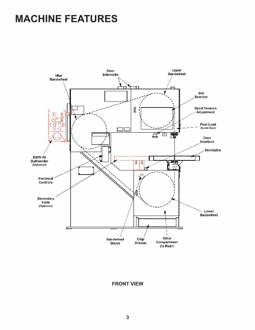
MACHINE FEATURES
FRONT VIEW

4
MACHINE FEATURES (Continued....)
REAR VIEW

5
INSTALLATION All the “left”, “r�ght”, “front” and “rear”
des�gnat�ons �n th�s manual are as v�ewed by the operator fac�ng the mach�ne's electr�cal controls.
LOCATION
1. The floor area required by the standard machine is approximately73.88inches(1876.6mm)inwidthby42.88inches(1089.2mm)inlength.Machineheightforthestandardmachineis79.88inches(2029.0mm). Refer to pages1&2 for furthermachinedimensions.
2. Locate the machine to provide adequate spacefor your sawingneeds. Besurealso toprovidesufficient clearance for loading and unloading of stock,postelevation,dooropening,maintenanceandlubricationprocedures,plusoperationofanymachineaccessories.
OSHA NOTICE!!
OSHA Regulat�on 1910.212 (5B). Machinesdesignedforafixedlocationshall
be securely anchored to prevent walk�ng or mov�ng.
UNPACKING
1. Themachineisfastenedtoandshippedonawoodenskid.Overseasshipmentsarealsocrated.
2. Carefully remove all protective covers, strapping, hold-downbrackets,crating,etc.Then:(a) Removeallboltswhichfastenthemachinetotheshippingskid;(b) Check inside the rear drive compartment forotherremovablebrackets,extramachinepartsorsupplieswhichmighthavebeenplacedthereforshipment;(c) Inspectthemachineandallpartsforshipping damage. Claim procedures are listed on thismanual’sinsidefrontcover.
CLEANING
1. Ifnecessary,usesolventtoremoverust-preventivecoating applied to exposed bare metal surfacesbeforeshipment.
LIFTING
1. Atappedhole is locatedontopof themachine'ssaw head. Screw a forged 3/4-10NC eye-bolt into thisholeforliftingpurposes.Grossweightofthemachine is approximately 1850 pounds (839.2kg).
DO NOT l�ft the mach�ne by �ts saw�ng head.
MACHINE ALIGNMENT
1. Place shims between the floor and the base mounting padsuntilthemachineweightisrestingevenlyonallthebasepads.
Typical Shim Locations.
2. Place a good quality, 10 inch (254.0 mm) master squareontheworktableagainstthepost'sbackside.Measureclearancebetweenthepostandsquarenear the bottom of the post. Clearance should be within0.007-inch±0.005-inch(0.18mm±0.13mm)atthebottomofthepostforstandardmachines.
Squaring Worktable to Post.

6
MACHINE ALIGNMENT (Continued....)
3. Square the worktable to the side of the post bylooseningthetiltlockboltlocatedinthemachine'sframeundertheworktableandmakethenecessaryadjustments. If necessary: (a) Position the worktable'stiltanglepointeratzero(0)onthetiltscale;(b)Tightenthetiltlockbolt.
4. Addorremoveshimsunderthebasepadsuntilthecorrectposttosquareclearanceisobtained.
Themachinemustbeboltedtothefloorforworktable loads over 100 pounds (45.4 kg).
ELECTRICAL INSTALLATION
Electr�cal �nstallat�on must be made by author�zed electr�cal ma�ntenance personnel only!
1. Refer to the machine specifications plate on the machineframetoverify that theelectricalsupplycircuit will meet the voltage/phase/frequency/amperagerequirementslisted.Abasicdataplateisreproducedonthismanual’sintroductorypage.
2. Bringtheincomingpowerleadsintothemachine'selectricalbox.Refertotheelectricalschematic,ifnecessary,whenmakingtheconnections.
3. TurnthedisconnectswitchontheelectricalboxtoON.Then:(a) Alternately jog the Band StartandStoppushbutton;(b) Check to make sure the saw bandisrunninginaclockw�semotionbetweenthesawguides;(c)Reversetheleadsifthesawbandmovementisincorrect.
PREPARATION FOR USE
1. Shopair is required tooperate theoptional chipblower,mistcoolant,slidingairtableand/orbandlubricator.Incomingairsupplyshouldbebetween80and90psi(5.5and6.2baror5.6and6.3kg/cm²).
DO NOT exceed 90 psi (6.2 bar or 6.3 kg/cm²).
2. Check the optional mist coolant bottle (located on the upper rear side of the saw head). Capacity is one(1)quart(0.95liters).RefertotheLubricationChart for recommended lubricant.
4. Check the optional band mist lubricator unit for the properreservoirlevel.Refertothemanufacturersupplied literature for reservoir capacity andrecommendedprocedures.
5. MakesureallotherpointslistedbytheLubricationChart have been checked or properly serviced.

7
OPERATIONSAFETY PRECAUTIONS
Warning Label - READ and UNDERSTAND.
USING THE JOB SELECTOR
1. Refer to the Job Selector chart located on theupperbandwheeldoor.Ithasinformationabouttherecommendedbandtypeandpitch,bandspeedsandcuttingratesaccordingtothetypeofmaterialtobecutand its thickness. Italsohasa radiusguidethatshowstheminimumradiicutspossiblewithvarioussawbandwidths.
2. To use, find the material to be cut in the first column. Then move to the right to find information on coolant applicationifany,bandspeedrecommendations,feedratesandbandtypeandpitch.
The Job Selector �s a gu�de only and the recommendat�ons shown can be adjusted to meet spec�al mater�al requ�rements.
Job Selector.

8
ELECTRICAL CONTROLS
1. Foot Sw�tch.Doesnotapplytothismachine.
• Laser (Opt�onal).Thiscontrolturnstheoptionallaserlinegenerator"OFF"and"ON".
2. Hydraul�c.Notapplicablewhenplugged.
3. M�st Lube (Opt�onal).Thisswitchturnstheoptionalbandmistlubricator"OFF"and"ON".
4. BandStart/Stop. Push this upper green portion of the button to start the band drive motor. Push thelowerredportionofthebuttontostopthebanddrivemotor.
Typical Electrical Control Box.
5. All Stop (Emergency Stop). Push this red mushroomheadbuttontostopallfunctionsofthemachine.Toresumeoperation,thebuttonmustberesetbyrotatingthebuttonheadclockw�se untiltheheadpopsup.
Other Controls
1. D�sconnect Sw�tch.Thisswitch,locatedontheelectricalcontrolboxenclosure,turnsthesuppliedincomingpowertothemachine"on"and"off".
2. Workl�ght (Opt�onal). Aswitchon theworklightturnsthelight"OFF"and"ON".
3. Controls for the optional DBW-15 Buttwelder are describedinaseperateinstructionmanual.
BAND SPEED CONTROL
1. Thebandspeedcontrolarelocatedontheelectricalboxmountedonthefrontofthemachine.
2. Only the "high" speed set of numbers on theescutcheonareusedforyourbandspeedrange.The"high"bandspeedrangeis550to5500fpm(170to1675m/min).
3. Variable speed is changed by turning the Band Speed knob. Turn the control clockw�se to"increase"thebandspeed,counterclockw�seto"decrease"it.
4. Duringmachineoperation,keepthefollowingbandspeedprecautionsinmind:
Adjust the band speed only wh�le the mach�ne �s runn�ng.
Always turn the speed speed to �ts lowest speed before stopp�ng the mach�ne.
Always allow the saw band to stop completely before open�ng any bandwheel door.
SAW BAND PREPARATION
Saw Band Select�on
1. ThemachineisequippedwithanImperialBi-MetalSuperSilencersawbandthatis154inches(3911.6mm)long.Itwillacceptsawbandwidthsfrom1/16toone(1)inch(1.6to25.4mm).
2. Standardequipmentincludes:
• One(1)setofhigh-speed, insert-typesawguideblocksforsawbandsfrom1/16to1/2inch(1.6to12.7mm)wide.
• One(1)setofsteelsawguideinsertsforsawbands1/4to1/2inch(6.3to12.7mm)wide.
Informat�on about all DoALL saw bands can be obta�ned from a DoALL sales representat�ve.
Insert-Type Saw Gu�de Adjustment
These �nstruct�ons apply to both the upper and lower �nsert-type saw gu�de blocks.
Selectthesawguideblocksandinsertsmarkedforthewidthofthesawbandtobeused.Then:(a)Place the left insert in the left milled slot; (b)Tightentheinsertscrewslightlysothattheinsertwillslidein theslot,yetstillhold itscorrectpositionwhenreleased.

9
2. Carefully slip the worn or broken saw band from betweenthesawguideinsertsandremoveitfromaroundthebandwheels.Thenworkthesawbandoutthroughtheslotinthemachineframe.
Saw Band Installat�on
Alwaysuseextremecarewhenhandlingsawbands. Wear gloves.
1. Removetheoldsawbandaccordingtothedirectionsabove.Then:(a) Place the new saw band carefully throughtheslotinthemachineframe;(b) Place the newsawbandcarefullyaroundthebandwheelsandbetweentheupperandlowersawguideinserts;(c)Thesawbandshouldtrackalongthecenterofthebandwheeltires.
2. Remove the new saw band's protective Saw Cap. Then: (a)Applythebandtensionrecommendedby the scale adjacent to the tension adjustment knob; (b)Reinstall thepostsawbandguard; (c)Repositionandsecure theworktablesawingslotclampbar;(d) Close all bandwheel doors.
Saw Band Tens�on Adjustment
1. Saw band tension is adjusted by turning the knob locatedbelowthemachine'ssawinghead(thisknobalsoisusedtolockthepostinplace).
2. A scale showing the recommended tension forvarioussawbandwidthsislocatedtotherightofthetension adjustment knob. Scale numbers represent therecommendedtensionsforcommonsawbandgagesandpitches.
Adjusting Saw Band Tension.
3. The fo l l ow ing a re opera to r tens ion ingrecommendations:
• Reduce the recommended band tension whenusing saw bands with a coarser pitch or lightergage.
• Increase the recommended band tension whenusingheaviergagesawbands.
Positioning the Left Insert.
2. Selecttheinsertgagewhichmatchesthesizeofthesawbandbeingused.Then:(a) Place the insert gageintherightslot;(b) Adjust the left insert to fit exactlyintothenotchedendofthegage;(c)Tightentheleftinsertscrew.
3. Place the right insert in its slot and tighten the insertlightly.Then:(a) Place the gage edgewise betweenbothinserts;(b)Lowertherightinsertuntilitrestsagainstthegage;(c)Tightentherightinsertscrew.
Positioning the Right Insert.
Insert-type saw gu�des are recommended formaximumbandspeedsof1300fpm(390m/min)forproductionsawing,orupto5000fpm(1500m/min)foroccasionalsawing.Useopt�onal roller saw gu�des for cont�nuous sawingover1300fpm(390m/min).
Saw Band Removal
Alwaysuseextremecarewhenhandlingsawbands. Wear gloves.
1. Release saw band tension. Then: (a) Open allbandwheeldoors;(b)Removethepostsawbandguard;(c)Loosenthescrewholdingtheworktable'ssawingslotclampbarandmoveitaside;(d)Loosenthesawguideinserts.
SAW BAND PREPARATION (Continued....)

10
Saw Band Track�ng
1. Theupperbandwheelcanbetiltedamaximumofthree(3)inches(76.2mm)forwardandbackwardtohelpobtaincorrectsawbandtracking. Asawband is tracking properly when the saw bandcenterfollowsthecenterofbothcrownedrubberbandwheeltires.
2. The following tracking procedures are to beperformedwith thebanddrivemotoroffand thetransmissionin"neutral":(a)Openbothbandwheeldoors;(b)Manuallyturnthebandwheelstoobservehowthesawbandistracking.
Tilt Adjustment Handles.
3. To adjust bandwheel tilt if tracking is not correct: (a) Loosen the tilt lock handle; (b) Turn the tiltadjustment handle until the saw band tracks correctlyonthebandwheeltires;(c)Retightenthetiltlockhandle.
4. Close both bandwheel doors.
POST ADJUSTMENT
1. Post and upper saw guide elevation can be adjusted toacceptworkpieceswithheightsvaryingupto13inches(330.2mm).
2. To adjust: (a)Loosenthelockscrewlocatedinsidethe upper bandwheel door by using the adjustment knobandturncounterclockw�se(thisknobalsoused for band tension adjustment); (b) Raise orlowerthepostmanuallytothedesiredposition;(c)Turn the adjustment knob clockw�se to lock thepostinposition.
Post Adjustment.
3. Some machines have a optional post elevatinghandwheelwhichusesasetofgearstoraiseandlowerthepost.Refertothe"Accessories" sectionforuseofthisoption.
WORKTABLE AND TILT ADJUSTMENT
1. The standard worktable measures 26 by 26inches(660.4by660.4mm).Itsloadcapacityis500pounds(226.8kg)evenlydistributedwithNOimpact.
Themachinemustbeboltedtothefloorfortable loads over 100 pounds (45.4 kg).
Worktable.
2. Theworktablecanbetiltedmanuallyupto10ºleftand45ºrightprimarilyforsawingcompoundangles.Theamountofworktabletiltisindicatedbyapointerandatrunnion-mountedcalibratedscale.
SAW BAND PREPARATION (Continued....)

11
3. Totilttheworktable:(a)Usethewrenchprovidedto reach through the machine frame and underthe worktable to loosen the tilt locknut; (b) Tiltthe worktable manually until the pointer reachesdesiredangleshownonthescale;(c)Tightenthetiltlocknut.
4. Theworktable is drilledand tappedon three (3)sidestoattachaccessoryequipment.Itsremovablecenterplatecanbereplacedwithoptionalplatesforband filing and band polishing and other various options.
WHEEL BRUSH AND CHIP REMOVAL
1. A brush, located on the lower bandwheelapproximatelyintheten(10)o'clockposition,cleansmetal chips from thebandwheel duringmachineoperation.Removedchipsdropintoaremovablepan in the machine base. This pan should beemptiedperiodically.
DO NOT open the bandwheel doors unt�l saw band has completely stopped.
2. During operation, chips and other depris mayaccumulate around such machine areas as sawguides, worktable surfaces, bandwheels, slides,etc.Removethisdebrisassoonaspossible.The DoALL Company recommends remov�ng ch�p collect�ons at least tw�ce per each e�ght (8) hour sh�ft, and more often w�th heav�er use.
TYPICAL SAWING PROCEDURES
Set-Up
1. These procedures assume that the followingmachine conditions exist: (a)The machine hasbeenproperlyinstalledandaligned;(b)Thebanddrivemotorisoff;(c)Thepropersawbandhasbeeninstalled,iscorrectlytrackedandtensioned;(d)Alllubricationprocedureshavebeencarriedout.
Procedure
1. Raisetheposthighenoughsothattheuppersawguide can not be damaged while stock is beingloadedontotheworktable.
2. Tilttheworktabletothedesiredangleandlockitinplace.
3. Load stock to be cut onto the worktable. Clamp the stockifnecessary.
4. Lower the post until the upper saw guide is just abovethestock,butNOTtouching.
5. Determinethedesiredbandspeedfortheproceduretobeundertaken.Then:(a) Push the Band Startbutton;(b)TurntheBand Speedknobtothebandspeeddesired.
6. Carefully move the stock toward the saw band and begin the cut. Adjust the band speed as necessary duringthecuttingprocedure.
7. After the cut has been finished: (a)TurntheBand Speedknobtoitslowestspeed;(b) Push the Stopbutton; (c) Remove the piece just cut from the worktable;(d)Repositionthestocktobeginanothercut;(e) Push the Band Startbuttonandthensetthebandspeed.
Contour Saw�ng
1. Procedures for stock set-up and band speed adjustment are the same as noted for production sawingexceptthatcontoursawingoflarge,heavystockwillrequiretheuseofoptionalair-operatedpowerfeedorair-poweredworktableandaheavygagesawband.
2. The following are important contour sawingprecautionswhichshouldbeobserved:
Reduce the feed force when cutt�ng �nto an open�ng to prevent saw band damage.
DO NOT feed work so rap�dly that saw band tw�st�ng or bow�ng occurs.
For future reference, keep a record of band speed, feed pressure and coolant appl�cat�on sett�ngs for successful jobs.
3. Aholeisusuallydrilledinthestockpiecewhenasharpcorneristobecut,asshownintheillustration.However,acornermayalsobeby-passedbycuttingacurve,andleavingtheremaindertobenotchedoutlater.
WORKTABLE AND TILT ADJUSTMENT (Continued....)

12
Starting Hole for Sharp Contour Cutting.
Internal Contours
1. Toprepareforinternalcontoursawing:(a)Drillastartinghole in thestock; (b)Run thesawbandthroughthehole;(c)Weldthesawband.Insulate the saw band from contact w�th the stock or the worktable w�ll �nsure a better weld.
2. Thediameterofthedrilledstartingholeisdeterminedbythesizeofthesawbandbeingused.Usethewidestpossiblesawbandforcuttingthecurve.
Internal Contour Sawing.
3. Attemptingtocuttoosmallaradiuswithtoowidea saw band will cause binding, and the lowerbandwheelmaybecomegrooved. ThechartontheJobSelectorshowsminimumradiicutspossiblewithvarioussawbandwidths.
TYPICAL SAWING PROCEDURES Continued....)
4. Radiichartrecommendationsarebasedonsawingrelatively thin stock. Consider these variations: (a)Useaheavygagesawbandforheavystocksawing;(b)Useanarrowerthanrecommendedsawbandwhensawingstockmorethanone(1) inch(25.4mm)thick.

13
LUBRICATIONNEXT 2 PAGES!

14
LUBRICATIONLUBRICATION CHART
LOCATION DESCRIPTION ANDSERVICE RECOMMENDATIONS
RECOMMENDEDLUBRICANT
LUBRICATIONINTERVAL*
LUBRICATIONPOINT NO.
MONTHLY
MONTHLY
MONTHLY
CHECKMONTHLY
MONTHLY
Post, Opt�onal Post Elevat�ng and Gears. Clean andapplyoil.
Band Tens�on Screw and Bear�ng. Clean and apply oil.
Bandwheel Sl�des, H�nges, and T�lt Screws.Clean and apply oil.
Table Trunn�on.Oiltiltsurfaces.
M�scellaneous: Sl�des, H�nges, P�vot Po�nts, Component Parts, Unpa�nted Surfaces, etc. Clean and applyoilasrequired.
Accessory Equ�pment as Suppl�ed.Keepcleanandapplyoilasrequiredtomaintainproperfunction,reducewear,andcorrosion,etc.
Highquality,rustandoxidation-inhibited,mediumhydraulicandgeneralpurposeindustrialoil.
ISO-VGGrade68(FormerlyASTMGradeNo.315).
Union76,UNAXRX68,orequivalent.
1
2
3
4
5
6
CHECKMONTHLY
High quality, EP (extreme pressure) multi-purposegearoil.
S.A.E.GradeNo.90.
Union 76, MP Gear Lube 90 or equivalent.
CHECKMONTHLY
Sp�ndle Dr�ve Bear�ngs.Two(2)bearingswithgreasefittings.7
Lubricate(ifany)permanufacturer'srecommendations.Electr�c Motor.BandDrive.
Premium quality, saw band coolant and lubricant.
DoALL cutting fluids and/or oils (AL-2000).
LubricateasrequiredperDBW-15InstructionManual.
9
DBW-15 Buttwelder.
CHECK DAILY/ASREQUIRED
M�st Coolant Reservo�r (Opt�onal). Keep filled and hosesclear.
8
* Lubr�cat�on �ntervals are based on a 8-hour day, 40-hour week. Lubr�cate more often w�th heav�er use.
10 Band M�st Lubr�cator (Opt�onal). Keep filled and hosesclear.
11
Contact your DoALL sales representative for the best oils and/or fluids for your application.
DoALL cutting fluids and/or oils.
CHECK DAILY/ASREQUIRED

15
LUBRICATION DIAGRAM
FRONT VIEW
REAR VIEW

16
REPLACING CROWNED BANDWHEEL TIRES
1. Loosen the worn tire with a screwdriver or other flat tool.
2. Stretchthetireifnecessarytoremoveit.
3. Clean the bandwheel and install a new tire by stretchingitoverthebandwheel.
INSERT-TYPE SAW GUIDES
Back-Up Inserts
1. Reverse back-up inserts for additional wear life,thenreplacewhenallsurfacesareworn.
Roller Back-Up Bear�ng
1. Thesebearingsaresealedandpackedforlifewithaspeciallubricant.Theycanbereplacedby:(a)Removingthesnapring;(b) Pulling out the bearing andshaft;(c)Newbearingsareeasilyinstalledwitha light press fit.
ELECTRIC MOTORS
1. Followthemanufacturer'smaintenanceinstructionsforeachelectricmotor.
HEAD COMPONENTS
1. Wipeoilontothepostoccasionally.Thenmovethepostupanddownthroughtheslideblockseveraltimes.
2. Oiltheupperandidlerbandwheelslidesandbandtensionscreweachmonth.
3. Wheelbearingsaresealedandlubricatedforlife.
SPINDLE DRIVE BEARINGS
1. THespindledriveshafthastwo(2)bearingswithgrease fittings. Lubricate the bearings as necessary according to the Lubrication Chart.
WHEEL BRUSH
1. Check the lower bandwheel brush occasionally for correct position. Adjust the brush so it just touches thebandwheeltire.
MAINTENANCE Too much pressure of the brush w�ll score the
bandwheel t�re.
2. Replacethebrushwhennecessary.
BAND DRIVE BELT
1. Thebeltdrivingtheinputsheavewillstretchduringuse.Thisstretchshouldbetakenupbymovingthedrivemotoronitsmountingplate.
2. To replace the belt: (a) Loosen the screws thatmountthedrivemotorandslidethemotortotheleft;(b)Sliptheoldbeltfromthepulleysandinstallthenewone;(c)Slidethedrivemotortotherightto tighten the belt so there is very little deflection of thebelt;(d)Whencorrectbelttensionisacheived,tightenthescrews.
4. Tensionthebeltbylooseningthemotormountingbolts,slidethemotortotherightuntilcorrecttensionisobtainedandthentightenthebolts.
MIST COOLANT (If Suppl�ed)
1. Intermittent coolant stream indicatesanair leak.Check all joints.
2. Clogging may occur if waxed-based or other coolantsareused.YourDoALLsalesrepresentativecan provide complete information about variouscoolants.
3. Keep the mist applicator nozzle and filter clean. If thecenternyloncoolant tubeneedsreplacing,removetheentireapplicatortube.Insertnewnylontube and trim off excess flush with nozzle. Make sure all joints are sealed and tight after applicator tubeisreinstalled.
MACHINE CLEANING
Stop the mach�ne when clean�ng the mach�ne or open�ng bandwheel doors or covers.
1. Keepthemachineanditspartsascleanaspossibletopreventexcessivewearanddamage.
2. Removethechipdraweranddisposeofthechipswhennecessary.

17
3. Metal chips and other waste materials maycollect around areas such as: saw guides,table surface, T-slots, bandwheels, slides, etc.Removethesematerialsassoonaspossible.The DoALL Company recommends remov�ng ch�p collect�ons at least tw�ce per each e�ght (8) hour sh�ft, and more often w�th heav�er use.
MACHINE CLEANING (Continued....)

18
TROUBLE SHOOTING Repa�r and adjustment procedures should be
madebyexperiencedmaintenancepersonnel,or by a DoALL serv�ce representat�ve. Reference to the mach�ne's electr�cal and hydraul�c schemat�cs w�ll be helpful.
MACHINE WON'T START
1. Make sure the disconnect switch is in the "ON"position.
2. ResettheAll Stoppushbutton(rotatethebuttonheadclockw�se).
3. Makesurethebandwheeldoorsareclosed.
4. Check the main fuses and/or circuit breakers for faultyoperation.
5. Check the overload reset on the drive motor starter. Starting and stopping the machine a number oftimesinquicksuccession,oranoverload,willtripthestarteroverloadswitch.Locateandcorrectthetrouble,thenpushtheoverloadresetswitch.
6. Check the transformer for faulty operation.
MACHINE VIBRATION
1. Check for unbalanced bandwheels.
2. Check for worn or unbalanced band drive belt.
3. Check for an incorrectly shimmed machine base.
SAW BAND VIBRATION
1. Incorrectbandspeedisbeingused.
2. Choice of blade pitch is incorrect.
3. Stock is not being clamped firmly to the worktable and/or by optional vise jaws.
4. Check for worn or improperly adjusted saw guide inserts.
5. Check for a worn saw guide back-up bearing.
6. Check for a loose post. Adjust the cover plate if necessary.
7. Check for a poor weld in the saw band.
8. Check for an incorrect saw band tension setting.
SAW BAND IS CUTTING INACCURATELY
1. Check for worn blade teeth. Inserts that are too wideforthebladewilldamagetheteethset.
2. Check for scale on the stock.
3. Thesawbandmaybetoowideifaradiusisbeingcut.
4. Check for incorrect saw band or insert alignment.
5. Incorrectbandspeedisbeingused.
6. Mistcoolantisnotbeingappliedevenlytobothsidesofthesawband.
7. Check for an incorrect saw band tension setting.
8. Theuppersawguideisnotlocatedcloseenoughtothestock.
9. Check for worn or loosely-adjusted saw guide inserts.
EXCESSIVE INSERT AND BLADE WEAR
1. Inserts or roller saw guide are adjusted too tightly onthesawband.
2. High band speed is causing friction (using rollersawguidesmaybeadviseable).Increasecoolantvolumetobetterlubricatethesawband.
3. Theback-upbearingmayneedreplacement.
4. Check for incorrect saw band tension setting.
5. Wheel brush is worn or not properly adjusted causingchipstostayonthebandwheel.
PREMATURE BLADE TEETH DULLING
1. The saw band is not being "broken" in on the first few cuts.Reducethefeedingpressurewhenmakingthesecuts.
2. Bandspeedistoohigh(thiscausesabrasion).
3. Sawbandpitchistoocoarse.
4. Toolightafeedpressure.Increaseifnecessary.
5. Coolant is not properly covering the saw band.

19
6. Check for faulty material such as heavy scale, inclusions,hardspots,etc.
7. Check for saw band vibration.
8. Check for chip welding, or for a chipped tooth lodged inthecut.
9. Check for incorrect saw band tension setting.
10. Insertsareincorrectforthewidthofbladebeingused.Thisallowstheinsertstohitthesetteeth(listenforclickingsoundsduringcuttingoperation).
SAW BAND SLIPS OFF BANDWHEEL
1. Theupperand/or idlerbandwheel isnotalignedproperly.Thesawbandneedstobetracked.
2. Check for slippery coolant, or excessive coolant volume.
3. Check for incorrect machine alignment.
4. Check for a worn or improperly-adjusted wheel brush(thisallowschipstoremainonthebandwheeltire).
5. Incorrectsawguideblocksarebeingused.
6. Check for incorrect saw band tension setting.
SURFACE FINISH ON WORK IS TOO ROUGH
1. Check for a worn saw guide insert (adjust or replace ifnecessary.
2. Bandspeedistooloworfeedforceistooheavy.
3. Bladepitchistoocoarse.
4. Check for saw band vibration.
5. Check for a poor weld in the saw band.
NO COOLANT FLOW (If Appl�cable)
1. Makesurereservoirisfull.
2. Check for a clogged coolant applicator nozzle.
3. Check for a clogged or kinked coolant hose.
4. Check for a clogged or damaged coolant control valve.
FILE BAND BREAKS
1. Wrong file band type being used.
2. Toomuchforceappliedtotheband.
POOR BAND FILING FINISH
1. Wrong file band type being used.
2. Filebandisnotassembledcorrectly.
3. Bandtensionistoohigh.Usesametensionsettingasan1/8inch(3.2mm)widecarbonsawband.
TROUBLE SHOOTING (Continued....)

20
ACCESSORIES The follow�ng are accessor�es somet�mes
used dur�ng contour saw�ng operat�ons. A DoALL sales representat�ve w�ll be happy to adv�se you about the current ava�lab�l�ty of any accessory.
DISC CUTTER
1. This attachment can be used to cut internal orexternal circles from 2-1/2 to 30 inches (63.5 to762.0mm)indiameter.Tosetupthedisccutter:
• Place flat washers under the mounting screws. Then: (a)Boltthemountingbrackettothepost;(b)Lowerthepostuntiltheuppersawguideisapproximately3/8inch(10mm)abovetheworktable;(c)Loosenthe fine adjustment and arm clamp bolts; (d)Movethecenterpintotheapproximatedistanceoftheradius to be cut; (e) Tighten the fine adjustment clampbolt.
Disc Cutter.
• Position the center pin so that it is perpendicular to thesawband'scuttingedge.Todoso:(a) Place asquareagainst the tipofasawband tooth; (b)Loosen the vertical adjustment clamp bolt; (c)Lineupthecenterpinwiththesquare'sbladeedge;(d)Clamp the vertical adjustment clamp bolt.
• Make final radius adjustments with the fine adjustment wheel. Then: (a)tightenthearmandradiusarmclampboltswhilemakingsurethecenterpinissquaretothetable;(b) Adjust the disc cutter forstockthicknessbyraisingorloweringthepost.
MITER NO. 2 CUT-OFF (S�de Mount)
1. Tosetup:(a) Place a combination square in the worktable sawing slot to check the alignment;(b) Set the bar for sawing at the desired angle.It is important that the mitering bar contact theworktable'ssurfaceevenlyduringuse.
Miter No. 2 Cut-Off Option.
2. Whennot inuse,thisunitcanbeswungupwardandaroundonthesliderodsothatithangsdownbelowtheworktablesurface.
RIP FENCE
1. Square this fixture during installation so that it is in linewiththeworktablesawingslot.Whenalignmentis correct, secure the adjusting screws in place with thesetscrewsunderthetheguidebarontheripfencecasting.
2. Beforeattemptingalongcut,checktoseethatthesawbandisnotwornononeside.Thiswillcausestocktowanderrelativetotheripfenceguidebar.
Rip Fence.
HEAVY WORK SLIDES
1. This unit features metal ball bearing slide barspositionedtoreducefrictionbetweentheworktableandheavystockpieces.

21
2. Whenusingtheworkslides,replacetheworktable'scenterplatewithacenterplatewithanattachedblocktosupportstockatthesawingpoint.
Heavy Work Slides.
WORKHOLDING JAWS
1. This option is used for off-hand and contoursawing.Byloopingapowerfeedchainaroundtheworkholding jaws, the operator can use the cable pulley system to guide stock along the contourlayoutlines.
Be sure to use the correct saw band w�dth when cutt�ng a rad�us.
Workholding Jaws.
AIR-OPERATED POWER FEED
Th�s opt�on requ�res shop a�r: 20 ps� (1.38 bar)minimum;100psi(7bars)maximum.Ithas been tested at 70 ps� (4.8 bars) pressure dur�ng factory �nspect�on.
1. Airpower feedprovidessteadyfeedingpressureandallowstheoperatortousebothhandstoguidethestockpiece.
2. Thissystemhas:(a)Apressure-regulatingvalveandgaugelocatedslightlybelowtheleftworktablesurface;(b)Apulleyandcablesystemattachedbyan adjustable bracket to the rear worktable edge and to an air cylinder mounted to the machinebase.
3. Operationproceduresareasfollows:
• Adjust the pulley and cable system for stock width. Thisisdoneby:(a)Looseningthetwo(2)knobslocated under the rear mounting bracket; (b)Removinganyslackintheworkholdingchain.
Chain and Pulley System.
• Setthedesiredfeedforcewiththeregulatingvalveknob.Turn theknobclockw�se to increase feedforce,counterclockw�setodecreaseit.Refertothegaugeforpressurereadings.
Pressure Valve and Gauge.
• Place stock between the workholding jaws and removeanyslackinthecable.Next:(a)Startthemachine; (b)Beginthecutbypushingdownslightlyonthefootpedal.
• Feed force can be increased while sawing byapplying additional pressure on the foot pedal.When the sawing is finished, remove your foot from thepedaltorelaxfeedforce.
A spec�al o�l-m�st lubr�cator �s �ncluded w�th th�s opt�on.
HEAVY WORK SLIDES (Continued....)

22
CHIP BLOWER
1. Theoperatorcan removechips from thesawingareabyusingthechipblower.Shopairisusedtodeliverairtothecuttingarea.
2. Adjust the flexible hose and nozzle to direct chips awayfromthesawingarea.
3. The air supply connection is located on the leftsideofthemachineonthedrivecompartmentwall.Incomingairsupplyshouldbebetween80and90psi(5.5and6.2baror5.6and6.3kg/cm²).
DO NOT exceed 90 psi (6.2 bar or 6.3 kg/cm²).
MIST COOLANT
1. Usingshopair, thisoptionhasavalvewithsightglassandaone(1)quart(0.95liter)supplybottlemountedontherearsideofthehead.
2. Air and coolant are mixed in a manifold to form a fine mist. Adjust the flexible tube to direct mist stream ontosawbandandworkpiecetolubricateandcoolthe cutting area. Regulate mist with adjustable valve at a rate of one drop per second as seenthroughthesightglass.
3. The air supply connection is located on the leftsideofthemachineonthedrivecompartmentwall.Incomingairsupplyshouldbebetween80and90psi(5.5and6.2baror5.6and6.3kg/cm²).
DO NOT exceed 90 psi (6.2 bar or 6.3 kg/cm²).
4. Your DoALL sales representative can providecompleteinformationonvariouscoolantsandtheirapplications
. BAND MIST LUBRICATOR
1. Seetheinstructionssentwiththeunitforinformationon operation and adjustments.
WORKLIGHT
1. Theworklightilluminatesthecuttingareaandareasnearbyandiscontrolledbyan"on/off"switchonthelamp.
MAGNIFIER
1. Magnifing the cutting area may prove helpfulduringdelicatesawingprocedures. This isdoneby placing a magnifing lens around the shade of theworklight.
2. Aprotective lenscovershouldbeplacedaroundthe magnifier to prevent scratches when not being used.
POST ELEVATING HANDWHEEL
1. This option allows the operator to adjust the post andupper sawguidebymeansof ahandwheellocatedontherightsideofthesawinghead.Turnthe handwheel clockw�se to "raise" the post,counterclockw�seto"lower"it.
WORKTABLE OPTIONS
30"x30"Worktable
1. Your machine may be equipped with a factory-installed30x30inch(762.0x762.0mm)worktableinplaceofthestandard26x26inch(660.4x660.4mm)worktable.Loadcapacityis500pounds(226.8kg).
Secondary Table
1. This worktable, mounted between the standardworktable and the throat of the machine, helpssupport large, heavy work pieces. This tablemeasures17inchesby19inches(431.8by482.6mm).
18" Stroke Worktable
1. Thisfactory-installedair-poweredworktablehasa18inch(457.2mm)strokeinsteadofstandard12inch(304.8mm)stroke.Thetable'sworkingsurfaceis24by36.5inches(609.6by927.1mm).
Gl�de Table
1. Thisworktableoptionhasa26by26inch(660.4by660.4mm)worktableandtabletravelof10-3/4inches (273.0 mm). It can not be tilted. Loadcapacityis200pounds(90.7kg).
2. The workpiece is securely clamped to the table.The operator then holds the handle in front ofthetableandmanuallypushesthetablewiththeworkpiecethroughthesawband.Thehandlealsoactsasaworkstopifdesired.
DO NOT force workp�ece through the saw band.
3. A thumbscrew located in the lower right underthe worktable locks the worktable in place toallowloadingandunloadingofstock.Loosenthethumbscrewcompletelyfortheworktabletomovefreely.

23
4. Air power feed option can be added to assist inmovingtheworkpiecethroughthesawband.
5. The handle must be removed for saw bandchanging.
HMD Hydraul�c Table
1. Thisfactory-installedhydraulic-poweredworktablereplacesthestandardtable.TheHMD-36table'sworkingsurfaceis34by42inches(863.6by1066.8mm)andahasa36inch(914.4mm)tablestroke.TheHMD-60table'sworkingsurfaceis34by68inches(863.6by1727.2mm)witha60inch(1524.0mm)tablestroke.
2. Information covering installation, operation andmaintenanceof theoptionalHMD-36or60 tableareprovidedinaseperateinstructionmanual.
AIR-POWERED WORKTABLE
Th�s attachment reduces the mach�ne's work he�ght capac�ty by one (1) �nch (25.4 mm).
1. Thisoptionalworktableprovidesa24by30-1/2inch(609.6by774.7mm)workingsurfacewithcoolantreturntroughs.Theworktablecanbetiltedupto6°leftand45°rightwhenusingthisattachment.Ithas two (2) T-slots for work fixture clamping.
Air-Powered Worktable.
2. The worktable's air-amplified feed system is lever controlled and allows 12 inches (304.8 mm) ofworktabletravel.Lighthandpressureagainstthelever will move the worktable in forward motion.Release the lever and pull back the worktablemanually.
3. Theworktablehasaworkrestpinthatactsasaworkstopwheninsertedintothesawingslot.Otherworktablefeaturesare:(a) A squaring bar that fits intoaworktableT-slottoholdstockpiecesduringproductionsawing;(b)Locksthatpermittheloadingandpositioningofheavystock;(c)Specialcenterplates for filing and polishing operations.
Set-Up
1. Position the workstops located on the left side of theworktabletolimittravel.Thefrontstopcontrolscut depth; the rear stop minimizes unnecessarytravel. Stops are positioned by: (a) Looseningthe locknuts; (b)Sliding thestops to thedesiredposition;and(c)Tighteningthelocknuts.
2. Totilttheworktable:(a)Usethewrenchprovidedto reach through the machine frame and underthe worktable to loosen the tilt locknut; (b) Tiltthe worktable manually until the pointer reachesdesiredangleshownonthescale;(c)Tightenthetiltlocknut.
Product�on Saw�ng
1. Place the rest pin into the worktable's sawing slot to serveasaworkstop.Then:(a) Place the squaring bar in the worktable'sT-slot to act as the stockholder.Remove the rest p�n and squar�ng bar for contour saw�ng.
2. Place stock on the worktable and secure it at the desiredposition.Then:(a)Usethecontrollevertocarefullymovethetableforwarduntilthesawbandhas just started cutting into the workpiece; (b) Push thecontrol lever toobtain thedesired feed force(feedforcewillreturntozero(0)whentheleverisreleased).
UNIVERSAL CALIBRATED WORK FIXTURE (Used w�th A�r Table Opt�on)
Set-Up for Stra�ght Cut-Off
1. Place the fixture on the worktable at the required distance from the saw band. Then: (a) LooselyinstallT-nuts and screws; (b) If necessary, alignthescale'szero(0)markwiththesawband,then"zero"thepointer.
2. Place socket head screws loosely in the T-nuts projecting up from below the back-up bar. Then: (a) Place the T-nuts in the worktable T-slots; (b)Slide the work fixture's back-up edge to a distance equaltothedesiredlengthofcut.Besuretoallowenoughclearanceforpositioningthestock.
WORKTABLE OPTIONS (Continued....)

24
3. Squaretheback-upbartotheworktablebyaligningone(1)movableworkstopedgewiththeT-slotoredgeofthetablesawingslot.Then:(a)Lineupthecalibratedbar's"0"markwiththesawband;(b)Tightenthesocketheadscrewssothattheback-upbar is firmly anchored to the worktable.
Universal Calibrated Work Fixture Set-UP for Straight Cut-Off.
4. Shiftthemovableworkstoptoonesideofthesawband.Then:(a)Runtheworktableforwarduntilthefrontoftheworkstoppassesthesawband;(b)Movetheworkstoptowardthesawbanduntil itsedgebarelytouchesthesetteeth.
5. Close the locking lever to hold the workstop in position. Then adjust the workstop pointer until it linesupwiththescale's"0"mark.
Set-Up for Angle Cut-Off
1. Loosen the left socket head screw. Next: (a)RemovetherightT-nutandscrewfromtheback-upbar;(b)Useaprotractororsquaretopositiontheback-upbaratthedesiredangleasmeasuredtotheworktable'sT-slot;(c)Tightenthesocketheadscrew.
2. MountthecollarontherightT-nutandfastenittotheworktable(againsttheback-upbar)withthesocketheadscrew.Then:(a)Runtheworktableforwarduntiltheback-upbarbarelytouchesthesawband;(b)Settheworkstopfortherequiredstocklengthdimension.The back-up bar scale �s not used for angle cuts.
3. Notchtheback-upbarwiththesawbandtoassurebeingabletocutcompletelythroughthestock.Settheworktablestop to limit travel to the lengthofcut.
Universal Calibrated Work Fixture Set-UP for Angle Cut-Off.
PROTRACTOR WORKSTOP & ALIGNMENT GAGE (Used w�th A�r Table Opt�on)
1. Tosetupthisunit:(a)LocktheslidebarintotheworktableT-slotsothatthemiterheadclearsthesaw band; (b) Release the clamping handle toadjust the miter head for angle cutting between 0° and45°.
Protractor Workstop and Alignment Gage.
2. Adjust for the desired cut length by loosening the gagerodthumbscrew.Then:(a)Slidetherodtothe desired position; and (b)Tighten the thumbscrew.
DBW-15 BUTTWELDER
1. Informationcoveringbladewelding,plusoperationandmaintenanceoftheoptionalDBW-15Buttwelder(with flash grinder and blade shear) are provided inaseperateinstructionmanualincludedwiththemachine.
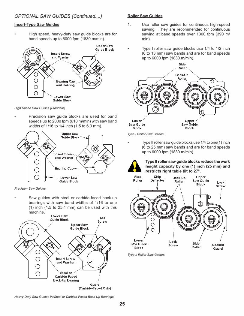
OPTIONAL SAW GUIDES
1. Itispossibletoequipthemachinewithprecision,heavy-duty,highspeed,insert-typesawguidesorrollersawguides.
UNIVERSAL CALIBRATED WORK FIXTURE (Continued....)
25
Insert-Type Saw Gu�des
• Highspeed,heavy-dutysawguideblocksareforbandspeedsupto6000fpm(1830m/min).
High Speed Saw Guides (Standard)
• Precision saw guide blocks are used for band speedsupto2000fpm(610m/min)withsawbandwidthsof1/16to1/4inch(1.5to6.3mm).
Precision Saw Guides.
• Saw guides with steel or carbide-faced back-upbearings with saw band widths of 1/16 to one(1) inch (1.5 to 25.4 mm) can be used with thismachine.
Heavy-Duty Saw Guides W/Steel or Carbide-Faced Back-Up Bearings.
Roller Saw Gu�des
1. Use rollersawguides forcontinuoushigh-speedsawing. They are recommended for continuoussawing at band speeds over 1300 fpm (390 m/min).
• TypeIrollersawguideblocksuse1/4to1/2inch(6to13mm)sawbandsandareforbandspeedsupto6000fpm(1830m/min).
Type I Roller Saw Guides.
• TypeIIrollersawguideblocksuse1/4toone(1)inch(6to25mm)sawbandsandareforbandspeedsupto6000fpm(1830m/min).
Type II roller saw gu�de blocks reduce the work he�ght capac�ty by one (1) �nch (25 mm) and restr�cts r�ght table t�lt to 27°.
Type II Roller Saw Guides.
OPTIONAL SAW GUIDES (Continued....)

26
ADJUSTABLE ANGLE SAW GUIDES
1. Thesesawguidesallowstorotatethesawbandasetangleof45°and90°fromtheregularoperatingposition.
Adjustable Angle Saw Guides.
2. To adjust: (a) Pull the spring plunger out until it disengages;(b)Turnthehousingtotherightuntilitreachesthe45°presetstopuntilthespringplungersnapsbackintoplace:(c)Turnfurthertotheright,itwillsnaptothe90°presetstop.(d)Operatethemachineatbandspeedsunder1500fpm(450m/min).
DUST SPOUT
1. This option is located just below the worktable on therightsideofthemachineframenearthelowersawguideandattachedtoacollectionsystemfordisposalofchipsandotherwastematerials.
EXTRA WORK HEIGHT
1. The factory installed extra work height allowsmaximumcuttingcapacityupto30inches(762.0mm).Machineswiththisoptionhaveanauxiliarypostsupport,plusaslightlydifferentframeweldment,postguarding,andpostelevatinghandwheelfromthoseshownelsewhereinthismanual.
2. Roller saw guides are adjusted as follows:
• Selecttherollerswhichmatchthewidthofsawbandtobeused.Next:(a) Place one (1) back-up roller (has a rear flange) and one (1) side roller in upper guideblock;(b) Place one (1) back-up roller and one(1)siderollerinthelowersawguideblockinoppositepositionoftheupperguide;(c)Attachtheupperrollerguidetothepostandthelowerrollerguidetothekeeperblock.
• Place the saw band over the upper and lower bandwheels.Next:(a) Adjust the saw band tension; (b) Loosen the roller lock screw; (c) Bring therollerstowardthesawbandbyturningtheeccentricbearingshaftwithascrewdriver.Therollersshouldbe just free enough to turn without moving the saw band.
The bear�ngs w�ll overheat �f the rollers are too t�ght aga�nst the saw band. Conversely, rollers that are too loose may cause the saw band to wobble and affect cutt�ng accuracy.
• Tighten the roller lock screws to prevent theeccentricshaftfromturningandchangingtherolleradjustment.
90°SAW GUIDE BRACKETS
1. Thesebracketspermitcuttingmaterialslongerthanthemachine'sregular throatcapacity. Install theupperandlowerbracketsasshown.Thenthesawguideblocksaremountedtothebrackets.
90° Saw Guide Brackets.
2. Whenthesebracketsareused,besureto:(a)Installthecorrectsizesawguides;(b)Installthesawbandsothatitistwisted90°;whenitpassesthroughthesawguideinserts;(c)Operatethemachineatbandspeedsunder1500fpm(450m/min).
OPTIONAL SAW GUIDES (Continued....)

27
BAND FILING
Bandfilingoptionisusedonbandwheelswithcrowned rubber t�res only.
1. There are standard and long file guides available. Each set consists of a file guide back-up assembly, plus1/4inch(6.3mm),3/8inch(9.5mm),and1/2inch(12.7mm)guides.
Set-Up
1. Remove thesawband,sawguides, tablecenterplate,andpostguard. Then: (a) Mount the file guideback-upsupporttothelowerkeeperblock;(b) Install the upper file guide to the post.
File Guide Set-Up.
2. Lowerthepostuntilitwillclearthestockthickness.Post height above stock should be: (a) Not over two(2)inches(50.8mm)fora1/4inch(6.3mm)file band; (b) Not over four (4) inches (101.6 mm) for 3/8 inch (9.5 mm) and 1/2 inch (12.7 mm) file bands.
Longer file guides permit filing seven (7) inch (177.8 mm) thick stock with a 1/4 inch (6.3 mm) file band, oreight (8) inch (203.2mm) thickstockwith3/8inch (9.5 mm) and 1/2 inch (12.7 mm) file bands.
3. Install the upper file guide and lock it firmly to the post with the knurled thumbscrews. Insert thespecialtablecenterplate(roundholeattheendofitsslot).
Jo�n�ng F�le Band
1. Place the file band around the bandwheels and insertone(1)endthroughthetablecenterplate.Theband'scuttingedgesshouldpointdownward.
2. Holdtheyellowlockrivetsegmentinyourlefthand.Then:(a)Depressthespringsteelbandtipheldintherighthand;(b)Allowtherivetheadtoslipintotheslottedholeandslideintotheslot'ssmallend;(c) Straighten the file band to allow the spring steel endtosnapoverthedowel.
Joining File Bands.
F�le Band Track�ng and Tens�on�ng
1. Adjust the upper bandwheel's tilt angle (if necessary) so that the file band tracks on the center of the wheel tire.Then:(a) Check to see that the file band is in alignment and passing freely over the file guide supports;(b)Applythesametensionasindicatedfor a 1/8 inch (3.2 mm) wide carbon saw band.Avoidexcessivefilebandtensioning.
Internal F�l�ng Set-Up
1. Release file band tension. Next: (a)Removethefile band from around the bandwheels and separate it by bending the joint to approximately 12 inches (304.8mm)radius.
2. Use your left forefinger to depress the front end of theyellowsegment.Next:(a)Useyourrightthumband forefinger to disengage the dowel; (b)Slidethelockrivettotheslot'sopenendandremoveit.
3. Run the file band through the stock and reassemble it.Next:(a) Place the file band around the bandwheels; (b)Applytensionandcheckalignment.
F�l�ng Operat�on
1. Place the transmission gear shift lever in "low" range beforestartingthesawbanddrivemotor.
2. Keep these operating points in mind: (a) Keepthe files clean; (b) DO NOT file when the teeth are loaded; (c) Filing can be performed withoutcoolantapplicationifthelayoutlineswillbeeasiertofollow.
3. Clean the file band with a file card and coil it into nomore than three (3) loopsbeforeplacing it instorage.

28
BAND POLISHING
Band pol�sh�ng opt�on �s used on bandwheels w�th crowned rubber t�res only.
1. Three (3) polishing band grain cloths belts areavailableinaluminumoxide:
Appl�cat�on Cutt�ng Gr�t Speeds Grinding 50-300fpm 50 (15-90m/min) Coarse 850-1000 fpm 80 Polishing (260-305 m/min) Fine 850-15000fpm 150 Polishing (260-450 m/min)
Polishing Belt Recommendations.
Set-Up
1. Removethetablecenterplate.Next:(a)Mountthepolishingband'sback-upsupport to thepost(replacing the saw guides); (b) Install the loweradaptertothesawguidekeeperblock.
Polishing Guide Set-Up.
2. Lower the post to approximately four (4) inches(101.6mm)abovethetable.Then:(a)Mountandtrack the polishing band in the same manner as file bands;(b)Tensionthepolishingbandinthesamemannerasfora1/16inch(1.5mm)widecarbonsawband;(c)Installthespecialtablecenterplate(largerslotthanthestandardone).
3. Occasionallyrubgraphitepowderintothepolishingfabrictolubricateandincreasebandlife.Usetheairnozzletoblowawaydustwhilepolishing.
DO NOT use coolant w�th the band pol�sh�ng opt�on.
LASER LINE GENERATOR OPTION
To avo�d eye damage, DO NOT stare �nto the laser beam.
1. Alaserdeviseisusedtoemitalineonthematerialtobecut. This lineshows theapproximatespotwherethecutwilltakeplace.
2. Thedeviseiscontrolledbyaselectorswitchwith"ON"and"OFF"settingsandislocatedonornearthecontrolpanel.Turnthelaser"OFF"whennotinuse.
3. The laser is adjustable to position the laser beam wheredesirable.
4. Whenthelaseristurnedon,awarm-upperiodof3to5secondstakeplacebeforealineappears.Ifthe line is difficult to see, darken the work area to enhancetheline.
5. Removetheprotectiveshippingcapfromthelaserdevisebeforeoperation. Replace theprotectivecapwhennotinuse.