34ASA TECHNICAL NASA TM X-71867 … overall gear ratio is 17.44: 1 reduction. The planet bearing...
36
34ASA TECHNICAL MEMORANDUM NASA TM X-71867 OH-58 HELICOPTER TRANSMISSION FAILURE ANALYSIS by D. P Townsend, J. J. coy: and B. R. Hatvani Lewis Research Center Cleveland, Ohio 441 35 ,January, 1976 an d %. S. Army Air Mobility R&D Laboratory (NASA-TN-1-7 1867) CH-58 HZLICOPTHR h76- 1bdb5 IRANSflISSICN PAILUFE ANALYSIS (NASA) 35 p HC $4.C? CSCL PlC Unclas G3/?5 39994 https://ntrs.nasa.gov/search.jsp?R=19760008977 2018-07-01T02:45:54+00:00Z
Transcript of 34ASA TECHNICAL NASA TM X-71867 … overall gear ratio is 17.44: 1 reduction. The planet bearing...
3 4 A S A T E C H N I C A L M E M O R A N D U M
NASA TM X-71867
OH-58 HELICOPTER TRANSMISSION FAILURE ANALYSIS
by D. P Townsend, J. J. coy: and B. R. Hatvani Lewis Research Center Cleveland, Ohio 441 35 ,January, 1976
an d
%. S. Army Air Mobility R&D Laboratory
(NASA-TN-1-7 1867) C H - 5 8 HZLICOPTHR h76- 1bdb5 IRANSflISSICN PAILUFE ANALYSIS ( N A S A ) 35 p HC $4.C? C S C L P l C
Unclas G3/?5 39994
https://ntrs.nasa.gov/search.jsp?R=19760008977 2018-07-01T02:45:54+00:00Z

I OH-58 HELICOPTER TRANSMISS1ON FAILURE ANALYSIS 6 &fwm~ng Organltat~on CWc +-------I
I NASA Levis Research Center and
1 U. S. Army Air Mobility R&D Laboratory
7 Aurhor(rl
D. P. Townsend, J. J. Coy, and B. R. Hatvani
9 h f w m l n g &pv\~zatf~n Name and Address
/ 11 Contract or Grant No I
8 Pnform~ng Organ~zar~on R q m t No
E-8633 10 Wa-k Unlt No
Cleveland, Ohio 44 135 12 Spnrcrlng n p ~ v am and ~ d d m ~ Technical Men;orandum
National Aeronautics and Space Administration Washington, D. C. 20546
1
15 Supdem~lltary Notes 1 I Prepared for OH-58 Weapon System Manager, U. S. Army Aviation Systems Command. I I S. Louis, [email protected] I
4 16 Abrtran
The OH-58 main transmission gearbox was run a t varying outplt torques, speeds, and oil cooling rates. The gearbox was subsequently run to destruction by draining the oil from the gearb<rx while operating a t a speed of 6200 rpm and 36 000 inch-pounds output torque. Primary cause of gearbox failure was overheating and melting of the pane t bearing aluminum cages. Complete
1 failure of the gearbox occurred in 2% minutes after the oil pressure dropped to zero. The gear- box airjoil cooler has sufficient cooling capacity marcin for hot day takeoff conditions a t a 117 percent power rating. The ~l ternat ing and maximum st resses in the gearbox top case were approximately 10 percent of the endurance limit :c? the material. Deflection of the bevel gear a t 67 000 inch-pounds output torque indicate a marpnal stiffness for the bevel gear supporting system.
17. Key Wards !Suggested by Author(%;: 18 D~str~but~on Statefncnl
Unclassified - unlimited
19 Saur~tv Clan~f. (of this report)
Unclassified
' For sale by tnr Nallonal Technical lnformat~on Servlce. Sprlnefleld Vlrgtnla 22161
10 Securltv Clrrc~: (of thls pagel
Unclassified 21. No of P lpn 22 Price'

OH-58 HELICOPTER TRANSM3SIOnT FAILURE ANALYSIS
by D. P. Townsend, J. J. Coy, and B. R. Yatvani
Lewis Research Center and
U. S, Army Air Mobility R& D Laboratory
INTRODUCTION
The OH- 58 i s a U. S. Army Light Observation Helicopter (LOH) (fig. 1).
The aircraft can carry up to five passengers and crew combined It has a gross
takeoff weight of 3000 pounds. It is currently powered by a 317 shaft horsepower
(SHP) turbojet engine (Allison Model Specification 803-A). The U. S. Army Aviation Systems Command (AVSCOM) has undertaken a pro-
gram to upgrade the current OH- 58 Light Observation Helicopter for utilization
as an Interim Scout Helicopter (ISH) until such time a s an Advanced Scout Heli-
copter becomes available. The rnissior. of the Interim Scout will be primarily to
acndre designate targets for engagement by Army armed helicopters
(AH- 1Q Cobra- TOW and AH- 1G Cobra) and secondarily to gather intelligence for
the ground commanders. One of the key requirements for the accomplishment
of this mission is survivability of the aircraft in hostile environments.
Helicopter operations in combat have shown that the transmission system is
highly vulnerable to ballistic damage. One of the most vulnerable parts of the
helicopter drive system is the lubrication and cooling system. Any type of ballis-
tic hit in the lubrication system can result in a loss of lubricant to the gears and
bearings in the transmission. If the supply uf oil to the transmission is inter-
rupted, the transmission may fail and seize thus l imting the time the pilot has
to return safely to base o r tu make a forced landil~g.
The OH- 58 Weapons System Manager requc sted NASA- Lewis Research
Center's assistatlre in upgrading the current OH-58 main rotor transmission in
performance and survivabil~ty. As a result of this request, a cooperative program
was developed involving the OH-59 Systems Office, Corpus Christi Army Depot and
Lewis Research Center. The NASA agreed to provide the following in support of
this program: 1. Necessary professional and technical support personnel to instrument a d
perform testing on an OH-58 gearbox at Corpus Christi Army Depot to obtain
baseline data on th: gearbox. 2. Analysis of the data by personnel of the NASA Bearing, Gearing, and
Transmission Section.

3. Written recommendations by the Lewis F-esearch Center to the OH-58
System Manager for the incorporation of technology necessary to upgrade the
perforn~ance and survivability of the gearbox.
Tests of an OH-58 main rotor transmission were co~~ducted by the NASA
Lewis Research Center at the U. S. Army's Corpus Christi Army Depot under
simulate~l field conditions. The results of these tests and recommendations a r e
reported .lerein.
OH- 58 HELICOPTER MAIN TRANSMISSION
The OH- 58 main transmission (fig. 2) i s rated for 270 horsepower continuous
duty and 317 horsepower a t takeoff for 5 minutes. The 100 percent input speed is 6200 rpm. The output speed is 354 rpm (ref. 1).
The input shaft drives a 19 tooth spiral bevel pinion. The pinion meshes with a 7 1 tooth gear. The input pinion shaft is mounted on triplex ball bearings and one roller bearing. The 71 tooth bevel gear is carried on a shaft mounted in du-
plex ball bearings and one roller bearing. The bevel gear shaft drives a floating sun gear which has 27 teeth. The power is taken out through the planet carrier.
There a re three planet gears of 35 teeth which a r e mounted on spherical roller
bearings. The ring gear (99 teeth) is splined to the top case and therefore i s sta-
tionary. The overall gear ratio is 17.44: 1 reduction.
The planet bearing inner-races and rollers are made of AISI &I-50 steel.
The outer-races and planet gears, which a r e integral, a r e made of AISI 9310.
The cage material is 2024-T4 aluminum. The gear shaft duplex bearing mate-
rial is CVM 52CB. All other bearings are made of AISI 52100 with bronze cages.
The sun gear and ring gear material is Nitralloy N (AMS6475). The input spiral bevel gear-set material is ALSI 9310. Lubrication is supplied through jets lo-
cated in the top case. An external air/oil cooler is used (fig. 2(b)).
TEST PROCEDURE
The OH-58 gearbox was placed in the Corpus Christi Army Depot OH- 58 test
stand after being fully instrumented (fig. 3). Figures 4 and 5 show the control
room adjacent to the test cell. The test stand was calibrated and the gearbox
filled with MIL L23699 oil. The gearbox was operated for several hours to
check out the instrumentation and to check for oil leaks, slipring operation and input shaft balance condition. This running time also gave additional break-in
time for the new gearbox.

The gearbox was subsequently operated a t 32 different test conditions with
data taken after the oil temperature had stabilized. The temperature was con- ;idered stabilized when it changed less than 0. lo in 1 minute. The tests were
run at output torque levels ranging from 2500 to 67 200 inch-pounds, nil-out tem-
peratures ranging from 175' to 245' F, input speeds of 5550 (90 percent normal),
6200 (normal) and 6820 (110 percent normal) rpm. Oil-out temperature was con- trolled by blocking the airflow to the a i r oil cooler located on the transrnissi~n,
A cyclic tect was conducted while contjlluously recording data. The test was started at zero ,peed and 2000 inch-pounds output torque. The speed was in-
creased to 6200 rpm. Subsequently, the output torque was increased to 62 400
inch-pounds. While maintaining speed, the torque was decreased to 12 OCG inch-
pounds. The speed was reduced to zero rpm and then increased to 6200 rpm. The oil-out temperature was set at 200' F at the beginning of the test.
The llnal test run was the survivability test, The output torque was set a t
36 000 inch-pounds (75 percent power rating), the input speed was 6200 rprn and
the initial oil-out temperature was 200' F. The oil was drained from the bottom
of the gearbox The time from starting oil drain to zero oil pressure was a p proximately l2 minutes. It took another 1/2 minute for all the oil to drain from
the gearbox. The test was stopped at approximately 30 minutes from the time
the oil drain was opened.
DATA ACQUISITION
Instrumentation provided for the OH- 5s gearbox tests consisted of 23 iron-
constantan thermocouples, four accelerometers, three strain gages and three
proximty probes. The locatf on cf the instrumented components are shown in
figure 2. Two sflver brush sliprings were used to obtain data from the input
and output shafts. Leads through the input shaft were used to obtain signals from a strain gage located on a pinion tooth and four thermocouples, one on a
pinion tooth and three on the inner races of the three pinion shaft bearings. The output shaft slip ring was used to obtain signals from three thermocouples, one
of which was located at the mast bearing inner race, the second was located
close to the planetary support bearing inner race and the third was located close
to the inside diameter of the sun gear. It was originally planned to locate a
thermocouple on the planet bearing, however, the method of gearbox assembly
did not permit a thermoco~ple at this location.
Thermocouples were also provided to measure temperatures at the following
locations: the input shaft seal; the outer race of the two inner pinion bearings;
the pinion roller bearing outer race; the oil splash off at the pinion mesh; the

outer races of the three bevel gear support bearings; the outside edge of the ring gear; three locations on the transmission housing the oil inlet; the oil out- let; the oil sump; and the test cell ambient air. The 23 temperatures were re- corded on a multichannel digital readout-recorder which would print all temper- atures in approximately 20 seconds.
Accelerometers were mounted a t three locations on the transmission case. One accelerometer was placed on the input shaft slipring. The accelerometer signals were recorded on magnetic tape for both the cyclic test and the surviva- bility test,
The acceleration signals were examined at the Lewis Research Center. The
raw time signals were played back from the magnetic tape. The time signals were complex waveforms due to many harmonic frequencies being present in the signals. Therefore, the raw signals were analyzed in two ways. First, the peak amplitude of the acceleration was plotted against time. Second, the frequency spectrum at four different points in time was determined.
Frequency spectrums were generated by using a real-time spectrum analyzer. Frequency spectra were obtained for the time periods of 0 to 1 minute, 7 to 8 rnin- utes, 15 to 16 minutes, and 27 to 28 minutes. The data was averaged 256 times and 800 frequency points were used for 0 to 5000 Hz. The frequency resolution was better tban 10 Hz. Spectrums for the ring gear and input pinion @To. 1 and 2
accelerometers) a re reported herein. The acceleration data can be helpful in determining the onset of failure in a
transmission. The accelerometer responds instantmeously to mechanical vibra- tions in the gearbox which may be indications of failure in progress. Reliance on thermocouples as detectors of impending failure is not satisfactory because temperature response is too slow. The very short period of damage causing activity within the gearbox may be insufficient for temperatures to change. An additional drawback is that temperature gradients exist in the gearbox and hot spots a r e very much localized. Unless a thermocouple is very strategically placed, it will be too far away from the damaged area to record the effects of damage in the critical points of the transmission. On the other hand, vibrations a r e transmitted very rapidly and variations in frequency content of the signals give a measure of changes in the mechanical structure a s fast a s they occur.
Three inductance type proximity probes were located a t different locations to measure various gearbox deflections and load conditions. One was mounted inside the gearbox, close to the top side of the bevel gear at the point where the pinion meshes with the gear, to measure bevel gear deflections under load. An- other was mounted close to the transmission housing adjacent to the ring gear to measure housing deflections from the planet gear 1, i on the ring gear. A third

proximity pmbe was mounted close to the output shaft to measure output shaft
motion.
The outputs of the three proximity probes wre connected to drivers n ~ t h a -18 V dc power supply and to differential amphfiers to amplify the signals anc'
then to the 14 channe! F M tape recorder with ?rovis~ons to monitor the signals on 2 four channel oscilloscope.
Three strain gages with temperature compensanng gages were also located
on the various parts of the OH-58 transmission. One strain gage was located
on the top case adjacent to and parallel to the ring gear and another was located
on the slant section of the top case perpen&cdar to thc ring gear. I'hese gages
were used to measure the case deflection and s t ress caused by the planet gears
under load. The third strain gage was m~unted at the small end of cne of the
pirion teeth, and connected through the input shaft s1:pnng. The st ra in gages
were connected to a bridge circuii and strain gage amplifier and to the 14 chan-
nel F M tape recorder wiih an additional connect~~in tcb mo~-.itir the signals oc the
oscilloscope.
The 14 channel EM tape recorder was used to record the four accelerometer
signals, three proximitor signals, three strain gage signais, the input and out-
put shaft torques and a 1 volt 1 kHz reference s~gnal. The four channel oscillc- scope was used to monitor the output signals in order to determine their con&-
tion. All wiring, including the thermocouple .,I nng, were shielded cables and
were from the test cell to the control room through shielded conduit to pre-
clude the possibility of signal jnterierence.
RESULTS AND DISCUSSION
Cperating Temperatures
Figure 6 contains the temperatures of the various transmission ,umponents
a s a function of output torque. The respective numbers in the figurll indicate the location of the thermocouples in figure 2(a). The oil-out temperature was
maintained at 200' Y and the input speed was 6200 rpm, The temperature r e corded for the 67 000 inch-pound torque (140 percent power rating) was not sta-
bilized due to the short time at which this overload con&tion (140 percent torque)
was maintained. The highest temperature was recorded for the pinion seal which was 228' F at an output torque of 62 400 inch-pounds i 130 percent power rating).
In order to determine the transmission oil-out stabilization temperature, the
transmission was run with different output torque conditions while the oil cooler
was either completely blocked, partially blocked o r completely open, The re-
sults of these tests a re summarized in table I and shown In fi@:-t: 7. The maxi-
mum oil-out temperature obtained for zero percent and 50 percent oil cuoler

blockage at 56 000 inch-pounds output torque (117 percent power rating) was 197' and 210' F, respectively. When the oil cooler was completely (100 per- cent) blocked, the transmission stabilized at an oil out temperature of approd- mately 246' F at an output torque of 48 000 inch-pounds (100 percent power rating). The 173' F oil outlet temperature a t near zero output torque and 100 percent oil cooier blockage indicates excessive heat generation which is prob- ably caused by excessive oil churning resulting from too much oil in the gearbox.
'I%e ambient temperature condition was approximately 85' F so that for a hot day condiiion having a 125' F ambient temperature, the gearbox should sta- bilize at approximately 240@ and 250' F ci l outlet temperature for the completely open and 50 percent blocked conditions, respectively. These data indicate that the oil cooler has adequate inargins for hot day takeoff corlditions at 117 percent power rating.
At a torque level of 36 000 inch-pounds and a speed of 6200 rpm the drain plug a t the bottom of the travlsmission housing was r e m ~ v e d a id the oil in the transmiseion was allowed to drain out. The results of this test are shown in figure 8 wherein the component tempera-tures a re shown a s a function of time. Time zero is the time at which the oil drain plug was remdved.
At 1.5 minutes after the oi l bega-n to drain from the transmission, the oil pressure drbpped to zero. A t this point, the temperatares of the variovs com- ponent~ began to r ise reflecting a lack of cooling oil.
After spproximately 7 minutes, there is an abrupt change in the rate of tem- perature i n c e a s e which is more iloticeable at the lnput pinion where tempera- tures reached 490' F on the pinion gear. This increasea temperature was caused by the loss of the first planet bearing aluminum cage (fig. 9) causing a torque in- crease on the irput pinion and some molten aluminum co~t ing the pinion teeth
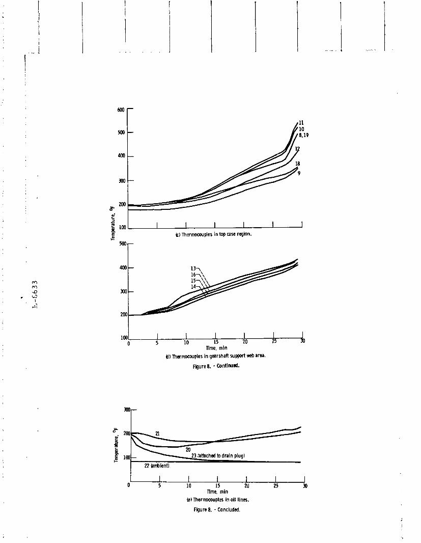
(fig. 10). F i g c e 8(c) shows an increase in temperature in the planet gear area at ap-
proximately i3 minutes. The rate of :ncrease of the pinion temperatures slowed until at approximately
14 minutes the rate began to increase again (figs. 8(a) and (b)). These increases in temperature. were caused by addittonal planet bearing caLes melting which allowed the spherical rollers in the planet gear bearings to tcmble and slide within the bexings (fig. 11).
At appro.dmately 27 minutes there is an ~dditional increase in the rate of temperature ridn a s seen in the nlanet and (fig. 8(c)), the p i n i o ~ area (figs. 8(a) and (b)) and to a lesser extect in the be-:el gear bearing area (fig. 8(d)). At this point in time the y e a r h x is approaching complete failure. At thme tempera- tures, the p! met g ~ a r s have very little strength. The lock nut on the planet bearing was being machined by the 'bevel gear bolt heads (fig. 12). The pinion

gear was approaching 600' F. The temperature near the sun gear and planetary carr ier bearing was increasing rapidly indicating a much higher temperature in the sun gear and planet gears. Subsequent examination of the planetary bearings and gears indicates that they reached temperatures in excess of 1100~ F.
Temperatures in the ai; system were measured and a re shown in figure 8(e). A thermoco~ple placed near the transmission recorded the ambient temperature of the test cell. It was 84*1° F for the duration of the test. The thermocouple attached to the oil drain measured the slow temperature decay to ambient condi- tions from the time the drain plug was removed. The two thermocouples in the oil line measured the initial reduction in temperature that resulted from the dis- appearance of hot oil in the lines. The temperature later rose again in response to the heating by conduction from the hot gearbox
Dynamic Failure Analysis
7igure 13 shows the record of the four acceleration peak amplitude levels a s a function of elapsed time from the moment the lubricant drain was opened. The respective numbers in the figure indicate the location of the accelerometers, shown in figure 13. The accelerations a r e plotted on a logarithmic scale. Accel- erations were measured (1) in the horizontal direction on the top case in the re- gion of the ring gear, (2) in the horizontal direction on the lower case near the input spiral bevel pillion gear shaft, (3) in the horizontal direction 03 the b t t o m case in the plane of the spiral bevel gear, m d (4) in the vertical direction on the outboard end of the slipring unit. The acce' .ration peak levels were lowest on the slipring unit and highest on the top case near the planetary ring gear. It was expected that the highest vibrations would be in the region of the ring gear on the top case. This is because the planet spur gears a r e the heaviest loaded gears. Also, the spur gears should have higher dynamic loads than the spiral bevel
gears. The f irs t indication of failure occurrence in the gearbox was at zero plus
7 minutes. The vibration level increased very abruptly, by approximately 80 percent, at all three locations on the transmission. This rapid buildup and subsequent sustained level of vibration was an indication of a cage failure in the planet gear bearings. The thermocouples located at the spiral bevel mesh exit airstream showed a rapid increase to 360' F in the 2 minute time period follow- ing this event. The thermocouple located on the pinion tooth showed a much larger increase in temperature to 490' F in the same time period. The rapid increase in these temperatures indicated the sudden increase in the torque pass- ing through the input gear mesh caused by the cage loss in the planet bearing. After 9 minutes, the vibration levels decreased briefly. Also, the input pinion

gear tooth temperature decreased t o 455' F in the 9 to 13 minute time interval. This brief decrease in temperature was probably caused by the s i t i n g of cage debris from the planet gear bearing cavity.
At 10 minutes, vibration amplitude began increasing again, with the peak level o ~ c u r r i n g a t 14 minutes. At this time, a level of 40 g' s was observed on the ring gear. This was about 230 percent of the level a t time zero. This vibra- tion activity was caused by the breakup of the second and third aluminum planet gear bearing cages. Once again, the vibration level decreased while the temper- atures continued to r ise at a steady rate. The accelerometer mounted on the lc ger case at location 3 dropped off at 18.5 minutes. The high temperature had weakened the mounting cement. During the time from 17 to 27 minutes the ac- celeration levels at the number 1 location were erratic and stayed between 10 and 16 g's. During this time, the rollers were skidding and their axes were badly skewed. The drag torque offered by the damaged bearings was sufficient to cause the inner races to turn on the planet bearing posts. The cotter key was sheared on two of the bearings and the shaft nut was being turned by the bearing inner race.
At 27 minutes the bibration levels again increased at the ring gear to the 30 to 40 g level At th: t time the shaft nut was being struck by the bevel gear sup- port bolts which were immediately below and on the gear shaft. The relative rotatiocal speed of the planet carr ier and the gear shaft was 1300 rpm. The re- taining nut was rapidly machined away by the gear shaft b o b . Subsequently, an inner race of one of the spherical roller bearings came off the shaft allowing the spherical rollers to drop out of the bearing. One of t,he rollers wedged into the ring gear-planetary gear mesh. This caused the plaret car r ier to lock up. As a result, the teeth on the sun gear were destroyed by the torque overload. At 30 minutes after the oil drain was opened, complete transmission failure oc- curred.
Spectrum Analysis
The results of the spectrum analysis a r e shown in figure 14 for the input pinion location and in figure 15 for the ring gear Iccation. Figures 14(a) and 15(a) show the frequency content of the normal transmission. The next three time periods at which a spectrum plot was obtained were selected in order to show the frequency content of the signal immediagely after the several stages of high amplitude vibrations were observed. A comparison of the spectra for these time periods show how the transmission vibration signature changes as the shut- down failure p:nt i s approached.
The area under the curve on the spectrum plot is a function of the RMS value of the acceleration signals. But the most important items of interest a r e the

frequencies at which the major strength of the vibration is centered. The two dominant sources of vibration a re the input spiral bevel gear mesh frequency (1963 Hz) and the planet-sun-ring spur gear meshing frequency (586 Hz). At time zero the strongest amplitude i s caused by bevel gear mesh. There a re first and second harmonics present. Theee a re denoted by the circles on the plots. The spur mesh fundamental frequency and the next seven harmonics a r e visible also. These a r e denoted by the inverted triangles. The presence of higher harmonics is an indication of the degree of deviation from a sine wave type of acceleration signal. Also visible on the plots near the major frequen- cies a re several subordinate peaks. These a re the side-band frequencies. They a r e introduced by the modulating effect of h e lower frequency components. The modulation is caused when the gear mesh v'--ration grows stronger a s the planet approaches the accelerometer and then again diminishes a s the planet passes by the accelerometer.
The spur gear mesh frequency is 586 Hz and the planet paez frequency is
18 Hz. Therefore, side band responses oi 586*18 Hz a re expected. The higher harmonics may also have modulation sidebands. Another source of modulation is the rotational frequen,y of the planet gears whch is 16 Hz. However, this will produce sidebands which a re only 2 Hz away from the sidebands produced by the planet pass frequency, This difference is beyond the resolution of the s?ectrum analyzer. Modulation sidebands a r e also visible at 1963*103 Hz. They a r e caused by the eccentricity of the pinion gear which makes the tooth impact loads vary in intensity a s the gear rotates. It was known that the input shaft was not well balanced and this is the primary cause of these sideband re- sponses. Similar sidebands also appear on the second harmonic of the spiral bevel gear mesh frequency (2 x 1963*102 Hz),
After 7 minutes of operation two classes of change in the transmission signa- tures a r e noticed by comparing figurcs 14 (b) and 15(b). The first is an increase in the amplitude of the 888 Hz frequency line. This is the frequency generated if it is assumed that one row of the rollers in the planet bearing has cage debris on it. The pulsating effect t.hat this would have on the input mesh is seen by the presence of upper and lower side band response at 1963*888 Hz. This is caused by the periodic variation in torque when the rollers roll over the cage debris.
The second general effect i s that the percentage increase in the spiral bevel related amplitudes wss approximately 75 percent. No significant increases in the spur mesh related amplitudes were observed. This indicates that gear dy- namic loading at the spiral bevel mesh h ~ r ! increased, but the gear loads and meshing action at the sm planet and planel ; ing gear meshes were essentially normal. These changes in the transmission signatures indicate that planet bear- ing degradation began at the 7 minute mark. The sudden appearance of a frequency
component a t 1550 Hz was also observed when comparing figure 14 (b) with figure
14 (a). It was speculated that this was a fourth lower side band of the bevel mesh fundamental frequency (1963 - (4 x 10³)). The immediate saurce of this compo- nent is unknown.
Figures 14(c), 14(d), 15(c), and 15(d) iqdicate that two primary changes in the nature of the spectra have occurred. The first is the large increase in the fundamental spur mesh frequency and its harmonics. This indicates that imper- fect mesh action is occurring at the sun-planet-ring gear meshes. Secondly, there is a large amount of sideband activity around the spur mesh requencies. The buildup of sideband amplitudes indicates that the planet bearings were in very poor condition. The increased runout and misalignment of the bearings caused by cage loss and roller skewing is the cause d the modulation. There is also s
large level of broadband accelerat~on that is especially noticeable on figure 14jd). This is caused by the skidding of t.he badly misaligned rollers in the planet bear- ing. The amplitudes of accel~rat ion a re very low in the 2 to 5 kHz range in fig- 1 5 . This i s attributed to the high temperature (500' Fl softening of the cement used to mount the accelerometer.
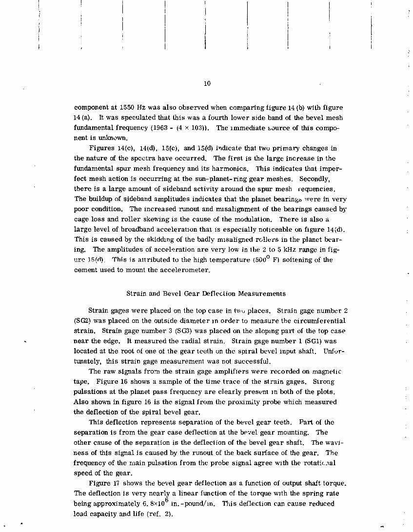
Strain and Bevel Gear Deflection Measurements
Strain gages were placed on the top case in t w ~ , places. Strain gage number 2 (SG2) was placed on the outside diameter In order to measure the circumferential strain. Strain gage number 3 (SG3) was placed on the sloping part of the top case near the edge. It measured the radial strain. Strain gage number 1 (SG1) was located at the root of one of the gear teeth on the spiral bevel input shaft. Unfur- tunately, this strain gage measurement was not successful.
The raw signals from the strain gage amplifiers were recorded on magnetic
tape. Figure 16 shows a sample of the time trace of the strain gages. Strong p-dsations a t the planet pass frequency a r e clearly present In both of the plots. Also shown in figure 16 is the signal from the proximity probe which measured the deflection of the spiral bevel gear.
This deflection represents separation of the bevel gear teeth. Part of the separation is from the gear case deflection at the be- el gear mo~mting. The other cause of the separation is the deflection of the bevel gear shaft. The wavi-
ness of this signal i s caused by the runout of the back surface of the gear. The frequency of the main pulsation from the probe signal agree with the rotatic-la1 speed of the gear.
Figure 17 shows the bevel gear deflection as a function of output shaft torque. The deflection i s very nearly a linear function of the torque wlth the spring rate
6 being approximately 6. 8x10 in. -pound/in. This deflection can cause reduced load capacity and life (ref. 2).

Figure 18 summarizes the s t ress values that were obtained from the strain gage measuremellts. The s t ress results a r e reported a s having a mean value m d a peak-to-peak fluctuating value. Under all parametric temperature and torque conditions, the mean stresses on the top case did zat exceed 3350 psi compres- sion. The fluctuating peak-to-peak values were less ".an 2700 psi.
For the circumferential o r hoop siress on the outside diameter of the top case, the mean s t ress was always less than 800 psi compression. The fluctuation component of the stress was less than 2400 psi. The upper case was forged from 4032-T6 aluminum alby. The room temperature tensile strength is 55 000 psi, the yield strength is 46 000 psi, and the endurance hmit from R R Moore tests
8 is 16 000 psi for a life of 5x10 cycles (ref. 3). The worst condition of fluctuating stress was less than 10 percent of the endurance limit of the material.
GENERAL OBSERVATIONS
The major weakness to the survivability of the OH-58 main transmission was the cages of the spherical roller bearing: of the three planet gears of the planet carrier. These cages are made of 2024-T4 aluminum having a melting point of 1125' to 1150' F. The maximum useful 'smperature of this aluminum alloy is
300' to 400' F. As a rc?sult, the first and most mandatory change i s to substitute silver-plated cages made out of vacuum remelted AMS 6414B which is a low car- bon steel. These cages retain adequate stre,lgth to approximately 700' F. Cages made out of thia . laterial have been run continuously at temperatures of 425' F
6 and at speeds of 8x10 DN (where DN is a speed parameter defined as the prod- uct of the bearing bore in mm and the'bearing speed in rpm) for a cumulative time period of approximately 75 000 hours (ref. 4).
The lower gearbox assembly which comprises the i.*put spiral bevel gear sei -?as rlot damaged during the survivability test (fig. 19 ). The maximum tempera- tures within the lower gearbox assembly were in the range from 325' to 525' F.
It would appear from the condition of gearing and bearing components after the su~dvabil i ty test that the materials were adequate for the time duration of the test which was 30 minutes. However, for longer time periods both the bearing and gear materials may be marginal. Consideration should be given to replacing all the bearing materials within the t,ransmission w. ~ c h a re AISI 52100, CVM
52 CM, and CVM AISI M- 50 with vacuum- induction melted vacuum-arc remelted (VIM-VAR) AISI M-50 steel. This steel has high temperature bearing operating capability to 600' F (refs. 5 and 6) and rolling-element fa.tigue lives of approd- mately 20 times current design requirements (ref, 4). Manufacturing specifica- tions incorporating the techqology br reference 4 is contained in referenze 7.

Insufficient gear data exists to recolzlmend a high-temperature gear material in place of the AISI 9310 steel currently being used for the bevel gear set. Endur- ance testing of currently used and prospective gear materials are being perhrmed at the NASA-Lewis Research Center. Out of those potential high-temperature ma- terials studied, Super Nitralloy exhibited lives exceeding AISI 9310 (refs. 8 and 9). Nitralloy N (AMS 6475) is a material which also has high temperature ch~racter is - tics but has not been endurance tested in rolling-element fatigue. However, this material has found acceptance a s a gear material and is used for the sun and ring gear matenal in the OH-58 transmission. Consideration should be given to changing all t l e gear materials except a s noted below to Nitrdloy N (AMS 6475).
Because the outer race of the planet bearings is integral with the planet gear, there is a requirement to have a case depth of 0.040 inch prior to grinding the race surfaces. This results in a final case depth of 0.030 inch. Since the case depth of nitrided steels such a s Nitralloy K is approximately 0.020 inch, this class of steel is precluded from use a s the planet gear. AISI 9310 which is the current planet gear material does not have sufficient hot hardness characteristics to assure continuous operation a s a bea.ring material at temperatdres much above 300' F. As a result, another case carburized materlal must be considered. Be-
cause of a lack of rolling-element fatigue data with carburized steels having high- temperature capabilities no recomlnendatlons can be made for a substitute mate- rial at this time. Testing of various carburized materials a re currently being performed by the NASA- Lewis Xesearch Center.
Two steps can be taken to reduce heat generation at the planet gears. The first and most obvious step is lo reduce the load on the plalet gears. This step can be accomplished by replacing the three planetary system with a four planetary system. This will reduce the load for each plarut gear-bearing combination by 25 percent.
The second would be to replace the spherical roller bearings with crowned cylindrical roller bearings. This can result in reduced heat generation within the bearing by as much as 30 percent (ref. 1G). However, this step would require rigid stradle mountings in place of the overhung mountings currently on the plane- tary spider. However, there is a probability that gyroscopic induced thrust loads may be unacceptable for these bearing. As a result. further transmission bench testing would be required.
The cyclic s t ress levels in the top case do not appear to be of sufficient mag- nitude to cause fatigue of the top case. However, the transmission tests were not conducted under actual flight conditions. The amplitude of the cyclic stresses may be higher in flight than in the tests reported herein. It i s therefore recom- mended that strain gages be placed on a transmission installed in an aircraft and data be rerorded during flight operation.

A critical area within the transmission i s the main mast bearing retention
housing in the upper gearbox. This housing supports the weight of the helicopter. The casing of the upper gearbox is made out of 4032-T6 aluminum. At room tem- perature the tensile strength of this material i s 55 ksi. At 300' F, the tensile strength is 37 ksi. It is 13 ksi at 400' F (ref. 11). Hence, at room temperatures much above 300' F this material becomes marginal f o r the purpose for which it was intended. The maximum measured temperature of the mast bearing retention housing was approximately 348' F. This temperature is considered acceptable jmder tire operating conditions reported for the material to assure survivability for 30 minutes.
Field experience has shown thet the mast bearing which is made from CVM AISI M-50 has produced operating fatigue lives less than 1000 hours in many cases. The bearing life can be improved by using VIM-VAR AISI M-50 a s previously dis-
cussed. However, should the transmission 'be uprated above 375 HP this bearing should be increased in size in ~ r d e r to increase its l ~ a d capacity and life. In ad- dition, the gearbox top cover should be strengthened in order to assure its capabil- ity of sustaining high loads.
Increased loading on the transmission above 375 HP will result in increased
separation of the bevel gear set. As discussed in the t.ext, this will result in a re- duction in the load capacity of the bevel gear set, and thus life. As a result, con- sideration should be given to increase the stiffness of the bevel gear mounting and the bevel gear shaft.
SUMMARY OF RESULTS
The OH-58 maill rotor t ransmiss i~n was run on the Corpus Christi Army Depot's OH-58 test stand at Corpus Christi, TX a t output torques from 2500 to 67000 inch-pounds and a t inputs speeds of 5580, 6200 and 6820 rpm with varying oil cooling rates. The gearbox was subsequent.1~ run to destruction by draining the oil from the gearbox while operating at a speed of 6200 rpm and 36000 inch- pounds output torque. The following is a summary of the results obtained.
1. The primary cause of failure in the survivability test was overheating and melting of the planet bearing aluminum cages with subsequent loss of m e planet bearing and loss of teeth on the sun gear from excessive temperature and load.
2. The transrnismission air/oil cooler has sufficient cooling capacity margin for hot day takeoff conditions at a 117 percent power rating.
3. Deflection of the bevel gear for output torques up to 67000 inch-pounds (140 percent power) indicates a marginal stiffness for the bevel gear supporting system.

4. The alternating and maximum stresses in the gearbox top cover for output torques up to 67000 inch-pounds (140 percent power) and without helicopter loads were within approximately 10 percent of the endurance limit for the material at room temperature.
5. After oil pressure dropped to zero, the length of operating time until the first planet bearing cage failed was five and one half minutes. The remaining two cages failed in approximately 11 minutes. Complete failure of the transrnis- sion occurred in 28 11'2 minutes.
RECOMMENDATIONS
As a result of evaluation of the test data from the load and temperature sur- vey tests and the survivability tests, the following recommendations are included to improve the gearbox survivability and load carrying capacity. These recommen- dations are listed in the order of importance and generally with the least potential cost impact on any proposed product improvement program.
1. Replace the planet bearing cages and the planetary support bearing cage with silver plated steel cages. This change will give a much needed increased temperature capability.
2. Change the three planet system to a four planet system. This change would reduce the load on each planet bearing by 25 percent resulting in reduced heat gen- eraiion and increased life.
3. Change the spherical roller bearings to cxrEArical roller bearings with rigid stradle mounting to replace the overhung mounting. This change would re- duce the heat generation in the planet bearing up to 30 percent. Further testing would be required.
4. The material for all bearings within the transmission should be changed to VIM-VAR AISI M-50. This change will result in longer bearing fatigue Life and improved elevated temperature operation.
5. Change the AISI 9310 gear material to a high-temperature material for longer life and survivability at high temperature. The specific material to be used should depend on existing endurance data and material availability.
6. Increase the stiffness of the bevel gear support shaft to reduce the amount of separation of the bevel gear under load and increase the power capability.
7. For uprating above 375 HP, the gear box top cover should be strengthened, the mast bearing increased in size, and the bevel gear mounting shoilld be stiffened,
8. The improvements incorporated into an advanced transmission by the project office should be tested to determine the extent of the improvement and transmission reliability.

REFERENCES
1. Anon., Dctailcd Spccificatica fcr Model 206A Light Observation Helicopter
Bell Helicopter Rep. No. 206-947-031, Oct. 30, 1973.
2. Anon., Practice for Speed Reducers and Increasers Employing Spiral Bevel Gearing. AGMA Standard 430.03, Dec. 1963.
3. Clark, D. S. and Varney, M. S. , Physical Metallurgy for Engineers.
D. VanNostrand Co., Princeton, NJ, 1962, p. 436.
4. Bamberger, E. N., Zaretsky, E. V. a d Signer, H., Endurance and Failure 6
Characteristics of Main-Shaft Jet Engine Bearings at 3x10 DN. Proposed
ASME Paper to be presented at 1976 ASME Spring Lubrication Symposium,
Atlanta, GAY May 24-26, 1976.
5. Bamberger, E. N. and Zaretsky, E. V., Fatigue Lives a t 600' F of 120-rnm
Bore Ball Bearings of AISI M-SO, AISI M-1, and WB-49 Steels, NASA TN
D-6154, 1971.
6. Zaretsky, E. V., Anderson, W. J. and Bamberger, E. N., Rolling-Element
Bearing Life from 400' to 600' F, NASA TN D-5002, 1969.
7. Anon., Premium Quality M-50 Steel Fallers, Balls, and Bearing Races, General Electric Aircraft Engine Group Specification C50TF56, S-2 Re-
vision, Apr. 1974.
8. Townsend, D. P. and Zaretsky, E. V., A Life Study of AISI M-50 and Super Nitralloy Spur Gears with and without Tip Relief. J. Lub. Tech., Trans.
ASME, Vol. 96, NO. 4, 1974, pp. 583-590.
9. Townsend, D. P., Bamberger, E. N. and Zaretsky, E. V., A Life Study of Ausforged, Standard Forged, and Standard Machined AISI M-50 Spur Gears,
ASME Paper No. 75-Lub-20, 1975.
10. Harris, T. A. , Rolling Bearing Analysis, John ~ i l e y and Sons, hc. IX, NY 1966, pp. 446-451.
11. Anon., Alcoa Al~ininum Handbook, 'Aluminum Co. of America, 1967.

ACKNOWLEDGEMENT
Th ? iuthors \tpculd Like to acknowledge the cooperation and help extended to them dusing t3is project by all of the personnel of the Corpus Christi Army Depot and in p&rti:uL~.r Edmund I. Imhoff, Chief, Transmission Section; Thomas M. Belian, Carl Vikers, Fernando Flores, Gilberto Gonzalez, Albino Sandoval and Harry Hamblin. We would like to acknowledge the technical assistance and expertise of the per6 me1 of the NASA- Lewis Research Center and more specifically Kenneth ;!ense11 :4 ~d Floyd A, Smith. In addition, we would like to acknowledge the coop e:ation. f the Eustis Directorate and the Lewis Directorate of the Army Air M\ #bility Research and Development Laboratories.

TABLE I. - OIL OUTLET TEMPERATURES AS
A FLNCTION OF OIL COOLER BLOCKAGE WITH
VARYING SPEED AND OUTPUT TORQUE
[~mbient temperature, 85' FJ
PKEeEDINC PAGE BLANK NOT FILa'ED

Figure 1. - OH-58A hellcopbr.
5aIGINAI; PAGE I '? POOR QU-

\ Gutput shaft Mast b e a r ~ n g ~ \, \, \\,
Q l nput bevel
(a i Cross section of transmls;lon s h w t n g locatlon ot instrumentation.
Li PRESSURE
DrTEcroR 22 AHHIkXT
(b) Transmlss~on lubrlcatlon system.
F ~ g u r e 2 - OH58A main t ransm~ssion.

JRIGNAL PAGE IS OF POOR QU-

6
3 2
m 1
170 1J-A (a) Thermocouples located in the input shaft region.
Output torque. (in. - lbxln3)
(b ) Thermocouples i n gearshaft S u p p r t web area.
Figure 6. - OH-% transmission ~ t ~ h i l i ? P d t o n p r a t u r ~ s a s a f ~ ~ n c t i o n 01 o ~ ~ t p u t torque. In - put speed, 6200 rpm; 01 I-out temperature. MOO f.

170 Y 0
k) Thermocouples in the top core region. f 210,
4 ? O C , 1 1 1 I
8 16 24 32 40 48 56 64 72 Output toque. (in. - lbxlo3)
'(dl Thermocouples in the oil lines.
Figure 6. - Concluded.
Blockage. %
I I I I I I 8 16 24 32 40 48 56
Output torque (in. -lbxlo3)
Figure 7. - Stabilized oil-out temperatures as a function of output toque for dif- ferent amounts of oil cooler blockage. Input speed, 620U rpm.

** L 3 100 a C A bl Thermocouples located in the input shaft region.
I I 1 I I 5 10 15 20 25 30
lime. min Lb) Thermocoupia in seal, input gear tooth, and in air-stram exit from mesh.
Figure 8. - Temperature as a functbn of time for surviMbility test of OH-% trans- mission. Input spued. 6200 rpm; output torque, 36 000 In.-R.
h I I I I I I , k '* (c) Thermocouples in top case region. e
I I I I 0 5 10 15 20 25
Time, min
UI Thermocouples in gearshaft support web area.
Figure 8. - Continued.
I I I I I J 0 5 10 I5 20 25 30
Time, min (eJ Thermocouplzs in oil lines.
Figure 8. - Concluded.

ORIGINAL PAGE IS OF POOR QUALITY

Figure 1 I. - Planet lear suppofl bearina. BMly ntsaligned and sk8red rollers cr: ~ s c d high vibration and tenperature levels.
figure IZial. - TransrnissiOtl top case hith planet gear assembly. Planet lock nut ilmer ripht) was machinrd to oqe-fourth original thicknes,.
mIGINGL PAGE IS OF POOR QU-

Figure 12(b\. - T r ~ s n i s s i o n !ewer case &!I!? ?,eve1 :ear ihafl an: h e e l Gear ncuntinc h i t s shw;ing. Scored area caused by scraping lock-nut is visihlc.


f el nm, 0 mit t kcahmeb 2.
F@m 14. - lnplt plnbn amplltuda spectrum br surviWillly test. Input spud. 6200 rpm; output kgue. 36 000 in.- b.

2 1
- 4ii I ltLlu o t) n ~ . 15 min; v Acaknwnta v v 2 o v v
s 9 6 r
(dl nmt, 27 min; Aatleromtfer 2
ngum 14. - Concluded

01.59
V Planet mesh krmonia o Spiral bevel mesh harmonics
Frequency. kHz (b) Time. 7 min; Accelemmctn 1.
ngure 15. - Ring gear amplitude spctrum for surnirhillbillty test. Input d. 6200 rpm; output toque. 36 000 in. -b.

u 1 (c) Time. 15 min; Accelerometer 1. - 5 'r
Frequency. kHz (dl Time. 27 min; Accelerometer 1.
Figure 15. - Concluded.

----- 0 deflection Proximity probe
Deflection
Strain
@pin. lin.
Strain
Time I1 div = 1110 secI - Figure 16. - Typical time traces played back from magnetic tape recording of bevel gear deflection and top case strains. In-
put speed. 6MO rpm; outplt torque. % 000 in. - k oil-out tenpwature, &' F.
Output shaft torque (in.-lbx103)
Figure 17. - Bevel gear deflection as a function of output shaft torque. Input speed. 6200 rpm.

Time
Open symbols denote top case stresses
Solid symbo:s denote haap stresses at r ing geer
Output shaft torque (in. -lb)
I I I I 1 I 1 0 -1 -2 - 3 -4
Mean stress, om Ikpsi)
Figure 18. - Variation of measured stresses with output shaft torque for ditferent oil out temperatures. l n w t speed. 6200 rpm; OildUt temperature. MOO F.
Figure 19. - Lower gear assembly after survivability test.