
3300XL NSv
28
Specifications and Ordering Information Part Number 147385-01 Rev. E (6/11) Page 1 of 28 Bently Nevada* Asset Condition Monitoring 3300 XL NSv* Proximity Transducer System Description The 3300 XL NSv* Proximity Transducer system is intended for use with centrifugal air compressors, refrigeration compressors, process gas compressors and other machines with tight installation requirements. The 3300 XL NSv Proximity Transducer System consists of: a 3300 NSv probe a 3300 NSv extension cable a 3300 XL NSv Proximitor* Sensor. 1 The primary uses for the 3300 XL NSv Transducer System are for areas where counter bore, sideview or rearview restrictions limit the use of standard Bently Nevada* 3300 and 3300 XL 5 and 8 mm Transducer Systems. It is also ideal for small target applications, such as measuring radial vibration on shafts smaller than 51 mm (2 in) or axial position on flat targets smaller than 15 mm (0.6 in). It is primarily used in the following applications on fluid-filmed bearing machines where a small shaft or reduced side-view is present: Radial vibration and radial position measurements Axial (thrust) position measurements Tachometer and zero speed measurements Phase reference (Keyphasor*) signals The 3300 XL NSv Transducer System design allows it to replace both the 3300 RAM Transducer Systems and the 3000-series or 7000-series 190 Transducer System. Upgrades from the 3300 RAM system to the 3300 XL NSv system may use the existing probe, extension cable, and monitoring system with 3300 XL NSv Proximitor Sensor. Upgrades from the 3000-series or 7000-series Transducer System must replace the probe, extension cable and Proximitor Sensor with NSv components. The 3300 XL NSv Transducer System has an Average Scale Factor of 7.87 V/mm (200 mV/mil), which is the most common output for eddy current transducers. Its enhanced side-view and small target characteristics give it a shorter linear range than the Bently Nevada 3300 XL-series 5 and 8 mm Transducer System. With The 1.5 mm (60 mils) of linear range exceeds the linear range of the 3000- series 190 Transducer System. Application Alert: Although the terminals and connector on the Proximitor Sensor have protection against electrostatic discharge, take reasonable precautions to avoid electrostatic discharge during handling.
-
Upload
nabil160874 -
Category
Documents
-
view
72 -
download
10
Transcript of 3300XL NSv

Specifications and Ordering Information Part Number 147385-01
Rev. E (6/11)
Page 1 of 28
Bently Nevada* Asset Condition Monitoring
3300 XL NSv* Proximity Transducer System
Description The 3300 XL NSv* Proximity Transducer system is intended for use with centrifugal air compressors, refrigeration compressors, process gas compressors and other machines with tight installation requirements. The 3300 XL NSv Proximity Transducer System consists of:
a 3300 NSv probe
a 3300 NSv extension cable
a 3300 XL NSv Proximitor* Sensor.1
The primary uses for the 3300 XL NSv Transducer System are for areas where counter bore, sideview or rearview restrictions limit the use of standard Bently Nevada* 3300 and 3300 XL 5 and 8 mm Transducer Systems. It is also ideal for small target applications, such as measuring radial vibration on shafts smaller than 51 mm (2 in) or axial position on flat targets smaller than 15 mm (0.6 in). It is primarily used in the following applications on fluid-filmed bearing machines where a small shaft or reduced side-view is present:
Radial vibration and radial position measurements
Axial (thrust) position measurements
Tachometer and zero speed measurements
Phase reference (Keyphasor*) signals
The 3300 XL NSv Transducer System design allows it to replace both the 3300 RAM Transducer Systems and the 3000-series or 7000-series 190 Transducer System. Upgrades from the 3300 RAM system to the 3300 XL NSv system may use the existing probe, extension cable, and monitoring system with 3300 XL NSv Proximitor Sensor. Upgrades from the 3000-series or 7000-series Transducer System must replace the probe, extension cable and Proximitor Sensor with NSv components.
The 3300 XL NSv Transducer System has an Average Scale Factor of 7.87 V/mm (200 mV/mil), which is the most common output for eddy current transducers. Its enhanced side-view and small target characteristics give it a shorter linear range than the Bently Nevada 3300 XL-series 5 and 8 mm Transducer System. With The 1.5 mm (60 mils) of linear range exceeds the linear range of the 3000-series 190 Transducer System.
Application Alert: Although the terminals and connector on the Proximitor Sensor have protection against electrostatic discharge, take reasonable precautions to avoid electrostatic discharge during handling.

Specifications and Ordering Information Part Number 147385-01
Rev. E (6/11)
Page 2 of 28
Proximitor Sensor
The 3300 XL NSv Proximitor Sensor has similar features to those found in the 3300 XL 8 mm Proximitor Sensor. Its thin design allows the user to mount it in either a high-density DIN-rail installation or a more traditional panel mount configuration. Improved RFI/EMI immunity allows the 3300 XL NSv Proximitor Sensor to achieve European CE mark approvals without any special mounting considerations. This RFI immunity also prevents nearby high frequency radio signals from adversely affecting the transducer system. SpringLoc terminal strips on the Proximitor Sensor require no special installation tools and facilitate faster, highly robust field wiring connections.
Proximity Probe and Extension Cable
The 3300 NSv probe and extension cable are mechanically and electrically compatible and interchangeable with Bently Nevada’s previous 3300 RAM proximity probe and extension cable. The NSv probe has increased chemical resistance compared to the 3300 RAM probe, which allows its use in many process compressor applications. The side-view characteristics of the 3300 NSv probe are also superior to those of the 3000-series 190 probe when gapping the 3300 NSv probe at the same distance from the probe target.
The 3300 NSv probe comes in varying probe case configurations, including armored and unarmored ¼ -28, 3⁄8 -24, M8 X 1 and M10 X 1 probe threads. The reverse mount 3300 NSv probe comes standard with either 3⁄8 -24 or M10 X 1 threads. All components of the transducer system have gold-plated brass ClickLoc* connectors. ClickLoc connectors lock into place and prevent the connection from loosening. The patented TipLoc* molding method provides a robust bond between the probe tip and the probe body. Bently Nevada’s patented CableLoc* design provides 220 N (50 lb) of pull strength and securely attaches the probe cable to the probe tip. Connector protectors are recommended for use on the probe-to-extension cable connection, as well as on the cable-to-Proximitor Sensor connection. Connector protectors prevent most liquids from entering into the ClickLoc connectors and adversely affecting the electrical signal2.
Notes: 1. Proximitor Sensors are supplied by default from the factory calibrated to AISI 4140 steel. Calibration to other target materials is available upon request. 2. Silicone tape is also provided with each 3300 NSv extension cable and can be used instead of connector protectors. Silicone tape is not recommended in applications where the probe-to-extension cable connection will be exposed to turbine oil.
Specifications
Unless otherwise noted, the following specifications are for a 3300 XL NSv Proximitor Sensor, extension cable and probe between 0°C and +45°C (+32°F to
+113°F), with a -24 Vdc power supply, a 10 kΩ load, a Bently Nevada supplied AISI 4140 steel target that is 31 mm (1.2 in) diameter or larger, and a probe gap of 1.0 mm (40 mils). The system accuracy and interchangeability specifications do not apply when using a transducer system calibrated to any target other than a Bently Nevada AISI 4140 steel target.
Electrical
Proximitor
Sensor Input
Accepts one non-contacting 3300 RAM or 3300 NSv Proximity Probe and Extension Cable.
Power
Requires -17.5 Vdc to -26 Vdc without barriers at 12 mA maximum consumption, -23 Vdc to -26 Vdc with barriers. Operation at a more positive voltage than -23.5 Vdc can result in reduced linear range.
Supply
Sensitivity
Less than 2 mV change in output voltage per volt change in input voltage.
Output
resistance
50 Ω

Specifications and Ordering Information Part Number 147385-01
Rev. E (6/11)
Page 3 of 28
Probe dc resistance:
Probe Length (m) Resistance from the Center Conductor to the Outer Conductor (RPROBE) (ohms)
0.5 4.0 ± 0.5
1.0 4.2 ± 0.5
5.0 5.3 ± 0.7
7.0 5.9 ± 0.9
Extension cable dc resistance:
Center conductor: 0.220Ω/m (0.067 Ω/ft)
Shield: 0.066 Ω/m (0.020 Ω/ft)
Extension cable capacitance:
69.9 pF/m (21.3 pF/ft) typical
Field wiring:
0.2 to 1.5 mm2 (16 to 24 AWG) [0.25 to 0.75 mm2 (18 to 23 AWG) with ferrules]. Recommend using three-conductor shielded triad cable. Maximum length of 305 metres (1,000 feet) between the 3300 XL NSv Proximitor Sensor and the monitor. See the frequency response graphs Figure 16 and Figure 17 for signal rolloff at high frequencies when using longer field wiring lengths.
Linear Range:
1.5 mm (60 mils). Linear range begins at approximately 0.25 mm (10 mils) from target and is from 0.25 to 1.75 mm (10 to 70 mils) (approximately -1 to -13 Vdc).
Recommended Gap Setting:
1.0 mm (40 mils)
System performance over ambient temperature range (0°°°°C to 45°°°°C):
Incremental Scale Factor (ISF)
7.87 V/mm (200 mV/mil) +12.5%/-20% including interchangeability error when measured in increments of 0.25 mm (10 mils) over the 1.5 mm (60 mil) linear range.
Deviation from best fit straight line (DSL)
Less than ±0.06 mm (±2.3 mils).
Frequency
Response:
0 to 10 kHz: +0, -3 dB typical, with up to 305 metres (1000 feet) of field wiring.
Target Size (flat
target):
Minimum: 8.9 mm (0.35 in) diameter
Recommended minimum: 13 mm (0.5 in) diameter
Axial position measurements on shaft diameters smaller than 13mm (0.5 in) will generally result in a change in scale factor. Reducing the gap between the probe and target will help limit the change in scale factor. See Figure 12 for additional information.
Shaft Diameter
Minimum (standard X-Y probe configuration): 30 mm (1.2 in)
Minimum (X-Y proximity probes offset axially by 23 mm (0.9 in)): 20 mm (0.8 in)
Measurements on shaft diameters smaller than 30 mm (1.2 in) usually require close spacing of radial vibration or axial position transducers. This creates the potential for their

Specifications and Ordering Information Part Number 147385-01
Rev. E (6/11)
Page 4 of 28
electromagnetic emitted fields to interact with one another (cross-talk), resulting in erroneous readings. To prevent cross-talk, maintain minimum separation of transducer tips of at least 25 mm (1.0 in) for axial position measurements or 23 mm (0.9 in) for radial vibration measurements (see Figure 14 and Figure 15 for additional information.) Radial vibration or radial position measurements on shaft diameters smaller than 20 mm (0.8 in) will generally result in greater than a 10% change in Average Scale Factor (ASF). See Figure 13 for additional information.
Counterbore
Minimum: 9.5 mm (0.375 in)
Recommended minimum: 13 mm (0.5 in)
Counterbores smaller than 13 mm (0.5 in) generally result in a change in scale factor at far gaps. Reducing the gap between the probe and the target will allow the transducer system to maintain its Average Scale Factor (ASF) over a reduced linear range. See Figure 9 for additional information.
Effects of 60 Hz Magnetic Fields Up to 300 Gauss (5 metre system):
Output voltage in mil pp/gauss:
Gap Proximitor Sensor Probe Ext. Cable
0.25 mm (10 mils)
0.006 0.001 0.001
1.0 mm (40 mils)
0.007 0.002 0.001
1.75 mm (70 mils)
0.008 0.002 0.003
Electrical Classification:
Complies with the European CE mark.
Compliance and Certifications
EMC
Standards:
EN 61000-6-2 Immunity for Industrial Environments EN 61000-6-4 Emissions for Industrial Environments
European Community
Directives:
EMC Directive 2004/108/EC
Hazardous Area Approvals
Multiple approvals for hazardous areas certified by Canadian Standards Association in North America and by BASEEFA in Europe.
North America:
Probes and Proximitor Sensor Ex ia IIC: Class I, Zone 0: Class 1, Groups A, B, C, D; Class II, Groups E, F, G, Class III, when installed with intrinsically safe zener barriers per drawing 141092 or when installed with galvanic isolators.
Probes and Proximitor Sensor Ex nA IIC; Class I, Zone 2: Class I, Div 2, Groups A, B, C, D, when installed without barriers per drawing 140979.
T5 @ Ta = -35°C to +85°C.
Europe:
Probes II 1 G EEx ia IIC T1. . .T5
Probes II 3 G EEx nA II T1...T5
Specifications and Ordering Information Part Number 147385-01
Rev. E (6/11)
Page 5 of 28
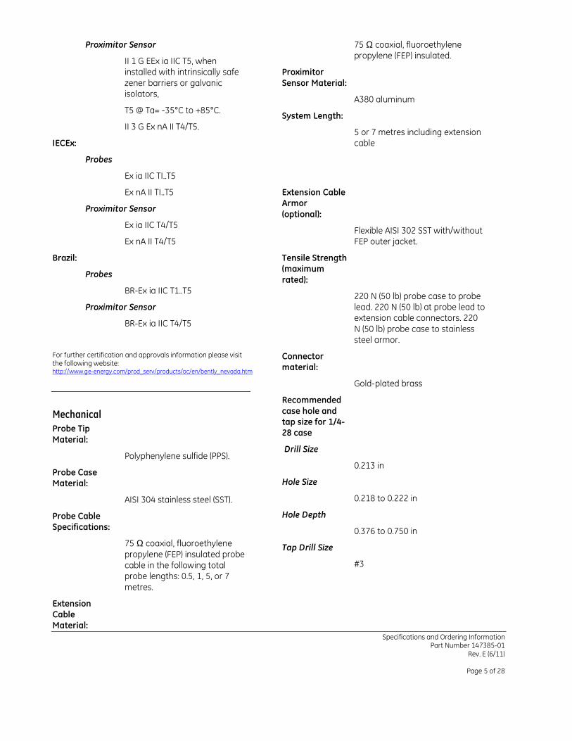
Proximitor Sensor
II 1 G EEx ia IIC T5, when installed with intrinsically safe zener barriers or galvanic isolators,
T5 @ Ta= -35°C to +85°C.
II 3 G Ex nA II T4/T5.
IECEx:
Probes
Ex ia IIC TI..T5
Ex nA II TI..T5
Proximitor Sensor
Ex ia IIC T4/T5
Ex nA II T4/T5
Brazil:
Probes
BR-Ex ia IIC T1..T5
Proximitor Sensor
BR-Ex ia IIC T4/T5
For further certification and approvals information please visit the following website: http://www.ge-energy.com/prod_serv/products/oc/en/bently_nevada.htm
Mechanical
Probe Tip
Material:
Polyphenylene sulfide (PPS).
Probe Case Material:
AISI 304 stainless steel (SST).
Probe Cable Specifications:
75 Ω coaxial, fluoroethylene propylene (FEP) insulated probe cable in the following total probe lengths: 0.5, 1, 5, or 7 metres.
Extension Cable Material:
75 Ω coaxial, fluoroethylene propylene (FEP) insulated.
Proximitor
Sensor Material:
A380 aluminum
System Length:
5 or 7 metres including extension cable
Extension Cable Armor
(optional):
Flexible AISI 302 SST with/without FEP outer jacket.
Tensile Strength (maximum
rated):
220 N (50 lb) probe case to probe lead. 220 N (50 lb) at probe lead to extension cable connectors. 220 N (50 lb) probe case to stainless steel armor.
Connector material:
Gold-plated brass
Recommended
case hole and tap size for 1/4-28 case
Drill Size
0.213 in
Hole Size
0.218 to 0.222 in
Hole Depth
0.376 to 0.750 in
Tap Drill Size
#3
Specifications and Ordering Information Part Number 147385-01
Rev. E (6/11)
Page 6 of 28
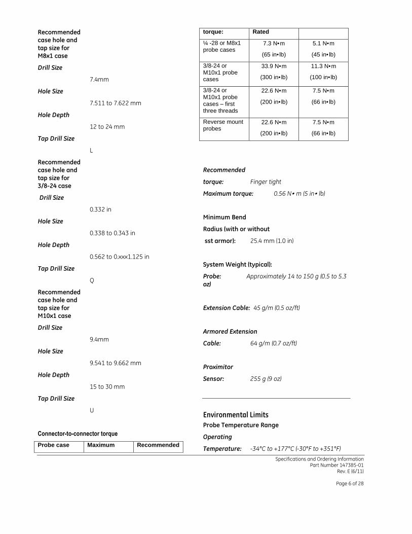
Recommended case hole and
tap size for M8x1 case
Drill Size
7.4mm
Hole Size
7.511 to 7.622 mm
Hole Depth
12 to 24 mm
Tap Drill Size
L
Recommended case hole and
tap size for 3/8-24 case
Drill Size
0.332 in
Hole Size
0.338 to 0.343 in
Hole Depth
0.562 to 0.xxx1.125 in
Tap Drill Size
Q
Recommended case hole and
tap size for M10x1 case
Drill Size
9.4mm
Hole Size
9.541 to 9.662 mm
Hole Depth
15 to 30 mm
Tap Drill Size
U
Connector-to-connector torque
Probe case Maximum Recommended
torque: Rated
¼ -28 or M8x1 probe cases
7.3 N•m
(65 in•lb)
5.1 N•m
(45 in•lb)
3/8-24 or M10x1 probe cases
33.9 N•m
(300 in•lb)
11.3 N•m
(100 in•lb)
3/8-24 or M10x1 probe cases – first three threads
22.6 N•m
(200 in•lb)
7.5 N•m
(66 in•lb)
Reverse mount probes
22.6 N•m
(200 in•lb)
7.5 N•m
(66 in•lb)
Recommended
torque: Finger tight
Maximum torque: 0.56 N• m (5 in• lb)
Minimum Bend
Radius (with or without
sst armor): 25.4 mm (1.0 in)
System Weight (typical):
Probe: Approximately 14 to 150 g (0.5 to 5.3 oz)
Extension Cable: 45 g/m (0.5 oz/ft)
Armored Extension
Cable: 64 g/m (0.7 oz/ft)
Proximitor
Sensor: 255 g (9 oz)
Environmental Limits
Probe Temperature Range
Operating
Temperature: -34°C to +177°C (-30°F to +351°F)
Specifications and Ordering Information Part Number 147385-01
Rev. E (6/11)
Page 7 of 28
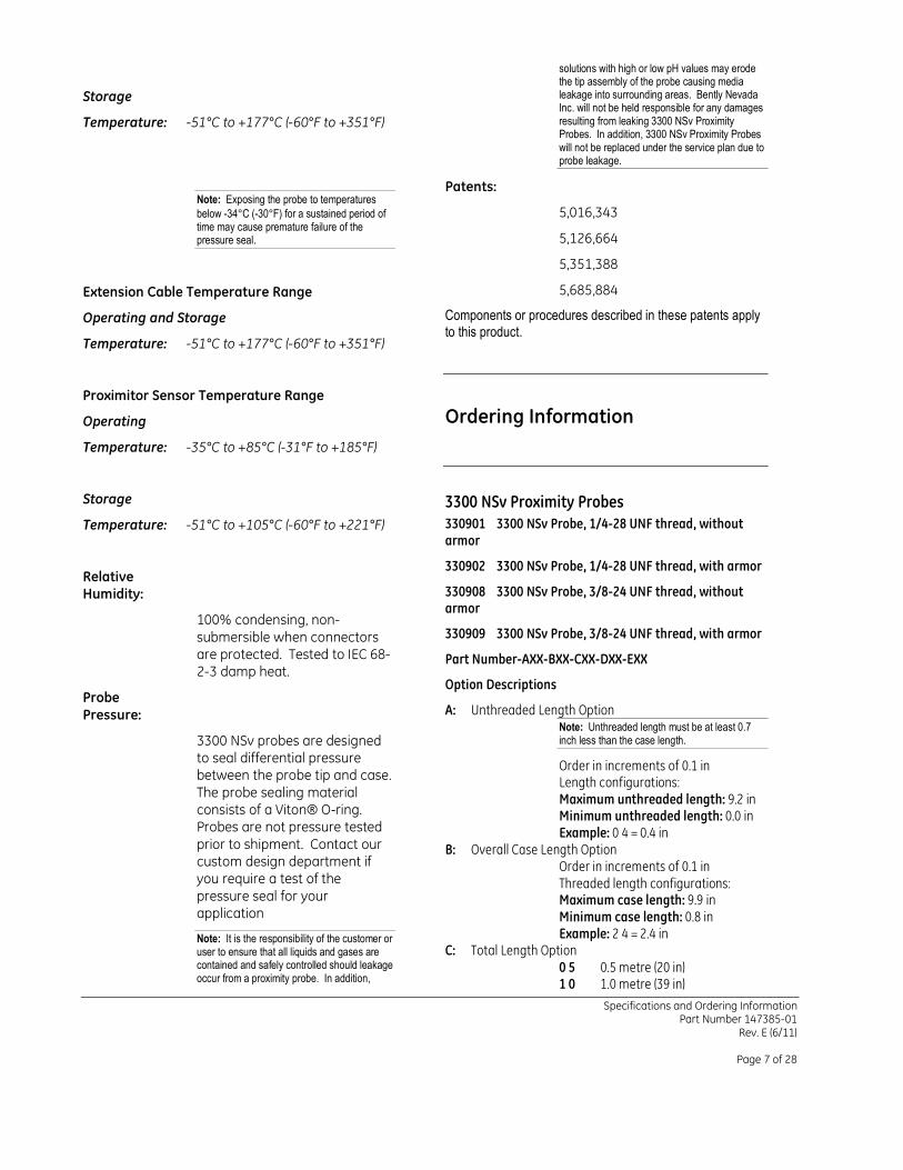
Storage
Temperature: -51°C to +177°C (-60°F to +351°F)
Note: Exposing the probe to temperatures
below -34°C (-30°F) for a sustained period of time may cause premature failure of the pressure seal.
Extension Cable Temperature Range
Operating and Storage
Temperature: -51°C to +177°C (-60°F to +351°F)
Proximitor Sensor Temperature Range
Operating
Temperature: -35°C to +85°C (-31°F to +185°F)
Storage
Temperature: -51°C to +105°C (-60°F to +221°F)
Relative Humidity:
100% condensing, non-submersible when connectors are protected. Tested to IEC 68-2-3 damp heat.
Probe
Pressure:
3300 NSv probes are designed to seal differential pressure between the probe tip and case. The probe sealing material consists of a Viton® O-ring. Probes are not pressure tested prior to shipment. Contact our custom design department if you require a test of the pressure seal for your application
Note: It is the responsibility of the customer or user to ensure that all liquids and gases are contained and safely controlled should leakage occur from a proximity probe. In addition,
solutions with high or low pH values may erode the tip assembly of the probe causing media leakage into surrounding areas. Bently Nevada Inc. will not be held responsible for any damages resulting from leaking 3300 NSv Proximity Probes. In addition, 3300 NSv Proximity Probes will not be replaced under the service plan due to probe leakage.
Patents:
5,016,343
5,126,664
5,351,388
5,685,884
Components or procedures described in these patents apply to this product.
Ordering Information
3300 NSv Proximity Probes
330901 3300 NSv Probe, 1/4-28 UNF thread, without armor
330902 3300 NSv Probe, 1/4-28 UNF thread, with armor
330908 3300 NSv Probe, 3/8-24 UNF thread, without armor
330909 3300 NSv Probe, 3/8-24 UNF thread, with armor
Part Number-AXX-BXX-CXX-DXX-EXX
Option Descriptions
A: Unthreaded Length Option Note: Unthreaded length must be at least 0.7 inch less than the case length.
Order in increments of 0.1 in Length configurations: Maximum unthreaded length: 9.2 in Minimum unthreaded length: 0.0 in Example: 0 4 = 0.4 in
B: Overall Case Length Option Order in increments of 0.1 in Threaded length configurations: Maximum case length: 9.9 in Minimum case length: 0.8 in Example: 2 4 = 2.4 in
C: Total Length Option 0 5 0.5 metre (20 in) 1 0 1.0 metre (39 in)

Specifications and Ordering Information Part Number 147385-01
Rev. E (6/11)
Page 8 of 28
5 0 5.0 metres (16.4 feet) 7 0 7.0 metres (23.0 feet)
D: Connector and Cable-Type Option 0 1 Miniature coaxial ClickLoc
connector with connector protector, standard cable
0 2 Miniature coaxial ClickLoc connector, standard cable
1 1 Miniature coaxial ClickLoc connector with connector protector, FluidLoc cable
1 2 Miniature coaxial ClickLoc connector, FluidLoc cable
E: Agency Approval Option
0 0 Not required 0 5 Multiple Approvals
3300 NSv Proximity Probes, Metric
330903 3300 NSv Probe, M8 x 1 thread, without armor
330904 3300 NSv Probe, M8 x 1 thread, with armor
330905 3300 NSv Probe, M10 x 1 thread, without armor
330910 3300 NSv Probe, M10 x 1 thread, with armor
Part Number-AXX-BXX-CXX-DXX-EXX
Option Descriptions
A: Unthreaded Length Option Note: Unthreaded length must be at least 20 mm less than the case length.
Order in increments of 10 mm. Length configuration: Maximum unthreaded length: 230
mm Minimum unthreaded length: 0 mm Example: 0 6 = 60 mm
B: Overall Case Length Option Order in increments of 10 mm. Metric thread configurations: Maximum length: 250 mm Minimum length: 20 mm Example: 0 6 = 60 mm
C: Total Length Option 0 5 0.5 metre (20 in) 1 0 1.0 metre (39 in) 5 0 5.0 metres (16.4 feet) 7 0 7.0 metres (23.0 feet)
D: Connector and Cable-Type Option
0 1 Miniature coaxial ClickLoc connector with connector protector, standard cable
0 2 Miniature coaxial ClickLoc connector, standard cable
1 1 Miniature coaxial ClickLoc connector with connector protector, FluidLoc cable
1 2 Miniature coaxial ClickLoc connector, FluidLoc cable
E: Agency Approval Option 0 0 Not required 0 5 Multiple Approvals
3300 NSv Reverse Mount Probe
330906-02-12- CXX-DXX-EXX, 3/8-24 UNF threads
330907-05-30- CXX-DXX-EXX, M10 x 1 threads
Option Descriptions
C: Total Length Option 0 5 0.5 metre (20 in) 1 0 1.0 metre (39 in) 5 0 5.0 metres (16.4 feet) 7 0 7.0 metres (23.0 feet)
D: Connector Option 0 2 Miniature coaxial ClickLoc
connector, standard cable 1 2 Miniature coaxial ClickLoc
connector, FluidLoc cable E: Agency Approval Option
0 0 Not required 0 5 Multiple Approvals
Note: For a shorter delivery time, order commonly stocked probes. Currently, stocked probes consist of the following part numbers: 330901-00-24-05-02-00, 330901-00-90-05-02-00, 330902-00-50-05-02-00, 330902-00-95-05-02-00, 330903-00-02-10-02-00, 330903-00-03-10-02-00, 330906-02-12-05-02-00.
3300 XL NSv Proximitor Sensor
330980-AXX-BXX
Option Descriptions
A: Total Length and Mounting Option 5 0 5.0 metre (16.4 feet) system
length, panel mount 5 1 5.0 metre (16.4 feet) system
length, DIN mount

Specifications and Ordering Information Part Number 147385-01
Rev. E (6/11)
Page 9 of 28
5 2 5.0 metre (16.4 feet) system length, no mounting hardware1
7 0 7.0 metres (23.0 feet) system length, panel mount
7 1 7.0 metres (23.0 feet) system length, DIN mount
7 2 7.0 metres (23.0 feet) system length, no mounting hardware1
B: Agency Approval Option 0 0 Not required 0 5 Multiple approvals
3300 NSv Extension Cable
330930-AXXX-BXX-CXX
Note: Make sure that the extension cable length and the probe length, when added together, equal the Proximitor® Sensor total length.
Option Descriptions
A: Cable Length Option 0 4 0 4.0 metres (13.1 feet) 0 4 5 4.5 metres (14.8 feet) 0 6 0 6.0 metres (19.7 feet) 0 6 5 6.5 metres (21.3 feet)
B: Connector and Cable Option 0 0 Without stainless steel
armor 0 1 With stainless steel armor,
with FEP jacket 0 2 With stainless steel armor,
without FEP jacket 0 3 Without stainless steel
armor, with connector protectors
0 4 With stainless steel armor, with FEP jacket, with connector protectors
0 5 With stainless steel armor, without FEP jacket, with connector protectors
0 6 FluidLoc cable without stainless steel armor
0 7 FluidLoc cable with stainless steel armor, with FEP jacket
0 8 FluidLoc cable with stainless steel armor, without FEP jacket
0 9 FluidLoc without stainless steel armor, with connector protectors
1 0 FluidLoc cable with stainless steel armor, with FEP jacket, with connector protectors
1 1 FluidLoc cable with stainless steel armor, without FEP jacket, with connector protectors
C: Agency Approval Option
0 0 Not required 0 5 Multiple Approvals
Accessories
147357-01 Manual
02120015 Bulk field wire. 1.0 mm2 (18 AWG), 3 conductor, twisted, shielded cable with drain wire. Specify length in feet.
138492-01 Replacement panel-mount mounting pad
138493-01 Replacement DIN-mount
mounting pad
01609137 BNC (F) to banana plugs
01609138 Proximitor Connector Test Pin wiring (two test pins to a BNC (F) connector)
40971-04 50 ΩΩΩΩ cable with two BNC (M) connectors. Use this cable in combination with adapter 01609137 and adapter 01609138 when checking performance of the transducer system from the Proximitor Sensor test pin holes.
04310310 3300 XL Proximitor Sensor Panel-
mount Screws. Package includes one 6-32 UNC thread forming mounting screw (Supplied standard with 3300 XL Proximitor Housings [3300 XL option] ).
Specifications and Ordering Information Part Number 147385-01
Rev. E (6/11)
Page 10 of 28
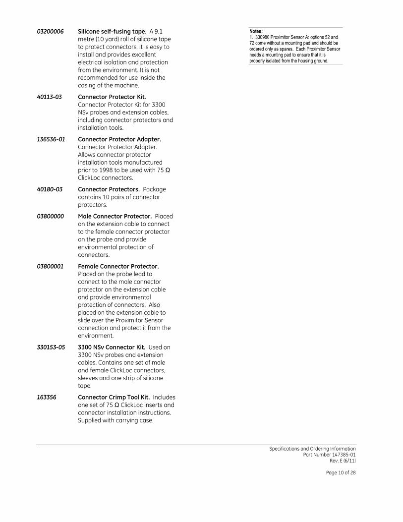
03200006 Silicone self-fusing tape. A 9.1 metre (10 yard) roll of silicone tape to protect connectors. It is easy to install and provides excellent electrical isolation and protection from the environment. It is not recommended for use inside the casing of the machine.
40113-03 Connector Protector Kit. Connector Protector Kit for 3300 NSv probes and extension cables, including connector protectors and installation tools.
136536-01 Connector Protector Adapter. Connector Protector Adapter. Allows connector protector installation tools manufactured prior to 1998 to be used with 75 Ω ClickLoc connectors.
40180-03 Connector Protectors. Package contains 10 pairs of connector protectors.
03800000 Male Connector Protector. Placed on the extension cable to connect to the female connector protector on the probe and provide environmental protection of connectors.
03800001 Female Connector Protector. Placed on the probe lead to connect to the male connector protector on the extension cable and provide environmental protection of connectors. Also placed on the extension cable to slide over the Proximitor Sensor connection and protect it from the environment.
330153-05 3300 NSv Connector Kit. Used on 3300 NSv probes and extension cables. Contains one set of male and female ClickLoc connectors, sleeves and one strip of silicone tape.
163356 Connector Crimp Tool Kit. Includes one set of 75 Ω ClickLoc inserts and connector installation instructions. Supplied with carrying case.
Notes: 1. 330980 Proximitor Sensor A: options 52 and 72 come without a mounting pad and should be ordered only as spares. Each Proximitor Sensor needs a mounting pad to ensure that it is properly isolated from the housing ground.
Specifications and Ordering Information Part Number 147385-01
Rev. E (6/11)
Page 11 of 28
Graphs and Dimensional Drawings
-4
-3
-2
-1
0
1
2
3
4
DS
L E
rro
r (m
ils)
-1.00
-0.75
-0.50
-0.25
0.00
0.25
0.50
0.75
1.00
0.00 0.25 0.50 0.75 1.00 1.25 1.50 1.75 2.00 2.25Gap (mm)
DS
L E
rro
r (m
m)
-15
-10
-5
0
5
10
15
ISF
Err
or
(%)
-24
-22
-20
-18
-16
-14
-12
-10
-8
-6
-4
-2
00 10 20 30 40 50 60 70 80 90Gap (mils)
Ou
tpu
t (V
olt
s)
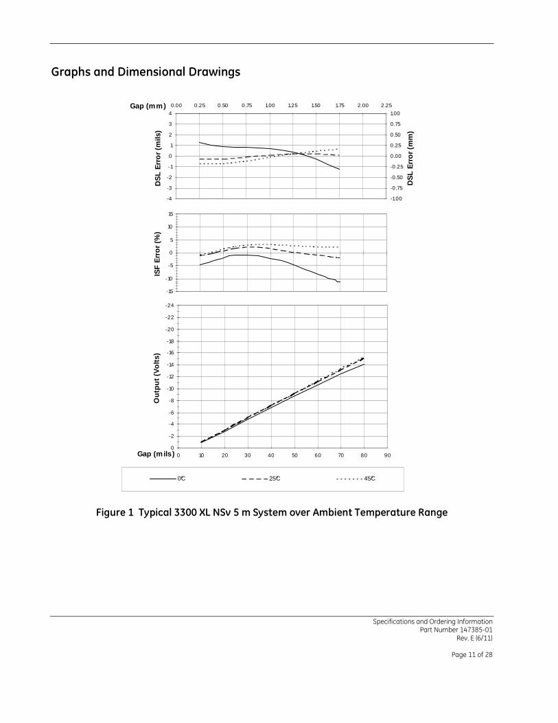
0°C 25°C 45°C
Figure 1 Typical 3300 XL NSv 5 m System over Ambient Temperature Range

Specifications and Ordering Information Part Number 147385-01
Rev. E (6/11)
Page 12 of 28
-4
-3
-2
-1
0
1
2
3
4
DS
L E
rro
r (m
ils)
-1.00
-0.75
-0.50
-0.25
0.00
0.25
0.50
0.75
1.00
0.00 0.25 0.50 0.75 1.00 1.25 1.50 1.75 2.00 2.25Gap (mm)
DS
L E
rro
r (m
m)
-15
-10
-5
0
5
10
15IS
F E
rro
r (%
)
-24
-22
-20
-18
-16
-14
-12
-10
-8
-6
-4
-2
00 10 20 30 40 50 60 70 80 90Gap (mils)
Ou
tpu
t (V
olt
s)
0°C 25°C 45°C
Figure 2 Typical 3300 XL NSv 7 m System over Ambient Temperature Range
Specifications and Ordering Information Part Number 147385-01
Rev. E (6/11)
Page 13 of 28
-4
-3
-2
-1
0
1
2
3
4
DS
L E
rro
r (m
ils)
-0.100
-0.075
-0.050
-0.025
0.000
0.025
0.050
0.075
0.100
0.00 0.25 0.50 0.75 1.00 1.25 1.50 1.75 2.00 2.25Gap (mm)
DS
L E
rro
r (m
m)
-30
-25
-20
-15
-10
-5
0
5IS
F E
rro
r (%
)
-24
-22
-20
-18
-16
-14
-12
-10
-8
-6
-4
-2
00 10 20 30 40 50 60 70 80 90Gap (mils)
Ou
tpu
t (V
olt
s)
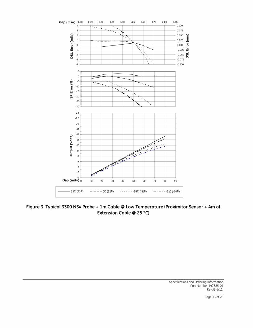
23°C (73°F) 0°C (32°F) -35°C (-31°F) -51°C (-60°F)
Figure 3 Typical 3300 NSv Probe + 1m Cable @ Low Temperature (Proximitor Sensor + 4m of
Extension Cable @ 25 °°°°C)

Specifications and Ordering Information Part Number 147385-01
Rev. E (6/11)
Page 14 of 28
-4
-3
-2
-1
0
1
2
3
4
DS
L E
rro
r (m
ils)
-0.100
-0.075
-0.050
-0.025
0.000
0.025
0.050
0.075
0.100
0.00 0.25 0.50 0.75 1.00 1.25 1.50 1.75 2.00 2.25Gap (mm)
DS
L E
rro
r (m
m)
-15
-10
-5
0
5
10
15IS
F E
rro
r (%
)
-24
-22
-20
-18
-16
-14
-12
-10
-8
-6
-4
-2
00 10 20 30 40 50 60 70 80 90Gap (mils)
Ou
tpu
t (V
olt
s)
23°C (73°F) 65°C (150°F) 121°C (250°F) 177°C (350°F)
Figure 4 Typical 3300 NSv Probe + 1m Cable @ High Temperature (Proximitor Sensor + 4m of
Extension Cable @ 25 °°°°C)
Specifications and Ordering Information Part Number 147385-01
Rev. E (6/11)
Page 15 of 28
-4
-3
-2
-1
0
1
2
3
4
DS
L E
rro
r (m
ils)
-0.100
-0.075
-0.050
-0.025
0.000
0.025
0.050
0.075
0.100
0.00 0.25 0.50 0.75 1.00 1.25 1.50 1.75 2.00 2.25Gap (mm)
DS
L E
rro
r (m
m)
-15
-10
-5
0
5
10
15IS
F E
rro
r (%
)
-24
-22
-20
-18
-16
-14
-12
-10
-8
-6
-4
-2
00 10 20 30 40 50 60 70 80 90Gap (mils)
Ou
tpu
t (V
olt
s)
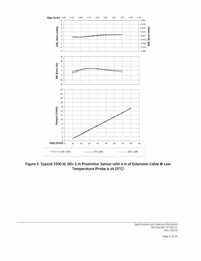
23°C (73°F) 0°C (32°F) -35°C (-31°F)
Figure 5 Typical 3300 XL NSv 5 m Proximitor Sensor with 4 m of Extension Cable @ Low
Temperature (Probe is at 25°°°°C)

Specifications and Ordering Information Part Number 147385-01
Rev. E (6/11)
Page 16 of 28
-4
-3
-2
-1
0
1
2
3
4
DS
L E
rro
r (m
ils)
-0.100
-0.075
-0.050
-0.025
0.000
0.025
0.050
0.075
0.100
0.00 0.25 0.50 0.75 1.00 1.25 1.50 1.75 2.00 2.25Gap (mm)
DS
L E
rro
r (m
m)
-15
-10
-5
0
5
10
15IS
F E
rro
r (%
)
-24
-22
-20
-18
-16
-14
-12
-10
-8
-6
-4
-2
00 10 20 30 40 50 60 70 80 90Gap (mils)
Ou
tpu
t (V
olt
s)
23°C (73°F) 45°C (113°F) 65°C (150°F) 85°C (185°F)
Figure 6 Typical 3300 XL NSv 5 m Proximitor Sensor with 4 m Extension Cable @ High
Temperature (Probe is at 25°°°°C)
Specifications and Ordering Information Part Number 147385-01
Rev. E (6/11)
Page 17 of 28
-4
-3
-2
-1
0
1
2
3
4
DS
L E
rro
r (m
ils)
-0.100
-0.075
-0.050
-0.025
0.000
0.025
0.050
0.075
0.100
0.00 0.25 0.50 0.75 1.00 1.25 1.50 1.75 2.00 2.25Gap (mm)
DS
L E
rro
r (m
m)
-15
-10
-5
0
5
10
15IS
F E
rro
r (%
)
-24
-22
-20
-18
-16
-14
-12
-10
-8
-6
-4
-2
00 10 20 30 40 50 60 70 80 90Gap (mils)
Ou
tpu
t (V
olt
s)
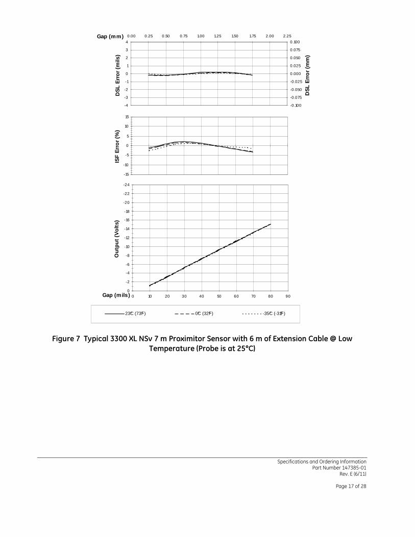
23°C (73°F) 0°C (32°F) -35°C (-31°F)
Figure 7 Typical 3300 XL NSv 7 m Proximitor Sensor with 6 m of Extension Cable @ Low
Temperature (Probe is at 25°°°°C)
Specifications and Ordering Information Part Number 147385-01
Rev. E (6/11)
Page 18 of 28
-4
-3
-2
-1
0
1
2
3
4
DS
L E
rro
r (m
ils)
-0.100
-0.075
-0.050
-0.025
0.000
0.025
0.050
0.075
0.100
0.00 0.25 0.50 0.75 1.00 1.25 1.50 1.75 2.00 2.25Gap (mm)
DS
L E
rro
r (m
m)
-15
-10
-5
0
5
10
15IS
F E
rro
r (%
)
-24
-22
-20
-18
-16
-14
-12
-10
-8
-6
-4
-2
00 10 20 30 40 50 60 70 80 90Gap (mils)
Ou
tpu
t (V
olt
s)
23°C (73°F) 45°C (113°F) 65°C (150°F) 85°C (185°F)
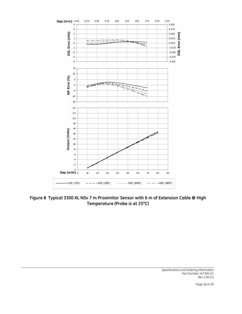
Figure 8 Typical 3300 XL NSv 7 m Proximitor Sensor with 6 m of Extension Cable @ High
Temperature (Probe is at 25°°°°C)

Specifications and Ordering Information Part Number 147385-01
Rev. E (6/11)
Page 19 of 28
-6
-4
-2
0
2
4
6
DS
L E
rro
r (m
ils)
-0.15
-0.10
-0.05
0.00
0.05
0.10
0.15
0.00 0.25 0.50 0.75 1.00 1.25 1.50 1.75 2.00 2.25Gap (mm)
DS
L E
rro
r (m
m)
-30
-25
-20
-15
-10
-5
0
5IS
F E
rro
r (%
)
-24
-22
-20
-18
-16
-14
-12
-10
-8
-6
-4
-2
00 10 20 30 40 50 60 70 80 90Gap (mils)
Ou
tpu
t (V
olt
s)
No CB 10.2 mm (0.400 in) 9.5 mm (0.375 in) 8.9 mm (0.350 in)
Figure 9 Effect of Counterbore Side Clearance (4140 Material)

Specifications and Ordering Information Part Number 147385-01
Rev. E (6/11)
Page 20 of 28
-4
-3
-2
-1
0
1
2
3
4
DS
L E
rro
r (m
ils)
-0.100
-0.075
-0.050
-0.025
0.000
0.025
0.050
0.075
0.100
0.00 0.25 0.50 0.75 1.00 1.25 1.50 1.75 2.00 2.25Gap (mm)
DS
L E
rro
r (m
m)
-15
-10
-5
0
5
10
15IS
F E
rro
r (%
)
-24
-22
-20
-18
-16
-14
-12
-10
-8
-6
-4
-2
00 10 20 30 40 50 60 70 80 90Gap (mils)
Ou
tpu
t (V
olt
s)
NO M ETAL NEAR PROBE10.2 mm (0.400 in) Probe Center to M etal Edge7.6 mm (0.300 in) Probe Center to M etal Edge5.1 mm (0.200 in) Probe Center to M etal Edge3.2 mm (0.125 in) Probe Center to M etal Edge
Figure 10 Effect of Flat Surface Side Clearance (4140 Material)

Specifications and Ordering Information Part Number 147385-01
Rev. E (6/11)
Page 21 of 28
-6
-4
-2
0
2
4
6
DS
L E
rro
r (m
ils)
-0.15
-0.10
-0.05
0.00
0.05
0.10
0.15
0.00 0.25 0.50 0.75 1.00 1.25 1.50 1.75 2.00 2.25Gap (mm)
DS
L E
rro
r (m
m)
-30
-25
-20
-15
-10
-5
0
5IS
F E
rro
r (%
)
-24
-22
-20
-18
-16
-14
-12
-10
-8
-6
-4
-2
00 10 20 30 40 50 60 70 80 90Gap (mils)
Ou
tpu
t (V
olt
s)
NO M ETAL NEAR PROBE 5.1 mm (0.200 in) Tip to M etal
3.8 mm (0.150 in) Tip to M etal 2.5 mm (0.100 in) Tip to M etal
Figure 11 Effect of Rear Surface Clearance (4140 Material)

Specifications and Ordering Information Part Number 147385-01
Rev. E (6/11)
Page 22 of 28
7.67
7.87
8.07
8.27
0.30.40.50.60.70.80.911.11.2
Shaft Diameter (inches)
AS
F (
V/m
m)
195
200
205
210
7.610.212.715.217.820.322.925.427.930.5
Shaft Diameter (mm)
AS
F (
mV
/mil)
Figure 12 Axial Sensitivity to Shaft Size
7.67
7.87
8.07
8.27
8.47
8.67
0 1 2 3 4
Shaft Diameter (inches)
AS
F (
V/m
m)
195
200
205
210
215
220
0 25.4 50.8 76.2 101.6Shaft Diameter (mm)
AS
F (
mV
/mil)
Figure 13 Radial Sensitivity to Shaft Size

Specifications and Ordering Information Part Number 147385-01
Rev. E (6/11)
Page 23 of 28
0.0
80.0
160.0
240.0
320.0
400.0
480.0
560.0
0.6 0.7 0.8 0.9 1.0 1.1 1.2Center to Center Probe Separation (Inches)
Pro
xim
ito
r O
utp
ut
Vo
ltag
e (m
Vp
p) 15.2 17.8 20.3 22.9 25.4 27.9 30.5
Center to Center Probe Separation (mm)
Figure 14 Probe Cross-talk with Probes Mounted in Parallel
0.0
20.0
40.0
60.0
80.0
100.0
120.0
140.0
160.0
180.0
200.0
220.0
0.8 1.0 1.2 1.4
Shaft Diameter (inches)
Pro
xim
ito
r O
utp
ut
Vo
ltag
e (m
Vp
p) 20.3 25.4 30.5 35.6
Shaft Diameter (mm)
Figure 15 Probe Cross-talk with Probes Mounted in X-Y Configuration

Specifications and Ordering Information Part Number 147385-01
Rev. E (6/11)
Page 24 of 28
-6
-5
-4
-3
-2
-1
0
1
100 1000 10000 100000
Frequency (Hz)
0 m (0 ft) 300 m (1000 ft) 600 m (2000 ft) 1500 m (5000 ft) 3600 m (12000 ft)
Figure 16 Frequency Response, magnitude of typical 3300 XL NSv System with various lengths of field wiring, no barriers
-100
-80
-60
-40
-20
0
20
100 1000 10000 100000
Frequency (Hz)
Ph
ase
Lag
(d
eg)
0 m (0 ft) 300 m (1000 ft) 600 m (2000 ft) 1500 m (5000 ft) 3600 m (12000 ft)
Figure 17 Frequency Response, phase change of typical 3300 XL NSv System with various lengths of field wiring, no barriers
Specifications and Ordering Information Part Number 147385-01
Rev. E (6/11)
Page 25 of 28
Hex Nut Wrench Flats
(0.207)
2.92 (0.115) Max.
Case Length "B"
5.26
Probe Tip
Total Length "C", +30%, -0%
ThreadCase
2.8 (0.11) Max. Outside Dia.75 ohm Cable
Coaxial ConnectorMiniature Male
7.23 (0.285) OutsideDia. Maximum "D"
7.6 (0.30) Max. Outside Dia. of Armor
Unthreaded Length"A"
3.23 (0.127)
Dia. Max.
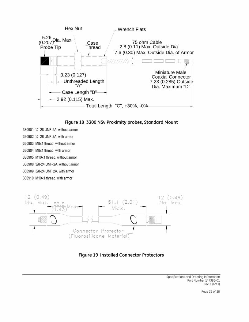
Figure 18 3300 NSv Proximity probes, Standard Mount
330901, ¼ -28 UNF-2A, without armor
330902, ¼ -28 UNF-2A, with armor
330903, M8x1 thread, without armor
330904, M8x1 thread, with armor
330905, M10x1 thread, without armor
330908, 3/8-24 UNF-2A, without armor
330909, 3/8-24 UNF 2A, with armor
330910, M10x1 thread, with armor
Figure 19 Installed Connector Protectors

Specifications and Ordering Information Part Number 147385-01
Rev. E (6/11)
Page 26 of 28
(0.207)
2.92 (0.115) Max.
Case Length "B"
5.26
Probe Tip
Unthreaded Length "A"
Total Length "C", +30%, -0%
7/16 or 10mmHex
ThreadCase
2.8 (0.11) outside Dia.75 ohm Cable
Coaxial ConnectorMiniature Male
7.23 (0.285) OutsideDia. Maximum "D"
Dia. Max.
5.08 (0.20)
30.48 (1.20)
5.08 (0.20)
Figure 20 3300 NSv Proximity Probes, Reverse Mount
330906, 3/8-24 UNF-2A threads
330907, M10x1 threads
Max. Dia.Uncoated ArmorFEP Coated or
Coaxial ConnectorMiniature Female
Coaxial CableFEP Insulated
8.4 (0.33) Dia.Stainless Steel Ferrules
Cable Length +20%, -0%
7.2 (0.285)
300 (11.8)Armor Length:(2.0)
51
Coaxial ConnectorMiniature Male
Max. Dia.7.2 (0.285)
less than cable length
(2.0)51
(3.25)82.682.6
(3.25)
2.80 (0.11) max. O.D.7.6 (0.30) Max. O.D. of Armor
75 ohm cable
7.0 (0.275) Max. O.D. of Uncoated Armor
Figure 21 330930, 3300 NSv Extension Cable
Specifications and Ordering Information Part Number 147385-01
Rev. E (6/11)
Page 27 of 28
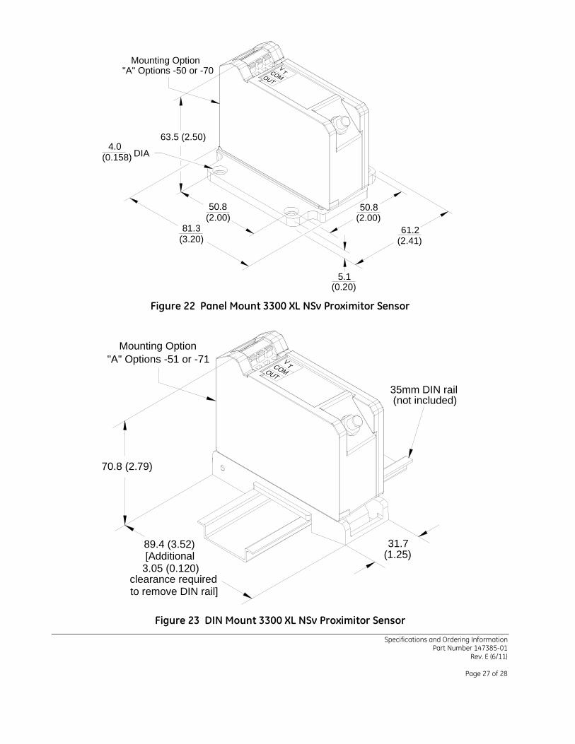
Mounting Option"A" Options -50 or -70
63.5 (2.50)
50.8(2.00)
81.3(3.20)
50.8(2.00)
61.2(2.41)
5.1(0.20)
(0.158)4.0
DIA
Figure 22 Panel Mount 3300 XL NSv Proximitor Sensor
70.8 (2.79)
89.4 (3.52) 31.7(1.25)[Additional
3.05 (0.120)clearance requiredto remove DIN rail]
Mounting Option"A" Options -51 or -71
35mm DIN rail(not included)
Figure 23 DIN Mount 3300 XL NSv Proximitor Sensor

Specifications and Ordering Information Part Number 147385-01
Rev. E (6/11)
Page 28 of 28
Notes:
All dimensions on figures are in millimeters (inches) unless otherwise noted.
Standard mount ¼ -28 UNF thread probes are supplied with 7⁄16 inch lock nut and 7⁄32 wrench flats.
Standard mount M8x1 thread probes are supplied with 13 mm lock nut and 7 mm wrench flats.
Standard mount 3⁄8-24 UNF thread probes are supplied with 9⁄16 inch lock nut and 5⁄16 wrench flats.
Standard mount M10x1 thread probes are supplied with 17 mm lock nut and 8 mm wrench flats.
Reverse mount probes are not available with armor or connector protector options.
Letters inside quotation marks on figures refer to probe ordering options.
Stainless steel armor is supplied with or without FEP outer jacket.
FEP jacket is standard on all non-armored probes.
* Denotes a trademark of Bently Nevada, Inc., a wholly owned subsidiary of General Electric Company. Viton® is a trademark of DuPont.
© 2001 – 2011 Bently Nevada, Inc. All rights reserved.
Printed in USA. Uncontrolled when transmitted electronically.
1631 Bently Parkway South, Minden, Nevada USA 89423
Phone: 775.782.3611 Fax: 775.215.2873 www.ge-mcs.com/bently


