
3/2, 5/2, 5/2 bistable and 5/3 way pneumatic solenoid valve
37
p. 1/37 www.burkert.com 6518/6519 3/2, 5/2, 5/2 bistable and 5/3 way pneumatic solenoid valve Type 2508 Cable plug Type 2510/11 Cable plug ASI Type 6518/6519 can be combined with... Type 2012 Single seat valve Type 2030 Diaphragm valve • Single or block mounting • Suitable for outdoor and chemical atmospheres • Suitable for low temperatures • Explosion-proof versions • Threaded or NAMUR flange connections Type 6518 Type 6519 Content 6518/6519 Page 6518/6519 Standard temperature range 6518/6519 Standard 2 Ex m 3 Ex i 4 6519 NAMUR Standard 5 Ex m 6 Ex i 7 Manifold assembly with MP07 pneumatic modules 8 Accessories 10 Dimensions 12 6519 with extended temperature range 6519 Standard 20 Ex m 22 Ex i 24 6519 NAMUR Standard 26 Ex m 28 Ex i 30 Accessories 32 Dimensions 34 Type 2513 Cable plug (ATEX Cat. 3 GD) The Type 6518 is a servo-assisted 3/2 way valve and the Type 6519 is a 5/2 or 5/3 way valve. Together, they form a product line. The valves can be used individually or in blocks. The valves work without a continuous air consump- tion and are used for the pneumatic control of double or single-acting actuators. A solenoid valve Type 6014 is used as a pilot. The use of high quality materials makes it possible to use these valves in the open air and under chemi- cal atmospheres. The product line contains units with Ex-Approvals and NAMUR flange interface.
Transcript of 3/2, 5/2, 5/2 bistable and 5/3 way pneumatic solenoid valve

p. 1/37www.burkert.com
6518/6519
3/2, 5/2, 5/2 bistable and 5/3 way pneumatic solenoid valve
Type 2508
Cable plug
Type 2510/11
Cable plug ASI
Type 6518/6519 can be combined with...
Type 2012
Single seat valve
Type 2030
Diaphragm valve
•Singleorblockmounting
•Suitableforoutdoorandchemicalatmospheres
•Suitableforlowtemperatures
•Explosion-proofversions
•ThreadedorNAMURflangeconnections
Type6518
Type6519
Content 6518/6519 Page
6518/6519 Standard temperature range
6518/6519 Standard 2
Exm 3
Exi 4
6519 NAMUR Standard 5
Exm 6
Exi 7
Manifold assembly with MP07 pneumatic modules 8
Accessories 10
Dimensions 12
6519 with extended temperature range
6519 Standard 20
Exm 22
Exi 24
6519 NAMUR Standard 26
Exm 28
Exi 30
Accessories 32
Dimensions 34
Type 2513
Cable plug (ATEX Cat. 3 GD)
The Type 6518 is a servo-assisted 3/2 way valve and the Type 6519 is a 5/2 or 5/3 way valve. Together, they form a product line. The valves can be used individually or in blocks. The valves work without a continuous air consump-tion and are used for the pneumatic control of double or single-acting actuators. A solenoid valve Type 6014 is used as a pilot. The use of high quality materials makes it possible to use these valves in the open air and under chemi-cal atmospheres. The product line contains units with Ex-Approvals and NAMUR flange interface.
6518/6519
p. 2/37
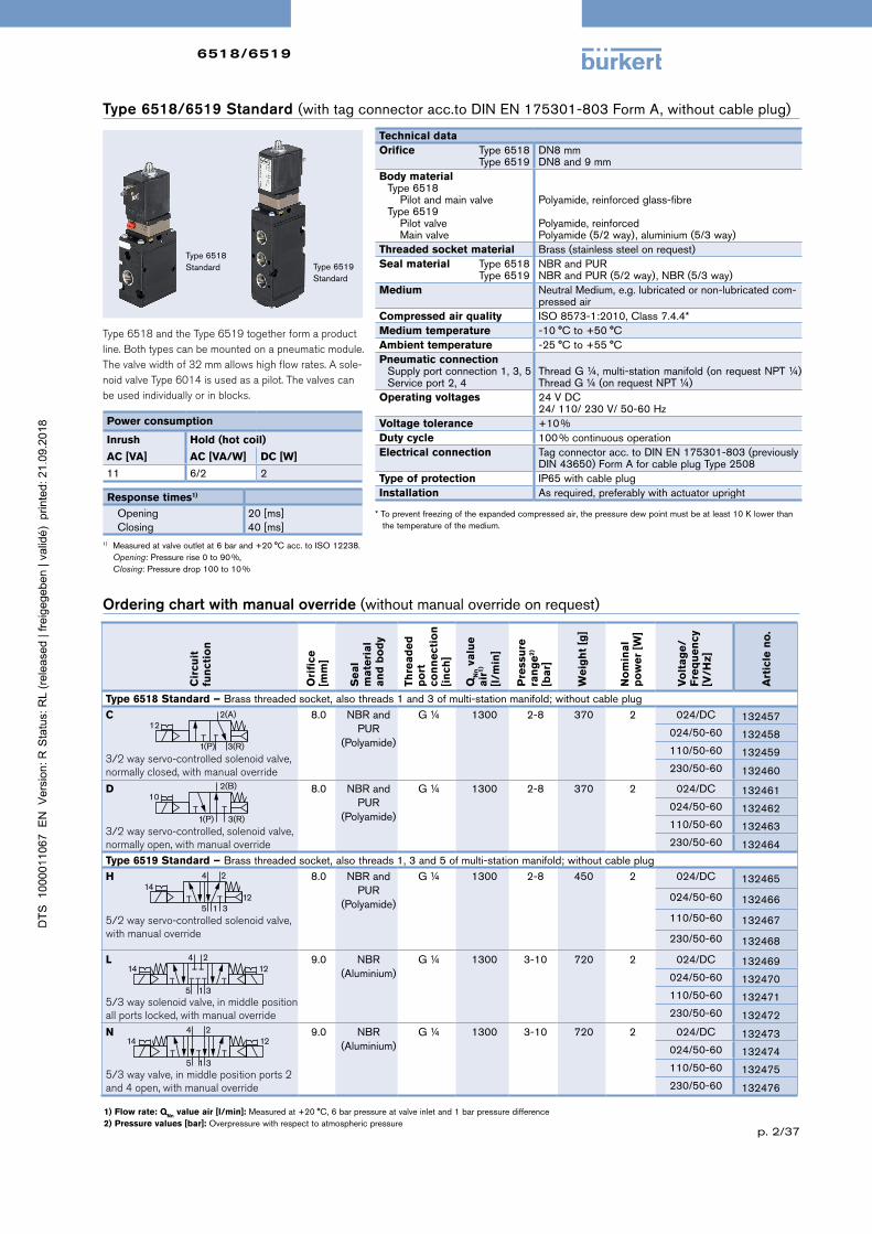
Type 6518/6519 Standard (withtagconnectoracc.toDINEN175301-803FormA,withoutcableplug)
1) Flow rate: QNn value air [l/min]:Measuredat+20°C,6barpressureatvalveinletand1barpressuredifference2) Pressure values [bar]:Overpressurewithrespecttoatmosphericpressure
Ordering chart with manual override (withoutmanualoverrideonrequest)
Cir
cuit
fu
nct
ion
Ori
fice
[m
m]
Se
al
m
ate
ria
l a
nd
bo
dy
Thre
ad
ed
p
ort
co
nn
ect
ion
[i
nch
]
QN
n v
alu
e
air
1)
[l/m
in]
Pre
ssu
re
ran
ge
2)
[ba
r]
We
igh
t [g
]
No
min
al
po
we
r [W
]
Vo
lta
ge
/F
req
ue
ncy
[V
/Hz]
Art
icle
no
.
Type 6518 Standard – Brassthreadedsocket, also threads1and3ofmulti-stationmanifold;withoutcableplugC
3/2 way servo-controlled solenoid valve,normally closed, with manual override
8.0 NBRandPUR
(Polyamide)
G¼ 1300 2-8 370 2 024/DC 132457024/50-60 132458110/50-60 132459230/50-60 132460
D
3/2 way servo-controlled, solenoid valve,normally open, with manual override
8.0 NBRandPUR
(Polyamide)
G¼ 1300 2-8 370 2 024/DC 132461024/50-60 132462110/50-60 132463230/50-60 132464
Type 6519 Standard – Brassthreadedsocket, also threads1,3and5ofmulti-stationmanifold;withoutcableplugH
5/2 way servo-controlled solenoid valve,with manual override
8.0 NBRandPUR
(Polyamide)
G¼ 1300 2-8 450 2 024/DC 132465
024/50-60 132466
110/50-60 132467
230/50-60 132468
L
5/3 way solenoid valve, in middle position all ports locked, with manual override
9.0 NBR(Aluminium)
G¼ 1300 3-10 720 2 024/DC 132469024/50-60 132470110/50-60 132471230/50-60 132472
N
5/3 way valve, in middle position ports 2 and 4 open, with manual override
9.0 NBR(Aluminium)
G¼ 1300 3-10 720 2 024/DC 132473024/50-60 132474110/50-60 132475230/50-60 132476
2(A)
1(P) 3(R)
12
2(B)
1(P) 3(R)
10
14 124 2
5 1 3
14 124 2
5 1 3
1) Measuredatvalveoutletat6barand+20°Cacc.toISO12238. Opening:Pressurerise0to90%, Closing:Pressuredrop100to10%
Type6518Standard Type6519
Standard
Type 6518 and the Type 6519 together form a product line. Both types can be mounted on a pneumatic module. The valve width of 32 mm allows high flow rates. A sole-noid valve Type 6014 is used as a pilot. The valves can be used individually or in blocks.
Power consumption
Inrush Hold (hot coil)
AC [VA] AC [VA/W] DC [W]
11 6/2 2
Response times1)
Opening Closing
20[ms]40[ms]
1412
4 2
5 1 3
Technical dataOrifice Type6518
Type6519DN8mmDN8and9mm
Body materialType6518 PilotandmainvalveType6519 Pilotvalve Mainvalve
Polyamide,reinforcedglass-fibrePolyamide,reinforcedPolyamide(5/2way),aluminium(5/3way)
Threaded socket material Brass(stainlesssteelonrequest)Seal material Type6518
Type6519NBRandPURNBRandPUR(5/2way),NBR(5/3way)
Medium NeutralMedium,e.g.lubricatedornon-lubricatedcom-pressedair
Compressed air quality ISO8573-1:2010,Class7.4.4*Medium temperature -10°Cto+50°CAmbient temperature -25°Cto+55°CPneumatic connection
Supplyportconnection1,3,5Serviceport2,4
ThreadG¼,multi-stationmanifold(onrequestNPT¼)ThreadG¼(onrequestNPT¼)
Operating voltages 24VDC24/110/230V/50-60Hz
Voltage tolerance +10%Duty cycle 100%continuousoperationElectrical connection Tagconnectoracc.toDINEN175301-803(previously
DIN43650)FormAforcableplugType2508Type of protection IP65withcableplugInstallation Asrequired,preferablywithactuatorupright
*Topreventfreezingoftheexpandedcompressedair,thepressuredewpointmustbeatleast10Klowerthan thetemperatureofthemedium.
6518/6519
p. 3/37
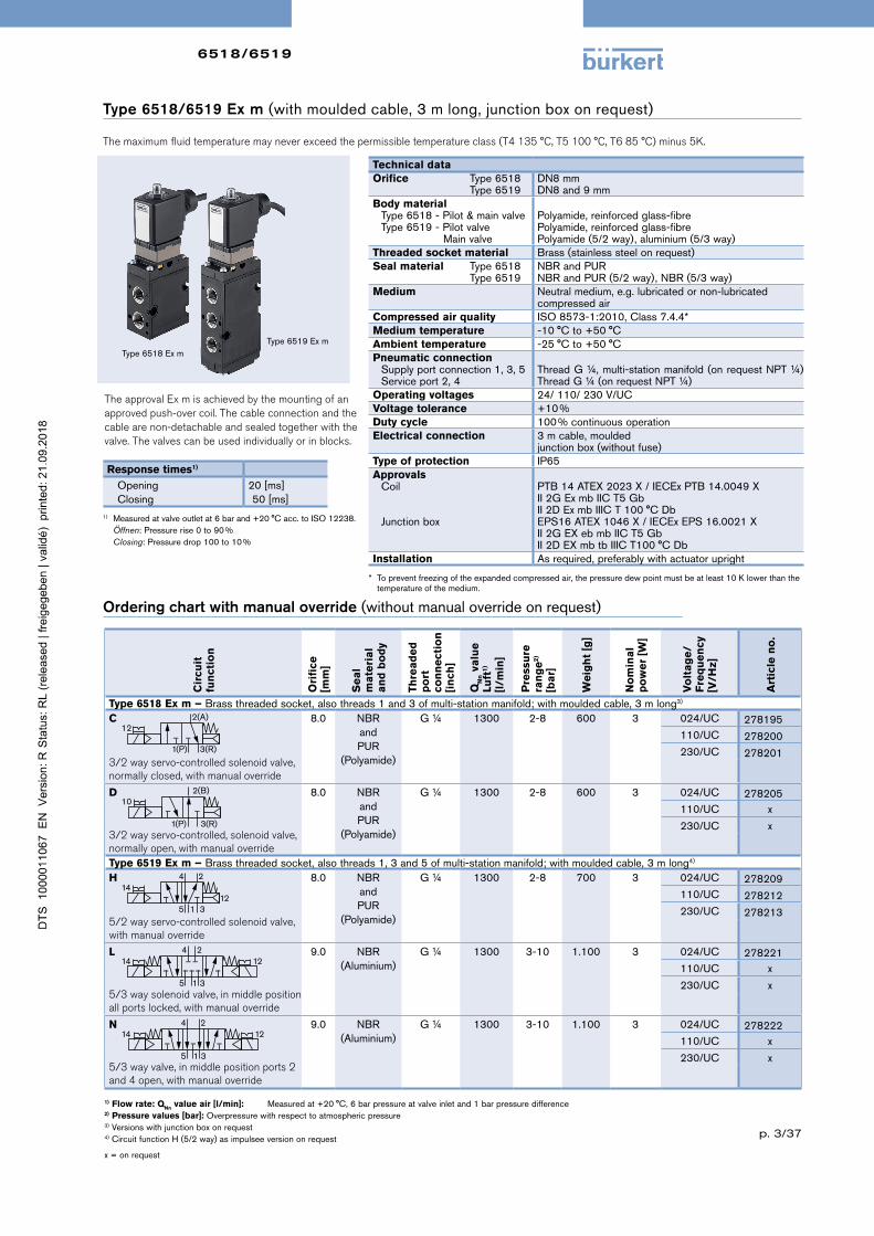
Type 6518/6519 Ex m (withmouldedcable,3mlong,junctionboxonrequest)
The maximum fluid temperature may never exceed the permissible temperature class (T4 135 °C, T5 100 °C, T6 85 °C) minus 5K.
Cir
cuit
fu
nct
ion
Ori
fice
[m
m]
Se
al
ma
teri
al
an
d b
od
y
Thre
ad
ed
p
ort
co
nn
ect
ion
[i
nch
]
QN
n v
alu
e
Luft
1)
[l/m
in]
Pre
ssu
re
ran
ge
2)
[ba
r]
We
igh
t [g
]
No
min
al
po
we
r [W
]
Vo
lta
ge
/F
req
ue
ncy
[V
/Hz]
Art
icle
no
.
Type 6518 Ex m – Brassthreadedsocket, alsothreads1and3ofmulti-stationmanifold;withmouldedcable,3mlong3)
C
3/2 way servo-controlled solenoid valve,normally closed, with manual override
8.0 NBRandPUR
(Polyamide)
G¼ 1300 2-8 600 3 024/UC 278195110/UC 278200230/UC 278201
D
3/2 way servo-controlled, solenoid valve,normally open, with manual override
8.0 NBRandPUR
(Polyamide)
G¼ 1300 2-8 600 3 024/UC 278205110/UC x
230/UC x
Type 6519 Ex m – Brassthreadedsocket, alsothreads1,3and5ofmulti-stationmanifold;withmouldedcable,3mlong4)
H
5/2 way servo-controlled solenoid valve,with manual override
8.0 NBRandPUR
(Polyamide)
G¼ 1300 2-8 700 3 024/UC 278209110/UC 278212230/UC 278213
L
5/3 way solenoid valve, in middle position all ports locked, with manual override
9.0 NBR(Aluminium)
G¼ 1300 3-10 1.100 3 024/UC 278221110/UC x
230/UC x
N
5/3 way valve, in middle position ports 2 and 4 open, with manual override
9.0 NBR(Aluminium)
G¼ 1300 3-10 1.100 3 024/UC 278222110/UC x
230/UC x
1) Flow rate: QNn value air [l/min]: Measuredat+20°C,6barpressureatvalveinletand1barpressuredifference2) Pressure values [bar]:Overpressurewithrespecttoatmosphericpressure3)Versionswithjunctionboxonrequest4)CircuitfunctionH(5/2way)asimpulseeversiononrequest
x=onrequest
Ordering chart with manual override (withoutmanualoverrideonrequest)
1) Measuredatvalveoutletat6barand+20°Cacc.toISO12238. Öffnen:Pressurerise0to90% Closing:Pressuredrop100to10%
Type6519Exm
The approval Ex m is achieved by the mounting of an approved push-over coil. The cable connection and the cable are non-detachable and sealed together with the valve. The valves can be used individually or in blocks.
Response times1)
Opening Closing
20[ms]50[ms]
Type6518Exm
Technical dataOrifice Type6518
Type6519DN8mmDN8and9mm
Body materialType6518-Pilot&mainvalveType6519-Pilotvalve Mainvalve
Polyamide,reinforcedglass-fibrePolyamide,reinforcedglass-fibrePolyamide(5/2way),aluminium(5/3way)
Threaded socket material Brass(stainlesssteelonrequest)Seal material Type6518
Type6519NBRandPURNBRandPUR(5/2way),NBR(5/3way)
Medium Neutralmedium,e.g.lubricatedornon-lubricatedcompressedair
Compressed air quality ISO8573-1:2010,Class7.4.4*Medium temperature -10°Cto+50°CAmbient temperature -25°Cto+50°CPneumatic connection
Supplyportconnection1,3,5Serviceport2,4
ThreadG¼,multi-stationmanifold(onrequestNPT¼)ThreadG¼(onrequestNPT¼)
Operating voltages 24/110/230V/UCVoltage tolerance +10%Duty cycle 100%continuousoperationElectrical connection 3mcable,moulded
junctionbox(withoutfuse)Type of protection IP65Approvals
Coil
Junctionbox
PTB14ATEX2023X/IECExPTB14.0049XII2GExmbIICT5GbII2DExmbIIICT100°CDbEPS16ATEX1046X/IECExEPS16.0021XII2GEXebmbIICT5GbII2DEXmbtbIIICT100°CDb
Installation Asrequired,preferablywithactuatorupright
* Topreventfreezingoftheexpandedcompressedair,thepressuredewpointmustbeatleast10Klowerthanthetemperatureofthemedium.
2(A)
1(P) 3(R)
12
2(B)
1(P) 3(R)
10
14 124 2
5 1 3
14 124 2
5 1 3
1412
4 2
5 1 3

6518/6519
p. 4/37
Type 6518/6519 Ex i(withTagconnectoracc.toDINEN175301-803FormA,withoutcableplug)
The maximum fluid temperature may never exceed the permissible temperature class (T4 135 °C, T5 100 °C, T6 85 °C) minus 5K.
Cir
cuit
fu
nct
ion
Ori
fice
[m
m]
Se
al
ma
-te
ria
l a
nd
b
od
y
Thre
ad
ed
p
ort
co
nn
ect
ion
[i
nch
]
QN
n v
alu
e
Luft
1)
[l/m
in]
Pre
ssu
re
ran
ge
2) [b
ar]
We
igh
t [g
]
Bo
dy
ma
teri
al
pil
ot
valv
e
Ma
teri
al
air
co
ntr
ol
con
ne
cto
r
Art
icle
no
.
Type 6518 Ex i without cable plugC
3/2 way servo-controlled solenoid valve, normally closed
8.0
NBRandPUR
(Polyamide)
G¼ 1300 2-8 580
St.St.1.4305
St.St. 145111Brass,nickel
plated 144486
BrassBrass,nickel
plated 147253
Type 6519 Ex i without cable plug
H
5/2wayservo-controlledsolenoidvalve
8.0
NBRandPUR
(Polyamide)
G¼ 1300 2-8 670
St.St.1.4305
St.St.144484
Brass,nickelplated 144485
BrassBrass,nickel
plated 147252
1) Flow rate: QNn value air [l/min]:Measuredat+20°C,6barpressureatvalveinletand1barpressuredifference2) Pressure values [bar]:Overpressurewithrespecttoatmosphericpressure
Ordering chart for valves without manual override (withmanualoverrideandhighresistancecoilonrequest)
NoteThese units may only be used in explosive atmospheres in the manner approved by the Federal Institute of Physics and Technology (PTB), i.e., the permissible maximum electrical values must be complied with. Suitable barriers and isolating modules are available for this.
Electrical data - Coil AC10 Ex iApprovals PTB01ATEX2101/PTBIECEx10.0019
II2GExiaIICT6GbII2GExiaIIICT80°CDb
Function values forSwitching function valve1) at +20 °C at +55 °C Minimumswitchingcurrent Nominalresistancecoil Minimumterminalvoltage
29mA310Ω9.0V
29mA360Ω10.4V
Conformity specifications Ui Ii Pi
35V0.9A1.1W
Type6518Exi Type6519
Exi
The intrinsically-safe Type 6518 Ex i and 6519 Ex i valves consist of an intrinsically-safe pilot control and a pneumatic amplifier. The diaphragm-controlled valve seats work with very low friction, ensuring reliable switching of the valve, even after long shutdown periods.
1) Measuredatvalveoutletat6barand+20°Cacc.toISO12238. Opening:Pressurerise0to90% Closing:Pressuredrop100to10%
The valve is intended for operation on 24 V DC outputs via the intermediate switching of a corresponding intrinsically-safe operating resource (isolating module or barrier). If required, request the “Recommended Barrier and Isolating Module” data sheet.
1)Withhighresistancecoilonrequest
Response times1)
Opening Closing
75[ms]115[ms]
Technical dataOrifice Type6518
Type6519DN8mmDN8and9mm
Body materialPilotvalveMainvalve
Stainlesssteel1.4305orbrassPolyamide,reinforcedglass-fibre
Threaded socket material Brass(stainlesssteelonrequest)Seal material FPM,NBRandPURMedium Neutralmedium,e.g.lubricatedornon-lubricated
compressedairCompressed air quality ISO8573-1:2010,Class7.4.4*Medium temperature -10°Cto+50°CAmbient temperature -25°Cto+55°CPneumatic connection
Supplyportconnection1,3,5Serviceport2,4
ThreadG¼,multi-stationmanifold(onrequestPT1/4)ThreadG¼(onrequestNPT¼)
Duty cycle 100%continuousoperationElectrical connection Tagconnectoracc.toDINEN175301-803(previ-
ouslyDIN43650)FormAforcableplugType2508(notindelivery,seeaccessories),checkforcorrectpolarity
Type of protection IP65withcableplugInstallation Asrequired,preferablywithactuatorupright
* Topreventfreezingoftheexpandedcompressedair,thepressuredewpointmustbeatleast10Klowerthanthetemperatureofthemedium.
122(A)
1(P) 3(R)
1412
4 2
5 1 3

6518/6519
p. 5/37
Type 6519 NAMUR Standard (withTagconnectoracc.toDINEN175301-803FormA,withoutcableplug)
Cir
cuit
fu
nct
ion
Ori
fice
[m
m]
Se
al
m
ate
ria
l a
nd
bo
dy
Ma
teri
al
sock
ets
1)
Thre
ad
ed
p
ort
co
nn
ect
ion
[i
nch
]
QN
n v
alu
e
Luft
2)
[l/m
in]
Pre
ssu
re
ran
ge
3)
[ba
r]
We
igh
t [g
]
Ele
ctri
cal
no
min
al
po
we
r [W
]
Vo
lta
ge
/F
req
ue
ncy
[V
/Hz]
Art
icle
no
.
W
or
6.0
NBRandPUR
Stainlesssteel
G¼ 900 2-8 460 2
024/DC 131425
024/50-60 131426
110/50-60 131427
230/50-60 131428
W
5/2 or 3/2 way solenoid valve,with removable disk and manual override
6.0
NBRandPUR
Brass,nickelplated
G¼ 900 2-8 460 2
024/DC 131421
024/50-60 131422
110/50-60 131423
230/50-60 131424
1) When the connecting sockets are made of stainless steel, then the mounting screws are also made of stainless steel 2) Flow rate: QNn value air [l/min]: Measuredat+20°C,6barpressureatvalveinletand1barpressuredifference3) Pressure values [bar]:Overpressurewithrespecttoatmosphericpressure
Ordering chart with manual override (withoutmanualoverrideonrequest)
Type6519NA-MURStandard
The valve bodies of Type 6519 NAMUR are identi-cal with the Ex m variants. The difference is in the coils, which are laid out and approved in different ways. By changing the coil on the valve body, it is possible to easily convert from Non-Ex operation to Ex operation (or vice versa). The coils are designed to be push-over and can be locked in 4 × 90° displaced positions and be positioned any where in-between.
All valves can be operated in circuit function C as well as in circuit function H. By replacing the adapter plate that comes with the valves, the change between the two circuit functions can be set up.
Power consumptionInrush Hold (hot coil)AC [VA] AC [VA/W] DC [W]11 6/2 2
1) Measuredatvalveoutletat6barand+20°Cacc.toISO12238. Opening:Pressurerise0to90%, Closing:Pressuredrop100to10%
Response times1)
Opening Closing
20[ms]40[ms]
Technical dataOrifice Type6519 DN6mmBody material
Type6519PilotandmainvalvePolyamide,reinforcedglass-fibre
Threaded socket material Brass(stainlesssteelonrequest)Seal material Type6519 NBRandPURMedium Neutralmedium,e.g.lubricatedornon-lubricated
compressedairCompressed air quality ISO8573-1:2010,Class7.4.4*Medium temperature -10°Cto+50°CAmbient temperature -25°Cto+55°CPneumatic connection
Supplyportconnection1,3,5Serviceport2,4
ThreadG¼,(onrequestNPT¼)NAMURFlange
Operating voltages 24VDC24/110/230V/50-60Hz
Voltage tolerance +10%Duty cycle 100%continuousoperationElectrical connection Tagconnectoracc.toDINEN175301-803(previ-
ouslyDIN43650)FormAforcableplugType2508Type of protection IP65withcableplugInstallation Asrequired,preferablywithactuatorupright
* Topreventfreezingoftheexpandedcompressedair,thepressuredewpointmustbeatleast10Klowerthanthe temperatureofthemedium.
1412
4 2
3 1 5
1412
4 2
5 1 3

6518/6519
p. 6/37
Type6519NAMURExm
The valve made out of premium polyamide can be operated either as a 5/2 or a 3/2 way version through different mounting plates. The solenoid valve Type 6014 with a coil approved for use in hazardous areas is connected as a pilot. The NAMUR flange interface allows easy assembly on different pneumatic actuators on the spot.
The valve bodies are identical with the Type 6519 NAMUR standard version. The difference between the valves is in the coils, which are laid out and approved in different ways. By changing the coil on the valve body, it is possible to easily convert from Non-Ex operation to Ex operation (or vice versa). Coil versions with moulded cable are designed to be push-over and can be locked in 4 × 90° displaced positions and be positioned any where in-between.
Type 6519 NAMUR Ex m (withmouldedcable) or Ex me (withjunctionbox)
The maximum fluid temperature may never exceed the permissible temperature class (T4 135 °C, T5 100 °C, T6 85 °C) minus 5K.
Cir
cuit
fu
nct
ion
Ori
fice
[m
m]
Se
al
ma
teri
al
an
d b
od
y
Ma
teri
al
sock
ets
1)
Thre
ad
ed
po
rt
con
ne
ctio
n
[in
ch]
QN
n v
alu
e
Luft
2)
[l/m
in]
Pre
ssu
re
ran
ge
3)
[ba
r]
We
igh
t [g
]
Ele
ctri
cal
No
min
al
po
we
r [W
]
Vo
lta
ge
/ F
req
ue
ncy
[V
/Hz]
Art
icle
no
. W
or
Version acc. to Ex m, with moulded 3 m-cable
6.0NBRandPUR
Stainlesssteel
G¼ 900 2-8 650 3
024/UC 278231
110/UC 278234
230/UC 278237
Brass,nickelplated
G¼ 900 2-8 650 3
024/UC 278228
110/UC 278235
230/UC 278239
W
5/2 or 3/2 way solenoid valve,with removable disk and manual override
Version acc. to Ex me, with junction box without fuse
6.0NBRandPUR
Stainlesssteel
G¼ 900 2-8 690 3024/UC 289407
230/UC 289415
Brass,nickelplated
G¼ 900 2-8 690 3
024/UC 289406
110/UC 289412
230/UC 289414
1) When the connecting sockets are made of stainless steel, then the mounting screws are also made of stainless steel 2) Flow rate: QNn value air [l/min]: Measuredat+20°C,6barpressureatvalveinletand1barpressuredifference3) Pressure values [bar]:Overpressurewithrespecttoatmosphericpressure
Ordering chart with manual override (withoutmanualoverrideonrequest)
All valves can be operated in circuit function C as well as in circuit function H. By replacing the adapter plate that comes with the valves, the change between the two circuit functions can be set up.
1) Measuredatvalveoutletat6barand+20°Cacc.toISO12238. Opening:Pressurerise0to90%, Closing:Pressuredrop100to10%
Response times1)
Opening Closing
20[ms]40[ms]
Technical dataOrifice DN6mmBody material
Pilotandmainvalve Polyamide,reinforcedglass-fibreThreaded socket material Brass(stainlesssteelonrequest)Seal material NBRandPURMedium Neutralmedium,e.g.lubricatedornon-lubricatedcompressedair
Compressed air quality ISO8573-1:2010,Class7.4.4*Medium temperature -10°Cto+50°CAmbient temperature -25°Cto+50°CPneumatic connection
Supplyportconnection1,3,5Serviceport2,4
ThreadG¼,(onrequestNPT¼)NAMURFlange
Operating voltages 24/110/230V/UCVoltage tolerance +10%Duty cycle 100%continuousoperationElectrical connection 3mcable,moulded
junctionbox(withoutfuse)Type of protection IP65Approvals
Coil
Junctionbox
PTB14ATEX2023X/IECExPTB14.0049XII2GExmbIICT5GbII2DExmbIIICT100°CDbEPS16ATEX1046X/IECExEPS16.0021XII2GEXebmbIICT5GbII2DEXmbtbIIICT100°CDb
Installation Asrequired,preferablywithactuatorupright
* Topreventfreezingoftheexpandedcompressedair,thepressuredewpointmustbeatleast10Klowerthanthetemperatureofthemedium.
1412
4 2
5 1 3
1412
4 2
3 1 5

6518/6519
p. 7/37
Cir
cuit
fu
nct
ion
Ori
fice
[m
m]
Se
al
m
ate
ria
l a
nd
bo
dy
Thre
ad
ed
p
ort
co
nn
ect
ion
[i
nch
]
QN
n v
alu
e
Luft
1)
[l/m
in]
Pre
ssu
re
ran
ge
2) [
ba
r]
We
igh
t [g
]
Bo
dy
ma
teri
al
pil
ot
valv
e
Ma
teri
al
air
co
ntr
ol
con
ne
cto
r
Art
icle
no
.
W
or
6.0
NBRandPUR
(Polyamide)
G¼ 900 2-8 670
St.St.1.4305
St.St. 144482
Brass,nickelplated 144483
BrassBrass,nickel
plated 147244
W
5/2 or 3/2 way solenoid valve,with removable disk
1) Flow rate: QNn value air [l/min]: Measuredat+20°C,6barpressureatvalveinletand1barpressuredifference2) Pressure values [bar]:Overpressurewithrespecttoatmosphericpressure
Ordering chart for valves without manual override (withmanualoverrideandhighresistancecoilonrequest)
without cable plug
Electrical dataApprovals PTB01ATEX2101/PTBIECEx10.0019
II2GExiaIICT6GbII2GExiaIIICT80°CDb
Function values forSwitching function valve1) at +20 °C at +55 °C
Minimumswitchingcurrent Nominalresistancecoil Minimumterminalvoltage
29mA310Ω9.0V
29mA360Ω10.4V
Conformity specifications Ui Ii Pi
35V0.9A1.1W
The Type 6519 NAMUR Ex i valve is used for the pneumatic control of double or single-acting actuators with a NAMUR adapter plate flange. The circuit function can easily be changed using an adapter plate. In the 3/2 way function, feedback of the exhaust air takes place in the spring area of the armature drive. The diaphragm-controlled valve seats work with very low friction, ensuring reliable switching of the valve even after long shutdown periods and at ambient tem-peratures below 0 °C. The valves work without a continuous air consumption.
Type6519NAMURExi
All valves can be operated in circuit function C as well as in circuit function H. By replacing the adapter plate that comes with the valves, the change between the two circuit functions can be set up. All valves have mounting plates and tag connectors acc. to DIN EN 175301-803 Form A (previously DIN 43650) and are supplied without cable plug
NoteThe units may only be used in explosive atmospheres in the manner approved by the Federal Institute of Physics and Technology (PTB), i.e., the permissible maximum electrical values must be complied with. Suitable barriers and isolat-ing modules are available for this.
The valve is intended for operation on 24 V DC outputs via the intermediate switching of a corresponding intrinsically-safe operating resource (isolating module or barrier). If required, request the “Recommended Barrier and Isolating Module” data sheet.
1)Withhighresistancecoilonrequest
1) Measuredatvalveoutletat6barand+20°Cacc.toISO12238. Opening:Pressurerise0to90% Closing:Pressuredrop100to10%
Response times1) [ms] Opening Closing
75115
Technical dataOrifice DN6mmBody material
PilotvalveMainvalve
Stainlesssteel1.4305orbrassPolyamide,reinforcedglass-fibre
Threaded socket material Brass(stainlesssteelonrequest)Seal material FPM,NBRandPURMedium Neutralmedium,e.g.lubricatedornon-lubricated
compressedairCompressed air quality ISO8573-1:2010,Class7.4.4*Medium temperature -10°Cto+50°CAmbient temperature -25°Cto+55°CPneumatic connection
Supplyportconnection1,3,5Serviceport2,4
ThreadG¼,(onrequestNPT¼)NAMURFlange
Duty cycle 100%continuousoperationElectrical connection Tagconnectoracc.toDINEN175301-803(previously
DIN43650)FormAforcableplugType2508(notinde-
livery,seeaccessories),checkforcorrectpolarityType of protection IP65withcableplugInstallation Asrequired,preferablywithactuatorupright
* Topreventfreezingoftheexpandedcompressedair,thepressuredewpointmustbeatleast10Klowerthanthetemperatureofthemedium.
Type 6519 NAMUR Ex i (withTagconnectoracc.toDINEN175301-803FormA,withoutcableplug)
The maximum fluid temperature may never exceed the permissible temperature class (T4 135 °C, T5 100 °C, T6 85 °C) minus 5K.
1412
4 2
5 1 3
1412
4 2
3 1 5

6518/6519
p. 8/37
Pneumatic modules Type MP07
Ordering chart for Type MP07 pneumatic modules
Single modules or pre-mounted blocks are available.
Note when ordering complete valve blocks:
Please list the modules in the block assembly from right to left, as shown in the ordering example.Valves with NAMUR Flange. Ex i coil or Ex versions with junction boxes are not suitable for block mounting.
No
.
Un
it
Art
icle
n
o.
1 Connectormoduleright,G½ 635331
1 Pneumaticbasicmodule,2valves 635319
1 Pneumaticbasicmodule,3valves 635343
1 Connectormoduleleft,G½ 635324
5 Valves 132457
Example of a complete valve block
Ve
rsio
n
Art
icle
n
o.
ConnectormodulerightG½ 635331
Intermediatesupplymodule 637505
Pneumaticbasicmodule,2valvesuniversal(for3/2-,5/2-and5/3way) 635319
Pneumaticbasicmodule,3valvesuniversal(for3/2-,5/2-and5/3way) 635343
ConnectormoduleleftG½ 635324
Coveringplatefor5/2-and5/3way(tocoverunusedvalvepositions) 635335
Coveringplatefor3/2way(tocoverunusedconnections) 635337
Connector module, left
Supply ports
3(R)
1(P)
5(S)
Pneumatic basic module, 3 valves
Covering plate for 3/2 way valves (to cover up unused ports)
Pneumatic intermediate supply module: supply channel pushed through for additional pressure supply orConnector module, right: supply channel closed off, thereby several operational pressures possible in a single block
Pneumatic basic module, 2 valves
Connector module, right
Ordering example for Type 6518 with Type MP07
6518/6519
p. 9/37
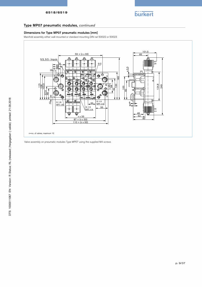
Type MP07 pneumatic modules, continued
Manifold assembly either wall-mounted or standard mounting DIN rail 50022 or 50023
59 + (n x 33)
5/2
5/3, 5/3 - Impuls
153542
55
3
1
5
G 1/8NPT 1/8
n x 3387 + (n x 33)
110 + (n x 33)
G 1/4NPT 1/4
33
55
G 1/2NPT 1/2
5
1
3
115
108
102,
557
,548
10
24 5892
120
182
101,565
68
4652
90
249
124,
8
100
82ø
5,5
Dimensions for Type MP07 pneumatic modules [mm]
Valve assembly on pneumatic modules Type MP07 using the supplied M4 screws
n=no.ofvalves,maximum12

6518/6519
p. 10/37
18
1846
M328
1827
,51,
5
Accessories Features Article no.
Capnut Capnutinstainlesssteelforadditionalprotectionoftheexhaustairchannelfromthepenetrationofdamp
649554
Blankingplug G⅛" 780141G¼" 780142G½" 780144
Silencer G⅛" 005305G¼" 005064G½" 005062
Labellingplate 64pieces 635416
Ordering chart for further accessories
Voltage [V] Max. current [mA] Article no.
24V 315mA 153733110V 50mA 153716230V 32mA 153715
Semi-delay fuse for 6519 NAMUR Ex m
Accessories
Dimensions Type 2508 [mm]
18
18
46
M328
1827
,51,
5Cable plug 2508 acc. to DIN EN 175301-803 Form AThe delivery of a cable plug includes the flat seal and the fixing screw. For other cable plug versions acc. to DIN EN 175301-803 Form A (previously DIN 43650) with integrated circuitry, see datasheet Type 2508.
Flatseal
Fixingscrew
18
18
46
M328
1827
,51,
5Ordering chart
Cable plug 2508Beschaltung Voltage Article no.
For standard version 6518/19 Fixingscrewinsteel(galvanisedandchrome-plated)withoutcircuitry 0-250V 008376withLED 12-24V 008360withLEDandvaristor 12-24V 008367withLEDandvaristor 200-240V 008369
For Ex i version 6519 Fixingscrewinstainlesssteel1.4404andbluecompressionglandnutwithoutcircuitry 0-250V 438574forfurtherversionsseedatasheet2508
Cable plug Type 2513 acc. to DIN EN 175301-803, Form AMeets the requirements of ATEX category 3 GD
BN
BU
GNYE
Ca
ble
le
ng
th[m
m]
Art
icle
n
o.
[in
mm
]
12000 2608935000 2608923000 260891300 260890

6518/6519
p. 11/37
Accessories (continued)
Ex-Cable glands (polyamideversionincludedindelivery/surchargeappliedforbrassnickelplatedversion
Special tool to turn the junction box (notincludedindelivery)
Ph
oto
De
scri
p-
tio
n
Art
icle
no
.
SetSC02-AC10SpecialwrenchServiceManual 293488
Ph
oto
De
scri
pti
on
Ex Approvals
Art
icle
no
Dra
win
g
Ce
rtifi
cati
on
Ide
nti
fica
-ti
on
Brass.nickel-plated,
6-13mm
PTB04ATEX1112X,IECExPTB13.0027X
II2GExeIICGb,II2DExtbIIICDbIP68, 773278
Polyamide,7-13mm
PTB13ATEX1015X,IECExPTB13.0034X
II2GExeIICGb,II2DExtbIIICDbIP68 773277
TL 29-37mmL 6mmD 20SW 24mmE 27mm
TL 36-45mmL 10mmD 20SW 24mmE 28mm

6518/6519
p. 12/37
Type 65195/2 way valve, circuit function H
Standard versions
*Mountinglengthwith2magneticcoils249mm
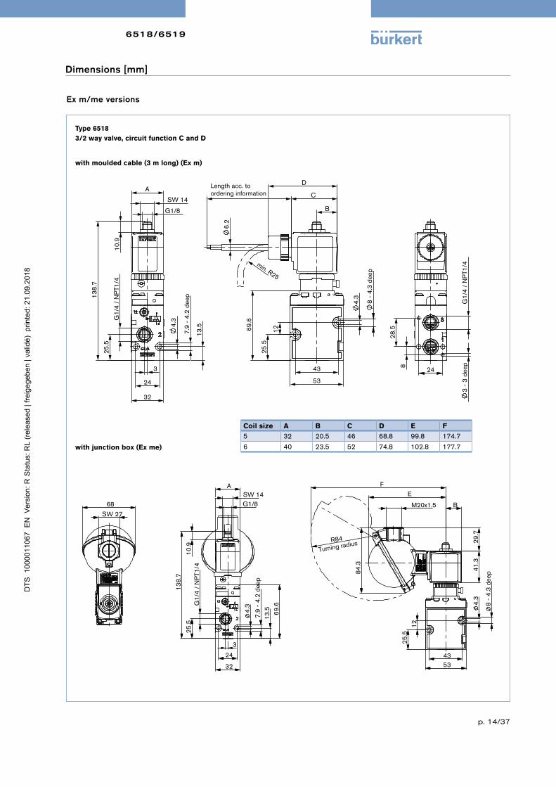
Dimensions [mm]
Type 65183/2 way valve, circuit function C and D
25.
5
12
69.
6
4.
3
8
- 4.
3 de
ep
43
53
45
20.5
4.
3
7.9
- 4
.2 d
eep
13.
5
24
32
G1/
4 /
NP
T1/4
25.
5
138
.7
11.
2
G1/8
SW 14
32
3
3
- 3
tief
G1/
4 /
NP
T1/4
8
28.
5
24
43
53
39.
6 3
6
4.
3
8
- 4.
3 de
ep
107
.7
45
20.5
24
32
4.
3
7.9
- 4
.2 d
eep
G1/
4 /
NP
T1/4
24
G1/8
SW 14
176
.8
32
11.
2
3
28.
5 2
6.5
24
48
G1/
4 /
NP
T1/4
3 -
3 de
ep

6518/6519
p. 13/37
Type 65195/3 way valve, circuit function L and N
Standard versions
Dimensions [mm]
112
50
36
44
43
45
4.
3
20.5
24
G1/
4 /
NP
T1/4
4.
5
11
- 3
dee
p
70
26
32
250
.2
G1/8
11.
2
SW 14
32
28.
5
3
- 3
deep
26.
5
48
G1/
4 /
NP
T1/4
24
5/2-Way- Pneumatic valve WWH-Impulse (WWZ)
5/3-Way- Pneumatic valve WWL and WWN
Standard version
6518/6519
p. 14/37
Ex m/me versions
with moulded cable (3 m long) (Ex m)
with junction box (Ex me)
Dimensions [mm]
Type 65183/2 way valve, circuit function C and D
25
5
12 69.
6
4.
3
8
- 4.
3 de
ep 43
53
D
6.
2
C ordering information
B
min. R25
Length acc. to
3
- 3
deep
G1/
4 /
NP
T1/4
8
28.
5
24
4.
3
7.9
- 4
.2 d
eep
13.
5
24
32
G1/
4 /
NP
T1/4
25.
5
138
.7
G1/8
SW 14
A
10.
9
3
25.
5 1
2
4.
3
8
- 4.
3 de
ep
43 53
29.
7
84.
3
R84
Turning radius
M20x1.5
E F
41.
3
B
4.
3
7.9
- 4
.2 d
eep
13.
5
24
32
G1/
4 /
NP
T1/4
2
5.5
138
.7
10.
9
G1/8 SW 14
A
69.
6
3
SW 27
68
Coil size A B C D E F
5 32 20.5 46 68.8 99.8 174.7
6 40 23.5 52 74.8 102.8 177.7

6518/6519
p. 15/37
Type 65195/2 way valve, circuit function H
with moulded cable (3 m long) (Ex m)
G1/
4 /
NP
T 1/
4 2
4
4.
5
11
- 3
dee
p
70
26
250
.2
G1/8 SW14
A
32
10.
9
D
36
44
4.
3
43
50
112
ordering information
6.
2
B C
min. R25
Length acc. to
48 2
8.5
26.
5
G1/
4 /
NP
T 1/
4
3
- 3
deep
24
Ex m/me versions
Dimensions [mm]
5/2 way valve, circuit function L and N
43
53
39.
6 3
6
4.
3
8 -
4.3
dee
p
107
.75
ordering information
6.
2
B
C
D
min. R25
length acc. to
28.
5 2
6.5
24
48
G1/
4 /
NP
T1/4
3
- 3
dee
p
24
32
4.
3
7.9
- 4
.2 d
eep
G1/
4 /
NP
T1/4
24
G1/8
SW 14
176
.85
A
10.
9

6518/6519
p. 16/37
Ex i versions
Type 65195/2 way valve, circuit function H
Type 65183/2 way valve, circuit function C
Dimensions [mm]
25,
5
12
4,
3
8
- 4,
3 tie
f
43
53
51
69,
6
23,5
3
- 3
tief
G1/
4 /
NP
T1/4
8
28,
5
24
4,
3
7,9
- 4
,2 ti
ef
13,
5
24
32
G1/
4 /
NP
T1/4
2
5,5
SW 14
145
,7
11,
2
G1/8
40
3
Ex i- Zulassung
43
53
39.
6 3
6
4.
3
8
- 4.
3 de
ep
107
.7
51
23.5
28.
5 2
6.5
24
48
G1/
4 /
NP
T1/4
3 -
3 tie
f
24
32
4.
3
7.9
- 4
.2 d
eep
G1/
4 /
NP
T1/4
24
G1/8
SW 14
183
.8
40
11.
2
3
Ex i Approval

6518/6519
p. 17/37
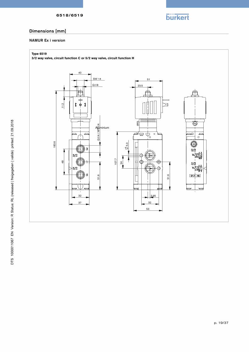
NAMUR Standard version
Dimensions [mm]
Type 65193/2 way valve, circuit function C or 5/2 way valve, circuit function H
5.
3
24
51.
6
32
53
45
107
.7
3.95
20.5
48
G1/
4 /
NP
T1/4
5
1.6
32
37
G1/8
32
SW 14
176
.8
11.
2
Standard version

6518/6519
p. 18/37
NAMUR Ex m/me version
with moulded cable (3 m long) (Ex m)
with junction box (Ex me)
Type 65193/2 way valve, circuit function C or 5/2 way valve, circuit function H
Dimensions [mm]
5.
3 2
4
51.
6
32
53
107
.7
D
6.
2
ordering information
3.95
B C
min. R25
Length acc. to
48
G1/
4 /
NP
T1/4
5
1.6
32
37
G1/8
A SW 14
176
.8
10.
9
SW27
68
48
G1/
4 /
NP
T1/4
5
1.6
32
37
5.
3 2
4
51.
6
32
53
107
.7
176
.8
41.
3 2
9.7
3.95
20.5
84.
3
M20x1.5
R84 Turning radius
E
F
Coil size A B C D E F
5 32 20.5 46 68.8 99.8 174.7
6 40 23.5 52 74.8 102.8 177.7
6518/6519
p. 19/37
Dimensions [mm]
NAMUR Ex i version
Type 6519 3/2 way valve, circuit function C or 5/2 way valve, circuit function H
5.
3
32
53
24
51.
6
107
.7
51
3.95
23.5 G1/8
SW 14
40
11.
2
183
.6 G
1/4
/ N
PT1
/4
48
51.
6
32
37
Ex i Approval
Aluminium

6519for extended
temperature range
p. 20/37
Technical data Aluminium Stainless steel
Orifice 9 9Body material
PilotvalveMainvalve
StainlesssteelAluminiumematalcoated
StainlesssteelStainlesssteel1.4571
Threaded socket material inaluminium instainlesssteelSeal material FPM,NBR PU,NBR,FPMMedium Neutralmedium,eglubricatedornon-lubricatedcompressedairCompressed air quality ISO8573-1:2010,Class7.2.4*Medium temperature -30°Cto+80°C -30°Cto+80°CAmbient temperature -40°Cto+80°C -30°Cto+80°CPneumatic connection
Supplyportconnection1,3,5Serviceport2,4
ThreadG¼,(onrequestNPT¼)ThreadG¼(onrequestNPT¼)
Operating voltages 24VDC24/110/230V/50-60Hz
Voltage tolerance +10%Electr. power consumption 2WDuty cycle 100%continuousoperationElectrical connection Tagconnectoracc.toDINEN175301-803(previouslyDIN
43650)FormAforcableplugType2508Type of protection IP65withcableplugInstallation Asrequired,preferablywithactuatorupright
Response times 5/2 5/2-bi 5/3 3/2 5/2 5/2-bi
Opening [ms] 16 18 16 13 12 14Closing [ms] 27 18 22 47 74 14
Type 6519 for extended standard temperature range
Ordering chart for valves in aluminium with manual override (withoutmanualoverrideonrequest)
All products come with a standard stainless steel cap nut. This cap nut protects the exhaust channel from penetrating humidity.
Cir
cuit
fu
nct
ion
Ori
fice
[m
m]
Se
al
ma
teri
al
an
d b
od
y
Thre
ad
ed
p
ort
co
nn
ect
ion
[i
nch
]
QN
n-v
alu
e
air
[l
/min
]
Pre
ssu
re
ran
ge
[ba
r]
We
igh
t [g
]
No
min
al
po
we
r [W
]
Vo
lta
ge
/F
req
ue
ncy
[V
/Hz]
Art
icle
no
.
5/2 WWH 9.0 FPM,NBR G¼" 1800 2.5-10 680 2 024/DC 231386024/50-60 231387110/50-60 231388230/50-60 231389
5/2-bistable WWZ 9.0 FPM,NBR G¼" 2100 2.5-10 990 2 024/DC 231390024/50-60 231391110/50-60 231392230/50-60 231393
5/3 WWL 9.0 FPM,NBR G¼" 1500 2.5-10 1060 2 024/DC 231394024/50-60 231395110/50-60 231396230/50-60 231397
5/3 WWN 9.0 FPM,NBR G¼" 1500 2.5-10 1060 2 024/DC 231399024/50-60 231400110/50-60 231401230/50-60 231402
* Topreventfreezingoftheexpandedcompressedair,thepressuredewpointmustbeatleast10Klowerthanthetem-peratureofthemedium.
1412
4 2
5 1 3
14 124 2
5 1 3
14 124 2
5 1 3
14 124 2
5 1 3

6519for extended
temperature range
p. 21/37
Ordering chart for valves in stainless steel with manual override (withoutmanualoverrideonrequest)
All products come with a standard stainless steel cap nut. This cap nut protects the exhaust channel from penetrating humidity.
Cir
cuit
fu
nct
ion
Ori
fice
[m
m]
Se
al
ma
teri
al
bo
dy
Thre
ad
ed
p
ort
co
nn
ect
ion
[i
nch
]
QN
n-v
alu
e
air
[l
/min
]
Pre
ssu
re
ran
ge
[ba
r]
We
igh
t [g
]
No
min
al
po
we
r [W
]
Vo
lta
ge
/F
req
ue
ncy
[V
/Hz]
Art
icle
no
.
5/2 WWH 8.0 PU,NBR G¼" 1980 3-10 1370 2 024/DC 231403024/50-60 231404110/50-60 231405230/50-60 231406
5/2-bistable WWZ 8.0 PU,NBR G¼" 1920 3-10 1680 2 024/DC 231407024/50-60 231408110/50-60 231409230/50-60 231410
5/3 WWL 8.0 PU,NBR G¼" 1770 3-10 1680 2 024/DC 231411024/50-60 231412110/50-60 231413230/50-60 231414
5/3 WWN 8.0 PU,NBR G¼" 1770 3-10 1680 2 024/DC 231415024/50-60 231416110/50-60 231417230/50-60 231418
1412
4 2
5 1 3
14 124 2
5 1 3
14 124 2
5 1 3
14 124 2
5 1 3

6519for extended
temperature range
p. 22/37
Type 6519 for extended Ex m temperature range
The maximum fluid temperature may never exceed the permissible temperature class (T4 135 °C, T5 100 °C, T6 85 °C) minus 5K.
x = on request
* Topreventfreezingoftheexpandedcompressedair,thepressuredewpointmustbeatleast10Klowerthanthetem-peratureofthemedium.
Ordering chart for valves in aluminium with manual override (withoutmanualoverrideonrequest)
All products come with a standard stainless steel cap nut. This cap nut protects the exhaust channel from penetrating humidity.
Cir
cuit
fu
nct
ion
Ori
fice
[m
m]
Se
al
ma
te-
ria
l b
od
y
Thre
ad
ed
p
ort
co
nn
ect
ion
[i
nch
]
QN
n-v
alu
e
air
[l
/min
]
Pre
ssu
re
ran
ge
[ba
r]
We
igh
t [g
]
No
min
al
po
we
r [W
]
Vo
lta
ge
/F
req
ue
ncy
[V
/Hz]
Art
icle
no
.
Type 6519 Ex m - with moulded cable, 3 m long1)
5/2 WWH 9.0 FPM,NBR G¼" 1800 2.5-10 680 3 024/UC 278217
110/UC x
230/UC 278220
5/2-bistable WWZ 9.0 FPM,NBR G¼" 2100 2.5-10 990 3 024/UC 278247
110/UC x
230/UC x
5/3 WWL 9.0 FPM,NBR G¼" 1500 2.5-10 1060 3 024/UC x
110/UC x
230/UC x
5/3 WWN 9.0 FPM,NBR G¼" 1500 2.5-10 1060 3 024/UC 278223
110/UC x
230/UC x
Technical data Aluminium Stainless steelOrifice 9 9Body material
PilotvalveMainvalve
StainlesssteelAluminiumematalcoated
StainlesssteelStainlesssteel1.4571
Threaded socket material inaluminium instainlesssteelSeal material FPM,NBR PU,NBR,FPMMedium Neutralmedium,e.g.lubricatedornon-lubricatedcom-
pressedairCompressed air quality ISO8573-1:2010,Class7.2.4*Medium temperature -30°Cto+80°C -30°Cto+80°CAmbient temperature -40°Cto+60°C -30°Cto+60°CPneumatic connection
Supplyportconnection1,3,5Serviceport2,4
ThreadG¼,(onrequestNPT¼)ThreadG¼(onrequestNPT¼)
Operating voltages 24VDC24/110/230V/50-60Hz
Voltage tolerance +10%Electr. power consumption 3WDuty cycle 100%continuousoperationElectrical connection 3mcable,moulded
junctionbox(withoutfuse)onrequestType of protection IP65Approvals
Coil
Junctionbox
PTB14ATEX2023X/IECExPTB14.0049XII2GExmbIICT5GbII2DExmbIIICT100°CDbEPS16ATEX1046X/IECExEPS16.0021XII2GEXebmbIICT5GbII2DEXmbtbIIICT100°CDb
Installation Asrequired,preferablywithactuatorupright
Response times 5/2 5/2-bi 5/3 3/2 5/2 5/2-biOpening [ms] 16 18 16 13 12 14Closing [ms] 27 18 22 47 74 14
1)Junctionboxversiononrequest
1412
4 2
5 1 3
14 124 2
5 1 3
14 124 2
5 1 3
14 124 2
5 1 3
6519for extended
temperature range
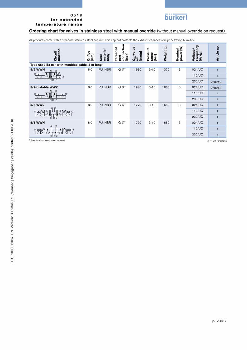
p. 23/37
Ordering chart for valves in stainless steel with manual override (withoutmanualoverrideonrequest)
All products come with a standard stainless steel cap nut. This cap nut protects the exhaust channel from penetrating humidity.
Cir
cuit
fu
nct
ion
Ori
fice
[m
m]
Se
al
ma
teri
al
bo
dy
Thre
ad
ed
p
ort
co
nn
ect
ion
[i
nch
]
QN
n-v
alu
e
air
[l
/min
]
Pre
ssu
re
ran
ge
[ba
r]
We
igh
t [g
]
No
min
al
po
we
r [W
]
Vo
lta
ge
/F
req
ue
ncy
[V
/Hz]
Art
icle
no
.
Type 6519 Ex m - with moulded cable, 3 m long1)
5/2 WWH 8.0 PU,NBR G¼" 1980 3-10 1370 3 024/UC x
110/UC x
230/UC 278219
5/2-bistable WWZ 8.0 PU,NBR G¼" 1920 3-10 1680 3 024/UC 278246
110/UC x
230/UC x
5/3 WWL 8.0 PU,NBR G¼" 1770 3-10 1680 3 024/UC x
110/UC x
230/UC x
5/3 WWN 8.0 PU,NBR G¼" 1770 3-10 1680 3 024/UC x
110/UC x
230/UC x
x = on request1)Junctionboxversiononrequest
1412
4 2
5 1 3
14 124 2
5 1 3
14 124 2
5 1 3
14 124 2
5 1 3
6519for extended
temperature range
p. 24/37
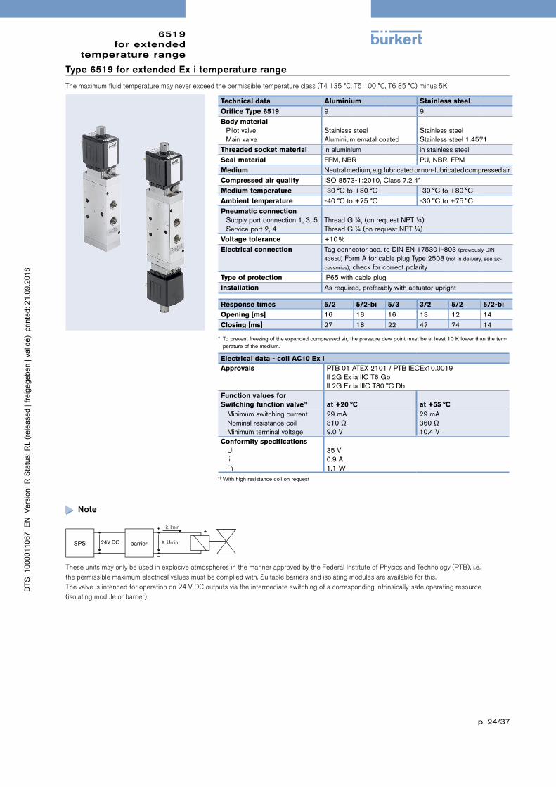
Type 6519 for extended Ex i temperature range
The maximum fluid temperature may never exceed the permissible temperature class (T4 135 °C, T5 100 °C, T6 85 °C) minus 5K.
Note
Technical data Aluminium Stainless steel
Orifice Type 6519 9 9Body material
PilotvalveMainvalve
StainlesssteelAluminiumematalcoated
StainlesssteelStainlesssteel1.4571
Threaded socket material inaluminium instainlesssteelSeal material FPM,NBR PU,NBR,FPMMedium Neutralmedium,e.g.lubricatedornon-lubricatedcompressedairCompressed air quality ISO8573-1:2010,Class7.2.4*Medium temperature -30°Cto+80°C -30°Cto+80°CAmbient temperature -40°Cto+75°C -30°Cto+75°CPneumatic connection
Supplyportconnection1,3,5Serviceport2,4
ThreadG¼,(onrequestNPT¼)ThreadG¼(onrequestNPT¼)
Voltage tolerance +10%Electrical connection Tagconnectoracc.toDINEN175301-803(previouslyDIN
43650)FormAforcableplugType2508(notindelivery,seeac-
cessories),checkforcorrectpolarityType of protection IP65withcableplugInstallation Asrequired,preferablywithactuatorupright
Response times 5/2 5/2-bi 5/3 3/2 5/2 5/2-bi
Opening [ms] 16 18 16 13 12 14Closing [ms] 27 18 22 47 74 14
* Topreventfreezingoftheexpandedcompressedair,thepressuredewpointmustbeatleast10Klowerthanthetem-peratureofthemedium.
Electrical data - coil AC10 Ex iApprovals PTB01ATEX2101/PTBIECEx10.0019
II2GExiaIICT6GbII2GExiaIIICT80°CDb
Function values forSwitching function valve1) at +20 °C at +55 °C Minimumswitchingcurrent Nominalresistancecoil Minimumterminalvoltage
29mA310Ω9.0V
29mA360Ω10.4V
Conformity specifications Ui Ii Pi
35V0.9A1.1W
1)Withhighresistancecoilonrequest
++
–
≥ lmin
≥ Umin24V DCSPS barrier
These units may only be used in explosive atmospheres in the manner approved by the Federal Institute of Physics and Technology (PTB), i.e., the permissible maximum electrical values must be complied with. Suitable barriers and isolating modules are available for this.The valve is intended for operation on 24 V DC outputs via the intermediate switching of a corresponding intrinsically-safe operating resource (isolating module or barrier).
6519for extended
temperature range
p. 25/37
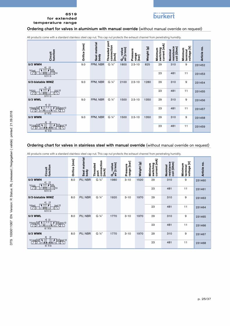
Ordering chart for valves in stainless steel with manual override (withoutmanualoverrideonrequest)
All products come with a standard stainless steel cap nut. This cap nut protects the exhaust channel from penetrating humidity.
Cir
cuit
fu
nct
ion
Ori
fice
[m
m]
Se
al
ma
teri
al
bo
dy
Thre
ad
ed
p
ort
co
nn
ect
ion
[i
nch
]
QN
n-v
alu
e
air
[l/
min
]
Pre
ssu
re
ran
ge
[b
ar]
We
igh
t [g
]
Min
imu
m
swit
chin
g
curr
en
t [m
A]
No
min
al
re
sist
an
ce
coil
[O
hm
]
Min
imu
m
term
ina
l vo
lta
ge
[V
]
Art
icle
no
.
5/2 WWH 8.0 PU,NBR G¼" 1980 3-10 1520 29 310 9 231460
23 481 11 231461
5/2-bistable WWZ 8.0 PU,NBR G¼" 1920 3-10 1970 29 310 9 231463
23 481 11 231464
5/3 WWL 8.0 PU,NBR G¼" 1770 3-10 1970 29 310 9 231465
23 481 11 231466
5/3 WWN 8.0 PU,NBR G¼" 1770 3-10 1970 29 310 9 231467
23 481 11 231468
Ordering chart for valves in aluminium with manual override (withoutmanualoverrideonrequest)
All products come with a standard stainless steel cap nut. This cap nut protects the exhaust channel from penetrating humidity.
Cir
cuit
fu
nct
ion
Ori
fice
[m
m]
Se
al
ma
teri
al
bo
dy
Thre
ad
ed
po
rt
con
ne
ctio
n
[in
ch]
QN
n-v
alu
e
air
[l/
min
]
Pre
ssu
re
ran
ge
[ba
r]
We
igh
t [g
]
Min
imu
m
swit
chin
g
curr
en
t [m
A]
No
min
al
re
sist
an
ce
coil
[O
hm
]
Min
imu
m
term
ina
l
volt
ag
e [
V]
Art
icle
no
.
5/2 WWH 9.0 FPM,NBR G¼" 1800 2.5-10 825 29 310 9 231452
23 481 11 231453
5/2-bistable WWZ 9.0 FPM,NBR G¼" 2100 2.5-10 1280 29 310 9 231454
23 481 11 231455
5/3 WWL 9.0 FPM,NBR G¼" 1500 2.5-10 1350 29 310 9 231456
23 481 11 231457
5/3 WWN 9.0 FPM,NBR G¼" 1500 2.5-10 1350 29 310 9 231458
23 481 11 231459
1412
4 2
5 1 3
14 124 2
5 1 3
14 124 2
5 1 3
14 124 2
5 1 3
1412
4 2
5 1 3
14 124 2
5 1 3
14 124 2
5 1 3
14 124 2
5 1 3

6519for extended
temperature range
p. 26/37
Type 6519 for extended NAMUR standard temperature range
Ordering chart for valves in aluminium with manual override (withoutmanualoverrideonrequest)
All products come with a standard stainless steel cap nut. This cap nut protects the exhaust channel from penetrating humidity.
Cir
cuit
fu
nct
ion
Ori
fice
[m
m]
Se
al
ma
teri
al
bo
dy
Thre
ad
ed
p
ort
co
nn
ect
ion
[i
nch
]
QN
n-v
alu
e
air
[l
/min
]
Pre
ssu
re
ran
ge
[ba
r]
We
igh
t [g
]
No
min
al
po
we
r [W
]
Vo
lta
ge
/F
req
ue
ncy
[V
/Hz]
Art
icle
no
.
3/2 WWC 6.0 FPM,NBR G¼" 780 3-10 540 2 024/DC 231469024/50-60 231470110/50-60 231471230/50-60 231472
5/2 WWH 6.0 FPM,NBR G¼" 800 3-10 540 2 024/DC 231473024/50-60 231474110/50-60 231475230/50-60 231476
5/2-bistable WWZ 6.0 FPM,NBR G¼" 900 3-10 540 2 024/DC 231477024/50-60 231478110/50-60 231479230/50-60 231480
Technical data Aluminium Stainless steel
Orifice 6 6Body material
PilotvalveMainvalve
StainlesssteelAluminiumematalcoated
StainlesssteelStainlesssteel1.4571
Threaded socket material inaluminium instainlesssteelSeal material FPM,NBR PU,NBR,FPMMedium Neutralmedium,e.g.lubricatedornon-lubricatedcom-
pressedairCompressed air quality ISO8573-1:2010,Class7.2.4*Medium temperature -30°Cto+80°C -30°Cto+80°CAmbient temperature -40°Cto+80°C -30°Cto+80°CPneumatic connection
Supplyportconnection1,3,5Serviceport2,4
ThreadG¼,(onrequestNPT¼)NAMURFlange
Operating voltages 24VDC24/110/230V/50-60Hz
Voltage tolerance +10%Electr. power consumption 2WDuty cycle 100%continuousoperationElectrical connection Tagconnectoracc.toDINEN175301-803(previouslyDIN
43650)FormAforcableplugType2508Type of protection IP65withcableplugInstallation Asrequired,preferablywithactuatorupright
Response times 5/2 5/2-bi 5/3 3/2 5/2 5/2-bi
Opening [ms] 16 18 16 13 12 14Closing [ms] 27 18 22 47 74 14
* Topreventfreezingoftheexpandedcompressedair,thepressuredewpointmustbeatleast10Klowerthanthetem-peratureofthemedium.
1412
4 2
5 1 3
2(A)
1(P) 3(R)
12
14 124 2
5 1 3

6519for extended
temperature range
p. 27/37
Ordering chart for valves in stainless steel with manual override (withoutmanualoverrideonrequest)
All products come with a standard stainless steel cap nut. This cap nut protects the exhaust channel from penetrating humidity.
Cir
cuit
fu
nct
ion
Ori
fice
[m
m]
Se
al
m
ate
ria
l b
od
y
Thre
ad
ed
p
ort
co
nn
ect
ion
[i
nch
]
QN
n-v
alu
e
air
[l/
min
]
Pre
ssu
re
ran
ge
[ba
r]
We
igh
t [g
]
No
min
al
po
we
r [W
]
Vo
lta
ge
/F
req
ue
ncy
[V
/Hz]
Art
icle
no
.
3/2 WWC 6.0 PU,NBR G¼" 1280 3-10 540 2 024/DC 231481024/50-60 231482110/50-60 231483230/50-60 231484
5/2 WWH 6.0 PU,NBR G¼" 1060 3-10 540 2 024/DC 231485024/50-60 231486110/50-60 231487230/50-60 231488
5/2-bistable WWZ 6.0 PU,NBR G¼" 1050 3-10 540 2 024/DC 231489024/50-60 231490110/50-60 231491230/50-60 231492
1412
4 2
5 1 3
2(A)
1(P) 3(R)
12
14 124 2
5 1 3

6519for extended
temperature range
p. 28/37
Type 6519 for extended NAMUR Ex m temperature rangeThe maximum fluid temperature may never exceed the permissible temperature class (T4 135 °C, T5 100 °C, T6 85 °C) minus 5K.
Ordering chart for valves in aluminium with manual override (withoutmanualoverrideonrequest)
All products come with a standard stainless steel cap nut. This cap nut protects the exhaust channel from penetrating humidity.
Cir
cuit
fu
nct
ion
Ori
fice
[m
m]
Se
al
ma
teri
al
bo
dy
Thre
ad
ed
p
ort
co
nn
ect
ion
[i
nch
]
QN
n-v
alu
e
air
[l/
min
]
Pre
ssu
re
ran
ge
[b
ar]
We
igh
t [g
]
No
min
al
po
we
r [W
]
Vo
lta
ge
/F
req
ue
ncy
[V
/Hz]
Art
icle
no
.
Type 6519 Ex m - with moulded cable, 3 m long1)
3/2 WWC 6.0 FPM,NBR G¼" 780 3-10 540 3 024/UC x
110/UC x
230/UC x
5/2 WWH 6.0 FPM,NBR G¼" 800 3-10 540 3 024/UC 278207
110/UC x
230/UC x
5/2-bistable WWZ 6.0 FPM,NBR G¼" 900 3-10 540 3 024/UC 278242
110/UC x
230/UC x
x = on request
Technical data Aluminium Stainless steel
Orifice 6 6Body material
PilotvalveMainvalve
StainlesssteelAluminiumematalcoated
StainlesssteelStainlesssteel1.4571
Threaded socket material inaluminium instainlesssteelSeal material FPM,NBR PU,NBR,FPMMedium Neutralmedium,e.g.lubricatedornon-lubricatedcompressedair
Compressed air quality ISO8573-1:2010,Class7.2.4*Medium temperature -30°Cto+80°C -30°Cto+80°CAmbient temperature -40°Cto+60°C -30°Cto+60°CPneumatic connection
Supplyportconnection1,3,5Serviceport2,4
ThreadG¼,(onrequestNPT¼)NAMURFlange
Operating voltages 24VDC24/110/230V/50-60Hz
Voltage tolerance +10%Electr. power consumption 3WDuty cycle 100%continuousoperationElectrical connection 3mcable,moulded
junctionbox(withoutfuse)onrequestType of protection IP65Approvals
Coil
Junctionbox
PTB14ATEX2023X/IECExPTB14.0049XII2GExmbIICT5GbII2DExmbIIICT100°CDbEPS16ATEX1046X/IECExEPS16.0021XII2GEXebmbIICT5GbII2DEXmbtbIIICT100°CDb
Installation Asrequired,preferablywithactuatorupright
Response times 5/2 5/2-bi 5/3 3/2 5/2 5/2-bi
Opening [ms] 16 18 16 13 12 14Closing [ms] 27 18 22 47 74 14
* Topreventfreezingoftheexpandedcompressedair,thepressuredewpointmustbeatleast10Klowerthanthetemperatureofthemedium.
1)Junctionboxversiononrequest
2(A)
1(P) 3(R)
12
14 124 2
5 1 3
1412
4 2
5 1 3

6519for extended
temperature range
p. 29/37
Ordering chart for valves in stainless steel with manual override (withoutmanualoverrideonrequest)
All products come with a standard stainless steel cap nut. This cap nut protects the exhaust channel from penetrating humidity.
Cir
cuit
fu
nct
ion
Ori
fice
[m
m]
Se
al
ma
teri
al
bo
dy
Thre
ad
ed
p
ort
co
nn
ect
ion
[i
nch
]
QN
n-v
alu
e
air
[l
/min
]
Pre
ssu
re
ran
ge
[ba
r]
We
igh
t [g
]
No
min
al
po
we
r [W
]
Vo
lta
ge
/F
req
ue
ncy
[V
/Hz]
Art
icle
no
.
Type 6519 Ex m - with moulded cable, 3 m long1)
3/2 WWC 6.0 PU,NBR G¼" 1280 3-10 960 3 024/UC x
110/UC x
230/UC x
5/2 WWH 6.0 PU,NBR G¼" 1060 3-10 960 3 024/UC x
110/UC x
230/UC x
5/2-bistable WWZ 6.0 PU,NBR G¼" 1050 3-10 1260 3 024/UC x
110/UC x
230/UC x
x = on request1)Junctionboxversiononrequest
2(A)
1(P) 3(R)
12
14 124 2
5 1 3
1412
4 2
5 1 3

6519for extended
temperature range
p. 30/37
Type 6519 for extended NAMUR Ex i temperature range
The maximum fluid temperature may never exceed the permissible temperature class (T4 135 °C, T5 100 °C, T6 85 °C) minus 5K.
Technical data Aluminium Stainless steelOrifice Type 6519 6 6Body material
PilotvalveMainvalve
StainlesssteelAluminiumematalcoated
StainlesssteelStainlesssteel1.4571
Threaded socket material inaluminium instainlesssteelSeal material FPM,NBR PU,NBR,FPMMedium Neutralmedium,e.g.lubricatedornon-lubricatedcompressedairCompressed air quality ISO8573-1:2010,Class7.2.4*Medium temperature -30°Cto+80°C -30°Cto+80°CAmbient temperature -40°Cto+75°C -30°Cto+75°CPneumatic connection
Supplyportconnection1,3,5Serviceport2,4
ThreadG¼,(onrequestNPT¼)NAMURFlange
Voltage tolerance +10%Electrical connection Tagconnectoracc.toDINEN175301-803(previouslyDIN
43650)FormAforcableplugType2508(notindelivery,
seeaccessories),checkforcorrectpolarityType of protection IP65withcableplugInstallation Asrequired,preferablywithactuatorupright
Response times 5/2 5/2-bi 5/3 3/2 5/2 5/2-biOpening [ms] 16 18 16 13 12 14Closing [ms] 27 18 22 47 74 14
* Topreventfreezingoftheexpandedcompressedair,thepressuredewpointmustbeatleast10Klowerthanthetemperatureofthemedium.
Electrical data - coil AC10 Ex iApprovals PTB01ATEX2101/PTBIECEx10.0019
II2GExiaIICT6GbII2GExiaIIICT80°CDb
Function values forSwitching function valve*
at+20°C at+55°C
Minimum switching current 29mA 29mANominal resistance coil 310Ohm 360OhmMinimum terminal voltage 9.0V 10.4VConformity specifications
UiliPi
35V0.9A1.1W
++
–
≥ lmin
≥ Umin24V DCSPS barrier
Note
These units may only be used in explosive atmospheres in the manner approved by the Federal Institute of Physics and Technology (PTB), i.e., the permissible maximum electrical values must be complied with. Suitable barriers and isolating modules are available for this.The valve is intended for operation on 24 V DC outputs via the intermediate switching of a corresponding intrinsically-safe operating resource (isolating module or barrier).

6519for extended
temperature range
p. 31/37
Ordering chart for valves in stainless steel with manual override (withoutmanualoverrideonrequest)
All products come with a standard stainless steel cap nut. This cap nut protects the exhaust channel from penetrating humidity.
Cir
cuit
fu
nct
ion
Ori
fice
[m
m]
Se
al
ma
teri
-a
l b
od
y
Thre
ad
ed
p
ort
co
nn
ect
ion
[i
nch
]
QN
n-v
alu
e a
ir
[l/m
in]
Pre
ssu
re
ran
ge
[ba
r]
We
igh
t [g
]
Min
imu
m
swit
chin
g
curr
en
t [m
A]
No
min
al
resi
sta
nce
co
il [
Oh
m]
Min
imu
m
term
ina
l vo
lta
ge
[V]
Art
icle
no
.
3/2 WWC 6.0 PU,NBR G¼" 1280 3-10 1100 29 310 9 231526
23 481 11 231527
5/2 WWH 6.0 PU,NBR G¼" 1060 3-10 1100 29 310 9 231528
23 481 11 231529
5/2 bistable WWZ 6.0 PU,NBR G¼" 1050 3-10 1550 29 310 9 231530
23 481 11 231531
Ordering chart for valves in aluminium with manual override (withoutmanualoverrideonrequest)
All products come with a standard stainless steel cap nut. This cap nut protects the exhaust channel from penetrating humidity.
Cir
cuit
fu
nct
ion
Ori
fice
[m
m]
Se
al
ma
teri
al
bo
dy
Thre
ad
ed
p
ort
co
nn
ect
ion
[i
nch
]
QN
n-v
alu
e a
ir
[l/m
in]
Pre
ssu
re
ran
ge
[b
ar]
We
igh
t [g
]
Min
imu
m
swit
chin
g
curr
en
t [m
A]
No
min
al
resi
sta
nce
co
il [
Oh
m]
Min
imu
m
term
ina
l vo
lta
ge
[V]
Art
icle
no
.
3/2 WWC 6.0 FPM,NBR G¼" 780 3-10 690 29 310 9 231520
23 481 11 231521
5/2 WWH 6.0 FPM,NBR G¼" 800 3-10 690 29 310 9 231522
23 481 11 231523
5/2 bistable WWZ 6.0 FPM,NBR G¼" 900 3-10 1140 29 310 9 231524
23 481 11 231525
2(A)
1(P) 3(R)
12
2(A)
1(P) 3(R)
12
14 124 2
5 1 3
14 124 2
5 1 3
1412
4 2
5 1 3
1412
4 2
5 1 3

6519for extended
temperature range
p. 32/37
Accessories Features Article no.
Capnut Capnutinstainlesssteelforadditionalprotectionoftheexhaustchannelfrom
penetratinghumidity,
649554
Blankingplug G¼ 780142Silencer G¼ 005064Labellingplate 64pieces 635416
Ordering chart for further accessories
Voltage [V] Max. current [mA] Article no.
24V 315mA 153733110V 50mA 153716230V 32mA 153715
Semi-delay fuse for 6519 NAMUR Ex m
Accessories
Dimensions Type 2508 [mm]
18
18
46
M328
1827
,51,
5Cable plug 2508 acc. to DIN EN 175301-803 Form AIncluded in delivery is a connector with flat seal and fixing screw. For other cable plug versions acc. to DIN EN 175301-803 Form A (previously DIN 43650)
with integrated circuitry, see datasheet Type 2508.Flatseal
Fixingscrew
18
1846
M328
1827
,51,
5
18
18
46
M328
1827
,51,
5
Ordering chart for cable plug 2508
Circuit Voltage Article no.
For standard version 6519 fixing screw in steel (galvanisedandchrome-plated)withoutcircuitry 0-250V 008376withLED 12-24V 008360withLEDandvaristor 12-24V 008367withLEDandvaristor 200-240V 008369
For Ex i version 6519 Fixingscrewinstainlesssteel1.4404andbluecompressionglandnutwithoutcircuitry 0-250V 438574forfurtherversionsseedatasheet2508
Cable plug Type 2513 acc. to DIN EN 175301-803, Form AMeets the requirements of ATEX category 3 GD
BN
BU
GNYE
Ca
ble
le
ng
th[m
m]
Art
icle
n
o.
[in
mm
]12000 2608935000 2608923000 260891300 260890

6519for extended
temperature range
p. 33/37
Accessories (continued)
Ex-Cable glands (polyamideversionincludedindelivery/surchargeappliedforbrassnickelplatedversion
Special tool to turn the junction box (notincludedindelivery)
Ph
oto
De
scri
p-
tio
n
Art
icle
no
.
SetSC02-AC10SpecialwrenchServiceManual 293488
Ph
oto
De
scri
pti
on
Ex Approvals
Art
icle
no
Dra
win
g
Ce
rtifi
cati
on
Ide
nti
fica
-ti
on
Brass.nickel-plated,
6-13mm
PTB04ATEX1112X,IECExPTB13.0027X
II2GExeIICGb,II2DExtbIIICDbIP68, 773278
Polyamide,7-13mm
PTB13ATEX1015X,IECExPTB13.0034X
II2GExeIICGb,II2DExtbIIICDbIP68 773277
TL 29-37mmL 6mmD 20SW 24mmE 27mm
TL 36-45mmL 10mmD 20SW 24mmE 28mm

6519for extended
temperature range
p. 34/37
Dimensions [mm]
Version Variants A B D E H
Standard, Ex m Ex i Standard, Ex m Ex i Standard, Ex m Ex i
WWH Stainlesssteel
53.5 107 35 40.7 45 51 177.8 186.6
WWH Aluminium 43.5 97 35 40.7 45 51 167.8 176.6
WWH–Impulse,WWL,WWN Stainlesssteel
53.5 107 35 40.7 45 51 248.6 266.2
WWH–Impulse,WWL,WWN Aluminium 53.5 107 35 40.7 45 51 148.6 266.2
12
E
24
5.5
32
50
A
B
H
48
G1/4
A
D
G1/
4
24
4.3
24
66
30
WWH 12
E
32
24
5.5
A
B
50
H
D
G1/
4
24
4.3
66
24
30
G1/
4
48
A
WWH - Impulse. WWL. WWN
Threaded port versionWWH
12
E
24
5.5
32
50
A
B
H
48
G1/4
A
D
G1/
4
24
4.3
24
66
30
WWH 12
E
32
24
5.5
A
B
50
H
D
G1/
4
24
4.3
66
24
30
G1/
4
48
A
WWH - Impulse. WWL. WWN
Threaded port versionWWH – Impulse, WWL, WWN

6519for extended
temperature range
p. 35/37
Dimensions [mm]
NAMUR versionWWC
NAMUR versionWWH
12
E
40
32
B
A24
H
D
25
44.35
C
10
14.5
G1/
444
12
E
64.8
B
A24
32
H
D
40
25
44.35
C
G1/
4
44
10
14.5
12
E
B
A24
32
40
H
D
25
44.35
C
44
G1/
4G
1/4
44
12.5
C
G1/
4
44
12.5
C
WWC
WWH
WWH - Impulse. WWL. WWN
12
E
40
32
B
A24
H
D
25
44.35
C
10
14.5
G1/
444
12
E
64.8
B
A24
32
H
D
40
25
44.35
C
G1/
4
44
10
14.5
12
E
B
A24
32
40H
D
25
44.35
C
44
G1/
4G
1/4
44
12.5
C
G1/
4
44
12.5
C
WWC
WWH
WWH - Impulse. WWL. WWN
Variant: stainless steel
Variant: aluminium
Version Variants A B C D E H
Standard, Ex m Ex i Standard, Ex m Ex i Standard, Ex m Ex i
WWC Stainlesssteel
35 94 25 35 40.7 45 51 165 173.8
WWC Aluminium 25 84 15 35 40.7 45 51 155 163.8
WWH Stainlesssteel
35 94 47 35 40.7 45 51 165 173.8
WWH Aluminium 25 84 37 35 40.7 45 51 155 163.8
WWH–Impulse,WWL,WWN Stainlesssteel
35 94 47 35 40.7 45 51 236 253.6
WWH–Impulse,WWL,WWN Aluminium 35 94 47 35 40.7 45 51 236 253.6

6519for extended
temperature range
p. 36/37
Dimensions [mm]
Version Variants A B C D E H
Standard, Ex m Ex i Standard, Ex m Ex i Standard, Ex m Ex i
WWC Stainlesssteel
35 94 25 35 40.7 45 51 165 173.8
WWC Aluminium 25 84 15 35 40.7 45 51 155 163.8
WWH Stainlesssteel
35 94 47 35 40.7 45 51 165 173.8
WWH Aluminium 25 84 37 35 40.7 45 51 155 163.8
WWH–Impulse,WWL,WWN Stainlesssteel
35 94 47 35 40.7 45 51 236 253.6
WWH–Impulse,WWL,WWN Aluminium 35 94 47 35 40.7 45 51 236 253.6
NAMUR versionWWH – Impulse, WWL, WWN
12
E
40
32
B
A24
H
D
25
44.35
C
10
14.5
G1/
444
12
E
64.8
B
A24
32
H
D
40
25
44.35
C
G1/
4
44
10
14.5
12
E
B
A24
32
40
H
D
25
44.35
C
44
G1/
4G
1/4
44
12.5
C
G1/
4
44
12.5
C
WWC
WWH
WWH - Impulse. WWL. WWN
Variant: stainless steel
Variant: aluminium

6519for extended
temperature range
p. 37/37
Junction box
Dimensions - Atex Approvals [mm]
41.
3
84.
3
29.
7
R84
Turning radius
E
F
M20x1.5 B
27
68
A
Cable coil
6.
2
ordering information
B
C
D
min R25
Length acc. to
A
Incaseofspecialapplicationconditions,pleaseconsultforadvice.
Subjecttoalterations©ChristianBürkertGmbH&Co.KG 1809/17_EU-en_00891764
Coil size A B C D E F
5 32 20.5 46 68.8 99.8 174.7
6 40 23.5 52 74.8 102.8 177.7


![Bistable [2]Rotaxane Based Molecular Electronics ...thesis.library.caltech.edu/2030/10/Choi_Jang_Wook_2007.pdf · Bistable [2]Rotaxane Based Molecular Electronics: Fundamentals and](https://static.fdocuments.net/doc/165x107/5ec39875f0c68315cb72de5b/bistable-2rotaxane-based-molecular-electronics-bistable-2rotaxane-based.jpg)
