3.1.2.1 Transmission Line Segments · 3.1.2.3. Transmission Line Infrastructure . The 220 kV...
39
3.0 PROJECT DESCRIPTION 3.1.2.1 Transmission Line Segments The Proposed Project has been subdivided into six distinct geographically-defined segments, as identified in previously referenced Figure 3.1-3, Transmission Line Route Description. The existing 220 kV transmission lines within the six geographically-defined segments currently utilize a mixture of LSTs, TSPs, and wood structures. Approximately 5 TSPs, 183 H-frame structures, 426 LSTs, four- three pole structures, and approximately 560 miles of conductor would be removed as part of the Proposed Project. The proposed structure, groundwire, and conductor removal types and quantities, as well as the proposed new structure, groundwire, conductor, and concrete installation types and quantities described below are approximate and subject to change following the completion of final engineering. The existing structures and existing conductor would be removed and replaced within existing ROW, except for an approximately 3-mile portion of Segment 5. The Proposed Project 220 kV transmission line removals and installations are summarized in Table 3.1-B, Transmission 220 kV Removal and Installation per Segment. Table 3.1-B: Transmission 220 kV Removal and Installation per Segment* Seg. 1 Seg. 2 Seg. 3 Seg. 4 Seg. 5 Seg. 6 Total Proposed Project Removals Double Circuit Lattice Steel Tower 44 29 34 45 33 29 214 Single Circuit Lattice Steel Tower 1 0 82 64 34 31 212 H-Frame 0 0 0 62 65 56 183 Three Pole Structure 0 0 0 4 0 0 4 Single Circuit TSP 0 0 0 0 5 0 5 Conductor (miles) 59 31 120 144 108 96 558 OHGW (miles) 7 5 50 60 45 40 207 Proposed Project Installation Double Circuit Lattice Steel Tower 55 35 133 136 72 93 524 Double Circuit Tubular Steel Pole 0 4 0 0 36 0 40 Single Phase Tubular Steel Pole 6 0 0 0 0 0 6 Circuit Length (miles) 14 10 40 48 36 32 181 Conductor (miles) 87 67 264 320 250 211 1,199 OPGW (miles) 7 6 22 26 20 18 99 * The existing structure, groundwire, and conductor removal types and quantities, as well as the proposed new structure, groundwire, conductor, hardware, and concrete installation quantities described in this table are approximate and subject to change following the completion of final engineering. The Proposed Project would include the following 220 kV transmission line elements: Proponent’s Environmental Assessment Page 3-33 West of Devers Upgrade Project October 2013
Transcript of 3.1.2.1 Transmission Line Segments · 3.1.2.3. Transmission Line Infrastructure . The 220 kV...

3.0 PROJECT DESCRIPTION
3.1.2.1 Transmission Line Segments
The Proposed Project has been subdivided into six distinct geographically-defined segments, as identified in previously referenced Figure 3.1-3, Transmission Line Route Description.
The existing 220 kV transmission lines within the six geographically-defined segments currently utilize a mixture of LSTs, TSPs, and wood structures. Approximately 5 TSPs, 183 H-frame structures, 426 LSTs, four- three pole structures, and approximately 560 miles of conductor would be removed as part of the Proposed Project. The proposed structure, groundwire, and conductor removal types and quantities, as well as the proposed new structure, groundwire, conductor, and concrete installation types and quantities described below are approximate and subject to change following the completion of final engineering. The existing structures and existing conductor would be removed and replaced within existing ROW, except for an approximately 3-mile portion of Segment 5. The Proposed Project 220 kV transmission line removals and installations are summarized in Table 3.1-B, Transmission 220 kV Removal and Installation per Segment.
Table 3.1-B: Transmission 220 kV Removal and Installation per Segment* Seg. 1 Seg. 2 Seg. 3 Seg. 4 Seg. 5 Seg. 6 Total
Proposed Project Removals Double Circuit Lattice Steel Tower 44 29 34 45 33 29 214
Single Circuit Lattice Steel Tower 1 0 82 64 34 31 212
H-Frame 0 0 0 62 65 56 183 Three Pole Structure 0 0 0 4 0 0 4 Single Circuit TSP 0 0 0 0 5 0 5 Conductor (miles) 59 31 120 144 108 96 558 OHGW (miles) 7 5 50 60 45 40 207 Proposed Project Installation Double Circuit Lattice Steel Tower 55 35 133 136 72 93 524
Double Circuit Tubular Steel Pole 0 4 0 0 36 0 40
Single Phase Tubular Steel Pole 6 0 0 0 0 0 6
Circuit Length (miles) 14 10 40 48 36 32 181 Conductor (miles) 87 67 264 320 250 211 1,199 OPGW (miles) 7 6 22 26 20 18 99 * The existing structure, groundwire, and conductor removal types and quantities, as well as the proposed new
structure, groundwire, conductor, hardware, and concrete installation quantities described in this table are approximate and subject to change following the completion of final engineering.
The Proposed Project would include the following 220 kV transmission line elements:
Proponent’s Environmental Assessment Page 3-33 West of Devers Upgrade Project October 2013

3.0 PROJECT DESCRIPTION
• Segment 1 would be approximately 3.5 miles in length and extend south from San Bernardino Substation to the San Bernardino Junction and include the following existing 220 kV transmission lines: Devers-San Bernardino, Etiwanda-San Bernardino, San Bernardino-Vista, and El Casco-San Bernardino. Proposed work within Segment 1 would include the removal of approximately 44 existing double-circuit LSTs,9 one single-circuit LST, 59 miles of existing conductor, and 7 miles of existing overhead ground wire (OHGW). Proposed work would also include the installation of approximately 55 double-circuit LSTs, 6 single-phase TSPs, 87 miles of new conductor, and 7 miles of new Optical Ground Wire (OPGW). The newly rebuilt 220 kV transmission lines in this segment would connect to the existing 220 kV switchrack inside San Bernardino Substation.
• Segment 2 would be approximately 5 miles in length and extends west from the San Bernardino Junction to Vista Substation and includes the following existing 220 kV transmission lines: Devers-Vista No. 1 and Devers-Vista No. 2. Proposed work within Segment 2 would include the removal of approximately 29 double-circuit LSTs, 31 miles of conductor, and 5 miles of OHGW. Proposed work would also include the installation of, approximately 35 double-circuit LSTs, 4 double-circuit TSPs, 67 miles of new conductor, and 6 miles of new OPGW. The newly rebuilt 220 kV transmission lines in this segment would connect to the existing 220 kV switchrack inside Vista Substation.
• Segment 3 would be approximately 10 miles in length and extends east from the San Bernardino Junction to El Casco Substation and includes the following existing 220 kV transmission lines: Devers-Vista No. 1, Devers-Vista No. 2, El Casco-San Bernardino, and Devers-San Bernardino. Proposed work within Segment 3 would include the removal of approximately 34 double-circuit LSTs, 82 single-circuit LSTs 120 miles of conductor, and 50 miles of OHGW. Proposed work would also include the installation of, approximately 133 double-circuit LSTs, 264 miles of new conductor, and 22 miles of new OPGW. The newly rebuilt El Casco-San Bernardino 220 kV transmission line in this segment would connect to the existing 220 kV switchrack inside El Casco Substation.
• Segment 4 would be approximately 12 miles in length and extends east from the El Casco Substation to San Gorgonio Avenue in the City of Banning and includes the following existing 220 kV transmission lines: Devers-Vista No. 1, Devers-Vista No. 2, Devers-El Casco, and Devers-San Bernardino. Proposed work within Segment 4 would include the removal of approximately 45 double-circuit LSTs, 64 single-circuit LSTs, 62 H-frame structures, four three pole structures, 144 miles of conductor, and 60 miles of OHGW. Proposed work would also include the installation of approximately 136 double-circuit LSTs, 320 miles of new conductor, and 26 miles of new OPGW. The newly rebuilt Devers-El Casco 220 kV transmission line in this segment would connect to the existing 220 kV switchrack inside El Casco Substation.
9 Removal of LSTs is further described in Section 3.2.3.13 Transfer/Removal of Existing Structures/Facilities.
Page 3-34 Proponent’s Environmental Assessment October 2013 West of Devers Upgrade Project

3.0 PROJECT DESCRIPTION
• Segment 5 would be approximately 9 miles in length and extends east from San Gorgonio Avenue in the City of Banning to the eastern limit of the Morongo Indian Reservation10 at Rushmore Avenue and includes the following existing 220 kV transmission lines: Devers-Vista No. 1, Devers-Vista No. 2, Devers-El Casco, and Devers-San Bernardino. Proposed work within Segment 5 would include the removal of approximately 33 double-circuit LSTs, 34 single-circuit LSTs, 65 H-frame structures, 5 TSPs, 108 miles of conductor, and 45 miles of OHGW. Proposed work would also include the installation of approximately 72 LSTs, 36 TSPs, 250 miles of new conductor, and 20 miles of new OPGW.
• Segment 6 would be approximately 8 miles in length and extends east from the eastern limit of the Morongo Indian Reservation at Rushmore Avenue to Devers Substation and includes the following existing 220 kV transmission lines: Devers-Vista No. 1, Devers-Vista No. 2, Devers-El Casco, and Devers-San Bernardino. Proposed work within Segment 6 would include the removal of approximately 29 double-circuit LSTs, 31 single-circuit LSTs, 56 H-frame structures, 96 miles of conductor, and 40 miles of OHGW. Proposed work would also include the installation of approximately 93 double-circuit LSTs, 211 miles of new conductor, and 18 miles of new OPGW. The newly rebuilt 220 kV transmission lines in this segment would connect to the existing 220 kV switchrack inside Devers Substation.
3.1.2.2 Vehicular Access and Spur Roads
SCE would need access roads to all facilities it plans to remove and/or construct as part of the Proposed Project. The transmission roads are classified into two groups: access roads and spur roads. Access roads are through roads that run between structure sites and serve as the main transportation route along the ROW. Spur roads branch off from access roads and terminate at one or more structure sites.
It is estimated that access to the WOD corridor for construction activities associated with the Proposed Project would be accomplished by utilizing a network of approximately 130 miles of existing access/spur roads, which will need to be rehabilitated for use, and constructing approximately 30 miles of new access/spur roads.11 SCE’s existing access roads are located within SCE ROW/easements. New and/or expanded property rights may be required to construct new access/spur roads.
The estimated length of new access/spur roads for each segment is summarized in Table 3.1-C, Approximate Miles of New Access Road per Segment.
10 Approximately 3 miles of existing WOD ROW through the Morongo Indian Reservation would be abandoned and replaced with a new 3-mile alignment pursuant to SCE-Morongo ROW agreement. In addition to this new 3 mile alignment, an alternative to the new 3-mile alignment (220 kV Transmission Line Route Alternative 1) is described in Section 3.14 Project Alternatives.
11 The proposed access/spur road mileages are approximate and are subject to change following the completion of final engineering.
Proponent’s Environmental Assessment Page 3-35 West of Devers Upgrade Project October 2013

3.0 PROJECT DESCRIPTION
Table 3.1-C: Approximate Miles of New Access and Spur Road per Segment Seg. 1 Seg. 2 Seg. 3 Seg. 4 Seg. 5 Seg. 6 Total
New Access and Spur Roads (miles) 2.3 2.7 10.3 6.3 5.2 3.2 30
The Proposed Project would utilize, to the extent practical, existing public roads and existing transmission access roads, including disturbed road shoulders. Construction of new permanent and/or temporary access roads for the Proposed Project would occur within existing and newly acquired ROW. With property owner approval, temporary construction activities outside of the ROW may be required in certain areas. Rehabilitation and/or upgrades to existing access roads may also be required to facilitate construction access and to support permanent operation and maintenance activities. In some locations, retaining wall-type structures would be installed to minimize extensive grading operations, minimize area of surface disturbance, and/or provide slope stabilization. Retaining walls are further described in Section 3.2.3.1, Access and Spur Roads.
The typical transmission access road consists of a network of (dirt or paved or both) roads accessed from paved public and private roads. The extent of access road construction and improvements would be dependent upon whether the roads would be used temporarily for construction activities only or kept for permanent access for operation and maintenance activities. Access and spur road construction details are described in Section 3.2.3.1, Access and Spur Roads.
3.1.2.3 Transmission Line Infrastructure
The 220 kV transmission line segments of the Proposed Project would utilize a combination of LSTs and TSPs. The approximate dimensions of the proposed structure types are shown in Figure 3.1-4, Typical Transmission Structures, and summarized in Table 3.1-D, Typical Transmission Structure Dimensions.
Table 3.1-D: Typical Transmission Structure Dimensions
Type of Structure
Proposed Number of Structures
Approximate Height Above
Ground
Approximate Pole
Diameter
Approximate Auger hole
Depth
Approximate Auger
Diameter LST 524 110 ft.–184 ft. N/A 15 ft.–50 ft. 3.0 ft.–7.0 ft. at
each leg TSP 40* 110 ft.–200 ft. 3.0 ft.–7.0 ft. 30 ft.–60 ft. 5 ft.–12 ft. TSP (single phase) 6** 65 ft.–120 ft. 3.0 ft.–7.0 ft. 30 ft.–60 ft. 5 ft.–12 ft.
Wood Pole with guys (single phase)
3 60 ft.- 80 ft. 2.0 ft.- 3.0 ft. 8 ft.- 12 ft. 4 ft. -5 ft.
Note: Specific structure type, foundation type, quantities, height, and spacing would be determined upon final engineering, and would be constructed in compliance with CPUC General Order 95. * Includes 36 TSPs in Segment 5 per agreement between SCE and Morongo. ** All single-phase TSPs will be located inside San Bernardino Substation.
Page 3-36 Proponent’s Environmental Assessment October 2013 West of Devers Upgrade Project

FIGURE 3.1-4
I:\SCE1110\G\Project Description\Typical Transmission Structures.cdr (5/31/13)
Note: This diagram is based on engineering which is subject to change as a result of the
CPUC permit process, final engineering, and any necessary adjustments during construction.
Typical Transmission Structures
Southern California EdisonWest of Devers Upgrade Project

3.0 PROJECT DESCRIPTION
This Page Intentionally Left Blank
Page 3-38 Proponent’s Environmental Assessment October 2013 West of Devers Upgrade Project

3.0 PROJECT DESCRIPTION
Lattice Steel Towers Approximately 524 lattice steel structures (LST) would be used for the Proposed Project. The footprint for LSTs would range from approximately 20 feet × 20 feet, to 42 feet × 42 feet, and extend approximately 110 feet to 184 feet aboveground.12 Each LST would use approximately 20 to 310 cubic yards of concrete. Each LST would be attached to four concrete foundations that would be approximately 3 feet to 7 feet in diameter and would extend underground approximately 15 feet to 50 feet with up to approximately 4 feet of concrete visible above ground. The typical conductor span length between structures would be approximately 850 feet. The LSTs would be all steel structures with a dulled galvanized finish. The vertical distance between conductor arms would be approximately 18.5 feet.
Tubular Steel Poles Approximately 40 TSPs would be used for the Proposed Project. The TSPs would be approximately 3 feet to 7 feet in diameter at the base and extend approximately 110 to 200 feet above ground. The TSPs would be attached to concrete foundations that would be approximately 5 feet to 12 feet in diameter and would extend underground approximately 30 feet to 60 feet with up to approximately 4 feet of concrete visible above ground. Each TSP would use approximately 25 cubic yards to 270 cubic yards of concrete. The typical conductor span length of TSPs would be approximately 650 feet between structures. The TSPs would be all steel structures with a dulled galvanized finish. The vertical distance between conductor arms would be approximately 18.5 feet. While the Proposed Project would primarily utilize double-circuit TSPs, approximately 6 single-phase TSPs could be used for the Proposed Project, depending on final engineering, in order to connect the new construction to the existing San Bernardino Substation 220 kV switchrack.
Other Structures Additionally, various types of temporary structures would be used throughout the Proposed Project to facilitate construction of the new 220 kV transmission lines. These temporary wood and/or steel structures would function as guard structures and/or shoo-fly structures, and are further described in Section 3.2.3.9, Guard Structures and Section 3.2.3.15, Shoo-Fly for additional information. These temporary structures would be direct-buried and/or guyed and removed following completion of construction for the particular location.
12 Some locations may require a larger LST footprint, depending on engineering requirements. As an example the structures needed to accommodate the Segment 6 crossing of the Whitewater River may utilize a structure footprint of 75 feet × 75 feet and extend approximately 110 feet to 204 feet aboveground.
Proponent’s Environmental Assessment Page 3-39 West of Devers Upgrade Project October 2013

3.0 PROJECT DESCRIPTION
3.1.2.4 Transmission Insulators and Conductors
Each transmission circuit typically includes three separate electrical phases. Each phase would consist of double-bundled (bundle of two conductors for each phase) 1,590 kcmil (one thousand circular mils) ACSR conductor. The conductors are made of aluminum strands with internal steel reinforcement and would have a non-specular finish. Polymer insulators would typically be used on all structures.
All transmission facilities would be designed consistent with Suggested Practices for Avian Protection on Power Lines: the State of the Art in 2006 (Avian Power Line Interaction Committee, 2006). All transmission facilities would be evaluated for potential collision risk and, where determined to be high risk, lines would be marked with collision reduction devices in accordance with Mitigating Bird Collisions with Power Lines: The State of the Art in 2012 (Avian Power Line Interaction Committee 2012).
3.1.2.5 Transmission Ground Wires
Overhead ground wires, including OPGW, would be installed on 220 kV transmission structures at or near the top of each structure. Where required, OHGW may also be utilized in addition to OPGW for additional shielding. The overhead steel ground wire would typically be ½ inch diameter extra high strength galvanized steel.
3.1.2.6 Subtransmission and Distribution Work Resulting from Transmission Lines
In order to accommodate installation of the new 220 kV transmission infrastructure within the existing ROW, existing 66 kV subtransmission lines and 12 kV distribution lines would need to be relocated. Please refer to Section 3.1.3, 66 kV Subtransmission Line Description for a complete description of the 66 kV subtransmission line relocation associated with the Proposed Project.
Distribution work resulting from 220 kV transmission portion of the Proposed Project would include overhead and underground construction and would be conducted in franchise or newly acquired utility ROW, as described below and seen in Figure 3.1-5, Subtransmission Line and Distribution Line Relocation Description:
• The Dental 12 kV circuit (Location 4, see Section 3.2.5, Distribution Relocation and Underbuild) would be relocated in a new underground system. The new underground system would consist of approximately 1.5 miles of duct bank, which would contain four 5-inch ducts, and use approximately eight 7 × 14 × 8-foot vaults and two 7 × 18 × 8-foot vaults. The new underground system would originate at Mission Road and Mountain View Avenue and extend southeasterly for approximately 1.5 miles to California Street. The 12 kV underground system would then extend south along California Street for approximately 500 feet to Barton Road. At this location, the 12 kV circuit would transition from underground to overhead via a distribution riser pole and connect to the existing Dental 12 kV circuit.
Page 3-40 Proponent’s Environmental Assessment October 2013 West of Devers Upgrade Project

SOURCE: Bing Maps (c.2010); SCE (5/2012, 2/2013)I:\SCE1110\GIS\MXD\GenEnvironmental\SubtransLineRoute.mxd (5/31/2013)
FIGURE 3.1-5
Southern California EdisonWest of Devers Upgrade Project
Relocated Subtransmission andDistribution Line Routes Description
Ã62
Ã60
Ã79 Ã243§̈¦10
§̈¦10
§̈¦215
Copyright:© 2009 ESRI
0 750 1500FEET
Detail Area
LEGEND
Proposed SB-Redlands-Tennessee UG 66kVProposed SB-Redlands-Timoteo UG 66kVExisting SB-Redlands-Tennessee OH 66kV andSB-Redlands-Timoteo OH 66kV to be Removed
Relocated 66kV Subtransmission Line RoutesTransmission Line Right-of-Way") Substations
Relocated 66kV Subtransmission Line RoutesProposed SB-Redlands-Tennessee OH 66kVProposed SB-Redlands-Timoteo OH 66kV
Relocated 12kV Distribution Line RoutesLocation 5 : Relocation of 12kV on Existing 66kV StructuresLocation 5: Underground System (Intern 12kV Circuit)
Relocated 12kV Distribution Line RoutesLocation 1: Removal of 12kV and Relocation on New 66kV StructureLocation 2: Removal of 12kV and Relocation on New 66kV StructureLocation 3: Removal of 12kV and Relocation on New 66kV StructureLocation 4: Underground System (Dental 12kV Circuit)

3.0 PROJECT DESCRIPTION
This Page Intentionally Left Blank
Page 3-42 Proponent’s Environmental Assessment October 2013 West of Devers Upgrade Project

3.0 PROJECT DESCRIPTION
• The Intern 12 kV circuit (Location 5) would be relocated in the same new underground system described for the Dental 12 kV circuit. The Intern 12 kV circuit would transition from overhead to underground via a distribution riser pole at Barton Road, then continue west from California Street for 0.5 mile to Mayberry Street, and then continue west on Barton Road for an additional 0.25 mile as underbuild (installing distribution circuit facilities under the 66 kV subtransmission circuit on the same structure) on an existing subtransmission pole line to the Segment 1 220 kV corridor. The new underbuild may require approximately 21 subtransmission structures to be replaced.
• The relocations of both the San Bernardino-Redlands-Timoteo 66 kV and the San Bernardino-Redlands-Tennessee 66 kV subtransmission lines would require the additional relocation of existing distribution circuits and associated equipment from existing poles to new subtransmission poles exclusively in Segment 1, as explained below:
o Location 1: Along Bryn Mawr Avenue between West Lugonia Avenue and the10 Freeway, relocate approximately 0.25 circuit miles of existing 12 kV distribution circuit and associated equipment to the new 66 kV subtransmission structure installed as part of the San Bernardino-Redlands-Timoteo 66 kV Subtransmission Line relocation. Approximately six 12 kV distribution poles would be removed.
o Location 2: Along Nevada Street between Almond Avenue and West Lugonia Avenue, relocate approximately 0.5 circuit miles of existing 12 kV distribution circuit and associated equipment to the new 66 kV subtransmission structures installed as part of the San Bernardino-Redlands-Tennessee 66 kV Subtransmission Line relocation. Approximately nine 12 kV distribution poles would be removed.
o Location 3: From Nevada Street for approximately 0.25 circuit miles along Citrus Avenue to Iowa Street and then extending south on Iowa Street for approximately for 0.25 circuit miles to Orange Avenue, relocate approximately 0.5 circuit miles of existing 12 kV distribution circuit and associated equipment to the new 66 kV subtransmission structures installed as part of the San Bernardino-Redlands-Tennessee 66 kV Subtransmission Line relocation. Approximately 19- 12 kV distribution poles would be removed.
Additional minor distribution relocations and associated work may be required after the completion of final engineering. The exact locations and extent of such work is not known at this time due to potential changes in the existing distribution system from the time of preparing this PEA and construction of the Proposed Project.
3.1.3 66 kV Subtransmission Line Description
The Proposed Project would require relocation of portions of the existing San Bernardino-Redlands–Timoteo and the San Bernardino-Redlands-Tennessee 66 kV
Proponent’s Environmental Assessment Page 3-43 West of Devers Upgrade Project October 2013

3.0 PROJECT DESCRIPTION
subtransmission lines located within Segment 1 to new routes within existing ROW or franchise, or newly acquired ROW).13 These two existing 66 kV subtransmission lines are currently located on approximately nine double-circuit LST and 28 double-circuit wood poles that would be removed from the existing Segment 1 ROW. Previously referenced Figure 3.1-5, Subtransmission Line and Distribution Line Relocation Description, depicts the proposed and existing subtransmission line routes.
3.1.3.1 San Bernardino-Redlands-Timoteo 66 kV Subtransmission Line Route
A portion of the existing San Bernardino- Redlands-Timoteo 66 kV Subtransmission Line would be removed and relocated outside of the existing WOD corridor.
The relocated single-circuit San Bernardino-Redlands-Timoteo 66 kV Subtransmission Line would connect to the existing San Bernardino Substation. The relocated 66 kV subtransmission line would exit San Bernardino Substation on existing poles and then transition underground to the east for approximately 800 feet within a new duct bank requiring the installation of two new vaults. The relocated 66 kV subtransmission line would then rise to an overhead position via a TSP riser pole that would be located along West San Bernardino Avenue. From the TSP riser pole, the 66 kV subtransmission line would transition to the south side of San Bernardino Avenue and extend approximately 1,350 feet along San Bernardino Avenue in a double-circuit configuration with the existing Calectric-Homart-Mentone 115 kV line. This portion of the line would extend to the corner of Marigold Avenue and would include the installation of approximately three TSPs, nine LWS/wood poles, and the removal of six wood poles. The 66 kV subtransmission line would then extend south for approximately 1,350 feet along a private property line to Almond Avenue and would include the installation of approximately one TSP and eight LWS/wood poles. The 66 kV subtransmission line would then extend west on Almond Avenue for approximately 600 feet. This portion of the subtransmission line would include the installation of approximately one TSP and four new LWS/wood poles. The 66 kV subtransmission line would extend south for 1,250 feet along an existing property line to Lugonia Avenue. This portion of the subtransmission line would include the installation of approximately one TSP and seven new LWS/wood poles. From this location, the 66 kV subtransmission line would proceed south overbuilt with existing distribution for about 1,200 feet to Interstate 10. This portion of the subtransmission line would include the installation of approximately one TSP and seven new LWS/wood poles. In order to accommodate the crossing of Interstate 10, the new 66 kV subtransmission line would require the installation of two new TSPs. From the south side of Interstate 10, the subtransmission line would extend south along Bryn Mawr Avenue for approximately 1,200 feet on approximately five new LWS/wood poles and would then transition from overhead to underground via a TSP riser pole. The 66 kV subtransmission line would be located underground for approximately 3,200 feet
13 The relocated subtransmission facilities would be outside of the existing 220 kV ROW but generally within the vicinity of the geographic area defined as Segment 1.
Page 3-44 Proponent’s Environmental Assessment October 2013 West of Devers Upgrade Project

3.0 PROJECT DESCRIPTION
from the TSP riser pole, south along a portion of Bryn Mawr Avenue (includes installation of one vault), and east along Redlands Boulevard (includes installation of one vault). Then it reaches an alley where it would proceed south (includes installation of one vault) and then west along the alley (includes installation of one vault) until it reaches Mountain View Avenue, where it would then rise to an overhead position via a TSP riser and extend overhead south for 160 feet to connect to the existing Timoteo Substation. This portion of the subtransmission line would include three LWS/wood poles.
In summary, the relocated single-circuit San Bernardino-Redlands-Timoteo 66 kV Subtransmission Line would be approximately 2 miles in length, constructed within new ROW or existing franchise14 and would include the following components:
• Installation of approximately 51 subtransmission LWS or wood poles, with associated guying, and approximately 11 TSPs;
• Installation of approximately 4,000 circuit feet of 3,000 kcmil underground conductor, approximately seven vaults (10 feet × 20 feet × 11 feet) and approximately 4,000 feet of new duct bank;
• Installation of approximately 7,100 circuit feet of 954 Stranded Aluminum Conductor (SAC) overhead conductor ; and
• Removal of six wood poles.
3.1.3.2 San Bernardino-Redlands-Tennessee 66 kV Subtransmission Line Route
A portion of the San Bernardino-Redlands-Tennessee 66 kV Subtransmission Line would be removed and relocated outside of the existing WOD corridor.
The relocated single-circuit San Bernardino-Redlands-Tennessee 66 kV Subtransmission Line would connect to the existing San Bernardino Substation. The relocated 66 kV subtransmission line would exit San Bernardino Substation on existing poles and then transition underground to the east for approximately 800 feet in a new duct bank requiring the installation of two new vaults. The relocated 66 kV subtransmission line would then rise to an overhead position via a TSP riser pole that would be located along West San Bernardino Avenue. From the TSP riser pole, the 66 kV subtransmission line would extend approximately 1,350 feet along San Bernardino Avenue to the corner of Marigold Avenue and would include the installation of approximately one TSP and nine LWS/wood poles. The 66 kV subtransmission line would then continue east along the south side of West San Bernardino Avenue in a double circuit configuration with the Calectric-Homart-Mentone 115 kV line for approximately 4,700 feet on approximately 26 LWS/wood poles and two TSPs to Nevada Street. The 66 kV subtransmission line would then extend south on Nevada Avenue for approximately 3,800 feet on
14 Franchise is a right or privilege conferred by agreement between SCE and local jurisdictions.
Proponent’s Environmental Assessment Page 3-45 West of Devers Upgrade Project October 2013

3.0 PROJECT DESCRIPTION
approximately 21 LWS/wood poles and four TSPs to Interstate 10. In order to accommodate the crossing of Interstate 10, the new 66 kV subtransmission line would require the installation of 3 new TSPs. From the south side of Interstate 10, the subtransmission line would extend south along Nevada Street for approximately 4,000 feet on approximately 20 LWS/wood poles and 2 TSPs to Citrus Avenue. The 66 kV subtransmission line would then extend east on Citrus Avenue for approximately 1,300 feet on approximately 11 LWS/wood poles and 1 TSP to Iowa Avenue. From Iowa Avenue, the 66 kV subtransmission line would extend south along Iowa Avenue for 2,700 feet on approximately 16 LWS/wood poles and 1 TSP where it would connect to the existing San Bernardino-Redlands-Tennessee 66 kV Subtransmission Line.
In summary, the relocated single-circuit San Bernardino-Redlands-Tennessee 66 kV Subtransmission Line would be approximately 3.5 miles in length, constructed within new ROW or existing franchise15 and would include the following components:
• Installation of approximately 103 subtransmission LWS or wood poles, with associated guying, and approximately 15 TSPs;
• Installation of approximately 800 circuit feet of 3,000 kcmil underground conductor, approximately two vaults (10 feet × 20 feet × 11 feet) and approximately 800 feet of new duct bank;
• Installation of approximately 18,480 of circuit feet 954 SAC overhead conductor; and
• Removal of 19 wood poles.
Additional minor subtransmission relocations and associated work may be required after the completion of final engineering of the 220 kV upgrades. The exact locations and extent of such work is not known at this time.
3.1.3.3 Subtransmission Structure Types
The 66 kV subtransmission segment of the Proposed Project would utilize a combination of LWS poles, wood poles, and TSPs.
3.1.3.4 Subtransmission Insulators and Conductor
The Proposed Project would utilize non-specular conductor with polymer insulators on all suspension/dead end structures.
A fault return conductor (FRC) would also typically be installed along LWS poles. Due to the combination of proposed wood poles, TSPs, and LWS poles that may be utilized, FRC may be installed on all poles for the entire length of subtransmission line route relocations. The FRC would typically be located approximately 1 to 2 feet above the telecommunications facilities, and approximately 4 to 6 feet below the distribution
15 The term “franchise” refers to utility infrastructure ROW agreements that SCE holds with local jurisdictions.
Page 3-46 Proponent’s Environmental Assessment October 2013 West of Devers Upgrade Project

3.0 PROJECT DESCRIPTION
facilities. To maintain proper clearances, the telecommunication facilities and distribution facilities may need to be rearranged. Approximately 25,580 circuit feet of FRC would be installed on subtransmission structures.
The 66 kV subtransmission structures would be designed following the intent of the Suggested Practices for Raptor Protection on Power Lines: the State of the Art in 2006 (Avian Power Line Interaction Committee 2006).
3.1.3.5 Subtransmission Structure Introduction
The approximate dimensions of the proposed structure types are shown in Figure 3.1-6, Typical Subtransmission Structures, and summarized in Table 3.1-E, Typical Subtransmission Structure Dimensions.
Table 3.1-E: Typical Subtransmission Structure Dimensions
Pole Type
Approximate Number of Structures
Approximate Height Above
Ground Approximate Pole Diameter
Approximate Auger hole
Depth
Approximate Auger
Diameter TSP 26 60 – 115 feet 3 – 6 feet 20 – 40 feet 4 – 8 feet LWS/Wood 146 60 – 100 feet 2 – 4 feet 7 – 12 feet 2 – 4 feet Guy Stub Poles 8 35 – 50 feet 2 – 4 feet 5 – 8 feet 2 – 4 feet
Note: Specific pole heights, number and types of poles, and spacing would be determined upon final engineering, and would be constructed in compliance with CPUC General Order 95.
3.1.3.6 Light Weight Steel/Wood Pole Description
Approximately 154 wood and/or LWS 66 kV poles would be used for the Proposed Project. The proportion of wood poles and LWS poles would be determined during final engineering. The wood and/or LWS poles would be direct buried to a depth of approximately 8 feet to 12 feet below the ground surface, and extend approximately 55 feet to 100 feet above the ground. The diameter of the wood and/or LWS poles would be approximately 2 to 4 feet at ground level and would taper to the top of the pole.
3.1.3.7 Guy Wires and Stub Pole Description (for Support)
Guy wire(s), and associated stub poles and/or anchors would be used where needed to support installation of new LWS and/or wood poles. Guying typically consists of installation of a guy wire (down guy) and attachment to a buried anchor. When there is not adequate space for the required down guy, a shorter guy pole (stub pole) is typically placed with a down guy and buried anchor in a location that has sufficient room for those facilities. Guy wires are used to stabilize LWS and wood poles located on curves or at corners along the line route. The height, depth, and diameter of stub poles and guy wire anchors would be determined on a case-by-case basis during final engineering. Guy stub poles range from 35 feet to 50 feet tall and the guy leads can stretch up to over 50 feet in length. Guy wires would be connected to a 10-foot screw/plate anchor that would be installed in the ground.
Proponent’s Environmental Assessment Page 3-47 West of Devers Upgrade Project October 2013

3.0 PROJECT DESCRIPTION
This Page Intentionally Left Blank
Page 3-48 Proponent’s Environmental Assessment October 2013 West of Devers Upgrade Project

FIGURE 3.1-6 Sheet 1 of 2
TUBULAR STEEL POLES
Notes: This diagram is based on engineering which is subject to change as a result of theCPUC permit process, final engineering, and any necessary adjustments during construction.
The height of each TSP will vary depending on the elevation at the top of each footing. The TSPconfigurations shown in these diagrams depict both direct buried and projected footings. Any TSPconfiguration could have a buried or projected footing, depending on terrain or other engineeringconsiderations.
TypicalFooting
I:\SCE1110\G\Project Description\Typical Subtransmission Structures.cdr (5/31/13)
Typical Subtransmission Structures
Southern California EdisonWest of Devers Upgrade Project
3.0 PROJECT DESCRIPTION
This Page Intentionally Left Blank
Page 3-50 Proponent’s Environmental Assessment October 2013 West of Devers Upgrade Project

FIGURE 3.1-6
Sheet 2 of 2
LIGHT WEIGHT STEEL/WOOD POLES
Note: This diagram is based on engineering which is subject to change as a result of the
CPUC permit process, final engineering, and any necessary adjustments during construction.
I:\SCE1110\G\Project Description\Typical Subtransmission Structures.cdr (5/31/13)
Typical Subtransmission Structures
Southern California EdisonWest of Devers Upgrade Project

3.0 PROJECT DESCRIPTION
This Page Intentionally Left Blank
Page 3-52 Proponent’s Environmental Assessment October 2013 West of Devers Upgrade Project

3.0 PROJECT DESCRIPTION
3.1.3.8 Subtransmission TSP Description
Approximately 26 TSPs would be used for the subtransmission component of the Proposed Project. The TSPs would be approximately 3 to 6 feet in diameter at the base and extend approximately 60 to 115 feet above ground. The TSPs would be attached to concrete foundations that would be approximately 4 to 8 feet in diameter and would extend underground approximately 20 to 40 feet with up to approximately 4 feet of concrete visible above ground. Each TSP foundation would use approximately 9 to 74 cubic yards of concrete. The TSPs would be all steel structures with a dulled finish.
3.1.3.9 Subtransmission Underground Description
As described in Section 3.1.3, 66 kV Subtransmission Line Description, underground 66 kV subtransmission facilities would be installed from San Bernardino Substation for approximately 800 feet along West San Bernardino Avenue to accommodate both the San Bernardino-Redlands-Timoteo 66 kV Subtransmission Line relocation and the San Bernardino-Redlands-Tennessee 66 kV Subtransmission Line relocation. The underground 66 kV subtransmission facilities portion of the San Bernardino-Redlands-Timoteo 66 kV Subtransmission Line route near Timoteo Substation would be approximately 3,100 feet from Bryn Mawr Avenue to Mountain View Avenue. The final determination on the number of required underground subtransmission vaults would be determined during final engineering; however, nine vaults have been estimated for purposes of the project description.
Trenches approximately 20–24 inches wide by a minimum of 63 inches deep would be required for installation of underground facilities. Following completion of trench excavation, duct banks would be installed in the trench, including conduit, spacers, ground wire, and concrete encasement. The duct bank typically consists of six 5-inch diameter polyvinyl chloride (PVC) conduits fully encased with a minimum of 3 inches of concrete all around. Typical subtransmission (66 kV) duct bank installations would accommodate six cables. The Proposed Project would utilize all six conduits for the first 800 feet (at San Bernardino Substation) and, for the remaining 2,300 feet, only three conduits would be utilized (near Timoteo Substation), leaving three spare conduits for any potential future circuit. The subtransmission duct banks would typically be installed in a vertically stacked configuration and each duct bank would be approximately 21 inches high by 20 inches wide.
Vaults are below-grade concrete enclosures that would be installed where the duct banks terminate. The inside dimensions of the underground vaults would be approximately 10 feet wide by 20 feet long with an inside height of 9.5 feet. The vaults would be placed no more than 1,500 feet apart along the proposed underground route. TSP riser poles would be located at the ends of each underground segment, at which the cables would transition from the underground duct bank to the overhead pole. The transition structure would support cable terminations, lightning arresters, and dead-end hardware for overhead conductors.
Proponent’s Environmental Assessment Page 3-53 West of Devers Upgrade Project October 2013

3.0 PROJECT DESCRIPTION
3.1.4 Federal Aviation Administration Considerations for Transmission and Subtransmission Lines
The alignment of the lines and terrain in the region may require Federal Aviation Administration (FAA) notification due to the above ground height of the conductor or OPGW between towers or the height of the transmission structures. As of the time of the preparation of this PEA, SCE anticipates that over the entire length of the Proposed Project (220 kV transmission lines component) approximately 165 structures would require FAA notification (49 structures in Segment 1; 8 structures in Segment 2; 0 structures in Segment 3; 16 structures in Segment 4; 84 structures in Segment 5; and 4 structures in Segment 6). The number of structures requiring FAA notifications will be updated following completion of final engineering. SCE would file the necessary FAA Form 7460 for structures or lines as outlined in FAA Part 77 upon completion of final engineering and prior to construction, per Federal Aviation Regulations (FAR) Part 77. To the extent practicable, FAA recommendations would be implemented into the design of the Proposed Project. If a span requires three or fewer marker balls, then the marker balls on the span would all be aviation orange. If a span requires more than three marker balls, then the marker balls would alternate between aviation orange, white, and yellow. Marker balls would be 36 inches in diameter. If a structure requires lighting, three red lights would be installed, one red flashing light at the peak/top and two red steady lights at the middle height of the tower. At the time of the preparation of this PEA and subject to subsequent FAA review, SCE anticipates that the FAA may recommend marker balls would be installed on approximately 110 spans and that lighting be installed on approximately 30 towers of the Proposed Project (220 kV transmission line component). However, the FAA has not conducted its review of the Proposed Project and thus has not issued any recommendations to date.
The alignment of the relocated 66 kV subtransmission lines, proximity to the San Bernardino Airport, and terrain in the region could also require FAA notification for certain subtransmission structures. The FAA notification process and installation of marker ball and structure lighting is the same as described above. At this time, SCE has neither determined nor been informed by the FAA as to whether marking and/or lighting of the 66 kV subtransmission line route spans or poles would be recommended. SCE will submit all relevant information, including any required Forms 7460-1 to the FAA, for the 66 kV subtransmission line routes where the Proposed Project would be constructed.
3.1.5 Telecommunications Description
Telecommunications infrastructure would be installed for the Proposed Project to provide for continued operation of SCE’s Supervisory Control and Data Acquisition (SCADA) network, protective relaying, data transmission, and telephone services during the Proposed Project construction, and for the continued operation of these services following construction.
The new telecommunications infrastructure would include additions and modifications to the existing telecommunications system. Those modifications would include work needed to maintain telecommunications operations during and after construction of the Proposed
Page 3-54 Proponent’s Environmental Assessment October 2013 West of Devers Upgrade Project
3.0 PROJECT DESCRIPTION
Project, work needed to facilitate the connection of existing substations to the new OPGW located on the new 220 kV structures, and ancillary work due to the modifications to accommodate the new OPGW and other modifications necessary to facilitate construction.
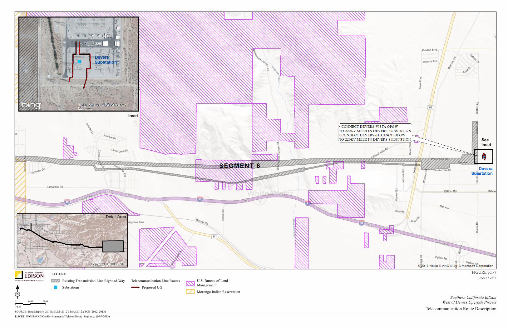
The following work is associated with maintaining telecommunications operations during and after construction of the Proposed Project and can be seen on Figure 3.1-7, Telecommunications Description:
• Connect the existing Vista-Moreno fiber optic cable to the MEER in El Casco Substation.
o Install approximately 42,000 feet of fiber optic cable on existing poles from a splice location on San Timoteo Canyon Road (near 12584 San Timoteo Road) to an existing riser pole located outside of El Casco Substation.
o Install approximately 2,300 feet of fiber optic cable in existing conduit and cable trench between the riser pole and the El Casco MEER.
• Connect the existing Devers-Valley OPGW to the MEER in Banning Substation.
o Install approximately 690 feet of fiber optic cable in new underground conduit between the existing Devers-Valley No. 2 500 kV structure M21-T3 to an existing distribution pole on Coyote Trail approximately 3,200 feet west of Old Idyllwild Road. From this existing distribution pole on Coyote Trail, install approximately 4,100 feet of new fiber optic cable east on existing distribution poles (combination of public and private lands) to a location 350 feet south of Old Idyllwild Road. From this location, install approximately 470 feet of fiber optic cable in new underground conduit to cross under the existing Devers-Valley 500 kV ROW to an existing distribution pole. From this location, install fiber optic cable overhead on a combination of distribution and subtransmission poles for approximately 2,100 feet to Wesley Street. The fiber optic cable would then extend east along Wesley Street for approximately 1,300 feet to existing SCE ROW and then north for approximately 3,300 feet to East Lincoln Street. The fiber optic cable would transition underground at this location and include the installation of approximately 230 feet of fiber optic cable and new underground conduit into the MEER at Banning Substation.
Proponent’s Environmental Assessment Page 3-55 West of Devers Upgrade Project October 2013

3.0 PROJECT DESCRIPTION
This Page Intentionally Left Blank
Page 3-56 Proponent’s Environmental Assessment October 2013 West of Devers Upgrade Project

LEGENDExisting Transmission Line Right-of-WaySubstationsJunctions
Telecommunication Line RoutesExisting OH Existing UG
Proposed OH FiberProposed UG Remove Existing OH
Copyright:© 2009 ESRI
Sheet 1 of 5
Detail Area
SOURCE: Bing Maps (c. 2010); BLM (2012); BIA (2012); SCE (2012, 2013)I:\SCE1110\GIS\MXD\GenEnvironmental\TelecomRoute_Seg1.mxd (10/9/2013)
FIGURE 3.1-7
Southern California EdisonWest of Devers Upgrade Project
Telecommunication Route Description0 1200 2400FEET

3.0 PROJECT DESCRIPTION
This Page Intentionally Left Blank
Page 3-58 Proponent’s Environmental Assessment October 2013 West of Devers Upgrade Project

LEGENDExisting Transmission Line Right-of-WaySubstationsJunctions
Telecommunication Line RoutesProposed UG
Copyright:© 2009 ESRI
Sheet 2 of 5
Detail Area
Inset
SeeInset
SOURCE: Bing Maps (c. 2010); BLM (2012); BIA (2012); SCE (2012, 2013)I:\SCE1110\GIS\MXD\GenEnvironmental\TelecomRoute_Seg2.mxd (10/9/2013)
FIGURE 3.1-7
Southern California EdisonWest of Devers Upgrade Project
Telecommunication Route Description0 800 1600FEET

3.0 PROJECT DESCRIPTION
This Page Intentionally Left Blank
Page 3-60 Proponent’s Environmental Assessment October 2013 West of Devers Upgrade Project

LEGENDExisting Transmission Line Right-of-WaySubstations
Telecommunication Line RoutesExisting OH Proposed OH ADSSProposed UGExisting UG OFNR
Copyright:© 2009 ESRI
Sheet 3 of 5
Detail Area
Inset 1
Inset 2SeeInset 1
SeeInset 2
SOURCE: Bing Maps (c. 2010); BLM (2012); BIA (2012); SCE (2012, 2013)I:\SCE1110\GIS\MXD\GenEnvironmental\TelecomRoute_Seg3.mxd (10/9/2013)
FIGURE 3.1-7
Southern California EdisonWest of Devers Upgrade Project
Telecommunication Route Description0 1500 3000FEET

3.0 PROJECT DESCRIPTION
This Page Intentionally Left Blank
Page 3-62 Proponent’s Environmental Assessment October 2013 West of Devers Upgrade Project

LEGENDExisting Transmission Line Right-of-WaySubstations
Telecommunication Line RoutesProposed OHProposed UGExisting OH
U.S. Bureau of LandManagementMorongo Reservation
Copyright:© 2009 ESRI
Sheet 4 of 5
Detail Area
See Inset 1
See Inset 2
Inset 1 Inset 2
SOURCE: Bing Maps (c. 2010); BLM (2012); BIA (2012); SCE (2012, 2013)I:\SCE1110\GIS\MXD\GenEnvironmental\TelecomRoute_Seg4.mxd (10/9/2013)
FIGURE 3.1-7
Southern California EdisonWest of Devers Upgrade Project
Telecommunication Route Description0 1900 3800FEET

3.0 PROJECT DESCRIPTION
This Page Intentionally Left Blank
Page 3-64 Proponent’s Environmental Assessment October 2013 West of Devers Upgrade Project
LEGENDExisting Transmission Line Right-of-WaySubstations
Telecommunication Line RoutesProposed UG
U.S. Bureau of LandManagementMorongo Indian Reservation
Copyright:© 2009 ESRI
Sheet 5 of 5
Detail Area
Inset
SeeInset
SOURCE: Bing Maps (c. 2010); BLM (2012); BIA (2012); SCE (2012, 2013)I:\SCE1110\GIS\MXD\GenEnvironmental\TelecomRoute_Seg6.mxd (10/9/2013)
FIGURE 3.1-7
Southern California EdisonWest of Devers Upgrade Project
Telecommunication Route Description0 1400 2800FEET

3.0 PROJECT DESCRIPTION
This Page Intentionally Left Blank
Page 3-66 Proponent’s Environmental Assessment October 2013 West of Devers Upgrade Project

3.0 PROJECT DESCRIPTION
• Connect the existing Devers-Valley OPGW to the MEER in Maraschino Substation.
o Install approximately 1,500 feet of fiber optic cable and new underground conduit from the existing Devers-Valley No. 2 500 kV structure M24-T3 to an existing distribution pole on Highland Springs Avenue approximately 300 feet south of Breckenridge Avenue. From this location, install approximately 1,700 feet of fiber optic cable on existing distribution poles along Highland Springs Avenue to approximately 190 feet south of Crooked Creek. At this location, the fiber optic cable would transition underground and extend approximately 2,900 feet in existing underground conduit north along Highland Springs Avenue to an existing vault approximately 300 feet north of Potrero Boulevard. From the existing vault, approximately 1,000 feet of fiber optic cable and new conduit would be installed to East First Street. From East First Street, the fiber optic cable and conduit would extend west for approximately 600 feet to an existing manhole. From the existing manhole, the fiber optic cable would extend west within existing underground conduit for approximately 12,600 feet to a distribution riser pole 200 feet west of Beaumont Avenue. From this location, the fiber optic cable would be installed overhead for approximately 3,200 feet on First Street to Veile Avenue. The fiber optic cable would then extend north on Veile Avenue on existing subtransmission poles for approximately 1,600 feet. From this location, the fiber optic cable would transition underground, and approximately 400 feet of fiber optic cable would be installed in an existing underground conduit and cable trench to the MEER located in Maraschino Substation.
• Connect the San Bernardino-Inland District Office fiber optic cable to the San Bernardino Substation through the proposed San Bernardino-San Bernardino Junction OPGW.
o Install approximately 200 feet of fiber optic cable and new underground conduit from the existing subtransmission pole located on the south side of Redlands Boulevard at the east edge of the WOD Corridor to the proposed OPGW splice location on a new 220 kV LST.
The following work would be conducted in order to facilitate the connection of existing substations to the new OPGW located on the new 220 kV structures:
• Connect Devers-Vista OPGW to the MEER in Banning Substation.
o From the new 220 kV structure, install approximately 500 feet of fiber cable and new underground conduit to an existing distribution pole located approximately 660 feet north of Summit Drive on San Gorgonio Avenue. The new fiber optic cable would connect to an existing fiber optic cable that extends to the MEER in Banning Substation.
• Connect Devers-Vista OPGW to the MEER in Maraschino Substation
o From the new 220 kV structure, install approximately 350 feet of fiber optic cable and new underground conduit to an existing manhole located on Oak View Drive approximately 320 feet north of Parkview Street. The new fiber optic cable would
Proponent’s Environmental Assessment Page 3-67 West of Devers Upgrade Project October 2013

3.0 PROJECT DESCRIPTION
connect to an existing fiber optic cable that extends to the MEER in Maraschino Substation.
• Connect the Devers-Vista OPGW to the MEER in El Casco Substation
o From the new 220 kV structure, install approximately 200 feet of fiber optic cable and new underground conduit to an existing manhole located in the existing SCE ROW immediately south of the El Casco Substation. The new fiber optic cable would connect to an existing fiber optic cable that extends to the MEER in El Casco Substation.
o From the new 220 kV structure, install approximately 200 feet of fiber optic cable and new underground conduit to an existing distribution pole located near structure M32-T3 of the existing Devers-Vista No. 2 220 kV ROW. The new fiber optic cable would connect to an existing fiber optic cable that extends to the MEER in El Casco Substation.
• Connect the Devers-Vista OPGW and Devers-El Casco OPGW to the MEER in Devers Substation.
o From the Devers-El Casco 220 kV structure, install approximately 80 feet of fiber optic cable and new underground conduit to an existing telecommunications manhole located inside the Devers Substation.
o From the southern Devers-Vista 220 kV structure, install approximately 329 feet of fiber optic cable and new underground conduit to an existing cable trench located inside the Devers Substation.
• Connect the Devers-El Casco OPGW and El Casco-San Bernardino OPGW to the MEER in El Casco Substation.
o From the Devers-El Casco 220 kV structure, install approximately 850 feet of fiber optic cable and new underground conduit to an existing distribution manhole located outside the El Casco Substation.
o From the El Casco-San Bernardino 220 kV structure, install approximately 200 feet of fiber optic cable and new underground conduit to an existing telecommunications manhole located outside the El Casco Substation.
• Connect the El Casco-San Bernardino OPGW and San Bernardino-Vista OPGW to the MEER in San Bernardino Substation.
o From the El Casco-San Bernardino 220 kV structure, install approximately 350 feet of fiber optic cable and new underground conduit to an existing manhole. Install approximately 1,550 feet of fiber optic cable in existing conduit and 60 feet of fiber optic cable in an existing cable trench to the MEER inside San Bernardino Substation.
o From the San Bernardino-Vista 220 kV structure, install approximately 350 feet of fiber optic cable and new underground conduit. Install approximately 315 feet of fiber optic cable in an existing cable trench to the MEER inside San Bernardino Substation.
Page 3-68 Proponent’s Environmental Assessment October 2013 West of Devers Upgrade Project
3.0 PROJECT DESCRIPTION
• Connect the Devers-Vista OPGW to the MEER in Vista Substation.
o From the 220 kV structure located inside Vista Substation, install approximately 1,000 feet of fiber optic cable and new underground structures to the MEER inside Vista Substation.
Additionally, due to uncertainty with construction sequencing and the need for existing telecommunications facilities to be relocated outside of the existing WOD corridor in a timely manner, an option to the connection for the San Bernardino Substation to the Inland District Office has been included for consideration in the environmental analysis.
From the MEER located inside San Bernardino approximately 2,000 feet of fiber optic cable would be installed in an existing conduit and cable trench to a riser pole located outside of San Bernardino Substation on San Bernardino Avenue. From this location, approximately 1,260 feet of fiber optic cable would be installed on existing subtransmission poles extending east to Marigold Avenue. From this location, the telecommunications facilities would then be co-located on the newly relocated San Bernardino-Redlands-Timoteo 66 kV Subtransmission Line. The co-location of telecommunications would require approximately 6,140 feet of fiber optic cable be installed on new subtransmission structures in private and public right of ways to the first structure on Bryn Mawr Avenue just north of the proposed subtransmission TSP riser pole. The telecommunications facilities would transition underground at this location which would require the installation of approximately 560 feet of new conduit and fiber optic cable to an existing pole on the south side of Redlands Boulevard just west of Bryn Mawr Avenue. At this location, the new fiber optic cable would then transition overhead via a telecommunications riser and would connect to the existing fiber optic cable.
The removal of the existing fiber optic cable (located on the OHGW) from the existing 220 kV towers is described in Section 3.1.2.1, Transmission Line Segments. Additionally, removal of the fiber optic portions from the 220 kV existing structures to connections in the field and/or at existing substations would be required and are described below:
• Removal of approximately 250 feet of fiber optic cable from conduit and 600 feet from a cable trench within Vista Substation.
• Removal of approximately 325 feet of fiber optic cable from conduit between existing tower M17-T2 (existing Devers-Vista No. 2 220 kV structure) and a riser pole 660 feet north of Summit Drive on San Gorgonio Avenue.
• Removal of approximately 225 feet of fiber optic cable from conduit between existing tower M24-T2 (existing Devers-Vista No. 2 220 kV structure) and the manhole located on Oak View Drive approximately 320 feet north of Parkview Street.
• Removal of approximately 120 feet of fiber optic cable from conduit between existing tower M29-T2 (existing Devers-Vista No. 2 220 kV structure) and existing manhole located in the SCE ROW immediately south of El Casco Substation.
Proponent’s Environmental Assessment Page 3-69 West of Devers Upgrade Project October 2013

3.0 PROJECT DESCRIPTION
• Removal of approximately 100 feet of fiber optic cable from existing conduit between tower M32-T3 (existing Devers-Vista No. 2 220 kV structure) and riser pole nearby.
• Removal of approximately 60 feet of fiber optic cable from conduit between existing tower M1-T1 (existing Devers-San Bernardino 220 kV structure) and riser pole on Redlands Boulevard.
The following ancillary work would be conducted to accommodate the new OPGW and other modifications necessary to facilitate construction of the Proposed Project:
• New telecommunication equipment would be installed in the MEERs at Vista, El Casco, Banning, Devers, San Bernardino, and Maraschino substations.
• During construction, temporary fiber optic jumpers (i.e., connectors) would be installed between the equipment inside the MEERs at Vista, El Casco, San Bernardino, Banning, Devers, Maraschino, Purewater, Mentone, Zanja, and Yucaipa substations to maintain telecommunication services, systems, and circuits. Temporary fiber optic jumpers would be used within a substation’s telecommunication facility to redirect and route the fiber optic systems and services during the Proposed Project’s construction phase. The new fiber optic terminal equipment is needed to compensate for the losses created by the redirected fiber optic routes.
3.1.6 Other Major Components
The Proposed Project would be constructed and operated in areas that may contain existing irrigation systems and other private infrastructure. In coordination with landowners, these systems and infrastructure may be temporarily removed, relocated, and/or replaced to facilitate the safe and efficient construction of the Proposed Project and to protect the current uses of private lands.
As previously explained, the project would utilize public roadways for construction. Use of public roadways may require repair due to construction traffic in some locations. The extent of such repair, if needed, would not be known until after construction activity has taken place.
The removal of the existing 220 kV transmission structures from the WOD corridor would result in the removal and possible relocation of approximately 12 existing cellular sites that are currently leased by SCE to various third-party providers (e.g., Verizon, T-Mobile, Sprint, AT&T, and Metro PCS). These cellular sites typically include cellular antennas and associated equipment that are attached to existing SCE transmission structures, or located immediately below or adjacent to those structures. These approximately 12 cellular sites are currently located in Segments 2, 3, 4, and 6 of the Proposed Project.
The exact location(s) to where these cellular sites would be relocated is not known at this time and cannot reasonably be forecasted due to the uncertainty of whether or where the existing third-party providers would need them in the future. Moreover, SCE would first need to complete final engineering of the proposed new WOD structure locations in order
Page 3-70 Proponent’s Environmental Assessment October 2013 West of Devers Upgrade Project

3.0 PROJECT DESCRIPTION
to identify where potential future cellular site locations might be located. The removal and possible relocation of these cellular sites would be an obligation of the third-party provider and would occur prior to the removal of the affected existing 220 kV transmission structures. In accordance with existing contract terms and conditions, SCE would provide notice to the third-party providers regarding the need for cellular site removal approximately one year prior to the start of the Proposed Project’s construction.
The relocation of the existing 66 kV subtransmission lines from the WOD corridor would require the removal and transfer of third-party telephone and cable services that are currently installed on SCE structures. Additionally, relocation of existing underground utilities such as water lines and gas pipeline may be required as well. For the same reasons explained above, additional information related to the scope of this work is not available at this time.
3.2 Proposed Project Construction Plan
The following subsections describe the construction activities associated with the Proposed Project.
For ease of comparison with the Alternative Project, the 220 kV transmission line land disturbance table and construction equipment and workforce estimates tables have been separated into two distinct tables each. Table 3.2-E1, Transmission Approximate Land Disturbance (Excluding Segment 5) and Table 3.2-H, Transmission (Excluding Segment 5) Construction Equipment and Workforce Estimates, include information related to Segments 1, 2, 3, 4, and 6. Table 3.2-E2, Transmission Approximate Land Disturbance (Segment 5), and Table 3.2-I, Transmission (Segment 5) Construction Equipment and Workforce Estimates, include information related to only Segment 5.
3.2.1 General Construction
3.2.1.1 Staging Areas
Construction of the Proposed Project would require the establishment of temporary staging yards. Staging yards would be used as a reporting location for workers, vehicle and equipment parking, and material storage. The yards may also have construction trailers for supervisory and clerical personnel. Staging yards may be lighted for staging and security. Normal maintenance and refueling of construction equipment would also be conducted at these yards. All refueling and storage of fuels would be performed in accordance with the Storm Water Pollution Plan (SWPPP).
SCE anticipates using one or more of the possible locations listed in Table 3.2-A, Potential Staging Yard Locations and seen in Figure 3.2-1, Potential Staging Yard Locations, as the staging yard(s) for the Proposed Project. Typically, each yard would be 3 to 20 acres in size, depending on land availability and intended use. Preparation of the staging yard would include temporary perimeter fencing and, depending on existing ground conditions at the site, grubbing the application of gravel or crushed rock. Power and telecommunications would be needed at the staging areas for the office trailer and
Proponent’s Environmental Assessment Page 3-71 West of Devers Upgrade Project October 2013