31-9207 Monogram Dishwasher With Top Controls ZBD9900RII Technical Service Guide
43
GE Appliances General Electric Company Louisville, Kentucky 40225 31-9207 Monogram Dishwasher with Top Controls ZBD9900RII Technical Service Guide March 2011 GE Appliances
-
Upload
appliance799 -
Category
Documents
-
view
21 -
download
4
description
31-9207 Monogram Dishwasher with Top Controls ZBD9900RII Technical Service Guide
Transcript of 31-9207 Monogram Dishwasher With Top Controls ZBD9900RII Technical Service Guide

GE AppliancesGeneral Electric CompanyLouisville, Kentucky 40225
31-9207
Monogram Dishwasherwith Top Controls
ZBD9900RII
Technical Service GuideMarch 2011
GE Appliances

– 2 –
IMPORTANT SAFETY NOTICE The information in this service guide is intended for use byindividuals possessing adequate backgrounds of electrical,electronic, and mechanical experience. Any attempt to repair amajor appliance may result in personal injury and property damage. The manufacturer or seller cannot be responsible for the in-terpretation of this information, nor can it assume any liability in con-nection with its use.
WARNING To avoid personal injury, disconnect power before servicing this product . If electrical power is required for diagnosis or test purposes, disconnect the power immediately after performing the necessary checks.
RECONNECT ALL GROUNDING DEVICES If grounding wires, screws, straps, clips, nuts, or washers used to complete a path to ground are removed for service, they mustbe returned to their original position and properly fastened.
GE AppliancesTechnical Service Guide
Copyright © 2011
All rights reserved. This service guide may not be reproduced in whole or in part,in any form, without written permission from the General Electric Company.

– 3 –
TABLE OF CONTENTS
Air Gap and Flow Meter .................................................................................................................................................31
Back Access Panel ............................................................................................................................................................27
Circulation Pump ...............................................................................................................................................................31
Component Locator Views ..........................................................................................................................................16
Control Panel Features ................................................................................................................................................... 8
Control Interface ...............................................................................................................................................................22
Detergent/Rinse Aid .........................................................................................................................................................24
Dishwasher Components ..............................................................................................................................................19
Door Hinge ...........................................................................................................................................................................25
Door Springs........................................................................................................................................................................25
Door Vent Fan .....................................................................................................................................................................24
Drain Pump ..........................................................................................................................................................................34
Drain Pump Check Valve ...............................................................................................................................................34
EMI Filter ................................................................................................................................................................................33
Escutcheon ..........................................................................................................................................................................21
Fault Codes .........................................................................................................................................................................36
Flow Meter ..........................................................................................................................................................................31
Heater ....................................................................................................................................................................................32
Inner Door Panel ...............................................................................................................................................................25
Inside Tub Components .................................................................................................................................................26
Installation ........................................................................................................................................................................... 7
Introduction ........................................................................................................................................................................ 6
Latch Assembly .................................................................................................................................................................23
Light Switch .........................................................................................................................................................................34
Lower Frame .......................................................................................................................................................................30
Main Control ........................................................................................................................................................................22
Main Control Programs ..................................................................................................................................................36
Main Control Testing........................................................................................................................................................21
Main ON/OFF Switch .......................................................................................................................................................22
Mini Manual Location ...................................................................................................................................................... 5
(Continued next page)

– 4 –
Nomenclature .................................................................................................................................................................... 5
Outer Door Panel ..............................................................................................................................................................20
Overfl ow Cut Out ..............................................................................................................................................................33
Pressure Sensor .................................................................................................................................................................29
Schematic.............................................................................................................................................................................42
Service Mode ......................................................................................................................................................................35
Special Tool ..........................................................................................................................................................................19
Thermistor ............................................................................................................................................................................33
Toe Kick Plate ......................................................................................................................................................................32
Troubleshooting ................................................................................................................................................................35
Troubleshooting Check List ..........................................................................................................................................37
Turbidity Sensor ................................................................................................................................................................32
Upper Basket ......................................................................................................................................................................19
Warranty ..............................................................................................................................................................................43
Washability Complaints ...............................................................................................................................................41
Water Level - How Does It Work? .............................................................................................................................28
Water Valve .........................................................................................................................................................................29

– 5 –
Model Designator
Nomenclature
Z B D 9 9 0 0 R I I
BrandZ = Monogram
Product Type BD = Built-In Dishwasher
Exterior ColorSS = Stainless Steel BB = Black WW = WhiteII = Custom panel and handle
required
Model Year Designator
Nomenclature
Model Number
The serial plate of your dishwasher is located on the tub wall, just outside the door.
The mini manual is located on the inside of the outer door panel.
Mini Manual
Serial NumberThe fi rst two characters of the serial numberidentify the month and year of manufacture.Example: FV123456S = March, 2011
F - MARG - APRH - MAYL - JUNM - JULR - AUGS - SEPT - OCTV - NOVZ - DECA - JANB - FEB
2011 - V2010 - T2009 - S2008 - R2007 - M2006 - L2005 - H2004 - G2003 - F2002 - D2001 - A2000 - Z
The letter des ig nat ing the year re peats every 12 years.
Example: V - 2011 V - 1999 V - 1987

– 6 –
Introduction
The new Monogram dishwasher is a brand new design with these following features:
• Hidden touch pad control panel on the top edge of the tall front door
• Larger tub with a height-adjustable upper basket and new cutlery basket
• New location for inlet valve, fl ow meter, and pressure sensor
• New dishwashing programs
• New Diagnostics to aid in troubleshooting problems
• New water level control
1
3
2
4
5
6
89
7
3
10
1. Upper basket2. Spray arms3. Lamp4. Cutlery basket5. Lower basket6. Dishwasher detergent compartment7. Main power switch8. Rinse Aid Compartment9. Filter10. Rating plate

– 7 –
Installation
The installation manual and hardware packet are located inside the machine. The toe kick plate comes packaged on the top of the Styrofoam packaging inside the shipping carton.
Snap the plastic glide feet onto the leveling legs to prevent damage to the fl oor. Please note that the unit weight is 101 lbs. and the glide feet can mar some soft wood fl oors. Caution should always be used when moving a unit into place.
Adjust the door springs
The door should remain balanced once opened. Both spring ends are turned clockwise to increase tension, and counterclockwise to decrease tension.
PEX water fi ll line
The PEX water fi ll line comes with a 3/8-in. compression nut that is intended to be connected to a shutoff valve with compression threads. If the home shutoff valve has a solder fi tting, cut the copper water line under the sink and join the copper and PEX materials with a 3/8-in. compression union.
Drain line
The high loop bracket comes attached to the unit at the ideal height. It should not be removed.
The drain line bracket can be repositioned to accommodate an installation or gain hose length by loosening the set screw and sliding the bracket along the back top ridge.
The power cord (approximately 42-in. long) comes already attached to the unit. The terminal block is set up so that the unit can be hardwired or a longer cord installed if needed.
The drain line comes with a graduated boot installed. This graduated boot is designed to accommodate 1/2-, 5/8-, 23/32-, and 7/8-in. connections.Height
WidthDepthWeightWater Pressure
ConnectionMax output
Specifi cations
33-7/8" _ 36"23 5/8"22 7/8" (without door)101 lbs4.2 _ 140 psi0.03 _ 1.0 Mpa0.3 _ 10 BarSingle phase, 120 V, 60 Hz, 15 A1200 W
Set Screw

– 8 –
AUTO WASHThe dishwasher detects how soiled the dishes are and adjusts water consumption and temperature accordingly.
HEAVY WASHThe HEAVY WASH program should be used for heavily soiled dishes, e.g. saucepans, pots and gratin dishes. If there is still space in the machine after loading such items, you can add plates etc.
NORMAL WASH
Used for washing normally soiled dishes such as plates, serving dishes, cups andglasses, etc.
LIGHT WASHIf the dishes are not heavily soiled, you can select the Light Wash cycle. This cycle is intended for glass and china which has just been used and therefore does not need a more powerful cycle.
SPEED WASH Select SPEED WASH if the dishes are very lightly soiled. This program is used for very lightly soiled glass and china, e.g. coffee cups.
RINSE ONLY For rinsing partial loads that will be washed later. Do not use detergent with thiscycle.
1
Select a cycle by pressing the CYCLE button until the required option is selected.
1 2 3 4 5 67
TEMP BOOST When selected, the cycle will run with a heating element on longer and may increase cycle time to improve both wash and dry performance.
2
DELAY START
If you want the machine to start later, press the DELAY START option button. The clock symbol on the button lights up. Then press the START/RESET button and the machine will start the program 5 hours later. To cancel DELAY START, hold down the START/RESET button for three seconds.
3
HEAT DRY Select this option to improve drying results.4
LOW RINSE AID Displayed when the rinse agent dispenser needs to be refilled.5
Control Panel Features
(Continued next page)

– 9 – (Continued next page)
PROGRAMS Average TotalCycle Time (Min)
Water Consumption(Gallons)
Auto 115 - 170 3.4 - 6.3Heavy 190 - 210 5.3Normal 105 - 140 4.0 - 5.8
Light 100 - 127 2.9Speed 20 - 64 2.6Rinse 4 - 22 0.8

– 10 –
Water Temperature
The entering water must be at least 120°F (49°C) and not more than 150°F (66°C), for effective cleaning and to prevent dish damage.
Check the water temperature with a candy or meat thermometer. Turn on the hot water faucet nearest the dishwasher, place the thermometer in
a glass and let the water run continuously into the glass until the temperature stops rising.
NOTE: This Dishwasher can be plumbed to the cold water faucet, but this is not recommended.
Use a Rinse Agent
A rinse agent improves dry performance, reduces spots and prevents new film buildup on your dishes, glasses, flatware, cookware and plastic. Cascade Crystal Clear® is the recommended rinse agent for Monogram Dishwashers.
The rinse agent dispenser holds 4.7 o . of rinse agent. Under normal conditions, this will last approximately one month. Try to keep it full, but do not overfill.
To fill the rinse agent dispenser, make sure the dishwasher door is fully open.
Rotate the dispenser cap counterclockwise and lift it out. Add rinse agent until the indicator window shows full.
Clean up any spilled rinse agent with a damp cloth. Replace the dispenser cap.
The amount of rinse agent released into the final wash can be adjusted. The factory setting is at the midpoint. If there are rings of calcium (hard water) spots on dishes, try a higher setting. If there is foaming, use a lower setting.
To adjust the setting, remove the dispenser cap; then turn the adjuster counterclockwise to increase the amount of rinse agent or clockwise to decrease the amount of rinse agent dispensed.
Lighting Features
Interior Lights
The interior Halogen lights provide better visibility for loading and unloading. They turn on when the door is opened and turn off when the door is latched.
Do not attempt to replace the bulbs. If light bulb replacement is necessary, please contact the GE Answer Center for service by calling 1.800.626.2000.
1. Compartment for main wash dishwash-er detergent2. Compartment for pre-wash detergent3. Rinse aid cover4. Detergent compartment cover
3 (Rinse agent adjuster is located under the cap)
4
1 2
1. Compartment for main wash dishwasher detergent
2. Compartment for pre-wash detergent
3. Rinse aid cover
4. Detergent Compartment cover
(Continued next page)

– 11 –
Water hardness Detergent amountsSoft(0-3 grains per gallon)
Prewash 1 teaspoonMain wash 1 to 1-1/2 tablespoons
Medium(4-8 grains per gallon)
Prewash 1 teaspoonMain wash 1 to 2 tablespoons
hard(9+ grains*)
Prewash 1 teaspoonMain wash 2 to 3 tablespoons
* 12 grains and higher is extremely hard water.
Recommended Detergent Amounts based on Water Hardness
Detergent Dosage
(Continued next page)
Fine fi ler
Debris that collects on the fi ne fi lter is aumatically rinsed away during each wash. However, the fi ne
Note: The dishwasher must not be used without the fi ler in place! An improperly fi tted coarse fi lter may affect the dishwashing result.
Spray arm
Coarse lter
Fine lter
Tubular strainer
The dishwasher’s inner container is made of stainless steel and is kept clean through normal use. However, if you have calciferous (hard) water, lime deposits can form in the dishwasher. In this case, run a normal wash program with two tablespoons of citric acid in the dishwasher detergent compartment.
Filters
The dishwasher utilizes a coarse fi lter and a fi ne fi lter.
Coarse fi ler
The coarse fi lter traps lager food particles, which cannot get past the drain pump. Empty the coarse fi lter as necessary.
1. Lift the coarse fi lter by the handle
2. Empty the coarse fi lter and replace it .
1x
3. Remove and clean the fi ne fi lter.
4. Replace in reverse order. Ensure that the edges are properly sealed when replacing the fi ne fi lter.
5. Lock the fi lter in place by turning the handle clockwise to the stop position. The handle should point out from the dishwasher.
1x
fi lter and its pipe section should be cleaned once or twice a year.
1. Turn the handle 1 full turn counterclockwise.
2. Lift the pipe section straight up by the handle and then lift the coarse fi lter to clean the pipe section.

– 12 –(Continued next page)
Door
When cleaning the edge around the door, use a slightly damp cloth. Do not use a spray bottle around the door catch. This is to ensure that water does not come into contact with the electrical components in the door catch.
Drain pump
The pump can be accessed from inside the machine.
WARNING: Disconnect the power from the machine
1. Remove the coarse fi lter and pipe section.
2. Remove the small fi tted piece at the left of the sump (see the image below).
3. The impeller blade can be checked and accessed from inside this sump opening.
4. Reinstall the fi tted piece and fi lters.
5. Insert the plug into the wall socket.
If the machine still does not start and a buzzing sound is heard, the overfl ow guard has been activated.
• Shut off the water.
• Pull the plug out from the wall socket.
• Call for service.
Note: Be sure to reinstall the fi tted piece.
The spray arms
Holes and bearings can sometimes become blocked.
1. Pull the lower washer arm straight up to release it .
2. Remove any deposits. The washer arms also have holes underneath.
3. Reassemble the washer arm before using the dishwasher.

– 13 –
Program Selection
(Continued next page)
Some of the dishwasher’s programs can changed by using the keypad. The new selection will be retained until the next time you use the keypad to reset this function.
Even if the machine is turned off at the main switch or loses power for any other reason, all selections registered before the interruption of power will be retained.
Child-safe button lock
You can prevent a child starting the machine by accident or changing the settings by programming the machine with a button lock, which requires the TEMP BOOST and HEAT DRY buttons to be pressed simultaneously to start up the machine. The button lock will automatically be reactivated after 3 minutes.
1. Switch off the dishwasher with the main switch.
2. Hold in the TEMP BOOST and HEAT DRY buttons while pressing the main switch. The Temperature, Drying, and Start symbols will fl ash. Release the TEMP BOOST and HEAT DRY buttons.
3. Press the CYCLE button – when the AUTO wash symbol is lit , the button lock has been activated.
4. Then press the START/RESET button to store the setting.
or Reset:
1. Switch off the dishwasher with the main switch.
2. Hold in the TEMP BOOST and HEAT DRY buttons at the same time as pressing the main switch.
3. Press the CYCLE button – when the AUTO wash symbol goes out, the button lock has been deactivated.
4. Then press the START/RESET button to confi rm the setting.

– 14 –
Setting a Signal
(Continued next page)
If you want the machine to signal when the wash is complete, you can program it to do this. The machine is set without a signal by default.
1. Switch off the dishwasher at the main switch.
2. Hold in the DELAY start button at the same time as you press the main switch. The button fl ashes. Release the button.
3. Press the CYCLE button – when the AUTO wash symbol lights, the signal is activated.
4. Press the START/RESET button and the setting will be stored until next time you want to make a change.
or Reset
1. Switch off the dishwasher with the main switch.
2. Hold in the DELAY start button at the same time as you press the main switch. The button fl ashes. Release the button.
3. Press the CYCLE button – when the AUTO wash symbol goes out, the signal is deactivated.
4. Press the START/RESET button and the setting will be stored until next time you want to make a change.

– 15 –
Child Lockout
1. Turn off main ON/OFF power switch.
2. Wait at least 5 seconds.
3. Press and hold the TEMP BOOST and HEAT DRY option pads.
4. Switch on main ON/OFF power switch.
5. Release TEMP BOOST and HEAT DRY pads after any indicator light comes on (approximately 3 seconds).
6. Use the CYCLE pad to select status. AUTO LED lit = child lockout is activated. AUTO LED unlit = child lockout is deactivated.
7. Confi rm the selection by pressing the START/RESET pad.
Temporary deactivation of the child lockout feature is achieved by pressing the TEMP BOOST and HEAT DRY pads together. Both indicator lights will fl ash if customer tries to start a cycle in the child lockout mode. After three minutes, child lockout is automat-ically reactivated.
Model Select Setting
The service technician must run a model select set-ting or the machine will not function. If the control is replaced, the machine will automatically be in the model select setting menu when the power supply is switched on for the fi rst time.
To Set Model
1. Press the CYCLE pad repeatedly until the de-sired model setting is selected. (AUTO LED lit)
2. Confi rm your selection by pressing the START/RESET pad.
Note: Press the CYCLE pad to scroll through the model selections, and the START/RESET pad to con-fi rm your selection. Once confi rmed, the program exits service mode and returns to main menu.
To get back into Model Select if needed:
1. Turn off main power switch and wait at least 5 seconds.
2. Hold down both the CYCLE and START/RESET pads, while simultaneously turning on the main power ON/OFF switch.
3. Release the CYCLE and START/RESET pads.
4. Within 5 seconds of completing step 4, press and release the START/RESET pads 3 times rapidly until the LEDs start to blink.
5. Select desired model with the CYCLE pad.
6. Press START/RESET to confi rm and lock in the selection.
Total Reset
To reset machine to its factory settings:
1. Turn main ON/OFF power switch off.
2. Wait at least 5 seconds.
3. Press and hold the CYCLE pad.
4. Turn main ON/OFF power switch on.
5. Release the CYCLE pad.
Total reset will clear service mode error codes. It will also reset various settings, although not model select and water intake volume. The machine then automatically returns to the main menu.

– 16 –
Component Locator Views
Lower Front View (Shown with Toe Kick Plate Removed)
Interior View (With 2 Racks Removed for Clarity)
Static Dry Vent
Detergent/Rinse Module
Control Interface
Spray Arm
Light
Air Gap
Upper Spray Tube Guide
Turbidity Sensor Thermistor
Drain Pump
Air Gap
Back Leg Adjust
Heater
Note: Overfl ow Cutout and Float are hidden by bottom pan.
(Continued next page)

– 17 –
Front View (Outer Door Panel Removed)
Right and Left Side View
Door SpringDoor Spring
Light Air Gap
Detergent/Rinse Module
Electronic Control PanelDoor Vent Fan
(Continued next page)

– 18 –
Interior View of Basin (With Racks Removed)
Spray Arm
Fine Filter Sump
Rear View (Back Access Panel Removed)
Drain Line
Water Valve
Circulation Pump Drain Hose
Pressure Sensor
Coarse Filter

– 19 –
Special Tool
Component Removal Tool
This tool is used to remove 5 specifi c components on this dishwasher:
1. Sump lock ring (inside bottom of tub).
2. Door vent fan lock ring (inside door).
3. Center hub lock ring (under tub at sump).
4. Light cover (inside tub).
5. Air gap lock ring (inside tub).
Dishwasher Components
Throughout this manual, features and appearance may vary from your model.
WARNING: Sharp edges may be exposed when servicing the dryer. Use caution to avoid injury. Wear Kevlar gloves or equivalent protection.
Note: This dishwasher has a fully closed bottom pan. To access lower components, the dishwasher must be removed from installation. Turn the leg adjustment screw clockwise to lower the rear leg and uninstall the dishwasher.
Note: Two ports are built into the upper shower support to accommodate either position. Flappers are used to direct the fl ow of water to the upper shower arm. Check for a leaking fl apper if poor upper basket wash is reported.
Upper Basket
When the upper rack is in the low position, grab the rack on both sides and pull it straight up. It will automatically lock in the high position.
When the upper rack is in the high position, pull out on both of the adjustment arms and the rack will drop down to the lower position.
Adjustment Arm
(Continued next page)
Flapper
Flapper
Upper Rack Removal
Rotate both end caps 90o to the outside and slide the rack assembly forward and out.
(Continued next page)

– 20 –
Outer Door Panel
To remove the outer door panel:
1. Remove two T-25 Torx screws (1 on each side) to lower adjustment brace and remove the lower frame.
2. Remove three T-20 Torx screws on each side of the inner door.
(Continued next page)
Upper Shower Arm Removal
To remove the upper shower arm, unscrew the upper shower arm bearing.
To replace either adjustment bracket assembly, push the retaining pin out, unhook the single grip, and release from the other end.
Upper Track Removal
To remove the upper track, pry slightly up and out at the bottom of the end cap with a fl at blade screwdriver. To install, insert the notch at the top of the tab fi rst and then push the end cap in place at the bottom.
With the track removed, the insert with rollers is accessible to be removed.

– 21 –
3. Gently pry outer panel over lower bracket sides on both sides.
4. Reach under outer door panel and push up on center support brace to clear lip of tub.
5. Remove ground wire attached to center brace support.
6. Roll bottom of outer panel out approximately 45
degrees to clear tabs on upper escutcheon at top and remove panel.
Escutcheon
To remove the escutcheon:
1. Remove the outer door panel. (See Outer Door Panel.)
2. Remove two T-20 Torx screws on the top of the inner door.
Note: The wiring is routed on 2 plastic wire harness clips.
3. Grasp escutcheon at bottom and roll out about 25 degrees while lifting slightly upward to disengage 5 tabs at the top.
Center Brace Support
Main Control Testing
Note: Testing can be done without removing the main control. To test the main control, remove the outer door panel. (See Outer Door Panel.)
Testing Example: Pressure Sensor
Testing is made diffi cult due to the same color wires, and small wiring connections. To test, isolate the connections as much as possible, and pull down slightly on the wire harness. This will expose enough
of the control connectors to permit meter lead access for readings.
Note: The service technician must run a model select setting if a new control is installed or the machine will not function properly. (See Model Select Setting in Control Panel Features).

– 22 –
Main ON/OFF Switch
To remove the main ON/OFF switch:
1. Remove escutcheon panel. (See Escutcheon.)
2. Gently pry down on locking tab at the left.
3. Slide switch slightly to the left to release from mounting on top right corner.
5. Remove the top push button cover (with the program graphics) by pulling the cover straight off.
4. Rotate bottom of control out approximately 25 degrees while using a fl at blade screwdriver to disengage top tabs. (Note alignment pins on control at top corners.)
Control Interface
To remove the control interface:
1. Remove main control. (See Main Control.)
2. With the escutcheon in your hand and turned upside down, use a fl at blade screwdriver to press on the small release arm.
3. While pressing the ON/OFF switch down, simultaneously slide the top trim in the direction of the ON/OFF switch.
Main Control
To remove the main control:
1. Remove outer door panel. (See Outer Door Panel.)
2. Remove escutcheon panel. (See Escutcheon.)
3. Using a putty knife or screwdriver, disengage the 3 front plastic control tabs.
Allignment Pin
Allignment Pin
25 degrees

– 23 –
Latch Assembly
To remove the latch assembly:
1. Remove escutcheon panel. (See Escutcheon.)
2. With a fl at blade screwdriver, slightly pry up at the bottom of the latch assembly to release the 2 tabs at the bottom of latch.
3. Pull the latch out on the right side to clear the support post on the left.
To install latch:
With the top trim toward you, insert the post on the right side of the escutcheon into the hole in the latch and snap the latch into place.
Note: The door catch is adjustable with a single T-20 Torx screw.
Door Interlock Switch Testing
The interlock switch is a micro switch that connects to the main board. The board looks for a closed circuit (5V). Failure in the closed position could result in the dishwasher operating if the door were opened.
Use a small fl at blade screwdriver to activate the door switch.
5V with door switch closed

– 24 –
Detergent/Rinse Aid
The dishwasher has a combined detergent and rinse aid dispenser. The dispenser is controlled by a solenoid and has a rinse aid level indicator.
To remove the detergent/rinse aid:
Remove the outer door cover. (See Outer Door Cover.)Remove the six T-20 Torx screws (3 on top and 3 on the bottom) and remove the detergent/rinse aid dispenser from inside the door.
Door Vent Fan
The fan extracts the damp air from the machine during the drying phase of the program. The fan system has a fan motor that drives a double-sided fan wheel. Dry air is drawn in from the opening on one side of the fan wheel.
Dry and damp air are mixed in a conduit that ends at the top of the door, where the air is expelled through a nozzle.
To remove the door vent fan:
Under normal conditions, grab the fan cover and turn it 1/4-turn counterclockwise and remove the outer cover assembly.
If soap buildup causes the lock ring to be too tight to turn by hand, remove the cover screws and cover.
Once the lock ring is exposed, the special tool could be used to remove the door vent fan. (See Special Tool.)
Note: An open-end wrench, or other fl at tool, could also be used to remove the door vent fan.

– 25 –
Door Springs
Position front of spring in hinge slot. Position rear support of spring in selected position. Turn to adjust. Clockwise turning increases tension.
Stronger springs are available for custom wooden door panels.
Inner Door Panel
To remove the inner door panel:
1. Remove the outer door panel. (See Outer Door Panel.)
2. Unhook the front of each of the 2 door springs from the hinge slots.
3. Remove two T-20 Torx screws on both sides of the inner door.
4.
4. Lift door up and off.
Note: The wire harness support will fall out of place when the inner door is removed. Assure it is in place before reassembly. It sets on the right side hinge. The inner panel holds it in place (see photo).
Door Hinge
To remove the door hinge, disconnect spring and remove three T-20 Torx screws.

– 26 –
Light
The tub interior light is a Halogen 5W, 12V bulb. The light turns on when the door is opened more than 5 degrees. The switch is activated by the left hinge.
To remove the light cover and bulb, insert the 5-tab side of the special tool into the notches in the light cover and turn counterclockwise.
3. Remove the sump from underneath.
Tub interior light bracket seen from outside of tub.
Inside Tub Components
Sump
Access to foreign objects in the drain pump can be accomplished by removing the small yellow fi tted coupling. Once removed, you have access to the impeller blade area (approximately 3/4 in. into the opening) to remove any debris.
Note: Operating the dishwasher without the yellow coupling or the fi lters will produce poor washability.
To remove the sump:
Note: This would need to be done only to replace a cracked or damaged sump.
1. Position the special tool down tightly on sump lock ring. (See Special Tool.)
2. If lock ring is extremely tight, insert a screwdriver in the holes in the tool and turn counterclockwise.
(Continued next page)
Note: The sump itself will drop down below the fl oor of the tub.

– 27 –
Upper Spray Arm Guide
To remove the upper spray arm guide, pull straight out while pressing in on the notched tab on the top of the spray arm.
Overfl ow Drain Cap
The overfl ow drain cap mounts on the center hub and must be in place to prevent water from leaking inadvertently into the base pan. Under normal conditions, the soap and water will not get into the base pan.
Back Access Panel
The water valve, circulation pump, and pressure sensor are located behind the back access panel.
To remove the back access panel, remove four T-20 Torx screws from the back access panel and remove the panel.
Center Hub
To remove the center hub, release the lock ring from underneath the tub using the special tool. (See Special Tool.)
Center Hub
Overfl ow Drain Cap
Lock Ring
Center Hub

– 28 –
Pressure Sensor
A pressure sensor is located in a pressure chamber in the bottom well. It measures the pressure which corresponds to the water level in the machine. It functions with a diaphragm and air channel.
It performs the following functions:
• Reports pressure reading to board.
• Acts like a safety device.
• If it sees an overfi ll condition for 5 consecutive seconds (approximately 4.7 liters/1 ¼ gallons) it stops the cycle and turns on the drain pump.
• Can add a pre-wash under certain conditions (clogged fi lter < 1 VDC reported to control).
• Can add water if a bowl has fl ipped over and catches some of the wash water.
• Can add time to drain (25 seconds to maximum of 3 minutes).
• Works as part of a 5 VDC circuit. Ranges from 0.5 - 3.5 VDC. (0.5 VDC = empty; 2.8 VDC = normal; 3.5 VDC = overfi ll; more than 4.8 VDC generates an error.) Voltages are approximate.
• Flow meter looks for 220 pulses per liter (approximately 1 quart).
• 704 pulses indicates proper fi ll (220 X 3.2 = 704).
• Main control board stops the fi ll.
• Maximum fl ow rate is 1 gallon per minute.
What if the water pressure is low? (e.g., low house pressure, clogged valve, etc.)
The fl ow meter requires 1/2-gallon per minute to operate. It utilizes an impeller with two magnets and is driven by water fl ow. If fl ow is less than 1/2 gpm., the board will stop the fi ll cycle and an error mes-sage will be displayed to the customer.
a) Normal is 220 pulses per liter (approximately 1 quart). The above would happen with less than 80 pulses in 60 seconds.
b) For low, 80 pulses is reached but the pressure is barely above that. An error would also be logged if overall fi ll time reached 255 seconds and the main control board did not see the 704 total pulses.
What if the fl ow meter failed? (e.g., no signal to main control.)
Water could still enter the machine but the board would not see a signal from the fl ow meter. At that point, the pressure sensor takes control.
Water Inlet Valve Flow
Meter
Main Control Board
Pressure Sensor
Water Level - How does It Work?
Check the water level using the spray arm hub. The normal fi ll (0.85 gallon) will come to approximately the top of the fl at raised area as indicated. (The normal fi ll for the total cycle is 5.3 gallons).
An Overfi ll condition (1.25 gallons) will be recognized closer to the locking lip.
Normal Fill: (3.2L/0.85 gallon)
Fill takes approximately 45-52 seconds.
• Water valve opens and water passes through fl ow meter.
OVERFILLNORMAL
(Continued next page)

– 29 –
To remove the pressure sensor:
1. Remove the back access panel. (See Back Access Panel.)
2. Note the location of the securing clip.
3. Pull the pressure sensor straight out of the location.
4. Note the opening of the air chamber where the sensor mounts.
5. With the bracket tabs free, angle the valve towards the front of the machine and release the front tab while gaining clearance from the circulation pump.
Note: Clearance with the circulation pump is tight.The pump can be moved slightly to gain more clearance. In some situations, the pump may need to be removed.
Water Valve
The water valve is located in the back of the unit next to the circulating pump. It is rated at 1 gallon per minute and has a resistance of 0.95K .
To remove the water valve:
1. Remove the back access panel. (See Back Access Panel.)
2. Disconnect the wiring harness to the water valve.
3. Insert a long fl at blade screwdriver between the air gap and the valve body.
4. Pry the screwdriver towards the circulation pump until the valve bracket tabs release from the air gap.
(Continued next page)

– 30 –
7. Lift the door to clear the lower frame from the door hinge.
To install lower base:
1. Open door slightly and start as many of the 6 screws as possible.
2. Stand dishwasher upright and install the remainder of screws.
3. Tighten all screws.
Lower Frame
To remove the lower frame:
1. Remove the back access panel. (See Back Access Panel.)
2. From inside the tub, remove two T30 Torx screws from each side.
3. From inside the tub, remove one T-20 Torx screw from each side.
4. From outside the tub, remove one T-20 Torx
5. Lay dishwasher on the back side.
6. Remove small T-20 Torx door hinge screw on each side. Take care not to drop the small locking nut.
INSIDE OUTSIDE
To install the water valve:
Align the tabs, while noting the front tab, and press the valve body into the air gap housing. The tabs will lock into place securing the valve.
Note: Lubricant may be needed on the bracket tabs to help the tabs slide into place.

– 31 –
Circulation Pump
The circulation pump has a motor (120 VAC, 32 which can be tested at the main control. It also has a 7-F start capacitor that, if failed, causes the motor to hum.
The circulation pump must be replaced from the rear of the machine.
To remove the circulation pump:
1. Remove the back access panel. (See Back Access Panel.)
2. Press the locking tab and twist the circulation pump clockwise (1/4 turn) to remove.
3. Release the rubber support in rear.
Note: The circulation pump comes as an assembly. The seal and impeller are not replaceable parts.
4. Remove the hose clamp.
Air Gap and Flow Meter
All dishwashers must have an air gap to prevent backfl ow. This unit has an anti-backfl ow device to prevent dirty water from being siphoned back into the water system if a vacuum develops. A fl ow meter is mounted inside the air gap assembly.
If the fl ow meter fails, the dishwasher can be set for TIME FILL. In TIME FILL mode, the fl ow meter is bypassed (See Adjust Water Fill in Service Mode.)
To remove the air gap and fl ow meter:
Use the special tool to remove the air gap lock ring. (See Special Tool.) Insert the 5 tabs of the tool into the air gap grille and turn counterclockwise.
Remove 3 screws and the lower frame. (See Lower Frame.) Remove the single air gap mounting screw.
Air Gap

– 32 –
Toe Kick Plate
Remove four T-20 Torx screws from the toe kick plate. Slide 2 latches toward the center. Remove the 2 latch pins and remove kick plate.
Heater
WARNING: The copper wire on the outside of the heater is a live wire when the unit is plugged in and the heater is operating.
This new heater is a fl ow-through type. The heater is comprised of a heating coil built in the walls of a water pipe. Water runs through the inside of the heated pipe but does not come in contact with the element. It is located between the bottom drain and the suction side of the circulation pump.
Water is heated at approximately 4oF per minute. To prevent overheating, the heater has a thermistor with a cut-out temperature of 208oF. The thremistor automatically resets when the temperature drops below 208oF. A safety fuse is in series and opens at 444oF. The heater specifi cations are: 1200 W, 12 , 120 VAC.
To remove the heater:
1. Remove the back access panel. (See Back Access Panel.)
2. Remove the circulation pump. (See Circulation Pump, follow steps 1-4.)
3. Remove the heater from the 2 triple-lip seals.
Note: Heater shown with side removed for clarity.
Turbidity Sensor
Machines with an AUTO program have a turbidity sensor that measures the clarity of the water. The turbidity sensor is comprised of an LED and photo transistor that the circulating water fl ows between. The less light that reaches the photo transistor, the cloudier the water. The sensor is calibrated during the last rinse of the auto program. The output signal from the turbidity sensor provides data used to determine how the program will continue, such as the number of pre-washes, temperature, program time, and number of rinses. It only functions in the AUTO cycle.
If the turbidity sensor fails, the machine assumes the water is very cloudy, which may result in a longer program time, pre-washes, additional rinses, and temperature.
Note: Failure of the turbidity sensor would result in a fault code being displayed in the service mode.
The turbidity sensor is located at the bottom edge of the bottom drain.
To remove the turbidity sensor:
1. Remove the toe kick plate. (See Toe Kick Plate.)
2. Spread the tabs on either side of the turbidity sensor and pull the sensor straight out.

– 33 –
EMI Filter
The EMI fi lter suppresses interference to ensure that the machine does not interfere with nearby electrical equipment. It is located at the front of the machine near the power cord inlet.
To remove the EMI Filter:
1. Remove the toe kick plate. (See Toe Kick Plate.)
2. Note the 4 wire locations and disconnect.
3. Remove one T-20 screw.
4. Slide fi lter to the left to release the 4 bottom tabs out of the dishwasher frame.
5. Disconnect the 3 wire terminals.
Note: The power cord can be attached using the connectors, as shown, or wired direct utilizing the Phillips-head screws next to the connectors.
Thermistor
The thermistor is located at the front edge of the bottom drain and detects when the selected water temperature has been reached. If the thermistor is short-circuited or detaches from the circuit board, the heater turns off.
Water heats 4o per minute. If water is not heated 40o in 10 minutes, the machine advances out of heat mode. If the temperature reported exceeds 176o, the unit advances out of heat mode.
There is no time-out as long as the water is heating according to logic. The thermistor has a negative temperature coeffi cient (NTC) of approximately 70K at room temperature (70oF). As the temperature increases, the thermistor's resistance decreases. At 60oF, the NTC is appximately 113K , and at 140 oF, the NTC is appximately 12K
To remove the thermistor:
Remove the toe kick plate. (See Toe Kick Plate.)Press down on tab, turn counterclockwise, and pull straight out.
Overfl ow Cut Out
The overfl ow cut out is comprised of a fl oat connected to a micro switch which turns off the inlet valve electrically and starts the drain pump. The protection remains in place even if the main power switch is turned off or if the door is opened.
To remove the overfl ow cut out, press the securing tab to the left and pull the switch off the two support tabs.
Tab Micro Switch

– 34 –
Drain Pump
The drain pump has a synchronous motor (30 W, 120 V, 26 . The direction of rotation is random making the pump partially self-cleaning, but may be accessed from inside the tub to clean.
Note: The drain pump runs for 6-25 seconds at the beginning of every cycle. The time depends on whether a cycle ended on its own or was stopped by the customer.
The drain pump must be removed from the front of the machine.
To remove the drain pump:
1. Remove the EMI fi lter (See EMI Filter.)
2. Press the locking tab out and turn the pump clockwise approximately 1/4 turn to remove.
Light Switch
Note: The dishwasher must be pulled forward from installation to access light switch screw. (To remove the light, see Light in Inside Tub Components.)
The light switch is activated by the left hinge when the door is opened at least 5 degrees.
To remove the light switch, remove one T-20 screw from the lower left outside edge of the dishwasher.
Drain Pump Check Valve
The drain pump check valve is located inside the sump well at the drain hose outlet. It is accessed by disconnecting the drain hose and pulling the valve straight out.
Drain Hose Check Valve

– 35 –
Service ModeTo enter service mode:
1. Turn off main power ON/OFF switch.
2. Wait at least 5 seconds.
3. Press and hold both CYCLE and START/RESET buttons.
4. Turn on main power ON/OFF switch.
5. Release the CYCLE and START/RESET buttons.
6. START and CLEAN fl ash.
7. Most recent FAULT indicated by graphic pad indicators (see chart).
Component Testing in Service Mode
Note: Press the CYCLE button to proceed to each next step of the component test.
Step 1. Inlet valve (AUTO LED on).
Step 2. Inlet valve again (other models have 2nd valve) (HEAVY LED on).
Step 3. Nothing happens (not applicable for this model) (NORMAL LED on).
Step 4. Rinse aid dispenser solenoid (LIGHT LED on).
Step 5. Circulation pump (SPEED LED on).
Step 6. Circulation pump and heating element (RINSE LED on).
Step 7. Fan and wax motor (AUTO and HEAVY LEDs on).
Step 8. Drain pump (AUTO, HEAVY and NORMAL LEDs on).
Note: Components remain active until you proceed to next step. Technician should proceed through test as needed, and then exit the component test mode.
Water Level
Check the water level using the spray arm hub. The normal fi ll will come to approximately the top of the fl at, raised area as indicated. An overfi ll condition will be recognized closer to the locking lip indicated.
Normal Fill = 0.85 gallon
(Total cycle = 5.3 gallons)
Overfi ll = 1.25 gallons
To Adjust Water Fill
While in the service mode, press and hold the CYCLE pad for 3 seconds.
• Normal water fi ll has NO wash cycle LEDs lit. Normal water intake volume.
Display LED lit
• AUTO -----Water intake volume increases by 5%
• HEAVY ----Water intake volume increases by 10%
• NORMAL -Time-controlled water intake (45 seconds)
• LIGHT ----Time-controlled 5% increase (47 seconds)
• SPEED ----Time-controlled 10% increase (50 seconds)
• RINSE -----Time-controlled 15% increase (52 seconds)
OVERFILLNORMAL
Troubleshooting
– 36 –
Water 49°C / 120°F
ProgramOptions Temperature, °F Time, min Consumption Number
o Pre Washes
Number o Main Washes
Number o RinsesMain Wash Drying Main Wash, °F Last Rinse, °F Drying Cycle Complete Cycle Water, US Gal. Energy, kWh
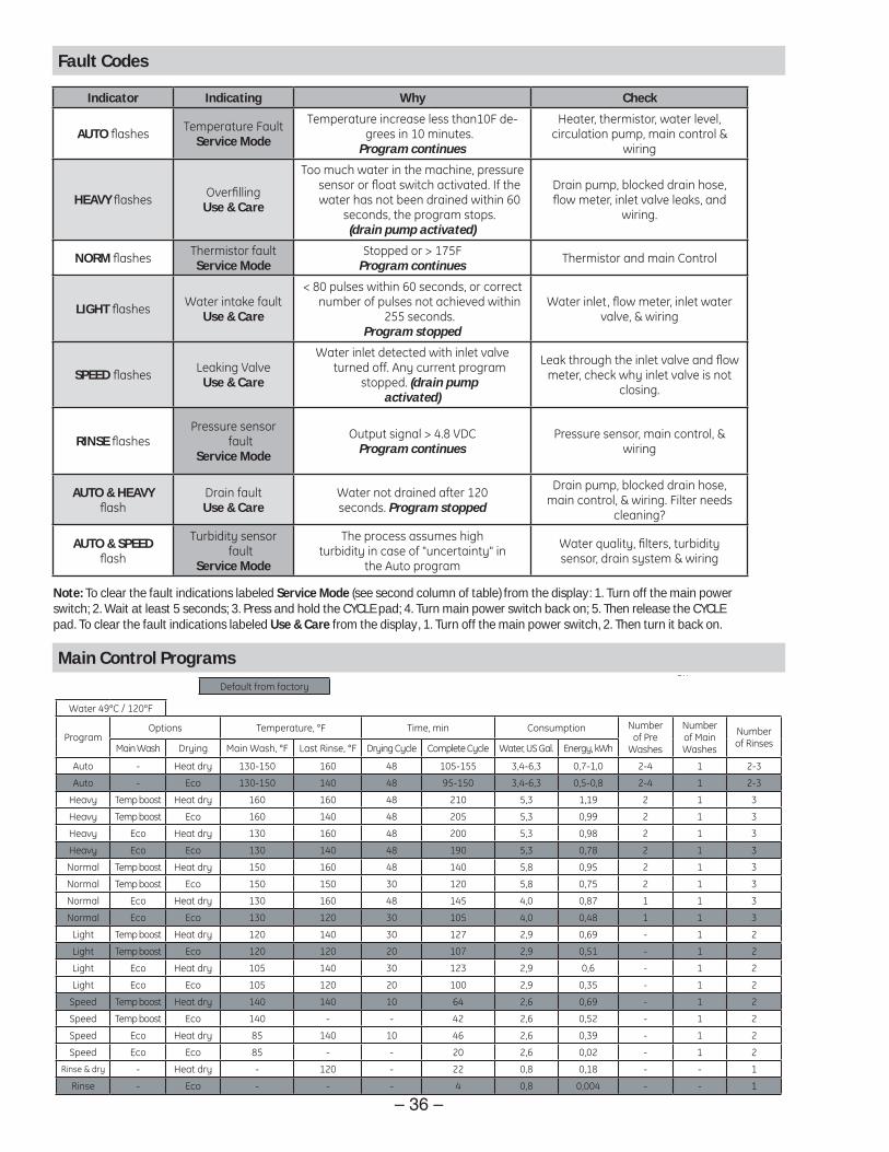
Auto - Heat dry 130-150 160 48 105-155 3,4-6,3 0,7-1,0 2-4 1 2-3
Auto - Eco 130-150 140 48 95-150 3,4-6,3 0,5-0,8 2-4 1 2-3
Heavy Temp boost Heat dry 160 160 48 210 5,3 1,19 2 1 3
Heavy Temp boost Eco 160 140 48 205 5,3 0,99 2 1 3
Heavy Eco Heat dry 130 160 48 200 5,3 0,98 2 1 3
Heavy Eco Eco 130 140 48 190 5,3 0,78 2 1 3
Normal Temp boost Heat dry 150 160 48 140 5,8 0,95 2 1 3
Normal Temp boost Eco 150 150 30 120 5,8 0,75 2 1 3
Normal Eco Heat dry 130 160 48 145 4,0 0,87 1 1 3
Normal Eco Eco 130 120 30 105 4,0 0,48 1 1 3
Light Temp boost Heat dry 120 140 30 127 2,9 0,69 - 1 2
Light Temp boost Eco 120 120 20 107 2,9 0,51 - 1 2
Light Eco Heat dry 105 140 30 123 2,9 0,6 - 1 2
Light Eco Eco 105 120 20 100 2,9 0,35 - 1 2
Speed Temp boost Heat dry 140 140 10 64 2,6 0,69 - 1 2
Speed Temp boost Eco 140 - - 42 2,6 0,52 - 1 2
Speed Eco Heat dry 85 140 10 46 2,6 0,39 - 1 2
Speed Eco Eco 85 - - 20 2,6 0,02 - 1 2
Rinse & dry - Heat dry - 120 - 22 0,8 0,18 - - 1
Rinse - Eco - - - 4 0,8 0,004 - - 1
De ault rom actorynce con rmed, program
Indicator Indicating Why Check
AUTO ashes Temperature FaultService Mode
Temperature increase less than10F de-grees in 10 minutes.
Program continues
Heater, thermistor, water level,circulation pump, main control &
wiring
HEAVY ashes Over llingUse & Care
Too much water in the machine, pressure sensor or oat switch activated. I the water has not been drained within 60
seconds, the program stops.(drain pump activated)
Drain pump, blocked drain hose,ow meter, inlet valve leaks, and
wiring.
NORM ashes Thermistor aultService Mode
Stopped or > 175FProgram continues Thermistor and main Control
LIGHT ashes Water intake aultUse & Care
< 80 pulses within 60 seconds, or correct number o pulses not achieved within
255 seconds.Program stopped
Water inlet, ow meter, inlet watervalve, & wiring
SPEED ashes Leaking ValveUse & Care
Water inlet detected with inlet valve turned o . Any current program
stopped. (drain pumpactivated)
Leak through the inlet valve and owmeter, check why inlet valve is not
closing.
RINSE ashesPressure sensor
aultService Mode
Output signal > 4.8 VDCProgram continues
Pressure sensor, main control, &wiring
AUTO & HEAVYash
Drain aultUse & Care
Water not drained a ter 120seconds. Program stopped
Drain pump, blocked drain hose,main control, & wiring. Filter needs
cleaning?
AUTO & SPEEDash
Turbidity sensor ault
Service Mode
The process assumes highturbidity in case o uncertainty in
the Auto program
Water uality, lters, turbiditysensor, drain system & wiring
Note: To clear the fault indications labeled Service Mode (see second column of table) from the display: 1. Turn off the main power switch; 2. Wait at least 5 seconds; 3. Press and hold the CYCLE pad; 4. Turn main power switch back on; 5. Then release the CYCLE pad. To clear the fault indications labeled Use & Care from the display, 1. Turn off the main power switch, 2. Then turn it back on.
Fault Codes
Main Control Programs

– 37 –
Troubleshooting Checklist
The troubleshooting checklist is common for all dishwasher models. They use different parts to accomplish the same thing and diagnosis will remain similar.
When a problem arises, and a possible cause is listed, follow the test and remove or replace procedures as outlined in this Technical Service Manual.
The wiring diagram, schematic, and service mode test are a necessity when making electrical checks. In most cases, an ohmmeter will handle all the tests necessary.
To verify the setup of any particular cycle of operation, refer to Control Panel Features.
Symptom Check for the Following Remedy Dishwasher will not operate when turned ON.
1. A blown fuse or tripped circuit breaker.
1. Replace the fuse or reset the breaker.
2. Damaged or defective wiring. 2. Repair the wiring.
3. Improper motor resistances. 3. Replace the motor.
4. Defective door switch contacts.
4. Replace the door switch.
5. Defective door latch. 5. Replace the door latch.
Dishwasher runs but will not heat.
1. Heater element is open. 1. Replace the heater element.
2. Damaged or defective wiring. 2. Repair the wiring.
Dishwasher runs but will not stop.
1. Electronic control inoperative. 1. Replace the electronic control.
2. Damaged or defective wiring. 2. Repair the wiring.
Dishwasher runs with door open.
1. Defective door safety switch. 1. Replace the door safety switch.
Motor hums but will not start or run.
1. Defective motor bearings. 1. Replace the motor.
2. Defective motor capacitor. 2. Replace the motor capacitor.
Motor trips out on internal thermal overload protector.
1. Improper motor voltage. 1. Replace the motor.
2. Motor shaft binding. 2. Replace the motor.
3. Motor windings shorted. 3. Replace the motor.
Etching on glassware.
1. Soft water condition (Natural or artifi cial).
1. Have a sample of the water analyzed by the local water department.
Dishwasher continues to fi ll even though there is no voltage to the fi ll valve (fl ooding condition).
1. Defective water fi ll valve. 1. Replace the water fi ll valve.2. Debris buildup under the diaphragm in the water fi ll valve.
2. Clean out the debris or replace the water fi ll valve.
(Continued next page)

– 38 –
Symptom Check for the Following RemedyNo heat during the dry cycle.
1. Defective heater element. 1. Replace the heater element.2. Damaged or defective wiring. 2. Repair the wiring.
Dishwasher will not fi ll with water or will not fi ll properly.
1. The water supply is turned off.
1. Turn the water supply on.
2. Low water pressure. 2. Minimum water pressure of 20 PSI.
3. Defective water fi ll valve. 3. Replace the water fi ll valve.4. Obstructed water fi ll valve or hose.
4. Disassemble and clean the water fi ll valve and hose.
5. Damaged or defective wiring. 5. Repair the wiring.6. Defective pressure switch. 6. Replace the pressure switch.7. Heavy water usage elsewhere in home.
7. Use dishwasher when water usage is at a minimum.
Dishwasher will not pump out.
1. Defective drain pump. 1. Replace the drain pump.2. Defective impeller. 2. Replace the impeller.3. Defective electronic control. 3. Replace the electronic
control.Water siphons out.
1. Drain hose loop too low. 1. Move the drain hose to the proper height.
2. Drain line connected to a fl oor drain not properly vented.
2. Install a vent air gap at counter top.
Too much water fi ll.
1. Defective water fi ll valve. 1. Replace the water fi ll valve.
Water leaks from dishwasher.
1. Too much water fi ll. 1. See previous symptom.2. Defective tub seal. 2. Replace the tub seal.3. Defective vent plate. 3. Replace the vent plate.4. Dishwasher door not level. 4. Adjust the dishwasher door.5. Dishwasher not level. 5. Level the dishwasher.6. Soap suds leak from dishwasher.
6. Refer to use and care manual.
7. Loose hose clamps. 7. Tighten or replace hose clamps.
8. Loose heater element. 8. Tighten heater element mounting nuts.
9. Defective water seals. 9. Replace the water seals.10. Motor and pump assembly not seated properly in tub liner bottom.
10. Remount the motor and pump assembly in the tub liner bottom.
(Continued next page)

– 39 –
Symptom Check for the Following RemedyPoor washability. 1. Improper loading of dishes,
pots, pans, and nesting of silverware.
1. Instruct the customer on proper loading of the dishwasher. Refer to the Owner's Manual.
2. Defective spray arm. 2. Check spray arm for proper rotation.
3. Water level should cover heating element.
3. See “Dishwasher will not fi ll with water or will not fi ll properly” symptom.
4. Defective detergent/rinse module.
4. Replace the detergent/rinse module.
5. Old, improper amount, or wrong type of detergent used (detergents lose effectiveness in a damp area).
5. Instruct the customer on proper use of dishwasher detergent. Refer to the Owner's Manual.
6. Low incoming water temperature.
6. Incoming water temperature of 120°F is required to properly dissolve dishwashing detergents.
7. Clogged fi lter assembly. 7. Clean the fi lter assembly and microfi lter.
Poor drying of dishes.
1. Improper loading of dishes, pots, pans, and nesting of silverware.
1. Instruct the customer on proper loading of the dishwasher. Refer to the Owner's Manual.
2. Low incoming water temperature.
2. Incoming water temperature of 120°F is required to properly dissolve dishwashing detergents.
3. Water remaining in tub after drain cycle is completed.
3. See “Dishwasher will not pump out” symptom.
4. Defective heating element. 4. Replace the heating element.
5. Damaged or defective wiring.
5. Repair the wiring.
Door will not latch.
1. Defective door latch. 1. Replace the door latch.
Noisy pump assembly.
1. Defective motor bearings. 1. Replace the pump motor.
2. A sucking sound is heard at the end of the cycle.
2. This is a normal condition.
Detergent left in the dispenser.
1. Detergent allowed to stand too long in the dispenser.
1. Instruct the customer on proper use of dishwasher detergent. Refer to the Owner's Manual.
2. Dispenser was wet when detergent was added.
2. Instruct the customer on proper use of dishwasher detergent. Refer to the Owner's Manual.
3. Detergent is binding on detergent/rinse module cover.
3. Replace the heating element.
4. Detergent cup held closed or blocked by large dishes.
4. Instruct the customer on proper loading of dishwasher. Refer to the Owner's Manual.
cycle is completed.
(Continued next page)

– 40 –
Symptom Check for the Following RemedyNoisy pump assembly.
1. Debris in bottom of tub sump area.
1. Clean out the sump area.
2. Pump parts were not properly installed.
2. Inspect the pump and correct any installation errors.
3. Impellers are not properly shimmed or are rubbing.
3. Use the shim gage furnished in the impeller seal kit. When the seal is properly shimmed the impellers will be in the correct operating position.
4. Defective motor bearings. 4. Replace the motor.5. A sucking sound is heard at the end of the cycle.
5. This is a normal condition.
Spotting or fi lming on glasses (reposition of food soil).
1. Detergent allowed to stand too long in the dispenser or excessive amounts of detergent are being used.
1. Instruct the customer on proper use of dishwasher detergent. Refer to the Owner's Manual.
2. Low incoming water temperature.
2. Incoming water temperature of 120°F is required to properly dissolve dishwashing detergents.
3. Improper loading of dishes, pots, pans, and nesting of silverware.
3. Instruct the customer on proper loading of the dishwasher. Refer to the Owner's Manual.
4. Water high in mineral content. 4. Have water analyzed. Use of commercially available rinse agents (such as Jet Dry) helps to reduce the spotting by lowering the surface tension of the water (the water then “sheets” off the dishes).
5. High incoming water temperature.
5. Incoming water temperature of 160°F or higher will cause high protein food particles to bake onto the dishes before detergent can remove them. Set water heater tank to deliver 120°F water.
6. Improper installation of the dishwasher to a food waste disposal.
6. Install properly. Refer to Installation Manual.

– 41 –
Washability Complaints
Hot Water – Ample supply of water at a temperature of 120°F is necessary for best results. Do not use dishwasher soon after using clothes washer or fi lling bathtub.
Loading - Consult Owner’s Manual on loading procedures.
Amount of Water – Make sure dishwasher is level. Check water level, allowing dishwasher to fi ll normally for fi rst fi ll. The water level should be to the heating coil. If water level is low, check for clogged screen and check pressure switch. (See Water Valve.)
Detergent/Rinse Module Leakage – Some moisture in cup is normal. Detergent must not be soaking wet, oozing out, and down the inner door panel. If a leak is detected, check the detergent/rinse module door lid, latch operation, and gasket seal. (See Detergent/Rinse Module.)
Proper Amount of Detergent – Use full detergent cup of fresh detergent in hard water. Use only enough detergent to get good wash performance in soft water.
Rinse Agent – Use rinse agent if spotting or drying is a problem. A rinse agent will improve the water sheeting action and drying performance.
Water Valve – (See Water Valve.)
Upper Basket – If a wash problem is reported for the upper basket, check for a leaking fl apper on the two ports built into the upper shower support. (See Upper Basket.)
Spray Arm – Check to be sure the spray arms spin freely and jets are not clogged. Check to be sure the middle spray arm water conduit is connecting properly to the main conduit.
Drying – Water inlet temperature must be at least 120°F for proper drying. Low water inlet temperature will prevent proper convection air movement and increase drying time substantially.
Compartment Lid
Rinse Agent Cap
Latch
Detergent Compartment

– 42 –
Schematic
WARNING: Power must be disconnected before servicing the appliance.
Note: Schematic diagram subject to change. Please refer to diagram supplied with product located behind the kick plate.
DR
AIN
PU
MP
FAN
FILTER
WA
TER
VA
LVE
WA
X
ON
/ OFF
SW
ITCH
DISPEN
SERSO
LENO
ID
RIN
SE
AID
SE
NS
OR DO
OR
INTE
RLO
CK
S
WITC
H
PR
ES
SU
RE
SE
NS
OR
TUR
BID
ITY S
EN
SO
R
LIGH
TS
WITC
H FLOW
ME
TER
LN
HA
LOG
EN
LAM
P
1 2
HE
ATIN
GE
LEM
EN
T
10
SG
EL
TB
FLOA
TS
WITC
H
NTC
THE
RM
ISTO
R
AP
VM
G
12
34
56
78
9LB
KD
FLS
VVA
XC
PIV
CIR
CU
LATION
PUM
P
MV
DIV
BE
GS
TSFM
1/C3/N
O
2/NC
M
M
M
70K Ω
@ 70°F
12 Ω 1200W
32 Ω
0.95K Ω
0.18K Ω 1.03K
Ω
<10K Ω
5W 12V
DC
25 Ω
1M Ω
MO
TOR
FAN
300 Ω
BBB
B
B
BB
BB
BB
BB
BB
CC
CC
CC
CC
CC
BC
CC
CC
CC
CC
C
CC
1/C
4/NO
W
BB
Black
Wire C
olor Code
BCWB
rown
White
OP
EN
S AT 444°F
RE
SE
TAB
LE TC
O
ON
E-TIM
E FU
SE
OP
EN
S AT 208°F

– 43 –
Warranty
YOUR MONOGRAM DISHWASHER WARRANTYStaple sales slip or cancelled check here. Proof of original purchase date is needed to obtain service under warranty.
WHAT IS COVEREDFrom the Date of the Original Purchase
ONE-YEAR Any part of the dishwasher which fails due to a defect in materials or workmanship. During this limited one-year warranty, GE will also provide, free of charge, all labor and in-home service to replace the defective part.
Five YearsThe dishwasher rack and/or the electronic control module, if these should fail due to a defect in materials or workmanship. During this five-year limited warranty, you will be responsible for any labor or in-home service costs.
LifetimeThe stainless steel tub or door liner, if it fails to contain water due to a defect in materials or workmanship. During this limited lifetime warranty, GE will also provide, free of charge, all labor and in-home service to replace the defective part.
This warranty is extended to the original purchaser and any succeeding owner for the products purchased for ordinary home use in the 48 mainland states, Hawaii or Washington, D.C. If the product is located in an area where service by a GE Authori ed Servicer is not available, you may be responsible for a trip charge or you may be required to bring the product to an Authori ed GE Service location for service. In Alaska the warranty is the same except that it is LIMITED because you must pay to ship the product to the service shop or for the service technician’s travel cost to your home.
All warranty service will be provided by our Factory Service Centers or by our authori ed Customer Care® servicers during normal working hours.
Should your appliance need service, during warranty period or beyond, call 800.444.1845. Please have serial number and model number available when calling for service.
WHAT IS NOT COVERED
Service trips to your home to teach you how to use the product.
Improper installation, delivery or maintenance. Replacement of house fuses or resetting of circuit breakers.
Failure of the product if it is abused, misused, or used for other than the intended purpose or used commercially.
Damage to the product caused by accident, fire, floods or acts of God.
Incidental or consequential damage caused by
possible defects with this appliance. Cleaning or servicing of the air gap device in the drain line.
Damage caused after delivery, including damage from items dropped on the door.
Product not accessible to provide required service.
Some states do not allow the exclusion or limitation of incidental or consequential damages, so the above limitation or exclusion may not apply to you. This warranty gives you specific legal rights, and you may also have other rights which vary from state to state. To know what your legal rights are in your state, consult your local or state consumer affairs office or your state’s Attorney General.
Warrantor: General Electric Company, Louisville, KY 40225
E CLUSION OF IMPLIED WARRANTIES Your sole and exclusive remedy is product repair as provided in this Limited Warranty. Any implied warranties, including the implied warranties of merchantability or fitness for a particular purpose, are limited to one year or the shortest period allowed by law.