30XA 252-1702 - mandilasng.com Advance product data.pdfAir-Cooled Liquid Chillers High Outdoor...
24
Air-Cooled Liquid Chillers High Outdoor Temperature Version 30XA 252-1702 Nominal cooling capacity 260-1700 kW The Aquaforce liquid chillers are the premium solution for industrial and commercial applications where installers, consultants and building owners require optimal performances and maximum quality. The Aquaforce liquid chillers are designed to meet current and future requirements in terms of energy efficiency, operating sound levels and reliability. They use the best technologies available today: - Twin-rotor screw compressors with a variable capacity valve. - R134a refrigerant with zero ozone depletion potential. - Low-noise generation IV Flying Bird fans made of composite material. - Aluminium micro-channel heat exchangers (MCHX) or copper/aluminium coils. - Touch-screen Pro-Dialog control system. The high outdoor temperature version has been specially designed to assure reliable and durable operation in areas with extreme climatic conditions: high outdoor temperature, sand storms etc. Features and advantages Very economical operation ■ Extremely high full load and part load energy efficiency: - Average COP of 3.15 kW/kW at nominal conditions - Average integrated part load value (IPLV) of 4.20 kW/kW (high-efficiency option) - New twin-rotor screw compressor equipped with a high- efficiency motor and a variable capacity valve that permits exact matching of the cooling capacity to the load. - All aluminium heat exchanger with micro-channels that is more efficient than a copper/aluminium coil. - Flooded multi-pipe evaporator. - Electronic expansion device permitting operation at a lower condensing pressure and improved utilisation of the evaporator heat exchange surface (superheat control). - Economizer system with electronic expansion device for increased cooling capacity. Low operating sound levels ■ Compressors - Discharge dampers integrated in the oil separator (Carrier patent). - Suction piping with flexible connections to prevent noise and vibration transmission. - Acoustic compressor and oil separator enclosure reducing radiated noise. ADVANCE PRODUCT DATA
Transcript of 30XA 252-1702 - mandilasng.com Advance product data.pdfAir-Cooled Liquid Chillers High Outdoor...

Air-Cooled Liquid ChillersHigh Outdoor Temperature Version
30XA 252-1702Nominal cooling capacity 260-1700 kW
The Aquaforce liquid chillers are the premium solution forindustrial and commercial applications where installers,consultants and building owners require optimalperformances and maximum quality.
The Aquaforce liquid chillers are designed to meet currentand future requirements in terms of energy efficiency,operating sound levels and reliability. They use the besttechnologies available today:- Twin-rotor screw compressors with a variable capacity
valve.- R134a refrigerant with zero ozone depletion potential.- Low-noise generation IV Flying Bird fans made of
composite material.- Aluminium micro-channel heat exchangers (MCHX) or
copper/aluminium coils.- Touch-screen Pro-Dialog control system.
The high outdoor temperature version has been speciallydesigned to assure reliable and durable operation in areaswith extreme climatic conditions: high outdoor temperature,sand storms etc.
Features and advantages
Very economical operation■ Extremely high full load and part load energy efficiency:
- Average COP of 3.15 kW/kW at nominal conditions- Average integrated part load value (IPLV) of 4.20 kW/kW
(high-efficiency option)- New twin-rotor screw compressor equipped with a high-
efficiency motor and a variable capacity valve that permitsexact matching of the cooling capacity to the load.
- All aluminium heat exchanger with micro-channels that ismore efficient than a copper/aluminium coil.
- Flooded multi-pipe evaporator.- Electronic expansion device permitting operation at a lower
condensing pressure and improved utilisation of theevaporator heat exchange surface (superheat control).
- Economizer system with electronic expansion device forincreased cooling capacity.
Low operating sound levels■ Compressors
- Discharge dampers integrated in the oil separator (Carrierpatent).
- Suction piping with flexible connections to prevent noiseand vibration transmission.
- Acoustic compressor and oil separator enclosure reducingradiated noise.
ADVANCE PRODUCT DATA

■ Condenser section- Condenser coils in V-shape with an open angle, allowing
quieter air flow across the coil- Low-noise 4th generation Flying Bird fans, made of a
composite material (Carrier patent) are now even quieterand do not generate intrusive low-frequency noise
- Rigid fan mounting preventing start-up noise (Carrierpatent)
Easy and fast installation■ Integrated hydronic module (option)
- Centrifugal low or high-pressure water pump (as required),based on the pressure loss of the hydronic installation
- Single or dual pump (as required) with operating timebalancing and automatic changeover to the back-up pump ifa fault develops
- Water filter protecting the water pump against circulatingdebris
- High-capacity membrane expansion tank ensurespressurisation of the water circuit
- Thermal insulation and aluminium protection- Pressure gauge to check filter pollution and measure the
system water flow rate- Water flow control valve
■ Simplified electrical connections- Main disconnect switch with high trip capacity- Safe 24 V control circuit
■ Fast commissioning- Systematic factory operation test before shipment- Quick-test function for step-by-step verification of the
instruments, expansion devices, fans and compressors
Environmental care■ R134a refrigerant
- Refrigerant of the HFC group with zero ozone depletionpotential
- 30% reduction in the refrigerant charge through the use ofmicro-channel heat exchangers
■ Leak-tight refrigerant circuit- Reduction of leaks as no capillary tubes and flare
connections are used- Verification of pressure transducers and temperature
sensors without transferring refrigerant charge- Discharge shut-off valve and liquid line service valve for
simplified maintenance.
Absolute reliability■ Screw compressors
- Industrial-type screw compressors with oversized bearingsand motor cooled by suction gas.
- All compressor components are easily accessible on siteminimising down-time.
- Electronic motor protection against overloads and powersupply faults (loss of phase, phase reversal).
■ Air-cooled condenser- The all aluminium micro-channel heat exchanger (MCHX)
is not very sensitive to fouling by sand and offers acorrosion resistance that is 3.5 times higher than that oftraditional coils or coils with copper tubes and aluminiumfins without slots.
■ Evaporator- Thermal insulation with aluminium sheet finish for perfect
resistance against outside aggression (solar radiation,birds).
■ Auto-adaptive control- Control algorithm prevents excessive compressor cycling
(Carrier patent)- New compressor unloading algorithm (Carrier patent). If
the condensing pressure is abnormally high, e.g. a fouledcondenser coil, excessive outside temperature etc., theAquaforce automatically adjusts the maximum coolingcapacity and continues to operate at limited capacity.
■ Control box with reinforced air tightness- Reinforced air tightness to protect against sand penetration
(protection level IP54)- Forced ventilation to prevent overheating of the electrical
components.■ Exceptional endurance tests
- Partnerships with specialised laboratories and use of limitsimulation tools (finite element calculation) for the designof critical components.
- Transport simulation test in the laboratory on a vibratingtable. The test is based on a military standard andequivalent to 4000 km by truck.
- Salt mist corrosion resistance test in the laboratory forincreased corrosion resistance.
Pro-Dialog controlPro-Dialog combines intelligence with operating simplicity.The control constantly monitors all machine parameters andprecisely manages the operation of compressors, electronicexpansion devices, fans and of the evaporator water pump foroptimum energy efficiency.
■ Energy management- Internal time schedule clock: controls chiller on/off times
and operation at a second set-point- Set-point reset based on the outside air temperature or the
return water temperature- Master/slave control of two chillers connected in series or
in parallel with operating time equalisation and automaticchange-over in case of a unit fault.
■ Ease-of-use- User interface with large touch screen (120 x 99 mm) for
intuitive access to the operating parameters. Theinformation is in clear text and can be displayed in locallanguage (please contact your distributor).
Remote management (standard)Aquaforce is equipped with an RS485 serial port that offersmultiple remote control, monitoring and diagnosticpossibilities. Carrier offers a vast choice of control products,specially designed to control, manage and supervise theoperation of an air conditioning system. Please consult yourCarrier representative for more information.
Aquaforce also communicates with other buildingmanagement systems via optional communication gateways.A connection terminal allows remote control of theAquaforce by wired cable:- Start/stop: opening of this contact will shut down the unit- Dual set-point: closing of this contact activates a second
set-point (example: unoccupied mode)- Demand limit: closing of this contact limits the maximum
chiller capacity to a predefined value- Heat reclaim (option): closing of this contact allows heat
reclaim mode operation- Water pump 1 and 2 control*: these outputs control the
contactors of one or two evaporator water pumps- Water pump on reversal*: these contacts are used to detect
a water pump operation fault and automatically change overto the other pump
- Operation indication: this volt-free contact indicates thatthe chiller is operating (cooling load) or that it is ready tooperate (no cooling load)
- Alert indication: this volt-free contact indicates the need tocarry out a maintenance operation or the presence of aminor fault
- Alarm indication: this volt-free contact indicates thepresence of a major fault that has led to the shut-down ofone or two refrigerant circuits
* not available for units with the hydronic module option
2

Remote management (EMM option)The Energy Management Module offers extended remotecontrol possibilities:- Room temperature: permits set-point reset based on the
building indoor air temperature (with Carrier thermostat)- Set point reset: ensures reset of the cooling set-point based
on a 4-20 mA or 0-5 V signal- Demand limit: permits limitation of the maximum chiller
power or current based on a 0-10 V signal- Demand limit 1 and 2: closing of these contacts limits the
maximum chiller power or current to two predefined values- User safety: this contact can be used for any customer
safety loop; opening of the contact generates a specificalarm
- Ice storage end: when ice storage has finished, this inputpermits return to the second set-point (unoccupied mode)
- Compressor operation: indicates the operation of thecompressors in refrigerant circuits A, B and C
- Time schedule override: closing of this contact cancels thetime schedule effects
- Out of service: this signal indicates that the chiller iscompletely out of service
- Chiller capacity: this analogue output (0-10 V) gives animmediate indication of the chiller capacity
New generation screw compressorThe new generation of the Carrier 06T screw compressorsbenefits from Carrier’s long experience in the development oftwin-rotor screw compressors. The compressor is equippedwith bearings with oversized rollers, oil pressure lubricatedfor reliable and durable operation, even at maximum load.A variable control valve controlled by the oil pressurepermits infinitely variable cooling capacity. This systemallows optimal adjustment of the compressor coolingcapacity and ensures exceptionally high stability of thechilled water leaving temperature.
Another advantage: if a fault occurs e.g. if the condenser isfouled or at very high outside temperature, the compressordoes not switch off, but continues operation with a reducedcapacity.
The compressor is equipped with a separate oil separator thatminimises the amount of oil in circulation in the refrigerantcircuit and considerably reduces discharge gas pulsations formuch quieter operation.
3
06T screw compressor

4
All aluminium micro-channel heat exchanger (MCHX)Already utilised in the automobile and aeronautical industriesfor many years, the MCHX used in the Aquaforce is entirelymade of aluminium. This one-piece concept significantlyincreases its corrosion resistance by eliminating the galvaniccurrents that are created when two different metals (copperand aluminium) come into contact in a saline or corrosiveatmosphere.
The MCHX heat exchanger is approximately 10% moreefficient than a traditional coil and allows a 30% reduction inthe amount of refrigerant used in the chiller. The lowthickness of the MCHX reduces air pressure losses by 50%and makes it less susceptible to fouling by sand than atraditional coil. Cleaning of the MCHX heat exchanger isvery fast using a high-pressure washer.
All aluminium micro-channel heat exchanger
Pro-Dialog operator interface with touch-screen

5
Hydronic module (option)
1 2
Legend
Components of unit and hydronic module1 Victaulic screen filter2 Expansion tank3 Safety valve4 Available pressure pump5 Pressure tap valve (see Installation Manual)6 Pressure gauge to measure the component pressure loss (see Installation Manual)7 System vent valve, pressure gauge8 Drain valve9 Water flow control valve10 Evaporator11 Evaporator defrost heater (option)12 Hydronic module defrost heater13 Air vent (evaporator)14 Water purge (evaporator)15 Expansion compensator (flexible connections)16 Flow switch17 Water temperature sensor
System components18 Air vent19 Flexible connection20 Shut-down valves21 Charge valve
--- Hydronic module
Typical hydronic circuit diagram

6
Options and accessoriesOptions No. Description Advantages Use
Grilles 23 Metallic grilles on all four unit faces Improved aesthetics 30XA 252-1702
Electronic starter 25 Electronic starter on each compressor Reduced start-up current 30XA 252-1702
Suction valve 92 Shut-off valves on the compressor suction piping Simplified maintenance 30XA 252-702
Unit without enclosure 253 Compressors not equipped with acoustic enclosure More economical 30XA 252-1702
Energy Management 156 See chapter “Energy Management Module” Easy connection by wired connection 30XA 252-1702Module EMM to a building management system
One-pass evaporator 100C Evaporator with one pass water-side Reduced water inlet and outlet pressure 30XA 252-1002losses on opposite sides
Three-pass evaporator 100A Evaporator with three passes water-side Increased water inlet and outlet pressure losses 30XA 252-602on opposite sides
Reversed water connections 107 Evaporator with reversed water inlet/outlet Simplification of the water piping 30XA 252-1702
Low water temperature version 5 Leaving water temperature down to -10°C Ice storage/industrial process application 30XA 252-1702
Low-pressure single-pump 116F See hydronic module chapter Easy and fast installation 30XA 252-502hydronic module
Low-pressure dual-pump 116G See hydronic module chapter Easy and fast installation, operating safety 30XA 252-502hydronic module
High-pressure single-pump 116B See hydronic module chapter Easy and fast installation 30XA 252-502hydronic module
High-pressure dual-pump 116C See hydronic module chapter Easy and fast installation, operating safety 30XA 252-502hydronic module
Corrosion protection, 2B Factory application of Blygold Polual treatment Improved corrosion resistance, recommended 30XA 252-1702traditional coils on the copper/aluminium coils for urban, industrial and rural environments option 254
Corrosion protection, 3A Fins made of pre-treated aluminium Improved corrosion resistance, recommended 30XA 252-1702traditional coils (polyurethane and epoxy) for marine environments option 254
Evaporator frost protection 41A Resistance heater on the evaporator Evaporator frost protection down to -25°C 30XA 252-1702outside temperature
Evaporator and hydronic 41B Resistance heater on the evaporator and Evaporator and hydronic module frost 30XA 252-502module frost protection the hydronic module protection down to -25°C outside temperature
JBus gateway 148B Two-directional communications board, Easy connection by communication bus 30XA 252-1702complies with JBus protocol to a building management system
BacNet gateway 148C Two-directional communications board, Easy connection by communication bus 30XA 252-1702complies with BacNet protocol to a building management system
LON gateway 148D Two-directional communications board, Easy connection by communication bus 30XA 252-1702complies with LON protocol to a building management system
7
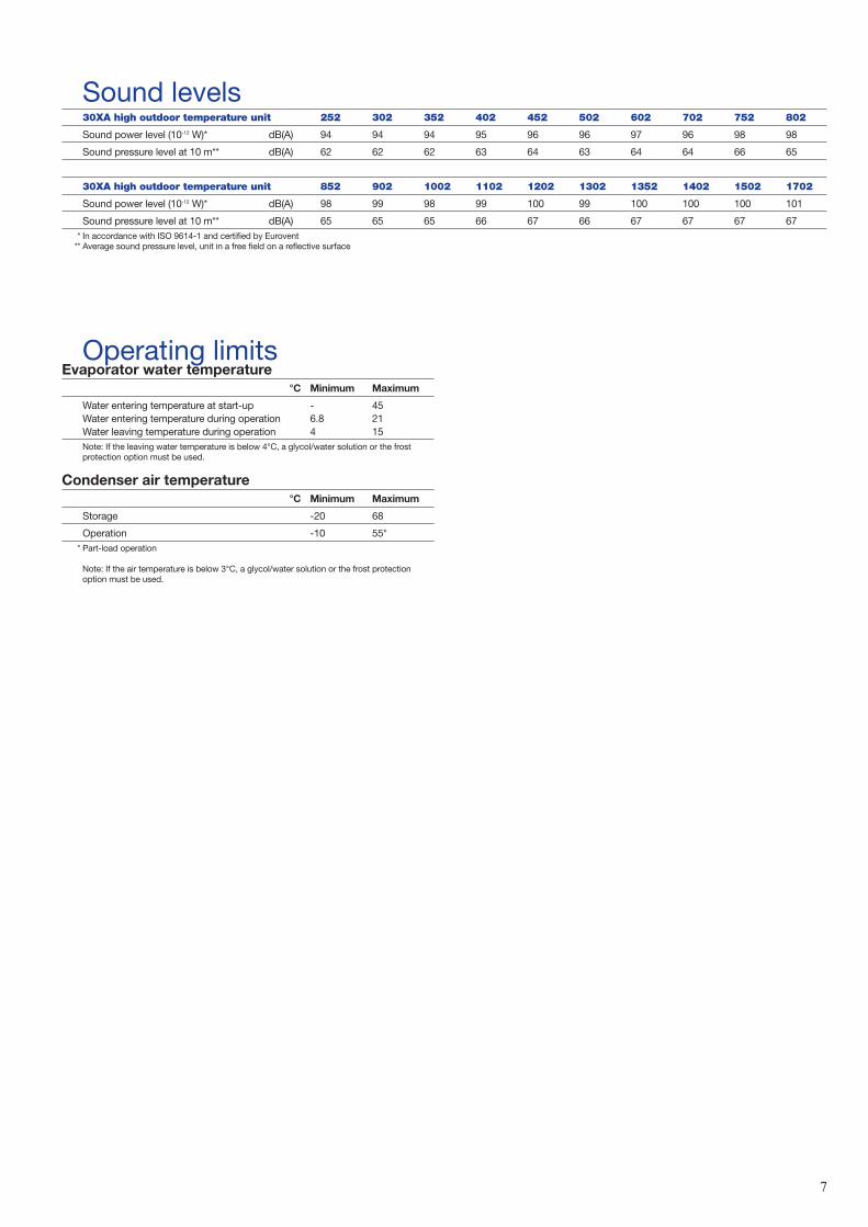
Sound levels30XA high outdoor temperature unit 252 302 352 402 452 502 602 702 752 802
Sound power level (10-12 W)* dB(A) 94 94 94 95 96 96 97 96 98 98
Sound pressure level at 10 m** dB(A) 62 62 62 63 64 63 64 64 66 65
30XA high outdoor temperature unit 852 902 1002 1102 1202 1302 1352 1402 1502 1702
Sound power level (10-12 W)* dB(A) 98 99 98 99 100 99 100 100 100 101
Sound pressure level at 10 m** dB(A) 65 65 65 66 67 66 67 67 67 67* In accordance with ISO 9614-1 and certified by Eurovent
** Average sound pressure level, unit in a free field on a reflective surface
Operating limitsEvaporator water temperature
°C Minimum Maximum
Water entering temperature at start-up - 45Water entering temperature during operation 6.8 21Water leaving temperature during operation 4 15Note: If the leaving water temperature is below 4°C, a glycol/water solution or the frostprotection option must be used.
Condenser air temperature°C Minimum Maximum
Storage -20 68
Operation -10 55** Part-load operation
Note: If the air temperature is below 3°C, a glycol/water solution or the frost protectionoption must be used.

8
Physical data30XA 252 302 352 402 452 502 602 702 752 802
Nominal cooling capacity* kWUnit with MCHX heat exchanger 260 283 303 384 439 493 597 655 697 750Unit with copper/aluminium coils 264 289 314 389 447 503 613 673 717 780
Operating weight** kgUnit with MCHX heat exchanger 3551 3597 3632 4454 4524 4992 5868 6022 6304 6601Unit with copper/aluminium coils (option 254) 3871 3903 4427 4865 4931 5499 6474 6641 7402 7716Unit with copper/aluminium coils (option 255) 4272 4304 4848 5347 5413 6010 7081 7268 8079 8393
Refrigerant R134aCircuit A (MCHX heat exchanger) kg 36 37 37 53 54 63 62 62 70 70Circuit B (MCHX heat exchanger) kg 38 38 39 37 39 39 62 66 62 62Circuit A (copper/aluminium coil, option 254) kg 60 55 70 85 85 102 102 102 110 112Circuit B (copper/aluminium coil, option 254) kg 64 56 56 56 56 56 88 105 88 98Circuit A (copper/aluminium coil, option 255) kg 60 55 70 85 85 102 102 102 132 134Circuit B (copper/aluminium coil, option 255) kg 77 67 67 67 67 67 106 126 106 118
Compressors 06T semi-hermetic screw compressors, 50 r/sCircuit A 1 1 1 1 1 1 1 1 1 1Circuit B 1 1 1 1 1 1 1 1 1 1Minimum capacity % 15 14 15 11 11 10 14 15 11 13
Control PRO-DIALOG, electronic expansion valve (EXV)
Condensers Aluminium micro-channel heat exchangerFans Flying Bird IVQuantityUnit with MCHX heat exchanger 6 6 6 8 8 9 11 12 12 12Unit with copper/aluminium coil 6 6 7 8 8 9 11 12 13 13
Evaporator Flooded multi-pipe typeWater content l 58 61 61 66 70 77 79 94 98 119Maximum operating pressure kPa 1000 1000 1000 1000 1000 1000 1000 1000 1000 1000
Water connections VictaulicDiameter in 5 5 5 5 5 5 5 6 6 6Outside diameter mm 141.3 141.3 141.3 141.3 141.3 141.3 141.3 168.3 168.3 168.3
30XA 852 902 1002 1102 1202 1302 1352 1402 1502 1702
Nominal cooling capacity* kWUnit with MCHX heat exchanger 804 854 956 1059 1156 1245 1314 1379 1427 1604Unit with copper/aluminium coils 828 884 989 1089 1191 1292 1368 1420 1474 1692
Operating weight** kgUnit with MCHX heat exchanger 7137 7419 8022 9847 10282 10665 10996 12011 12155 14279Unit with copper/aluminium coils, option 254 7842 8590 8836 10877 11294 11650 12018 13207 13365 15689Unit with copper/aluminium coils, option 255 8539 9307 9573 11849 12286 12642 13040 14299 14457 17083
Refrigerant R134aCircuit A (MCHX heat exchanger) kg 77 70 77 69 80 84 84 100 90 77Circuit B (MCHX heat exchanger) kg 66 75 84 66 66 68 71 85 85 66Circuit C (MCHX heat exchanger) kg - - - 97 97 97 93 97 97 77Circuit D (MCHX heat exchanger) kg - - - - - - - - - 66Circuit A (copper/aluminium coil, option 254) kg 120 110 130 102 112 110 110 130 130 120Circuit B (copper/aluminium coil, option 254) kg 98 110 125 96 96 96 105 110 125 98Circuit C (copper/aluminium coil, option 254) kg - - - 120 120 120 120 120 120 120Circuit D (copper/aluminium coil, option 254) kg - - - - - - - - - 98Circuit A (copper/aluminium coil, option 255) kg 144 132 156 122 134 132 132 156 156 144Circuit B (copper/aluminium coil, option 255) kg 118 132 150 115 115 115 126 132 150 118Circuit C (copper/aluminium coil, option 255) kg - - - 144 144 144 144 144 144 144Circuit D (copper/aluminium coil, option 255) kg - - - - - - - - - 118
Compressors 06T semi-hermetic screw compressors, 50 r/sCircuit A 1 1 1 1 1 1 1 1 1 1Circuit B 1 1 1 1 1 1 1 1 1 1Circuit C - - - 1 1 1 1 1 1 1Circuit D - - - - - - - - - 1Minimum capacity % 12 15 15 7 7 7 9 9 10 6
Control PRO-DIALOG, electronic expansion valve (EXV)
Condensers Aluminium micro-channel heat exchangerFans Flying Bird IVQuantityUnit with MCHX heat exchanger 14 14 16 19 20 20 20 24 24 28Unit with copper/aluminium coil 14 15 16 19 20 20 20 24 24 28
Evaporator Flooded multi-pipe typeWater content l 119 130 140 168 182 203 224 230 240 240Maximum operating pressure kPa 1000 1000 1000 1000 1000 1000 1000 1000 1000 1000
Water connections VictaulicDiameter in 6 6 8 6 6 6 6/8 6/8 6/8 6Outside diameter mm 168.3 168.3 219.1 168.3 168.3 168.3 168.3/ 168.3/ 168.3/ 168.3
219.1 219.1 219.1* Nominal conditions: evaporator entering/leaving water temperature = 12°C/7°C. Outdoor air temperature = 35°C, evaporator fouling factor = 0.000018 m2 K/W
** Weights are guidelines only.Note: Unit sizes 30XA 1402 to 1702 are supplied in two field-assembled modules.

9
Electrical data30XA (unit without hydronic module) 252 302 352 402 452 502 602 702 752 802
Power circuitNominal power supply V-ph-Hz 400-3-50Voltage range V 360-440
Maximum supply cable section mm2
Circuits A + B 1 x 240/ 1 x 240/ 1 x 240/ 2 x 240 2 x 240 2 x 240 3 x 240 3 x 240 4 x 240 4 x 2402 x 150 2 x 150 2 x 150
Short circuit holding current (rms) kACircuits A + B 38 38 38 38 38 38 50 50 50 50
High outdoor temperature unit
Maximum start-up current, circuits A + B* A 267 267 289 400 507 507 579 608 778 807Nominal start-up current, circuits A + B** A 247 247 264 380 482 482 539 562 738 761
Cosine Phi (maximum)* 0.88 0.88 0.89 0.88 0.88 0.89 0.88 0.89 0.88 0.88Cosine Phi (nominal)** 0.84 0.85 0.85 0.84 0.84 0.85 0.84 0.85 0.84 0.84
Maximum power input, circuits A + B* ‡ kW 118 132 148 166 189 208 251 270 304 321
Nominal unit current draw, circuits A + B** A 154 154 154 154 154 154 154 154 154 154
Full load unit current draw (Un), circuits A + B***‡ A 194 216 241 274 310 338 411 439 500 525
Maximum unit current draw (Un – 10%)****Circuits A + B A 216 240 268 304 345 376 457 488 556 583
Hydronic module (option)30XA 252 302 352 402 452 502
Single or dual low-pressure pumpMotor power kW 2.2 2.2 3 4 4 5.5Power input kW 2.8 2.8 3.9 5.1 5.1 7.2Maximum current draw A 4.7 4.7 6.4 8.2 8.2 11.7
Single or dual high-pressure pumpMotor power kW 4 5.5 5.5 7.5 11 11Power input kW 5.1 7.2 7.2 9.2 13.2 13.2Maximum current draw A 8.2 11.7 11.7 15 21.2 21.2
* At maximum operating conditions** At nominal operating conditions: air 35°C, water 12/7°C
*** Maximum current draw at nominal voltage**** Maximum current draw at nominal voltage – 10%
‡ Values given on the unit name plate

10
Electrical data30XA (unit without hydronic module) 852 902 1002 1102 1202 1302 1352 1402 1502 1702
Power circuitNominal power supply V-ph-Hz 400-3-50Voltage range V 360-440
Maximum supply cable section mm2
Circuits A + B 5 x 240 6 x 240 6 x 240 3 x 240 4 x 240 4 x 240 6 x 240 6 x 240 6 x 240 5 x 240Circuits C + D - - - 3 x 240 3 x 240 3 x 240 3 x 240 3 x 240 3 x 240 5 x 240
Short circuit holding current (rms) kACircuits A + B 50 50 50 50 50 50 50 50 50 50Circuits C + D - - - 50 50 50 50 50 50 50
High outdoor temperature unit
Maximum start-up current* ACircuits A + B 807 892 945 579 778 803 889 892 945 807Circuits C + D - - - 587 587 587 587 587 587 807
Nominal start-up current** ACircuits A + B 761 827 869 539 738 757 824 827 869 774Circuits C + D - - - 587 587 587 587 587 587 761
Cosine Phi (maximum)* 0.89 0.88 0.89 0.88 0.88 0.89 0.89 0.89 0.89 0.89Cosine Phi (nominal)** 0.85 0.84 0.85 0.88 0.88 0.88 0.88 0.87 0.88 0.85
Maximum power input* ‡ kWCircuits A + B 356 374 442 251 303 352 404 409 442 270Circuits C + D - - - 221 221 221 219 221 221 270
Nominal unit current draw** ACircuits A + B 154 154 154 154 154 154 154 154 154 154Circuits C + D - - - 282 282 282 278 282 282 456
Full load unit current draw (Un)***‡ ACircuits A + B 578 614 716 411 496 571 656 667 716 578Circuits C + D - - - 358 358 358 355 358 358 578
Maximum unit current draw (Un – 10%)****Circuits A + B 642 682 796 457 552 634 729 741 796 642Circuits C + D - - - 398 398 398 394 398 398 642
* At maximum operating conditions** At nominal operating conditions: air 35°C, water 12/7°C
*** Maximum current draw at nominal voltage**** Maximum current draw at nominal voltage – 10%
‡ Values given on the unit name plate
Note: Unit sizes 30XA 1102 to 1702 have two power connection points (circuits A + B and circuits C + D).

11
Dimensions/clearances30XA 252-302-352
Ø 1
41.3
Vict
aulic
type
75
Ø 1
41.3
Vict
aulic
type
75
Leg
end
:A
ll di
men
sion
s ar
e gi
ven
in m
m.
Req
uire
d cl
eara
nces
for
mai
nten
ance
and
air
flow
Rec
omm
ende
d sp
ace
for
evap
orat
or tu
be re
mov
al
Wat
er in
let
Wat
er o
utle
t
NO
TE: D
raw
ings
are
not
con
trac
tual
ly b
indi
ng.
Bef
ore
desi
gnin
g an
inst
alla
tion,
con
sult
the
cert
ified
dim
ensi
onal
dra
win
gs, a
vaila
ble
onre
ques
t.

Dimensions/clearances30XA 402-45230XA 352 with copper/aluminium coils (options 254/255)
5/8”
SA
E M
flar
e
Ø 1
41.3
Vict
aulic
type
75
12
Ø 1
41.3
Vict
aulic
type
75
Leg
end
:A
ll di
men
sion
s ar
e gi
ven
in m
m.
Req
uire
d cl
eara
nces
for
mai
nten
ance
and
air
flow
Rec
omm
ende
d sp
ace
for
evap
orat
or tu
be re
mov
al
Wat
er in
let
Wat
er o
utle
t
NO
TE: D
raw
ings
are
not
con
trac
tual
ly b
indi
ng.
Bef
ore
desi
gnin
g an
inst
alla
tion,
con
sult
the
cert
ified
dim
ensi
onal
dra
win
gs, a
vaila
ble
onre
ques
t.

13
Dimensions/clearances30XA 502
Ø 1
41.3
Vict
aulic
type
75
Ø 1
41.3
Vict
aulic
type
75 Le
gen
d:
All
dim
ensi
ons
are
give
n in
mm
.
Req
uire
d cl
eara
nces
for
mai
nten
ance
and
air
flow
Rec
omm
ende
d sp
ace
for
evap
orat
or tu
be re
mov
al
Wat
er in
let
Wat
er o
utle
t
NO
TE: D
raw
ings
are
not
con
trac
tual
ly b
indi
ng.
Bef
ore
desi
gnin
g an
inst
alla
tion,
con
sult
the
cert
ified
dim
ensi
onal
dra
win
gs, a
vaila
ble
onre
ques
t.

14
Dimensions/clearances30XA 602-702-752-802
Ø E
Vict
aulic
type
75
Ø F
Vict
aulic
type
75
30X
A602
702
752
802
A35
637
237
232
5
B27
224
224
228
4
C43
843
843
843
8
D28
5228
5228
5228
38
øE14
1.3
168.
316
8.3
168.
3
øF14
1.3
168.
316
8.3
168.
3
Leg
end
:A
ll di
men
sion
s ar
e gi
ven
in m
m.
Req
uire
d cl
eara
nces
for
mai
nten
ance
and
air
flow
Rec
omm
ende
d sp
ace
for
evap
orat
or tu
bere
mov
al
Wat
er in
let
Wat
er o
utle
t
NO
TE: D
raw
ings
are
not
con
trac
tual
ly b
indi
ng.
Bef
ore
desi
gnin
g an
inst
alla
tion,
con
sult
the
cert
ified
dim
ensi
onal
dra
win
gs, a
vaila
ble
onre
ques
t.
C
A B

15
Dimensions/clearances30XA 852-90230XA 752-802 with copper/aluminium coils (options 254/255)
Ø 1
68.3
Vict
aulic
type
75
Ø 1
68.3
Vict
aulic
type
75
Leg
end
:A
ll di
men
sion
s ar
e gi
ven
in m
m.
Req
uire
d cl
eara
nces
for
mai
nten
ance
and
air
flow
Rec
omm
ende
d sp
ace
for
evap
orat
or tu
be re
mov
al
Wat
er in
let
Wat
er o
utle
t
NO
TE: D
raw
ings
are
not
con
trac
tual
ly b
indi
ng.
Bef
ore
desi
gnin
g an
inst
alla
tion,
con
sult
the
cert
ified
dim
ensi
onal
dra
win
gs, a
vaila
ble
onre
ques
t.

16
Dimensions/clearances30XA 100230XA 902 with copper/aluminium coils (options 254/255)
5/8”
SA
E M
flar
e
Ø E
Vict
aulic
type
75
Ø F
Vict
aulic
type
75
Leg
end
:A
ll di
men
sion
s ar
e gi
ven
in m
m.
Req
uire
d cl
eara
nces
for
mai
nten
ance
and
air
flow
Wat
er in
let
Wat
er o
utle
t
NO
TE: D
raw
ings
are
not
con
trac
tual
ly b
indi
ng.
Bef
ore
desi
gnin
g an
inst
alla
tion,
con
sult
the
cert
ified
dim
ensi
onal
dra
win
gs, a
vaila
ble
onre
ques
t.
C
AB

17
Dimensions/clearances30XA 1102-1352
Leg
end
:A
ll di
men
sion
s ar
e gi
ven
in m
m.
Req
uire
d cl
eara
nces
for
mai
nten
ance
and
air
flow
Rec
omm
ende
d sp
ace
for
evap
orat
or tu
bere
mov
al
Wat
er in
let
Wat
er o
utle
t
NO
TE: D
raw
ings
are
not
con
trac
tual
ly b
indi
ng.
Bef
ore
desi
gnin
g an
inst
alla
tion,
con
sult
the
cert
ified
dim
ensi
onal
dra
win
gs, a
vaila
ble
onre
ques
t.
Vie
w F
Vie
w F
Ø H
D
C
B
A
Ø G

18
Dimensions/clearances30XA 1402-1502 – module 1/2
5/8”
SA
E M
flar
e
Ø 2
19.1
Vict
aulic
type
75
Ø 2
19.1
Vic
taul
ic ty
pe 7
5
Module 2
Leg
end
:A
ll di
men
sion
s ar
e gi
ven
in m
m.
Req
uire
d cl
eara
nces
for
mai
nten
ance
and
air
flow
Wat
er in
let
Wat
er o
utle
t
NO
TE: D
raw
ings
are
not
con
trac
tual
ly b
indi
ng.
Bef
ore
desi
gnin
g an
inst
alla
tion,
con
sult
the
cert
ified
dim
ensi
onal
dra
win
gs, a
vaila
ble
onre
ques
t.

19
Dimensions/clearances30XA 1402-1502 – module 2/2
Ø 1
68.3
Vict
aulic
type
75
5/8”
SA
E M
flar
e
Ø 1
68.3
Vict
aulic
type
75
Mod
ule
1
Leg
end
:A
ll di
men
sion
s ar
e gi
ven
in m
m.
Req
uire
d cl
eara
nces
for
mai
nten
ance
and
air
flow
Wat
er in
let
Wat
er o
utle
t
NO
TE: D
raw
ings
are
not
con
trac
tual
ly b
indi
ng.
Bef
ore
desi
gnin
g an
inst
alla
tion,
con
sult
the
cert
ified
dim
ensi
onal
dra
win
gs, a
vaila
ble
on re
ques
t.
Uni
t siz
es 1
402-
1502
are
sup
plie
d in
two
field
-as
sem
bled
mod
ules
(con
nect
ion
pipe
com
plet
ion
tobe
don
e by
the
inst
alle
r).

20
Dimensions/clearances30XA 1702 – module 1/2
Ø 1
68.3
Vic
taul
ic ty
pe 7
5Ø
168
.3 V
icta
ulic
type
75
Module 2
Leg
end
:A
ll di
men
sion
s ar
e gi
ven
in m
m.
Req
uire
d cl
eara
nces
for
mai
nten
ance
and
air
flow
Rec
omm
ende
d sp
ace
for
evap
orat
or tu
be re
mov
al
Wat
er in
let
Wat
er o
utle
t
NO
TE: D
raw
ings
are
not
con
trac
tual
ly b
indi
ng.
Bef
ore
desi
gnin
g an
inst
alla
tion,
con
sult
the
cert
ified
dim
ensi
onal
dra
win
gs, a
vaila
ble
onre
ques
t.

21
Dimensions/clearances30XA 1702 – module 2/2
Ø 1
68.3
Vic
taul
ic ty
peØ
168
.3 V
icta
ulic
type
Mod
ule
1
Leg
end
:A
ll di
men
sion
s ar
e gi
ven
in m
m.
Req
uire
d cl
eara
nces
for
mai
nten
ance
and
air
flow
Wat
er in
let
Wat
er o
utle
tN
OTE
: Dra
win
gs a
re n
ot c
ontr
actu
ally
bin
ding
. Bef
ore
desi
gnin
g an
inst
alla
tion,
con
sult
the
cert
ified
dim
ensi
onal
dra
win
gs, a
vaila
ble
on re
ques
t.
Uni
t siz
e 17
02 is
sup
plie
d in
two
field
-ass
embl
ed m
odul
es (c
onne
ctio
n pi
pe c
ompl
etio
n to
be
done
by
the
inst
alle
r).

30X
A H
igh-
effic
ienc
y/hi
gh-
tem
per
atur
e, L
WT
= 7
°C
MC
HX
hea
t ex
chan
ger
Air
tem
per
atur
e , º
C25
30
35
40
46
50
CA
PC
OM
PU
NIT
CO
OL
CO
OL
CA
PC
OM
PU
NIT
CO
OL
CO
OL
CA
PC
OM
PU
NIT
CO
OL
CO
OL
CA
PC
OM
PU
NIT
CO
OL
CO
OL
CA
PC
OM
PU
NIT
CO
OL
CO
OL
CA
PC
OM
PU
NIT
CO
OL
CO
OL
kW
kW
kW
l/s
kP
akW
kW
kW
l/s
kP
akW
kW
kW
l/s
kP
akW
kW
kW
l/s
kP
akW
kW
kW
l/s
kP
akW
kW
kW
l/s
kP
a
252
286
6474
13.6
1627
770
8013
.215
.526
977
8712
.915
257
8493
12.3
1424
194
103
11.9
1223
510
211
111
.312
302
314
7181
15.0
1730
478
8814
.515
.929
486
9514
.115
281
9410
313
.414
263
105
114
13.0
1225
511
412
312
.212
352
341
7988
16.3
2033
187
9615
.818
.532
095
105
15.3
1730
110
311
214
.416
285
115
124
14.1
1427
312
713
613
.013
402
412
9010
319
.737
401
9911
119
.135
.038
910
812
118
.633
376
120
132
18.0
3135
913
314
517
.228
346
143
155
16.5
2645
247
510
611
922
.742
461
116
129
22.0
39.3
447
128
140
21.4
3742
814
115
320
.534
411
157
169
19.6
3139
317
018
218
.829
502
534
116
130
25.5
4151
812
714
224
.838
.450
314
015
424
.036
482
154
168
23.0
3346
117
318
622
.030
441
187
200
21.1
2860
264
614
316
030
.951
628
157
174
30.0
47.9
610
172
189
29.2
4559
118
820
528
.343
567
211
228
27.1
4054
622
824
426
.137
702
710
153
172
33.9
4069
016
818
733
.038
.267
018
420
332
.036
648
203
221
31.0
3462
122
724
529
.631
597
244
262
28.5
2975
275
917
719
636
.341
738
193
212
35.3
39.2
719
211
230
34.4
3769
323
124
933
.135
663
259
277
31.7
3164
327
729
530
.730
802
830
193
212
39.7
3980
621
123
038
.536
.678
423
024
937
.535
750
252
270
35.8
3272
028
430
234
.429
664
282
300
31.7
2685
287
619
521
741
.943
852
213
236
40.7
40.3
828
234
256
39.6
3880
125
827
938
.336
764
289
310
36.5
3272
530
032
134
.630
902
938
221
243
44.8
4191
324
126
343
.638
.489
026
428
642
.536
853
288
309
40.8
3481
932
434
539
.131
742
308
329
35.4
2810
0210
4823
726
350
.140
1018
259
285
48.7
37.3
989
284
310
47.2
3595
531
433
845
.633
912
357
382
43.7
3084
935
237
640
.627
1102
1148
259
289
54.9
4211
1728
431
453
.440
.010
8931
034
052
.038
1052
342
371
50.3
3610
0939
142
048
.233
977
415
443
46.7
3112
0212
5729
232
460
.145
1223
319
351
58.4
42.4
1191
350
382
56.9
4011
5138
541
555
.038
1103
438
469
52.7
3410
4144
247
249
.131
1302
1374
322
354
65.7
5013
3535
238
463
.846
.912
9238
641
861
.744
1247
426
456
59.6
4111
8447
951
056
.637
1049
435
465
50.1
3013
5214
5935
939
169
.745
1418
392
424
67.8
43.0
1368
430
462
65.4
4013
2047
450
463
.137
1228
517
548
58.6
3210
5744
347
350
.530
1402
1500
341
380
71.7
4814
5837
341
169
.745
.114
2040
844
667
.943
1376
451
487
65.7
4013
1551
154
862
.836
1231
512
548
58.8
3315
0215
6136
340
174
.650
1518
397
435
72.5
47.1
1474
434
472
70.4
4414
2246
950
568
.042
1362
535
572
65.3
3812
6452
756
360
.433
1702
1752
390
435
83.7
6317
0342
747
281
.459
.316
5746
851
279
.256
1602
519
561
76.7
5315
6463
167
475
.543
1450
604
646
69.3
44
22
Leg
end
:LW
TLe
avin
g w
ater
tem
pera
ture
CA
P k
WC
oolin
g ca
paci
tyC
OM
P k
WC
ompr
esso
r po
wer
inpu
tU
NIT
kW
Uni
t pow
er in
put (
com
pres
sors
, fan
s an
d co
ntro
l circ
uit)
CO
OL
l/s
Eva
pora
tor
wat
er fl
ow r
ate
CO
OL
kPa
Eva
pora
tor
pres
sure
dro
p
Ap
plic
atio
n d
ata:
Sta
ndar
d un
its, r
efrig
eran
t: R
134a
Eva
pora
tor
tem
pera
ture
ris
e: 5
KE
vapo
rato
r flu
id: c
hille
d w
ater
Foul
ing
fact
or: 0
.18
x 10
-4(m
2K
)/W
Per
form
ance
s in
acc
orda
nce
with
EN
145
11.
Cooling capacities
30X
A H
igh-
effic
ienc
y/hi
gh-
tem
per
atur
e, L
WT
= 7
°C
Co
pp
er/a
lum
iniu
m c
oils
Air
tem
per
atur
e , º
C25
30
35
40
46
50
CA
PC
OM
PU
NIT
CO
OL
CO
OL
CA
PC
OM
PU
NIT
CO
OL
CO
OL
CA
PC
OM
PU
NIT
CO
OL
CO
OL
CA
PC
OM
PU
NIT
CO
OL
CO
OL
CA
PC
OM
PU
NIT
CO
OL
CO
OL
CA
PC
OM
PU
NIT
CO
OL
CO
OL
kW
kW
kW
l/s
kP
akW
kW
kW
l/s
kP
akW
kW
kW
l/s
kP
akW
kW
kW
l/s
kP
akW
kW
kW
l/s
kP
akW
kW
kW
l/s
kP
a
252
286
6575
13.6
1627
772
8213
.216
269
7789
12.9
1525
786
9512
.314
241
9410
311
.912
235
104
113
11.3
1230
231
473
8215
.017
304
8090
14.5
1629
488
9714
.115
281
9610
513
.414
263
104
114
13.0
1225
511
612
512
.212
352
341
7788
16.3
2033
185
9615
.819
320
9310
515
.317
305
102
112
14.6
1628
511
312
414
.114
277
123
134
13.2
1340
241
292
105
19.7
3740
110
111
419
.135
389
111
124
18.6
3337
612
213
418
.031
359
135
148
17.2
2834
614
615
816
.526
452
475
108
121
22.7
4246
111
913
222
.039
447
131
143
21.4
3742
814
415
620
.534
411
160
173
19.6
3139
317
318
518
.829
502
534
118
133
25.5
4151
813
014
524
.838
503
143
157
24.0
3648
215
817
123
.033
461
176
190
22.0
3044
119
120
421
.128
602
646
146
164
30.9
5162
816
017
830
.048
610
175
193
29.2
4559
119
220
928
.343
567
215
232
27.1
4054
623
324
926
.137
702
710
157
176
33.9
4069
017
219
133
.038
670
188
207
32.0
3664
820
722
531
.034
621
232
250
29.6
3159
725
026
828
.529
752
759
175
196
36.3
4173
819
121
235
.339
719
209
230
34.4
3769
822
924
933
.435
672
257
278
32.1
3265
027
629
531
.030
802
830
191
212
39.7
3980
620
923
038
.537
784
228
249
37.5
3575
825
127
136
.232
725
281
301
34.7
2967
128
030
032
.126
852
876
199
222
41.9
4385
221
824
140
.740
828
239
261
39.6
3880
126
428
538
.336
764
294
316
36.5
3272
530
732
834
.630
902
938
219
243
44.8
4191
323
926
343
.638
890
262
286
42.5
3686
328
831
041
.234
823
321
345
39.3
3178
033
035
337
.328
1002
1048
243
268
50.1
4010
1826
529
148
.737
989
290
316
47.2
3595
532
134
545
.633
912
350
374
43.7
3084
936
038
440
.627
1102
1148
265
295
54.9
4211
1729
032
153
.440
1089
316
347
52.0
3810
5235
037
850
.336
1009
384
412
48.2
3397
742
445
246
.731
1202
1257
298
330
60.1
4512
2332
635
858
.442
1191
357
389
56.9
4011
5139
342
355
.038
1103
430
460
52.7
3410
4145
248
249
.131
1302
1374
329
361
65.7
5013
3536
039
263
.847
1292
394
426
61.7
4412
4743
546
559
.641
1184
470
500
56.6
3710
4944
547
550
.130
1352
1459
367
399
69.7
4514
1840
143
367
.843
1368
440
472
65.4
4013
2048
451
463
.137
1228
508
538
58.6
3210
5745
348
350
.530
1402
1500
349
387
71.7
4814
5838
142
069
.745
1420
417
455
67.9
4313
7646
149
765
.740
1315
501
537
62.8
3612
3152
456
058
.833
1502
1561
363
401
74.6
5015
1839
743
572
.547
1474
434
472
70.4
4414
2247
951
568
.042
1362
525
561
65.3
3812
6453
957
560
.433
1702
1752
398
443
83.7
6317
0343
648
181
.459
1657
478
523
79.2
5616
0253
057
276
.753
1564
619
661
75.5
4314
5061
765
969
.344

23
Part load performancesWith the rapid increase in energy costs and the care aboutenvironmental impacts of electricity production, powerconsumption of air conditioning equipment has become animportant topic. The energy efficiency of a liquid chiller atfull load is rarely representative of the actual performance ofthe units, as on average a chiller works less than 5% of thetime at full load.
IPLV (in accordance with ARI 550/590-98)The IPLV (integrated part load value) allows evaluation ofthe average energy efficiency based on four operatingconditions defined by the ARI (American RefrigerationInstitute). The IPLV is the average value of the energyefficiency ratios (EER) at different operating conditions,weighted by the operating time.
The heat load of a building depends on many factors, such asthe outside air temperature, the exposure to the sun and itsoccupation.
Consequently it is preferable to use the average energyefficiency, calculated at several operating points that arerepresentative for the unit utilisation.
IPLV (integrated part load value)Load Air temperature Energy Operating% °C efficiency time, %
100 35 EER1 175 26.7 EER2 4250 18.3 EER3 4525 12.8 EER4 12
IPLV = EER1 x 1% + EER2 x 42% + EER3 x 45% + EER4 x 12%Note: Constant leaving water temperature = 6.7°C
30XA 252-1702Part load performances in accordance with ARI – standard unit or high-efficiency/high-temperature unit
30XA 252 302 352 402 452 502 602 702 752 802IPLV kW/kW 4 4 4 4.20 4.20 4.40 4.30 4.30 4.20 4.20
30XA 852 902 1002 1102 1202 1302 1352 1402 1502 1702IPLV kW/kW 4.20 4.20 4.20 4.25 4.25 4.20 4.20 4.25 4.25 4.20
Electrical data notes
• 30XA 252-1002 units have a single power connection point locatedimmediately upstream of the two main disconnect switches.
• 30XA 1102-1702 units have two power connection points located upstreamof the main disconnect switches.
• The control box includes: - One main disconnect switch per circuit- Starter and motor protection devices for each compressor, the fans and
the pump- Control devices
• Field connections:All connections to the system and the electrical installations must be in fullaccordance with all applicable local codes.
• The Carrier 30XA units are designed and built to ensure conformance withthese codes. The recommendations of European standard EN 60 204-1(corresponds to IEC 60204-1) (machine safety - electrical machinecomponents - part 1: general regulations) are specifically taken intoaccount, when designing the electrical equipment.
Notes:• Generally the recommendations of IEC 60364 are accepted as compliance
with the requirements of the installation directives. Conformance with EN60204 is the best means of ensuring compliance with the MachinesDirective § 1.5.1.
• Annex B of EN 60204-1 describes the electrical characteristics used for theoperation of the machines.
1. The operating environment for the 30XA units is specified below:• Environment* - Environment as classified in EN 60721 (corresponds to
IEC 60721) :- outdoor installation*- ambient temperature range: minimum temperature -20°C to +55°C,
class 4K4H*- altitude: lower than or equal to 2000 m- presence of hard solids, class 4S2 (no significant dust present)- presence of corrosive and polluting substances, class 4C2 (negligible)
2. Power supply frequency variation: ± 2 Hz.3. The neutral (N) line must not be connected directly to the unit (if necessary
use a transformer).4. Overcurrent protection of the power supply conductors is not provided with
the unit.5. The factory-installed disconnect switch(es)/circuit breaker(s) is (are) of a type
suitable for power interruption in accordance with EN 60947-3 (correspondsto IEC 60947-3).
6. The units are designed for simplified connection on TN(s) networks (IEC 60364). For IT networks derived currents may interfere with networkmonitoring elements, and it is recommended to create an IT type divider forthe system units that require this and/or a TN type divider for Carrier units.Please consult the appropriate local organisations to define the monitoringand protection elements and carry out the electrical installation.
NOTE: If particular aspects of an actual installation do not conform to theconditions described above, or if there are other conditions which shouldbe considered, always contact your local Carrier representative.
* The required protection level for this class is IP43B (according to referencedocument IEC 60529). All 30XA units are protected to IP54CW and fulfil thisprotection condition.

Order No. 13451-20, 03.2006. Supersedes order New. Manufactured by: Carrier SCS, Montluel, France.Manufacturer reserves the right to change any product specifications without notice. Printed on Totally Chlorine Free Paper.The cover photo is solely for illustration purposes and not contractually binding. Printed in the Netherlands.
This document describes the product characteristics for 30XA units with options 119 and 20A (units with MCHX) and option255 (units with copper/aluminium coils).