Operating Instructions and Parts Manual Hydraulic Shop Presses

SDOSOSA.GE
30T AIR/Manual Hydraulic Shop Press
Operation Manual
,\{rTJ

1, lmportant lnformation1.1 Safety lnformation
1.1.1Hazard Symbols Used in the Manuals
This manual includes the hazard symbols defined below when the operations or maintenance
job involves a potential danger. These symbols describe the level of danger involved in
performing a job on the tool and the precautions to take to avoid the hazard.
Term Sign Description
Danger Label
Danger Labels indicate an imminently hazardous
situation that if not avoided, WILL result in death or
serious injury.
Warning Label
Warning Labels indicate a potentially hazardous
situation, which if not avoided, COULD result in death
or serious injury.
Caution Label
Caution Labels indicate a potentially hazardous
situation, which if not avoided, MAY result in minor or
moderate injury.
NoteNOTE:
Short piece of additional information with the purpose
of adding or emphasizing important points in the text..
1.1.2 Safety Requirements
lmportantMake sure to read, understand, and strictly follow all safety related instructions before
operation or maintenance of this equipment.
lntended Users
This manual is to be made available to all persons who are required to install, configure or
service equipment deScribed herein, or any other associated operation.
Application AreaThe machinery described is intended for machinery production and assembling spare parts. lt
is used to press, size, assemble, rivet small parts in process and not for other use.
Personnellnstallation, operation and maintenance of the equipment should be carried out by qualified
personnel. A qualified person is someone who is technically competent and familiar with all
safety information and established safety practices with the installation process, operation and
maintenance of this equipment;.and with allthe hazards involved.
1.{.3 Hazards
Personnel safety must have top priority. Thoroughlyr read the operation manuals to completely
understand proper procedures before maintenance or inspection work.

i
Basic Safety
@tlnstructions
Failure to comply with the following could result in serious injury or death.
1. Periodic inspections or maintenance work must be carried out by two or more persons.
2. Read and understand the safety manual.
3. Read and understand allthe attached manuals.
4. Attach visible signs on the equipment so that anyone recognizes and understands that
maintenance or inspection is on going.
5. Post a list with emergency phone numbers nearby the working area.
6. Should be aware of what to do in case of an emergency (refer to the Procedures for
Emergency Situations); know the location of the first-aid-kit, and the location of the fire
extinguisher. Also learn how to use a fire extinguisher.
7. Alert anyone around the Tool whenever planning to operate it during maintenance or
inspection work.
8. Always use proper hand tools and jigs during maintenance or inspections. Before operating
the machine, check for any hand tools or jigs left inside it. For your own safety, NEVER try to
remove them with the machine under operation. Consider SAFETY FIRST.
9. Please make sure that the operator must wear protective cloth, gloves, safety helmet,
shoes and ear protector during operating.
10. To prevent back injury heavy parts (or units), must be moved by two persons or more.
11. Before powering the machine, alert the persons around it.
12. Be careful not to be pinched by motion parts.
13. Use ONLY CARRIER specified for the tool, and set it in a correct position.
14. To avoid accidents, always be aware of any on-going work on the machine. Also, always
stay focused on the job to be done.
pressured system. At the same time, DO NOT stand in the direction facing the charger, the
operator should on the opposite side and remember DO NOT strike, press or transfer until it is
discharged.
2. When it is necessary to exchange die after running, operators should wear glove or use
tools to operate avoid being hurt.
NOTE: lmmediately stop operating the equipment if not working properly. Contact a certified
technical support engineers for repair. The equipment must not be operated without approval
from the certified technical support engineer.
Be careful when you are near the caution signs.
Safety for material used in the machine
The MSDS (Material Safety Data Sheet) information document of lubricant oils offered by
supplier should be placed at the convenient place.
1.1.4 Safety lnstruction
@t1. Before maintenance pressured parts in the machine, you MUST release the pressure in the
t1-$

1.1.5 Prohibited Dangerous Actions
This section describes examples of dangerous actions not only during equipment operation,
but also during maintenance and inspections. To avoid accidents' thoroughly read and
understand the instructions below regarding dangers related to each mechanism prior to any
maintenance or insPection work.
1.1.6 Environmental Pollution
lf the substances you use come under the ordinances concerning environmental pollution'
follow the ordinances to discharge and dispose of such substances' lf you commission
industrial waste companies, you should confirm the way of final processing'
check for the security of people working around the Tool, before powering it back'
1.2 Warning Label
Below drawing show warning labels attached on the machine'
Hand crush force from above /
Read operator's manual /
Consult technical manual for proper
service procedures /
6018 4SO Conillt Technbar Manuat
Fd Pryet Seilce Prc@durcs
Must wear Protective clothes
Must wear Protective gloves
Must wear safetY helmet

t-
7
Must wear protective shoes
8
Must wear ear protector
1.3 Compliance with standards
2.Specification2.1 Application AreaThe machinery described is intended for machinery production and assembling spare parts. lt
is used to press, size, assemble, rivet small parts in process and not for other use.
2.2 Dimension & WeightMain body dimension: 710x700x1805 (mm)
Weight' 165k9
2.3 Environmental conditionsOperating Temperature -5C to +40C
Storage Temperature -25C to +55C
Shipping Temperature -25C to +7OC(not exceeding 24 hours)
Altitude Equipment should be installed at an altitude of maximum
1000m.
Humidity Maximum 85% relative humidity at 40C non-condensing
Atmosphere Non-flammable, corrosive and dust free.
Ambient light >300LUX
Noise<85dB(C)
2.4 Technical Gapacity
2.4.1 Mechanica! part
European Community
Directive
Manufacturer's Assurance Harmonized Standards
Machinery Directive 98137 IEC Declaration of lncorporationAnnex I of Machinery
Directive 98137lEC
No. Item Unit Value
1 Capacity Ton 30
2 Stroke mm 150
t

Pressure of HYdraulic SYstem51-1131
Working Range
Air lnert Fitting
Height above floor
Covered area
IL,

2.5 Mechanical construction
s-=ta

Parts List
No. Description Q'ty
1 Bolt M10x25 8
2 Washer O10 t6J Lock washer @10 12
4 Nut M10 12
5 Base section 2
6 Support 4l Base 2
8 Bolt M10x35 49 Bed frame pin 410 Circlio 8
11 Bed frame 1
t2 Heel block 2t3 Pressure gauge 1
t4 Serrated saddle 1
15 Ram assv 1
16 Screw M6x8 5
tl Bolt M12x25 I18 Bolt M10x20 4t9 Link rod 220 Sorins 42t Bolt M10x120 422 Gause fittins 1
23 Nvlon Rins I
24 Nut 1
25 Screw I26 O-rins 2
27 Banio fixins I28 Lock washer Al2 I29 Banio fixins I
30 Handle Socket 1
31 Handle 1
32 Oil filler nut 1
-a-)-', Nvlon Rins 1
34 Pumo assv 1
35 Release valve 1
36 Bolt I37 Oil hose 2
3.Prepare before using3.1 Transport
The units are generally too heavy to be moved by hand. Therefore, use the correct transport
and lifting equipment. The weights and dimensions of this machine (unit) are shown on the
label in clause 2.
During moving the machine, please make sure to use the proper lifting equipment and follow
the instructions as follows.

Hydraulic part
3.2 Working Area ConditionsUsers should provide enough space for the equipment and the environment should be clean,
ot,t

non-flammable, corrosive and dust free.
Aworking area of 1,000mm is to be kept free both in front of and behind the machine while it is
in operation so that it is always easily accessible.
3.3 Unpacking & Check
@lwhen open the packing, please make sure to use the proper tools, wear
gloves, safety helmet
Make sure that the product and parts in box should be complete and identical
lf not, please contact with the manufacturer in time.
protective cloth,
with the part list.
3.4 Disposa! of the packaging
The packaging of these machines consists of PVC film and polywood case. The proper
disposal of the packaging is the responsibility of the customer.
3.5 lnstallation
WThe machine must only be installed and commissioned by qualified personnel!
All relevant safety regulations must be strictly adhered to!

II
then fixed on the post by two bolts M12.
Figure 1
Attach the base section (05) and support (06) to left and right connecting plate using bolt(01), washer (02),lock washer (03) and nut (04).
lJ
Figure 2
d*ll&i

dismantled just now to twist tight on the right connecting plate.
Figure 3 Figure 4
Assemble the nylong ring (23) to gauge fitting (22), then put the pressure gauge (13) and
twist tight. Remark: twist as tight as possible, othenvise it will be leak.
3.6 commissioning the machin" m
tt2 ,
Before the commissioningBefore the first use, please fix the machine to the floor by anchor bole. lt must be ensured
that the standing surface of the machine site is firm and horizontal, and that sufficient lighting
is provided for.
a Clean the machine thoroughlyo Before first use of this product, pour a teaspoon of good quality, air tool lubricant into the
air supply inlet of the lift control valve, connect to air supply to air supply and operate for 3
*{ 13

4
the sound from air
motor but ram car,'t
work
1. release valve not
complete closed
2. air in system
1 check the release valve
2, parge away the air according to
manual
5the ram can't fully
work l. the oil is not enough l. Add oil
6The air motor can't
work
l. air press is not enough
and overload the
capacity
air motor is broken2.
t.,,
check the air press and capacity
Replace the air motor
7 Oil leaking l. seal kits broken
2. screw parts loosed
1. replace the seal kits
2. Tighten the screw parts
6. Maintenance
Maintenance should be acted before daily working everyday.
Clean the outside of the press with dry, clean and soft cloth and periodically lubricate thehoist, wheel shaft assembly, the joints and all moving parts with a light oil in normal
service.
DO NOT allow lubricant to heel block nor frame of shop press.
When not in use, store the press in a dry location with ram and piston fully retracted.
When press effciency drops, purge away air from the hydraulic system as describedbefore.
Check the hydraulic oil: remove the oil filler nut (32) on the top of the reservoir, if the oil isnot adequate, fillwith 22# (1506743) hydraulic jack oil as necessary then replace the oil
filler nut, purge away air from the hydraulic system as described before.
The equipment must not be repaired or changed spare parts by whom without approval
from the certified technical support engineer.
15

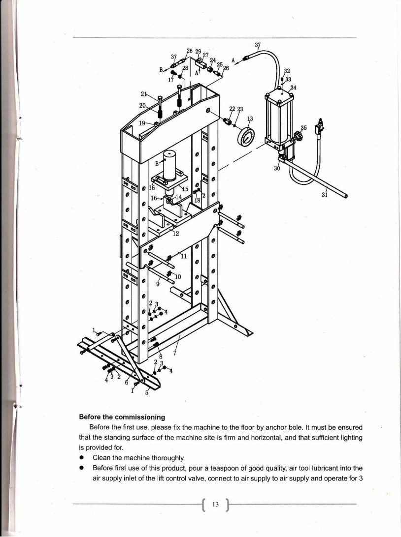
AnnexAOverall drawing of machine

I
Li
Parts List
No. Description Q'ty
I Bolt M10x25 8
2 Washer O10 t63 Lock washer O10 t24 Nut M10 T2
5 Base section 26 Suooort 47 Base 28 Bolr M10x35 49 Bed frame oin 410 Circlio 8
11 Bed frame 1
t2 Heel block 213 Pressure sause 1
l4 Serrated saddle 1
15 Ram assv 1
T6 Screw M6x8 5
T7 Bolt M12x25 1
18 Bolt M10x20 4t9 Link rod 220 Sprins 421 Bolr M10x120 422 Gause fittins 1
23 Nvlon Rins 1
24 Nut 1
25 Screw I26 O-rins 227 Banio fixins I28 Lock washer @12 I29 Banio fixine I30 Handle Socket I31 Handle 1
32 Oil filler nut 1
aa-1-1 Nvlon Rins 1
34 Pumo assv 1
35 Release valve 1
36 Bolt 1
37 Oil hose 2
t7

Annex B
Main cylinders

Parts List
Parts No Derscription Q'ty
1 Screw I
2 Nylon Ring IaJ Spring 1
4 Nut 1
5 Nut I
6 Set screw M6x8 2
7 O-ring I
8 PTFE ring 1
9 Bushing I
10 O-ring I
11 PTFE ring I
1.2 Ram I
t3 Sealing ring 2
14 Socket Head Screw I
l5 Ring ForRam I
16 Serrated Saddle 1
17 Upper Round Nut 1
18 Plate I
t9 Under Round Nut 1
20 Set screw 1
-
20
"l
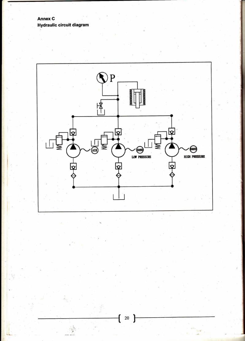
Annex G
Hydraulic circuit diagram
, \.,L-
,,1,