30GX 082-358 30HXC 080-375 Screw Compressor …...30GX 082-358 30HXC 080-375 Screw Compressor...
43
30GX 082-358 30HXC 080-375 Screw Compressor Water-Cooled Liquid Chillers and Air-Cooled Liquid Chillers Nominal cooling capacity 30HXC: 286-1300 kW Nominal cooling capacity 30GX: 282-1203 kW 50 Hz Installation, operation and maintenance instructions GLOBAL CHILLER Carrier is participating in the Eurovent Certification Programme. Products are as listed in the Eurovent Directory of Certified Products.
Transcript of 30GX 082-358 30HXC 080-375 Screw Compressor …...30GX 082-358 30HXC 080-375 Screw Compressor...

30GX 082-35830HXC 080-375Screw Compressor Water-CooledLiquid Chillers andAir-Cooled Liquid Chillers
Nominal cooling capacity 30HXC: 286-1300 kWNominal cooling capacity 30GX: 282-1203 kW
50 Hz
Installation, operation and maintenance instructions
GLOBAL CHILLER
Carrier is participating in the Eurovent Certification Programme. Products are as listed in the Eurovent Directory of Certified Products.

2
The cover photograph is for illustrative purposes only and is not part of any offer for sale or contract.
LIST OF CONTENTS
1 - INTRODUCTION ....................................................................................................................................................................... 4
1.1 - Installation safety considerations ............................................................................................................................................... 41.2 - Equipment and components under pressure ............................................................................................................................... 41.3 - Maintenance safety considerations ............................................................................................................................................ 41.4 - Repair safety considerations ...................................................................................................................................................... 5
2 - PRELIMINARY CHECKS ........................................................................................................................................................ 6
2.1 - Check equipment received ......................................................................................................................................................... 62.2 - Moving and siting the unit ......................................................................................................................................................... 6
3 - DIMENSIONS, CLEARANCES, WEIGHT DISTRIBUTION .............................................................................................. 8
3.1 - 30HXC 080-190 ......................................................................................................................................................................... 83.2 - 30HXC 200-375 ......................................................................................................................................................................... 93.3 - 30GX 082-182 .......................................................................................................................................................................... 103.4 - 30GX 207-358 .......................................................................................................................................................................... 113.5 - Multiple chiller installation ...................................................................................................................................................... 12
4 - PHYSICAL AND ELECTRICAL DATA FOR 30HXC UNITS .......................................................................................... 13
4.1 - Physical data 30HXC ............................................................................................................................................................... 134.2 - Electrical data 30HXC ............................................................................................................................................................. 134.3 - Electrical data, 30HXC compressors ....................................................................................................................................... 144.4 - Electrical data for 30HXC units with high condensing temperatures (option 150/150A) ....................................................... 144.5 - Unit characteristics 30HXC units with very low temperature option (option 6) ..................................................................... 15
5 - PHYSICAL AND ELECTRICAL DATA FOR UNITS 30GX ............................................................................................. 18
5.1 - Physical data 30GX .................................................................................................................................................................. 185.2 - Electrical data 30GX ................................................................................................................................................................ 185.3 - Electrical data, 30GX and 30HXC compressors, option 150 + 150A ..................................................................................... 19
6 - APPLICATION DATA ............................................................................................................................................................ 20
6.1 - Unit operating range ................................................................................................................................................................. 206.2 - Minimum chilled water flow .................................................................................................................................................... 206.3 - Maximum chilled water flow ................................................................................................................................................... 216.4 - Variable flow evaporator .......................................................................................................................................................... 216.5 - System minimum water volume ............................................................................................................................................... 216.6 - Cooler flow rate (l/s) ................................................................................................................................................................ 216.7 - Condenser flow rate (l/s) .......................................................................................................................................................... 216.8 - Evaporator pressure drop curve ............................................................................................................................................... 226.9 - Condenser pressure drop curve ................................................................................................................................................ 22
7 - ELECTRICAL CONNECTION .............................................................................................................................................. 23
7.1 - Electrical connections 30HXC units ........................................................................................................................................ 237.2 - Electrical connections 30GX units ........................................................................................................................................... 247.3 - Power supply ............................................................................................................................................................................ 257.4 - Voltage phase imbalance (%) ................................................................................................................................................... 257.5 - Recommended wire sections .................................................................................................................................................... 27

3
8 - WATER CONNECTIONS ....................................................................................................................................................... 29
8.1 - Operating precautions .............................................................................................................................................................. 298.2 - Water connections .................................................................................................................................................................... 308.3 - Flow control ............................................................................................................................................................................. 308.4 - Evaporator (and condenser for the 30HXC) water box bolt tightening ................................................................................... 308.5 - Frost protection ........................................................................................................................................................................ 318.6 - Operation of two units in master/slave mode ........................................................................................................................... 31
9 - MAJOR SYSTEM COMPONENTS AND OPERATION DATA ........................................................................................ 32
9.1 - Geared twin screw compressor ................................................................................................................................................ 329.2 - Pressure vessels ........................................................................................................................................................................ 329.3 - Electronic expansion device (EXV) ......................................................................................................................................... 339.4 - Economizer .............................................................................................................................................................................. 339.5 - Oil pumps ................................................................................................................................................................................. 339.6 - Motor cooling valves ................................................................................................................................................................ 349.7 - Sensors ..................................................................................................................................................................................... 34
10 - MAIN OPTIONS AND ACCESSORIES .............................................................................................................................. 35
10.1 - Compressor suction valves (option 92) .................................................................................................................................. 3510.2 - Compressor and evaporator noise insulation (30GX - option 14A) ...................................................................................... 3510.3 - Low-noise 30GX units equipped with acoustic panels (option 15) ....................................................................................... 3510.4 - Evaporator frost protection (30GX - option 41A) .................................................................................................................. 3510.5 - Year-round operation of 30GX units (option 28) .................................................................................................................. 3510.6 - Soft Start for 3- and 4-compressor 30HXC and 30GX units (option 25) .............................................................................. 3510.7 - Electric protection level of the 30HXC control boxes to IP44C (option 20) ........................................................................ 3610.8 - Tropicalised control box for 30HXC and 30GX units (option 22) ........................................................................................ 3610.9 - Brine units for low-temperature evaporator leaving applications (option 5) ......................................................................... 3610.10 - Disassembled 30HXC units (option 52) .............................................................................................................................. 3610.11 - Available fan pressure of 150 Pa for 30GX units (option 12) ............................................................................................. 36
11 - MAINTENANCE .................................................................................................................................................................... 36
11.1 - Maintenance instructions ....................................................................................................................................................... 3611.2 - Soldering and welding ............................................................................................................................................................ 3611.3 - Refrigerant charging - adding charge ..................................................................................................................................... 3611.4 - Indication of low charge on a 30HXC system ....................................................................................................................... 3711.5 - Electrical maintenance ........................................................................................................................................................... 3711.6 - Pressure transducers ............................................................................................................................................................... 3711.7 - Oil charging - low oil recharging ........................................................................................................................................... 3811.8 - Integral oil filter change ......................................................................................................................................................... 3811.9 - Filter change-out schedule ..................................................................................................................................................... 3811.10 - Filter change-out procedure ................................................................................................................................................. 3811.11 - Compressor replacement ...................................................................................................................................................... 3811.12 - Corrosion control ................................................................................................................................................................. 3911.13 - Condenser coil ...................................................................................................................................................................... 39
12 - START-UP CKECKLIST FOR 30HXC/GX LIQUID CHILLERS (USE FOR JOB FILE) .......................................... 40
4
1 - INTRODUCTION
Prior to the initial start-up of the 30HXC/GX units, the peopleinvolved in the on-site installation, start-up, operation, andmaintenance of this unit should be thoroughly familiar with theseinstructions and the specific project data for the installation site.
The 30HXC/GX liquid chillers are designed to provide a veryhigh level of safety during installation, start-up, operation andmaintenance. They will provide safe and reliable service whenoperated within their application range.
This manual provides the necessary information to familiarizeyourself with the control system before performing start-upprocedures. The procedures in this manual are arranged in thesequence required for machine installation, start-up, operationand maintenance.
Be sure you understand and follow the procedures and safetyprecautions contained in the instructions supplied with themachine, as well as those listed in this guide.
1.1 - Installation safety considerations
After the unit has been received, when it is ready to be installedor reinstalled, and before it is started up, it must be inspectedfor damage. Check that the refrigerant circuit(s) is (are) intact,especially that no components or pipes have shifted (e.g. follow-ing a shock). If in doubt, carry out a leak tightness check andverify with the manufacturer that the circuit integrity has notbeen impaired. If damage is detected upon receipt, immediatelyfile a claim with the shipping company.
Do not remove the skid or the packaging until the unit is inits final position. These units can be moved with a fork lifttruck, as long as the forks are positioned in the right placeand direction on the unit.
The units can also be lifted with slings, using only the desig-nated lifting points marked on the unit.
These units are not designed to be lifted from above. Useslings with the correct capacity, and always follow the liftinginstructions on the certified drawings supplied with the unit.
Safety is only guaranteed, if these instructions are carefullyfollowed. If this is not the case, there is a risk of materialdeterioration and injuries to personnel.
Never cover any safety devices.
This applies to the relief valve in the water circuit and therelief valve(s) in the refrigerant circuit(s).
Ensure that the valves are correctly installed, beforeoperating the unit.
In certain cases the relief valves are installed on isolatingvalves. These valves are factory-supplied lead-sealed in theopen position. This system permits isolation and removal ofthe relief valves for checking and replacing. The relief valvesare designed and installed to ensure protection againstoverpressure caused by fire.
All factory-installed relief valves are lead-sealed to preventany calibration change. If the relief valves are installed on achange-over manifold, this is equipped with a relief valve oneach of the two outlets. Only one of the two relief valves is inoperation, the other one is isolated. Never leave the change-over valve in the intermediate position, i.e. with both waysopen (locate the control element in the stop position). If arelief valve is removed for checking or replacement pleaseensure that there is always an active relief valve on each ofthe change-over valves installed in the unit.
The safety valves must be connected to discharge pipes. Thesepipes must be installed in a way that ensures that people andproperty are not exposed to refrigerant leaks. These fluidsmay be diffused in the air, but far away from any building airintake, or they must be discharged in a quantity that isappropriate for a suitably absorbing environment.
Provide a drain in the discharge circuit, close to each reliefvalve, to avoid an accumulation of condensate or rain water.
Periodic check of the relief valves: See paragraph“Maintenance safety considerations”.
Ensure good ventilation, as accumulation of refrigerant in anenclosed space can displace oxygen and cause asphyxiationor explosions.
Inhalation of high concentrations of vapour is harmful andmay cause heart irregularities, unconsciousness, or death.Vapour is heavier than air and reduces the amount of oxygenavailable for breathing. These products cause eye and skinirritation. Decomposition products are hazardous.
1.2 - Equipment and components under pressure
These products incorporate equipment or components underpressure, manufactured by Carrier or other manufacturers. Werecommend that you consult your appropriate national tradeassociation or the owner of the equipment or components underpressure (declaration, re-qualification, retesting, etc.). Thecharacteristics of this equipment/these components are givenon the nameplate or in the required documentation, suppliedwith the products.
1.3 - Maintenance safety considerations
Engineers working on the electric or refrigeration componentsmust be authorized, trained and fully qualified to do so.
All refrigerant circuit repairs must be carried out by a trainedperson, fully qualified to work on these units. He must havebeen trained and be familiar with the equipment and theinstallation. All welding operations must be carried out byqualified specialists.
Any manipulation (opening or closing) of a shut-off valvemust be carried out by a qualified and authorised engineer.These procedures must be carried out with the unit shut-down.

5
NOTE: The unit must never be left shut down with the liquidline valve closed, as liquid refrigerant can be trapped betweenthis valve and the expansion device. (This valve is situated onthe liquid line before the filter drier box.)
During any handling, maintenance and service operationsthe engineers working on the unit must be equipped withsafety gloves, glasses, shoes and protective clothing.
Never work on a unit that is still energized.
Never work on any of the electrical components, until thegeneral power supply to the unit has been cut using thedisconnect switch(es) in the control box(es).
If any maintenance operations are carried out on the unit,lock the power supply circuit in the open position ahead ofthe machine.
If the work is interrupted, always ensure that all circuits arestill deenergized before resuming the work.
ATTENTION: Even if the compressor motors have beenswitched off, the power circuit remains energized, unless theunit or circuit disconnect switch is open. Refer to the wiringdiagram for further details. Attach appropriate safety labels.
Check manual “30GX/30HXC Pro-Dialog Plus control” for adetailed explanation of the high-pressure switch test method.
Operating checks: During the life-time of the system,inspection and tests must be carried out in accordance withnational regulations.
The information on operating inspections given in annex Cof standard EN278-2 can be used if no similar criteria existin the national regulations.
Safety device checks (annex C6 – EN378-2): The safetydevices must be checked on site once a year for safety devices(high-pressure switches), and every five years for externaloverpressure devices (pressure relief valves).
If the machine operates in a corrosive environment, inspectthe protection devices more frequently.
Regularly carry out leak tests and immediately repair any leaks.
1.4 - Repair safety considerations
All installation parts must be maintained by the personnel incharge, in order to avoid material deterioration and injuries topeople. Faults and leaks must be repaired immediately. Theauthorized technician must have the responsibility to repair thefault immediately. Each time repairs have been carried out tothe unit, the operation of the safety devices must be re-checked.
If a leak occurs or if the refrigerant becomes contaminated (e.g.by a short circuit in a motor) remove the complete charge usinga recovery unit and store the refrigerant in mobile containers.
Repair the leak detected and recharge the circuit with the totalR134a charge, as indicated on the unit name plate. Certainparts of the circuit can be isolated. If leaks occur in thesesections it is possible to top up the refrigerant charge. Refer tochapter 11.2 ‘Refrigerant charging - adding charge’. Onlycharge liquid refrigerant R134a at the liquid line.
Ensure that you are using the correct refrigerant type beforerecharging the unit.
Charging any refrigerant other than the original charge type(R134a) will impair machine operation and can even lead to adestruction of the compressors. The compressors operatingwith this refrigerant type are lubricated with a synthetic polyol-ester oil.
Do not use oxygen to purge lines or to pressurize a machinefor any purpose. Oxygen gas reacts violently with oil, grease,and other common substances.
Never exceed the specified maximum operating pressures.Verify the allowable maximum high- and low-side testpressures by checking the instructions in this manual and thepressures given on the unit name plate.
Do not use air for leak testing. Use only refrigerant or drynitrogen.
Do not unweld or flamecut the refrigerant lines or any refri-gerant circuit component until all refrigerant (liquid andvapour) has been removed from chiller. Traces of vapourshould be displaced with dry air nitrogen. Refrigerant incontact with an open flame produces toxic gases.
The necessary protection equipment must be available, andappropriate fire extinguishers for the system and the refrigeranttype used must be within easy reach.
Do not siphon refrigerant.
Avoid spilling liquid refrigerant on skin or splashing it intothe eyes. Use safety goggles. Wash any spills from the skinwith soap and water. If liquid refrigerant enters the eyes,immediately and abundantly flush the eyes with water andconsult a doctor.
Never apply an open flame or live steam to a refrigerantcontainer. Dangerous overpressure can result. If it isnecessary to heat refrigerant, use only warm water.
During refrigerant removal and storage operations follow applic-able regulations. These regulations, permitting conditioningand recovery of halogenated hydrocarbons under optimum qua-lity conditions for the products and optimum safety conditionsfor people, property and the environment are described instandard NFE 29795.
Any refrigerant transfer and recovery operations must be carriedout using a transfer unit. A 3/8” SAE connector on the manualliquid line valve is supplied with all units for connection to thetransfer station. The units must never be modified to add refri-gerant and oil charging, removal and purging devices. All thesedevices are provided with the units. Please refer to the certifieddimensional drawings for the units.
6
2 - PRELIMINARY CHECKS
2.1 - Check equipment received
• Inspect the unit for damage or missing parts. If damage isdetected, or if shipment is incomplete, immediately file aclaim with the shipping company.
• Confirm that the unit received is the one ordered. Comparethe name plate data with the order.
• The unit name plate must include the followinginformation:- Version number- Model number- CE marking- Serial number- Year of manufacture and test date- Refrigerant used and refrigerant class- Refrigerant charge per circuit- Containment fluid to be used- PS: Min./max. allowable pressure (high and low
pressure side)- TS: Min./max. allowable temperature (high and low
pressure side)- Relief valve set pressure- Pressure switch cut-out pressure- Unit leak test pressure- Voltage, frequency, number of phases- Maximum current drawn- Maximum power input- Unit net weight
• Confirm that all accessories ordered for on-site installationhave been delivered, and are complete and undamaged.
• Do not keep the 30HXC units outside where they areexposed to the weather, as the sensitive control mechanismand the electronic modules may be damaged.
The unit must be checked periodically during its wholeoperating life to ensure that no shocks (handling accessories,tools etc.) have damaged it. If necessary, the damaged partsmust be repaired or replaced. See also chapter “Maintenance”.
2.2 - Moving and siting the unit
2.2.1 - MovingSee chapter 1.1 "Installation safety considerations".
2.2.2 - Siting the unit
Always refer to the chapter "Dimensions and clearances" toconfirm that there is adequate space for all connections andservice operations. For the centre of gravity coordinates, theposition of the unit mounting holes, and the weight distribu-tion points, refer to the certified dimensional drawing suppliedwith the unit.
Typical applications of these units are in refrigerationsystems, and they do not require earthquake resistance.Earthquake resistance has not been verified.
CAUTION: Only use slings at the designated lifting pointswhich are marked on the unit.
Do not re-use disposable (non-returnable) cylinders or attemptto refill them. It is dangerous and illegal. When cylinders areempty, evacuate the remaining gas pressure, and move thecylinders to a place designated for their recovery. Do notincinerate.
Do not attempt to remove refrigerant circuit components orfittings, while the machine is under pressure or while it isrunning. Be sure pressure is at 0 kPa before removingcomponents or opening a circuit.
Do not attempt to repair or recondition any safety deviceswhen corrosion or build-up of foreign material (rust, dirt,scale, etc.) is found within the valve body or mechanism. Ifnecessary, replace the device. Do not install safety valves inseries or backwards.
ATTENTION: No part of the unit must use feet, racks orsupports during operation. Periodically monitor and repair orif necessary replace any component or piping that showssigns of damage.
The refrigerant lines can break under the weight and releaserefrigerant, causing personal injury.
Do not climb on a machine. Use a platform, or staging towork at higher levels.
Use mechanical lifting equipment (crane, hoist, winch, etc.)to lift or move heavy components. For lighter components,use lifting equipment when there is a risk of slipping orlosing your balance.
Use only original replacement parts for any repair or compo-nent replacement. Consult the list of replacement parts thatcorresponds to the specification of the original equipment.
Do not drain water circuits containing industrial brines,without informing the technical service department at theinstallation site or a competent body first.
Close the entering and leaving water shutoff valves and purgethe unit water circuit, before working on the components in-stalled on the circuit (screen filter, pump, water flow switch, etc.).
Do not loosen the water box bolts until the water boxes havebeen completely drained.
Periodically inspect all valves, fittings and pipes of therefrigerant and hydronic circuits to ensure that they do notshow any corrosion or any signs of leaks.

7
Before siting the unit check that:• the permitted loading at the site is adequate or that
appropriate strenghtening measures have been taken.• the unit is installed level on an even surface (maximum
tolerance is 5 mm in both axes).• there is adequate space above the unit for air flow and to
ensure access to the components.• the number of support points is adequate and that they are
in the right places.• the location is not subject to flooding.• for outdoor installations, where heavy snowfall is likely
and long periods of sub-zero temperatures are normal,provision has to be made to prevent snow accumulating byraising the unit above the height of drifts normallyexperienced. Baffles may be necessary to deflect strongwinds. They must not restrict air flow into the unit.
CAUTION: Before lifting the unit, check that all casingpanels are securely fixed in place. Lift and set down the unitwith great care. Tilting and jarring can damage the unit andimpair unit operation.
If 30GX units are hoisted with rigging, it is advisable to protectcoils against crushing while a unit is being moved. Use strutsor spreader bars to spread the slings above the unit. Do not tilta unit more than 15°.
WARNING: Never push or lever on any of the enclosurepanels of the unit. Only the base of the unit frame is designedto withstand such stresses.
Checks before system start-up
Before the start-up of the refrigeration system, the completeinstallation, including the refrigeration system must be verifiedagainst the installation drawings, dimensional drawings, systempiping and instrumentation diagrams and the wiring diagrams.
During the installation test national regulations must befollowed. If no national regulation exists, paragraph 9-5 ofstandard EN 378-2 can be used as a guide.
External visual installation checks:• Compare the complete installation with the refrigeration
system and power circuit diagrams.• Check that all components comply with the design
specifications.• Check that all safety documents and equipments that are
required by current European standards are present.• Verify that all safety and environmental protection devices
and arrangements are in place and comply with the currentEuropean standard.
• Verify that all relevant documents for pressure vessels(certificates, name plates, files, instruction manuals etc.)required by the current European standards are present.
• Verify the free passage of access and safety routes.• Check that ventilation in the plant room is adequate.• Check that refrigerant detectors are present.• Verify the instructions and directives to prevent the
deliberate removal of refrigerant gases that are harmful tothe environment.
• Verify the installation of connections.• Verify the supports and fixing elements (materials, routing
and connection).• Verify the quality of welds and other joints.• Check the protection against mechanical damage.• Check the protection against heat.• Check the protection of moving parts.• Verify the accessibility for maintenance or repair and to
check the piping.• Verify the status of the valves.• Verify the quality of the thermal insulation and of the
vapour barriers.

8
3 - DIMENSIONS, CLEARANCES, WEIGHT DISTRIBUTION
3.1 - 30HXC 080-190
Legend:All dimensions are in mm.
Evaporator
Condenser
Clearances required for operation and maintenance
Clearances required for heat exchanger tube removal. Clearances Dand E can be either on the left or on the right hand side.
Water inlet
Water outlet
Power supply
1
2
3
4
30HXC A B C D E F
080-090-100 2558 980 1800 2200 1000 385110 2565 980 1850 2200 1000 385120-130-140-155 3275 980 1816 2990 1000 689175-190 3275 980 1940 2990 1000 689
NOTE: Refer to the certified dimensional drawings suppliedwith the unit, when designing an installation.
30HXC-080 30HXC-09030HXC-10030HXC-110
AD
B
600
500
4
700
4
3
C
E
3
3
F
1
2
9
3 - DIMENSIONS, CLEARANCES, WEIGHT DISTRIBUTION (cont’d)
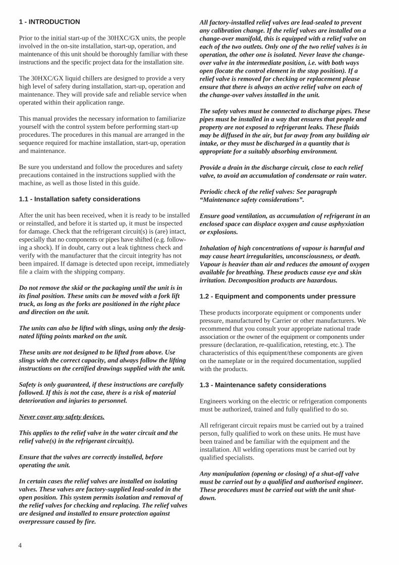
3.2 - 30HXC 200-375
Legend:All dimensions are in mm.
Evaporator
Condenser
Clearances required for operation and maintenance
Clearances required for heat exchanger tube removal. Clearances Dand E can be either on the left or on the right hand side.
Water inlet
Water outlet
Power supply
1
2
3
4 30HXC A B C D E F
200 3903 1015 1980 3600 1000 489230-260-285 3924 1015 2060 3600 1000 489310-345-375 4533 1015 2112 4200 1000 503
NOTE: Refer to the certified dimensional drawings suppliedwith the unit, when designing an installation.
4
2
E
500
B
3
A
C
D
7003
4
5003
F
1

10
3 - DIMENSIONS, CLEARANCES, WEIGHT DISTRIBUTION (cont’d)
3.3 - 30GX 082-182
Standard units
Legend:All dimensions are in mm.
Clearances required for operation and maintenance
Clearances required for tube removal
Thickness of sound absorption kit
Clearances required for maintenance and air flow
Water inlet
Water outlet
Power supply
Air outlet - do not obstruct
30GX A B C1
082-092-102 2967 1900 414112-122-132 3425 1700 617152-162 4340 2400 1151182 5994 1850 2226
NOTE: Refer to the certified dimensional drawings suppliedwith the unit, when designing an installation.
30GX-082 30GX-092 30GX-102 30GX-112 30GX-122 30GX-132
30GX-152 30GX-162 30GX-182
500500
2297
1830
2254
1830
4
1 1
4
22
A
B
500500
1830
2254
1830
4
1 1
4
22
B
3
230
230
C1
1351
Units with low and very low noise levels
1
2
3
4

11
3 - DIMENSIONS, CLEARANCES, WEIGHT DISTRIBUTION (cont’d)
3.4 - 30GX 207-358
Standard units
30GX A B C1 C2
207-227 5994 2850 621 2662247-267 6909 2850 621 2662298 7824 2050 1036 3578328-358 8739 1150 1951 4493
NOTE: Refer to the certified dimensional drawings suppliedwith the unit, when designing an installation.
Legend:All dimensions are in mm.
Clearances required for operation and maintenance
Clearances required for tube removal
Thickness of sound absorption kit
Clearances required for maintenance and air flow
Water inlet
Water outlet
Power supply
Air outlet - do not obstruct
1
2
3
4
2297
A
500500
1830
1830
B
4
11
4
2 2
1351
500500
230
2254
B
4
11
4
2 2
1830
230
1830
3
2254
C1
C2
Units with low and very low noise levels

12
3.5 - Multiple chiller installation
NOTE: If the walls are higher than 2 m, contact the factory.
LegendA WallB Units
Notes:Unit must have clearances for air flow as follows:Top: do not restrict in any way
In case of multiple chillers (up to four units), the respective clearance betweenthem should be increased from 1830 to 2000 mm for the side space requirement.
If necessary, add the required clearances for evaporator tube removal.
Surface solide
2000
1830
2000
1830
2000
2000
1525
1525
A
B
B
B
B
B B
B B
A

13
4 - PHYSICAL AND ELECTRICAL DATA FOR 30HXC UNITS
4.1 - Physical data 30HXC
30HXC 080 090 100 110 120 130 140 155 175 190 200 230 260 285 310 345 375
Nominal cooling capacity* kW 286 312 348 374 412 449 509 541 598 651 699 812 897 985 1106 1204 1300
Operating weight kg 2274 2279 2302 2343 2615 2617 2702 2712 3083 3179 3873 4602 4656 4776 5477 5553 5721
Refrigerant charge** kg HFC-134aCircuit A** 33 33 32 31 49 51 48 51 54 56 92 115 117 117 109 104 119Circuit B** 34 34 30 35 52 47 48 50 50 59 54 63 75 75 106 102 137
Oil*** Polyolester oil CARRIER SPEC. PP 47-32Circuit A/B l 17/17 17/17 17/17 17/17 17/17 17/17 17/17 17/17 17/17 17/17 30/17 30/17 30/17 30/17 34/34 34/34 34/34
Compressors† Semi-hermetic, twin-screwSize - Circuit A† 39 46 46 56 56 66 80 80 80 80+ 66/56 80/56 80/80 80+/80+ 80/66 80/80 80+/80+Size - Circuit B† 39 39 46 46 56 56 56 66 80 80+ 66 80 80 80+ 80/66 80/80 80+/80+
Capacity control PRO-DIALOG Plus controlNo. of control steps 6 6 6 6 6 6 6 6 6 6 8 8 8 8 10 10 10Minimum step capacity % 19 19 21 19 21 19 17 19 21 21 14 14 14 14 10 10 10
Evaporator Shell and tube with internally finned copper tubesNet water volume l 50 50 58 69 65 65 75 75 88 88 126 155 170 170 191 208 208Water connections Victaulic connectionsInlet/outlet in 4 4 4 5 5 5 5 5 5 5 6 6 6 6 8 8 8Drain and vent (NPT) in 3/8 3/8 3/8 3/8 3/8 3/8 3/8 3/8 3/8 3/8 3/8 3/8 3/8 3/8 3/8 3/8 3/8Max. water side operating pressure kPa 1000 1000 1000 1000 1000 1000 1000 1000 1000 1000 1000 1000 1000 1000 1000 1000 1000
Condenser Shell and tube with internally finned copper tubesNet water volume l 48 48 48 48 78 78 90 90 108 108 141 190 190 190 255 255 255Water connections Victaulic connectionsInlet/outlet in 5 5 5 5 5 5 5 5 6 6 6 8 8 8 8 8 8Drain and vent (NPT) in 3/8 3/8 3/8 3/8 3/8 3/8 3/8 3/8 3/8 3/8 3/8 3/8 3/8 3/8 3/8 3/8 3/8Max. water side operating pressure kPa 1000 1000 1000 1000 1000 1000 1000 1000 1000 1000 1000 1000 1000 1000 1000 1000 1000
* Standard Eurovent conditions: Evaporator entering/leaving water temperature 12°C and 7°C. Condenser entering/leaving water temperature 30°C/35°C. Evaporator and condenser foulingfactor = 0.000044 m2 K/W.Not applicable to high condensing temperature units - please refer to electronic selection catalogue.
** The weights shown are guidelines only. For the unit refrigerant charge please refer to the unit nameplate.*** For options 150 and 150A the units are supplied with an additional charge of 3 litres per compressor.† Nominal size per compressor. The compressor size is the same as its nominal cooling capacity in tons of refrigeration (1 ton = 3.517 kW).
4.2 - Electrical data 30HXC
30HXC 080 090 100 110 120 130 140 155 175 190 200 230 260 285 310 345 375
Power circuitNominal power supply (Un)* V-ph-Hz 400-3-50Voltage range V 360-440
Control circuit supply The control circuit is supplied via the factory-installed transformer
Nominal power input* kW 53 62 67 76 80 89 102 112 121 129 140 164 192 195 221 250 263
Nominal current drawn * A 101 115 127 143 149 168 190 207 226 234 255 294 337 354 399 448 477
Max. power input** kW 87 97 108 119 131 144 161 175 192 212 223 257 288 318 350 384 424Circuit A kW - - - - - - - - - - 144 161 192 212 175 192 212Circuit B kW - - - - - - - - - - 79 96 96 106 175 192 212
Cosine phi, unit at full load 0.88 0.88 0.88 0.88 0.89 0.88 0.88 0.89 0.89 0.89 0.88 0.89 0.89 0.89 0.89 0.89 0.89
Max. current drawn (Un - 10%)*** A 158 176 195 215 235 259 289 314 344 379 401 461 517 568 628 688 758Circuit A*** A - - - - - - - - - - 259 289 344 379 314 344 379Circuit B*** A - - - - - - - - - - 142 172 172 189 314 344 379
Maximum current drawn (Un)*** A 143 160 177 195 213 236 263 285 312 344 365 419 468 516 570 624 688Circuit A*** A - - - - - - - - - - 236 263 312 344 285 312 344Circuit B*** A - - - - - - - - - - 129 156 156 172 285 312 344
Maximum starting current,standard unit (Un)**** A 181 206 223 249 267 298 333 355 382 442 841 978 1027 1200 1129 1184 1373Circuit A*** A - - - - - - - - - - 712 822 871 1028 844 871 1028Circuit B*** A - - - - - - - - - - 605 715 715 856 844 871 1028
Max. starting current/max. currentdraw ratio, unit 1.26 1.28 1.26 1.27 1.25 1.26 1.27 1.24 1.22 1.28 2.31 2.33 2.19 2.32 1.98 1.89 1.99Max. starting current/max. currentdraw ratio, circuit A - - - - - - - - - - 3.02 3.13 2.79 2.99 2.96 2.79 2.99Max. starting current/max. currentdraw ratio, circuit B - - - - - - - - - 4.70 4.58 4.58 4.97 2.96 2.79 2.99
Max. starting current - reducedcurrent start (Un) **** A std. std. std. std. std. std. std. std. std. std. 636 683 732 824 834 889 997Circuit A A std. std. std. std. std. std. std. std. std. std. 507 527 576 652 549 576 652Circuit B A std. std. std. std. std. std. std. std. std. std. 330 370 370 385 549 576 652
Max.starting current - red. currentstart/max. current draw ratio, unit std. std. std. std. std. std. std. std. std. std. 1.74 1.63 1.56 1.60 1.46 1.42 1.45Circuit A std. std. std. std. std. std. std. std. std. std. 2.15 2.00 1.84 1.89 1.93 1.84 1.98Circuit B std. std. std. std. std. std. std. std. std. std. 2.56 2.37 2.37 2.24 1.93 1.84 1.89
Three-phase short circuitholding current kA 25 25 25 25 25 25 25 25 25 25 N/A N/A N/A N/A N/A N/A N/ACircuit A kA - - - - - - - - - - 25 25 25 25 25 25 25Circuit B kA - - - - - - - - - - 15 15 15 15 25 25 25
Customer standby capacity,unit or circuit B, for evaporatorwater pump connections† kW 8 8 8 11 11 11 15 15 15 15 15 18 18 30 30 30 30
* Standard Eurovent conditions: Evaporator entering/leaving water temperature 12°C and 7°C. Condenser entering/leaving water temperature 30°C/35°C.** Power input, compressor, at unit operating limits (evaporator water entering/leaving temperature = 15°C/10°C, condenser entering/leaving water temperature = 45°C/50°C) and a nominal
voltage of 400 V (data given on the unit name plate).*** Maximum unit operating current at maximum unit power input.**** Maximum instantaneous starting current (maximum operating current of the smallest compressor(s) + locked rotor current or reduced starting current of the largest compressor)† Current and power inputs not included in the values above.N/A Not applicable.

14
4.3 - Electrical data, 30HXC compressors
Reference Size I nom. MHA LRA LRA (Y) LRA (S) 1 cp LRA (S) 2 cp
06NW2146S7N 39 50 79 344 109 NA NA06NW2174S7N 46 60 97 423 134 NA NA06NW2209S7N 56 71 117 506 160 260 35006NW2250S7N 66 86 142 605 191 330 40006NW2300S5N 80 105 172 715 226 370 42006NW2300S5E 80+ 114 189 856 270 385 480
Legend:06NW - Compressor for water-cooled unitsN - Non-economized compressorE - Economized compressorINOM - Average current draw of the compressor at Eurovent conditionsMHA - Must hold amperes (maximum operating current) at 360 VLRA - Locked rotor current with across-the-line startLRA (Y) - Locked rotor current at reduced current (star/delta start-up mode)LRA (S) 1 cp. - Start-up with reduced current with electronic starter (start-up duration 3 seconds max.) for one compressor per circuitLRA (S) 2 cp. - Start-up with reduced current with electronic starter (start-up duration 3 seconds max.) for two compressors per circuit
4.4 - Electrical data for 30HXC units with high condensing temperatures (option 150/150A)
30HXC 080 090 100 110 120 130 140 155 175 190 200 230 260 285 310 345 375
Power circuitNominal power supply (Un)* V-ph-Hz 400-3-50Voltage range V 360-440
Control circuit supply The control circuit is supplied via the factory-installed transformer
Max. power input* kW 108 122 136 149 163 180 196 213 229 287 278 310 343 431 426 458 574Circuit A kW - - - - - - - - - - 180 196 229 287 213 229 287Circuit B kW - - - - - - - - - - 98 114 114 144 213 229 287
Max. current drawn (Un - 10%)** A 198 223 247 271 295 325 355 385 415 516 502 562 622 774 770 830 1032Circuit A A - - - - - - - - - - 325 355 415 516 385 415 516Circuit B A - - - - - - - - - - 177 207 207 258 385 415 516
Maximum current drawn (Un)** A 180 203 225 246 268 295 323 350 377 469 456 512 566 704 700 754 938Circuit A A - - - - - - - - - - 295 323 377 469 350 377 469Circuit B A - - - - - - - - - - 161 189 189 235 350 377 469
Maximum starting current,standard unit (Un)*** A 281 316 338 382 404 437 521 548 576 635 1255 1549 1603 1734 1737 1792 1969Circuit A*** A - - - - - - - - - - 1094 1360 1415 1500 1387 1415 1500Circuit B*** A - - - - - - - - - - 960 1226 1226 1265 1387 1415 1500
Max. starting current/max. currentdraw ratio, unit 1.56 1.56 1.51 1.55 1.51 1.48 1.62 1.57 1.53 1.35 2.75 3.03 2.83 2.46 2.48 2.38 2.10Max. starting current/max. currentdraw ratio, circuit A - - - - - - - - - - 3.71 4.22 3.75 3.19 3.97 3.75 3.19Max. starting current/max. currentdraw ratio, circuit B - - - - - - - - - 5.96 6.50 6.50 5.39 3.97 3.75 3.19
Max. starting current - reducedcurrent start (Un) *** A std. std. std. std. std. std. std. std. std. std. 870 933 987 1129 1121 1176 1364Circuit A A std. std. std. std. std. std. std. std. std. std. 709 744 799 895 771 799 895Circuit B A std. std. std. std. std. std. std. std. std. std. 435 490 490 510 771 799 895
Max.starting current - red. currentstart/max. current draw ratio, unit std. std. std. std. std. std. std. std. std. std. 1.91 1.82 1.75 1.60 1.60 1.56 1.45Circuit A std. std. std. std. std. std. std. std. std. std. 2.40 2.31 2.12 1.91 2.21 2.12 1.91Circuit B std. std. std. std. std. std. std. std. std. std. 2.70 2.60 2.60 2.17 2.21 2.12 1.91
Three-phase short circuit holding current kA 25 25 25 25 25 25 25 25 25 25 N/A N/A N/A N/A N/A N/A N/ACircuit A kA - - - - - - - - -. - 25 25 25 25 25 25 25Circuit B kA - - - - - - - - - - 15 15 15 15 25 25 25
Customer standby capacity, unitor circuit B, for evaporatorwater pump connections† kW 8 8 8 11 11 11 15 15 15 15 15 18 18 30 30 30 30
* Power input, compressor, at unit operating limits (evaporator water entering/leaving temperature = 15°C/10°C, condensing temperature = 68°C) and a nominal voltage of 400 V (data given onthe unit name plate).
** Maximum unit operating current at maximum unit power input.*** Maximum instantaneous starting current (maximum operating current of the smallest compressor(s) + locked rotor current or reduced starting current of the largest compressor)† Current and power inputs not included in the values aboveN/A Not applicable

15
The 30HXC 080-375 units for high condensing temperaturesare directly derived from the standard models. Their applicat-ion range is the same as that of the standard units, but permitsoperation at condenser leaving water temperatures up to 63°C.The PRO-DIALOG control offers all the advantages of thestandard units, plus control of the condenser leaving watertemperature.
The main modifications are:• Use of 30GX compressors (example: 06NA2300S5N
instead of 06NW 2300S5N).• Modification of electrical components to operate with
compressors for high condensing temperatures.• Modification of heat exchangers to meet pressure code
requirements (if necessary).
Option 150These units are designed for traditional applications for water-cooled units, but for higher condender leaving water tempera-tures than 50°C.
Like the standard units they are equipped with condenserentering and leaving water sensors.
It is possible to control the machine at the condenser wateroutlet, requiring a factory configuration change and the use of aheating/cooling inlet reversing device.
Option 150AThese units are designed for water-to-water heat pumps.
They are factory configured as heat pumps (heating/coolingcontrol as a function of the remote reversing device). Thecondenser incorporates thermal insulation that is identical tothat of the evaporator.
Technical informationAll information is identical to that of the standard 30HXCunits, except for the following paragraphs.
SelectionThere are no nominal conditions for this unit type. The selec-tion is made using the current electronic catalogue.
DimensionsThese are identical to those of the standard 30HXC units. Theonly difference is in the diameter of the incoming field wiringconnection, described in the chapter “Recommended selection”.Refer to the dimensional drawings for these units, beforeproceeding with the wiring.
CompressorSee table in chapter 5.3.
Options and accessoriesAll options available for the standard 30HXC units arecompatible, except low-temperature option 5 for the evaporatoravailable in the special unit.
ATTENTION: If units have two different operating modes -one with high condensing temperature and the other with lowcondensing temperature - and the transition is made with theunit in operation, the temperature must not vary by morethan 3 K per minute. In cases where this is not possible, it isrecommended to go through a unit start/stop switch (remotestart/stop available for standard units).
4.5 - Unit characteristics for 30HXC units with verylow temperature option (option 6)
The 30HXC units with the very low temperature option aredirectly derived from the 30HXC models equipped with thehigh condensing temperature option (option 150). Unit sizesavailable with the very low temperature option are the following:30HXC 090, 110, 130, 155, 175, 200, 230, 260, 310, 345.
Their application range allows the production of glycol/watersolution down to -10°C with ethylene glycol at 35% (by weight)or down to -7°C with propylene glycol at 30% (by weight). Theprecision of these amounts is critical for correct unit operation.
In addition to the ones already listed for the high condensingtemperature option (see chapter 4.4) the main modificationsare:- the evaporator is equipped with reinforced thermal 38 mm
insulation,- the electronic expansion valves are changed,- the use of a wide-band oil differential sensor.
All technical data is the same as for the 30HXC units withoption 150 except for the following chapters:
4.5.1 - Options and accessoriesThe options available for the 30HXC units equipped with thevery low temperature option are as follows: 20, 22, 60, 61, 84,84D, 84R, 92, 104A, 107, 107A, 152, 193, 194, 197, 199.
4.5.2 - Operating range, 30HXC units with very lowtemperature option
30HXC evaporator with 35% ethylene glycol °C Minimum Maximum
Evaporator entering water temperature -7.2 21Evaporator leaving water temperature -10 15
30HXC evaporator with 30% polypropylene glycol
Evaporator entering water temperature -4.2 21Evaporator leaving water temperature -7 15
30HXC condenser
Condenser entering water temperature 20 50Condenser leaving water temperature 25 55Outdoor air temperature 6 40
For very low temperature applications the anti-freeze solutionis critical for correct unit operation. The following amounts (byweight) are required:
Evaporator leaving water, °C Ethylene glycol, % Propylene glycol, %
-6 25 27-7 28 30-8 30 NA-9 33 NA-10 35 NA
16
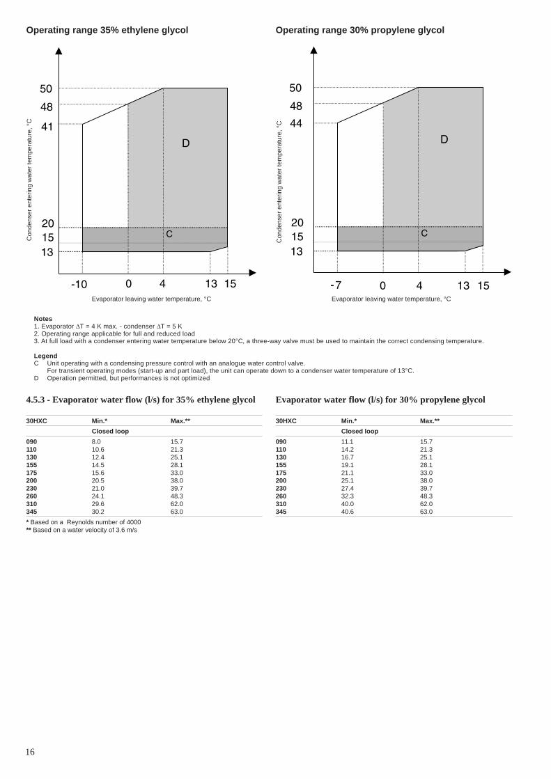
Operating range 35% ethylene glycol Operating range 30% propylene glycol
Evaporator leaving water temperature, °C
Notes1. Evaporator ∆T = 4 K max. - condenser ∆T = 5 K2. Operating range applicable for full and reduced load3. At full load with a condenser entering water temperature below 20°C, a three-way valve must be used to maintain the correct condensing temperature.
LegendC Unit operating with a condensing pressure control with an analogue water control valve.
For transient operating modes (start-up and part load), the unit can operate down to a condenser water temperature of 13°C.D Operation permitted, but performances is not optimized
4.5.3 - Evaporator water flow (l/s) for 35% ethylene glycol
30HXC Min.* Max.**
Closed loop
090 8.0 15.7110 10.6 21.3130 12.4 25.1155 14.5 28.1175 15.6 33.0200 20.5 38.0230 21.0 39.7260 24.1 48.3310 29.6 62.0345 30.2 63.0
* Based on a Reynolds number of 4000** Based on a water velocity of 3.6 m/s
Evaporator water flow (l/s) for 30% propylene glycol
30HXC Min.* Max.**
Closed loop
090 11.1 15.7110 14.2 21.3130 16.7 25.1155 19.1 28.1175 21.1 33.0200 25.1 38.0230 27.4 39.7260 32.3 48.3310 40.0 62.0345 40.6 63.0
Con
dens
er e
nter
ing
wat
er te
mpe
ratu
re, °
C
Con
dens
er e
nter
ing
wat
er te
mpe
ratu
re, °
C
Evaporator leaving water temperature, °C

17
4.5.4 - Evaporator pressure drop curve, units for very low temperature
The evaporator is equipped with heat insulation of 38 mm thick polyurethane foam.
Cooler pressure drop, 30HXC low-brine version
Pure water air flow rate, l/s
Pre
ssur
e dr
op, k
Pa
0,01
0,1
1
10
100
1000
1 10 100
HXC 310 & 345
HXC 260
HXC 230
HXC 155
HXC 130
HXC 110
HXC 090
HXC 175
HXC 200
18
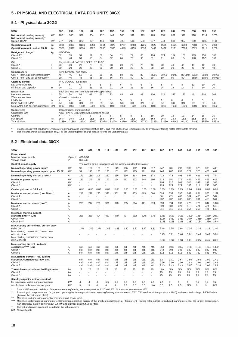
5 - PHYSICAL AND ELECTRICAL DATA FOR UNITS 30GX
5.1 - Physical data 30GX
30GX 082 092 102 112 122 132 152 162 182 207 227 247 267 298 328 358
Net nominal cooling capacity* kW 282 305 329 384 412 443 500 549 599 705 751 809 916 990 1116 1203Net nominal cooling capacity*Option 15LN* kW 277 299 322 377 404 434 490 518 588 677 744 801 907 980 1083 1191
Operating weight kg 3066 3097 3106 3350 3364 3378 3767 3783 4725 5520 5535 6121 6293 7339 7779 7950Operating weight - option 15LN kg 3566 3597 3606 3922 3936 3950 4443 4459 5653 6462 6477 7191 7363 8521 9011 9268
Refrigerant charge** kg HFC-134aCircuit A** 52 55 51 51 56 54 71 71 86 124 124 154 169 163 156 169Circuit B** 53 48 51 50 54 52 66 72 90 81 81 88 104 148 157 167
Oil Polyolester oil CARRIER SPEC. PP 47-32Circuit A l 20 20 20 20 20 20 20 20 20 40 40 40 40 40 40 40Circuit B l 20 20 20 20 20 20 20 20 20 20 20 20 20 40 40 40
Compressors Semi-hermetic, twin-screwCirc. A - nom. size per compressor** 46 46 56 56 66 66 80 80 80+ 66/56 80/66 80/80 80+/80+ 80/80 80/80 80+/80+Circ. B. nom. size per compressor** 39 46 46 56 56 66 66 80 80+ 80 80 80 80+ 66/66 80/80 80+/80+
Capacity control PRO-DIALOG Plus controlNo. of control steps 6 6 6 6 6 6 6 6 6 8 8 8 8 10 10 10Minimum step capacity % 19 21 19 21 19 21 19 21 21 16 14 14 14 9 10 10
Evaporator Shell and tube with internally finned copper tubesNet water volume l 50 58 58 69 69 73 65 65 88 126 126 155 170 191 208 208Water connections Victaulic connectionsInlet/outlet in 4 4 4 5 5 5 5 5 5 6 6 6 6 8 8 8Drain and vent (NPT) in 3/8 3/8 3/8 3/8 3/8 3/8 3/8 3/8 3/8 3/8 3/8 3/8 3/8 3/8 3/8 3/8Max. water side operating pressure kPa 1000 1000 1000 1000 1000 1000 1000 1000 1000 1000 1000 1000 1000 1000 1000 1000
Condensers Copper tubes, aluminium finsCondenser fans Axial FLYING BIRD 2 fan with a rotating shroudQuantity 4 4 4 6 6 6 8 8 8 10 10 12 12 14 16 16Fan speed r/s 15.8 15.8 15.8 15.8 15.8 15.8 15.8 15.8 15.8 15.8 15.8 15.8 15.8 15.8 15.8 15.8Total air flow l/s 21380 21380 21380 32070 32070 32070 42760 42760 42760 53450 53450 64140 64140 74830 85520 85520
* Standard Eurovent conditions: Evaporator entering/leaving water temperature 12°C and 7°C. Outdoor air temperature 35°C, evaporator fouling factor of 0.000044 m2 K/W.** The weights shown are guidelines only. For the unit refrigerant charge please refer to the unit nameplate.
5.2 - Electrical data 30GX
30GX 082 092 102 112 122 132 152 162 182 207 227 247 267 298 328 358
Power circuitNominal power supply V-ph-Hz 400-3-50Voltage range V 360-440
Control circuit supply The control circuit is supplied via the factory-installed transformer
Nominal operating power input* kW 98 108 120 128 149 166 182 198 217 242 285 297 332 370 395 435Nominal operating power input - option 15LN* kW 99 110 123 130 151 172 185 201 220 248 287 299 329 373 406 447
Nominal operating current drawn * A 170 188 206 220 256 290 313 340 373 413 478 498 547 621 675 744
Maximum power input** kW 132 145 159 177 194 211 232 248 306 318 351 372 459 459 496 612Circuit A kW - - - - - - - - - 194 227 248 306 248 248 306Circuit B kW - - - - - - - - - 124 124 124 153 211 248 306
Cosine phi, unit at full load 0.85 0.85 0.86 0.85 0.85 0.86 0.85 0.85 0.86 0.85 0.85 0.85 0.86 0.85 0.85 0.86
Maximum current drawn (Un - 10%)*** A 248 272 295 331 361 391 433 463 564 593 653 695 847 854 926 1129Circuit A A - - - - - - - - - 361 421 463 564 463 463 564Circuit B A - - - - - - - - - 232 232 232 283 391 463 564
Maximum current drawn (Un)*** A 225 247 268 301 328 355 394 421 513 539 594 632 770 776 842 1026Circuit A A - - - - - - - - - 328 383 421 513 421 421 513Circuit B A - - - - - - - - - 211 211 211 257 355 421 513
Maximum starting current,standard unit**** (Un) A 338 360 404 437 470 497 592 620 679 1338 1631 1669 1800 1814 1880 2057Circuit A**** A - - - - - - - - - 1127 1420 1459 1544 1459 1459 1544Circuit B**** A - - - - - - - - - 1248 1248 1248 1287 1154 1459 1544
Max. starting current/max. current drawratio, unit 1.51 1.46 1.51 1.45 1.43 1.40 1.50 1.47 1.32 2.48 2.75 2.64 2.34 2.34 2.23 2.00Max. starting current/max. current drawratio, circuit A - - - - - - - - - 3.43 3.71 3.46 3.01 3.46 3.46 3.01Max. starting current/max. current drawratio, circuit B - - - - - - - - - 5.93 5.93 5.93 5.01 3.25 3.46 3.01
Max. starting current - reducedcurrent start**** (Un) A std. std. std. std. std. std. std. std. std. 953 1015 1053 1195 1198 1264 1452Circuit A A std. std. std. std. std. std. std. std. std. 742 804 843 939 843 843 939Circuit B A std. std. std. std. std. std. std. std. std. 512 512 512 532 769 843 939
Max.starting current - red. currentstart/max. current draw ratio, unit std. std. std. std. std. std. std. std. std. 1.77 1.71 1.67 1.55 1.54 1.50 1.41Circuit A std. std. std. std. std. std. std. std. std. 2.26 2.10 2.00 1.83 2.00 2.00 1.83Circuit B std. std. std. std. std. std. std. std. std. 2.43 2.43 2.43 2.07 2.16 2.00 1.83
Three-phase short-circuit holding current kA 25 25 25 25 25 25 25 25 25 N/A N/A N/A N/A N/A N/A N/ACircuit A kA - - - - - - - - -. 25 25 25 25 25 25 25Circuit B kA - - - - - - - - - 25 25 25 25 25 25 25
Standby capacity, unit or circuit A†for evaporator water pump connections kW 4 4 4 5.5 5.5 5.5 7.5 7.5 7.5 7.5 9 9 9 15 15 15and for heat reclaim condenser pump kW 3 3 4 4 4 5.5 5.5 5.5 N/A 5.5 7.5 7.5 N/A 9 9 N/A
* Standard Eurovent conditions: Evaporator entering/leaving water temperature 12°C and 7°C. Outdoor air temperature 35°C.** Power input, compressor and fan, at unit operating limits (evaporator water entering/leaving temperature = 15°C/10°C, outdoor air temperature = 46°C) and a nominal voltage of 400 V (data
given on the unit name plate).*** Maximum unit operating current at maximum unit power input.**** Maximum instantaneous starting current (maximum operating current of the smallest compressor(s) + fan current + locked rotor current or reduced starting current of the largest compressor).
Fan electrical data = power input 2.4 kW and current draw 5.5 A per fan.† Current and power inputs not included in the values aboveN/A Not applicable
19
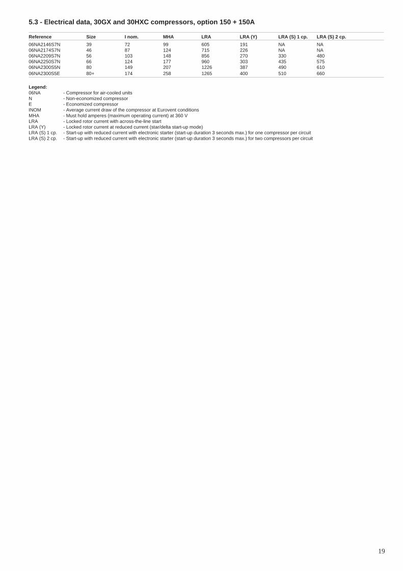
5.3 - Electrical data, 30GX and 30HXC compressors, option 150 + 150A
Reference Size I nom. MHA LRA LRA (Y) LRA (S) 1 cp. LRA (S) 2 cp.
06NA2146S7N 39 72 99 605 191 NA NA06NA2174S7N 46 87 124 715 226 NA NA06NA2209S7N 56 103 148 856 270 330 48006NA2250S7N 66 124 177 960 303 435 57506NA2300S5N 80 149 207 1226 387 490 61006NA2300S5E 80+ 174 258 1265 400 510 660
Legend:06NA - Compressor for air-cooled unitsN - Non-economized compressorE - Economized compressorINOM - Average current draw of the compressor at Eurovent conditionsMHA - Must hold amperes (maximum operating current) at 360 VLRA - Locked rotor current with across-the-line startLRA (Y) - Locked rotor current at reduced current (star/delta start-up mode)LRA (S) 1 cp. - Start-up with reduced current with electronic starter (start-up duration 3 seconds max.) for one compressor per circuitLRA (S) 2 cp. - Start-up with reduced current with electronic starter (start-up duration 3 seconds max.) for two compressors per circuit
20
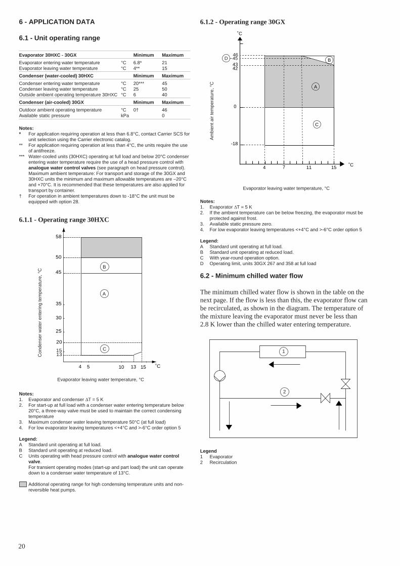
6 - APPLICATION DATA
6.1 - Unit operating range
Evaporator 30HXC - 30GX Minimum Maximum
Evaporator entering water temperature °C 6.8* 21Evaporator leaving water temperature °C 4** 15
Condenser (water-cooled) 30HXC Minimum Maximum
Condenser entering water temperature °C 20*** 45Condenser leaving water temperature °C 25 50Outside ambient operating temperature 30HXC °C 6 40
Condenser (air-cooled) 30GX Minimum Maximum
Outdoor ambient operating temperature °C 0† 46Available static pressure kPa 0
Notes:* For application requiring operation at less than 6.8°C, contact Carrier SCS for
unit selection using the Carrier electronic catalog.** For application requiring operation at less than 4°C, the units require the use
of antifreeze.*** Water-cooled units (30HXC) operating at full load and below 20°C condenser
entering water temperature require the use of a head pressure control withanalogue water control valves (see paragraph on head pressure control).Maximum ambient temperature: For transport and storage of the 30GX and30HXC units the minimum and maximum allowable temperatures are –20°Cand +70°C. It is recommended that these temperatures are also applied fortransport by container.
† For operation in ambient temperatures down to -18°C the unit must beequipped with option 28.
6.1.1 - Operating range 30HXC
6.1.2 - Operating range 30GX
Notes:1. Evaporator and condenser ∆T = 5 K2. For start-up at full load with a condenser water entering temperature below
20°C, a three-way valve must be used to maintain the correct condensingtemperature
3. Maximum condenser water leaving temperature 50°C (at full load)4. For low evaporator leaving temperatures <+4°C and >-6°C order option 5
Legend:A Standard unit operating at full load.B Standard unit operating at reduced load.C Units operating with head pressure control with analogue water control
valve.For transient operating modes (start-up and part load) the unit can operatedown to a condenser water temperature of 13°C.
Additional operating range for high condensing temperature units and non-reversible heat pumps.
Notes:1. Evaporator ∆T = 5 K2. If the ambient temperature can be below freezing, the evaporator must be
protected against frost.3. Available static pressure zero.4. For low evaporator leaving temperatures <+4°C and >-6°C order option 5
Legend:A Standard unit operating at full load.B Standard unit operating at reduced load.C With year-round operation option.D Operating limit, units 30GX 267 and 358 at full load
6.2 - Minimum chilled water flow
The minimum chilled water flow is shown in the table on thenext page. If the flow is less than this, the evaporator flow canbe recirculated, as shown in the diagram. The temperature ofthe mixture leaving the evaporator must never be less than2.8 K lower than the chilled water entering temperature.
Legend1 Evaporator2 Recirculation
Am
bien
t air
tem
pera
ture
, °C
Evaporator leaving water temperature, °C
Evaporator leaving water temperature, °C
Con
dens
er w
ater
ent
erin
g te
mpe
ratu
re, °
C
1
2
20
25
30
35
45
1513
50
58
151054 ˚C
A
C
B
13
0
-18
43
151174 ˚C
˚C
46
42
B
A
C
45D
21
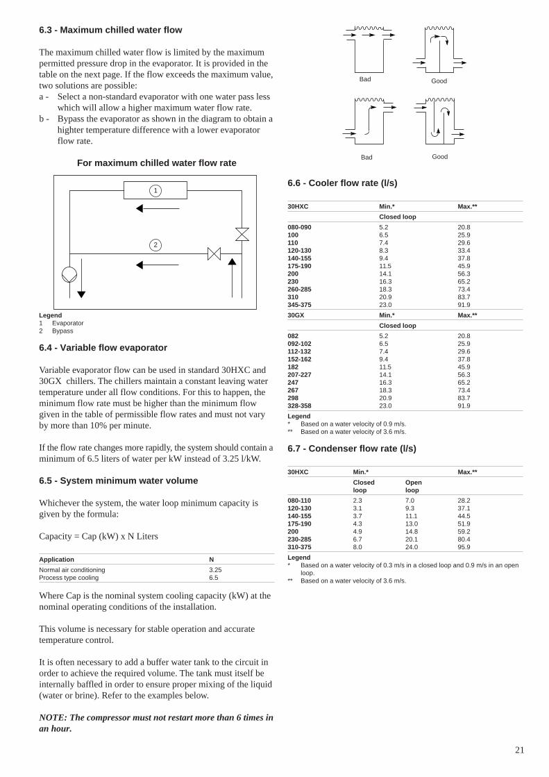
6.3 - Maximum chilled water flow
The maximum chilled water flow is limited by the maximumpermitted pressure drop in the evaporator. It is provided in thetable on the next page. If the flow exceeds the maximum value,two solutions are possible:a - Select a non-standard evaporator with one water pass less
which will allow a higher maximum water flow rate.b - Bypass the evaporator as shown in the diagram to obtain a
highter temperature difference with a lower evaporatorflow rate.
For maximum chilled water flow rate
Legend1 Evaporator2 Bypass
6.4 - Variable flow evaporator
Variable evaporator flow can be used in standard 30HXC and30GX chillers. The chillers maintain a constant leaving watertemperature under all flow conditions. For this to happen, theminimum flow rate must be higher than the minimum flowgiven in the table of permissible flow rates and must not varyby more than 10% per minute.
If the flow rate changes more rapidly, the system should contain aminimum of 6.5 liters of water per kW instead of 3.25 l/kW.
6.5 - System minimum water volume
Whichever the system, the water loop minimum capacity isgiven by the formula:
Capacity = Cap (kW) x N Liters
Application N
Normal air conditioning 3.25Process type cooling 6.5
Where Cap is the nominal system cooling capacity (kW) at thenominal operating conditions of the installation.
This volume is necessary for stable operation and accuratetemperature control.
It is often necessary to add a buffer water tank to the circuit inorder to achieve the required volume. The tank must itself beinternally baffled in order to ensure proper mixing of the liquid(water or brine). Refer to the examples below.
NOTE: The compressor must not restart more than 6 times inan hour.
6.6 - Cooler flow rate (l/s)
30HXC Min.* Max.**
Closed loop
080-090 5.2 20.8100 6.5 25.9110 7.4 29.6120-130 8.3 33.4140-155 9.4 37.8175-190 11.5 45.9200 14.1 56.3230 16.3 65.2260-285 18.3 73.4310 20.9 83.7345-375 23.0 91.9
30GX Min.* Max.**
Closed loop
082 5.2 20.8092-102 6.5 25.9112-132 7.4 29.6152-162 9.4 37.8182 11.5 45.9207-227 14.1 56.3247 16.3 65.2267 18.3 73.4298 20.9 83.7328-358 23.0 91.9
Legend* Based on a water velocity of 0.9 m/s.** Based on a water velocity of 3.6 m/s.
6.7 - Condenser flow rate (l/s)
30HXC Min.* Max.**
Closed Openloop loop
080-110 2.3 7.0 28.2120-130 3.1 9.3 37.1140-155 3.7 11.1 44.5175-190 4.3 13.0 51.9200 4.9 14.8 59.2230-285 6.7 20.1 80.4310-375 8.0 24.0 95.9
Legend* Based on a water velocity of 0.3 m/s in a closed loop and 0.9 m/s in an open
loop.** Based on a water velocity of 3.6 m/s.
Bad
Bad
Good
Good
1
2

22
6.8 - Evaporator pressure drop curveP
ress
ure
drop
, kP
a
Water flow rate, l/s
Legend1 30HXC 080-090 / 30GX 0822 30HXC 100 / 30GX 092-1023 30HXC 110 / 30GX 112-122-1324 30HXC 120-1305 30HXC 140-155 / 30GX 152-1626 30HXC 175-190 / 30GX 1827 30HXC 200 / 30GX 207-2278 30HXC 230 / 30GX 2479 30HXC 260-285 / 30GX 26710 30HXC 310 / 30GX 29811 30HXC 345-375 / 30GX 328-358
6.9 - Condenser pressure drop curve
5 30HXC 2006 30HXC 230-260-2857 30HXC 310-345-375
Pre
ssur
e dr
op, k
Pa
Water flow rate, l/s
Note:The dotted part of the curves corresponds to the flow values only permittedfor closed circuits.
Legend1 30HXC 080-090-100-1102 30HXC 120-1303 30HXC 140-1554 30HXC 175-190
10
100
1 2 3 4 10 20 30 40
40
20
100
30
200
8
50
1
2 3
4
5
67
8
9
10
11
1
10
100
1000
1 2 3 4 5 10 20 30 40 50 100
2
34
20
3040
200
300400
1
2 34 5 6 7

23
7.1.2 - 30HXC 200-285Control box
30HXC A B C D E ØH
Standard080-190 (315/400A) 56 25 4 863 314 10.5
Option 150/150A080-140 (315/400A) 56 25 4 863 314 10.5155-190 (630A) 68 32 6 880 307.5 12.5
30HXC A B C D E F G ØH
StandardCircuit A200-285 (400A) 56 25 4 841 314 1183 314 10.5Circuit B200-285 (250A) 39 23.5 4 811.5 324 - - 8.5
Option 150/150ACircuit A200-230 (400A) 56 25 4 841 314 1183 314 10.5260-285 (630A) 68 32 6 - - 1200 307.5 12.5Circuit B200-260 (250A) 39 23.5 4 811.5 324 - - 8.5285 (400A) 56 25 4 841 314 1183 314 10.5
7.1.3 - 30HXC 310-375Control box
Legend1 Main disconnect switchPE Earth connectionS Power supply cable section (see table "Recommended wire sections").
30HXC A B C D E F G ØH
StandardCircuit A310-375 (400A) 56 25 4 1492.6 314 1824 314 10.5Circuit B310-345 (400A) 56 25 4 1492.6 314 1824 314 10.5375 (630A) 68 32 6 1510 307.5 1841 307.5 12.5
Option 150/150ACircuit A310 (400A) 56 25 4 1492.6 314 1824 314 10.5345-375 (630A) 68 32 6 1510 307.5 1841 307.5 12.5Circuit B310-375 (630A) 68 32 6 1510 307.5 1841 307.5 12.5
NOTES:The 30HXC 080-190 and 30GX 082-182 units have only onepower connection point located at the main disconnectswitch.
Before connecting electric power cables, it is imperative tocheck the correct order of the 3 phases (L1 - L2 - L3).
Non-certified drawings.
Refer to the certified drawings supplied with the unit oravailable on request.
7 - ELECTRICAL CONNECTION
7.1 - Electrical connections 30HXC units
7.1.1 - 30HXC 080-190Control box

24
7.2.3 - 30GX 207-267Control box
7 - ELECTRICAL CONNECTION
7.2 - Electrical connections 30GX units
7.2.1 - 30GX 082-132Control box
NOTES:The 30HXC 080-190 and 30GX 082-182 units have only onepower connection point located at the main disconnectswitch.
Before connecting electric power cables, it is imperative tocheck the correct order of the 3 phases (L1 - L2 - L3).
Non-certified drawings.
Refer to the certified drawings supplied with the unit oravailable on request.
Legend1 Main disconnect switchPE Earth connectionS Power supply cable section (see table "Recommended wire sections").X Disconnect switch position referred to the unit sideY Control box position referred to the unit base
30GX X Y
082-102 764 680112-132 862 924
7.2.2 - 30GX 152-182Control box
30GX X Y
152-162 682 798182 912 1028
XY
X
Y
1758
1872

25
7.2.4 - 30GX 298-358Control box
NOTES:The 30HXC 080-190 and 30GX 082-182 units have only onepower connection point located at the main disconnectswitch.
Before connecting electric power cables, it is imperative tocheck the correct order of the 3 phases (L1 - L2 - L3).
Non-certified drawings.
Refer to the certified drawings supplied with the unit oravailable on request.
Legend1 Main disconnect switchPE Earth connectionS Power supply cable section (see table "Recommended wire sections").X Disconnect switch position referred to the unit sideY Control box position referred to the unit base
7.3 - Power supply
The power supply must conform to the specification on thechiller nameplate. The supply voltage must be within the rangespecified in the electrical data table. For connections refer tothe wiring diagrams.
WARNING: Operation of the chiller with an improper supplyvoltage or excessive phase imbalance constitutes abuse whichwill invalidate the Carrier warranty. If the phase imbalanceexceeds 2% for voltage, or 10% for current, contact yourlocal electricity supply at once and ensure that the chiller isnot switched on until corrective measures have been taken.
7.4 - Voltage phase imbalance (%)
100 x max. deviation from average voltageAverage voltage
Example:On a 400 V - 3 ph - 50 Hz supply, the individual phase voltageswere measured to be:
AB = 406 V ; BC = 399; AC = 394 V
Average voltage = (406 + 399 + 394)/3 = 1199/3= 399.7 say 400 V
Calculate the maximum deviation from the 400 V average:(AB) = 406 - 400 = 6(BC) = 400 - 399 = 1(CA) = 400 - 394 = 6
The maximum deviation from the average is 6 V. The greatestpercentage deviation is:
100 x 6/400 = 1.5 %
This is less than the permissible 2% and is therefore acceptable.
1758
1872

26
Electrical data notes for 30GX units:
• 30GX 082-182 units have a single power connection point; 30GX 207-358units have two connection points.
• The control box includes the following standard features:- Starter and motor protection devices for each compressor and the fan(s)- Control devices
• Field connections:All connections to the system and the electrical installations must be in fullaccordance with all applicable local codes.
• The Carrier 30GX units are designed and built to ensure conformance withthese codes. The recommendations of European standard EN 60 204-1(corresponds to IEC 60204-1) (machine safety - electrical machine compo-nents - part 1: general regulations) are specifically taken into account, whendesigning the electrical equipment.
• Electrical reserves:Circuit A has disconnect switches and branch sections, designed to supplythe evaporator pump power input.
IMPORTANT:• Generally the recommendations of IEC 60364 are accepted as compliance
with the requirements of the installation directives. Conformance with EN 60204 is the best means of ensuring compliance with the Machines Directive §1.5.1.
• Annex B of EN 60204-1 describes the electrical characteristics used for theoperation of the machines.
1. The operating environment for the 30GX units is specified below:a. Environment* - Environment as classified in EN 60 721 (corresponds to IEC
60721) :
Electrical data notes for 30HXC units:
• 30HXC 080-190 units have a single power connection point; 30HXC 200-375units have two connection points.
• The control box includes the following standard features:- Starter and motor protection devices for each compressor- Control devices
• Field connections:All connections to the system and the electrical installations must be in fullaccordance with all applicable codes.
• The Carrier 30HXC units are designed and built to ensure conformance withlocal codes. The recommendations of European standard EN 60204-1 (corre-sponds to IEC 60204-1) (machine safety - electrical machine components -part 1: general regulations) are specifically taken into account, when design-ing the electrical equipment.
• Electrical reserves:Circuit B has disconnect switches and branch sections, designed to supplythe evaporator and condenser pump power input.
IMPORTANT:• Generally the recommendations of IEC 60364 are accepted as compliance
with the requirements of the installation directives. Conformance with EN60204-1 is the best means of ensuring compliance with the MachinesDirective and § 1.5.1.
• Annex B of EN 60204-1 describes the electrical characteristics used for theoperation of the machines.
1. The operating environment for the 30HXC units is specified below:a. Environment* - Environment as classified in IEC 60364 § 3:- ambient temperature range: +5°C to +40°C, class AA4
- humidity range (non-condensing)*:50% relative humidity at 40°C90% relative humidity at 20°C
- altitude: ≤ 2000 m- indoor installation*- presence of water: class AD2* (possibility of water droplets)- presence of hard solids, class AE2* (no significant dust present)- presence of corrosive and polluting substances, class AF1 (negligible)- vibration and shock, class AG2, AH2b. Competence of personnel, class BA4* (trained personnel - IEC 60364)2. Power supply frequency variation: ± 2 Hz.3. The neutral (N) line must not be connected directly to the unit (if necessary
use a transformer).4. Overcurrent protection of the power supply conductors is not provided with
the unit.5. The factory-installed disconnect switch(es)/circuit breaker(s) is (are) of a type
suitable for power interruption in accordance with EN 60947 (corresponds toIEC 60947) .
6. The units are designed for connection to TN networks (IEC 60364). For ITnetworks the earth connection must not be at the network earth. Provide alocal earth, consult competent local organisations to complete the electricalinstallation.
NOTE: If particular aspects of an actual installation do not conform tothe conditions described above, or if there are other conditions whichshould be considered, always contact your local Carrier representative.
* The protection level required to conform to this class is IP21B (according to referencedocument IEC 60529). All 30HXC units are protected to IP23C and fulfil this protectioncondition.
- outdoor installation*- ambient temperature range: -18°C to +46°C, class 4K3*- altitude: ≤ 2000 m- presence of hard solids, class 4S2* (no significant dust present)- presence of corrosive and polluting substances, class 4C2 (negligible)- vibration and shock, class 4M2b. Competence of personnel, class BA4* (trained personnel - IEC 60364)2. Power supply frequency variation: ± 2 Hz.3. The neutral (N) line must not be connected directly to the unit (if necessary
use a transformer).4. Overcurrent protection of the power supply conductors is not provided with
the unit.5. The factory-installed disconnect switch(es)/circuit breaker(s) is (are) of a type
suitable for power interruption in accordance with EN 60947 (corresponds toIEC 60947) .
6. The units are designed for connection to TN networks (IEC 60364). For ITnetworks the earth connection must not be at the network earth. Provide alocal earth, consult competent local organisations to complete the electricalinstallation.
NOTE: If particular aspects of an actual installation do not conform tothe conditions described above, or if there are other conditions whichshould be considered, always contact your local Carrier representative.
* The required protection level for this class is IP43BW (according to reference documentIEC 60529). All 30GX units are protected to IP44CW and fulfil this protection condition.

27
7.5 - Recommended wire sections
Wire sizing is the responsibility of the installer, and depends onthe characteristics and regulations applicable to each installationsite. The following is only to be used as a guideline, and doesnot make Carrier in any way liable. After wire sizing has beencompleted, using the certified dimensional drawing, the instal-ler must ensure easy connection and define any modificationsnecessary on site.
The connections provided as standard for the field-suppliedpower entry cables to the general disconnect/isolator switchare designed for the number and type of wires, listed in thetable below.
The calculations are based on the maximum machine current(see electrical data tables).
For the design the following standardised installation methodsare used, in accordance with IEC 60364, table 52C:• For 30HXC units installed inside the building: No.13:
perforated horizontal cable conduit, and No. 41: closedconduit.
• For 30GX units installed outside the building: No.17:suspended aerial lines, and No. 61: buried conduit with aderating coefficient of 20.
The calculation is based on PVC or XLPE insulated cableswith copper or aluminium core. The maximum temperature is40°C for 30HXC units and 46°C for 30GX units.
The given wire length limits the voltage drop to < 5%.
IMPORTANT: Before connection of the main power cables(L1 - L2 - L3) on the terminal block, it is imperative to checkthe correct order of the 3 phases before proceeding to theconnection on then terminal block or the main disconnect/isolator switch.
7.5.1 - Field control wiringRefer to the 30GX/HXC Pro-Dialog Plus Controls IOM andthe certified wiring diagram supplied with the unit for the fieldcontrol wirting of the following features:• Evaporator pump interlock (mandatory)• Remote on/off switch• Condenser flow switch (field-supplied, 30HXC only)• Remote heat/cool switch• Demand limit external switch 1• Remote dual set point• Alarm report by circuit• Evaporator pump control• Condenser pump control (30HXC only)• Remote set point reset or outside air temperature sensor
reset (0-10 V)
7.5.2 - Selection table of minimum and maximum wire sections for connection to 30HXC units
400 V-3 ph-50 Hz
30HXC Minimum wire Maximum wiresection (mm2) Wire type L (m) section (mm2) Wire type L (m)
080 1 x 50 XLPE Cu 160 1 x 120 XLPE Al 205090 1 x 50 XLPE Cu 160 1 x 120 XLPE Al 205100 1 x 70 XLPE Cu 170 1 x 150 XLPE Al 210110 1 x 70 XLPE Cu 170 1 x 185 XLPE Al 220120 1 x 95 XLPE Cu 180 1 x 185 XLPE Al 220130 1 x 95 XLPE Cu 180 1 x 240 XLPE Al 225140 1 x 120 XLPE Cu 185 2 x 95 XLPE Al 195155 1 x 120 XLPE Cu 185 2 x 120 XLPE Al 205175 1 x 150 XLPE Cu 190 2 x 120 XLPE Al 205190 1 x 185 XLPE Cu 190 2 x 150 XLPE Al 210200 Circuit A 1 x 95 XLPE Cu 180 1 x 185 XLPE Al 220
1 x 120 XLPE Cu 225230 Circuit A 1 x 95 XLPE Cu 180 1 x 240 XLPE Al 225
1 x 150 XLPE Cu 230260 Circuit A 1 x 120 XLPE Cu 185 2 x 150 XLPE Al 265
1 x 240 XLPE Cu 235285 Circuit A 1 x 150 XLPE Cu 190 2 x 185 XLPE Al 270
2 x 120 XLPE Cu 280310 Circuit A 1 x 120 XLPE Cu 185 2 x 120 XLPE Al 255
2 x 95 XLPE Cu 270345 Circuit A 1 x 120 XLPE Cu 185 2 x 150 XLPE Al 265
2 x 95 XLPE Cu 270375 Circuit A 1 x 150 XLPE Cu 190 2 x 185 XLPE Al 270
2 x 120 XLPE Cu 280200 Circuit B 1 x 50 XLPE Cu 160 1 x 120 XLPE Al 205
1 x 70 XLPE Cu 205230 Circuit B 1 x 70 XLPE Cu 170 1 x 150 XLPE Al 210
1 x 95 XLPE Cu 215260 Circuit B 1 x 95 XLPE Cu 180 1 x 150 XLPE Al 210
1 x 95 XLPE Cu 215285 Circuit B 1 x 95 XLPE Cu 180 1 x 185 XLPE Al 220
1 x 120 XLPE Cu 225310 Circuit B 1 x 185 XLPE Cu 190 2 x 185 XLPE Al 270
1 x 240 XLPE Cu 235345 Circuit B 1 x 185 XLPE Cu 190 2 x 185 XLPE Al 270
2 x 120 XLPE Cu 280375 Circuit B 1 x 240 XLPE Cu 190 2 x 240 XLPE Al 280
2 x 150 XLPE Cu 290
S Power supply wire section (see diagram in chapter ‘Electrical connection’).

28
7.5.3 - Selection table of minimum and maximum wire sections for connection to 30HXC units with high condensingtemperatures (option 150 + 150A)
400 V-3 ph-50 Hz
30HXC Minimum wire Maximum wiresection (mm2) Wire type L (m) section (mm2) Wire type L (m)
080 Opt. 150 1 x 70 XLPE Cu 170 1 x 150 XLPE Al 210090 Opt. 150 1 x 70 XLPE Cu 170 1 x 185 XLPE Al 220100 Opt. 150 1 x 95 XLPE Cu 180 1 x 240 XLPE Al 225110 Opt. 150 1 x 95 XLPE Cu 180 1 x 240 XLPE Al 225120 Opt. 150 1 x 120 XLPE Cu 185 2 x 95 XLPE Al 195130 Opt. 150 1 x 120 XLPE Cu 185 2 x 120 XLPE Al 205140 Opt. 150 1 x 150 XLPE Cu 190 2 x 120 XLPE Al 205155 Opt. 150 1 x 185 XLPE Cu 190 2 x 150 XLPE Al 210175 Opt. 150 1 x 185 XLPE Cu 190 2 x 150 XLPE Al 210190 Opt. 150 2 x 95 XLPE Cu 170 2 x 240 XLPE Al 225200 Opt. 150 Circuit A 1 x 120 XLPE Cu 185 2 x 150 XLPE Al 265
1 x 185 XLPE Cu 235230 Opt. 150 Circuit A 1 x 150 XLPE Cu 190 2 x 150 XLPE Al 265
1 x 240 XLPE Cu 235260 Opt. 150 Circuit A 1 x 185 XLPE Cu 190 2 x 240 XLPE Al 280
2 x 150 XLPE Cu 290285 Opt. 150 Circuit A 1 x 240 XLPE Cu 190 2 x 240 XLPE Cu 295310 Opt. 150 Circuit A 1 x 150 XLPE Cu 190 2 x 185 XLPE Al 270
2 x 120 XLPE Cu 280345 Opt. 150 Circuit A 1 x 185 XLPE Cu 190 2 x 240 XLPE Al 280
2 x 150 XLPE Cu 290375 Opt. 150 Circuit A 1 x 240 XLPE Cu 190 2 x 240 XLPE Cu 295200 Opt. 150 Circuit B 1 x 70 XLPE Cu 170 1 x 150 XLPE Al 210
1 x 95 XLPE Cu 215230 Opt. 150 Circuit B 1 x 70 XLPE Cu 170 1 x 185 XLPE Al 220
1 x 120 XLPE Cu 225260 Opt. 150 Circuit B 1 x 70 XLPE Cu 170 1 x 185 XLPE Al 220
1 x 120 XLPE Cu 225285 Opt. 150 Circuit B 1 x 120 XLPE Cu 185 2 x 150 XLPE Al 265
1 x 185 XLPE Cu 235310 Opt. 150 Circuit B 1 x 185 XLPE Cu 190 2 x 240 XLPE Al 280
2 x 150 XLPE Cu 290345 Opt. 150 Circuit B 1 x 240 XLPE Cu 190 2 x 240 XLPE Al 280
2 x 150 XLPE Cu 290375 Opt. 150 Circuit B 2 x 95 XLPE Cu 170 2 x 240 XLPE Cu 295
S Power supply wire section (see diagram in chapter ‘Electrical connection’).
7.5.4 - Selection table of minimum and maximum wire sections for connection to 30GX units
400 V-3 ph-50 Hz
30GX Minimum wire Maximum wiresection (mm2) Wire type L (m) section (mm2) Wire type L (m)
082 1 x 95 XLPE Cu 190 2 x 240 PVC Al 450092 1 x 120 XLPE Cu 195 2 x 240 PVC Al 450102 1 x 120 XLPE Cu 195 2 x 185 PVC Cu 470112 1 x 150 XLPE Cu 200 2 x 240 PVC Cu 480122 1 x 185 XLPE Cu 205 2 x 240 PVC Cu 480132 1 x 185 XLPE Cu 205 3 x 240 XLPE Cu 355152 1 x 240 XLPE Cu 205 3 x 240 PVC Cu 600162 1 x 240 XLPE Cu 205 3 x 185 XLPE Cu 430182 2 x 120 XLPE Cu 200 3 x 240 XLPE Cu 440207 (Circuit A) 1 x 185 XLPE Cu 205 3 x 240 PVC Cu 685227 (Circuit A) 1 x 240 XLPE Cu 205 3 x 185 XLPE Cu 490247 (Circuit A) 1 x 240 XLPE Cu 205 3 x 240 XLPE Cu 505267 (Circuit A) 2 x 120 XLPE Cu 200 3 x 240 XLPE Cu 505298 (Circuit A) 2 x 95 XLPE Cu 190 3 x 240 XLPE Cu 505328 (Circuit A) 2 x 95 XLPE Cu 190 3 x 240 XLPE Cu 505358 (Circuit A) 2 x 120 XLPE Cu 200 3 x 240 XLPE Cu 505207/227/247 (Circuit B) 1 x 95 XLPE Cu 190 2 x 240 PVC Al 560
2 x 95 XLPE Cu 380267 (Circuit B) 1 x 120 XLPE Cu 195 2 x 240 XLPE Al 410
2 x 150 XLPE Cu 415298 (Circuit B) 1 x 185 XLPE Cu 205 3 x 240 PVC Cu 685328 (Circuit B) 1 x 240 XLPE Cu 205 3 x 185 XLPE Cu 490358 (Circuit B) 2 x 120 XLPE Cu 200 3 x 240 XLPE Cu 505
S Power supply wire section (see diagram in chapter ‘Electrical connection’).

29
8 - WATER CONNECTIONS
ATTENTION: Before carrying out any water connectionsinstall the water box purge plugs (one plug per water box inthe lower section - supplied in the control box).
For size and position of the heat exchanger water inlet andoutlet connections refer to the certified dimensional drawingssupplied with the unit.
The water pipes must not transmit any radial or axial force tothe heat exchangers nor any vibration.
The water supply must be analysed and appropriate filtering,treatment, control devices, isolation and bleed valves andcircuits built in, to prevent corrosion, fouling and deteriorationof the pump fittings. Consult either a water treatment specialistor appropriate literature on the subject.
8.1 - Operating precautions
The water circuit should be designed to have the least numberof elbows and horizontal pipe runs at different levels. Belowthe main points to be checked for the connection:• Comply with the water inlet and outlet connections shown
on the unit.• Install manual or automatic air purge valves at all high
points in the circuit(s).• Use an expansion device to maintain pressure in the
circuit(s) and install a safety valve as well as an expansiontank.
• Install thermometers in both the entering and leavingwater connections.
• Install drain connections at all low points to allow thewhole circuit to be drained.
• Install stop valves, close to the entering and leaving waterconnections.
• Use flexible connections to reduce the transmission ofvibrations.
• Insulate all pipework, after testing for leaks, both toreduce heat gains and to prevent condensation.
• Cover the insulation with a vapour barrier.• Where there are particles in the fluid that could foul the
heat exchanger, a screen filter should be installed ahead ofthe pump. The mesh size of the filter must be 1.2 mm (see‘Typical water circuit’ diagram on the right).
• Before the system start-up verify that the water circuits areconnected to the appropriate heat exchangers (e.g. noreversal between evaporator and condenser).
• Do not introduce any significant static or dynamicpressure into the heat exchange circuit (with regard to thedesign operating pressures).
• Before any start-up verify that the heat exchange fluid iscompatible with the materials and the water circuitcoating.
In case additives or other fluids than those recommendedby Carrier SCS are used, ensure that the fluids are notconsidered as a gas, and that they belong to class 2, asdefined in directive 97/23/EC.
Carrier SCS recommendations on heat exchange fluids:1. No NH4+ ammonium ions in the water, they are very
detrimental for copper. This is one of the most importantfactors for the operating life of copper piping. A contentof several tenths of mg/l will badly corrode the copperover time.
2. Cl- Chloride ions are detrimental for copper with a risk ofperforations by corrosion by puncture. If possible keepbelow 10 mg/l.
3. SO42- sulphate ions can cause perforating corrosion, if
their content is above 30 mg/l.4. No fluoride ions (<0.1 mg/l).5. No Fe2+ and Fe3+ ions with non negligible levels of
dissolved oxygen must be present. Dissolved iron < 5 mg/lwith dissolved oxygen < 5 mg/l.
6. Dissolved silicon: silicon is an acid element of water andcan also lead to corrosion risks. Content < 1mg/l.
7. Water hardness: TH >2.8 F. Values between 10 and 25can be recommended. This will facilitate scale deposit thatcan limit corrosion of copper. TH values that are too highcan cause piping blockage over time. A total alkalimetrictitre (TAC) below 100 is desirable.
8. Dissolved oxygen: Any sudden change in water oxygen-ation conditions must be avoided. It is as detrimental todeoxygenate the water by mixing it with inert gas as it isto over-oxygenate it by mixing it with pure oxygen. Thedisturbance of the oxygenation conditions encouragesdestabilisation of copper hydroxides and enlargement ofparticles.
9. Specific resistance – electric conductivity: the higher thespecific resistance, the slower the corrosion tendency.Values above 3000 Ohm/cm are desirable. A neutralenvironment favours maximum specific resistance values.For electric conductivity values in the order of 200-6000S/cm can be recommended.
10. pH: Ideal case pH neutral at 20-25°C7 < pH < 8
If the water circuit must be emptied for longer than one month,the complete circuit must be placed under nitrogen charge toavoid any risk of corrosion by differential aeration.
Charging and removing heat exchange fluids should be donewith devices that must be included on the water circuit by theinstaller. Never use the unit heat exchangers to add heatexchange fluid.

30
Potentiometer adjustment
Legend1 Setting potentiometer sensitivity2 Chain of LEDs
- red LED lights: the unit is not adjusted- yellow LED lights: the output is switched- green LED lights: the unit is adjusted
8.3.2 - Condenser water flow switch (30HXC)The use of a condenser water flow switch is recommended. Theflow switch is not supplied, and must be installed on site andconnected in accordance with the wiring diagrams.
8.4 - Evaporator (and condenser for the 30HXC) waterbox bolt tightening
The evaporator (and condenser) are of the shell and tube typewith removable water boxes to facilitate cleaning. Re-tighten-ing or tightening must be done in accordance with the illustra-tion below.
Water box tightening sequence
Legend1 Sequence 1: 1 2 3 4
Sequence 2: 5 6 7 8Sequence 3: 9 10 11 12
2 Tightening torqueBolt size M16 - 171 - 210 Nm
8.2 - Water connections
This diagram shows a typical water installation.
Typical water circuit diagram
Legend1 Control valve2 Air vent3 Flow switch for the evaporator4 Flexible connection5 Heat exchanger6 Pressure tap7 Thermostat sleeve8 Drain9 Buffer tank10 Filter (mesh size: 1.2 mm = 20 mesh)11 Expansion tank12 Fill valve
8.3 - Flow control
8.3.1 - Evaporator flow switch and chilled water pumpinterlock
IMPORTANT: On 30GX and 30HXC units, the unit waterflow switch must be energised, and the chilled water pumpinterlock must be connected. Failure to follow this instructionwill void the Carrier guarantee.
The flow switch is supplied, installed on the evaporatorentering water pipe and preset at the factory to cut out whenthere is insufficient water flow. If adjustment is necessary:1. Switch on the unit. Set it to constant flow (preset value).
The yellow LED is illuminated, and the output is switchedfor approximately 20 seconds (power-on delay time).
2. Turn the potentiometer until one green LED is illuminated.
The further the green LED is from the yellow LED, thesafer the adjustment (standby capacity in case of flow ortemperature fluctuations).
3. After the adjustment attach the label supplied to thepotentiometer, in order to protect it against unauthorisedtampering.
Terminals 34 and 35 are provided for field installation of thechilled water pump interlock (auxiliary contact for pumpoperation to be wired on site).
2
1
1 2
3
4 5
6
78
9
1011
12

31
NOTE: Before this operation we recommend draining thecircuit and disconnecting the pipes to be sure that the boltsare correctly and uniformly tightened.
8.5 - Frost protection
8.5.1 - Standard machineIf the chiller or the water piping is in an area where the ambienttemperature can fall below 0°C it is recommended to add anantifreeze solution to protect the unit and the water piping to atemperature of 10 K below the lowest temperature likely to bereached at the installation site. Use only antifreeze solutions,approved for heat exchanger duty. If the system is not protectedby an antifreeze solution and will not be used during the freezingweather conditions, draining of the cooler and outdoor piping ismandatory. Damage due to freezing is not covered by thewarranty.
IMPORTANT: Depending on the climatic conditions in yourarea you must:- Add ethylene glycol with an adequate concentration to
protect the installation up to a temperature of 10 K belowthe lowest temperature likely to occur at the installationsite.
- If the unit is not used for an extended period, it isrecommended to drain it, and as a safety precaution addethylene glycol to the heat exchanger, using the waterentering purge valve connection (a purge connection isavailable somewhere on the heat exchanger water box incase the machine is not perfectly level).
At the start of the next season, refill the unit with waterand add an inhibitor.
- For the installation of auxiliary equipment, the installermust comply with basic regulations, especially forminimum and maximum flow rates, which must bebetween the values listed in the operating limit table(application data).
8.5.2 - Optional evaporator frost protection (30GX)In cases where it is not possible to apply the recommendationsin paragraph 8.5.1, the units can be equipped with heaters toprotect the evaporator against frost (option 41A). See chapter10.4 “Evaporator frost protection (30GX)”.
8.6 - Operation of two units in master/slave mode
The control of a master/slave assembly is in the entering waterand does not require any additional sensors (standard configu-ration). It can also be located in the leaving water. In this casetwo additional sensors must be added on the common piping.
All parameters, required for the master/slave function must beconfigured using the Service Configuration menu. All remotecontrols of the master/slave assembly (start/stop, set point, loadshedding etc.) are controlled by the unit configured as master andmust only be applied to the master unit.
Each unit controls its own water pump. If there is only onecommon pump, in cases with variable flow, isolation valvesmust be installed on each unit. They will be activated at theopening and closing by the control of each heat pump (in thiscase the valves are controlled using the dedicated water pumpoutputs). See the 30GX/HXC Pro-Dialog Plus Control IOM fora more detailed explanation.
30HXC/GX WITH CONFIGURATION: LEAVING WATER CONTROL
Legend
1 Master unit2 Slave unit
Control boxes of the master and slave units
Water inlet
Water outlet
Water pumps for each unit (included as standard for units with hydronic
module)Additional sensors for leaving water control, to be connected to channel 1 ofthe slave boards of each master and slave unitCCN communication busConnection of two additional sensors
1 2

32
9 - MAJOR SYSTEM COMPONENTS ANDOPERATION DATA
9.1 - Geared twin screw compressor
• 30HXC and 30GX units use 06N geared twin screwcompressors
• 06NA are used on 30GX (air-cooled condensing applica-tion)
• 06NW are used on 30HXC (water-cooled condensingapplication)
• Nominal capacities range from 39 to 80 tons. Economizedor non economized models are used depending on the30HXC and 30GX unit size.
9.1.1 - Oil filterThe 06N screw compressor has an oil filter integral in thecompressor housing. This filter is field replaceable.
9.1.2. - RefrigerantThe 06N screw compressor is specially designed to be used inR134 a system only.
9.1.3 - LubricantThe 06N screw compressor is approved for use with thefollowing lubricant:
CARRIER MATERIAL SPEC PP 47-32
9.1.4 - Oil supply solenoid valveAn oil supply solenoid valve is standard on the compressor toisolate the compressor from oil flow when the compressor isnot operating.
The oil solenoid is field replaceable.
9.1.5 - Suction and economizer screensTo increase the reliability of the compressor, a screen has beenincorporated as a standard feature into suction and economizerinlets of the compressor.
9.1.6 - Unloading systemThe 06N screw compressor has an unloading system that isstandard on all compressors. This unloading system consists oftwo steps of unloading that decrease the compressor capacityby rerouting partially compressed gas back to suction.
9.2 - Pressure vessels
9.2.1 - Evaporator30HXC and 30GX chillers use a flooded evaporator. The watercirculates in the tubes and the refrigerant is on the outside inthe shell. One vessel is used to serve both refrigerant circuits.There is a center tube sheet which separates the two refrigerantcircuits. The tubes are 3/4" diameter copper with an enhancedsurface inside and out. There is just one water circuit, anddepending on the size of the chiller, there may be two or threewater passes.
At the top of the cooler are the two suction pipes, one in eachcircuit. Each has a flange welded to it, and the compressormounts on the flange.
The evaporator shell has a thermal insulation of 19 mm thickpolyurethane foam and a water drain and purge. With the verylow temperature option this insulation is 38 mm thick.
9.2.2 - Condenser and oil separator (30HXC)30HXC chiller use a vessel that is a combination condenser andoil separator. It is mounted below the cooler. Discharge gasleaves the compressor and flows through an external muffler tothe oil separator, which is the upper portion of the vessel. Itenters the top of the separator where oil is removed, and thenflows to the bottom portion of the vessel, where gas is condensedand subcooled. One vessel is used to serve both refrigerantcircuits. There is a center tube sheet which separates the tworefrigerant circuits. The tubes are 3/4" or 1" diameter copperwith enhanced surface inside and out. There is just one watercircuit with two water passes.
The condenser shell can have a thermal insulation of 19 mmthick polyurethane foam and a water drain and purge.
9.2.3 - Oil separator (30GX)In the air-cooled units, the oil separator is a pressure vessel thatis mounted under the outside vertical condenser coils. Dischargegas enters at the top of the separator where much of the oilseparates and drains to the bottom. The gas then flows througha wire mesh screen where the remaining oil is separated anddrains to the bottom.
The oil separator vessel shell has a thermal insulation of 19 mmthick polyurethane foam.
The oil separator is equipped with a trace heater regulated bythe control. This heater is equipped with an internal thermostatthat disconnects the power supply when the temperaturereaches 85°C and automatically resets when the temperatureagain falls to a normal value.
The products that may be added for thermal insulation of thevessels during the water piping connection procedure must bechemically neutral in relation to the materials and coatings towhich they are applied. This is also the case for the productsoriginally supplied by Carrier SCS.

33
9.3 - Electronic expansion device (EXV)
The microprocessor controls the EXV through the EXV controlmodule. Inside this EXV is a linear actuator stepper motor.High-pressure liquid refrigerant enters the valve through thebottom. A series of calibrated slots are located inside the orificeassembly. As refrigerant passes through the orifice, the pressuredrops and the refrigerant changes to a 2-phase condition (liquidand vapor). To control refrigerant flow for different operatingconditions, the sleeve moves up and down over the orifice,thereby changing effective flow area of expansion device. Thesleeve is moved by a linear stepper motor. The stepper motormoves in increments and is controlled directly by the processormodule. As the stepper motor rotates, motion is transferred intolinear movement by the lead screw. Through the stepper motorand lead screws, 1500 discrete steps of motion are obtained.The large number of steps and long stroke result in veryaccurate control of refrigerant flow. At initial start-up, the EXVposition is at zero. After that, the microprocessor keeps accuratetrack of the valve position in order to use this information asinput for the other control functions. It does this by initializingthe EXV’s at startup. The processor sends out enough closingpulses to the valve to move it from fully open to fully closed,then resets the position counter to zero. From this point on,until the initialization, the processor counts the total number ofopen and closed steps it has sent to each valve.
9.4 - Economizer
Economizers are installed on 30HXC 190, 285 and 375 and30GX 182, 267 and 358.
The economizer improves both the chiller capacity and effi-ciency as well as providing motor cooling. The economizersused are direct-expansion plate heat exchangers.
The flow of the direct-expansion plate heat exchanger circuit isadjusted by the motor cooling valves. The circuit permits sub-cooling of the liquid circuit.
9.5 - Oil pumps
The 30GX/HXC screw chillers use one externally mountedpre-lubricating oil pump per circuit. This pump is operated aspart ot the start-up sequence.
ATTENTION: The operating temperature of the coil mayreach 80°C. In certain temporary conditions (especiallyduring start-up at low outside temperature or low condenserloop temperature) the oil pump can be reactivated.
On 30GX units, the pumps are mounted to the base rails on theoil separator side of the unit. The pumps are mounted to abracket on the condensers of 30HXC units. When a circuit isrequired to start, the controls will energize the oil pump first sothat the compressor starts with correct lubrication. If the pumphas built up sufficient oil pressure, the compressor will beallowed to start. Once the compressor has started, the oil pumpwill be turned off. If the pump was not able to build up enoughoil pressure, the control will generate an alarm.
NOTES: Monitoring during operation, re-qualification, re-testing and re-testing dispensation:- Follow the regulations on monitoring pressurised
equipment.- It is normally required that the user or operator sets up
and maintains a monitoring and maintenance file.- Follow the control programmes of EN 378-2, annexes A,
B, C and D.- If they exist follow local professional recommendations.- Regularly inspect the condition of the coating (paint) to
detect blistering resulting from corrosion. To do this,check a non-insulated section of the container or therust formation at the insulation joints.
- Regularly check for possible presence of impurities (e.g.silicon grains) in the heat exchange fluids. These impuri-ties maybe the cause of the wear or corrosion by puncture.
- Filter the heat exchange fluid check and carry outinternal inspections as described in EN 378-2, annex C.
- In case of re-testing take the possible maximum pressuredifference of 25 bar into consideration.
- The reports of periodical checks by the user or operatormust be included in the supervision and maintenancefile.
RepairAny repair or modification, including the replacement ofmoving parts:- must follow local regulations and be made by qualified
operators and in accordance with qualified procedures,including changing the heat exchanger tubes
- must be made in accordance with the instructions of theoriginal manufacturer. Repair and modification thatnecessitate permanent assembly (soldering, welding,expanding etc.) must be made using the correctprocedures and by qualified operators.
- An indication of any modification or repair must beshown in the monitoring and maintenance file.
RecyclingThe unit is wholly or partly recyclable. After use it containsrefrigerant vapours and oil residue. It is coated by paint.
Operating lifeThis unit is designed for:- prolonged storage of 15 years under nitrogen charge
with a temperature difference of 20 K per day.- 452000 cycles (start-ups) with a maximum difference of
6 K between two neighbouring points in the vessel, basedon 6 start-ups per hour over 15 years at a usage rate of57%.
Corrosion allowances:Gas side: 0 mmHeat exchange fluid side: 1 mm for tubular plates in lightlyalloyed steels, 0 mm for stainless steel plates or plates withcopper-nickel or stainless steel protection.
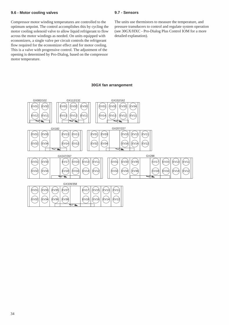
34
30GX fan arrangement
9.7 - Sensors
The units use thermistors to measure the temperature, andpressure transducers to control and regulate system operation(see 30GX/HXC - Pro-Dialog Plus Control IOM for a moredetailed explanation).
9.6 - Motor cooling valves
Compressor motor winding temperatures are controlled to theoptimum setpoint. The control accomplishes this by cycling themotor cooling solenoid valve to allow liquid refrigerant to flowacross the motor windings as needed. On units equipped witheconomizers, a single valve per circuit controls the refrigerantflow required for the economizer effect and for motor cooling.This is a valve with progressive control. The adjustment of theopening is determined by Pro-Dialog, based on the compressormotor temperature.
EV31
EV14 EV13
EV32 EV33
EV12 EV11
EV34EV31
EV13 EV12
EV32 EV33
EV11
EV31
EV12 EV11
EV32
EV13 EV13
EV13
EV14 EV14
EV14
EV31 EV33
EV33 EV37
EV32 EV34
EV34 EV38
EV34 EV36
EV36
EV32
EV32
EV33 EV35
EV35
EV31
EV31
EV17 EV17
EV17
EV18 EV18
EV18
EV15 EV15
EV15
EV16 EV16
EV16
EV11 EV11
EV11
EV12 EV12
EV12
EV11 EV11
EV12 EV12
EV13 EV13
EV14 EV14
EV15
EV16
EV31 EV31
EV32 EV32EV34 EV34
EV33 EV33
GX082/102 GX112/132 GX152/162
GX182 GX207/227
GX247/267 GX298
GX328/358

35
10 - MAIN OPTIONS AND ACCESSORIES
Depending on the applications for which the units are selected,they can be equipped with options. This chapter describes themain components that require special information for correctstart-up and maintenance of these units, except where this iscontained in a separate document.
10.1 - Compressor suction valves (option 92)
These valves are designed to isolate the compressor from therest of the circuit. Discharge valves, oil valves and coolingvalves are installed in the standard unit. A label attached to theevaporator near each valve shows the open or closed positionof the valve. It is important to remove the cap in order tomanoeuvre the valve shaft and to replace it after this operationto ensure leak-tightness.
10.2 - Compressor and evaporator noise insulation(30GX - option 14A)
The evaporator and the compressor body are wrapped in a noise-absorbing cover, consisting of a leak-tight enclosure, protectinga flexible acoustic material. It is fixed with self-adhesive tapeto the components. During maintenance operations certainparts must be removed, and later replaced. Take care to avoiddamage the leak-tight enclosure of the acoustic material and theelectrical connections.
10.3 - Low-noise 30GX units equipped with acousticpanels (option 15)
The modifications compared with the standard units are:• Factory-installation of an acoustic board• Factory-installation of side panels.• Field-installation of a fixing system for the acoustic panels.• Field-installation of removable acoustic panels
These units have a special dimensional drawing. The mountinginstructions are supplied with the panel fixing system.Following these instructions will:• facilitate installation• identify the position of each panel• identify the panel(s) behind which the control box is located• permit connection of a service tool linked to CCN without
removing the panels.
10.4 - Evaporator frost protection (30GX - option 41A)
The modifications compared with the standard units are:• additional solenoid valves at the condenser entering piping• additional liquid solenoid valves at the evaporator entering
refrigerant piping• additional heaters on the shell and the evaporator water
heads (under the insulation).
These elements can be shown on the unit and on the wiringdiagram.
When the unit stops, the closure of the solenoid valves preventsmigration of the refrigerant contained in the evaporator to thecondenser, if this is the cold point of the circuit. The heaters areactivated, when the outdoor temperature is low and permitmaintaining a saturated pressure in the evaporator (see 30GX/HXC Pro-Dialog Plus Control IOM for a more detailedexplanation).
Heater capacities 30GX units
30GX Capacity in kW
082-132 4.3152-162 4.8182 5.3207-227 5.8247-358 6.9
IMPORTANT: To ensure that the protection works the heatersand the control must be energised. The correct operation ofthe heaters must be verified at start-up and must form part ofthe annual operation checks of these units.
Never switch off the heaters. The main disconnect switch(QS101) and the auxiliary heater disconnect switch mustalways remain energised (see wiring diagram for location ofQS and QF101).
10.5 - Year-round operation of 30GX units (option 28)
The modifications compared with the standard units consist ofplacing insulated trace heaters on:• the oil piping• the oil filter box body
These elements can be shown on the unit and on the wiringdiagram.
The heaters are activated, based on the outdoor temperature(see 30GX/HXC Pro-Dialog Plus Control IOM for a moredetailed explanation).
The heaters are equipped with an internal thermostat thatdisconnects the power supply when the temperature reaches85°C and automatically resets when the temperature again fallsto a normal value.
10.6 - Soft Start for 3- and 4-compressor 30HXC and30GX units (option 25)
These units are equipped with an electronic compressor starter.This permits optimising the start-up current, and reducingnuisance cut-outs due to current surges in the electrical systemat start-up. The starter parameters are factory-set.
For more detailed information refer to the specific documentsupplied with this option.
IMPORTANT: If any work is carried out on the electricalcomponents, normal safety measures must be observed.Factory settings must not be modified. If these instructionsare not followed, the Carrier guarantee will become invalid.

36
11 - MAINTENANCE
11.1 - Maintenance instructions
During the unit operating life the service checks and tests mustbe carried out in accordance with applicable national regulations.
If there are no similar criteria in local regulations, the informationon checks during operation in annex C of standard EN 378-2can be used.
External visual checks: annex D of standard EN 378-2. Thesecontrols must be carried out:- After an intervention that is likely to affect the resistance
or a change in use or change of high-pressure refrigerant,or after a shut down of more than two years. Componentsthat do not comply, must be changed. Test pressuresabove the respective component design pressure must notbe applied (annex B and D).
- After repair or significant modifications or significantsystem or component extension (annex B)
- After re-installation at another site (annexes A, B and D)- After repair following a refrigerant leak (annex D). The
frequency of refrigerant leak detection can vary from onceper year for systems with less than 1% leak rate per yearto once a day for systems with a leak rate of 35% per yearor more. The frequency is in proportion with the leak rate.
NOTE: High leak rates are not acceptable. The necessarysteps must be taken to eliminate any leak detected.
NOTE 2: Fixed refrigerant detectors are not leak detectors,as they cannot locate the leak.
11.2 - Soldering and welding
Component, piping and connection soldering and weldingoperations must be carried out using the correct procedures andby qualified operators. Pressurised containers must not besubjected to shocks, nor to large temperature variations duringmaintenance and repair operations.
11.3 - Refrigerant charging - adding charge
IMPORTANT: These units are designed for use with R-134aonly. DO NOT USE ANY OTHER refrigerant in these units.
CAUTION: When adding or removing charge, circulatewater through the condenser (HX) and cooler at all times toprevent freezing. Freezing damage is considered abuse andmay void the Carrier warranty.
All refrigerant removal and draining operations must becarried out by a qualified technician and with the correctmaterial for the unit. Any inappropriate handling can lead touncontrolled fluid or pressure leaks.
CAUTION: DO NOT OVERCHARGE system. Overchargingresults in higher discharge pressure with higher cooling fluidconsumption, possible compressor damage and higher powerconsumption.
10.7 - Electric protection level of the 30HXC controlboxes to IP44C (option 20)
The control boxes are leak-tight and equipped with a ventilationsystem to ensure cooling of the electrical components. Thecontrol box fan is controlled by a thermostat (setpoint 55°C,differential 20°C). A safety thermostat switches the unit off, ifthe control box temperature exceeds 60°C.
These elements can be shown on the unit and on the wiringdiagram.
10.8 - Tropicalised control box for 30HXC and 30GXunits (option 22)
The control boxes are leak-tight and equipped with heaters.The standard components are already treated for “all-weather”operation. Heating the air will reduce the moisture level in thecontrol box and prevent condensation.
10.9 - Brine units for low-temperature evaporatorleaving applications (option 5)
These units are verified for compatibility between unit andspecific application.
They have control configuration parameters that are matched tothe application (see 30GX/HXC Pro-Dialog Plus Control IOMfor a more detailed explanation).
10.10 - Disassembled 30HXC units (option 52)
These units are equipped with flange connections on therefrigerant piping to permit disassembly of the units withoutunwelding. The dimensional drawing for this option gives theweight of the different parts. The units are fully factory-assembled, charged with oil and refrigerant and run-tested atthe end of the assembly line. The refrigerant charge is thenremoved and replaced by a nitrogen holding charge.
IMPORTANT: The oil charge remains in the unit and mustnot be exposed to moisture during disassembly and reassembly.The refrigerant charge is not supplied and must be providedon site. Please refer to the unit nameplate.
10.11 - Available fan pressure of 150 Pa for 30GXunits (option 12)
The electrical section and the fan disconnect switches arematched to the application. The relevant certified dimensionaldrawing shows the new elements (unit weights and dimensions,duct connection diameters and location).
IMPORTANT: The units (supplied for operation withdischarge ducts) are shipped without fan discharge protectiongrilles. For safety reasons, the unit must not be started untilthe ducts have been connected.
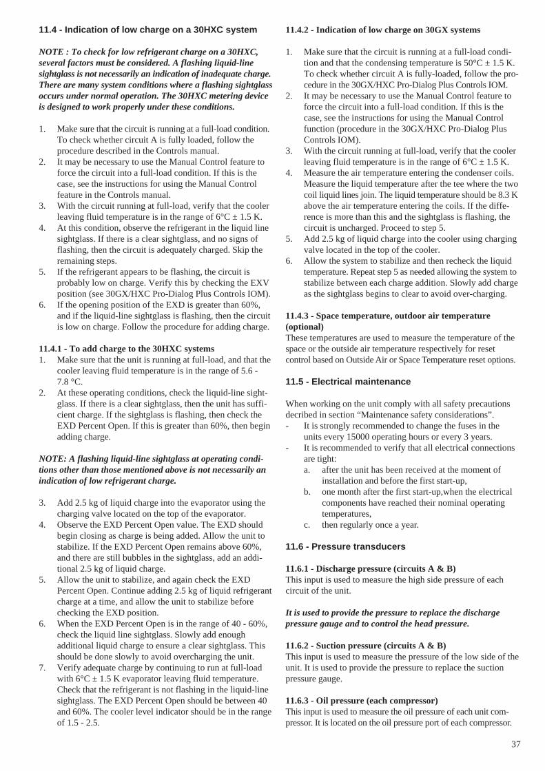
37
11.4 - Indication of low charge on a 30HXC system
NOTE : To check for low refrigerant charge on a 30HXC,several factors must be considered. A flashing liquid-linesightglass is not necessarily an indication of inadequate charge.There are many system conditions where a flashing sightglassoccurs under normal operation. The 30HXC metering deviceis designed to work properly under these conditions.
1. Make sure that the circuit is running at a full-load condition.To check whether circuit A is fully loaded, follow theprocedure described in the Controls manual.
2. It may be necessary to use the Manual Control feature toforce the circuit into a full-load condition. If this is thecase, see the instructions for using the Manual Controlfeature in the Controls manual.
3. With the circuit running at full-load, verify that the coolerleaving fluid temperature is in the range of 6°C ± 1.5 K.
4. At this condition, observe the refrigerant in the liquid linesightglass. If there is a clear sightglass, and no signs offlashing, then the circuit is adequately charged. Skip theremaining steps.
5. If the refrigerant appears to be flashing, the circuit isprobably low on charge. Verify this by checking the EXVposition (see 30GX/HXC Pro-Dialog Plus Controls IOM).
6. If the opening position of the EXD is greater than 60%,and if the liquid-line sightglass is flashing, then the circuitis low on charge. Follow the procedure for adding charge.
11.4.1 - To add charge to the 30HXC systems1. Make sure that the unit is running at full-load, and that the
cooler leaving fluid temperature is in the range of 5.6 -7.8 °C.
2. At these operating conditions, check the liquid-line sight-glass. If there is a clear sightglass, then the unit has suffi-cient charge. If the sightglass is flashing, then check theEXD Percent Open. If this is greater than 60%, then beginadding charge.
NOTE: A flashing liquid-line sightglass at operating condi-tions other than those mentioned above is not necessarily anindication of low refrigerant charge.
3. Add 2.5 kg of liquid charge into the evaporator using thecharging valve located on the top of the evaporator.
4. Observe the EXD Percent Open value. The EXD shouldbegin closing as charge is being added. Allow the unit tostabilize. If the EXD Percent Open remains above 60%,and there are still bubbles in the sightglass, add an addi-tional 2.5 kg of liquid charge.
5. Allow the unit to stabilize, and again check the EXDPercent Open. Continue adding 2.5 kg of liquid refrigerantcharge at a time, and allow the unit to stabilize beforechecking the EXD position.
6. When the EXD Percent Open is in the range of 40 - 60%,check the liquid line sightglass. Slowly add enoughadditional liquid charge to ensure a clear sightglass. Thisshould be done slowly to avoid overcharging the unit.
7. Verify adequate charge by continuing to run at full-loadwith 6°C ± 1.5 K evaporator leaving fluid temperature.Check that the refrigerant is not flashing in the liquid-linesightglass. The EXD Percent Open should be between 40and 60%. The cooler level indicator should be in the rangeof 1.5 - 2.5.
11.4.2 - Indication of low charge on 30GX systems
1. Make sure that the circuit is running at a full-load condi-tion and that the condensing temperature is 50°C ± 1.5 K.To check whether circuit A is fully-loaded, follow the pro-cedure in the 30GX/HXC Pro-Dialog Plus Controls IOM.
2. It may be necessary to use the Manual Control feature toforce the circuit into a full-load condition. If this is thecase, see the instructions for using the Manual Controlfunction (procedure in the 30GX/HXC Pro-Dialog PlusControls IOM).
3. With the circuit running at full-load, verify that the coolerleaving fluid temperature is in the range of 6°C ± 1.5 K.
4. Measure the air temperature entering the condenser coils.Measure the liquid temperature after the tee where the twocoil liquid lines join. The liquid temperature should be 8.3 Kabove the air temperature entering the coils. If the diffe-rence is more than this and the sightglass is flashing, thecircuit is uncharged. Proceed to step 5.
5. Add 2.5 kg of liquid charge into the cooler using chargingvalve located in the top of the cooler.
6. Allow the system to stabilize and then recheck the liquidtemperature. Repeat step 5 as needed allowing the system tostabilize between each charge addition. Slowly add chargeas the sightglass begins to clear to avoid over-charging.
11.4.3 - Space temperature, outdoor air temperature(optional)These temperatures are used to measure the temperature of thespace or the outside air temperature respectively for resetcontrol based on Outside Air or Space Temperature reset options.
11.5 - Electrical maintenance
When working on the unit comply with all safety precautionsdecribed in section “Maintenance safety considerations”.- It is strongly recommended to change the fuses in the
units every 15000 operating hours or every 3 years.- It is recommended to verify that all electrical connections
are tight:a. after the unit has been received at the moment of
installation and before the first start-up,b. one month after the first start-up,when the electrical
components have reached their nominal operatingtemperatures,
c. then regularly once a year.
11.6 - Pressure transducers
11.6.1 - Discharge pressure (circuits A & B)This input is used to measure the high side pressure of eachcircuit of the unit.
It is used to provide the pressure to replace the dischargepressure gauge and to control the head pressure.
11.6.2 - Suction pressure (circuits A & B)This input is used to measure the pressure of the low side of theunit. It is used to provide the pressure to replace the suctionpressure gauge.
11.6.3 - Oil pressure (each compressor)This input is used to measure the oil pressure of each unit com-pressor. It is located on the oil pressure port of each compressor.

38
11.6.4 - Economizer pressure (circuits A & B)This input is used to monitor the oil pressure differentialsupplied to the compressor.
11.7 - Oil charging - low oil recharging
11.7.1 - Addition of oil charge to 30HXC/GX systems
1. If the 30HXC/GX unit shuts-off repeatedly on Low oilLevel, this may be an indication of inadequate oil charge.It could also mean simply that oil is in the process ofbeing reclaimed from the low-side of the system.
2. Begin by running the unit at full-load for an hour and ahalf.
3. After running for 1-1/2 hours allow the unit to re-start andrun normally. If the Low Oil Level alarms persist, the unithas a low oil charge. Add oil to the oil separator, using theoil charging valve at the bottom of the condenser (30HXC)or at the bottom of the oil separator (30GX).
CAUTION: Do NOT add oil at any other location asimproper unit operation may result.
4. Make sure that the unit is not running when adding oil, asthis will make the oil charging process easier. Because thesystem is under pressure even when the unit is not running,it will be necessary to use a suitable pump (hand or electricpump) to add oil to the system.
5. Using a suitable pump, add 2 litres of Polyolester oil tothe system (CARRIER SPEC: PP47-32). Make sure thatthe oil level safety switch is NOT jumpered, and allow theunit to re-start and run normally.
6. If low oil level problems persist, add another 1 or 2 litresof oil. If it is necessary to add more than 4 litres of oil tothe system, then contact your Carrier distributor servicedepartment.
CAUTION: When transferring the refrigerant charge to astorage unit, oil may be carried along when the unit is notoperating. Reuse first of all the amount of refrigerant trans-ferred. After draining the oil, only recharge the amount drained(an excess oil charge may impair correct unit operation).
If an oil draining or recovery operation becomes necessary,the fluid transfer must be made using mobile containers.
11.8 - Integral oil filter change
An integral oil filter in the 06N screw compressor is specified toprovide a high level of filtration (3 µ) required for long bearinglife. As system cleanliness is critical to reliable system operation,there is also a prefilter (7 µ) in the oil line at the oil separatoroutlet.The replacement integral oil filter element part number is:
Carrier part number (including filter and O-ring): 06NA660016S.
11.9 - Filter change-out schedule
The filter should be checked after the first 1000 hours ofoperation, and every subsequent 4000 hours. The filter shouldbe replaced at any time when the pressure differential acrossthe filter exceeds 2.1 bar.
The pressure drop across the filter can be determined by mea-suring the pressure at the filter service port and the oil pressureport. The difference in these two pressures will be the pressuredrop across the filter, check valve, and solenoid valve. Thepressure drop across the check valve and solenoid valve isapproximately 0.4 bar, which should be subtracted from the twooil pressure measurements to give the oil filter pressure drop.The oil filter pressure drop should be checked after any occasionthat the compressor is shut down on a low oil pressure safety.
11.10 - Filter change-out procedure
The following steps outline the proper method of changing theintegral oil filter.1. Shutdown and lockout the compressor.2. Manually force the operation of the oil solenoid valve, in
order to press the internal valve shutter onto its seat.3. Close the oil filter service valve. Bleed pressure from the
filter cavity through the filter service port.4. Remove the oil filter plug. Remove the old oil filter.5. Prior to installing the new oil filter, “grease” the o-ring
with oil. Install the filter and replace the plug.
Before closing up the lube oil system, take the opportunityto replace the prefilter, as well.
6. When complete, evacuate the filter cavity through thefilter service port. Open the filter service valve. Removeany compressor lockout devices, the compressor is readyto return to operation.
11.11 - Compressor replacement
11.11.1 - Compressor rotation controlCorrect compressor rotation is one of the most critical applica-tion considerations. Reverse rotation, even for a very shortduration, damages the compressor.
The reverse rotation protection scheme must be capable ofdetermining the direction of rotation and stopping the compressorwithin 300 milliseconds. Reverse rotation is most likely to occurwhenever the wiring to the compressor terminals is disturbed.
To minimize the opportunity for reverse rotation, the followingprocedure must be applied. Rewire the power cables to thecompressor terminal pin as originally wired.
For replacement of the compressor, a low pressure switch isincluded with the compressor. This low pressure switch shouldbe temporarily installed as a hard safety on the high pressurepart of the compressor. The purpose of this switch is to protectthe compressor against any wiring errors at the compressorterminal pin. The electrical contact of the switch would bewired in series with the high pressure switch. The switch willremain in place until the compressor has been started anddirection of rotation has been verified; at this point, the switchwill be removed.

39
The switch that has been selected for detecting reverse rotationis Carrier part number HK01CB001. It is available as part of the"Compressor installation package" (part No. 06NA 660 013).This switch opens the contacts when the pressure falls below50 mm of vacuum. The switch is a manual reset type that canbe reset after the pressure has once again risen above 70 kPa. Itis critical that the switch be a manual reset type to preclude thecompressor from short cycling in the reverse direction.
11.11.2 - EXD troubleshooting procedureFollow steps below to diagnose and correct EXD problems.
Check EXD motor operation first (see procedure in the 30GX/HXC Pro-Dialog Plus Controls IOM). You should be able tofeel the actuator moving by placing your hand on the EXD.You should feel a hard knocking come from the actuator whenit reaches the top of its stroke (can be heard if surroundings arerelatively quiet). The actuator should knock when it reachesthe bottom of its stroke. If it is believed that the valve is notworking properly, contact your Carrier service department forfurther checks on:• output signals on EXD module• wire connections (continuity and tight connection at all
pin terminals)• resistance of the EXD motor windings.
11.12 - Corrosion control
All metallic parts of the unit (chassis, casing panels, controlboxes, heat exchangers etc.) are protected against corrosion bya coating of powder or liquid paint. To prevent the risk ofblistering corrosion that can appear when moisture penetratesunder the protective coatings, it is necessary to carry outperiodic checks of the coating (paint) condition.
11.13 - Condenser coil
We recommend, that finned coils are inspected regularly tocheck the degree of fouling. This depends on the environmentwhere the unit is installed, and will be worse in urban andindustrial installations and near trees that shed their leaves.
For coil cleaning proceed as follows:• Remove fibres and dust collected on the condenser face
with a soft brush (or vacuum cleaner).• Clean the coil with the appropriate cleaning agents.
We recommend TOTALINE products for coil cleaning:Part No. P902 DT 05EE: traditional cleaning methodPart No. P902 CL 05EE: cleaning and degreasing.
These products have a neutral pH value, do not contain phos-phates, are not harmful to the human body, and can be disposedof through the public drainage system.
Depending on the degree of fouling both products can be useddiluted or undiluted.
For normal maintenance routines we recommend using 1 kg ofthe concentrated product, diluted to 10%, to treat a coil surfaceof 2 m2. This process can either be carried out using a high-pressure spray gun in the low-pressure position. With pressu-rised cleaning methods care should be taken not to damage thecoil fins. The spraying of the coil must be done:- in the direction of the fins- in the opposite direction of the air flow direction- with a large diffuser (25-30°)- at a minimum distance of 300 mm from the coil.
The two cleaning products can be used for any of the followingcoil finishes: Cu/Cu, Cu/Al, Cu/Al with Italcoat or Polualprotection.
It is not necessary to rinse the coil, as the products used are pHneutral. To ensure that the coil is perfectly clean, we recom-mend rinsing with a low water flow rate. The pH value of thewater used should be between 7 and 8.
WARNINGNever use pressurized water without a large diffuser.Concentrated and/or rotating water jets are strictly forbidden.
Correct and frequent cleaning (approximately every threemonths) will prevent 2/3 of the corrosion problems.
Protect the control box during cleaning operations.
Never use a fluid with a temperature above 45°C to clean theair heat exchangers.

40
12 - START-UP CKECKLIST FOR 30HXC/GX LIQUID CHILLERS (USE FOR JOB FILE)
Preliminary information
Job name: ................................................................................................................................................................................................Location: .................................................................................................................................................................................................Installing contractor: ...............................................................................................................................................................................Distributor: .............................................................................................................................................................................................Start-up preformed by: ...........................................................................................................................................................................
CompressorsModel: ............................................................................................. S/N ..............................................................................................
CompresseursCircuit A Circuit B1. Model # ...................................................................................... 1. Model # .................................................................................
S/N ............................................................................................. S/N ..............................................................................................Mtr # ........................................................................................... Mtr # ...........................................................................................
2. Model # ...................................................................................... 2. Model # .................................................................................S/N ............................................................................................. S/N ..............................................................................................Mtr # ........................................................................................... Mtr # ...........................................................................................
CoolerModel # ........................................................................................... Manufactured by .........................................................................S/N .................................................................................................. Date .............................................................................................
Condenser (30HXC)Model # ........................................................................................... Manufactured by .........................................................................S/N .................................................................................................. Date .............................................................................................
Air handling equipmentManufacturer ..........................................................................................................................................................................................Model # ........................................................................................... S/N ..............................................................................................
Additional air handling units and accessories ........................................................................................................................................................................................................................................................................................................................................................
Preliminary equipment check
Is there any shipping damage? ....................................................... If so, where? ................................................................................................................................................................................................................................................................................................Will this damage prevent unit start-up? ..................................................................................................................................................
Unit is level in its installation Power supply agrees with the unit nameplate Electrical circuit wiring has been sized and installed properly Unit ground wire has been connected Electrical circuit protection has been sized and installed properly All terminals are tight All cables and thermistors have been inspected for crossed wires All plug assemblies are tight
Check air handling systems All air handlers are operating All chilled water valves are open All fluid piping is connected properly All air has been vented from the system Chilled water pump (CWP) is operating with the correct rotation. CWP amperage: Rated: ............ Actual............

41
Check condenser system (30HXC) All condenser water valves are open All condenser piping is connected properly All air has been vented from the system Condenser water pump (CWP) is operating with the correct rotation.Condenser water pump amperage: Rated:…….. Actual………
Unit start-up CWP starter has been properly interlocked with the chiller Oil heaters have been energized for at least 24 hours (30GX) Oil level is correct All discharge and liquid valves are open All suction valves are open, if equipped All oil line valves and economizer discharge bubbler valves (30HXC only if equipped) are open Unit has been leak checked (including fittings)
Locate, repair, and report any refrigerant leaks................................................................................................................................................................................................................................................................................................................................................................................................................................................................................................................................................................................................................................................
Check voltage imbalance: AB .................. AC ................. BC.................Average voltage = ..................................... (see installation instructions)Maximum deviation = .............................. (see installation instructions)Voltage imbalance = ................................. (see installation instructions) .
Voltage imbalance is less than 2%
WARNING: Do not start chiller if voltage imbalance is greater than 2%. Contact local power company for assistance.
All incoming power voltage is within rated voltage range
Check cooler water loopWater loop volume = ................................ (liters)Calculated volume = ................................. (liters)3.25 liters/nominal kW capacity for air conditioning6.5 liters/nominal kW capacity for process cooling
Proper loop volume established Proper loop corrosion inhibitor included .............. liters of ........................... Proper loop freeze protection included (if required) ........................ liters of ............................. Piping includes electric heater tape, if exposed to the outside Inlet piping to cooler includes a 20 mesh strainer with a mesh size of 1.2 mm
Check pressure drop across the coolerEntering cooler = ...................................... (kPa)Leaving cooler = ....................................... (kPa)(Leaving - entering) = ............................... (kPa)
WARNING: Plot cooler pressure drop on performance data chart (in product data literature) to determine total liters persecond (l/s) and find unit's minimum flow rate.
Total l/s = ..................................................l/s / nominal kW = ....................................
Total l/s is greater than unit's minimum flow rate Total l/s meets job specified requirement of .......................................... (l/s)
Check condenser water loop Proper loop corrosion inhibitor included .............. liters of ........................... Inlet piping to condenser includes a 20 mesh strainer with a mesh size of 1.2 mm

42
Check pressure drop across the condenser (30HXC only)Entering condenser = ................................ (kPa)Leaving condenser =................................. (kPa)(Leaving - entering) = ............................... (kPa)
WARNING: Plot condenser pressure drop on performance data chart (in product data literature) to determine total liters persecond (l/s) and find unit's minimum flow rate.
Total l/s = ..................................................l/s / nominal kW = ....................................
Total l/s is greater than unit's minimum flow rate Total l/s meets job specified requirement of .......................................... (l/s)
Perform TEST function (indicate positive result):
WARNING: Once power is supplied to the unit, check the display for any alarms, such as phase reversal. Follow the TESTfunction instructions in the Controls and Troubleshooting literature (follow the procedure in the Controls IOM).
External reset sensor ...................................................................Cooler pump interlock ................................................................
Cooler fluid select ........................................................................... Cooler pump control ...................................................................Minimum load select ...................................................................... Condenser pump control* ...........................................................Loading sequence select ................................................................. Condenser flow switch* .............................................................Lead/lag sequence select ................................................................ Condenser water sensors* ...........................................................Head pressure control .....................................................................Motormaster select* ....................................................................... *If installedWater valve type* ...........................................................................
To start the chiller
WARNING: Be sure that all service valves are open, and all pumps are on before attempting to start this machine. Once allchecks have been made, move the switch to "LOCAL" or "REMOTE" from "OFF".
Unit starts and operates properly
Temperatures and pressures
WARNING: Once the machine has been operating for a while and the temperatures and pressures have stabilized, record thefollowing:
Cooler EWT.................................................................................... Ambient temperature (GX) .........................................................Cooler LWT .................................................................................... Condenser EWT ..........................................................................
Condenser LWT ..........................................................................
Circuit A oil pressure ...................................................................... Circuit B oil pressure ..................................................................Circuit A suction pressure ............................................................... Circuit B suction pressure ...........................................................Circuit A discharge temperature ..................................................... Circuit B suction temperature .....................................................Circuit A suction temperature ......................................................... Circuit B discharge pressure .......................................................Circuit A discharge pressure ........................................................... Circuit B discharge temperature .................................................Circuit A liquid line temperature .................................................... Circuit B liquid line temperature ................................................

Order No: 13050-76 (phase 3), 02.2006 - Supersedes order No: 13050-76, 07.2003 Manufacturer: Carrier SCS, Montluel, France.Manufacturer reserves the right to change any product specifications without notice. Printed in the Netherlands on chlorine-free paper.