30C-9-20181022124532 · Title: 30C-9-20181022124532 Created Date: 10/22/2018 12:45:32 PM

May, 1936 - No. 209
30c in U.S.A. and Canada 1, 8 in the United Kingdom
2- in Australasia
THIS MONTH:
New High Efficiency Linear Amplifier
A High Power, Multiband Exciter
Inexpensive, Home -Made Rheostats
Quick Change 3 Band Transmitter
Multivibrator Adjustment
Simple Autotransformer Construction
A Low Cost, Kilowatt Transmitter
A Receiver with Performance Plus
www.americanradiohistory.com

***World's Fastest Sales Growth BECAUSE: World's Most Beautiful Refrigerator
PLUS THIS MUCH MORE
{ IN A SHELVADOR !!
~ï?
_ytsj. r'CF" c
a
, ir^
----------.
18 MODELS, 6 SIZES. PRICED FROM
$99.50 to $214.95, INCLUDING DE-
LIVERY, INSTALLATION AND FIVE - YEAR PROTECTION PLAN
Good Housekeeping
t Institute
.nn 4wt+' All prices slightly higher in. Florida, Texas, Rocky Mountain states and West
THE CROSLEY RADIO CORPORATION, CINCINNATI - POWEL CROSLEY, Jr., President
www.americanradiohistory.com
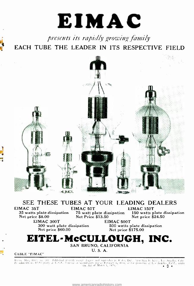
EIMAC presents its rapidly ' rowin,- family
EACH TUBE THE LEADER IN ITS RESPECTIVE FIELD
SEE THESE TUBES AT YOUR LEADING DEALERS EIMAC 35T
35 watts plate dissipation Net price $8.00
EIMAC 300T 300 watt plate dissipation Net price $60.00
EIMAC 50T 75 watt plate dissipation Net Price $13.50
EIMAC 150T 150 watts plate dissipation Net price $24.50
EIMAC 500T 500 watts plate dissipation Net price $175.00
EITEL- McCULLOUGH, INC, SAN BRUNO, CALIFORNIA
U. S. A. CABLE "EIMAC"
R \1,1 Irtst, u... .'a,. Published muntbl'. rseelt : Augua and "ir¡,teinl,ei lis Radio. Ltd.. Iicccrly Blvd., Los Angeles, (alit. By subscription, $2.5e scant in C.S.A. I ntered as second-class mirer February t,, leih, an the posru, rice at Lus Angeles Calif., under
the Act of March 3, I8-9, 3
www.americanradiohistory.com
Many new charts, tables, formulae, dia- grams. H u n- dreds of illus- trations.
kl
MAIL. COUPON BELOW
Greatest of All Radio Books
The 1936 edition of "THE RADIO HANDBOOK" eclipses
all others in its amazing content. Tells how to build any
kind of a receiver, from a one -tuber to a de luxe crystal -
filter superhet. How to build ANY kind of a c.w. or phone
transmitter from a one -tuber to a full kilowatt. Revolution-
ary data on new antenna systems for all -band operation.
New grid -bias controlled carrier phones. Complete 10-
meter chapter. All the new 21/2 and 5 -meter information.
Truly the book of books.
ALMOST 400 PAGES
ONLY ONE DOLLAR PER COPY
RADIO Magazine, 7460 Beverly Blvd., Los Angeles, Calif.
Please send me postpaid a copy of the 1936 "RADIO HANDBOOK ". I have enclosed $1.00 and am expecting a lot for my money.
Name Call
Street and Number
City and State
www.americanradiohistory.com
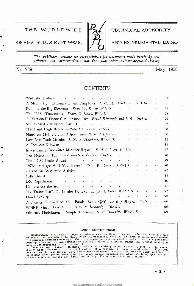
THE WOI,LDWIDE
OF AMATEUR,. SHORT WAVE.
TECHNICAL AUTHORITY
AND EXPEILIMENTAL RADIO
The publishers assume no responsibility for statements made herein by con- tributors and correspondents, nor does publication indicate approval thereof.
No. 209 May, 1936
CONTENTS
With the Editors - - -
A New, High Efficiency Linear Amplifier J. N. A. Hawkins, It "6AAR
Building the Big Rheostats- Robert S. Kruse, ll'1FG -
The "333" Transmitter -Frank C. Jones, W6AJF A "Sectional" Phone -C.W. Transmitter -Frank Edmonds and I. A. Mitchell
Self Excited Oscillators, Part II - - - -
"Hell and High Water " -Robert S. Kruse, 1171FG
Notes on Multivibrator Adjustment -Bernard Ephraim
Low Loss Tank Circuits -J. N. A. Hawkins, 1V6AAR
A Compact Kilowatt - - - - - -
Investigating Committee Minority Report -E. A. Roberts, W 78HC
Ten Meters in Ten Minutes -Herb Becker. lt76QD
The F.C.C. Looks Ahead - - - - -
"What Voltage Will You Have?"-Chas. W. Corer. It"RKVI
28 and 56 Megacycle Activity
Calls Heard - -
DX Department
Hams across the Sea - -
The Traffic Ten ", Dx Inhaler DeLuxe -Lloyd Al. Jones. 11e6DOB
Flood Activity - - - - - - -
A Quarter Kilowatt on Four Bands, Rapid QSY--Le Roy Moffett. 1r 91I
W6BGC Goes "Lazy X "- Maurice E. Kennedy, W6BGC - -
Efficiency Modulation in Simple Terms -J. N. A. Hawkins, W6AAR -
7
8
15
18
22
25
28
30
32
35
37
38 39
40
42
44
46
51
52
59
60
66
68
"RADIO " CONTRIBUTIONS
Contributions to our editorial pages are always welcome; though they will be handled with due care we assume no responsibility for those which are unsolicited; none will be returned unless - accompanied by a stamped, addressed envelope. We do not suggest subjects on which to write; cover those you know best; upon request, we will comment on detailed outlines of proposed articles, but without committing ourselves to accept the finished manuscript.
Since we regard current "chiseling"' policies as decidedly unfair, a small payment will be made, usually upon publication, for accepted material of a technical or constructional nature. Freehand, pencilled sketches will suffice. Good photographs add greatly to any article; they can easily be taken b, the layman under proper instructions. For further details regarding the taking of photographs and the submission of contributions see "Radio" for January, 1936, or send stamp for a reprint.
5 www.americanradiohistory.com

Phone: WHitney 9615 Published by Radio, Ltd.
Eastern Business Office: 500 Fifth Avenue. New York
Phone: CHickering 4 -6218
RADIO 7460 BEVERLY BOULEVARL)
LOS ANGELES
Direct all correspondence to the home office at Los Angeles except as otherwise requested.
Chicago Advertising Office: New York Circulation Office: 3618 No. Bernard St. 253 West 128th St.
Tel. JUNiper 5575 Tel. MOnument 2 -2812
Rates and Notices Single Copy Rates
On newsstands: 30c in U.S.A. and Canada 1/8 in the United Kingdom 2/- in Australia and New Zealand
By mail, postpaid from home office:
30c whicCanada, all countries
ch take the $2 60 subscription rate; back copies, 5c extra.
40c elsewhere; no extra charge for back copies when available.
(These rates do not apply to annual or other special issues)
Subscription Rates U.S.A.' (and possessions), Canada, An-
dorra, Argentina, Bolivia, Brazil, Chile, Columbia, Costa Rica, Cuba, Dominican Republic, Ecuador, Guate- mala, Haiti, Honduras, Mexico, New-
foundland, Nicaragua, Panama, Para- guay, Peru, Salvador, Spain (and 1Year 2Years possessions), Uruguay, and enzuela:
$2 50' 64.00 duties, if any, not
Elsewh1n, not California, add 3 % sale' itax.
3'25 530
FREQUENCY
Published monthly under date as of the following
month; ten issues yearly including special annual
number; the August and September issues (which
would normally appear in July and August) are omit-
ted. Short -term subscriptions are accepted pro -rata,
but no special numbers will be included.
Terms and Remittances Ternis, strictly cash or equivalent with order. All
foreign and territorial remittances must be payable at par in U.S.A. or Canadian funds or at current ex-
change in British funds. Cash, stamps, "bearer in-
struments", etc., are at sender's risk. Gummed, un-
used U. 5. postage stamps accepted in small amounts;
3c denomination preferred. Back Copies
Subscriptions cannot be started with back issues.
Back copies, if available, will be ebovpplied
from the
home office at single copy
Changes of Address Notice of change of address must reach us by the first
of month preceding nominal date of issue with Bach it is to become effective. We will not supply
issues nor pay forwarding postage because of failure
to receive such advance notice.
Advertising Advertising is accepted only at terms stated on our
current Advertising Rate Card which will be sent on
request to the Los Angeles or New York offices. For
classified advertising, see classified section of any
issue.
PRINCIPAL FOREIGN AGENTS Canada: T. A. Holmes, 815 W. Hastings St., Vancouver. Europe: N. E. Read, 37, Willow Street, Oswestry,
Shropshire, England. Australasia: "The Bulletin," Box 2521BB, Sydney.
McGills, 183 Elizabeth St., Melbourne. Swain & Co., Ltd., Pitts St., Sydney. Te Aro, 94 Courtenay Place, Wellington.
South America: F. Stark, Caixa 2786, Sao Paulo. " Revista Telegrafica ", Peru 165,13eunos Aires
Cable address: Radiopubs, Los Angeles
Eastern Editorial Office and Laboratory: Box 115,
Guilford, Connecticut
The Staff Technical and Editorial Department
Editor W. W. SMITH, W6BCX
Associate Editor K. V. R. LANSINGH, W6QX
Engineering Editors RoBear S. KRUSE,t WI FG J. N. A. HAWKINS, W6AAR
Assistant Editors HERBERT BECKER, W6QD GEORGE D. WALKER,2 W4CTO E. H. CONKLIN,4 W9FM CHARLES A. HILL, W6BRO RUFUS P. TURNER,3 W1AY
Technical Consultants RALPH O. GORDON, W6CLH JAMES M. SHARP, JR., W6DMY CHARLES D. PERRINE, JR., W6CUH
Laboratorian FAUST GONSETT, W6VR
Laboratory Assistants RAYMOND DAWLEY, W6DHG MARTIN A. BROWN, W6ABF JACK HARWOOD, W6DJZ Louts E. TOTH, WtBNR
Technical Draftsmen M. S. DAVIS WILLIAM ROBERTS. W3B01
Editorial Secretary D. O. WORTHINGTON
Business Department Publisher
K. V. R. LANSINGH Managing Editor
M. Q. HAURET Circulation Manager
B. L. HOVER Eastern Manager
V. R. LANSINGH
Correspondence and Manuscripts Address all correspondence and manuscripts to the
home office at Los Angeles except as follows: 1. Technical and constructional manuscripts and
relevant correspondence from east of the Missis- sippi River which may be sent to R. S. Kruse'.
2. Radioddities, Strays, and the like may be sent to Rufus P. Turners.
3. Calls Heard may be sent to George Walkers; also dx news and station descriptions from east- ern America and from transatlantic countries.
Unusable, unsolicited manuscripts will be destroyed unless accompanied by a stamped, addressed envelope.
Copyright, 1936. All rights reserved. Reproduction without permission is forbidden ; permission
is usually granted amateur radio papers on request. Printed in U.S.A. by
GLENDALE PRINTERS, GLENDALE, CALIFORNIA
iRAnto Laboratory, Box 115, Guilford, Connecticut. -'Box 355, Winston- Salem, North Carolina. 3159 W. Springfield Street, Boston, Massachusetts. 4512 N. Main Sr., Wheaton, Illinois.
e6 www.americanradiohistory.com

with the ED TORS
Diathermy Furor Not at all unexpected was the storm of pro-
test received from several manufacturers of radio -therapy equipment as a result of the di- athermy article in April RADIO. The objections were many and varied, but it was obviously a plain case of "pain in the pocketbook ".
Two manufacturers objected that the tubes specified would not give sufficient power for the needs of the physician. One of these manufac- turers until recently was foisting off on the un- suspecting medical profession a machine utiliz- ing a pair of carbon plate 210's! A third man- ufacturer claimed that the machine described was dangerous, inasmuch as 1400 volts gave much more power than needed, and intimated that if we knew the first thing about diathermy machines we would have designed it to work at 1000 volts instead of 1400 volts.
All of the objectors were unanimous in the opinion that we do not know the first thing about construction of diathermy machines and should "stick to our knitting ". But their as- sumption falls down from two standpoints: First, a diathermy machine is simply a short wave transmitter and who should be better qual- ified on their design than the engineers of a technical radio magazine? Second, of all the commercially -built machines we have had the opportunity to examine, every one had more or less of a tendency to go out of oscillation under certain conditions of loading; nearly half of them used raw a.c. on the plates; and only two were capable of more power output than the machine described in RAnto. To get this great- er power, equipment of a size all out of pro- portion to the additional output was resorted to. Certainly the greater power is no engineer- ing achievement under those circumstances, and more than 200 watts output is very seldom re- quired anyhow except for special applications.
Our stand on the lack of justification for more than one meter was attacked bitterly, ex- cepting by those manufacturers using but one meter. We simply point out that conversation with two different doctors well- versed in the use of diathermy revealed that the proper way to gauge treatment is by the reaction of the patient and the temperature of the part of his body under treatment, not by noting the value of r.f. circulating current flowing through the
[Continued on Pao' l.6J
On the Road to Cairo In 1938 the Cairo Conference will be faced
with a problem such as has not been presented at any previous gathering of the International Frequency Grabbers. Heretofore a Conference has consisted of a series of meetings to deter- mine how much territory can be allocated to commercial interests; the Cairo Conference will be the first to face a new bulwark ... not the feeble "requests" of feeble amateurs for a wee slice of ether pie, but a formidable demand that the privileges of the amateur be given wider recognition. At no previous time in amateur radio history has such a determined effort been made to prepare for what is to come ... an International Conference. Thus competition in the radio amateur publishing field has brought about a condition from which great benefits will be derived. It has been said that competi- tion is the life of trade; likewise, in this instance competition among amateur publishers will be the direct means of bringing about one of the greatest and most effective weapons for the protection of amateur radio, aggre.uivenes.r!
No longer will it be possible for an amateur delegate to self -appoint his way to a conference. The next time, a man will be sent who has first been approved by the king -pins of amateur radio. No man would risk his reputation by asking to be sent to a conference without adequate qualification. Thus, when a new light in amateur radio shines at the Cairo Conference, a feeling of uneasiness will undoubtedly pre- vail among those who have long dreaded the "requests" which the amateur has made. For- tunately for amateur radio, the drive on Cairo which was instituted by RADIO and R/9 two years ago, and which has continued with un- abated fury ever since, has made itself felt in the far corners of the world.
RADIO has merely taken the stand of the in-
former and the reformer. In so doing, it has aroused the amateur to action. Obviously such a prolonged, consistent campaign would soon have a telling effect on those who formerly assumed self -styled leadership of the amateur ranks. It is safe to predict that these men will not "be among those present" at Cairo. Because their past record was so openly exposed to the entire world, there are few who would choose to see these self -same men again among
1C6neenued Ere Page Al
7
www.americanradiohistory.com

The toward
A Nev, Hísk-Etfícíency Linear Amplifier
first step the prin-
ciple of dynamic shift in a vacuum tube amplifier oc- curred with the invention of the class B audio amplifier by Gordon and Barton working independently. The idea behind class B audio amplification was to find a way to cut down the input and plate
By J. N. A. HAWKINS, W6AAR
A neu' wrinkle applied to linear amplifiers which greatly in- picture studios. creases the output from a given tube, effects a saving in power. Normally, a film and results in 60 percent unmodulated plate efficiency. All the sound track is re- advantages of a controlled carrier linear amplifier from a power standpoint, and yet the carrier remains constant. The system is corded by mod - based on what the author tentatively terms "dynamic shift". ulating a fixed
light source both up and around a mean value of light. In other words, the unmodulated sound track re- ceives one half the maximum peak value of light available. Then sounds alternately increase and decrease this average light value. It was found that the background noise could be greatly re- duced by reducing the unmodulated light on the track; so a resting bias was placed on the light gate to shut it nearly to zero. When an audio signal comes along through the recording amplifier, part of the signal is rectified and applied to the light gate so as to oppose the resting bias and open it up to its normal op- erating point of one half the peak value. Thus there is a dynamic shift in the axis about which the light values vary. This axis shift occurs in accordance with the syllabic modulation (0 to 20 cycles per second) in the signal to be re- corded, whether voice or music. R.C.A. devel- oped a similar dynamic shift device for their
Rr E XCITER MODULATED AMPLIFIER
MODULATOR
uNEAR RF AMrt6IER
BIAS SUPPLY
AUDIO CMANNEL
AUnO RECTIFIER
MV PLATE SUPPLY
VARIACTOR I
SATURABLE REACTOR -f
'FRIDAY' CIRCUIT/ AC POWER MAINS
Block Diagram of Expanding Linear Amplifier System
loss to a power amplifier when no signal is present on the grid. The plate efficiency of a class A amplifier is zero when no signal is pres- ent on the grid. Thus all the plate input must he dissipated from the plate as heat when the amplifier is resting, and low overall output ef- ficiency results. The class B audio amplifier makes the signal on the grid release the flow of plate current from the plate power supply so that the plate input and plate loss is low when the amplifier is resting. Strictly speaking, the class B audio amplifier is not a dynamic shift amplifier, as the bias axis is fixed. How- ever, the objective behind the dynamic shift class BC linear amplifier is exactly the same as that which mothered the invention of the class B audio amplifier. The idea is to reduce the unmodulated plate loss by increasing the unmodulated plate efficiency and by reduc- ing the plate power input. In the class B audio amplifier the input is reduced in the resting condition by reducing the d.c. plate current, keeping the plate voltage constant. In the dynamic shift linear amplifier the plate current is kept constant while the d.c. plate voltage is reduced when unmodulated.
The first real use of dynamic shift amplifi- cation came when the Bell Laboratories devel- oped the "ground noise reduction amplifier'. for use in sound -on -film recording in the motion
8
SCOOP The new Hawkins expanding class BC linear
amplifier effectively doubles the output obtain- able from a conventional class B amplifier, and probably will result in a radical change in the design of phone transmitters. 200 watts of car- rier may he obtained from a pair of 211's without the necessity for well -regulated power supplies or more than 1.5 watts of audio power. In this new system the average carrier ampli- tude is constant and is entirely independent of the modulation. We believe broadcast stations will look with interest on this new develop- ment which will cut tube costs 50% in the final linear amplifier.
The figures given in the tables are quite conservative, and for amateur use may he ex- ceeded considerably with certain types of tubes, much as is being clone with controlled carrier linear amplifiers. When resting, a controlled carrier linear amplifier operates at reduced in- put, but at reduced efficiency. The expanding linear amplifier works at reduced input when ;sting, but at increased efficiency, and the av- erage carrier does not vary as it does in the controlled carrier system. EDITOR.
www.americanradiohistory.com

o o 00
$a I 1
X
-4-ENVELOPE OF R.F.EXCITATION
NOTE: MODULATION CAPABILITY EXPANDED TO 100%
Figure 1
The Class B Expanding Linear Amplifier, 100% Modulated
type of film recording which "blacked out" the unused portion of the sound track.
The next application of the dynamic shift amplifier was the compandor developed by the Bell Laboratories for use on their transatlantic telephone circuits. Volume range of a com- munications channel describes the range in
sound amplitude that the system can handle. The minimum value is set by circuit noise, and the maximum value is set by the overload, or distortion point. The volume range of the hu- man voice is somewhat greater than the volume range of the transatlantic telephone circuits; so
the compandor is used to compress the volume range at the transmitter and to re- expand it
again at the receiver so that the distant listener hears approximately the same volume range as the sender puts into his telephone. Volume range compression and expansion both utilize dynamic shift amplification, although the two work in opposite directions. In the range ex-
pander (which also is used in the new R.C.A. electric phonograph) the gain of the audio channel is controlled by the incoming signal. When no signal is present the gain is low, due to high resting bias. When a signal is applied to the input of the expanding channel, part of it is bypassed to a rectifier which applies the
syllabic components to buck the bias voltage which controls the amplifier gain. The larger the signal the higher the gain. Thus a loud sound is amplified more than a weak sound and if two sounds applied to the amplifier input had a loudness ratio of five, they might come out of the channed with a loudness ratio of twenty or more. Thus note that volume range expansion works exactly opposite to the auto- matic gain control system used in most modern receivers. The autogain circuit in a receiver is really a special form of volume range compres- sor. It tries to bring all signals to the same level. Therefore, to a certain extent, autogain utilizes the principle of reverse dynamic shift.
Controlled carrier modulation utilizes dynam- ic shift amplification in exactly the same man- ner as the various systems used by the motion picture industry to reduce ground noise on sound tracks. However, the object is to reduce QRM and resting plate loss and not to reduce ground or background noise; but the dynamic shift process takes place in the same way. Some of the audio signal is rectified and used to con- trol the average carrier output of the modulated amplifier. This syllabic variation in average carrier output, in turn controls the input and output from a linear class B amplifier which
9
www.americanradiohistory.com

L 1.7 n
Experimental Linear Amplifier Being
follows the modulated stage. Controlled carrier modulation has one disadvantage in that var- iation in average carrier output usually distorts the received signal in a receiver using con- ventional automatic gain control. The dynamic shift linear amplifier is simply a controlled car- rier system without any syllabic variation of the carrier.
The bias shift class A audio amplifier (see RADIO for June, 1935, page 21) utilizes a rec- tifier circuit to increase the bias at low signal levels and thus cut down the resting plate loss. This amplifier is strictly class A as plate cur- rent flows throughout the cycle and the use of the push -pull circuit is unnecessary to reduce even- harmonic distortion, as the distortion is approximately the same as in any class A am- plifier. This is one of the simplest applications of the dynamic shift principle.
The class BC linear or bias modulated am- plifier, developed by the writer in 1933, also is a form of dynamic shift amplifier although it is not analyzed in the same manner. The shift in bias axis does not occur at a syllabic fre- quency rate but at an audio frequency rate, which greatly simplifies mathematical analysis.
The analysis of dynamic shift is still rather complex although it looks as if the conception and its analysis may become greatly simplified by a method which we hope to be able to pre- sent in the near future.
In any case the operation of the expanding class B linear amplifier may be visualized by imagining the presence of a good man "Friday'', who stands watching the volume level indicator on a phone transmitter and who "cranks up"
10
Tested in the "Radio" Laboratory
the bias and plate voltage on the linear r.f. amplifier as the volume level indicator swings up. Thus the linear amplifier is allowed to put out undistorted peaks of 100% modulation when required, but the input is way down when resting so that the tubes actually can dissipate less heat resting than they do when running wide open. The man "Friday" has to keep his wits about him because he has to increase the plate efficiency of the linear amplifier when un- modulated by reducing its modulation capabil- ity in order to keep the average carrier ampli- tude constant. However, this is not difficult to do if the "Friday" circuit is properly adjusted.
A block layout of a typical transmitter using an expanding linear amplifier is shown in di- agram A. Note that the rectified audio signal is used to control the plate and bias voltage to the linear amplifier. The voltage outputs of the plate and bias supplies must vary together in order to maintain the fixed bias at the cut -off value.
The plate and bias voltages are varied to- gether by means of a saturable reactor (Vari- actor) whose a.c. winding is in series with the 110 volt a.c. line which supplies power to the plate and bias transformers for the linear am- plifier. See figure 4. When direct current flows through the saturating winding on the primary reactor it reduces the a.c. voltage drop across the reactor. The more d.c. the lower the voltage drop. Thus the saturable reactor affords a con- venient means of dropping the line voltage to the primaries of the plate and bias transform- ers. The d.c. controlling current is obtained by rectifying some of the audio output of the mod-
www.americanradiohistory.com

8 o O á Ó ra- ó _ 0 aO) o I 1 I
8 p0 o0 C N fN
ÓO
a óó
úî
oO n M
I
p.
l
INSTANTANEOUS AXIS (SUM OF BIAS AND DEGENERATIVE FEEDBACK VOLTAGES),
I
(J ENVELOPE OF R.F. EXCITATION
NOTE: MODULATION CAPABILITY EXPANDED TO 100 .7.
Figure 2
The Class BC Expanding Linear Amplifier, 100% Modulated
ulator and applying it to the saturating wind- ing. This is quite similar to the Variactor sys- tem of effecting carrier control. For more data on the theory and construction of these satur- able control reactors see RADIO for March, 1935.
The Expanding Linear Amplifier Figure 1 shows a graph of a conventional
class B linear amplifier, completely modulated. The operating point on the dynamic character- istic (solid line) is P and as it is just half- way up the characteristic, the amplifier has 100% modulation capability and the average plate efficiency is three quarters of the max- imum instantaneous peak plate efficiency. As the maximum instantaneous peak plate efficien- cy of a class B amplifier has a theoretical limit at 79.17% and a practical limit at about 66% ,
the maximum attainable average plate efficiency under complete sine wave modulation is about three quarters of 66 %, or 50 %.
Ordinarily, when a conventional class B lin- ear amplifier is unmodulated the average plate efficiency drops to one half of the instantaneous peak value. Thus few class B linear amplifiers with 100% modulation capability have an av- erage unmodulated plate efficiency above 33 %. However, if the modulation capability is pur- posely limited to some value below 100% mod- ulation the unmodulated plate efficiency can be materially increased.
The unmodulated average plate efficiency is related to the modulation capability by the fol-
lowing formula (applicable only to class B op- eration)
6600 EffR
100 + MD
Where EffR is resting, or unmodulated plate efficiency and K. equals percentage modulation capability.
Thus if the modulation capability of a linear amplifier be purposely limited to 66 %, the av- erage unmodulated plate efficiency becomes 40% instead of the 33% unmodulated effi- ciency which was obtained with 100% mod- ulation capability. The expanding class B linear operates with 66% modulation capability (16.6% axis shift) unmodulated, but the mod- ulation capability is expanded up to 100% when the amplifier is modulated. Thus the use of dynamic axis shift allows the class B ex- panding linear amplifier to utilize the advan- tages of low modulation capability when resting, yet allows full sideband output when complete- ly modulated. This feature means a net increase of about 33% in the class B linear r.f. carrier output that can be obtained from any given tube. This limitation of modulation capability to 66% in the resting condition is effected by re- ducing the d.c. plate and bias voltages 16.6% under the maximum values used when the amplifier is operating completely modulated.
11
www.americanradiohistory.com

o O 00
ñr- a
1
BIAS SHIFT
ÓW 11:q
X PLATE -CURRENT /i"
_ S4. o % 0/ ?./. 01
¡y p .
W CSJN'
th Pp, `y
P/b W
rsi Ó c P UW I- p d1 It g °o co
h O , , o , 4 y _
o
Ú Ir
.6 ,I,P f O N
,/i O w O 1/ MI 1' / 4
1 N
b # + +
--
r
NOTE: MODULATION 11
CAPABILITY LIMITED }- TO 337. RESTING
BIAS AXIS AT COMPLETE MODULATION
OPERATING POINT c COMPLETELY MODULATED RESTING BIAS AXIS
Figure The Class BC Expanding Linear Amplifier,
This represents an axis shift of 16.6% and is the optimum value for class B operation. This amount of axis shift was determined by form- ulae to be given later. The point is that the d.c. plate power input to the final stage should us- ually decrease from the completely modulated condition to the resting condition by an amount of power equal to the maximum sideband pow- er output when completely modulated. If this is done the plate loss resting will be the same as the plate loss completely modulated. If less than 16.6% axis shift is used the plate loss resting will be greater than the plate loss when completely modulated and the power output will be limited by the unmodulated loss. There is no point in using more than 16.6% axis shift and reducing the resting plate loss below the loss completely modulated, as no in- crease in power output would result.
The following table shows typical maximum operating conditions for a single 211 used as a class B expanding linear amplifier, observing the maximum plate loss limitation of 100 watts dissipation.
Note that by using the expanding class B linear amplifier the maximum unmodulated car- rier output which can be obtained equals about two thirds of the rated plate dissipation of the tube used. As this output can be obtained now from the conventional class BC amplifier (non - expanding) , there is little advantage in the use
12
OPERATING POINT RESTING
3
Resting Condition (Axis Shift 33%)
of the class B expanding amplifier. It was considered necessary to discuss it, however, to show the tremendous advantage in the use of the expanding class BC amplifier.
EXPANDING CLASS B OPERATION (TYPE 211)
Completely modulated
Modulation capability 100% Plate efficiency (average) 50% Carrier output 66 Watts
Re.uing 16.6% ihift
66% 40%
66 W. S;deband output 33 W. 0 W. Plate loss 100 W. 100 W. D.c. plate input power 200 W. 166 W. D.c. plate current 150 Ma. 150 Ma. D.c. plate voltage 1333 V. 1111 V. D.c. bias voltage -110 V. -90 V.
The Expanding Class BC Amplifier A class BC amplifier differs from a class B
amplifier only in the use of an unbypassed cathode bias resistor across which a degenerative audio feedback voltage is developed which im- proves the linearity and plate efficiency of the class BC amplifier over the class B amplifier. (EDITOR'S NOTE: See a complete discussion of class BC operation on page 68 of this issue.)
The great advantage of expanding class BC operation and normal class B can best be seen by the following examples. Using a 211 type of tube it is found that about 50 watts of carrier output is all that can be obtained operating as a
normal class B linear amplifier. The use of ex- panding class B amplification allows about 66
www.americanradiohistory.com

watts of unmodulated carrier, while the use of expanding class BC amplification allows 100 watts of unmodulated carrier to be obtained from the 211 type of tube. The gains in output possible through the use of expanding class BC operation are even more marked with the 150T- 354 type of tube, where the momentary plate loss can be 150% of the normal tube loss rating without any damage.
The operation of the expanding class BC linear amplifier can best be seen by the two curves of operation, figures 2 and 3. In figure 2 the amplifier is shown operating fully mod- ulated. This curve is exactly the same as that for any conventional class BC linear amplier. The amplifier uses the dynamic grid voltage, plate current characteristic indicated by the solid line. The operating point is P1 and the average bias, when completely modulated, is 470 volts. (The d.c. plate voltage at this point was slight- ly over 2800 volts for this particular set -up.)
Note the point P on the characteristic in- dicated by the dashed line parallel to the solid line characteristic (figure 2). This is the op-
211 V
CN
RIAS 060 TI
SUPPLY I- d0\ T2 ¡ y 1 T3
PLATE SUPPLY
1-(1
AUDIO FROM MOD.
AXIS SHIFTER SRI
100000
I + L
6AS S
7,500
R I
8
.h350 ylíOV!AC -------I Figure 4
110 AC
r TO CARRIER COM
R NRESATOR WHEWIRED
fURIAC TOR
"fRID4Y CIRCUIT"
HY. PLATE SUPPLY TO
MODULATED CLASS C STAGE
COMPENSATING IVARIACTOR W
110V AC
20011
B+300
FROM CATHODE RESISTOR R
EXPANDING UNEAR, OR FROM LINEAR RF CARRIER RECTIFIER
Figure 5
Carrier Compensator (Required Only Under Certain Conditions).
erating point when the transmitter is unmod- ulated. The dashed characteristic is that of the resting or unmodulated condition, thus indicat- ing the dynamic characteristic shift between the resting and fully -modulated conditions.
Figure 3 shows a curve similar to that of figure 2 except that the transmitter is resting, or unmodulated (33% axis shift) , while figure 2 shows the 100% modulated condition. Note that the total bias is now only 391 volts, (plate voltage about 1900 volts, resting) . The operat- ing point on the resting dynamic characteristic is the point P. Note that the points P and P1
represent the same average value of plate cur- rent. Thus the average d.c. plate current (as measured on a meter) is the same resting or 100% modulated. As the plate load impedance (antenna coupling) is the same resting or com- pletely modulated, constant plate current means that the average carrier amplitude remains con- stant and independent of axis shift.
Note that the average r.f. excitation voltage is the same in the resting and the completely modulated conditions, but that the average d.c. grid current is greater in the resting condition. Thus the average load on the driver stage is
greatest when unmodulated, which is just the opposite of the conventional linear amplifier. It follows that less artificial stabilization of the driver load is necessary with the expanding linear amplifier than with conventional linear amplifiers.
The operating point P on figure 3 represents point of 60% average plate efficiency when un- modulated (assuming 80% as maximum class BC positive peak efficiency) . If the point P were just halfway up the dynamic characteristic (halfway between plate current cut -off and the diode bend, or quasi -saturation points), the modulation capability would be 100 %. How- ever as the point P is three quarters of the way
13
www.americanradiohistory.com

up the characteristic the maximum modulation capability in this resting condition is only 33 %. The modulation capability could have been maintained at 100% for the resting condition but then the average d.c. plate current would have dropped to two thirds its completely mod- ulated value and the same drop would occur in carrier amplitude. Thus the result would be simply controlled carrier. 33% modulation capability in the resting condition ensures that a steep -front audio signal will not catch the modulation capability napping and cause over - modulation (flattening of the positive audio peaks).
The resting plate voltage in the set -up de- scribed above is 33% under the maximum plate voltage applied during periods of 100% mod- ulation. In other words, the plate voltage in- creases 50% above the resting voltage when completely modulated. This represents an axis shift of 33 %.
As the maximum output from the expanding linear amplifier is usually limited by plate loss in the completely modulated condition, it is always necessary, when designing such an am- plifier, to start with the 100% modulated con- dition and then work backwards to determine the resting conditions. Thus we will define dynamic axis shift as a percentage drop in plate voltage and bias from the completely modulated condition, rather than a percentage rise above the resting condition.
It should be noted that the 33% dynamic axis shift discussed above is an arbitrary choice. The shift can be anything between zero shift and 50% shift. The shift can not exceed 50% and still keep the carrier constant. The follow- ing table (applicable only to class BC oper- ation) shows the effect of various percentages of axis shift downward from 100% modulation on the plate efficiency and modulation capability in the resting condition.
CLASS BC OPERATION
Percentage drop in plate and pack bias voltage (axis shift)
Resting plate ef- Resting fi. iency (taking modulation .,tt' /c as peak) capability
0 % 40 % 100% 20.83% * 50 % 60% 25 % 53.3% 50% 33 % *0 60 % 33% 50 % 80 % 0%
* The 20.835 axis shift is recommended for those tubes whose plate loss limit may not be exceeded even momentarily.
* * The 33% axis shift is recommended for those tubes whose plate loss limit may be exceeded momentarily under voice modulation by 50 %.
14
The relationships shown in the preceding table were obtained from the use of the following formulae from which the resting plate efficiency and resting modulation capability can be ob- tained for any degree of dynamic axis shift.
EffR - 100 Effp
100+Me
Me-100-2S
50 Effp EffR -
(100 - S)
Where EffR equals resting, or unmodulat- ed plate efficiency.
Effp equals maximum attainable instanta- neous peak plate efficiency.
Me equals percentage modulation cap- ability.
S equals percentage dynamic axis shift downward from 100% modulated to resting condition.
Note that these formulae can be applied to either expanding class B or expanding class BC operation by inserting a suitable value of Effp, which is taken as 80% for class BC operation and as 66% for class B operation. These values will be about right for operation of most tubes at or slightly above normal rated plate voltage. This means about 750 volts for a 210 or 801: about 1250 to 1500 volts for tubes of the 800 and 211 general types, and at least 1750 to 2000 volts on the higher -voltage low C tubes such as 150T, 354, HF300, etc. 852's will re- quire at least 2500 to 3500 volts to make them get up and really go due to their rather high average plate resistance at lower plate voltages.
With an axis shift of 33% downwards the plate loss is least in the resting condition and rises 50% under complete sine wave modula- tion. As the unmodulated plate efficiency is
60% with this much axis shift the maximum carrier power output will be one and a half times the resting plate loss on the tube used in the expanding linear amplifier. The tube has to be able to stand the additional plate loss which occurs during modulation without dam- age. All the tantalum plate tubes and some of the moly and carbon plate tubes will stand a momentary overload of 50% above rated plate loss. [Conttnued on Page -4]
www.americanradiohistory.com

Building the Big Rheostats By ROBERT S. KRUSE
It was certainly a mistake to show the big rheostats or "load racks" to over two thousand amateurs at a recent radio meeting. Altogether too many have written for further details, and for photographs! The photographs should of course have been in the January RADIO article, but unfortunately were damaged in transit.
ir/frt/ilt+tl/ d d '! tt l'l;t1 u is .,
The 1 kilowatt "number one" rheostat. 55 steps from 10 to 1000 ohms.
Bill of Materials for the "Number One" Rheostat
Baseboard 34" x 6" x 1/2 " (soft wood). Socket stash 34 " x 23/4" x 7/8" (dressed) soft wood.
2 cleats (better 3) 9" X 23/4" x 7/8 " (dressed) soft wood.
12 woodscrews 1" no. 7 flathead for assembling wooden frame.
15 feet of no. 16 bare wire. 20 woodscrews, 1/2" no. 6 nickled roundhead for
switches. 20 woodscrews I" no. 8 flathead steel or brass
for sockets. 10 porcelain base s.p.d.t. midget switches. 1 or 2 terminal strips with standoff spacers and
screws to match. 10 resistance units with Edison screw base.
10 lamp receptacles. Porcelain base not recom- mended. Ir possible use the new bakelite type with bakelite terminal cover retained by spring snap -ring (commonly available).
Bill of Materials for the "Number Two" Rheostat
1 baseboard 28" x 6" x 1/2" soft wood. 3 cleats 23/4" x 7/8 " x 6" soft wood.
10 tamp receptacles as for number one. 10 feet of no. 16 bare copper wire.
2 lengths of "spaghetti ". 2 binding posts or one -terminal strips. 5 porcelain base s.p.s.t. midget switches.
10 woodscrews. 1/2 " no. 6 roundhead nickled for switches.
20 woodscrews, 1" no. 8 flathead for sockets. 9 woodscrews, 1" no. 8 flathead for assembling
wood frame.
Therefore to escape writer's cramp and to keep down the bill for photos, we'll go over the story again briefly, with pictures.
The "Number 1" Rheostat The affair that looks a little like a row of
factory chimneys is actually an easily -made rheo- stat with 55 steps and large wattage- dissipation ability. The chimneys are Ward - Leonard Ed- ison -base resistors, available in a number of re- sistances and wattage ratings, and easily ex- changed in the bakelite receptacles which hold them, though intended for ordinary lamps. The particular type of receptacle used is especially convenient. Using 100 ohm units the rheostat ranges from 10 ohms to 1000 ohms in 55 steps, while the safe wattage dissipation slides down and up again as shown by figure 1, the variation being different from that of other sorts of rhe- ostats, though they all vary in some manner. (Consider the way the ordinary rotary rheostat burns up at one end.) If the units are 100 watters the lowest dissipation is 100 watts and the highest is 1000 watts, 10 units being used.
Child's Play As was said in the January article, the 55
switch positions can be learned in 5 minutes. Looking at the photo and at the diagrams ap-
* 11- 1
The "number two" rheostat. About 390 watts, 20 steps.
pearing as figure 2 we see that there are 10 switches, each with a single blade, but double throw. The resistors are all connected between switches as shown at figure 2A.
Now we start to throw switches. In figure 2B we put switch No. 10 in the "up" closed posi- tion and have all 10 resistors in series. Now we run through an ordinary 10- point- rheostat range, by closing the switches "up" one after the other
15
www.americanradiohistory.com

in the order 10, 9 (this is figure 2C) , 8, 7, 6 1, at the end of which we have one resistor across the line. We have come from 1000 ohms to 100 ohms.
At this point ordinary rheostats start to jump too fast, but this one has 45 more points left!
Leaving no. 1 closed "up" we pull all other switches and as in figure 2E close the no. 10 switch "down ", then proceed switch- after -switch until we reach the arrangement of figure 2F, which is 50 ohms at the 19th rheostat step. Un- like the usual rheostats, the current- carrying ability is now on the way up (which is what we need as the current is getting bigger, of course).
Once more the switches are "pulled" except no. 1 and no. 2. Now no. 10 is closed "up" and we are off once more. Eventually we ar- rive at figure 2G, with 10 ohms, able to dis- sipate a kilowatt. This is the 55th and last step.
That is about all except the list of material, which is at the beginning of this paper.
The "Number 2" Rheostat The other rheostat, with the lamps used as
resistors, corresponds to the diagram appearing as figure 3. It is more limited in its uses as it has only a parallel range (20 steps instead of
-s loo %
10 UNITS IN SERIES
TYPICAL"TRICK" POINTS ADDED BY \i
SWITC E TE XSYSTEM lA xx
A- LESS OHMS MORE --.- le
45 ADDITIONAL RHEOSTAT POINTS PROVIDED RANGE
SYS EM( "TRICK" POINTS POINTS NOT COUNTED)
Figure 1
What can be done with 10 resistors in the circuit of figure 2.
2 3 4 5 6 7 e 9 10 55). For most amateur uses it is convenient to use cheap lamps having wattage ratings as marked in figure 3. The switching scheme is as follows:
Switches closed Relative current (,ee figure 3) (approximate only)
A 1
B 2
A,B 3 B,C 4 A,B,C 5
A,D 6 B,D 7 A,B,D 8 B,C,D 9 E 10
Now keep E closed and re -run the first nine
o W0
e-9 10 BUS
O
o BUS
SW. 19 CLOSED UP' 1ST STEP 000 OHM
ALL IN SERIES S
2ND STEP
(ONMS)
OTH STEP (100 OHMS)
SW.* ID CLOSED 'DOWN' IITH STEP
SW 4V9 CLOSED,
- - - - - - -
CLOSE SWITCHES UP UNTIL
- - Q o _ a . THE ABOVE CONCLUDES THE 10 POINT RHEOSTAT RANGE. NOW
'PULL' ALL SWITCHES BUT *I AND PROCEED AS FOLLOWS IN THE PARALLEL RANGE . .
_LEAVE CLOSED 'UP"
arrangements, ending up with: A,B,C,D 20,..
The demerits of this rheostat are that the circuit is repeatedly "jumped" back and forth instead of proceeding steadily in one direction as does the number 1 rheostat. It is also much easier to get mixed up, as the sequence is not straightforward in this number two rheostat, even though 5 switches do seem to be simpler than 10.
There is nothing to keep one from using lamps in the number 1 rheostat, though one defect of lamps should be noticed: Their resist- The
in this
(90 OHMS)
one"
100 900 IN PARALLEL WITH THE IDO OHNS
CLOSE SWITCHES 9,8 7. 6, ETC. "DOWN" UNTIL
19TH STEP (SO OHMS)
2 UNITS NOW IN PARALLEL
NOW PULL SWITCHES 3.4.5.6.7 8.9,10 CLOSE NO.1O'UP'ANO AGAIN WORK TO LEFT UNTIL NO.3 IS CLOSED-UP"- 27TH
REMAINING PROCEDURE LEADING FINALLY TO
55TH STEP (10 OHMS)
ALL IN PARALLEL
Figure 2 switching scheme which is callsd "number
paper, and is shown in the first photograph.
16
www.americanradiohistory.com

i/ s-/ c/ o/ E/ RELATIVE CVRRENT1 E E S
RELATIVE OHMS 10 S S 2
(SEE TEXT WARNING)
10
OUT
Figure 3 The more limited or "number two" switching scheme. This is shown in the second photograph.
ance changes widely with the current, which is to say that the actual resistance is never known. With the resistance units there is no such un- certainty.
TO THE WIVES OF HAMS By ONE OF THEM
I don't know you personally, Mrs. W7XYR or you, Mrs. VE5KZ, or you either, Mrs. W4JPQ, but we all know to an amazing de- gree of accuracy just what happens when our husband turns from a man into a ham; even as did Dr. Jeckell into Mr. Hyde. True, he does not sprout teeth and new hair after quaf- fing a vile potion, but he does grow glassy of eye and forgetful of time when he beholds a super -tube or a split stator condenser. Then, dear madam, you have a species apart from the rest of mankind -a ham.
This odd creature isolates himself in a corner of your home and calls it "the shack ". He plas- ters the walls with innumerable gaudy cards from all corners of the globe (that is, if he's lucky). Around the "shack" run thousands of wires in mad profusion. Should you peer be- hind the cupboard, abundantly decorated with hundreds of little knobs (he affectionately dubs it a "transmitter ") you would see a mass of light globes with wiry intestines; there would be sockets with green thread around their waists and lots of little "condensers" bearing a marked resemblance to a fish scale that swing back and forth like a cradle -also on the front of the cupboard are speedometers that seem to have the jitters, and so would I if forced to such permanent close proximity with the re- ceiver. Of all the soul -tearing sobs of man- kind, none can quite equal the receiver in the act of receiving. From its black body will sud- denly rip a shrill piercing scream of pain (the neighbors accused him of beating me) . It will sob in great gasping breaths as though a long, jagged wire had torn loose and was stabbing it through the heart. Panting hoarsely it will sink into a low rasping cough, then finally give
up the spirit entirely, only to scream with an- guish anew in a moment or two.
Your ham will then perhaps rub his hands in fiendish delight and proceed to babble in a strange vernacular, calling himself by a formula, comprised of letters and numbers, and you are labeled the x.y.l. Incidentally, "x.y.l." means x young lady. How I ground my teeth in help- less rage the first time I heard that. He then, with invariable regularity, calls his fellow ham "old man" (even if 14 years old) and drones for hours on the subject of CQ. He complains of "fading" and of some one on top of him, then offers a wild conglomeration of technical excuses for the elements.
But, my pretty, this is naught; a mere trifle. Have you ever been motoring of a Sunday after- noon and have him "succumb "? No? Then let me reveal all. He will be drawn, even as a moth to a flame, to a tall, thin pole, perched precariously on someone's roof ; and then he'll start to produce symptoms. Before you know it, he slides from the car and barges to the front door (providing he has not spotted the "shack" elsewhere) and knocks. A stranger appears. They gaze intently into each other's eyes. Finally one will speak the magic sentence containing ham dialect. If the other returns in like argot, then you, my patient, are doomed. You watch the golden sun wallow in the west - you watch the playing children homing as even- tide approaches -you feel the cool fingers of the night breeze creep around ankles and neck. You sit on your left leg; you sit on your right leg; you concentrate on the front door; you concentrate on your husband. The gnawing pain of hunger is heightened by the aromas of Sunday repasts floating through the atmosphere; you wish you'd stayed home; you wish you'd brought your knitting; you wish he'd come! Eventually he will -and the solo QSO that follows may be in any vocabulary you wish and with absolutely no more QRM from him than from a field mouse. But next Sunday you ac- company him for a ride again (against your better judgment), and (repeat Scene II).
-Mrs. W7APU.
W9SG has offered an 80 meter crystal to the amateur who sends in to the Podunk News (monthly bulletin of the Egyptian Radio Club, affiliated with the A.R.R.L.) the best solution towards curing the "ills" at Hartford. We un- derstand the name of the winner will not be announced in QST.
17 o
www.americanradiohistory.com

The large r.f. pentode tubes of the 803 or RK28 class are excellent for medium pow- ered c.w. trans- mitters where quick band change is desired. The transmitter illustrated has several interesting features in the exciter unit which simplifies the problem of quick change over the three popular bands of 80, 40 and 20 meters.
The exciter has three 53 tubes with "unity" coupling between stages and series link cou- pling a la Lampkin style. This arrangement provides upwards of ten watts on 80, 40 or 20 meters depending upon the frequency selected by the tuned grid circuit of the final stage. A push -pull 53 crystal oscillator provides more output than the usual 53 oscillator -doubler cir- cuit and also puts less strain on the crystal. Two push -push doublers follow the crystal oscillator. These stages have their grids in push -pull and plates in parallel, so that the plate tank circuit receives a kick of r.f. power each cycle instead of every other r.f. cycle as in most doubler cir- cuits. The efficiency is higher, and more output can be obtained from a 53 or 6A6 in this con- nection than in any other doubler circuit using a 53, 46 or 59 tube.
The link circuit has approximately two turns around each exciter stage and terminates in two turns around the final stage grid coil. One of these turns is over the 20 meter section and the other over the lower end of the section not used on 40 or 20 when band switching. This gives fairly uniform grid drive on all three bands, running from 15 to 22 ma. under load. The exciter links are made of no. 14 wire mounted on stand -off insulators and the twisted pair link portion out of no. 19 hook -up wire. The ex-
citer coils were made plug -in so as to make the exciter unit universal, allowing three band out- put on any consecutive bands from 160 down to and including the 10 meter band.
The doublers have their grids driven by close coupled untuned grid circuits with approximate- ly unity coupling to the tuned plate coils. Too many grid turns will cause excessive regener- ation and self -oscillation at the doubling fre-
The 333" Transmitter By FRANK C. JONES
For quick band change, this transmitter is about the simplest medium power rig you can build. Through the use of an 803, to cut down excitation requirements and dispense with the necessity for neutralization, a minimum of adjustments are necessary when changing bands. A novel exciter arrangement makes it unneces- sary to change coils or do any switching in that unit when going to another band. Only the 803 stage requires retuning. It uses 3 type 53's into an 803, works on 3 bands; hence "3 ".
from a combination of resistor in each doubler stage.
Cathode or self -bias is also used in the final stage to provide a good portion of the total grid bias. This protects the large and relatively expensive r.f. pentode tube. An added precau- tion is in the form of a 250 ma. overload relay in the filament center tap lead, which opens the primary circuit of the high voltage supply in case of bias failure or short circuit.
Another 21/2 volt a.c. relay was incorporated into the exciter plate voltage supply and high voltage supply in order to allow remote con- trol operation. The relay control switch can be mounted near the c.w. key. The latter keys the primary side of the high voltage supply and therefore no key clicks are radiated. The filter system does not put tails on the dots when sending at normal speeds.
The transmitter has a simplified antenna net- work of the ,r type for the elimination of har- monics. The best antenna for this transmitter is either an end -fed 132 or 135 foot wire, or a single- wire -fed Hertz 135 feet long. The feeder should connect to a point 22 feet off center in order to work effectively on all three bands. Two such antennas at nearly right angles will allow transmission or reception in all directions. In connection with this system of plate tuning, an interesting problem arose. The shunt feed r.f. choke has to work effective- ly on 3 bands, harmonically related. Two other r.f. chokes tried worked fine on 20 and 40 meters but overheated and burned out on 80 meters after a few minutes of steady output. The 500 ma. choke shown stood up all right in these tests.
The output runs from 150 to 200 watts with conservative values of screen and plate voltage. The exciter provides plenty of grid excitation to the 803 tube; so no buffer stage is needed. An 80 meter crystal which has its harmonics within the 40 and 20 meter bands controls the
18
quency due to an inductive grid re- actance. The turns shown are satis- factory from this standpoint. Grid bias is obtained
grid leak and cathode
www.americanradiohistory.com

C1 -.01 pld. 600 v. C.,-.006 pld. mica.
1000 v. C2-.002 pfd. mica,
1000 v. C1-.001 pfd., 5000 v. C5-100 µpfd, midget C6-50 µpfd. midget C7-50 µµid. midget,
double spaced Cg -100 11p1d., 6000 v.
spacing
The Wiring Diagram of
C9 -330 ppid., 3500 v. spacing
C10-16 pfd. electro- lytic, 500 v.
C11 -1 pfd., 3000 volt C12 -2 pfd.. 2000 volt C1; ;--8 pfd. electrolyt-
ic. 500 v. R1 -750 ohms, 5 watts R.2 -1 ohm, 5 watts R3- 10.000 ohms, 10
watts
frequency at all times. No speech amplifier equipment was included
as this set was designed primarily for c.w., or as an exciter for a high powered final amplifier stage. The suppressor grid connection comes out to a connecting block at the rear of the middle chassis, and an external modulator could easily be connected into the circuit and a neg- ative bias applied for suppressor grid modula- tion. The cathode resistor is by- passed with an 8 pfd. condenser, and adequate power supply filters are used to allow phone operation with- out any modification at a future date.
The transmitter is built into a 3 foot relay rack with the main power supply on the bottom panel, the final amplifier on the top, and the 53 exciter and its power supply on the middle chassis. The top panel is 153/4 x 19, the mid-
20
0-50 MA.
the 53 -803 Transmitter R4 -350 ohms, 5 watts R5-2000 ohms, 5 watts R1;- 50,000 ohms, 20
watts R7- 25.000 ohms, 5
watts R0- 40,000 ohms. 20
watts R9- 100.000 ohms, 100
watts Rao -250 ohms, 40
watts
0-200 MA.
CH1 -20 hy., 200 ma. CH2 -20 hy., 150 ma..
5000 v. insulation T1 -900 v. c.t., 21/2 v.,
21/4 v., 5 v. (200 ma. rating)
T2-21/2 v. 10 amp.. 5000 v. insulation
T3-3000 v. c.t. at 200 ma. (1500 r.m.s. each side)
Ti -l0 v. at 4 amps.
die 883/4 x 19, and the bottom 101 /2 x by 19 inches. The top and bottom chassis measure 17 x 12 x 23/4 inches while the middle one is 17 x 101 /2 x 23/4 inches. A rear cover 12 inches deep, with ventilation holes, covers up the rear of the transmitter and provides person- al protection against contact to high voltage leads. It also adds to the appearance of the complete transmitter.
Tuning up such a transmitter is not compli- cated. The push -pull crystal oscillator is tuned for maximum output as indicated by maximum grid current to the final amplifier on 80 meters. The doublers are then tuned for a dip in cath- ode current, and of course for maximum final amplifier grid current on 40 and 20 meters. This grid circuit has to be tuned to each band by means of the proper setting on the band
www.americanradiohistory.com

COIL DATA For 53 -803 Tank Circuits
Lt -40 t. no. 24 d.s.c. c.t., space wound dia. of wire, 1 %" dia. form.
L2-30 t. no. 24 d.s.c., interwound with Lr. t. no. 20 d.s.c., c.t., 1T,4" dia., wound to
occupy 1k ". L4 -14 t. no. 20 d.s.c., interwound with L3. L5-9 t. no. 18 e. on 1%" form, wound to occupy P /z. L6-40 t. no. 20 d.s.c., PA" dia., wound to occupy
2 % ", tapped at 6 t. (for 20 m.) and 14 t. (for 40 ml.
L7-25 t. no. 14 e., 2?3" dia., 8 t. per inch. Tapped at 4 t. (for 20 m.) and 11 t. (for 40 m.)
Interwound coils start at center tap and are wound turn for turn out towards ends.
switch and tuning condenser. Once the three dials on the exciter unit are set properly, no
retuning is necessary when band switching from 80 to 40 or 20 meters. Only the grid and plate circuits of the final amplifier need to be tuned to resonance: the grid for maximum grid cur- rent and the plate for a dip in plate current. The antenna tuning is set for normal plate load (at the dip), and generally this condenser is
set towards maximum capacity. About 10 seconds are required to switch to
any band from 80 to 20 meters. And isn't that fast enough for most anybody?
0
The B.E.R.U. Tests By F. CHARMAN, G6CJ
The British Empire Radio Union test is held
the four week -ends in February. There are two
contests: first the two -week high power con-
test, and second the two -week low power (not over 25 watts) contest. The scoring basis has
no multiplier but works on zones and is ar-
ranged to attract as many QSO's as possible. The beer usually goes to somebody who can
make good use of 14 mc. and keep busy the whole 24 hours of the day. Thus the VK and ZL stations are well up as they are in summer conditions and can keep going whereas we are
almost in winter and have to make more use
of 7 mc. where the QRM is bad, from an Empire point of view. We are shut down for
about 8 hours of the day by darkness -and nothing but "W ", which blocks out any
B.E.R.U. signals that might be about. This year conditions for G were fairly good
for the first half, though the 7 mc. band was
so active that it was difficult to get through to
ZL when W's were on. Personally, I use di-
rective antennas arranged to prevent the W's hearing me or my hearing them well at such
*Orchard Cottage, Stoke Poges, Bucks., England.
time as I can do well in the opposite direction, and in this way I can work VK up till 2200 G.m.t. on 7 mc. This gives me a few hours' advantage over people who have their dials full of Yanks, and the same sort of help is had on 14 mc., though there are times when I want to go both ways at once but cannot, and thus have to schedule my operating.
The best log in G makes about 100 QSO's, but the VK's double this. During the 25 watt tests conditions were inferior apart from power reduction, and many a G had only a few con- tacts right through. We did not use 3.5 and 28 mc. much as there is no point as long as one has not run out of stations on the other bands, and very few of us do that (though I did fairly well with my directive antennas and got very short of VK's and ZL's before the end) .
It is very interesting to compare with other years. I find great differences between this and the two preceding ones, which made my schedule of operating very different this year. On the whole I think there has been a progres- sive improvement in conditions over the three years.
The results of the VK -ZL contest are at
hand, and I find that a little science applied to antennas has given me a place of distinction, though I pitted my little fifty watts against several hundred elsewhere. I was well aware of the properties of directive aerials but it was
not till I read of some in RADIO that I devel- oped enthusiasm, and the great truth dawned upon me. The extra 3 db gain is nothing, but what about the lower angle radiation due to an inherently more directive system? That was it. It gave me on the average an extra two points anywhere over 5000 miles, and has brought my WAZ claim up to about 36 zones!
A Contest Receiver I might add that in these contests I have
in addition to this advantage, a fiendish device in the shape of a superhet with two r.f. mixer tuners which can be fed instantly, either or both, into the same i.f. Thus I can have two bands at immediate command, or better, two signals on the same band. With the help of a
pair of oscillators to sit as markers on signals, I can chase four signals at a time and hear any two together (though I can't quite copy them both at once!) .
With most of his antenna down on the ground, W8MFV carried on a one -hundred percent QSO with W9TDH, 30 miles distant.
21
www.americanradiohistory.com

A "SectíonaL Phone- C. \X/. Transmitter
The transmitter described below was designed:
1) so that the average am- ateur can build it.
2) so that increased power does not entail discarding of parts or making changes in the original units.
3) so that economical tubes may be used and a minimum of operating trouble en- countered.
The units of the transmitter are panel - mounted, permitting easy assembly in a
standard steel cabi- net. The scales and circuit designations are engraved directly on the panels, which does away with the necessity for using nameplates and indi- vidual dials. Now we can forget the panels, turn the set around, and start looking in- to the back of it, to see what it really is.
The R.F. Unit In the rear -view
photograph, the up- per chassis and panel carry the r.f. unit w i t h its integral power supply. This unit uses a 2A5 tube pentode- connected as a crystal oscillator. To permit keying of the oscillator without chirping, the screen voltage is taken from a power -supply bleeder -tap rather than through a series resistor. Both this and the next tube are provided with cathode resistors for safety.
By FRANK EDMONDS* and I. A. MITCHELL **
In tests transmitted for "Radio ", the transmitter here described, without the linear amplifier, delivered signals of a strength which at 60 miles compared with those of other stations in the same vicinity but with materially higher powers on "plain"
carrier. The fidelity of modulation was very good.
The second tube is also a pentode - connected 2A5. This tube serves as an r.f. amplifier
and frequency multiplier. It excites easily and is even a better tripler than a doubler. Even as a doubler its output is large enough to drive the third stage to higher inputs than the tubes can stand. The 2A5 amplifier is neutralized by a 10 ttfd. variable condenser whose setting is
so un- critical that it may be left at half - capacity.
This stage is in turn capacity coupled to the third stage, which uses a pair of 46 tubes in the high - la connection (grids tied together for each tube) . Because of the zero -bias characteris- tics of the 46 when so connected there is no danger of draw- ing excessive plate current should exci- tation fail. The stage is cross -neutralized in the conventional manner. It is easily neutralized and re- mains so when chang- ing bands. It deliv- ers good output on all bands.
A single 0 -10 ma. meter is used to mea- sure the d.c. grid and plate currents. Meter shunts are perma- nently connected in- to the circuits to be measured, and as each
shunt has been given the proper resistance for that circuit, the meter range is automatically correct when switched across that particular shunt by the 5- position switch.
Having completed assembly of this unit the
Figure 1
Rear view of the transmitter with the carrier - control unit but without the 200 watt amplifier.
*River Road, Grand View, N. Y., W2DIY. **Engineering Department, United Transformer Corp.
22
www.americanradiohistory.com

Figure 2 The R.F. unit, with integral power supply.
amateur has a neat and dependable c.w. trans- mitter of about the physical size of an average receiver, and using low- priced tubes.
The Modulator To go to voice operation a modulator unit
is added, to plate -modulate the last stage of the r.f. unit. This is the middle panel- and -chassis assembly in the photograph. It has its own power supply and may be used with any trans- mitter requiring 25 audio watts. The gain is 96 db, on the basis of 500 ohm input to 500 ohm output, though it would show up as a greater voltage if taken at the (actual) 5000 ohm output. The wave form is good even when the output is driven to 30 watts. Pro- vision is made for both crystal and 2- button carbon mikes, with a current supply for the latter. A meter in the plate -supply lead to the final stage warns against abnormal op- eration.
The circuit is a conventional one, using a 57 pentode resistance -coupled to a 57 triode which is resistance -capacity coupled to the primary of a transformer driving a class A 46 tube (low P connection) which drives a class B pair of 46 tubes.
However, the unit does provide several unusual conveniences. The output trans- former provides for feeding into either a class C stage or a line. The provision for several sorts of microphones has been men- tioned. There is also an a.c. outlet on the chas- sis, controlled by the same switch as the audio unit itself. The r.f. unit may be plugged into this, simplifying control and avoiding double plugs or similar makeshifts. Also, the class B output stage is provided with space for a 3 volt
bias battery. The purpose of this battery is to reduce the static Cresting") current into the class B 46 stage and thus permit a greater car- rier variation when we go to controlled carrier.
Carrier Control Carrier control may be provided by the ad-
dition of the third, or lowest unit, which may be switched out at any time if "plain" carrie is wanted. One of the beauties of the controlled carrier system is that you can load up the (r.f.) 46's to a point where they would be troubled by "creeping" if used on constant carrier. This is done by automatically varying the plate volt- age of the class C (r.f.) 46's so that at all speech levels almost full modulation is ob- tained -that is, the plate voltage (d.c.) is at all times about what is needed to accommodate the modulation at that moment.
This controlled plate voltage does not come from the power -supply integral with the (top) r.f. panel, but is taken from the bottom, or control unit, which contains the necessary auto - transformer and "variactor" as well as another plate -supply whose output is controlled by these devices. A number of articles have been written on the system of control used in this unit, but just to keep the idea before you, it is briefly:
The varying plate current of the class B audio stage is passed through one winding of the CV -2 "variactor" and causes a varying de- gree of magnetic saturation in this unit. This varies the reactance of the variactor, and as it is in series with the primary of the plate -supply transformer (now feeding the class C stage),
Figure 3
The audio system, also useful with other transmitters.
this transformer receives a varying a.c. input voltage and in consequence supplies a varying plate voltage to the class C stage. The reason for the auto -transformer is that the variactor always causes some voltage drop, even at high speech levels; therefore more than 115 volts is necessary to start with, and accordingly the auto -transformer is interposed to step up the line voltage.
23
www.americanradiohistory.com
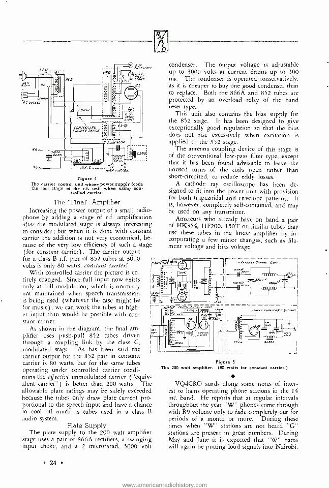
Figure 4
The carrier control unit whose power supply feeds the lazt stage of the r.f. unit when using con-
trolled carrier.
The "Final" Amplifier Increasing the power output of a small radio-
phone by adding a stage of r.f. amplification after the modulated stage is always interesting to consider ; but when it is done with constant carrier the addition is not very economical, be- cause of the very low efficiency of such a stage (for constant carrier) . The carrier output for a class B r.f. pair of 852 tubes at 3000 volts is only 80 watts, constant carrier!
With controlled carrier the picture is en- tirely changed. Since full input now exists only at full modulation, which is normally not maintained when speech transmission is being used (whatever the case might be for music), we can work the tubes at high- er input than would be possible with con- stant carrier.
As shown in the diagram, the final am- plifier uses push -pull 852 tubes driven through a coupling link by the class C, modulated stage. As has been said the carrier output for the 852 pair in constant carrier is 80 watts, but for the same tubes operating under controlled carrier condi- tions the effective unmodulated carrier ( "equiv- alent carrier ") is better than 200 watts. The allowable plate ratings may be safely exceeded because the tubes only draw plate current pro- portional to the speech input and have a chance to cool off much as tubes used in a class B audio system.
condenser. The output voltage is adjustable up to 3000 volts at current drains up to 300 ma. The condenser is operated conservatively, as it is cheaper to buy one good condenser than to replace. Both the 866A and 852 tubes are protected by an overload relay of the hand reset type.
This unit also contains the bias supply for the 852 stage. It has been designed to give exceptionally good regulation so that the bias does not rise excessively when excitation is applied to the 852 stage.
The antenna coupling device of this stage is of the conventional low -pass filter type, except that it has been found advisable to leave the unused turns of the coils open rather than short -circuited, to reduce eddy losses.
A cathode ray oscilloscope has been de- signed to fit into the power unit with provision for both trapezoidal and envelope patterns. It is, however, completely self- contained, and may be used on any transmitter.
Amateurs who already have on hand a pair of HK354, HF200, 150T or similar tubes may use these tubes in the linear amplifier by in- corporating a few minor changes, such as fila- ment voltage and bias voltage.
-1 f- ANrENNI 774N/N6 ON,
L. _ T
-= _ L./NER POWER SUPPLY UN/r J - - - - --------
- - - 4/NEAR AMPL/FiER C 8.61 LAW>
2mH R.641 66N- I
I I
II
11
I I
.00emAl JJF ,oag000r
Plate Supply The plate supply to the 200 watt amplifier
stage uses a pair of 866A rectifiers, a swinging input choke, and a 2 microfarad, 5000 volt
24
CS,/2 CSJPJ
Figure 5
The 200 watt amplifier. (80 watts for constant carrier.)
VQ4CRO sends along some notes of inter- est to hams operating phone stations in the 14 mc. band. He reports that at regular intervals throughout the year "W" phones come through with R9 volume only to fade completely out for periods of a month or more. During these times when "W" stations are not heard "G" stations are present in great numbers. During May and June it is expected that "W" hams will again be putting loud signals into Nairobi.
www.americanradiohistory.com

Sell- Excited Oscillators PART II, THE HARTLEY OSCILLATOR
In figure 1 is shown the fundamental Hartley oscillator circuit. The grid and plate are con- nected to the extremities of the tuned circuit. As Lg and Lp are parts of one tightly coupled coil, the relative a.c. grid and plate voltages are determined entirely by the placement of the variable cathode (ground) tap on the coil.
11111111111/1
C4
Figure 1
Thus moving the cathode tap on the coil over toward the plate end of the coil will cause a larger part of the a.c. tank voltage to be applied to the grid, increasing the a.c. grid excitation. The frequency is determined by the tank coil Lg,Lp, in parallel with Ct.
The Hartley oscillator is widely used in var- ious applications at all frequencies up to about 75 megacycles. When the higher C tubes are used it is often more desirable to use some form of the Armstrong above about 10 meg- acycles, but with the new tubes with very low interelectrode capacitances the Hartley has many advantages clear down into the ultra- short- wave region.
In figure 2 is shown a simple Hartley oscil- lator using series feed of the negative bias and the high voltage plate potential. In this circuit, as in that of figure 3, the negative bias is pro- vided by the drop across a grid leak resistor. Figure 3 shows a slightly -different series -feed version of the fundamental Hartley circuit. The circuit shown in figure 3 has the advantage that the tank inductance needs only be tapped and not split into two parts.
In figure 4 is shown the shunt fed version of the tuned -grid Hartley, or, more strictly: the "Feed -back oscillator ". This type is used
in autodyne receivers and test oscillators, but is
not used very much where large amounts of power are desired from the oscillator.
The circuit shown in figure 5 is quite sim- ilar to that of figure 4 but is termed the tuned - plate Hartley, or the "reversed feed -back os- cillator". It is subject to the same disadvan- tages as the oscillator of figure 4. The main ad- vantage of the oscillators of figures 4 and 5 lies in their simplicity and the fact that one side of the tuning condenser is at ground potential.
In figure 6 is shown the Meissner version of the Hartley. The main advantage of this os- cillator lies in the fact that there are no d.c. potentials on the tuned circuit, thus allowing one side of the tuning condenser to be ground- ed. This circuit used to be rather widely used in the oscillator circuit of superheterodyne re- ceivers, as it allowed one side of the trimming and padding condensers to be grounded and also allowed special precautions to be taken toward stabilizing the oscillator voltage output fed into the first detector over the tuning range of the receiver.
The simplest form of push -pull Hartley is that shown in figure 7. The plate voltage is series fed to the center tap of the plate tank coil while the bias voltage is shunt fed through individual r.f. chokes in each grid lead. The radio fre- quency feedback is ob- tained by the crossed Figure
grid leads, which are tapped on the tank coil. Adjusting the position of these taps varies the r.f. grid excitation. This oscillator is
highly useful and is much to be recommended for both communications and diathermy work.
In figure 8 is shown the Dow -Hartley, or the electron- coupled Hartley. It requires the use of a screen grid or pentode tube. The screen acts as a partial anode for the frequency- deter- mining portion of the circuit consisting of Lg,Lf and Ct. The load tank, which is usually tuned to some integral harmonic of the frequency - determining tank, is CLLp.
25
www.americanradiohistory.com
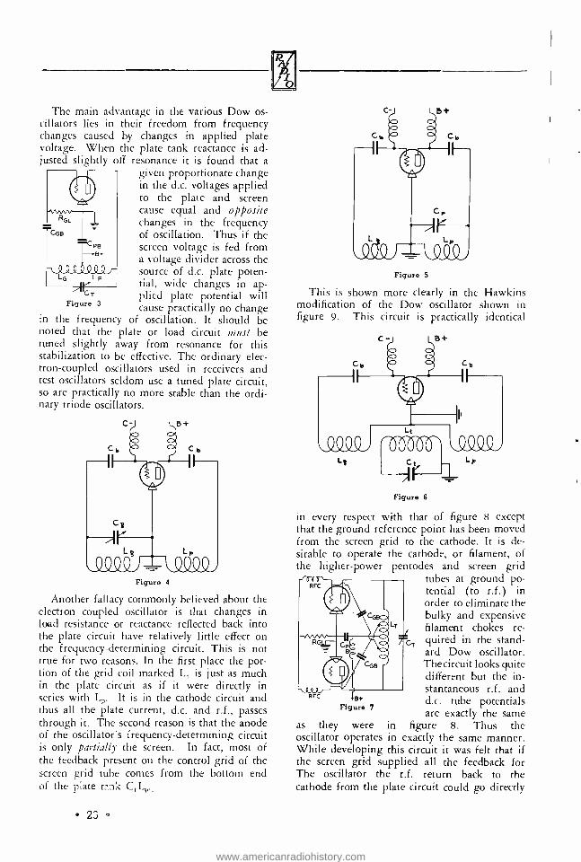
The main advantage in the various Dow os- cillators lies in their freedom from frequency changes caused by changes in applied plate voltage. When the plate tank reactance is ad- justed slightly off resonance it is found that a
given proportionate change in the d.c. voltages applied to the plate and screen cause equal and opposite changes in the frequency of oscillation. Thus if the screen voltage is fed from a voltage divider across the source of d.c. plate poten-
Lp tial, wide changes in ap-
CT plied plate potential will Figure 3 cause practically no change
in the frequency of oscillation. It should be noted that the plate or load circuit must be tuned slightly away from resonance for this stabilization to be effective. The ordinary elec- tron- coupled oscillators used in receivers and test oscillators seldom use a tuned plate circuit, so are practically no more stable than the ordi- nary triode oscillators.
RGL
._ nnn
CPB --.8+
AAA _
Figure 4
Another fallacy commonly believed about the electron coupled oscillator is that changes in load resistance or reactance reflected back into the plate circuit have relatively little effect on the frequency- determining circuit. This is not true for two reasons. In the first place the por- tion of the grid coil marked L,1 is just as much in the plate circuit as if it were directly in series with Li,. It is in the cathode circuit and thus all the plate current, d.c. and r.f., passes through it. The second reason is that the anode of the oscillator's frequency- determining circuit is only partially the screen. In fact, most of the feedback present on the control grid of the screen grid tube comes from the bottom end of the plate
23
Figure 5
This is shown more clearly in the Hawkins modification of the Dow oscillator shown in figure 9. This circuit is practically identical
Figure 6
in every respect with that of figure 8 except that the ground reference point has been moved from the screen grid to the cathode. It is de- sirable to operate the cathode, or filament, of the higher -power pentodes and screen grid
tubes at ground po- tential (to r.f.) in order to eliminate the bulky and expensive filament chokes re- quired in the stand- ard Dow oscillator. The circuit looks quite different but the in- stantaneous r.f. and d.c. tube potentials are exactly the same
they were in figure 8. Thus the oscillator operates in exactly the same manner. While developing this circuit it was felt that if the screen grid supplied all the feedback for The oscillator the r.f. return back to the cathode from the plate circuit could go directly
as
www.americanradiohistory.com

back to the cathode or ground point. This would allow one side of the plate tuning condenser to be grounded. However, it was found that the circuit would n o longer oscillate when loaded, as the screen current would drop down to a very low value as soon as the Figure 8
plate voltage was applied. The circuit would oscillate well as long as there was no plate volt- age applied but as soon as the plate voltage was applied some extra feedback from the plate cir- cuit had to be applied to the feedback portion of the grid coil in order to keep the circuit
oscillating. Thus neither side of the plate coil is at ground potential, with re- spect to r.f., and it is highly desirable that link coupling rather than capacitive cou- pling be used be- tween the plate cir- cuit and the load.
at The circuit shown in figure 10 differs
from that shown in figure 9 only in the method of feeding the d.c. voltage to the screen grid and plate. In figure 9 shunt feed is shown and in figure 10 series feed is used. The resistor R, which is dotted in figure 10 is only necessary if it is desired to use a voltage divider rather than a series dropping resist- or in order to obtain screen voltage from the plate power supply. The dropping resistor is
satisfactory for most applications, though if the oscillator is keyed the voltage divider minimizes keying chirps.
L
+SG
Figure 9
Figure 10
In figure 11 is shown the simplest form of Hartley oscillator for use on the ultra high fre- quencies. This oscillator is stabilized by means of a resonant line type of tank circuit which is
characterized by low losses and a high circuit "Q ". This means that the oscillator resists
V I O
changes in frequency caused by changes in tube voltages or loads, and it is becoming more widely used every day.
The tubing which com- prises the tank circuit is approximately a half wave long, less the effect of the capacity loading caused by tapping the tube elements on the tubing. The grid tap on the tubing is var- ied in order to adjust the grid excitation. In gen- eral the Armstrong or "tuned -grid- tuned -plate" type of rod- stabil- ized oscillator has certain advantages over the Hartley version and will be described in a
later article. In figure 12 is shown exactly the same idea
as in figure 11 except that a conventional tank coil is used in place of the resonant rod or tube. This type of oscillator is often used at the very low audio frequencies in order to get good sine -wave output from the oscillator. It is simply an expedient to get high Q in the tank circuit without the use of high C.
In figure 13 is shown the common "unity-cou- pled" oscillator. This practically amounts to a
push -pull Hartley with the grid taps out on the ends of the plate coil. The use of two coils, one inside of the other, is simply to a l l o w
series feed of both the grid and plate voltages. The tank circuit often consists of copper tubing for the plate circuit with insulated wire thread- ed inside of the tubing for the grid coil. This circuit is very critical to adjust due to the fact that there is no means of adjusting the grid excitation. Thus it is efficient and stable only when low p. tubes are used as oscillators. The plate voltage and the load must be very care- fully adjusted so that the tubes receive just the right amount of grid drive for the load used.
The plate efficiency of this type of oscillator is usually quite low and about its only justifi- cation is simplicity.
There are other types of Hartley oscillators, but the foregoing includes practically all of the important ones. [Continued ran rage 951
PB
27
www.americanradiohistory.com

"H eLL and 1 I isI, Water By ROBERT S.
During those terrible days in March when 15 eastern states were torn by flood and storm, heroism became commonplace. The last efforts of staggering body and exhausted mind were given freely in selfless aid -not a few times here and there, but thousands of times. There was no hero of this disaster ; there were (with- out a word of exaggeration) ten thousand heroes.
There were, of course, also mean, selfish and thoughtless men. There were looters, and on the whole they seem to have reaped swift ven- geance from people too harried to tolerate thieves. There were idiots whose witless cur- iosity brought their cars into highways needed for urgent transportation. There were selfish people who needlessly used the dwindling sup- ply of food, water and gasoline.
But on the whole the human race need not be ashamed of its showing in the floods of 1936. No age, nor sex, nor trade, nor organ- ization can with any fairness claim special dis- tinction in this matter. It would be silly and conceited to do so. We turn to amateur radio's part only because that is our own special field - and not with any thought that it deserves one word of praise over that due those brave people who, organized or individually, fought disaster and who now are engaged in the last portion of the thankless and often horrible task of or- dering and rebuilding.
Radio's Part By common consent it was early in the emer-
gency acknowledged that communication must be kept open at all costs. Limited supplies of fuel and oil were, beyond the uttermost neces- sity, made available to communication com- panies to permit them to carry on the tradition of communication, to keep the circuit working. More than a few telephone exchanges operated with fire engines pumping water out of the building as it seeped through sandbags frant- ically piled by volunteers. Those fire engines worked in flooded streets, sometimes jacked up onto hasty platforms and served by hip - booted men. In a few cases their fuel came by boat. The operators kept up the tradition of the service, as did the line and inside men. Sometimes the service went under for a few hours, but not for long. Usually some lines
28
KRUSE
11
went to work again soon. That is not the story of a town ; it is the
composite story of a hundred towns in 15 states. Emergency power was provided by storage batteries from automobiles now useless in flooded streets. All manner of charging equipment was rigged up. One town used an old street car motor driven by a discarded auto engine, the whole thing being on a garage roof, out in the pounding rain and tearing wind with two half- drowned men taking turns keeping it running more or less.
The telegraph firms did as well ; the rail- roads performed their own special sorts of mir- acles; and by no means forget the truck driver, the policeman, the coast guard -who went 50 and 60 miles inland on rivers not ordinarily navigable and now armed with every type of floating danger -nor the medical services, nor...
But ours is a story of communication, and we will stick to that. The broadcast stations, sup- ported by strenuous efforts of the power corn - panies, did inspiring service in directing aid, quieting rumors, issuing warnings, and other- wise removing the terror of uncertainty. Again it would be unfair to name any one station, for this would manifestly be the rankest in- justice to some other station. They all, manage- ment to assistant operators, may look back with quiet pride.
Most commercial radio services had less opportunity to do things outside the usual order of business, and beyond an increase in the emergency type of message their work went along regularly insofar as power -supply per- mitted. The communication system of the police and military organizations carried a sim- ilar increase of load without any actual neces- sity for a swift change of procedure such as the broadcasting stations so magnificently ac- complished.
For the amateur radio station it was alto- gether another matter. Here was no network of telephone wires with which auxiliary commun- ication could be accomplished and procedures of broadcasting changed. Instead each station was referred pretty largely to its owner's in- itiative and good sense, with whatever cooper- ation he might through good fortune get from
www.americanradiohistory.com

the power company, the local police and the city fathers. This cooperation was not by any means always forthcoming. For instance: Mr. Gerald Coleman of W8FRC was denounced as the author of a dam -bursting rumor and ordered to stop transmitting. It is interesting to note that the news commentator, Boake Carter, at his next broadcast whole heartedly condemned the city for this action, defended Coleman's stand in staying on the air on the ground that his license was federal and not local, and as- serted stoutly that Coleman's transmission of the information was based on information not original with him but being shouted about the streets before W8FRC mentioned the matter.
Beyond that all the stories that have ever been told about emergency amateur radio could be repeated with different names and calls at- tached to them. None the less it would once more be silly and unfair to do this, since every band, voice and c.w., was alive with emergency amateur radio work, and it is far more fair to name no names at all than to list a hundred or two and overlook others of whom one does not happen to have heard, or who have not been willing to report their work for fear of appearing immodest.
At RADIO'S eastern laboratory, quite literally hundreds of stations were heard doing their very best to help. Not all of them were doing it usefully; some were frantically calling for someone to send them emergency messages, and in so doing were causing far more harm than good. But on the whole, interference was much less than one might think. Stations got off the air promptly when asked to. During one afternoon when the air seemed clear a test was being sent to RADIO by a manufacturer in ac- cordance with a schedule previously arranged. That test never was finished; it went overboard for keeps as soon as a flood- distress station asked for the channel. There has been some "grousing" about amateur radio stations serv- ing (as many did) to transmit news to papers. I do not share the opinion that this was harm- ful. It was much better for distressed relatives outside to know what was going on. Not all the anxiety was in the flood territory.
The Naval Radio Reserve and the Army - Amateur network both did excellent service, yet the finest thing about the whole participation of radio in this awful business was the ability of amateurs to use their stations intelligently, to turn with the need of the hour on their own initiative and with nothing but their own
good heads and hearts to guide them. For once it was possible to believe that amateur radio really has the emergency value of which we have heard so much.
Not a very large part of all this was in the form of "message traffic ". There was often no time to contort urgency into dry messages, but the facts got through, even though a "traffic total" will never be possible. Some even helped, and helped greatly, without touching key or microphone. They aided other stations to keep on the air; they helped to receive or they stayed out and let the track remain clear. Even remote districts helped in this way.
Amateur radio "came through" in time of stress. For such an exhibition of performance under fire, we can, as a group, feel justly proud. The individual amateurs who so nobly responded and endured danger, privation and physical hardships for the sake of the public will not all receive public acclaim and glory. Theirs must be the reward of unsung heroes; the satisfaction that results from a job well done, the inner glow that comes only from unselfishly helping our fellow men.
W2HNX offers the following suggestion: "In my box of tools, I include a pair of six -
inch forceps. I find it the handiest tool I've ever used. The jaws are notched or knurled for a good grip. I bought them some years back for 50c at a chemical supply place and they are known as flesh forceps (otherwise an overgrown tweezer) . They are far better for holding wires when soldering than pliers, as the latter are sometimes too large for tight places. Being long enough, the fingers are seldom toasted by the iron. When it comes to retrieving a lost screw or nut from a narrow spot, nothing like this tool does the job so well. As for putting a nut on a screw in a tight place, these forceps are par excellence. For every time I use the pliers (and I have nearly a half dozen kinds) I use the forceps twice."
Our foreign correspondents report that it is
almost impossible to raise "W" phones by answering their CQ's. Apparently the United States amateurs do not listen outside their own phone band after a CQ, with the result that foreigners operating phones in other sections of the band are not heard. There seems to be little trouble in maintaining schedules with "W" stations in the 14 mc. band, but for- eigners seldom raise a "W" after calling him.
29
www.americanradiohistory.com

Notes on M u[tívíbrator Adjustment By BERNARD EPHRAIM *, E.E.
Numerous inquiries have been received by the writer regarding the "Harmonic Oscillator" appearing on page 292 of the 1936 edition of the Radio Handbook. The following notes have been prepared with a view toward clarifying the complexities of the circuit.
Frequency Determination The fundamental frequency of the multivi-
brator cannot be determined from formulae em- ployed in determining frequency in other types of oscillatory systems. However, the fundamen- tal frequency may be closely approximated by computing the relaxation -oscillation time con- stant of the system. The constant may be de- termined from the following equation:
V, T-RC log -
V2
where C is the total capacity in the circuit; R, the total effective resistance in series with the capacity; and V, and V2 the initial and final voltages, respectively, across the condenser.
Another method for calculating the frequency of the system, while not as accurate as the above, consists of simply taking the CR product of the grid circuits. Expressions for calculating fre- quency by this method are:
F --
F
1
(C,+C2)R L
(R, +R_)C where F is the frequency in cycles; C, the ca- pacity in farads; and R, the ohmage of one of the grid leak resistors.
Applying one of the above equations, take the following example:
If a multivibrator had grid leak resistors of 20,000 ohms each, condensers of 500 micro - microfarads each, the frequency could be deter- mined by the following solution:
F = 1
(C, + C2) (R)
*Editor, the Radio Handbook, San Francisco.
30
1
(500 + 500) (20,000)
1 1
(10-9) (2 x 10⁴)
1
.00002
2 x 10-a
-- 50,000 or 50 kc.
Note on Technique: To find the value of the grid leaks for some specific frequency when the value of the condensers is known, use the fol- lowing method.
(1) Take the frequency in cycles and divide into 1; this gives the time constant in seconds.
(2) Divide the time constant by the sum of the condensers in farads; the result gives the value of each grid leak resistor in ohms.
Synchronizing Technique Prior to entering into these notes, it may in-
terest the reader to learn that the conditions under which synchronism occurs differentiates the multivibrator from other types of oscillatory systems. In the case of the multivibrator the phenomenon of "resonance" is completely ab- sent; hence, no "drawing effect" of forced syn- chronization takes place as the multivibrator fre quency approaches the control frequency. An- other point of difference is that the "band width" of the relaxation frequency is approx- imately an octave wide; this unique property permits synchronization to occur anywhere over the octave region.
There are many methods by which it is pos- sible to synchronize a multivibrator with an ex- ternal controlling device. Of the miscellaneous technique involved, the most practical and satis- factory procedure of insuring positive control is given below. Before proceding, the following preliminaries should be observed:
(a) It is prerequisite that the frequency of the multivibrator be slightly lower than that of the controlling device.
(b) It is not practical to synchronize with harmonics much greater than 15 times the fun- damental of the multivibrator.
(c) The control device (if any) regulating the magnitude of the injected control voltage
www.americanradiohistory.com

should be advanced to approximately the half- way point before synchronizing.
(d) If the injected voltage is too low, the multivibrator will not fall into step with the controlling frequency. Low control voltage can be detected after an attempt is made to syn- chronize by simply rotating the condensers in the multivibrator over a small arc of normal setting. If the frequency remains stable during this manipulation, the voltage is of the proper magnitude. On the other hand, if the frequency should "wobble" or "creep" (not jump to a higher frequency) the control e.m.f. must be raised to a higher value.
Synchronizing at Fundamental Frequencies: To control the fundamental of the multivibrator proceed as follows:
(1) With an oscillating receiver or heter- odyne wavemeter, pick up the controlling fre- quency with the multivibrator turned "off" and note the strength of two successive harmonics on the detecting apparatus.
(2) Carefully adjust the receiver to zero -beat with the controlling frequency.
(3) Turn "on" the multivibrator. (4) Now, by varying the control of the os-
cillating receiver or heterodyne through two pre- vious harmonic settings, an appreciable increase in the strength of the harmonic points should be detectable. No other carriers should be heard between the respective harmonic settings; if there are any present, simply vary the control voltage or rotate the condenser setting on the multivibrator until the unwanted carriers are eliminated. When the proper condition is rec- ognized, it is possible to rotate the condenser setting over a small arc of control without in- troducing any changes in the fundamental fre- quency.
Synchronizing with Harmonics of the Multi - vibrator: To control the multivibrator by an integral harmonic of its fundamental, first, ad- just the values of the condenser until the relax- ation- frequency is approximately equal to some submultiple of the controlling frequency, then proceed as follows:
(1) With an oscillating receiver or heter- odyne wavemeter, pick up the controlling fre- quency with the multivibrator turned "off" and record the position of two successive harmonics heard on the detecting apparatus.
(2) Turn "on" the multivibrator. (3) Vary the control on the receiver or het-
erodyne between the two harmonics noted and count the number of carriers heard including
0
the first and second harmonic points. The num- ber counted should be exactly equal to the num- ber derived by dividing the control frequency by the relaxation -frequency. When this con- dition is obtained, the system is synchronized with the harmonic selected.
(4) To test the stability of control, vary the condensers on the multivibrator over a small arc of normal setting while listening in on the re- ceiver or heterodyne. No excursions in fre- quency or changes in harmonic count should be detectable between the settings previously recorded.
Ambulances Now Radio Equipped A new use for radio communication facilities
will be inaugurated in Evanston, Ill. when Gen- eral Electric engineers equip one of the city's ambulances with short -wave transmitting and receiving apparatus, enabling doctors to keep in immediate touch with police and hospital of- ficials. The ambulance radio equipment will be part of a two -way radio system also to be installed in 10 Evanston police prowl cars.
During a police chase or in an emergency in which the ambulance is used, if the driver of the radio car desires to get in touch with police headquarters or the hospital he will mere- ly lift a telephone from a hook on the instru- ment panel, and a 15 -watt transmitter mounted in the car will go on the air, putting him in immediate touch with headquarters.
Valuable time can be saved in relaying word ahead to the hospital regarding the condition of a patient, whether or not to have the oper- ating room in readiness for quick use on ar- rival, or the summoning of special doctors, all of which now must await the arrival of the ambulance at the hospital.
Fifteen -watt transmitters and suitable receiv- ing equipment will be installed in the ambu- lance and prowl cars. Mobile transmitters and related motor -generator power -supply units will be concealed in the cars, while the receivers will be located like conventional auto sets under the cowls. A 15 -watt transmitter and receiver will be located at headquarters.
One contemporary monthly has raised the question of which name should be applied to the instrument, test oscillator or signal gener- ator. We are inclined to think, in view of the inroads made by slang and monosyllables, that time will take care of that. Hasn't electricity become juice; radio - frequency, soup, and so on?
31
www.americanradiohistory.com

LOW LOSS
By J. N. A. H
The recent development of relatively inex- pensive high voltage transmitting tubes with quite low interelectrode capacitances allows very high plate efficiencies. Class C plate efficiencies of 75 to 85 % on 14 megacycles are easily possible, and plate efficiencies between
Figure 1
A well- designed tank coil: good form fac- tor and minimum of supporting material.
66% and 80% are attainable on 30 mc., by using low C tubes, high plate voltage, and low loss tank circuits.
Tank circuit losses still can be quite high unless precautions are taken to minimize coil loss and corona loss at the high frequencies. The first step toward obtaining high plate effi-
ciency is to use the proper value of L to C ratio in the final amplifier plate tank circuit. The formula for determining the required tank capacitance is:
520,000 Q C=
f.K.Rb where C is the required capacitance of the tun- ing condenser in micro- micro -farads; Q is the Q of the circuit (5 for c.w., 10 for phone, and 15 for self- excited oscillator use) ; f is the fre- quency of operation in megacycles; K is a con- stant (K is 1 for single -ended grid neutralized, K is 4 for single -ended plate neutralized, and K is 6.6 for all push -pull amplifiers) ; and Rb
is the d.c. resistance of the plate to filament path of the amplifier. In other words, R equals d.c. plate voltage divided by d.c. plate current (in amperes) of the amplifier.
The table shows various values of C at
32
Tank Circuits AWKINS, W6AAR
ferent frequencies and plate voltages and for the three different types of amplifiers: single - ended grid neutralized, single -ended plate neu- tralized, and push -pull. Note that the table gives the capacitance required for phone oper- ation only.
For c.w. use divide the indicated capacitance given in the table by two, and for use in a fairly stable, self- excited oscillator multiply the in-
dicated capacitance by 1.5. The indicated capacitance is that which
should be in the circuit when tuned to reso- nance at the operating frequency, not just the maximum capacitance of the tuning condenser. The tank coil should be pruned so that the circuit resonates with approximately the re- quired amount of tank capacitance. The stray
Figure Split- stator condenser 100 µµíd. per section,
2
of new design, 1500 volt rating.
wiring and tube capacitance can be subtracted from the total capacitance indicated in the table in order to determine the tuning capacitance. However, the stray circuit capacitance is rarely large enough to affect matters except at the ultra high frequencies.
The best test for the L/C ratio of a tank circuit is slowly to tune the tank through reso-
dif- nance, meanwhile observing the output or an-
www.americanradiohistory.com

D.C. Plate Volts
Eb
D.C. Plate
Amps. (Loaded)
1p
PLATE
Grid Neut. Plate Tank Cap.
Cgn
TANK Plate
Neut. Plate Tank Cap. CI,
CAPACITANCE
Push Pull
Plate Tank Cap.
Cpp
FREQUENCY BAND
FOR PHONE D.C. Plate Volts
Eb
D.C. Plate
Amps. (Loaded)
1p
USE
Grid Neut. Plate Tank Cap.
Cgn
Plate Neut. Plate Tank Cap.
Cpn
Push Pull Plate Tank Cap.
Cpp 375 .025 200 50 30 1500 .100 200 50 30 375 .050 400 100 60 1500 .200 400 100 60 375 .100 800 200 120 1500 .400 800 200 120
1750 KC. 750 .050 200 50 30 3000 .100 100 25 15 750 .100 400 100 60 3000 .200 200 50 30 750 .200 800 200 120 3000 .400 400 100 60 375 .025 100 25 15 1500 .100 100 25 15 375 .050 200 50 30 1500 .200 200 50 30 375 .100 400 100 60 1500 .400 400 100 60
3500 KC. 750 .050 100 25 15 3000 .100 50 13 8 750 .100 200 50 30 3000 .200 100 25 15 750 .200 400 100 60 3000 .400 200 50 30 375 .025 50 13 8 1500 .100 50 13 8 375 .050 100 25 15 1500 .200 100 25 15 375 .100 200 50 30 1500 .400 200 50 30
7000 KC. 750 .050 50 13 8 3000 .100 25 6 4 750 .100 100 25 15 3000 .200 50 13 8 750 .200 200 50 30 3000 .400 100 25 15 375 .025 25 6 4 1500 .100 25 6 4 375 .050 50 13 8 1500 .200 50 13 8 375 .100 100 25 15 1500 .400 100 25 15
14,000 KC. 750 .050 25 6 4 3000 .100 13 3 2 750 .100 50 13 8 3000 .200 25 6 4 750 .200 100 25 15 3000 .400 50 13 8
tenna current and the d.c. plate current. Max- imum output r.f. current should be obtained at the same tuning point as minimum d.c. plate current. If they do not coincide, there is too much inductance and not enough capacitance in the circuit. If there is too much capacitance in the circuit the minimum unloaded plate cur- rent of the amplifier stage will not go down low enough when the antenna or load is dis- connected from the amplifier. The minimum unloaded d.c. plate current should drop to less than 10% of the normal loaded value, if high plate efficiency is to be obtained. For a some- what more complete discussion of the L/C ratio in a tank circuit see RADIO for September, 1935, page 22.
Tank Coils About the best tank coil that can be made,
at the present time, uses either one -eighth
inch copper tubing or large copper wire sup- ported by thin strips of celluloid, Victron or Mycalex. See the coil of figure 1. These coils are wound on a wooden form which is removed after the cement which holds the wire to the supporting strips hardens. The old tank coils made of large copper tubing are found to have materially more loss resistance than the newer, wire -wound coils, and the larger sizes of wire will easily handle the required circulating cur- rent without excessive heating. The better wire -wound coils use steel -core copper wire to minimize changes in inductance with changes in temperatures and also to provide greater me- chanical strength.
The length of the best coils will be about 1.5 times the coil diameter. Theoretically a "square coil" with length equal to diameter has a slightly better form factor, but this is offset
33
www.americanradiohistory.com

by the longer leads which must be used with a
"square" coil in order to keep it farther away from its associated tuning condenser. However, coils with a length twice the diameter are quite satisfactory. The coil should be kept away from metal chassis and breadboards in order to avoid induced losses, and care should also be taken to keep the fields from two coils in the same transmitter from interlocking and pro- ducing undesired feedback and two -spot tun- ing. If the coils are designed to plug in for band changing, care must be taken to use large and well -fitting plugs and jacks to avoid losses at the coil terminals. Only a fraction of an ohm of series resistance can cause a material loss.
R. F. Leads The connecting leads in the tank circuit
should be, where possible, of eighth -inch cop- per tubing and all joints should be soldered. The leads, both in the tank circuit and from the tube terminals, should be as short as it is
humanly possible to make them. It has been found that cutting as little as one inch off the plate lead in a 28 mc. amplifier has cut the unloaded d.c. plate current in half. Plate and grid leads have appreciable inductance and capacitance and these stray reactances have a
surprising effect on the higher frequencies. They often have a very disturbing effect on the neutralization of the circuit.
Tubes For amplifier use at the high and ultra -high
frequencies there is no such thing as a tube
with too -little interelectrode capacitance. The less, the better. Note that the really important interelectrode capacitance in a vacuum tube which adversely affects the operation of the
circuit is not the grid -to -plate capacitance, but the input and output capacitance (the grid -to-
ground and the plate -to- ground capacitances). Of course, the plate -to -grid capacitance has a
small effect on the input and output capaci-
tance, when a stage is neutralized, but the other two capacitances have much more effect on the
circuit. Above 7 megacycles, the mechanical layout
of the amplifier has much more effect on its
losses than has the electrical circuit. It does not make much difference whether grid or plate neutralization is used. Use the type of neu-
tralization which allows the shortest r.f. leads
to be used. Sit down and study all your parts before starting construction. Move the tube, coils, and condensers around and visualize
34
where the hot leads are going to go. A little study of this kind will make a great deal of difference in the output and efficiency and is
much more worthwhile than arguing over the relative merits of various neutralizing scheme or split- stator condensers.
The rules for obtaining high efficiency and output can be summarized as follows: Short plate, grid, and tank leads; heavy, solid, and direct conductors (avoid stranded leäds) ;
enough "C" to allow sharp tank tuning, load- ed; enough "L" to allow unloaded plate cur- rent to drop to 10% of loaded value; high plate voltage; filament voltage at rating or 5 %r
high; high bias and excitation; perfect neu- tralization without degeneration. )Photo, eourtrs) Decker- Mfg. Co. and Audio Product, Co.)
REPEL THE INVADERS It is well known that commercial stations of
various nations hope someday to divide up the present ham bands. For some time commer- cial stations in Europe and in the U.S.S.R. have been consistently operating in the 160 and 75 meter bands. The longer we let them sit there the harder it will be to dislodge them.
The following stations have been logged in
the amateur bands and every ham should try to log them with time, date, character of trans- mission, etc. These reports should be turned in either to RADIO or to QST. care Mr. F. E. Han- dy.
VP3MR on 7080 kc British Guiana JAX 7285 Japan JEHO 7120 Japan JAY 7200 Japan XGJ 7070 China? EA8AB 7200 Spain CR6AA 7177 HB9B 3770, 7022, 14,044 kc XU5X 14,300 XE1EX 3880 ORZY 14,150 K1OAB 7005, 14,010 DZH LZA
ship ship ship
There are undoubtedly many more such sta- tions handling commercial traffic in the amateur bands. The point is that a definite record of all such illegal transmissions must be placed in the hands of the government before it can pre- sent an official complaint to the country con- cerned.
The chimes used at CFAC in Calgary as sta- tion identification are the corresponding notes on the scale, C, F, A, C.
www.americanradiohistory.com

A Compact Kilowatt By JAYENAY
There are liter- A simple and economical one kilowatt c.w. transmitter capable ally hundreds of of 750 watts output on 10, 20, 40 and 80 meters. Total overall different one kil- owatt
less than $200 without meters.
c.w. transmitters (composite) scattered all over the world and no two of them are alike. All, by definition, can be made to draw a kilowatt input from the final power supply. In some cases the actual power output on the fundamental frequency may be 900 watts; in others it may be only 500 watts. All of them represent, in some measure, some form of sci- entific achievement. However, it should be emphasized that there is a wide difference be- tween a scientific achievement and an engineer- ing achievement. The scientist tries to get the best possible result. The engineer, on the other hand, tries to get the best result at a reasonable cost. Until costs are taken into consideration one is not dealing with practical engineering but with purely academic science. All of us have dreamed, at one time or another, about our own pet idea of the perfect transmitter. However, if dreams are to come true, then idealism must be tempered with considerable practical cost accounting.
The transmitter shown herewith actually cost $187.75 to build. This is the cost of the parts including hook -up wire, breadboards, and all the miscellaneous bits of hardware that usually never get counted. These are Pacific Coast prices. All of the parts were bought new at retail and these costs should be duplicated any- where in the U.S.A. Even to play it safe and allow for shipping charges to out of the way localities, $200 is the absolute top. $17.50 was allowed for the high voltage plate transformer, a conservative allowance. You can wind your own for about $7.50; you can get another ham to do it for about $12.50; or you can buy a new one for about $15.00. In this particular transmitter the plate transformer was a 2 kw. pole transformer purchased from a junkman for $5. In many cities the standard price for second- hand pole transformers averages about $1.50 per kilowatt of capacity. Incidentally, don't pick up a pole pig of less than about 2 k.v.a. capacity as most of the second -hand ones of from 750 to 1500 watt capacity will have such poor voltage regulation that bad key thumps will be produced. If a new transformer of
standard make is purchased it should be able to
give 400 ma. at 3300 volts (6600 center tapped) .
The rig is simple and standard practice throughout. It starts out with a 6A6 oscillator - doubler in the regular Jones exciter. As the low voltage power pack acts also as the bias supply for the buffer and the final stage, note that the filament of the 83 low voltage rectifier is grounded. Thus positive is grounded and negative is "high ", which puts the cathode of the 6A6 about 350 volts above ground. Thus it is a good idea not to ground the 6.3 volt heater winding on the 6A6 directly, although a .01 l.tfd. mica bypass will help to eliminate any noise in the receiver when the key is up. The oscillator portion of the 6A6 is keyed in the B plus lead, as any transmitter without full break -in in this day and age is old fashioned.
Capacitive coupling is used into the doubler portion of the 6A6, and it is a good idea to double on all bands, even 80, as it helps to eliminate keying chirps arising from feedback from the buffer and final stages into the oscil- lator.
The doubler portion has about 10 watts out- put on 80, doubling from 160; about 8 watts on 40 ; about 7 watts on 20 ; and about 5 watts on 10 meters. On 10 meters it is desirable to use one of the new 20 meter crystals, as the 6A6 gets very "unhappy" when operated as an oscillator and quadrupler from a 40 meter crystal. It can be done with regeneration and it has been done, but requires considerable jug- gling.
The doubler is link coupled to the 50T buf- fer, which operates on the same frequency as the final amplifier. Several hams who have built similar rigs using a 50T to drive two 150T's or 354's make two bad mistakes and then find themselves shy on excitation to the final stage. First, they run the 50T on 1000 or 1500 volts instead of the full 2500. Re- member that the potter gain through a tube goes up very fast as the plate voltage is raised. Then the second bad mistake is to use too much bias on both the buffer and the final amplifier. The buffer must be operated for maximum power gaits and not maximum plate efficiency.
35
www.americanradiohistory.com

RFC
507 HK354
-350
115V. A.C.
68A 66A
3300 ,3300
ráb)
C1-.01 µfd. paper C2-75 µpfd. midget C3--100 µµfd. mica C4 -100 lipid. per sec-
tion, 2000 volt spacing
Ca -Two 4" square plates, variable gap
The General Wiring Diagram Ci¡-.002 7500 volt
mica C7-50 µµfd., 6000 volt
spacing Cs -150 ¡gild. per sec-
tion, 3500 volt spacing
C4-100 mild. per sec- tion, 7500 v o l t
Therefore its grid bias should be just "cut -off" and no more. Also, the final stage should not be biased beyond twice cut -off. Even at 1.2 times cut -off the power output was over 700 watts with a kilowatt input (20 meters). There is just about enough output out of the 50T to allow proper excitation of the final stage (75 grid ma.) through twice cut -off bias. The im- portant point is that the bias on the final stage should be just enough to allow 65 to 80 grid ma. to flow. It is much better to run at low bias and proper grid current than high bias and very low grid current (neutralized amplifier working on fundamental) . Grid neutralization is used on the buffer to allow a somewhat cheaper plate tank condenser to be used and still keep the fixed neutralization advantage of the split stator condenser type of tank. Grid neutralization also eliminates any tendency to- ward the degeneration which robs so many plate neutralized split- stator stages of a good deal of their available excitation. The buffer is link -coupled to the final amplifier and the final stage is link- coupled to the antenna cou-
36
spacing Cin-8 Rid. electro-
lytic C11 -2 µfd., 3 0 0 0
working volts R1-400 ohms, 10
watts R.- 50,000 ohms, car-
bon
R:I -3000 o h in s. 50 watts
Ra- 100.000 ohms, 103 watts
R -, -5,000 ohms, 50 watts
CH1 -30 hy., 150 ma. CH.2-5 -25 hy. 400 ma.
swinging choke
pler, which may feed any type of antenna. Incidentally, the tubes in the final amplifier
could just as well go in parallel instead of push -pull with some slight reduction in overall cost. The 354's have such low shunt input and output capacities that they can be paralleled even on 10 meters without any particular dif- ference in operation, except for the increase in even harmonics in the output.
However, as even harmonics are becoming quite troublesome and as the F.C.C. is sending out a large number of discrepancy slips for this reason each month, it was decided to use push - pull.
There is very little else about the rig that needs much comment. The circuit diagram should be self -explanatory.
Don't forget to keep all grid and plate leads as short as it is possible to get them. A three inch lead on 10 meters is too long, and there is no excuse for it where the grid and plate leads are as highly accessible as they are in most of the newer high frequency tubes.
www.americanradiohistory.com

Investigating Committee Minority Report At the request of many amateurs interested
in the policies of amateur radio, we reproduce herewith the minority report of the commit- tee (consisting of New England's Bailey, Chair- man, Hudson's Hill, and Central's Roberts) which was appointed at the last meeting of the A.R.R.L. Board of Directors to investigate the many charges against the League's administra- tion which have been made by a large number of amateurs, both in clubs and as individuals, and which have been brought to public light by RADIO and R /9. The majority report (a "white- washing" affair) has, for some unknown reason, been copyrighted and therefore is not repro- duced here.
MINORITY REPORT By E. A. ROBERTS*
Director, Central Division, A.R.R.L. It might have been assumed that the Investigating
Committee, appointed by the Board at its last meet- ing, was competent to make a thorough investigation. The report which the Board has received from the two other members of the committee, does not show it came from "super- investigators" and I believe it will be challenged by the amateurs at large when it gets into circulation. Both the majority and minority reports should be available to the membership on re- quest, and this minority report will not be copy- righted.
The majority report shows that they just made a "pass" at an investigation and then "ran out ". The criticism that will follow this report as "not worth a rap" will be discouraging to the two signers, and will be just like a little breeze that peeps into a calm spell, but which ends up as a regular "he" cyclone.
The chairman} got off on the wrong foot by taking a sunerior attitude that he was the only one to be heard and considered -also did the other member of the Committee who wrote, "Roberts, keep your temper" in reply to my endeavor to get the investiga- tion started.
My first letters to Baileyt went unanswered, and my later letters, calling for certain investigations, were ignored if he was not in accord with the con- tents, claiming that he had not received them.
The chairman seems to have been willingly in- fluenced by his close friend the Secretary. It is my impression that Warner was kept advised of what was going on in the committee meetings. It was stated by some leading amateurs that the entire inves- tigation would end in nothing more than a "white- wash of Warner" and you can now form your own conclusions as to whether it is or not.
You might ask the question -who was the member of the Investigating Committee who went to Hart- ford before the committee meeting of August 30 -31, 1935 in Cleveland, and spent the day and night with
*WSHC, 2699 Endicott Road, Shaker Heights, Cleveland, O.
fG. W. Bailey, Chairman of the Investigating Committee, 74 Webster Road, Weston, Massachusetts.
Warner, and what was the object of the visit? Also, at the meeting of the committee held at the Hartford headquarters -why was my portfolio handled while I was out to lunch and what was the motive?
Now for the majority report. The report shows a change in date on Page 13, from December 1935 to February 17, 1936. This would indicate that the re- port was mimeographed about three months ago. The work was done at Headquarters and written by Sec- retary Warner from notes offered by Chairman Bailey, and some of the recommendations I made were de- leted, although I understood they were to be included in the report, if I signed it. If my signature had been attached to the report it could then have been sent out, as "hunky- dory" and the "boon -doggling" would then have been complete.
I wrote Chairman Bailey that I thought we were going to have some difficulty over Warner's salary, as I could not agree to any $12,000 figure and I be- lieved that the amount should be reduced to $7200 - as that is all he is worth. He will never get another kilocycle for the amateurs and more frequencies is what interests the amateur.
First portion of report, "Analysis of Article by Foster' in the Magazine Radio" ; I wanted the name of Foster deleted= because there was no sense in at- tacking Foster when he was not here to answer the charges. I consider this unfair. If it was still neces- sary to answer Foster's statements made against War- ner, it would have been just as effective to refer to the former Radio articles.
I recommend that the chief paragraph regarding Mr. Hebert be deleted entirely and the following be substituted:
Therefore the committee recommends that Mr. Hebert be relieved from further duties in the field, as he has requested with the commendation of the Board for the more than twenty years of faithful service he has rendered to the League, and that he continue his duties as office- manager and credits and collection manager at Headquar- ters, and that his present salary continue unless changed by the Board at the next meeting.? I wrote Bailey: I believe the Communications De-
partment of the League should take charge of the field contacts but would not insist upon it if it was not sustained; I am willing that it be taken over by the Secretary, but not by the assistants. I believe the Secretary and other heads of departments should get out into the field and represent the League. If we are going to create a better understanding throughout the country among the amateurs, we have got to use the best and most influential representatives we have at Headquarters.4
[Continued on Page 91]
IThe late Colonel Clair Foster, W6HM, gentleman, ham, and the grand old fighter of and for amateur radio.
=Col. Foster's name is mentioned 26 times in the first five pages.
3The majority report recommends a salary of $4000 per year, and specifies that his duties as office and credit and collec- tion manager are to be under the direction of the Secretary (rather than under his own direction as Treasurer ?). 4The majority report recommends that three Assistant Sec- retaries be appointed, that two be on duty in Hartford and the third spend about one -third of his time in the field.
37
www.americanradiohistory.com

en eters en AA ínutes By HERB BECKER, W6QD
specified in the diagram and the rig really went to work. The actual output was found to be in the neighborhood of 300 watts, and the tube did not get excessively warm so long as the stage was being keyed. Considering the fre- quency and the fact that the tube was doubling, this was really something to write home about.
The 10 meter unit was put on a shelf near the final stage of the regular transmitter, and to go on 10 meters it was merely necessary to disconnect the antenna from the 20 meter final, couple the link from the grid of the HF300 to the final plate coil of the twenty meter trans- mitter, and pound the key. This took less than 30 seconds.
Efficiency and Excitation The extremely good doubler efficiency was
partly due to the great abundance of excitation available. But dropping the excitation to a
value corresponding to an 834 or 50T 20 meter driver stage still permitted an output of over 200 watts. This method of going on 10 meters
The breadboard high -power regenerative 10 meter doubler. A visitor dubbed it an "outboard" 10 meter unit, because it is just "clamped on" to
a regular 20 meter transmitter.
After two days of the dx contest had rolled by, it became quite obvious that unless one could take advantage of the 10 meter band he might as well pull switches and go fishing. The rig at W6QD could have been put on 10
meters, but it would have entailed considerable "cutting into" the works, and would have re-
quired considerable time. Besides, the rig is
designed for quick 20 -40 meter change, and to
put it on ten would have meant the sacrificing of this valuable feature. It was decided to stick to 20 and 40 rather than do anything that would slow up the band -changing procedure.
But the third day we made the mistake of lis-
tening on 10 again, and after hearing the local boys working the world down there nothing would do but that we muscle in on some of the choice stuff they were working.
Then an idea dawned. After much scurry- ing around the neighborhood to collect enough parts without having to make a trip to the city, enough stuff was carried off underneath the old overcoat to put together the circuit shown in
the diagram. True, it is not a thing of beauty, but there wasn't time for such refinements as
nice appearance. The main thing was to get it built and working. In fact, the parts were mounted and wired in a little over 10 minutes. The only thing that we missed fire on was the grid coil, which was found to be a little large. It was cut down to the number of turns
38
L1
C5
C4
B- B+ The High E ficiency Doub er
C1 -35 lipid. midget, 3000 volt spacing C2-50 µµíd., 6000 volt spacing C3-35 mild.. 6000 volt spacing C4 -.002 'dd., 5000 volt mica C5-.002 yfd., 1000 volt mica R- 50,000 ohms, 75 watts L1 -9 turns no. 10 wire, 11/2 in. dia. L2-7 turns no. 10 wire, 2% in. die.,
tapped at center.
should appeal to amateurs who have 20 meter rigs which they do not wish to "disturb ". Also, it allows almost instantaneous band change. The 20 meter rig and the 10 meter doubler may
be left alone when once set; it is not necessary to retune when tying on the high powered doubler stage.
www.americanradiohistory.com

With about 2000 volts (if sufficient excita- tion is not available, it may be necessary to use less plate voltage) on the plate of the HF300, tune Cz for minimum plate current, after first adjusting Ci for maximum grid current with the plate voltage off. The antenna is then coupled to L2 (preferably inductively) and loaded up as much as is possible without the HF300 showing more than a suggestion of color during keying.
Primary keying was used on the HF300 unit, as this method is used on the regular transmit- ter and has been found very satisfactory.
Other tubes may be used in the doubler, but the HF300 was found particularly adapted for this use because of its high l.t and low interelec- trode capacities.
The F.C.C. Looks Ahead At a meeting on Friday, April 3, 1936, the Com-
mission approved a recommendation of the Chief Engineer for an informal engineering hearing before the Commission en banc on June 15th for the gen- eral purpose of obtaining information concerning the problems involved in the allocation of frequencies to the various classes of service.
In this memorandum the Engineering Department reported that radio, by reason of recent technical pro- gress, has arrived at a cross -roads in its application to the service of the public and as a result thereof the Federal Communications Commission is confront- ed with some pressing problems of basic importance, the successful solution of which will constitute an- other milestone in the history of communications.
The Engineering Department states that in its opinion the foremost important technical radio prob- lems requiring the attention of the Commission are as follows:
"1. Providing new radio frequency channels for public services in classes of communication other than broadcasting, as well as providing for all classes of radio service in the interest of safety of life and property.
2. Frequency allocation improvements to the ex- isting broadcast structure -550 to 1600 kc.
3. Visual broadcasting (television and facsimile). 4. Oral broadcasting on frequencies above 1600 kc. Peculiarly, the solution of these four broad prob-
lems is so intrinsically interrelated that not one of them should be decided upon without consideration of the other three."
The Chief Engineer stated that of the problems con- fronting the Commission, visual broadcasting perhaps most complicates the situation by reason of two fac- tors, namely:
"1. The technical requirement for an extremely large portion of the limited ether spectrum, thus re- stricting the amount which would be available for services other than broadcasting.
2. The economics of visual broadcasting, includ- ing the possible economic effect it may have upon existing aural broadcasting and the existing receiver manufacturing industry, as well as the newspaper and motion picture industries.
If more data were available with respect to these two factors of visual broadcasting, the Federal Com- munications Commission might have sufficient detailed information to warrant its proceeding immediately
with confidence in the solution of the other three radio problems on a more permanent basis; but visual broadcasting is still deep in the experimental status from both technical and economic standpoints.
The other three problems are not quite so com- nlex as visual broadcasting, and while there is still insufficient data regarding wave propagation in large portions of the spectrum, there is enough information relative to propagation in certain portions of the spec- trum to permit more definite progress along specific lines, and in this connection at present there appears to be a need for opening new portions of the spectrum in the service of the public. Furthermore, the possible intrenchment of various developed services, particular- ly those of the Government, by vast expenditures of money, is a factor of compelling importance."
The Engineering Department stated that of the var- ious courses of action available to the Commission, it believed that the most sound course for the Com- mission to pursue in its solution of the pressing radio problems was "to proceed upon the doctrine of 'ev- olution and experimentation' by encouraging devel- opment and use of frequencies along definite lines as may be indicated from time to time from accumulated data, and by holding informal hearings as necessary to facilitate progress in detail."
The more important specific recommendations of the Engineering Department were as follows:
"1. In new allocations or in reallocations of radio frequencies to services or to stations within services, proceed on the basis of 'evolution, experimentation and voluntary action' rather than by radical and enforced costly changes. Modifications which do not involve large expenditures or are necessary require- ments to keep abreast of the technical art should be accomplished.
2. Encourage communication development along specific lines as may be indicated from time to time from accumulated data and from evidence secured from such informal engineering meetings as may be necessary to facilitate progress in detail.
3. At a date in 1936, preferably in May or June, to be determined later, hold an informal engineering hearing before the Commission en banc for the pur- pose of:
(I ) Determining in a preliminary manner the most probable future needs of the var- ious services for frequencies above 30,000 kc. (2) Securing for the public and the Com- mission a keener insight of the conflicting problems which confront the industry and the regulatory body in the application of the new frequencies to the service of the public. (3) Guiding experimentation along more definite lines as may be justified from the evidence presented at the hearing. (4) Reviewing frequency allocations to ser- vices in the radio spectrum below 30,000 kc. (5) Assisting the Government in its prep- aration for the International Telecommun- ications Conference at Cairo in 1938.
The Interdepartment Radio Advisory Committee should be invited to attend this hearing.
4. Delay permanent allocation of frequencies above 30,000 kc. to various classes of service until after the hearing mentioned in 3. above, and also until after an executive order on the allocation of these frequencies to Governmnt services has been decided upon.
5. In the meantime the Engineering and other interested Departments should prepare minor mod- ifications of existing regulations for experimental op- eration above 30,000 kc., to be effective immediately, and so designed as to encourage progress and at the same time avoid illogical "intrenchment" pend- ing final determination of the allocation of these frequencies to various commercial services.
6. Encourage standardization of visual broadcast transmission performance by authorizing the Engin- eering Department to cooperate with the Radio Man -
[Continued on Page 8i]
39
www.americanradiohistory.com

Wkat Voltage Wilt YOL1 Have?" By CHAS. W. COVER,* W8KVJ
Did you ever stop to consider the advan- tages of having a choice of line voltages ranging from 10 to 120 volts in 10 volt steps? Of course one can always cut voltages by using series re- sistance, but this method represents a loss of power and does not permit good regulation.
Most amateurs shy from winding plate trans- formers because of the large number of turns of small wire required. But did you ever stop to consider that a 120 volt step -down auto- transformer has but a single winding, needs no especial care in the way of insulation, and re- quires but 200 turns or so of large wire that is much easier to wind than number 28 or num- ber 30? Winding a plate transformer may be a job all right, but a 120 volt autotransformer is "duck soup" once a suitable core or core mater- ial has been obtained.
With a husky autotransformer giving one a choice of voltages for the different transformers in the "rig ", one may buy plate transformers for higher voltages than are actually needed at the time, and then one may still use the trans- former at a later date when going to higher power, the ambition of most any normal am- ateur.
Another very useful feature is that it allows one to reduce power (without affecting voltage regulation) when tuning up the transmitter. Also, one may adjust the plate voltage on each buffer stage to where just the right amount of input is drawn for that stage.
By a simple switching arrangement, one may QRP on local QSO's to almost any desired in- put on an instant's notice. Very few stations show such consideration when working local: they say it is "too much trouble to cut power ". With an autotransformer and a switch or two it is no trouble at all.
Then too, sooner or later you are going to want to use a 10 volt filament transformer oh
12 volts, or a 71/2 volt one on 6.3 volts. It can be done with series resistance, but the auto- transformer method is simpler and better.
The system as used here consists of the auto- transformer with two G.R. jacks for each tap of the autotransformer. In this way more than one plate transformer may be served from the same tap on the autotransformer.
1618 Hoge Ave., Zanesville, Ohio.
40
110 AC LINE / 5W
41 01010 111111111 11
10 20 30 405 060 70 80 9
500 VOLT OSC. TRANSFORMER USED AT 410 V.
1100 VOLT BUFF. TRANSFORMER USED AT 550 V.
2000 VOLT FINAL TRANSFORMER USED AT 2000 V.
ÉTS-Ó Ó-- 1000 VOLT SPEECH TRANSFORMER USED AT 363 V.
0-Mm 0 100 110 120
'oóbo 1500VOLT MODULATOR TRANSFORMER USED AT 540 V.
Autotransformer Hookup as Used at W8KVJ
www.americanradiohistory.com

Construction, as has been mentioned, is not in the least difficult. The transformer used here was built oversized so that the rig could grow to a kilowatt without the autotransformer becoming too small. Besides, it is just as easy to build a big one as a small one, and the materials cost but little more.
The core consists of straight laminations, equal amounts of 2 x 2 and 2 x 5. The cross section is 5 square inches (2" x 21/2 "). The core should be preferably high and at least med- ium silicon steel so that losses will not be ex- cessive. Good silicon steel may be bought quite reasonably and is very much superior to stove pipe iron. For the method of building up the core refer to any handbook or periodical giv- ing data on transformer construction. This has been covered many times and need not be gone over here.
The winding for this core was made of num- ber 9 wire. 220 turns were wound on, with every 20th turn tapped and brought out to two G.R. jacks. Other methods of making switch - able connections may be used, but the plug - jack method has been found very handy. To QRP I merely take the plug for the final plate transformer and plug it into a lower voltage jack.
The actual hookup of the transformer as used at W8KVJ is shown in the diagram. The hookup is self -explanatory.
The Farnsworth Multipactor Tube Mr. P. T. Farnsworth, of high- definition
cathode ray television fame, recently demon- strated a number of his new secondary emission multipactor amplifier tubes based on the ex- perimental tubes used in the original demon- stration described for the first time in RADIO for September, 1934.
These new tubes utilize the same principle of secondary electron emission from a coated anode -cathode that characterized his first dem- onstration. The new tubes are greatly refined and can be used for any of the ordinary triode, tetrode, or pentode tube functions. They act as oscillators, amplifiers, and detectors with over- all efficiencies comparable to conventional types of tubes. The Multipactor tube uses no heated cathode as a source of electrons. The electron flow is initiated by photo -electric emission from a prepared surface after which the emission is continued by alternating cycles of secondary emission between two parallel surfaces which alternately act as anodes and cathodes. The ef-
fective anode from which the load current is taken is a third, ring- shaped element which picks up electrons from the two sources of sec- ondary electrons. There are sometimes other electrodes placed in the envelope to provide focusing of the electron stream as well as to provide various controlling functions similar to that of grids in conventional hot cathode tubes.
One special multipactor tube is designed pri- marily for use as an oscillator. The frequency - determining tank circuit is well isolated from the load circuit and changes in load have little effect on the frequency of oscillation.
The main use for the multipactor lies in a low -level picture frequency amplifier where thermal tube noise prevents the use of hot - cathode preamplifier tubes. The multipactor has an inherent noise level at least 20 db below that of the best hot -cathode tubes available at the present time. As the picture impulses from the Farnsworth Oscillite (pick -up tube) are ex- tremely weak, it is quite important that quiet preamplification be used to get the picture signal up to usable levels.
The idea of amplifying by using secondary emission was first suggested by Hull about 1917. Farnsworth probably made the first de- pendable amplifier using this principle, as the early tubes were so unstable as to be almost useless. Recently Dr. Zworykin developed a multi -stage amplifier tube using this same gen- eral principle; so unless RCA and Farnsworth pool their patents there may be an argument as to who got there first.
The Multipactor tube is interesting from a commerical radio standpoint in that it may be capable of generating patent -free oscillations. Practically all available oscillator circuits are pat- ented and controlled by one patent group. Speaking of patent -free sources of high- frequen- cy oscillation suggests the idea of shock excitation of a very high Q tuned circuit such as a quartz crystal by means of a low frequency buzzer (as suggested by Lamb) in order to get around the oscillator patent situation.
From the amateur standpoint the Multipactor tube may have economic advantages in fre- quency multiplication or modulation but it is probable that Multipactor tubes will be rather expensive at first.
KGMB has got all the "bugs" out of their transmitter, but are now bothered with lizzards. It keeps the technicians busy preventing the tiny two -inch creatures from getting themselves cooked in the transmitter.
41
www.americanradiohistory.com

, and 56 Megacycle Activity [Reports and other material referring to the 28
and 56 mc. bands, should be sent to E. H. Conklin, W9FM, Assistant Editor of RADIO. 512 No. Main St., Wheaton, Illinois, who will correlate and assem- ble the data for publication. Reports should reach him by the 22d of each month.)
28 Megacycles The International Contest in March provided
an opportunity to check ten meter operation relative to other bands for ease -or difficulty - in raising dx. At W9FM the VK quota was filled promptly on March 13 and 14 around sunset. On Saturday the 14th, Europeans were still being heard at 3 p.m. Eastern time, a con- dition which had carried over from the latter part of February. The next day, Sunday, was excellent and opened to allow a contact with LU9AX before 8:30 a.m. The Europeans were heard shortly thereafter, and lasted until about 4 p.m. with excellent signal strength.
Contrasted with this was the condition of the 14 mc. band. This band for several weeks while 28 mc. was so good, was opening in Illinois at 7:00 a.m. for Europe, an hour earlier than the average over the past two years. Sig- nals were weak until early evening when they rose to high levels and stayed in until just a few hours before sunrise. Even J's were heard around 3 to 4 a.m. Mid -day signal strength was superior on "ten ".
This "summer" condition on twenty meters tended to disappear over the next few days, the band opening later and closing to Europe earlier- except for stations in Spain and Port- ugal which always seem to come through longer than more northern Europeans. With this de- cline in 14 mc. conditions, 28 mc. passed out for Europe and Africa, which may be the first really bad period since last autumn. The W6's still worked J's while Australian and South American conditions were unchanged. From early reports we learn that conditions to the east were poor but gradually improved until Sunday, March 22. On this day, ZS1H came through fine, followed later by the Europeans, ZS2A, ZE1JJ, FA8BG, and some others. We looked for SU1SG but apparently he was not on the air the second Sunday of the contest. Good strength for the Europeans did not occur until noon, and lasted for several hours. Even so, the Africans and Spaniards remained the best.
We have for some time felt that ten meter
42
work to Europe will largely be a winter affair due to summer absorption which could cause weak signals from three to six months of the year. The condition of the path to Japan could be similar except when daylight is too short in December and January. The lack of east -west inter -continental work in the southern hemis- phere between October and March partially confirms this thought. It will be interesting to check the prediction during the coming month; the basis for it was outlined in R/9 for October, 1935, in the article entitled, "Propagation of Short Waves from the Eastern U.S.A."
Best Time for J's By the date of this issue of RADIO we expect
that contacts with J's will thin out. Because of a feeling that the east coast could work J's better if the latter were on the air earlier, we put the question up to Kunio Shiba, J2HJ, and received this reply:
"You urge us to get on earlier in the morn- ing so as to make Eastern amateurs able to QSO Asian stations. Yes, we will do our best to have the pleasure of QSO with Eastern sta- tions, but in spite of CQ -ing within an hour after sunrise, there comes no answer, though I
can hear numerous strong phones of W. Per- haps our weak rigs merge into QRM. In No- vember last year I could contact W2, W4 and W8 at about 2230 G.m.t. (5:30 p.m. Eastern time) so I expect we can QSO in early March at that hour."
From Frank South, W3AIR, we learn that a new four element broadside beam for re- ceiving and transmitting brings in the J's- as predicted by J2HJ. Frank worked all con- tinents on March 11 in six hours, starting with OE1ER at 12:50 p.m. and finishing with J2HJ at 6:49 p.m. His phone w.a.c. (40 watts) was completed with J3FK.
Station Reports HJ3AJH: To March 10, twenty -seven countries were
worked on "10" from this location, 9000 feet above sea level. The best contact was VK6SA, who becomes the first VK6 to contact South America on any band. It appears now that South America, VK's hardest continent to work, will become the easiest with the opening of 28 mc. Have QSO'd thirty VK's with frequent contacts between midnight and 2 a.m. local time. The band is frequently open for VK -ZL from 4 p.m. to 3 a.m. J2HJ has been heard often but only R3, usually fading for twenty minutes or so between 6 and 8 p.m. W and VE are good from S a.m.
www.americanradiohistory.com

to 6 p.m., with W9 best and most consistent. Europeans and North Africans good around 8 a.m. and noon, lots of fading in between. Have yet to hear ZS1H on 28 mc. Using HRO; trans- mitter, two 800's with about 35 watts input. QSL under cover care of L.C.R.A.
J2HJ: West coast contacts continue in March. East- ern U.S.A. worked often in November and March. Using two 203A's on 28 mc. and lower frequencies. Expect to replace 203A's with 860's.
G6NF: Worked all W and VE districts when QSO VE5EO on March 5.
LUIEP: The band has been f.b. for W during the March contest.
K7PQ: Have worked some W's during the contest. W2DTB: On the week -end of March 22, European
signals were well below par. LU9AX, LU9BV and LU1EP were the best South Americans. HJ3AJH and 0A4J were R6 all day long. ZS2A and ZS1H were audible from 1300 to 1900 G.m.t. ZU6P also came through around 1700 G.m.t. FA8BG and CT3AB were R6 throughout the day. VK3CP, VK2LZ, VK3HL and ZL2KK were the only ones heard from Oceania. ZL2KK came through around 2100 G.m.t. and held up until 0000 G.m.t., during the last hour of which the VK's were heard. No J's.
IV3AIR: Completed phone w.a.c. March 11. Did one on c.w. in six hours. The new four element broadside array is the answer to the Asia ques- tion.
W9ISU: Conditions good in early March. VU3DV heard with a.c. note about 9:30 a.m. central time, March 1. Got R9 from D4ARR on March 10, although I was using only a 203A quad- ruttier.
W9KPD: Up to March 16 the 28 mc. band had not been dead since at least last November. Europe comes through every morning from 7
to 11 a.m. central time. On March 2d I was QSO VU3DV (India) making me the first w.a.c. in Fort Wayne. This is probably the first W9 -VU QSO on 28 mc. (W9NY worked VU3DV on the 3d for a half hour beginning about 8 a.m. central time.)
WSEHM: On February 20, I heard or worked K6, VK and ZL after 8 p.m., unusual here in Dallas for the season and time of day. Lots of K6 stations are coming in, also K4DDH on phone. Other phones heard through March 3 are G5BY and OZ2M. Most of the European work in the above period was done between 9:50 a.m. and 12:30 p.m. Central time.
11'76KB: All continents except Asia have been worked; am using a horizontal half wave anten- na with a twisted feeder.
IV7AMX: The band was "hot" March 1 to 5 in- clusive. Worked all continents but Asia in three hours on the 5th, but couldn't find an Asian. During the first part of the March Con- test, all continents except Europe and Africa were worked; the latter were not heard.
II='7AVV: 28 mc. up to March 9 has been just about as steady and reliable as the rest of the bands now. I hear all continents quite regularly and have worked them all a couple of times. The band is full of W stations every day from early morning until about dark. VK and ZL come in until about 7:30 p.m., Pacific time. Sev-
er K6's really bang through here on phone: K. VJV, K6MVV, K6NEK, K6FJF and K6BAZ. K ,JF puts through an R9 signal with only 6 w; °s input. HJ3AJH is the most consistent Sc -h American now. EA4AO is the best Et tpean. ZS1H still comes through every morn - in
G6ZU: Got going on ten meters during the early pa of March. On March 5 worked a number of W stations; on the 6th hooked U9AV in Ot k, Siberia. Among others heard on Sunday th, 8th were W6GRX, W6GRL, and YR5CP. Tt T hours after dark on Friday the 13th was
) W7ESN. Major accomplishment in early March was
w. :. in 33/4 hours. The band now holds up till ab it 2100 G.m.t. (4 p.m. Eastern time). On M. _h 11 I thought I had worked all W dis- tri ; but found that I had overlooked working on of the W8's that were rolling in.
ll"9TB Made a number of contest QSO's on 28 me used a regenerative preselector with an au -1 tube, to boost weak signals, ahead of an Hl ).
1V6VB Worked HB9J for first HB -W6 QSO. He -d OE1FH, OK1AB, D4GWF, F8CT, Et' AO. Am still calling the last one, who is by ar the loudest European. Hear ZS1H weak at round 8 a.m. Pacific time. LU, OA, CP, WW etc., come through later in the day. Japan is zard from 2 to 5 p.m., during which time VI stations are at their best. Am driving an HI .54 with an RK20.
ON4Nt All continents heard in January; all U.S.A. dis icts. W7ALA on phone, W6BAM and W WB on code, heard. 51 W's worked out of 11 heard. Using 50 watts into a pair of 46's; S' for receiving.
IV9NY Worked VU3DV (28.6 mc.) for a half ho March 3, about 8 a.m. Central time. Heard J31 : on February 29 from 5:40 to 7:10 p.m.; an< J2HJ on March 4 from 5:40 to 6:20 p.m.
F. C arman, G6CJ, decided that the 27 -day cycle c solar activity should favorably affect the 28 nc. band on March 8, and "fired up" the rig He raised VK3BD at 0945 G.m.t., U3AG it 0955, LU9AX at 1007, ZS1H at 1120, U2AU at 1140. Then an interminable wait fo the first W or VE to show up -which was W DCK at 1325. Elapsed time: less than 33/4 ho rs. His transmitter uses only 50 watts input t a power doubler, probably operating at arou d 30% efficiency. The antenna is a vertical ioublet with single wire feed; it is 11/2
wavelet ;ths high. We ould be particularly interested to see
several >gs covering a number of months, with observa ons satisfactory to work out the cor- relatior between band conditions and solar ac- tivity a 3 rotational period. The mean lunar month 29 days, 12 hours, 44 minutes, 2.87 seconds -about 29.53 days to you -while the sun's rr an rotational period is 25 -38 days; the
[Continued nn Page 9n1
Q< G6CJ:
43
www.americanradiohistory.com

CALLS HEAPD- AND DX
DEPAPT N1ENTS
Numeral suffix indicates "R" strength. Send Calls Heard to Calls Heard Editor *, not to Los Angeles.
Robert Douglas Everard, Westgate House, Gt. Gransden, Sandy Beds, England January 7 to February 7, 1936
(3.5 -3.9 mc. phone)
W 'ADM; 1BR; 1CND; 1FCE; ILI; 1QV; 1ZK; 2HYP: 2KR; 2QY; 3AXR; 3BJ; 3DKX; 3DMR; 3DQ; 3DRO: 3DRY; 3EFS; 3FJU; 3FVF; 3NK; 3UD; 4ALD; 5MS; SAY; 9ETT.
(7 mc. phone)
CN8M1; CNBMN; CNSMW; EA3FF; EA3JZ; EA3LY; EA6AD; EABAJ; FASBE; FASCC; FASCF; FASQC; FT4AG; FT4AJ; TI1AF; T120FR; VP2CD; VV5AM; YRSIY.
(14 mc. phone)
W lACQ; lAGW; lAJZ; lAKR: lATD; lATS; lAWD; LAXA 1AZN; 1BDN; 1BHY; 1BIC; 1BR; 1BSN; 1BVS; 1CAV; 1CHG 1CND; 1C0J; 1CRW; WED; 1DFI; 1DHS; 1DNL; 1DSK; lERO lESU; 1HEM; 11AS; 1IFD; 1IFE; 116E; 1ILQ; 1IQY; 11YI 1KJ; 1KK; 14V; 1UH; 1VA; 1ZD; 2ADI; 2ADJ; 2ADV; 2AIH 2AIQ; 2AYJ; 2RBI; 2BFB; 2BG; 2BSD; 2BYP; 2CFU; 2CLA 2CLS; 2CMT; 2CZP; 2DA; 2DH; 2D0Z; 2DPA; 2DX: 2DZJ 2ECE; 2EDT; 2EDW; 2ELO; 2E0Y; 2ETD; 2EVI; 2EUG; 2EWA 2EXN; 2EYY; 2EZC; 2FAR; 2FLO; 2FUP; 2FYD; 2GDU; 2GFH 2GK0; 2GMG; 2GNT; 260Q; 2HAU; 2HBJ; 2HFS; 2HGN; 2HMD 2IWT; 2IXY; 2JJ; 2KR; 20J; 2QZ; 211K; 3ABN; 3ACX; 3ADM 3ADO; 3AER; 3AHS; 3AID; 3AN; 3AVL; 3BD1; 3BFH; 3BLQ 3ROF; 381.11-1; 3CC; 3CEI; 3CKT; 3CNY; 3CRG; 3CUB; 3DEK 3DPC; 3DPN; 3DQ; 3EHY; 3E0Z; 3EXE; 3FBF; 3LN; 3LP 3MD; 3PC; 3ZX; 4AGR; 4AH; 4AHH; 4BTR; 4BYY; 4C0T 4CPG; 4DBC; 4DFU: 4DLH; 4DQD; 40 QZ: 4DW; 4EC; 4FK 40C; 4ZF; 5AHK; 5ERP; 5FEI; 6KM; BADU; BATH; SAVD SCDW; BCHT; SCNA; BCPC; BDFB; BDLD; BDW; SHAF; SHER BHTX; SIHY; SIMF; 81V; 81Y; SJOC; SKQ; BKQQ; SLFE BLPI; BMDU; SZA; 9AID; 9ARK; 9AYH; 9B6; 9BPK; 9DXP 9FDI; 9FJ; 9HLG; 9JSZ; 9KBM. - CO2HY; CO2RA; CT1BY EA3ER: EABAF; G2XV; HI5X; 8160; H176; 1177; K4DDH LA1G; LA1V; LA2Y; LA2Z; LA4N; OK2AK; OK3VA; OZ7T OZ9Q; SU1RK; T12AV - VE lAW; 1CR; 1DC; 1DQ; 1DT lET; 1GR; 2BE; 2BQ; 2CA; 2EY; 2HY; 3E0; 3G0; 3HC; 3JV 3IT; 3IX; 3LL; 3NF - VO1H; VO11; VP2CD; VP9R.
K. Yuasa, 13F1, 3-Chome, Kamomecho, Naniwaku, Osaka, Japan
(28 mc.)
W 4EF-2; 6AWT-8; 6RAM-4; 6CKW-2; 6DHZ-7; 6010-3; 6EPZ-3; 6EWC-5; 6FM-8; 6GRX-5; 6JN-5; 6JNR-6; 6JPU-7; 6KIP-6; 6RH-6; 6VQ-4; 7AMX-6; 7AVV-7; 8CRA-4; 9NY-5 - PK3ST-4 - VK 2HY-7; 2HZ-6; 2LZ-7; 3BD-8; 3BQ-4; 488-7; 4E1-9; .46K-S; 5KL-4; 5SU-5; 5WJ-4; 6SA-8 - VS6AH-6; ZL2KK-4.
Wayne Cooper, W6EWC, Box 59, R.R. No. 1, Santa Barbara, California
December 1, 1935 to January 31, 1936
(28 mc.)
W 1AEP; lAF; 1AFD; IAFU; lAHI; lAJZ: lAKE; lANA; 1APL; lAPU; lAQD; 'ARC; 1AUR; lAV; 1AVJ; lAVV; lAYX; 1RBT; 1BHJ; 1BJP; 1BNM; 1BMN; 1811; 1BUX; 1RVL; 1BZE; 1CAA; 1CJH; 1CTW; 1CTZ; 1DBE; IDF; 101-1E; 1DQD; 1DSZ; 1DSY; MK; 1DVR; 1DZE; IEBR; UFO: lEHT; 1E0G; lEWD: lEWF; 1FJM; 1FOZ; 1GBE; 1GVE; 1HDQ; 1HQN; 1HRX; 11.1SF; 1HWP; 1HX; 1HXW; 11QZ; 1LZ; IME; 1NW; IRA; 1RB; 1RN; 1SZ; 1WV; 1ZR; 11E; 2AAL; 2AER; 2AFF; 2AFU; 2AIW; 2AMM; 240G; 2A0L; 2AWF; 2AXS; 2AYB; 2AYJ; 2AZL; 2BCR; 2BDZ; 2BHM; 2BQK; 2BYD; 2CDG; 2CJM; 2CTK; 2CZB; 2CZV; 2DVV; 2DYN; 2DYR; 2EWH; 2FAR; 2FF; 2FWK; 2GJB; 2GJK; 2GPV; 2GUD; 2HFM; 2HFS; 2HIJ; 2HQY; 2HYS; 2JN; 2JZ;
*George Walker, Assistant Editor of RADIO, Box 355, Winston -Salem, N.C., U.S.A.
44
2MB; 2SZ; 2TP: 2UK; 2VL; 3AIR; 3AJV; 3AUC; 3BEU; 3BIW; 3RPH; 3BQJ; 3BVN; 3BYF; 3BZ; 3BZB; 3COP; 3DX; 3EMF; 3EMM; 3EVT; 3EXW; 3FAR; 3FCU; 3JM; 3PC; BANN; SANO; SAON; SAPB; SAPQ; SBCT; SRFU; SBKP; 880K; 8BSW; SCHO; BCRA; BCTE; SCYW; SDHC; SDLT; SDSE; BDSU; SDVX; BDYK; HQ; SFDA; 8FCW; SFQF; 8FSK; BHGW; SIBM; 811L; SIRC: 81XS; 81Y; SJIN; SJLQ; BJV; BJVR; BKOL; SKTW; BKQ; BKZH; SLEA; SLVR; SMAH; BMWL; SMQQ; BMYF; SNK; SPCZ; 8ZY - C060M; EA4A0; FSCT; F80L; FASBG; FASIH; GSBY; G6RH; HJ3AJH; J2HJ; J2LU; J3FK; K5AC; K6CRU; K6CGK; LU6AX; LU9AX; LU9BV; 0Á4B. - VE 1BR; 1C0; iDQ; 1DZ; 2EE; 2HS; 20C; 2TX; 3DU; 3EA; 3MJ; 3PL; 3WA; 4EL; 4EM; 4GW; 4HA; 41G; 41Z; 8N1; NY; SRO; BSH; STR; STV; 4UM; 4UN; 41.1Y. - VK 2E0; 2HZ; 3RD; 3BQ; 3CP; 3JJ; 3KX; 3YP; 4AP; 4B8; 5JC; SZC. - VO1C; VO4Y: VP5PZ; XE1AA; XE1AG; XE1CM; XE1CZ; XE1FL; XE1N; XE2CG; ZL1FT; ZL1GX; ZL2RG; ZL2KK; ZL3DJ; ZL5JC; ZS2A.
Ishiro Terumichi, J2LK, 344-6 kitashinagawa shinagawa, Tokyo, Japan
(7 mc.)
W 16F-5; 3ST-3; 5ADZ-6; 5AFU-5; 5CQ0-6; 5DSH-3; 5EHM-7; 5ZF-7; 8ZX-4; 9AEN-6; 9AV0-5; 9BJH-6; 9CES-4; 9CXI-4; 9LNF-5; 9PA0-4. - CR7AJ-5; D4BEC-5; D4BOC-5; D4CAF-7; D4UAJ-5; EA5BC-6; FSLA-4: FSLX-3; FM4AB-5; FM4AF-5; HAF3BZ-4; HS7RI-6; LU2EG-6; LU4DC-6; MX2A-9; 0E7JH-5; OH3NP-5; OH5NR-6; OH5NZ-7; OK1AB-5; OK1ZR-4; SP1BB-5; U3CV-5; U3QT-5; U5AH-5; VE1FN-6; VS3AE-5; X2C-8; YT7VN-4; ZS1BB-6: ZS1Z-7; ZS2X-3; ZS6AF-3; ZS6AL-7; ZS6AV-3; ZT6AC-3; ZT6AC-5; ZU1L-3; ZU1T-5; ZU6P-6.
(14 mc.)
W lAQH-4; 1BUX-8; 1CMX-7; 1CQR-5; 1CUN-4; 16F-7 1GUX-3; 18110-7; 1LZ-6; 1TS-S; 2AIF-6; 2ARB-4; 2BHW-3 2BHZ-5; 2BSR-5; 2RVJ-5; 2BWF-7; 2CVJ-3; 2DIB-7; 2DEU-7 2DEW-3; 2FH1-6; 2FLG-5; 2FVT-7; 2GKR-4; 20A-5; 3QP-4 4BBP-5; 4RBR-3; 4CEN-8; 4DHZ-9; 4KE-3; 5AFV-5; 5BEQ-4 5BNO-5; 5CAE-7; 5EGA-5; 5LA-7; 8B0E-4; SCNZ-5; 8CRA-9 SCXC-5; BDGP-S; $DGR-5; SDHC-6; SDVS-5; SFBW-7; SFSK-8 SGQU-3; SGSZ-5; 8GWE-6; BJJW-S: 80E-6; 8ZY-7; 9ABB-3 9ADN-8; 9AEN-4; 9ARL-8; 9RIB-6; 9BMD-3; 9DBC-7; 9DKU-6 9DTW-3; 9FLH-6; 9FQC-5; 9GCG-7; 91F-5; 9IPP-5; 9MIK-4 9MIN-7; 9NNZ-5; 9PST-3; 9QT-7; 9TB-7.- CE1AP-6; CP1AC-7 CX1RZ-3; CX1CG-5; CX1CX-3; CX2AK-7; D4BBN-5; D4BGA-5 D4MDN-5; EA5AF-4; ES7C-3; F3CX-4; FEED-6; F8EJ-3 F8PZ-7; FSRJ-6; FSWB-4; FBSC-6. - G 2A0-2; 2YP-5 5BD-3; 5CG-4; 5GQ-7; 6DL-3; 6QX-3; 6VP-5; 6WY-4. - HAF3H-3'; HAF9GC-5; HC2JM-3; K5AA-4; LA3C-7; LA3I-4. - LU 1AD-5; 1CA-3; 1CH-6; lEP-6; 2AM-7; 4DQ-6; 5DJ-5 5FT-6; 51L-6; 6AP-6; 6AX-8; 6DJK-5; 6ER-6; 7AX-8; 7EF-5 7FD-6; 9AF-6; 9BV-S. - 0A4J-6; 0440-4; OE1ER-7; 0E7EJ-S 0E7JH-5; OH3NP-3; OH30J-5; OK1FF-3; OK1JC-4; OK20P-3 ON4AU-6; ON4MD-4; ON4SD-4; OZ7HL-7; PAOAZ-5; PAOCE-5 PAODC-4; PAOJMN-3; PK1DF-6; PK1RI-7; PK2K0-6; PY1IF-4 PY2QB-3; PY3CF-3; PY3CJ-7; SM2VP-5; SM7VI-4; SM7Y0-4 SPIBQ-2; SP1LM-5; SU1RK-4; SU1R0-3: SX3A-5; U3DX-4 11411-1-5; U6AH-6; VSAC-3; VE2EE-5; VE2EW-5; VE4GE-3 VS1AJ-6; VS3AC-5; VU2DK-6; X1A0-4; YL2BR-3; YR5AP-5 ZE1JM-3; ZE1JR-5; ZE1JU-5; ZS1H-9; ZS4U-5; ZS5Z-5 ZS6B-5; ZT6K-3; ZT6W-5; ZU1C-5.
(28 mc.)
W 2130K-6; 2DTB-8; 2TP-7; SQL-6; 6ANN-6; 6BAM-5; 6CXW-5; 6D10-6; 6EWC-6; 6JJU-9; 7CHT-7; 8CRA-9. - VE4LK-6. - VK 2HZ-5; 2LZ-6; 28M-6; 3GK-7; 4RB-7; 4E1-4; 5HG-6; 5JC-6; 6SA-7. - X1AY-5; ZL1AJ-7; ZS1H-3.
Alice Bourke, W9DXX, 2560 East 72nd Place, Chicago, Ill.
February 10 to March 10
(28 mc.) D4ARR -6; D4CSA -5; D4GWF -5; D4QET -4; EA4A0 -7; EA4BM -5; FSCT -S; FASBG -7; G2PL -3; G5KG -5; G6RX -6; G67T -6; K4AOP -6; LU9AX -5; 0448 -8; 0A4J -5; OH5N6 -5; OK1AW -4;
www.americanradiohistory.com

OK1BC-5; OZ2M-6; OZ7KG-7; PAOAZ-5; PAOFX-4; SM6WL-5; VK3YH-4; VK5HM-5; VP5HM-5; VP5PZ-9; XE1AA-6; XE1CM-5; XE2N-6; ZU1C-4.
( 28 mc. worked) F8E0-6; G5BP-5; G5RS-6; G6CL-6; G6DH-6; G6LK-5; G6NF-6; G6RN-5; HJ3AJ-6; OK2HX-6; ON4AU-6; ON4JR-5; X1AY-6; ZS1H-6; ZS2A-6.
Erwin Shaffer, W8AGU, Penfield, N.Y. January 1 to February 18
(28 mc. phone) G5BY; G6GO. -W 6Á0K; 6CIN; 6GMN; 6DRL; 6DWK; 6ETX; 6EWE; 61RX; 6LYD; 6NFA; 6PN; 6PQ; 6UUN; 7AST; 7AVV; 71F.
(28 mc. c.w.) CR6A; EIBB; FBJI; FABIH. -G 210; 2JH; 20A; 51S; NW; SVU; 6CL; 6DL; 6HL; 6LK; 6NF; 6RH; 6ZU. - LU2ABL; ON4LX; OZ20; PAOAZ; XE1CM.
HJ3AJH, QSL under cover, care Liga Colombiana de Radio Aficionados, Box 330, Bogota, Colombia
December, 1935 to March 10, 1936
(28 mc. worked) CM2FA; CP1AC; CX1CC; D4ARR; D4CSA; D4GWF; EAU(); F3KH; F8E0; FSVS; FABBG; G2PL; G51A; G50J; G6DH; HB9J; K6CRU; K6KSI (Guam); K6MVV; LU1EP; LU3DD; LU9AX; LU9BV; 0H2UM; OHSNG; OK1RC; OK2AK; 0N4AU; ON4NC; ON4JB; OZ7KG; PAOAZ; VK2AE; VK2AS; VK2E0; VK2HY; VK2LZ; VK3BD; VK3BQ; VK3BW; VK3CP; VK3HK; VK3HM; VK3JJ; VK3KR; VK3KX; VK3MR; VK3NM; VK30C; VK3YP; VK4AP; VK4BR; VK4EI; VK4GK; VK5IB; VK5KL; VKSLJ; VK5ZC; VK6SA; VO1N; VP5PZ; VE1CM; YM4AA; ZL1CD; ZL1DV; ZL1GX; ZL3AB; ZL3DJ; ZL4A0. All W and VE districts.
Arthur H. Bean, W7AMX, 5626 N. Maryland Ave., Portland, Oregon
March 1 to 5 inclusive
(28 mc.)
D4ARR; D4GWF; EA4A0; F3KH; FBCT; FBKJ; F80B; F8WK FABBG; G210; G2NH; G2TM; G5BP; G5KG; G6DH; G6GS G6LK; G6NF; G60Y; HR9A0; HJ3AJH; 0Á4J; ON4NC; OZ2M PAOAZ; PAOPN; SM6WL.
J. C. Patterson, WSEHM, 4148 McKinney Street, Dallas, Texas
February 20 to March 3
(28 mc.) CM7JP; CP1AC; CT3AB; D4ARR; D4CSA; D4GWF; FBWK; FABBG; G5BP; G5BY; G5KG; G5WP; G6NF; G6QB; HB9J; HJ3AJH; K4DDH; K6CRU; K6GCL; K6KSI (Guam); K6MVV; LU9AX; 0Á4J; OK1RC; ON4JB; ON4NC; ON4PA; OX2M; PAOAPX; PAOAZ; VK3BD; VK3MR; VK3YP; VK4AP; ZL3DJ.
C. J. Nolf, ON4NC, Chateau de Rameignies, par Thumaide, (Hainaut), Belgique
January, 1936
(28 mc. phone)
W 1CGY; 100E; 1DZE; 1HVS; 1KH; 1NW; 2AIW; 2Á0G; 2AYJ; 2BCR; 2CDL; 3AIR; 3AUC; 3FAR; 3PC; 3ZX; 4CJ; 7ALA; BANN; BMWL; BNK; 9BHT.
(28 mc. code)
CN8MQ; D4ARR; EAU(); FOCI; G5FV; G6DH; G6LK; G6NF; G6WY; LU9AX; OH3NG; OHSNG; OH7NR; OH7NC; OH7ND; OH7NF; OH7NJ; OK1BC; PAOAZ; SU1JT; SU1R0: SU1SG; VE3ER; VE3MJ; VE3TD; VE3WA; VK4E1; VO1N; VU2BG. - W 1AAK: 1AEP; 1AF; lANA; 1BXC: 1CTW; 1DF; 1DHE; 1DUK; 1DXL; 1EHT; 1ELR; lEWD; 1FWF; 1FH; 1GXK; 1HWP;
11QZ; 1LZ; 1ME: IRA; 1WV; 1ZE; 2ACY; 2AFF; 2AFU; 2Á0L; 2AVZ; 2CPA; 2DFU; 2DTB; 2FBA; 2FF; 2GYL; 2GUX; 2HFM; 2SZ; 2UK; 3BIW; 3BPH; 3RRZ; 3BVE; 3BVN; 3BYF; 3BZR; 3CGU; 3CKT; 3DBX; 3EMM; 3ENX; 3EPR; 3HC; 3JM; 4AGP; 4AH; 4DDP; 4BBR; 4CDC; 4DAA; 4DCK; 4EF; 4MR; 4SV; 4TZ; 5AFX; 6BAM; 6WB.
R. H. Jackson, G6ZU, 54 Prince's St., Stockport, England
March 5 to 13
(28 mc.)
CM2RA; CNSMQ; LU9AX; U9AV; VE3ER; VE3KF; VE4IG; VO1N; W1EWF; W1GZL; W1Z1; W2BZB; W3AUC; WSAFX; W5BEE; WSER; W5JV; W6A1X; W6DGW; W6GRL; W6GRX; W7BYW; W7ESN; W86TK; WSCRA; WBMMW; W9BEZ; W9RHT; W9BPM; W9BTX; W9BYE; W9DMA; W9EPI; W91H; W9HUV; W9ISU; W9JFB; W9LF; YRSCP; ZS1H.
Mike Watson, W4CYA, 626 North Spring Street, Winston-Salem, N.C.
January 5 to February 5
(7 mc.)
CT1IL-6; CT2BJ-6; CX2BK-6; D4CSA-8; D4HCF-7; D4JZI-6; D4NXR-8; EA3CZ-6; EA7A0-7; EA/MN-6; F3HS-5; FA8J0-7; FQSNB-4; G2FP-7; G2LC-6; HAF8A-6; HB9AC-7; HR9AS-8; HC1FG-9; HC2M0-7; HH2X-8; HI7G-7; HK4FW-5; HR1UZ-9; K5A1-8; K5AM-8; K6KVX-8; K7ANQ-5; LU1CH-4; 04441-6; OK1KV-4; SM5WZ-5; SM7RV-9; SP1HM-6; SX3A-4; U2NE-5; VP4KE-8; XE1DX-7; XE1GH-5; YR5NP-3; ZL2AS-4; ZL4CK-8; ZN2M-5; ZT6K-7.
Fred E. Gilfilian, VQ4CRO, P. O. Box 460, Nairobi, Kenya, East Africa January 2 to January 5, 1936
(14 mc. phone)
W 1DIP -7; 1ZD -9; 2BSD -8; 2EDW -8; 3AHS -7; 3ÁP0 -9; 3COP -7; 3EHY -6; 4AH -6; 8CDR -7. - VE3HC -6.
(14 mc.)
ss 1RB -5; 2AAL -6; 2CIQ -6; 2CZV -6; 2GIZ -6; 2GUM -5; 2KL -5; 3ADQ -7; 3BRK -6; 3CHG -7; 4FT -7; 8ÁZ1 -7; 9LIK -6; 9MRW -5. - VE1ET -6.
Alois Weirauch, OK1 AW, Mestec Kralove, Nr. 9, Czechoslovakia
January 1 to January 31, 1936
(28 mc. phone)
W2A0G-8; W3AUC-8.
(28 mc.)
W 1AAK-6; 1AF-7; 1CQY-8; 1DZE-3; 1EHT-5; 1ELR-6; 1EWD-5; 1NW-6; 1ZE-8; 2ACY-4; 2BCR-8; 2CPA-5; 2CUZ-7; 2DYK-6; 2SZ-8; 3DBX-8; 300P-6; 3FAR-7; 3HC-6; 4AGP-4; 4MR-8; 5AFX-5; 7FLU-6; OCRA-7; SEBS-6; 8LEA-8; 8MWL-9; 9BHT-6; 9CYT-4; 9LF-9; 9MCD-6; 9SPB-6; 9TGN-6. CNBMJ-4; CN8MQ-6; CP1AC-6; CT1KR-4; CT101-5; G2PL-8; LU9AX-4; OH7NC-7; OH7NF-7; SU1JT-9; VE1DQ-4; VE2AB-4; VE2EE-4; VE3DU-5; VE3MY-8; VE3TD-9; VK3RQ-6; VK3NM-5; VK4EI-4; V011-5; V01N-8; ZS1H-6; ZT6K-8.
Andre Goubet, F8PA, 37 ter Rue Foch, Maisons - Laffitte, France
January 26 to February 10, 1936
(14 mc.)
W 1AAG; 1AQH; 1AXW; 1BHQ; 1CGB; 1CGM; 1DUJ; 1DZE; 1ELW; 1EWF; 1GXC; 1HWP; 1IFY; 1WT; 2AFU; 2AMQ; 2CWE; 2EVR; 2FNK; 2GUM; 2GWE; 2GYL; 3CVK; 3DDE; 3DM; 3EHY; 3ERP; BCN; 9VJI. - CT1CT; CT1KR; CT1LC; D4CAA; D4CRM; D4SXR; D4XCG; EA3EW; EI8B; ES1C; F8EB: FBPY; HB9AQ; HP9X; J1SA; L42B; LA2P; LA2Y; LA3J; LUSAN; LY1AD;
[Continued on Page 841
45
www.americanradiohistory.com
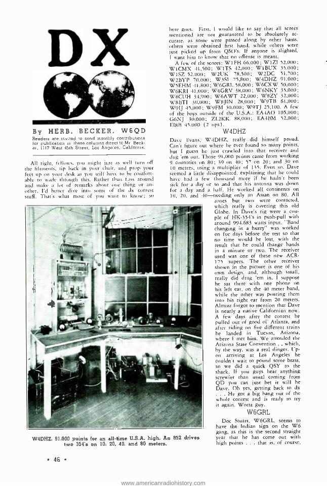
DX By HERB. BECKER, W6QD Readers are invited to send monthly contributions for publication in these columns direct to Mr. Beck- er, 1117 West 45th Street, Los Angeles, California.
All right, fellows, you might just as well turn off the filaments, tip hack in your chair, and prop your feet up on your desk as you will have to be comfort- able to wade through this. Rather than fuss around and make a lot of remarks about one thing or an- other. I'd better dive into some of the dx contest stuff. That's what most of you want to know: <o
here goes. First, I would like to say that all scores
mentioned are not guaranteed to be absolutely ac-
curate, as some were passed along by other hams. others were obtained first hand, while others were lust picked up from QSO's. If anyone is slighted, I want him to know that no offense is meant.
A few of the scores: W I FH 66,000; W I ZI 52,000; W1CMX 41.500; WITS 42,000; WIBUX 35.000; WISZ 52,000; W2UK 78,500; W2DC 51,700; W2BYP 70,000; W3SI 75,800; W4DHZ 91,000; WSEHM 41,800; W6GRL 58,000; W6CXW 50,000; W6KRI 41,000; W6GRV 38.000; W6NKY 35.000; W6CUH 34,900; W6AWT 22,000; W8ZY 32,000; WBBTI 30,000; W8JIN 28,000; W9TB 61,000; W91J 45,000; W9FM 30,000; W9TJ 25.100. A few of the boys outside of the U.S.A.: EA4AO 105,000; G6NJ 30,000; ZL2KK 88,000; EA4BM 52.000; EIRE 45.000 (2 ups).
W4DHZ Dave Evans. W4DHZ, really did himself proud. Can't figure out where he ever found so many points, but I guess he just crawled into that receiver and
dug 'em out. Those 91,000 points came from working 9 countries on 80; 39 on 40; 57 on 20; and 30 on
10 meters, using a multiplier of 135. Even so. Dave seemed a little disappointed, explaining that he could have had a few thousand more if he hadn't been
sick for a day or so and that his antenna was down for a day and a half. He worked all continents on
10, 20, and 40- needing only an Asian on 80. All zones but two were contacted, which really is covering this old
W4DHZ. 91.000 points for an all -time U.S.A. high. An 852 drives two 354's on 10. 20, 40, and 80 meters.
Qf;
Globe. In Dave's rig were a cou- ple of HK -354's in push -pull with around 994.683 watts input. "Band changing in a hurry" was worked on for days before the test so that no time would be lost, with the result that he could change bands in a minute or two. The receiver used was one of these new ACR- 175 supers. The other receiver shown in the picture is one of his own design, and, although small. really did drag 'em in. I suppose he sat there with one phone on his left ear, on the 40 meter band, while the other was pouring them into his right ear from 20 meters. Almost forgot to mention that Dave is nearly a native Californian now. A few days after the contest he pulled out of good of Atlanta, and after riding on five different trains he landed in Tucson, Arizona, where I met him. We attended the Arizona State Convention .. which. by the way, was a real dinger. Up- on arriving at Los Angeles he couldn't wait to pound some brass. so we did a quick QSY to the shack. If you guys hear anything screwier than usual coming from QD you can just bet it will be
Dave. Oh yes, getting back to dx . He got a big bang out of the
whole contest and is ready to try it again. Wotta guy.
W6GRL Doc Stuart, W6GRL, seems to
have the Indian sign on the W6 gang, as this is the second straight year that he has come out with high points ... that is. of course,
www.americanradiohistory.com

as far as the West Coast is concerned. This year Doc ran up 58,000 points, working 20 countries on 10 meters; 48 on 20; 33 on 40; and 2 on 80 meters. He still claims he can't hear 'em up there in Ventura. You see, he only has five V beam antennas (covering every point on the globe) and that probably explains why he can't hear anything. He, too, worked all six continents on all bands but the 3.5 mc. band. His transmitter is about the same as last year except that a few changes were made to facilitate quick QSY. In the final he is using four 852's in push -pull par- allel. This set -up allows Doc to use a full kw. when he grid modulates for fone on 10 meters. Yes, that's right ... fone! The receiver is the same old FBXA which has been worked over, and from the way he snags these dx birds, I guess it must be perking very well . although GRL with that R9, y.1.-fetching smile of his will modestly ( ?) say, "Can't hear a thing up there." Doc also said that if it hadn't been for the fact that he had to yank a few teeth a couple of days during the test, he would have run up a score.
W9TB W9TB wound up with a total of 61,000 points,
which is a sizable score in any language. Countries were 7 on 80 meters; 22 on 40; 55 on 20; and 22 on 10 meters. Multiplier came to 106. 6 WAC's were made and 2 FBTOC's. A funny thing happened while Ewald was QSO VK3MR: He received a re- port of 359 from the VK and thought that unusual. He began to investigate, and I guess that extra pull on his antenna rope had been just too much for the insulator, as his antenna was lying flat on the ground, hi. His rig consists of four 860's in push -pull par-
.A.
Dave Evans, W4DHZ (left) and Chas. Stuart, W6GRL (right) pose with W6QD while visiting
"Radio ".
allel, and works swell on 80- 40 -20, but not so hot on 10. His chief headache is VU2CQ, and he has plenty of company, too. W9TB is consolidating with W9DRN very soon, and then will have a separate rig on ten.
W2UK Tommy Thomas, W2UK, finished up with 78,500
points from 68 different countries worked on the 10,
W6GRL, high point station for the West Coast, uses four 852's which are grid modulated for 10 meter phone. The 60 watt Mazda lamp seen in the upper left of the photo is NOT
being used as a doublerl 58,000 points.
47
www.americanradiohistory.com

W6CXW, operated by Henry and Sam Sas- aki. They worked night and day to com- plete this new transmitter in time for the contest. It winds up with a 359 driving two
150 -T's. 50,000 points.
20, and 40 meter bands. The rig uses two 852's in p.p. with a kw. input. Grid bias modulation is used for fone. The receiver is a RME -69. Tommy agrees with hundreds of other hams that the 20 meter band is becoming a mess, what with the fones outside of the U.S.A. spreading all over the c.w. portion of the band. W2UK says he had a lot of fun even with all the boys tuning up their bugs during the best dx hours.
W6CXW Henry and Sam Sasaki, W6CXW, scored a total
of 50,000 points, which is mighty good for the West Coast. Year in and year out these fellows are the most consistent dx -ers I know. It is seldom they miss any of the choice dx that comes through. In this contest Henry won (or lost) the coin toss, and did the operating. It was OK with Sam as it gave him a chance to see more of his y.l. Henry worked his 112th country, and for Zones he has 39 . . . just one more to go. They have a new transmitter using two 150T's in the final stage, kicked by an HK -354. They had to step on it to get this new rig completed in time for the test, but they made it as the score will testify. The receiver is a Comet -Pro. For the antenna set -up a V beam is used, also a single -wire- fed Hertz. W6CXW was on all but the 80 and 160 meter bands.
Say gang, here is an account of the contest as ob- served from an East Coast station's standpoint. There
48
are several reasons why W8CRA wasn't in the test very much. One of them might have been the y.l. situation . but this time it was far from that, as the following narrative will bring out. Good of Frank was busy covering the test for the dx department of RADIO, and the following is taken word for word from his original penciled notes. Personally, I think it brings out the true spirit of a contest, and I can- not see where there was much left out. All of these notes were made during the progress of the dx test. All times mentioned are in e.s.t. Test started 7:01 p.m.
e THE 1936 INTERNATIONAL DX TEST
FROM START TO FINISH By FRANK LUCAS, W8CRA
6:45 p.m., Friday 13th, 1936 -W1SZ making a sked with U3QE for 7:01 p.m. -and the U petered out on the sked. U2NE asking when the test would start (as if he wouldn't soon find out). . . Logged at 6:50 -6:55 p.m.: VK3WW, U3QE, KA1 LB, LU6BJ, VU2BG, ZU5X, and ZT6K (you count the W's) all holding their prey till after 7:00.
7:01 p.m. -WOW! A 1400% increase in stations, key clicks, a.c. notes, tuning up, the groan of those powerful sixes -SU1SG and his steady stream of con - tacts-VQ8AB with that splattery, castor oil note,
W2UI{, 78,500 points, used a pair of 852's in the above transmitter.
www.americanradiohistory.com

and not knowing about the test -SPIDE best on 14 mc. SPIDT on 40. VS6AK with his terrific sock and punk receiver only making the fellows sore . . .
"YM4AA Danzig, with tears in my eyes "... XU3ST, XU8HW, XUIB, XUSAL, XU3DF, XU8AG mak- ing the East coasters scramble all at once (pardon, please, I got all six of 'em). J2LB, KAIDS, KA1ME, KA1AN whooping it up -U2NE batting away.
With those notes, why didn't the XU's keep their old prefix, "AC"? WI's, 2's, 3's making everyone look sick for the first couple of days ... YT7MT not doing so hot in the fone band. How was your average the first hour ? ? ? ?- EA8AO, EA8AF fighting it out side by side-CT! BY R9 on fone. Where was HC1FG this year ? -A W9 asking CM2DO for his QRK after receiving his number o.k. FM8D, old F3SMI in Martinique pounding away . . . A W8 giving ZB1C "101262 ", and with his T9 note did he get sore! Ask him. ZB1H slow but sure- VK6AF, J8CA, and XU1B CQ -ing by the hour with no re- plies . .. which goes to show that fellows don't look for dx in a dx contest -LA6A right in there -Again VS6AK's 599 sig giving out 339 -PK3BX best PK3 -GI5QX making a grand stand for his country- VU2CQ must have forgotten to turn on his receiver as usual (let's get together and buy him one). OM2RX doing plenty of justice to everyone -PK4DA best PK4 -EA4AO best EA and swell op. Ten meters just as hot as twenty and making some of the elusive dx easier to get -OK2AK best from "OK- land " - Looks like G6NJ in England this year- Thought all D4's were on the Rhine, but no, they were on the air (phew !). -D4ARR outstanding on three bands.
HJ3AJH holding Colombia; 0A4J, Peru -FA8BG doing great on 10 -And those cockeyed W fones would keep blasting away -That WI with those bad parasitics . and did ya hear those big W6's crawl out from under one another? Contest, a time when a CM is as worthy as a VS7 if you happen to need one. Of the PAO stations seems like an even break; none of 'em missed much -VK6FL best VK6 -VK7JB best VK7, and VK3JK topped all VK's for sock - W8CRA not raising a thing - W2UK going to town working the good stuff -J2HJ R9 plus- ZEUS coming through early in the morning. VS6AX and SM5SX raising plenty of commotion - XUIB best XU -VS6AH going after honors with snappy operat- ing and a fine sig ... FB8AB in a terrible spot and didn't hear him much - KA1ME working VK's -EI4G, never heard of him before -KA1AN boring through W fones on his frequency - ON4UU calling OM2RX on the opposite end of the band; wotta long shot that was -W6GRL hav- ing it over everyone on his fre- quency.
That W9 signing OP3X must have felt like two cents when caught. - VQ3FAR coming through at 9:00 a.m. How does WICMX spot so much good dx
[Continued on Next Pagel
Worm's eye view of W6GRL's five -way V -beam antenna system (photograph retouched to show detail). Each leg is 270 feet long and 70 feet high. Any adjacent pair may be fed from the
transmitter on any band.
Operating position at W4DHZ, showing the ACR -175 and the 7 tube home -constructed receiver which were both used in the contest.
49
www.americanradiohistory.com

-ZS2A after it again -ZS1AH with a swell sig - KA1LB coming through at 4:30 p.m., CQ -ing South America . . . how could he ? ? ?? U9AL creeping 30 degrees on the dial- U9AV's crystal was easy to copy -ZD8A quit after W3CHG told him the test was on, hi ... LU7EF another snappy QSO -CE4AD slow but sure -CT3AB best CT3 -OE6DK and OE3FL a tie with their sigs -OZ2M and OZ3FL fighting it out -G6QX working plenty of W6's and W7's ... FA8GK, wotta note -VP2TG always QSA -YL2FR only YL heard-LY1J having things his own way except for TDC ... NY2AB and his swell sending.... From the sound of their notes, some of the foreigners must have been using keyed diathermy machines for transmitters.
Did you notice around 4 p.m. every day how un- stable your receiver would get? So many fellows keying that it must have made the voltage fluctuate all over the country-the only "I" heard was I1IT- D4QET not so much in demand as when he was TS4SAX -HAF2D and HAF3D even with their sock. -'Twas better to be up in the band than on the edge -ES1C winding up a 24 ( ?) minute CQ- TF3AG heard just once.... W4EF keeping W4DHZ worried -F8OK, G6WN, PAOUN, D4GAD, OZ2M, G5QY, ZS1H, D4ARR, FA8BG, VK3YP, LU9AX, LU1EP and scores of others with their 10 meter wallops. -Where was ON4AU, G5BY, and J2GX ?- Digging down in the fourth layer for dx and finding W6QD, hi! -J2LB and J2ME out for it again. - There seemed to be no limit to the band's edge. Con- test must make them into "rubber bands ".
CP1AC came on in the middle of the week .
and say, did the gang haunt him? He didn't do much operating though. SU1RO is a little behind but going to town just the same -FA8BG and his clever operating; he must have a terrific score . . .
CM7AC coming right along -VP7NB operating a
little . VP7's always seem to be elusive as the deuce in a contest.... VP6YB and VP6MO battling away -EA1AB right in the thick of it along with EA4BM. Then ON4CRM in Belgian Congo playing with his key one afternoon. . . wonder why no CQ from him ? - ES7C not raising many . VO3HM getting oodles of answers. Ah! here's YR5AA . . .
(yes, I called him too). VS6AH came through one evening right through that QRM on the low fre- quency end of the band.
Those Canadian fones spoiling plenty of good dx -and those 'Koobans' didn't help things much eith- er. Boy oh boy, CX1CG and CX2AK out for hon- ors, with CX1CG holding the lead. F8TQ should have plenty of points. We won't forget XE1AM and his famous fist. .. . Morning and evening, VU2BG.
Did ya hear that wobbly creeping sig on the high frequency edge ... huh? Well, that char, my friends, was LX1AS and it took a solid hour to nurse him outta the mess . . . VP1MR, another multiplier - Counted 42 stations calling SUISG after one short CQ. K7ELM and K7PQ nailing them "1 -2 -3" .. .
Both real ops, PQ has the lead. After it's all over you won't hear a dx station on for months, I'll bet - OZ7Z and HAF2G always busy -LA3B and LA2B side by side burning it up. Looks like a split there.
VU2LJ didn't have his good xtal note; guess something blew up- 01' OH3NP must never sleep ... F8EO's sig will not be forgotten on all bands - VK3PG's 201 -A stepped right along with the best
50
FLASH W6KRI IF AC in 44 Minutes
On the morning of April 8th, W6KRI worked J5CE, ZT1Q, VK3VW, YV2AV, W5COU, ON4AU for W.A.C. in the remark- able time of 44 minutes. Two of these stations were on the same frequency and were worked at the same time.
of 'em.... Even W8KPB crawled off the edge. The 17th seems like a swell day for an EI QSO. They are all on, with EI8B putting all he has into his sig to keep ahead of EI9G and others. . . A W4 fone laying J8CA cold every morning, and wotta shame that is. The wallop of W8HWE's sig is really something to write home about. VS6AQ was just dx- ing -W4ZH laying for the choice stuff -KA1US taking things easy and smooth- SM7WS, another good SM QSO, and this fellow SM6SS all mixed up in that high frequency edge QRM.... OH6DH, a rare OH district, was plowing along, and get this one . . . here's W5BEE, a fone hound, on c.w.
How didja like copying that sig of CR7GD in all that QRM? EA7AV sounded like he gave his rig a shot of Fletcher's Castoria. . . . And where was that CT2 gang ? -CN8MQ taking his own sweet time. It's a miracle how FR8VX got by with two nice, long, juicy CQ's -and did you notice how the Euro- pean hams were QRMing GMR . Hi. Who said power was everything? Of all the D4 calls why did- n't one choose D4USA and save that troublesome "CQ- USA " ? -Someone was chopping SP1DE till he sounded like despite . hi. SU5NK for that third SU contact ... ZS4U doing OK for "ZS- land ",
Hear W3SI on almost any frequency- ZE1JE, weak but in there just the same. OK2OP must have plenty of trouble judging from those various notes - PK1MX's fone R9 calling a W2 and no soap from the W2 -VS6AG must have ditched his new bride for a few days 'cause heard him a lot... . CM2BC's band -spread note covering 30 degrees . . . LU1EP with a potent sig on 10. ZP2AC had no idea of what it was all about -and that bunch of K6's were sure piling up points. . CE1AQ still uses a 201 -A- J2KJ with great sock and J2CL coming through on 20 at 2:00 p.m. I1TKM opening up on Thursday - VQ3FAR having QRM from hyenas and asking for dope on numbers and rules, hi.
Thoughts after a nice long call . "Aw shucks! I used to work dx with this thing." The first prize should be a nice soft bed and a pint of ether. Naw, not that kind. Swell to wake up and find your an- tenna down due to heavy sleet, snow, and plenty of wind. This happened for five mornings. Western Pennsylvania hams had to go off the air from Wed- nesday on; no power. . . . Here it is Friday, March 20th and have heard 88 countries.... HH5PA stay- ing clear of numbers. . . VO1P running like clock work. HAF7A takes the "slow CQ" prize -Say, didn't that limit of 3 make you sore when 40 or so J's were coming through? Oh well, it's OK though, as a bunch of VO's showed up this year. Most of the VP9's and HP gang stayed on fone and didn't bother -Quite a few PY's on but didn't hear PY1AW.
[C'on:in/red on Page 'hl
www.americanradiohistory.com

. MS 4.* iSCC#000Yw n/r ` v..v I
cad... C i nut ,...,
. ¡awl
OH3NP, Hameenlinna, Finland
This station, which is owned and operated by Mr. E. W. Granqvist in Hameenlinna, Fin- land, is without a doubt one of the most pop- ular dx stations on the air today.
The radio activities of Mr. Granqvist date back some twelve years, when in 1924 he started by building broadcast sets. After considerable time had been spent along this line he ven- tured forth into the ham game. Toward the end of 1927 OH3NP finished his first ham receiver, a 2 tube Schnell. His first transmitter was completed early the next year, and in March 1928 he was ready for his first QSO. It seems as though 3NP had a great deal of difficulty raising many fellows with his little QRP rig. The transmitter at this time consisted of two Telefunken RE -134 receiving tubes using 120 volts on the plates at only 4 watts input. Being like all hams he wasn't satisfied; so re- building was next on the schedule.
By the summer of 1928 a new rig was ready to set the world on fire. Using the same tubes in parallel, Hartley circuit, and 240 volts on the plates, an input of 10 watts was obtained. With this setup all Europe was worked, togeth- er with Siberia, China, Algiers, and Egypt.
Then as Walle Granqvist says, "After several Hartleys were tried, I heard that the t.p.t.g. was a better circuit; so on April 3, 1929, I
started to build one up. It worked OK but all I could work were Europeans." In August 1929 Walk obtained two Philips TB 04/10 tubes, and then ... on September 17th with a chemical rectifier, 400 volts r.a.c. and 21 watts input, he hooked up with VTVVZ in Quetta, India, for his first QSO with the new rig. Then in close order came PK2AJ and ZLIAS, the latter being a difficult country for Finland.
Always showing progress, it was now time to build a new receiver. At the end of 1930 a t.r.f. job with detector and audio was in use. It was really a fine receiver and without a doubt was all that a ham could want. In Walle's own words, "January 1931 I started to build my first crystal -controlled transmitter using four stases, hut when it was finished I
could get no crystal, hi. At last in September I received the crystal and could get on the air." This rig consisted of a c.o. TB- 04/10, f.d. TB04 /10, f.d. RV -218, and a p.a. RV -258. The last two tubes were Telefunken a.f. type.
[Continued on Page 7.1
51
www.americanradiohistory.com

The
For the c.w. op- erator working in the 14, 28, and 56 m.c. bands and living where auto ignition, dial tel- ephone clicks, and other types of noise render reception nearly impossible, the receiver described herein is a real step towards eliminat- ing the noise. There is nothing "new" about this receiver; it uses a combination of good
t rafflc Ten, t X Inhaler DeLuxe By LLOYD M. JONES, W6DOB
No fancy frills, no "doo dads ", every component justified from a performance standpoint, this superhet may be constructed with but a few simple tools at a fraction of the cost of a manufac- tured receiver giving comparable results. It may be duplicated from scratch" for $50 including cabinet and power supply,
less if you have any kind of a "junk box ".
Front Panel Layout of Controls
systems which have been published many times heretofore. The set was built for the ultimate in performance on the above mentioned bands. Rather than single dial control, band switching coils, etc., two -dial tuning and plug -in coils are used. Both glass and metal tubes are used, the glass type for economy, and the metal type for desirable characteristics not obtainable in the glass line. Three of these sets have been built, with not the slightest trouble encountered in making them work. In each case, upon com- pletion of wiring and tuning on the set, signals were heard, and a few minutes in aligning the set finished the job.
Construction of Cabinet The chassis and cabinet and shield partitions
were made at home with the aid of square, hammer, scribe, tin snips, a few blocks of 1" x 2" pine, four 4" C clamps, and an old piece of plate iron for an anvil. 20 gauge body steel
was used throughout. The finished chassis is
17" x 10" x 21/2" outside dimensions, and is
bent in the same manner as the cabinet. The
* 547 West 106th St., Los Angeles.
52
cabinet was made by bending o n e
piece of 40"x10 "
to fit around the _hassis, which al- lows a back bend
of 11 /2" at each end. At the top of each corner bend, it is necessary to cut out a
piece (90 degrees) to allow a smooth joint when bent into position. To make a smooth corner, it will help if a no. 36 drill is used to drill a hole at the apex of the angle before it is
cut out. Using a little care with one's measure- ments, and with all scribe marks on the inside of the cabinet- to -be, it is only a
few minutes' work to bend the chassis and cabinet and lid- mounting. This is done by placing the strips of 1" x 2" pine on each side of the work and on line with the scribe work, clamping them securely with the C clamps. Care should be taken to keep the clamps clear of the band. Use a hammer or mallet and pro- ceed to bend the material slowly from one end to the other, taking precaution not to make too large a bend at any one point, as this would leave waves due to stretching. The rear piece used to fasten the hinge and top lid is 2" x 16" and bent so that one inch will be at the rear and one inch on top, leaving an opening 14" x
51/2 " in the rear for ventilation. The lid is 81/2" x 16". The miscellaneous controls are used to fasten the cabinet to the chassis in front, and 6,/32 bolts are used at all other points. The hinge for the lid may be purchased from a
hardware store and should be 15" long. The two shields for the r.f. and translator stages are 3" x 5" , and 5" high. The oscillator shield is
5" x 5 ", and 5" high. The crystal shield can is
2" x 5 ", and 3" high. All shields are mounted by spade bolts, which are riveted thereto with the same size rivets as those used in fastening the wafer sockets to the chassis. The power transformer hole was cut with a cold chisel, and socket holes cut with a circle cutter, which may be obtained at your radio or hardware store for about $1.75 if you do not already have one. After cutting the various pieces, lay each piece on the flat anvil and hammer out all kinks, etc. Do not worry about hammer marks, as the paint covers them. The crackle paint used is pre- pared by NaAld, obtainable at most radio stores.
www.americanradiohistory.com

606 6C6 6 661 6L? 76
\ 110V 3A rust
C-0.25 µf d. 200 volt C1-35 µµEd. C2 -75 µµEd. midget C3-75 µµ1d. midget C1- Rebuilt midget;
one rotor, two stator
C. -, -Same C,; -Same C7-30 mad. trimmer C -SO µµíd. fixed
mica C -See text C111 -100 lipid. fixed
mica C11 -75 µµEd. b.o.
trimmer C
1 -25 µfd. 25 volt electrolytic
:-.1;7 -(Part of b.o.unit) C11-100 µµfd. fixed
mica
ASEND,Rf CIRCOITS DUD BKW, WEAR B0. C-CW.STRONC B0.
The General Wiring Diagram Unmarked condensers
are .01 !Ad. R1 -1000 ohms, 1 watt R2- 25,000 ohm wire -
wound potentio- meter
R3- 25,000 ohms, IO watts
R4 -5,000 ohms, 1 watt R:,- Approx. 60,000
ohms (see text) R71-100,000 ohms, 1
watt R7-360 ohms. 1 watt R,..- 100,000 ohms, 1
watt R.1 -360 ohms, 1 watt RI- 10,000 ohm wire -
wound potentio- meter
R11- 100,000 ohms, I
watt
It is merely brushed on smoothly, according to instructions on the can, and put in the gas range oven set at about 100 degrees F. After thirty minutes, have a look to make sure that all is well, and if it looks "well done ", remove the set to a convenient place for a day or so of drying. Take care that the oven does not get too hot while baking, lest it make the finish dull instead of bright. Paint any or all parts you wish except the under side of the chassis, which would hinder soldering the grounds. So much for the chassis and cabinet.
The Circuit At the higher frequencies it is quite necessary
to use regeneration in the r.f. stage in order
R1 25,000 ohms, 10 watts
R0- 25,000 ohms. 10 watts
R14-50,000 ohms, 1
watt R, ; -360 ohms, 1 watt Rila- 100,000 ohms, 1
watt RIT- 100,000 ohms, 1
watt R16 -5,000 ohm wire -
wound potentio- meter
R 14- 50,000 ohms, 1
watt R211 -5,000 ohms. 1
watt R_ I- Approx. 70.000
ohms (see text) R2.2-50,000 ohms, 1
watt
4 ^26
R23-5.000 ohms, 1
watt R21- 50,000 ohms, 1 ..
watt R25- 100,000 ohms, 1
watt R26-50,000 ohms, 1
watt R27 -(Part of b.o.unit) R28- -1,000 ohms, 1
watt RFCI -21/2 mh. pie
wound choke RFC. -16 mh. shield-
ed r.f. choke RFC11 -10 mh. shield-
ed r.f. choke SWITCH -2 gang, 4
point IFT1 -Air -tuned i.f.t.,
465 kc. IFT, -Same for diode IFTso -465 kc. beat
ose. coil
to realize any gain, and since the signal -to- noise ratio of the set itself is more or less de- termined by the first stage, it is desirable to have a variable front panel control of the re- generation. This takes the place of the r.f. cathode control used in many sets, and should not be considered an added control. The r.f. translator coils are wound on forms marked on a screw -cutting lathe (belonging to a friend) and then notched deep enough to hold the wire with a three -cornered file. The lathe tends to chip the forms if the actual notching is tried with it. The r.f. translator coils are made as high L/C as possible for the maximum amount of voltage gain, and tuned with 75 .q.tfd. con- densers across only enough turns to effect cov-
53
www.americanradiohistory.com

I10V
0 0
POWER
0 453
tvl ANT. GND
RF
0
fie
PHONE JACK
T
IFT
VSWITCH 'IC' HAWN'S
JlCl2
e 6 K 7 I F T 0
m
6J7
0 6L7 IFT 0
6H6 0'
NOISE IFT,
606
osC LII
C4
Chassis Layout, Top View, Drawn to Scale
erage of the bands used. The oscillator coil is
wound on a small, four prong form, and uses high C for extreme stability. Oscillator har- monics of 7 mc. are used for the 28 and 14 mc. bands, and the harmonic of 14 mc. for 56 mc. The use of a harmonic reduces the tendency towards "pulling'. of the oscillator- translator circuits. There is plenty of output from the oscillator and one need only worry about stabil- ity and mechanical rigidity of the oscillator. Hence two -dial tuning, and no worry about making the front end track nor a compromise in L/C ratios of the r.f. translator and oscil- lator as in the case of single dial tuning. Single dial control is also somewhat impractical with r.f. regeneration. Three -winding coils are used in the r.f. translator. The tuned circuit, C, -L acts as an antenna trimmer, and at the same time tracks the two coils, L2 and L5, (over small limits), by compensating for the r.f. 6D6 plate and plate lead capacity to ground of L4. In other words, L, reflects the same load to L2
as L4 does to Ls, assuming that L2 and L;, are of the same inductive values, and ignoring the small loading effects that L3 and L8 might have. C, is mounted through the chassis between the r.f. tube and coil, and is adjusted by means of
a screw driver. A slot is cut in the end of the condenser shaft with a hacksaw. The r.f. cath-
ode tap is adjusted so that the r.f. stage will start to oscillate (antenna connected) when
54
BO 0 0
117- SUB CHASSIS SHIELD
about 70 to 90 volts is applied to the r.f. screen grid through R2. The padding condenser, C5, is of 150 gltfd. and is used to spot the band on the tuning dial so that complete coverage of a band may be obtained. It is well to adjust this padding condenser by listening to your own crystal oscillator, or some commercial who might serve as a "marker" station, so that ac curate logging of stations may be had for future use. Inductive coupling from the oscillator to the translator is used so that the proper voltage input may be had on each band, and is coupled through the winding, L4, at the base of the coil which corresponds to the antenna winding, L3i
on the r.f. coil. The number of turns of Ls is determined only by experiment, as will be described in the adjustment of the set. Fixed bias is used on the translator in order to main- tain a fixed value for maximum conversion of average signals. The crystal filter in this re- ceiver was made from a standard, air -tuned Hammarlund i.f. transformer by removing the primary winding, L7, and condenser from the can, and putting mica washers on each side of the primary winding to form two winding slots, each one about the same width as the winding, L7. Eighty turns of no. 30 d.s.c. were wound in the same direction in each slot, and the out- side of one winding, L8i and the inside of the other winding, L9, connected to ground. L8 is
used for the crystal voltage, and L9 for the
www.americanradiohistory.com

Bottom View. Showing Sub -chassis Layout of Parts and Method of Mounting
Top V ew of the Receiver. Note the Simplicity and Newness of Layout
www.americanradiohistory.com

CUT OUT y ,. --CUT OUT -, DRILL HOLE DRILL HOLE
fig-- 10` - -- -- 17 .... IO' -- --12
t. 18"
CABINET
a N
'2 2
b
17
1
I
b
G
--16 k'-
CHASSIS BEND LIP5 ON o.n, 90' DOWN BEND o.n, 90' DOWN. BEND Jo b. 90' DOWN
-16"
LID
REND
o
SHIELD MATERIAL
2 --5" x 13" (r.l. transformers)
1 -5" x 16" (oscillator)
1 -3" x 15" (xtal shield can)
1 -2" x 5" (top for xtal can)
1 -2" x 15" (noise circuit can)
1 -2" x 10" (power supply shield)
All 20 gauge body steel
N
16'
BACK STRIP FOR HINGE
phasing, or neutralizing voltage. This unit, LT,
L9, LR, and tuning condenser, mounts in one end of the home -made crystal shield -can, with a hole in the chassis to permit screw driver ad- justment of the LT tuning condenser. The crystal itself was mounted by means of a five - prong wafer socket directly above. The remain- ing portion of the can is used to mount the three -plate Cardwell phasing condenser, CR, insulated from the shield can to reduce capacity to ground of the stator as well as the rotor. The shorting switch is made by soldering a small piece of spring brass to the end of the rotor shaft and fastening a second contact on a small 1/2" standoff insulator, the switch being closed when CS is set at minimum capacity. The out- put from the junction of the phasing condenser and crystal is fed through a 50 1.11afd. condenser, C7, to the low impedance winding, L10, which consists of another 80 turns of no. 30 d.s.c. wire, wound directly over the original secondary winding, L17, of the i.f. transformer, and the inside lead grounded. L10, L11, and condenser are mounted in the top of the Hammarlund shield can. Isolating the primary and secondary windings in separate shield can allows for bet - 'er elimination of images while using the crvs- al. When the crystal is not in use the low
.rnpedance windings, LR and L10, (an imped- .nce of approximately 10,000 ohms as com-
56
T
pared to 100,000 ohms, more or less, of a reso- nant circuit) merely act as a link- coupled cir- cuit and no gain is lost. The purpose of the low- impedance windings is to provide better impedance match to the crystal, which has roughly 10,000 ohms impedance at 465 kc. This circuit is probably the most efficient and selective of any crystal filter circuit in use.
The new noise suppressor system* used in the receiver does much towards helping many types of interference, especially the "spark" type. Although the two do not go hand in hand without special modifications of the silencer circuit, it is possible to use either the crystal or noise suppressor in this set and go through almost any kind of noise and copy that dx station that is only R2 or R3. In a few cases when using the crystal, it is possible to help reduce the noise by using the noise sup- pressor as connected here. The noise suppres- sor i.f.t. is a small Hammarlund for diodes with the two windings jammed close together by cutting the cardboard form from between the two windings with a razor blade and inserting a wooden dowel for support. The unit is mounted underneath the chassis with the open end facing between the 6J7 and 6H6 sockets. Note the shield between the 6J7 and 6H6 tubes
*Lamb adaptation of the Scott -Taggart system, various modifications currently shown in QST.
www.americanradiohistory.com

Lt Lz
14 mc. 16 t. 8 t. no. 14
no. 26 cath. tap
28 mc. 8 t. 4 t. no. 14
no. 26 cath. tap / t.
56 mc. 2 t. 2 t. no. 14
no. 26 cath. tap / t.
L3
COIL DATA
L4 L5 L6 L,2
10 t. 8 t. 16 t. 7 t. 13 t. no. 26 no. 26 no. 14 no. 26 no. 16
cath. tap 51/2 t.
6 t. 4 t. 8 t. 12 t. same coil no. 26 no. 26 no. 14 no. 26
2 t. 2 t. 2 t. 5 t. 3 t. no. 26 no. 26 no. 14 no. 26 no. 16
cath. tap
TAP FOR TUNING CONDENSERS C^-, C3
14 mc., 41/2 turns; 28 mc., 11/2 turns; 56 mc., / turn. (All taps are counted from ground end.)
11/3 t.
and the regular i.f. circuits. This is quite necessary for maximum noise suppression and isolation of the two separate circuits on the same frequency, which otherwise might cause regeneration and instability. The second de- tector uses fixed bias with grid injection of b.f.o. voltage by means of two pieces of hookup wire twisted together for about one inch, the exact amount to be determined by measure- ments or a listening test, to be described later. Referring to the photo, the left dial tunes the r.f. translator, while the right dial tunes the oscillator. The controls on the bottom row, from left to right respectively, are as follows: r.f. regeneration control ; i.f. volume control; send, b.f.o. on, b.f.o. off; noise suppressor con- trol ; b.f.o. vernier adjustment. The a.c. switch is controlled by the r.f. regeneration control. The small dial directly under the second detec- tor cathode meter is the crystal phasing and off /on control, which couples to the phasing condenser by means of a small bakelite shaft between the translator -oscillator shields. The meter is there merely because it was in the way laying in the junk box. The power supply is simple and as long as one does not use any power tubes it is entirely adequate, since there is no detectable hum in the earphones. Power tubes are unnecessary, since the second detector output is more than ample for comfortable earphone use. One side of the heater trans- former is grounded. One heater lug of each tube socket is soldered to the chassis for sim- plicity in wiring, and eliminates the need of
heater by -pass condensers. The suppressor grid lugs are also soldered to the chassis. Plenty of tie -points are used for simplicity and neatness of wiring. Note that the power transformer and 80 tube are placed at the rear left of the chassis and the h.f. oscillator at the front right, for heat isolation, which helps reduce the os- cillator drift. The placement of other parts was chosen for short leads and convenience.
Adjustments Once the set is ready for adjustment the reg-
ular routine of aligning the i.f. and crystal units may be followed. Detailed information has been published many times so need not be gone over here. However, too much emphasis can- not be placed on the fact that one should actually follow the instructions in order to ob- tain best crystal filter performance. It is not uncommon to find operators who have failed to learn how to use their filter or realize the great benefits it offers. The writer has actually found operators who would cut in their crystal and even though the noise would drop consid- erably in relation to the signal, the signal also dropped. Examination would show that the beat oscillator was off tune or the set not prop- erly aligned and the operator, not knowing what a real filter sounded like, would condemn the filter as "n.g." The only practical and sure way to align a crystal filter is to remove the crystal from the receiver, and set it up as an external crystal oscillator. Roughly align the i.f. circuits to the crystal oscillator. Then as a
final touch -up, couple a small amount of its
57
www.americanradiohistory.com

output to the grid of the translator and adjust all the i.f. trimmers for maximum second de- tector cathode current. By means of the i.f. volume control, keep the second detector cath- ode current adjusted to about .5 to .8 ma. (If the i.f. volume control is too far advanced, the second detector cathode current might be as high as 5 ma., which would probably ruin a 0 -1 ma. meter.) Even this method is not ex- act since a crystal used as a parallel resonator may be a few hundred cycles different than when used as a series resonator. However, it will be found that the selectivity of the i.f. transformers is broad enough to allow for this difference. At any rate, the signal should not drop when the crystal is used as compared with the signal without the crystal. As an example, in the set described, with the crystal off. a steady incoming carrier may be adjusted to read 0.7 ma. at resonance, and with the crystal on. the same signal will actually read 0.9 ma. second detector plate current. Of course with the selectivity of the crystal the background drops very noticeably, and at first one would suspect the actual signal of doubling its vol- ume even though it may have actually dropped slightly.
Set the noise control on the off position (maximum resistance). Adjust the second de- tector 76 cathode current to 0.2 ma. (no signal nor b.f.o. input). With the b.f.o. on, adjust twisted wire coupling, C9i to 0.21 ma. cathode current, or more if you desire a loud beat (of course other values will hold for different types of tubes) . For each set of coils the translator tube should be adjusted to 0.2 ma. (no signal nor oscillator input). Then determine the proper number of turns on the translator coil to increase the cathode current to 0.6 ma., only after you have tuned in a signal for maximum signal strength by adjustment of the r.f. trans- lator tuning dial, which is to say that the r.f. translator is tuned to the incoming signal and the oscillator is either higher or lower by the amount of the i.f. used. The nearer you tune the r.f. translator to the oscillator frequency the greater will be the reading of the translator cathode current, or visa versa. The antenna trimmer adjustment, C1, will be easy to find by listening to an incoming signal and adjust- ing it for maximum response, with the same dial settings as those used while adjusting the translator cathode current as just described.
After the set is working properly as a straight superhet and with crystal in the off position, start your car, buzzer, or other device which
58
will produce a spark -gap type of noise (electric shaver used here). Then advance the noise control (decreasing cathode resistance in the 6J7/6H6 circuit) and tune the noise i.f.t. trim- mers for minimum noise. The exact setting of both trimmer condensers of the i.f.t. is critical for maximum suppression.
Operation As stated earlier in this article, the receiver's
signal /noise ratio is usually determined by the first stage. Therefore, one should try to run the r.f. regeneration close to the oscillating point, where there occurs an enormous amount of amplification. The i.f. volume should be set to comfortable output. When bad noise (auto, dial phones, etc.,) is present, a little experimenting will be needed to find the opti- mum setting of the i.f. and noise controls for maximum noise suppression. This setting is by no means critical. The noise suppressor control should have no effect upon the incom- ing signal other than to stop the noise until a point is reached ( "threshold ") where the in- coming signal or set noise blocks the receiver. After using the set for a few days, the operator will become accustomed to the various controls and will find it no more difficult to operate than any other type of receiver.
Results As for results on weak signals, the writer
has QSO'ed Europeans and Africans on 14 and 28 mc. when they were R2, QSA 5 at a time when backing off on the noise control would have literally knocked the phones off one's head, from some model T warming up while its master ate breakfast. Then again, some Europeans and Africans have been logged as an honest R9 (the second detector cathode meter is a 0 -5 ma. one and they made the needle hit the pin). The noise /signal ratio was such that the needle would return to 0.4 ma. when they stopped sending. EA4AO, F8EO, F8CT, EA8AF, FA8BG, SP1DE, and OK2IC are some of the more consistent "pin bangers ". On 56 mc. of course, the set will not hold the s.e.o. modulated "wobbulators ". It makes them sound like a fingernail drawn briskly across about one inch of window screen. On the other hand, extremely steady signals of the T9X type are readily received with as much ease as on 28 or 14 mc. Harmonics of 28 and 14 mc. stations from all W districts have been copied on 56 mc.
A small hole drilled at the end of a crack in sheet steel will stop it from growing longer.
www.americanradiohistory.com

Flood
Because of the utter impossibility of naming every amateur worthy of mention in connection with the recent floods, we have taken one part of the country as "typical" of what transpired in hundreds of cities throughout the east and are giving an account of the part amateur radio played in that community. Thousands of other amateurs whose calls are not mentioned here did just as fine work and deserve equal credit: both space limitations and the fact that many have hidden their lights under a bushel make it impossible to describe their work or even to list them. We turned on the spotlight to give amateurs in other parts of the country a picture of what took place in badly flooded territory: the spotlight just happened to fall on Neu, Hampshire. from which one of the most con- nected and coherent accounts was received through the courtes) of IY'1CME.
In the worst disaster in the history of the State of New Hampshire, amateur radio played a most important part. With wire services disrupted in all directions and the capital city of Concord virtually isolated from the rest of the state, the Governor called upon New Hamp- shire amateur to coöperate for the benefit of the State's citizens. Although complete details will never be known because of the reticence of some of the amateurs who took part, such material as is available furnishes a brilliant rec- ord. Beginning with the Governor's call on a Wednesday night, the amateurs stuck to their posts -many with battery powered rigs until wire communication was restored the following Monday. A summary of the activities of the principal stations follows:
The Governor called W 1 BFT in Concord for radio communication to as many New Hamp- shire points as possible. W1BFT called QRRNH on 3750 and was answered by W1TA in Nash- ua, W1ANS in Milford, and W1IP, W1FFL, and W1CME in Manchester. He then called WI APK in Pembroke by land phone and asked him to get the New Hampshire 75 meter phone stations lined up for a tie -in with the 80 meter c.w. net.
In the meantime, W1AVJ installed a re- ceiver in the Governor's office in Concord and, with the help of relief operators, maintained continuous watch on 3755 kilocycles, this fre- quency being adopted as the New Hampshire State frequency.
After the failure of electric power, W1JJD's push -pull 45 rig was revamped to use 10's with
Activity B battery supply, and, with a receiver that was converted to battery operation, resumed traffic. W 1BFT and W1AVJ were in almost continu- ous operation for four days.
Assisted by W 1I JB, W 1 APK worked both phone and c.w. with his high power phone rig until the power failed. Then the oscillator was used with battery power and the station thus kept on the air. This station is credited with saving a life by taking a message relayed by wigwag across the Merrimac river and relaying it to Concord, where an ambulance was dis- patched in response to the message.
W1IOC in Boscawen ran a police line and at the risk of his life waded across a half -sub- merged bridge to secure materials for an emergency transmitter, which he constructed by the light of a candle. The transmitter he built supplied the only communication to four towns for several days.
In Manchester, the Merrimac and Piscati- quoag rivers divided the city into three sec- tions, each isolated from the other until amateur radio got on the job. W1EFE set up a 5 meter outfit in the steeple of a church and worked all sections of the city, providing the only contact for the section in which he was located. Five meter equipment was set up at all American Legion Posts and the State Armory. The A.R.R.S. stations on 3709 handled a large amount of urgent Red Cross traffic.
At the Amoskeg dam, W1HFO and W1HJM manned 5 meter equipment for direction of the C.C.C. boys who were sandbagging the dam and power station to prevent their being swept away.
W1BII and W1FTJ handled many rush mes- sages for the telephone company and in that way helped speed the restoration of telephone service.
W1CME handled 1326 messages and over 11,000 words of press in 83 hours on the air.
In Nashua, W1BCT and W1GEY handled traffic on 160 and 75 meters as long as the power held out. Then they dismantled their rigs and took them to a tire shop where diesel electric power was available. Hurriedly string- ing an antenna, they got on the air again and maintained 24 hour watches for several days.
Credit should also go to the s.w.l.'s who were tuned to the 75 meter phone band and de- livered many messages that were broadcast to
(Cnnriniea on Page '8]
59
www.americanradiohistory.com
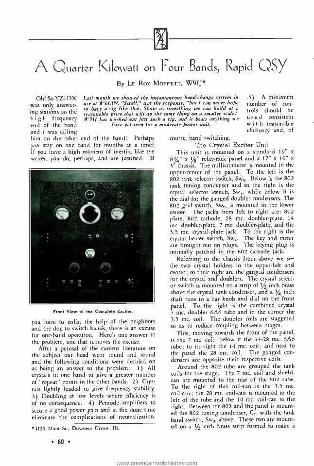
?4.1
A Quarter Kilowatt on Four Band, Rapid QSY
Oh! So YZ1DX was only answer- ing stations on the high frequency end of the band and / was calling him on the other end of the band! Perhaps you stay on one band for months at a time? If you have a high moment of inertia, like the writer, you do, perhaps, and are justified. If
By LE ROY MOFFETT, W9IJ*
Last month we showed the instantaneous band -change system in use at W6CIN. "Swell," was the response, "but I can never hope to have a rig like that. Show us something we can build at a reasonable price that will do the same thing on a smaller scale." W91J has worked out just such a rig, and it beats anything we
have yet seen for a moderate power unit.
Front View of the Complete Exciter.
you have to enlist the help of the neighbors and the dog to switch bands, there is an excuse for one -band operation. Here's one answer to the problem, one that removes the excuse.
After a perusal of the current literature on the subject our head went round and round and the following conditions were decided on as being an answer to the problem: 1) All crystals in one band to give a greater number of "repeat" points in the other bands. 2) Crys-
tals lightly loaded to give frequency stability. 3) Doubling at low levels where efficiency is
of no consequence. 4) Pentode amplifiers to
secure a good power gain and at the same time eliminate the complications of neutralization.
*4125 Main St., Downers Grove, III.
60
.5) A minimum number of con- trols should be used consistent with reasonable efficiency and, of
course, band switching. The Crystal Exciter Unit
This unit is mounted on a standard 19" x
83/4" x 1/8" relay -rack panel and a 17" x 10" x
3" chassis. The milliammeter is mounted in the upper- center of the panel. To the left is the 802 tank selector switch, Sw3. Below is the 802 tank tuning condenser and to the right is the crystal selector switch, Sw while below it is
the dial for the ganged doubler condensers. The 802 grid switch, Sw2, is mounted in the lower center. The jacks from left to right are: 802 plate, 802 cathode, 28 mc. doubler -plate, 14 mc. doubler -plate, 7 mc. doubler -plate, and the 3.5 mc. crystal -plate jack. To the right is the crystal heater switch, Sw4. The key and meter are brought out on plugs. The keying plug is
normally patched in the 802 cathode jack. Referring to the chassis from above we see
the two crystal holders in the upper -left and center; to their right are the ganged condensers for the crystal and doublers. The crystal select- or switch is mounted on a strip of 1/2 inch brass above the crystal tank condenser, and a 1/4 inch shaft runs to a bar knob and dial on the front panel. To the right is the combined crystal 7 mc. doubler 6A6 tube and in the corner the 3.5 mc. coil. The doubler coils are staggered so as to reduce coupling between stages.
First, moving towards the front of the panel, is the 7 mc. coil; below it the 14 -28 mc. 6A6 tube; to its right the 14 mc. coil; and next to the panel the 28 mc. coil. The ganged con- densers are opposite their respective coils.
Around the 802 tube are grouped the tank coils for the stage. The 7 mc. coil and shield - can are mounted to the rear of the 802 tube. To the right of this coil -can is the 3.5 mc. coil -can; the 28 mc. coil -can is mounted to the left of the tube and the 14 mc. coil -can to the right. Between the 802 and the panel is mount- ed the 802 tuning condenser, C,, with the tank band switch, Sw3, above. These two are mount- ed on a 1/2 inch brass strip formed to make a
www.americanradiohistory.com

bracket so as to mount to the chassis. The screw that holds this bracket is used for the common ground return for the 802 stage, and all by- pass condensers and r.f. ground returns are brought to it under the chassis. The plate block- ing condenser, CY0i and RFC,0 are mounted by their leads directly to the condenser and switch assembly. The output coupling condenser, C8, is mounted to the rear of the 28 mc. coil on a small mounting bracket and stand -off insulator. This allows a short lead to the grid of the 803 stage, when the 803 unit is mounted above this unit.
Referring to the wiring in the chassis, we have R C,,, 112, C9, C,0, R3, R4, C18, R5,
C12 and Rs mounted on a bakelite strip. This assembly is mounted by means of screws to the chassis below the ganged tuning con- densers. Most of the wiring on this strip can be done before mounting in the chassis. Com- mon grounding points are used for each 6A6 tube.
The crystal holders are rather massive in order to give them a large thermal capacity (in order to cut down frequency drift) . They have been used at W9IJ for over two years and have proven satisfactory. Each is 31/4" x 3" x 1" and was machined from brass stock and one face lapped. Four one -inch holes were cut in a piece of 3/16 -inch bakelite to form a holder for the crystals. This piece is screwed to the brass base. In the picture of the top view of this unit the construction is shown. The dust covers
The Low Power Unit. Note the Special Crystal Holders.
can be removed easily to allow changing of the crystals. The dust cover is cut the size of the brass block from 3/16 -inch bakelite. Small phosphor bronze "fingers" were cut to hold the top plates against the crystals and make elec- trical contact to them. The "fingers" were
Side View of the 803 Stage. Note the Tube Shield.
mounted by screwing them to tapped holes in the bakelite holder. Leads are soldered to the "fingers ", which can be seen protruding from the holder. A hole was cut in one of the brass holders and a heater resistor inserted. This is enough to drift an X cut crystal plate from about 7004 to 7000 kc. or to get you out of a bad QRM spot. Retuning of the crystal tank condenser will also give a small order of fre- quency control. A socket for additional crys- tals has been provided between the 3.5 and 14 mc. coils.
The four -ganged crystal and doubler con- densers are mounted individually by brackets to the chassis. Care should be used in lining the condensers up in order to get a free -running gang unit. Flexible couplings are used between the condensers. They will be found especially convenient when the doublers are being adjust- ed for maximum output. The tracking of the ganged unit is secured by approximately halv- ing the capacity and inductance of the circuit each time the frequency is doubled. The con- densers and inductances used give tracking over the amateur bands close enough for practical purposes.
The plate coils for the 802 stages are mount- ed in shield cans having a diameter of 2.5 inches and a length of 33/4 inches. The 3.5 and 7 mc. coils are supported by the midget tank trimmer condensers mounted and ground-
61
www.americanradiohistory.com

. TO TIP -TO SLEEVE
110 V. ACi
R1 -5000 ohms, l watt. 82-250 ohms, 2 watts. R,3- 20,000 o h m s. 1
watt. R4- 12,000 o h m s, 1
watt. R5-1.000 o h m s, 3
watts. R11- 12,000 o h m s, 1
watt. R7- 12,000 o h m s, 1
watt. R5-500 ohms, 10
watts. 11,r -4,003 o h m s, 50
1IF63 V. 6RIELD
TO KEYING RELAY bcG[j)
watts, semi -var- iable.
Ris- 15,000 ohms, 25 watts, semi -var- iable.
R11 -1,500 ohm flat card type resistor.
C1 -100 µpfd. midget air condenser.
C2-50 µpfd. midget air condenser.
C; -25 µpfd. midget air condenser.
C1 -15 µpfd. midget air condenser.
+B TO OSCILLATO
TB TO BUFFER STAGE
The Crystal Exciter Unit C5-75 µpfd. midget
air condenser. C1 -50 µpfd. midget
air condenser. C7 -35 µpfd. midget
air condenser. C5-75 µpfd. midget
air condenser. C1 -.01 µfd. mica. C10 -.01 pfd. mica. C11 -.01 pfd. mica. Cl5-.01 pfd. mica. C13-.001 pfd. mica. C14 -.001 pfd. mica. C15 -.0005 pfd. mica.
ed to the top of the coil shield can. The 14 and 28 mc. coils are supported by small stand- off insulators in the cans. The ground return leads from these two stages are brought out through the chassis and run to the common ground point for this stage. The plate leads are brought out through small rubber grom- mets near the top of the cans.
The 802 tube shield was so cut that the shield extended up to a point level with the bottom of the internal tube shield. Extensive use has been made of by -pass condensers and r.f. chokes to isolate the circuits and keep the r.f. where it belongs. Some of the r.f. isolating and by -pass condensers can be dispensed with, perhaps, without harmful results, but C2 was found to clear up the original trouble encoun- tered with feedback. It was found that feed- back was present when the milliammeter plug was patched into the doubler jacks. It will be noted that the milliammetter is mounted near the r.f. plate leads of the 802. This coupling from the plate to the milliammeter and leads back into the plate circuit of the doublers, via the meter cord, couples into the grid circuit of the 802, and is a source of feedback. The
62
C56 -.001 pfd. mica. C17 -.01 pfd. mica. C15 -.01 pfd. mica. 0111 -.0002 pfd. mica. C2II -.002 pfd. mica,
5,000 volt. C_1 -.01 ufd. mica. C -.01 pfd. mica. C53 --.001 pfd. mica. C24 -.01 pfd. mica. C_ .01 pfd. mica. C21, .001 pfd. mica. C27 -25 µpfd. midget
air condenser. ji -t, -Short jacks.
o
MA-0-100 ma., 2% inches in diam- eter.
Sw1- Rotary tap switch, 10 point, single circuit.
Sw5- 3- Rotary tap switches, 4 point, single circuit.
Sw4- Toggle switch. RFC1-111- Midget pie -
wound r.f. chokes. T1-6.3 volts, 2.5
a m p s., filament transformer.
milliammeter leads should be shielded and the shielding grounded and the meter by- passed to ground to clear this source of trouble.
The voltage on the doublers should be set to 300 volts. This will require about 900 ohms on R5 from the plus end for a 400 volt supply, and about twice this for a 500 volt supply. The 802 screen -grid and crystal -plate tap is adjust- ed for 235 volts. This will require about 1400 ohms on RA from the doubler voltage tap. The suppressor voltage is adjusted for 35 volts under operating conditions. This will require approximately 3000 ohms from the cathode tap on R50.
The unit is lined up at the highest fre- quency to be used, in this case 28 mc. The small trimming condenser mounted on the 14 mc. coil, should be set near maximum capacity. The crystal and each succeeding doubler stage tank condenser should be adjusted to resonance as denoted by minimum plate current. The out- put of the 802 stage may be checked with a
10 or 15 watt lamp or the d.c. grid current of
the following stage. About 50 ptifd. of the out- put coupling condenser, C8, is used on all bands, but it may be necessary to reduce this to about
www.americanradiohistory.com
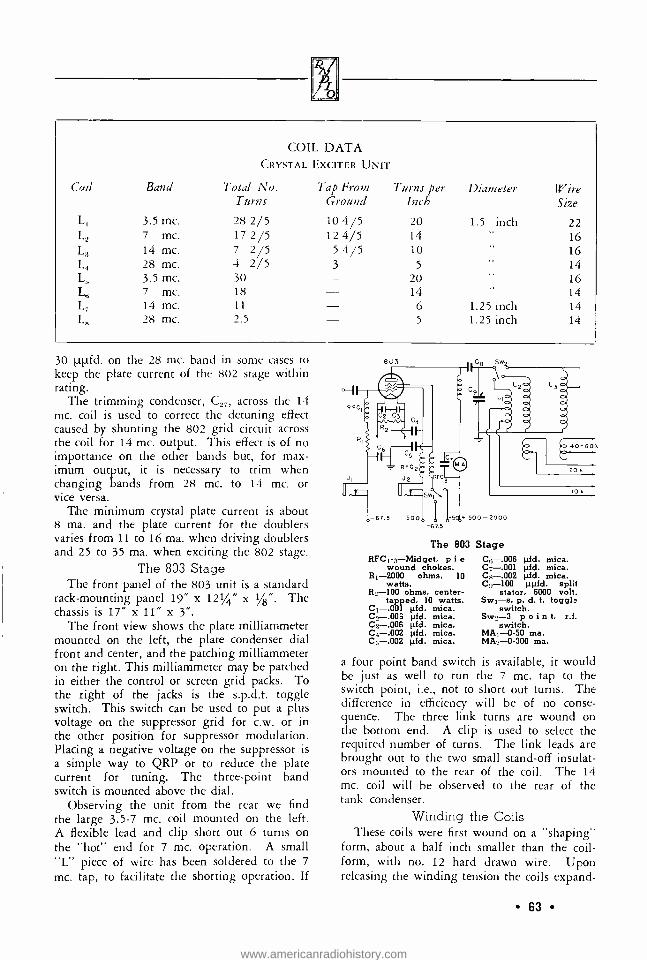
COIL DATA CRYSTAL EXCITER UNIT
Coil Band Total No. Turns
Tap From Ground
Turns per Inch
Diameter Wire Size
L, 3.5 mc. 28 2/5 10 4/5 20 1.5 inch 22 L2 7 mc. 17 2/5 12 4/5 14 16 L; 14 mc. 7 2/5 5 4/5 10 16 L} 28 mc. 4 2/5 3 5 14 L, 3.5 mc. 30 20 16 L,; 7 mc. 18 14 14 L_ 14 mc. 11 6 1.25 inch 14 L, 28 mc. 2.5 5 1.25 inch 14
30 1.tt..tfd. on the 28 mc. band in some cases to keep the plate current of the 802 stage within rating.
The trimming condenser, C27, across the 14 mc. coil is used to correct the detuning effect caused by shunting the 802 grid circuit across the coil for 14 mc. output. This effect is of no importance on the other bands but, for max - imum output, it is necessary to trim when changing bands from 28 mc. to 14 mc. or vice versa.
The minimum crystal plate current is about 8 ma. and the plate current for the doublers varies from 11 to 16 ma. when driving doublers and 25 to 35 ma. when exciting the 802 stage.
The 803 Stage The front panel of the 803 unit is a standard
rack -mounting panel 19" x 1214" x 1 /8 ". The chassis is 17" x 11" x 3 ".
The front view shows the plate milliammeter mounted on the left, the plate condenser dial front and center, and the patching milliammeter on the right. This milliammeter may be patched in either the control or screen grid packs. To the right of the jacks is the s.p.d.t. toggle switch. This switch can be used to put a plus voltage on the suppressor grid for c.w. or in the other position for suppressor modulation. Placing a negative voltage on the suppressor is a simple way to QRP or to reduce the plate current for tuning. The three -point band switch is mounted above the dial.
Observing the unit from the rear we find the large 3.5 -7 mc. coil mounted on the left. A flexible lead and clip short out 6 turns on the "hot" end for 7 mc. operation. A small "L" piece of wire has been soldered to the 7
mc. tap, to facilitate the shorting operation. If
The 803
RFC1 -3- Midget, p i e wound chokes.
R1 -2000 ohms, 10 watts.
R2-100 ohms, center - tapped, 10 watts.
C1 -.001 pfd. mica. C2 --.006 pfd. mica. C3 -.006 pfd. mica. C4 -.002 pfd. mica. C5- -.002 pfd. mica.
Stage Ce -.006 pfd. mica. C7 --.001 pfd. mica. C8 -.002 pfd. mica. C9-100 ppfd. split
stator, 6000 volt. Swi-s. p. d. t. toggla
switch. Sw2-3 p o i n t, r.f.
switch. MA1 -0 -50 ma. MA -0 -300 ma.
a four point band switch is available, it would be just as well to run the 7 mc. tap to the switch point, i.e., not to short out turns. The difference in efficiency will be of no conse- quence. The three link turns are wound on the bottom end. A clip is used to select the required number of turns. The link leads are brought out to the two small stand -off insulat- ors mounted to the rear of the coil. The 14 mc. coil will be observed to the rear of the tank condenser.
Winding the Coils These coils were first wound on a "shaping"
form, about a half inch smaller than the coil - form, with no. 12 hard drawn wire. Upon releasing the winding tension the coils expand-
63
www.americanradiohistory.com

ed to the correct size. They were then threaded on the coil- forms.
The tank condenser control is extended to the front panel by means of an isolantite flex- ible coupling and a piece of 1/4 inch bakelite rod.
Bottom View of the 6A6 -802 Unit.
The band switch is supported by means of a
1/2 inch brass strip to the "hot" stator plates of the condenser. This strip also is used as a
connection to the switch arm. A flexible cou- pling and piece of 1/4 inch bakelite rod is used to extend the switch control to the front panel. The switch rod is brought through a bushing to the front panel. The plate blocking condenser is supported by a no. 10 wire lead to the "hot" stator plates. The 28 mc. coil is supported at one end by the "ground" stator plates and the other end of the coil is soldered to the 28 mc. switch point. This will allow very short leads. Output coupling is obtained by clipping across the required number of turns on the ground end of the coil.
An attempt was made to use the 14 mc. coil for 28 mc. operation but due to the high tube capacity and length of the connecting leads it was found that only one turn could be used on the coil on 28 mc. This was not consistent with our personal idea of a tank coil. Our ex- perience with 28 mc. is that this band is a
problem unto itself and proper consideration should be given to circuit design if reasonable efficiencies and proper operation are to be ex-
pected. The r.f. choke is supported by the plate meter
terminal, and an r.f. by -pass condenser is mount- ed directly across the meter terminals. The shield around the base of the tube was made by cutting the top from a coil -shield can hav- ing a diameter of three inches.
64
X The view of the under side of the chassis is
self -explanatory. It should be noted that all leads are shielded and that the shielding is grounded. All the by -pass condensers from tube to ground are grounded at a common point. The grid blocking condenser is support- ed by the wiring to the socket and the other end to a stand -off insulator, which is the input terminal.
The extensive shielding of the leads and the isolating of circuits in this stage has paid the expected dividends. No trace of coupling be- tween the grid and plate circuits, via the wiring or otherwise, is noticeable.
Screen and plus suppressor voltages for this stage are obtained from a potentiometer. A rath- er heavy bleeder current is recommended to give good voltage regulation if a lower pow- ered stage, as the 802 stage, is keyed. A 40,000 ohm, 200 watt, semi -variable resistor is sug- gested for a 1600 volt supply and a 50,000 ohm resistor for higher voltage supplies. The taps are adjusted to give 500 volts on the screen and 50 volts on the suppressor for "key - down" conditions. The negative voltages for the control grid and for the suppressor are obtained from a common bank of small bias batteries.
The coil values have been so chosen that almost the full value of the tank condenser is used on 3.5 mc., a little less than half scale on
COIL DATA 803 STAGE
Li - 3.5 - 7 mc., 14 turns for 3.5 mc., 6 turns shorted out for 7 mc., 3 turn link wound on ground end of coil. Wound 6 turns per inch, diam- eter 4 inches, no. 12 wire.
L2 - 14 mc., 5 turns wound 3.5 turns per inch on 2.5 inch form of no. 12 wire, 3 turn link.
Ls - 28 mc., 3.5 turns wound 3 turns per inch, diameter 1.5 inches, no. 8 wire. Coil extended 3/4 turn from ground end to give a balanced pick -up for the output line.
7 mc., quarter scale on 14 mc., and about one - fifth scale on 28 mc.
The 803 stage is used to drive a 1 kw. final amplifier at W9IJ. As might be expected, this unit will "kick" the final in the most approved W6CUH manner. However, from 100 to 150 watts has been found to be plenty of driving power for this final. For exciting the 1 kw,
www.americanradiohistory.com

stage, two or three turns are used on the pick- up coils and one turn on the grid tank link. The balanced grid tank of this stage is switched similar to the 803 stage.
The 803 unit can be link coupled to the an- tenna feeders via any of the standard tuning units, such as the Collins low -pass filter or the regular "zepp." tuning arrangement. If a non -resonant transmission line (one properly terminated in its surge impedance) is used to feed the antenna, it can, of course, be fed from the pick -up turns on the amplifier.
No trouble was had in getting the full rated output from the stage. If trouble is exper- ienced with getting the stage to take the load properly, the d.c. voltages should be checked on the grids, especially the screen grid.
A few suggestions, perhaps, will not be amiss. It is not advisable to allow even mom- entary overload on a tube as expensive as the 803; it is better to buy more or bigger tubes and run them within the manufacturer's ratings. If two tubes are used it would be better to op- erate them in push -pull, if frequencies as high as 14 or 28 mc. are to be used, due to the high inherent tube capacity of this type of tube.
In practice it will be found that the adjust- ments of the crystal -exciter unit are not at all critical. About half of either the 14 or 28 mc. band can be covered at W9IJ, without appreci- able loss of efficiency, by merely retuning the
Side View of 6A6 -802 Unit, Showing Coil Arrangement.
grid tank of the 1 kw. final amplifier, the plate tank, and the antenna tuning. From exper- ience it has been found that when the frequency change is much greater than this, it is advisable to retune the stages, unless a considerable drop in efficiency and output power can be tolerated.
We wish to thank Mr. Conklin, W9FM, for the photos of the "rig ".
Bottom View of the 803 Unit.
In conclusion we can only say that the units have lived up to expectations and that we feel repaid for our efforts. They can be duplicated by following this article with but a fraction of the effort expended in the "cut and try" part alone on the original model.
REPLACING VOLUME CONTROLS Reviewing the experiences of thousands of
service men in handling volume control replace- ments, George Mucher of Clarostat offers the following "don'ts":
Don't attempt to replace C -bias and antenna C -bias controls before checking:
1. Control tubes for "shorts ". 2. Bleeder resistor (if used). 3. Whether original control has a built -in bias
resistor. In such cases use external bias re- sistor if exact duplicate control is not avail- able.
Don't attempt to replace screen grid control before checking:
1. Control tubes for "shorts ". 2. Screen by -pass condensers for "shorts ".
Don't attempt to replace plate circuit tone controls before checking series condensers for "shorts ". Due to high a.c. voltages generated across control on loud signals, we strongly rec- ommend the use of wire -wound controls for such applications.
Failure to heed the foregoing "dont's" may result in burned -out controls.
Don't cut shaft and solder lead wires before checking control action. Failure to observe this precaution is sufficient cause for dealer to re- fuse replacement.
Don't attempt to replace with other than rec- ommended tapers.
65
www.americanradiohistory.com
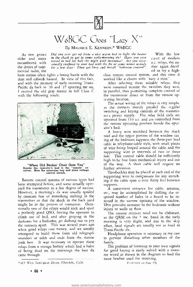
As one grows older and more encumbered with the duties of com- mercial radio, the ham station often fights a losing battle with the dust and cobweb hazard. In view of this fact, and with the memory of early morning Trans - Pacific dx back in '26 and '27 spurring me on, I excited the old gray matter to full Class C with the following result.
W6BGC Goes "Lazy X" By MAURICE E. KENNEDY,* W6BGC
Did you ever get up from a nice warm bed to light the heater in the shack to get in some early- morning dx? Have you ever tossed in bed for half the night with insomnia? Are you occa- sionally confined to your bed with the flu or some minor malady for a few days? Then get busy and install "bedroom control ".
"When Old Rockin' Chair Gets You" Beside the operator's bed is the "remote" re- ceiver. Note the extension key and plate voltage
control switch.
Remote control systems of various types had been attempted before, and some actually oper- ated the transmitter to a fair degree of success. However, a morning's dx was usually spoiled by constant fear of something melting in the transmitter or that the shack in the back yard might be in the process of cremation. Occa- sionally one of the relays would stick and spoil a perfectly good QSO, forcing the operator to climb out of bed, and after groping in the darkness for a bathrobe, go dashing out to pry the contacts apart. This was several years ago when good relays cost money, and we usually
attempted to build them from old telegraph sounders or odds and ends from the station junk box. It was necessary to operate these relays from a storage battery which had a habit of being dead on the mornings the best dx came through.
t'415 West Lexington Drive, Glendale, Calif.
66
With the low cost of modern a.c. relays, the au- thor again decid- ed to try a high -
class remote control system, and this time it worked like a charm with "nary a miss ".
After selecting three suitable relays, they were mounted nearest the switches they were to parallel, thus permitting complete control of the transmitter direct or from the remote op- erating location.
The actual wiring of the relays is very simple, as the contacts merely parallel the regular switching and keying controls of the transmit- ter's power supply. The relay field coils are operated from 110 a.c. and are controlled from the remote operating position beside the oper- ator's bed.
A heavy wire stretched between the shack roof and the upper portion of the window cas- ing of the bedroom supports the three -pair lead cable in telephone -cable style, with small pieces of wire being looped around the cable and the supporting wire at intervals of two or three feet. This control cable should be sufficiently high to be free from mechanical injury and out of the way. A short cable will require no further attention.
Turnbuckles may be placed at each end of the supporting wire to compensate for any stretch- ing if the cable span is over thirty feet between supports.
A convenient entrance for cable, antenna, etc., may be accomplished by drilling the re- quired number of holes in a board to be in- serted in the narrow opening of the window. This provides entrance to the bedroom without injury to walls or floor.
The remote receiver need not be elaborate, as the QRM on the 7 mc. band in the early morning is very slight, and due to the skip effect, local signals are usually not as loud as
Trans -Pacific dx. Headphone operation is necessary in my case
to prevent disturbing other members of the family.
The problem of listening to your own signals for good keying is easily solved with a moni- tor wired as shown in the diagram to feed the same headset used for receiving.
[Continued on Page 83]
www.americanradiohistory.com

TURF. PAM CARTE
o,5rAN`:,. ^y.M..a. z.
-10 .,. p ,
u
BED ROOM
}' y s AM/ .,,...
Wiring of the Remote Control Relay System
Showing a Corner of the Shack: 40 Meter Transmitter and Direct Operating Position.
67
www.americanradiohistory.com

Ef{lcizney Modulation in Simple Terms By J. N. A. HAWKINS, W6AAR
The whole subject of efficiency modulation seems to be rather hazy in the mind of the av- erage phone man. The advantages of class BC operation over the older class B system of ef- ficiency modulation are becoming more widely appreciated. Several new ideas are presented herewith, and although ordinary linear amplifi- cation will probably be succeeded by the new expanding linear amplifier described in this is- sue, a thorough understanding of the principles of grid modulation is essential in order to get the idea behind the new expanding amplifier. Inasmuch as this article was prepared several months ago it includes nothing on dynamic shift amplification, and perhaps a general qual- ification should be made to the effect that the statements made in this article apply only to steady -state or constant -axis amplifiers and the limits of efficiency and output do not apply to dynamic shift or expanding amplifiers.
"Grid Modulation" All low -level modulation systems can well
be classified under the general heading of grid modulation. Suppressor grid modulation of a
pentode is obviously grid modulation as is the system known as grid bias modulation. The op- eration of a radio frequency amplifier as a class B or BC linear amplifier also is a form of grid modulation. Perhaps it best could be termed grid excitation modulation. As far as the op- eration of the amplifier tube is concerned there is practically no difference between grid bias modulation and grid excitation modulation. In the grid bias modulated amplifier the grid ex- citation is held constant while the d.c. bias voltage is varied by the audio signal. See figure 2. In grid excitation modulation, or linear r.f. amplification, the d.c. grid bias is held constant and the amplitude of the grid excitation is var- ied by the audio signal. See figure 3. The re- sult, as far as the amplifier grid and plate cir- cuits are concerned, is the same in either case.
There is very little difference in cost, linear- ity, or adjustment between grid bias and grid excitation modulation, but what difference there is seems to favor grid excitation modulation, or the linear amplifier system, at the present time.
Amplitude Modulation Amplitude modulation of any wave involves
a variation in the peak amplitude of the carrier wave so that the envelope of the resultant mod-
68
ulated wave is similar to the waveform of the audio, or modulating, signal. When a carrier wave is completely modulated (100% modulat- ed) the unmodulated amplitude of the wave is alternately doubled and then reduced to zero. The amplitude of a wave corresponds to the r.f.
RF IN yPUT
Bt
RF OUTPUT
EXACTLY NOT CRITICAL BUT CUT OFF ABOUT CUTOFF CB NOT OVER .002 UFOS
Figure 1
Class BC linear amplifier. The cathode bypass resistors must not be over .002 ¡Ad.
voltage across the antenna that is radiating the wave. Thus when the amplitude of the carrier wave is doubled the r.f. voltage across the trans- mitting antenna is also doubled. As an antenna is effectively a pure resistance, doubling the voltage across it also doubles the current flow- ing through it (by Ohm's law) . When the volt- age and current in any resistive circuit both double, the power in that circuit has quadrupled. Thus complete modulation of a carrier wave causes the instantaneous power in the antenna (or output circuit) to vary between the limits of zero power and four times the normal un- modulated carrier power. Note the word instan- taneous; it must be carefully distinguished from effective power. By integrating out the instan- taneous variations in carrier power caused by 100% modulation it is found that the effec- tive power (averaged over one audio, or mod- ulating cycle) has been increased exactly 50% over the power in the unmodulated carrier. A 50% increase in average power output equals a 22% increase in effective antenna current. (Note that for the purposes of this discussion pure, sine -wave modulation is assumed.)
It is this 50% increase in average carrier power that is supplied by the output of the audio modulators in a plate -modulated phone transmitter. In a high level modulation system this is done by increasing the plate input to the class C modulated amplifier 50 %, which in-
www.americanradiohistory.com

creases the r.f. output in the same degree due to the fact that the conversion, or plate effi- ciency, of a class C stage is relatively independ- ent of plate input, when operating properly. Thus the audio modulators in a plate- modulat- ed transmitter are really modulating the plate power supply of the class C stage, and not the class C stage itself. Thus plate modulation is often called power modulation.
Grid, or Efficiency Modulation It is a fundamental of grid modulation that
the average plate input (as indicated on a d.c. plate meter) to the modulated amplifier must not vary during modulation. Thus if the av- erage plate input remains constant and inde- pendent of modulation, the 50% increase in average power output of the modulated ampli- fier which occurs during complete sine -wave modulation can only be obtained by increasing the average plate efficiency of the grid mod- ulated amplifier 50%. Thus all grid modulation systems are efficiency modulation systems. The average plate input to the modulated amplifier remains constant, but the efficiency of conver- sion of that input into r.f. power output is var- ied at an audio frequency rate by the modulating voltage applied to the grid bias supply in grid bias modulation, or to the preceding amplifier in grid excitation modulation.
So far the grid modulated amplifier has been analyzed only from the standpoint of average variations in plate efficiency and power output that occur during modulation. The instanta- neous power output of the grid modulated am- plifier must swing up to four times the unmod- ulated carrier, then down to zero power, then back to the unmodulated value, during periods of 100% modulation. This quadrupling of in- stantaneous power output results from two sep- arate causes. First, the instantaneous plate ef- ficiency varies, during complete modulation, from the normal unmodulated value up to twice normal, then down to zero efficiency and then back to normal.
The variation in plate efficiency accounts only for a doubling in instantaneous power output during complete modulation. The rest of the increase in the power output comes from the fact that the instantaneous plate current is also varying at an audio frequency rate between the limits of twice normal and zero current. As the plate voltage is constant the instantaneous plate power input varies exactly with the plate cur- rent so that doubling the instantaneous current doubles the instantaneous power input. The
Instead of presenting a table showing oper- ating constants for all tube types and at all possible plate voltages (which would be awk- ward), the following formulae may be used to derive all the unknown constants for class BC operation from the factors that are generally known in advance, such as maximum allowable plate dissipation, of the tube to be used, and available plate voltage. From these factors may be determined the unknown factors such as d.c. battery bias, resistance of the cathode bias resistor, optimum d.c. plate current, and carrier power output.
Unknown Factors: WIN = d.c. plate input power, in watts. WOUT - r.f. unmodulated carrier power,
in watts. IP = average d.c. plate current, in am-
peres. ECei = negative battery bias equal to the-
oretical cut -off, in volts (1/2 total bias). RK = cathode bias resistance, in ohms.
Known Factors: Ea = d.c. plate supply voltage, in volts. WPL - rated plate loss, in watts. = amplification factor of tube used.
Formulae: W = 1.66 WPL WOUT = .66 WPL
1.66 WPL (1 + i)
- Et EB
EB
1+i1 EB2 l.l
1.66WPL (1+p)2
' nstantaneous plate current varies directly with the instantaneous plate efficiency and when both have been doubled (during 100% modulation) the r.f. power output has been quadrupled. It should be noted that the variation in plate cur- rent between zero and twice normal occurs at an audio frequency rate, not a syllabic rate, and thus good voltage regulation in the plate power supply is not necessary. When the plate cur- rent drops to zero, energy is stored in the last filter condenser. When the plate current dou- bles, this stored energy is given up again and as the plate voltage is constant, this variation in
69
www.americanradiohistory.com

Z - G QRENT IA
á - \y GJ - P yP
á 7- P ? 06-L" u_cPO
,11
ú OJPP \0 ¡:
0 W Q Nm
RESULTANT AUDIO BIAS MODULATION
i
GRID -' VOLTAGE
ENVELOPE OF R.F. EXCITATION
AUDIO MODULATING VOLTAGE
DEGENERATIVE FEEDBACK VOLTAGE
Figure 2
Class BC bias modulation (no audio bypass on cathode resistor). Note the two forces working on the grid bias voltage: the audio modulation voltage and the degenerative feedback voltage, working in opposite directions. The degree of degenerative feedback is dependent on the value
of unbypassed resistance in the cathode circuit.
Q
FF-- \G JpRENT SEP9 G
ñ _ P ÉQP O U GtJ0,6
e, `p G ,P -----i- - dlo rt.
Gp ú<-; Nó .
T- T
GRID 3 VOLTAGE
INSTANTANEOUS AXIS (SUM OF BIAS AND DEGENERATIVE FEgEOBACK VOLTAGES)
ENVELOPE OF R.F. EXCITATION
Figure 3
Class BC linear or excitation modulation. Here there is only one force working on the bias: the a.f. variation in current through the unbypassed cathode resistor (degenerative feedback). Contrary to widespread belief, there is no "modulation gain" in a class BC linear amplifier. This
should be apparent from study of the above curves.
70
www.americanradiohistory.com

VI
Ñá
`JyqENT
.1D`,tr
P
/I p T-
GRIP VOLTAGE
Conventional Class B Linear
ENVELOPE OFR F. EXCITATION
Figure 4
Amplifier Curves, Shown for Comparison.
plate current causes no variation in the average power drawn from the plate power supply, al- though the instantaneous plate input alternately doubles and drops to zero. This explains how the instantaneous power output of a 200 watt grid modulated amplifier can swing up to 800 watts on the instantaneous (audio) peaks al- though the average d.c. plate input is only 500 watts. It must be noted that the last filter condenser in the plate supply hum filter should be large enough to take care of the audio fre- quencies that pass through it.
In pure class B operation of a linear amplifier the bias is made equal to theoretical cut -off, or d.c. plate voltage divided by the p of the tube used in the amplifier. The plate current is not actually cut -off when a tube is biased to this point, as no practical vacuum tube has a con- stant lx clear out to the cut -off point. However, only a small amount of plate current flows at theoretical, or projected, cut -off and for most purposes it can be assumed that actual and theoretical cut -off coincide.
In the class BC amplifier fixed bias equal to cut -off is used, and in addition, there is a cath- ode bias resistor used which supplies additional bias. The additional bias supplied by the cathode bias resistor is not critical and can be
almost anything from half cut -off to several times cut -off. However, the best compromise value for the medium Ea
tubes (pi between 8
and 16) seems to be about cut -off. Thus the total bias (fixed plus cathode) should equal about twice cut -off. The fixed bias should be well bypassed to audio frequencies and the bias source should have good voltage regulation, particularly if the amplifier is to be driven hard into the positive grid region. The fixed bias is
rather critical for minimum amplitude distor- tion, and once set it should be left alone. If it
is desired to experiment with bias, vary the cathode bias but leave the fixed bias alone once it has been set for a given plate voltage. There is one very important thing about the cathode bias that must not be overlooked. The cathode bias resistor must not be bypassed for the audio frequencies. A radio frequency bypass across the resistor may be used but it should not be over .002 ltfds. Placing an audio bypass across the cathode resistor short circuits the degener- ative audio feedback voltage which appears across the cathode resistor. This degenerative feedback voltage is what keeps the amplifier lin- ear even though the average total bias exceeds cut -off. This feedback voltage varies directly with the plate current. It alternately adds to
71
www.americanradiohistory.com

and subtracts from the bias voltage. On the modulation peaks, when the instantaneous plate current is twice its average value the instantan- eous cathode bias doubles, and when the plate current drops to zero a half cycle later, the cathode bias also drops to zero. This is shown in figures 2 and 3. Thus if a given amplifier uses cathode bias equal to cut -off (total bias twice cut -off) the total instantaneous bias swings from its normal unmodulated value of twice cut -off up to three times cut -off, then down to cut -off, then back to twice cut -off dur- ing each audio cycle of complete modulation.
It should be noted that the degenerative feed- back voltage (audio) which appears across the cathode bias resistor is deducted from the plate voltage and thus also appears as a degenerative voltage in the plate circuit. The effect of this voltage can usually be neglected in practical applications and calculations, except where very low 11 tubes are used in the amplifier. In other words, to simplify calculation the actual plate voltage on the tube (supply voltage minus in- stantaneous value of voltage across the cathode resistor) may be assumed as constant under modulation, though it is not strictly so.
The use of degenerative feedback in the class BC amplifier allows high peak and unmodulat- ed plate efficiency to be obtained and even im- proves the linearity of the amplifier over the conventional class B amplifier. The power gain through the class BC amplifier is somewhat less than through a comparable class B amplifier but the reduction in overall power gain is slight and the increase in output, efficiency and linear- ity is well worth the slight loss in gain.
It should be mentioned that there is no mod- ulation gain through a class BC linear amplifier. No matter what the total unmodulated bias may be, if the fixed bias is equal to cut -off, the preceding stage must be completely mod- ulated if the class BC amplifier output is to be completely modulated.
Due to the fact that the d.c. grid current flows through the cathode bias resistor of a class BC amplifier it is desirable to keep both the cathode bias resistance and the d.c. grid current low in order to avoid audio distortion arising from changes in bias with grid current flow. To keep this distortion low it is desira- able, therefore, to use a tube with the highest possible transconductance, as cathode bias re- sistance and d.c. grid current both vary inverse- ly with the transconductance of the tube used.
As the instantaneous peak plate efficiency must be able to double in order for the ampli-
72
fier to have 100% modulation capability, the unmodulated plate efficiency must be adjusted to not more than one half of the maximum attainable peak plate efficiency.
The theoretical maximum peak efficiency of a class B amplifier (one biased to cut -off) is 79%, as the angle of plate current flow remains constant at 180 °. Thus one half of this peak value equals 39 %. Practical class B amplifiers rarely exceed about 66% peak efficiency, and 50 to 60% peak plate efficiency is more com- mon in practice. Thus the unmodulated plate efficiency of a practical class B amplifier ranges from about 25 %to 33%.
The class BC amplifier can have almost any desired angle of plate current flow between 180° and 0° merely by increasing the degener- ative cathode bias. Therefore, like a class C amplifier the theoretical maximum peak plate efficiency is 100 %.
For reasons of driver and power supply cost the peak plate efficiency is usually held at about 80%, which allows a maximum unmodulated plate efficiency of half this value, or about 40 %. With average tubes of medium la (between 8 and 16) this requires a total bias equal to be- tween two and two and a half times cut -off.
The variations in plate efficiency and plate current that must occur during modulation are caused by superimposing the audio frequency modulating voltage on the d.c. grid bias volt- age, or on the r.f. excitation voltage. See figures 2 and 3. As the grid must be allowed to swing somewhat positive (with respect to the filament) at least during modulation, it will intercept electrons from the filament, causing d.c. grid current to flow. If the power output is to be free from distortion this flow of grid current must not be allowed to change the negative bias on the tube. This necessitates a very low resistance d.c. grid return to ground.
The r.f. driver is best stabilized by connect- ing a tungsten filament lamp across either part of the driver plate tank or else across the low impedance coupling link which transfers energy from the driver plate tank to the grid tank of the modulated amplifier. Of course, a re- sistor of any convenient value up to about 5000 ohms could be used in place of the tungsten filament lamp, but the lamp is usually more convenient as well as self -adjusting due to the temperature- resistance characteristic of a tung- sten filament.
W1CAV has been using the same S -tube rectifiers in his transmitter since 1923!
www.americanradiohistory.com

2214 HAMS (,mot BE WRONG!
WHOLESALE R!DIO 5R'/ICE CO, INC
MGM 1.0.SYLVAHI4 KE1.IN.
On February 3, 1936, an event took place that had the hams in and around New York talking in their sleep. It was a ham fest held in New Yorks' famed Hotel Pennsylvania, originated and sponsored by Wholesale Radio Service Company.
Sure we expected a crowd. We figured we had lots of friends and the program looked mighty interesting. But we didn't expect the crowd that jammed the hall to capacity. They filled every available seat; packed the aisles and, if it had been an old fashioned hotel, they probably would have perched on the rafters! And what a talk
RADIO EQUIRMENT
...,_,, jtJHUtt4lt RAow kRIKE (6
1!1!
fest it was! After the speakers got through we talked about everything near and dear to the heart of a ham. Some of us are still hoarse from try- ing to shout louder than five or six other fellows sitting near by who had exactly the same idea. We're sorry - really sorry - that all of you fellows
WHOLESALE RADIO SERVICE (O<
CHICAGO. ILL. NEWYORK.N.Y. ATLANTA. GA. 901w.JACUONìLVD.R too SIXTH AVE.N430WPEACHTREEIT-NW
7ROHX.W.Y. NEWARK .N.1. NE ETO/WHAM AD 219 CENTPALA
couldn't be there. Maybe some day we'll build a hall in the exact center of the U.S.A. that can seat forty or fifty thousand hams; install some P.A. equipment (we have lots of it around, you know) and dare you fellows to do your worst. Anyway, we feel pretty cocky about the swell turn -out. It was nice to see all the hams come out in full force, and they didn't come for free eats. They came because they knew and liked Wholesale Radio Service Company. They've known us for years. Most of them are our cus- tomers. They know we sell anything and everything for the ham (careful shopping hn-3 taught them that our prices are LOW) and they know that Wholesale's service is the fastest, most reliable in the radio game. Most impor- tant, they get what they want when they want it, because we handle all of the nationally known lines. Oh yes, before we forget, 99% of the hams have our 68 page exclusive Ham Catalog. If you haven't a copy, be sure to write for catalog No. 60 to- day -it's FREE!
WHOLESALE RADIO SERVICE CO., Inc , Dept R 56 901 W. Jackson Blvd. Chicago, Illinois
Rush a Free copy of your exclusive Ham Catalog No. 60.
Name
Address
Town State
73
www.americanradiohistory.com

TYPE MT100.GD
Net Price $4.80 *
NO FINER CONDENSER
,h,,,, c >.,, <.,,, MIDWAY
Month after month, year after year, the sale of Cardwell Mid- way Condensers proves the need for the MIDWAY Series. Every Cardwell Condenser patent and years of mechanical experience and engineering skill combine to produce the finest variable con- denser offered to the American amateur. The quality is the high- est. The price is well within the Amateur's budget.
TYPE MAX. CAP.
NUMBER MIN. CAP.
OF PLATES
DEPTH BrHIND PANEL
NET PRICE TO AMATEUR
MR-I05-BS 105 10 II 29/." $1.60 MR-260-BS 260 13 25 39/1." 1.70
MT- 50-GS 50 11 I I 29/1fi" 2.10 MT-100-GS 100 15 21 3'/ ,;"" 2.65
DOUBLE CONDENSERS MR-100-BD 100* 10* II 39/,: 2.75 MR-260-BD 260* 13* 25 41/2" 3.00 MT- 35-GD 35* 9* 7 3/9tft" 3.30 MT- 50-GD 50* 1 1 * I I 3/9,6" 3.50
.Caps ,ty of each serticn.
TheAllenD.Cardwell Mg.Corp. 15 Prospect Street, Brooklyn, New York
74
Expanding Linear Amplifier [Continued from Page 14]
When using those tubes that should not be operated with more th..rt rated plate loss at any time, there is no point in using more than 20% axis shift. With 20% axis shift the plate loss is the same resting or completely modulated. The increase in plate input during modulation (25% increase) is approximately equal to the increase in r.f. output from the amplifier caused by the presence of sidebands.
The following table shows typical conditions for a single 211 tube operating with 100% modulation, resting with 20% axis shift and resting with 33% axis shift.
EXPANDING CLASS BC OPERATION TYPE 211
100 Watts of Carrier Output 12
Max. plate loss 100 watts Max. plate current 150 ma.
Completely Resting Resting Modulated 20 5, shift 33% shift
Modulation capability Plate efficiency (ay.) Plate input power
Carrier output Sideband output
Plate loss
Plate volts (net) Plate mills
100%, 60% 33% 60% `0% 60%r
250 W 200 W 166 W
100 W 100 C' 100 W 50W 0\.' 0W
100 W 100 W 66 W
1606 V 1333 V 1111 V 150 Ma. 150 Ma. 150 Ma.
Pack bias -135 V -108 V -90 V Cathode bias -135 V -135 V -135 V Cathode bias 900 to 1000
resistance ohms
The 20 % axis shift is generally most satis- factory except where the last possible watt of output is desired, when the 33% shift may be used, assuming the tube used can stand an in- crease in plate loss during modulation. 20% shift requires less rectified audio power to sat- urate the primary reactor in the 110 volt line to the plate and bias supplies of the expanding linear amplifier. Also a cheaper saturable reactor can be used. Unless the bias supply is carefully designed and built there will be difficulty in making the bias and plate voltage "track" over a wide range of axis shift.
There is no point in exceeding 33% axis shift as it is rarely desirable or necessary to reduce the resting plate loss to lower than 66% of the plate loss fully modulated. Most users of linear amplifiers would be perfectly happy if they could keep the unmodulated plate loss down to the value at 100% sine wave mod- ulation, let alone dropping it below 66% of that loss!
As tubes of the 150T -354 and HF300 type can easily stand 50% overloads in plate loss momentarily without shortening their life, the following table is based on 33% axis shift. Note that 225 watts of carrier output is ob- tained with this amount of axis shift.
www.americanradiohistory.com

EXPANDING CLASS BC OPERATION TYPE 150T.354
225 Watts of Carrier Output
12 ax. continuous plate loss 150 watts
Max. intermittent plate loss 225 watts Max. plate current 200 ma.
Completely Resting modulated 33% shift
Modulation capability 100 % 33 % Plate efficiency (ay.) 60 % 60 % Plate input power 563 W. 375 W.
Carrier output 225 W. 225 W. Sideband output 112 W. 0 W.
Plate loss 225 W. 150 W.
Plate volts (net) 2813 V. 1875 V. Plate ma. 200 Ma. 200 Ma.
Pack kias Cathode bias Cathode bias resistance
-235 -235
1170 to 1200 ohms
-156 -235
If it is not necessary to get the last possible watt of output, the use of 20% axis shift is suggested. At 20% dynamic axis shift the max- imum attainable carrier power output is 150 watts. The following table shows operation with 150 watts of carrier output for both the 20% and 33% values of axis shift. It will be evident that there is no particular advantage in the use of 33% axis shift under the conditions shown below.
EXPANDING CLASS BC OPERATION TYPE 150T -354
150 Watts of Carrier Output 12
Max. continuous plate loss 150 watts Max. intermittent loss limited to 150 watts Max. plate current 200 ma.
Completely Resting Resting modulated 20% shift 33% shift
Modulation capability 100 % 60 % 33% Plate efficiency (ay.) 60 % 50 % 60% Plate input power 375 W. 300 W. 250 W.
Carrier output 150 W. 150 W. 150 W. Sideband output 75 W. 0 W. 0 W.
Plate loss 150 W. 150 W. 100 W.
',late volts (net) 1875 V. 1500 V. 1250 V. Plate ma. 200 Ma. 200 Ma. 200 Ma.
Pack bias 155 V. 125 V. 105 V. Cathode bias 155 V. 155 V. 155 V. Cathode bias 750 to 900
resistance ohms
These values given above indicate maximum values of output at the lowest usable values of plate voltage. Other combinations of plate volt- age and current may be used but the following limitations must be kept in mind. The max- imum average plate efficiency for class BC op- eration when completely modulated will rarely exceed 60 %. Thus given the rated plate loss on the tube to be used it is easy to calculate the maximum allowable plate input. Once the al- lowable plate input is known the plate voltage, plate current, and pack bias voltage for the completely modulated condition can easily be determined. Remember that with 115 volts a.c. line voltage, the voltage on the load side of the saturable reactor used to effect axis shift
[Continued on Next Page]
"Gas free"
Gas may be left in a tube because of insufficient evacuation; superfluous metal or insulating material; poorly made or leaky seals.
The use of "getters" is not a substi- tute for proper pumping.
GAMMATRONS are supe- rior in all these respects.
The next time you visit your dealer see for yourself. Notice the marked absence of superflu- ous parts within the envelope, see the rugged tantalum grid and plate, the tungsten supports, and above all observe the 100% use of glass insulation. Note that the glass is perfectly clear. These features are your insurance of continued high vacuum as well as high voltage operation.
Type 354 GAMMATRONS are priced at only $24.50 net, f.o.b. South San Francisco. Buy a GAMMATRON and be at the "head of the line."
850 watts output, 1 kw. plate input.
PREFERRED BY LEADING AMATEURS STOCKED BY LEADING DEALERS
Write for Bulletin 354 -E
O HEINTZ AND
SOUTH SAN FRANCISCO
JO KAUFMAN(O LTD CALIFORNIA
U. S. A.
75
www.americanradiohistory.com

New Crowe Items "Change -O- Name" Dial Plates
The handiest thing ever devised for the Amateur. Consists of a selective name disc placed back of a
dial plate. Desired name appears through a window in the dial plate. The name disc contains a series of names such as: Amplifier, Antenna. Buffer, Detector. etc. By simply turning the naine disc to the required reading, you have a Name Dial Plate, and it can be instantly changed to read something else should a change be ntaile in the circuit. I)ial plate is of Anodized Aluminum with silver -white figures on a brilliant black background. Nance disc is of Anodized Aluminum with white letters on a red background. Made in two sizes: 274" and i7g" dia. Calibrated 0 -100 in 180° and 270 °. Vni should have a supply on hand at all times.
New Micromaster Dial
No. 481 Rectangular I'd i s rom aster Rial. Combines beautiful appearance with ex- tremely fine band- spread tuning. T w speed planetary drive, slow ratio about 100 to 1, fast ratio about 18 to 1 in 360 °. Scaie approx. 3" by 6 ". Cal- ibrated 0 to 100.
Precision Instrument Controls
No. 525 "Front -O- Panel" Illuminated Airplane Dial with two speed planetary drive. Slow ratio about 165 to 1, fast ratio about 30 to 1 in 360. Very smooth and extremely ac- curate. Perfect for Short Wave Tuning. Has beau- tiful Sunburst S i l v e r scale. Indirectly lighted by concealed bulb.
No.296 "Plan-0- Vernier" Genuine Reduced Speed Dial with stationary Mi- crometer marker. Ratio about 5 to 1 in 360 °. Smooth planetary drive concealed in knob. Dial is 4" in dia. Calibrated 0 to 100 in 180 °. Also made with 270° calibration as No. 297.
Carried in stock by Leading Jobbers and Dealers Everywhere.
Write for Bulletin No. 75 showing many new items. Representatives in Principle Over Seas Markets.
CROWE NAME PLATE & Mfg. Co. 1755 GRACE STREET CHICAGO, ILL.
Cable Address: CRONAME- CHICAGO
76
[Continued (runt ',art Page]
will usually be from 70 to 90 volts when the reactor is completely saturated. Unless a pri- mary autotransformer is used the plate and bias pack transformers will have to give desired maximum plate voltage with from 70 to 90 volts on the primary side. We hope to be able to present curves on all available saturable re-
actors soon which will simplify matters greatly in power supply design for the expanding lin- ear amplifier.
When the expanding linear amplifier first began to dawn it was felt that the zero bias triodes such as the 838, 805, RK31 and the ZT4B would provide an ideal answer as no pack bias would be necessary and only the plate voltage would have to be varied. It was a fine idea and we haven't given it up yet, but we found that the zero bias tubes are zero biased to cut -off at one value of plate voltage only (zero plate voltage, strictly speaking!) . Thus shifting pack bias is just as necessary with the "zero bias:' group as with the lower 1a types. Also, due to the materially higher grid current in the zero bias group, the bias and plate sup -, plies are very hard to make "track" over the range of axis shift. The point is that the d.c, plate current won't stand still as the axis shifts on the high 1.1 tubes. However, we are working on a compensation circuit, one example of which is shown in figure 5, to exercise a sec- ondary reverse axis shaft over the grid excita- tion applied to the linear amplifier. The com- pensator circuit can be actuated by either the d.c. plate current on the linear stage or by rec- tifying some of the r.f. output of the linear stage. Thus if the d.c. plate current or the av- erage carrier amplitude start to rise when the rig is modulated, the compensator causes a
slight reduction in grid drive on the linear stage and backs the output off enough to flat- ten out the average carrier output. It is, in
effect, automatic gain control applied to the modulated buffer stage that feeds the linear amplifier. Very little compensation is necessary under normal conditions as most variations are under 10 %.
The compensating control can be applied to the class C modulated buffer in a number of ways. The simplest way is to use another sat- urable reactor in the primary side of the plate supply to the class C stage. See figure 5. As little control is needed, this reactor would be quite cheap.
The ramifications of dynamic shift, including bias modulation, are so numerous that they will have to wait until next time.
Dry- battery power costs ten dollars per kil- owatt -hour!
W8KMV is our latest nominee for short name honor. His last name is Ax.
www.americanradiohistory.com

Hams Across the Sea [Continued from Page II]
The first VK for OH3NP was VK4GK on September 28, 1931; first South American, PY2BO, May 22, 1932; then came PK6AQ, YV3LO, VU2LJ, JIEE, J1DO and at last his first U.S.A. contact, WIRY, on June 17, 1932. Walle had this to say about it: "But very sorry there was no W on his card ... just 1RY, hi." Then in rapid succession came QSO's with CELAI, LU3OA, K5AA, AC9GH, OA4U, VE1BV. In the summer of 1932 he settled down to work some real dx, and to date OH3NP has worked 575 different W stations for a total of 972 QSO's covering all districts. Over 4000 QSO's with dx men throughout the world are in his log.
At the present time Walle is planning on a new transmitter and receiver. The rig will end up with an RK -20 in the final amplifier stage, while the receiver will be a 6 -tube superhet. He says the input will be around 90 watts, "but that could not be QRO compared with the W stations, hi." The antenna in use is a single - wire -fed Hertz 66 feet 9 inches long, 40 feet high, and with the feeder tapped on 9 feet 4 inches off of center.
Walle says he has noticed there are a great many hams who are dentists in the U.S.A., he being a mechanical dentist himself. OH3NP has this to say, "I am very interested in ama- teur radio, and am not married. I have no time for OW QRM, hi." Being an officer in the Civil Guards, two nights each week are used in that work.
From Wallé s description, we gather that Hameenlinna must be a pretty good place in which to live, also a good QRA for a ham. The population is about 8,500. There are quite a few very interesting points about Hameenlinna, but the main one seems to be a castle which dates back into the thirteenth century.
Walle is very anxious to work 10 meter sta- tions in the U.S.A., and points out that while he is allowed on 10, 20, 40, and 80 meters, Finland does not permit amateur operation in the 160 meter band. Generally speaking, con- ditions for dx are best in the Spring. So crank up your rig and give Walle a call, the next time you hear him. When summer rolls around it will be harder to get through.
W8LDM, W8LDN, and W8LDO are all named Miller.
The
DECKER
COIL and
LINK
A LOW -LOSS WIRE COIL THAT TAKES A KILOWATT AND LIKES IT! The final important improvement m "wound -on -air" wire coils has been achieved. The unavoidable mechanical weakness
of copper wire has been overcome. The new series "B" Decker Coil is m'dc of a special high carbon steel -core copper -clad wire. The Series "B" not only "Takes a kilowatt and likes it", but also smiles at mechanical abuse. The electrical efficiency remains the same and the strength is increased enormously by the steel core.
Solid Copper Steel Wire Wire Copper Clad
Band Coil Series "A" Serles "B" Solid Copper Steel Wire
Wire Copper Clad Band Coil Series "A" Series "B"
160 Final $4.15 $6.25 20 Final 2.50 3.75 80 Final 3.30 5.00 10 Final 2.10 3.00 40 Final 2.90 4.40 Link for any above coils 1.50 2.50
Above prices are list - 40% discount extended licensed amateurs When ordering, send us a diagram of the circuit for which you want the coil. Be sure to note the capacity of the condenser with which you intend to tune. We have a large selection of inductances in each band. WE SEND YOU THE CORRECT COIL 'R) RESONATE IN YOUR CIRCUIT. Mounts shown in cut are made with M calex bars, equipped with G.R. plugs. Standard distance between outer plugs is 6 inches, center to center. Supplied (less stand -off insulators) for 51.50 net. If mounting distance is changed, $1.75, net. The supporting ribs are fire -resistant and cannot he ignited fro a a soldering iron. If coil is to be center- tapped, order must state.
if roar dealer cannot supply you, order direct.
DECKER MFG. CO, SOUTH PASADENA, CALIFORNIA
77
www.americanradiohistory.com

Flood Activity [Continued from Page 59]
them. In one instance, an s.w.l. aroused an operator who had fallen asleep at the key, after a broadcast had been made requesting someone to go to his home and get him on the air to
take several urgent messages and supply some information.
Oil -Filled CONDENSERS
AEROVOX transmitting condens- ers are oil- filled and so labelled.
That means an oil- impregnated paper section placed in hermetic- ally- sealed seepage -proof metal can filled with oil. Thus section is constantly bathed and permeat- ed with oil for constant, cool, safe operation over longest service life.
You'll save money in the long run by insistincr on AEROVOX oil - filled (note exact term) condens- ers, instead of wax -filled units which may be called "oil treated" or "oil cooled ".
In round and rectang- ular cans.
High -tension pillar insulator terminals.
Hermetically -sealed. Seepage -proof joints
and terminals.
Conservatively rated. Honestly labelled.
And new low pricesl
Rovox TANS - IíiIfN4tONMNSER
DATANew catalog describes advantages of oil -
filled condensers, as well as complete line
of condensers and resistors. Write for copy, and sample of Research Worker.
CORPORATION 84 \'WASHINGTON ST. BROOKLYN, N. Y.
78
Dx Contest [Continued from Page 50]
PY2BX and PY2BU were the best bets -CT1JU seems to have Portugal sewed up ... HB9J's sig was wonderful on all bands -FT4AF showed up on 40
for a while ... Heard a W9 calling ET8FA on that band. PZ1AA got on just to see how much power he could make the gang use, and did W6CXW let him have it one evening! -VR2FF did a fine thing in staying on.
Here it is almost over and in the last minutes everyone is using tricks to get those last precious points. W6CUH chases some guy ... think K4DDH
. for two hours on 10 meters and gets him few minutes before close of test. Both 10 and 20 were a mixed -up scramble during the last hour, although not as bad as last year when they were all on 20.
Best sigs from each country: VR2FF, OM2RX, PZ1AA, VQBAB, CR7GD, TF3AG, FR8VX, EA8AO, VQ3FAR, ZE1JS, VP2TG, J8CA, ZD8A, ZB1C, VP7NB, K4AAN, U2NE, FT4AF, VP4TC, SM7UC/ SM5SX, PK4DA, EA4AO, ZS1AH, XU1B, U9AV, CT1JU, K4KD, SP1DE, KA1LB, 0A4J, ZP2AC, HP1A, LA1G, GI5QX, YN1AA, ZL2KK, VO1N, PAOUN, CN8MQ, XE1AM, FM8D, CT3AB, FB8AB, LX1AS, LY1J, YL2FR, VQ4CRH, YT8MT, PK3BX, J2HJ, VP5PZ, IIIT, EI8B, VU2BG, HAF2D, VS6AK, HH5PA, K6CGK, G6NJ, D4ARR, F8EO, OH3NP, ES7C, SU1SG, HC2MO, HI5X, OZ2M, YM4AA, OK2AK, CM2AD, TI2FG, HJ3AJH, CE7AA, NY2AB, VP1JR, PY2BX, CP1AC, VU2LZ, VP9R, ON4CRM, VP6MO, LU1EP, OE3FL, VK3JK, ON4FE, FASBG, K7PQ.
Nearly forgot; listened on 56 mc. for a couple of hours, but as far as dx was concerned it was as de-
serted as a street in a Scotch city on tag day.
Contest Notes W6KRI with 41,000 points worked 14 new coun-
tries in the test . had 80 before it started and ended up with 94. A few of his new ones are YL8S, PZ1AA, VO8N, VQ2ETA, ES1R, SX3C, VP9B, TF3AG. The VQ2 was raised on a CQ dx
what a long shot! PZ1AA wanted to know what all the numbers were for, hi. . . . LY1J stayed in
bed too long and missed the W6's... . W3BZD in
Baltimore raked up 25,000. . W3AYU had bad luck in blowing up four '66s and a couple of trans- formers. . . . W3EPR made FBTOC. . W3CDZ added 18 new countries to his list . in the test he made 101 contacts, 40 countries for w.a.c. first time, 17,100 points, and rated a QSL from the Grand Island gang for off frequency ... (and I know of a
few others who did, also). W8ZY with his 31,700 points operated only 45
hours and worked a flock of nice stuff, including VQ3FAR for country nr. 97 ... W9TJ, Bill Atkins, with a total of 25,100 points did some fine work, but particularly is his station interesting. W9TJ is lo-
cated on a farm and isolated from a source of a.c.,
but is a swell QRA for dx. He is using an 830 in the final at about 150 watts, and for the high voltage he uses a combination of B batteries and Edison B
cells . 1200 volts. In the test Bill worked 53
countries on 14 and 28 mc., with no operation on 7 mc. Shortly after the contest closed, on March 28th to be exact, he made w.a.c. in 1 hour and 30
minutes ... this on 14 mc. Boy, that's not wasting much time.
Well, well, here's W6GAL . You know he belongs to the famous "210 Club" . . . In the con-
www.americanradiohistory.com

test George says he didn't get very far with his QRP, but I think he did darned well. With a total of 12,200 points he worked 38 countries and added 4 new ones to his list, making 89 in all. George used his fone to some advantage in the contest by snagging TI2RC, VP9R, CO8YB, NY2AE, HI60, and OA4AA
2 way 14 mc. fone. TF3AG was GAL'S 35th Zone and . . . now hold your seats . . . because his 36th Zone was ZC6CN. ZC6CN for a W6 is real dx . . . His frequency was 14,402 kc. Nice going, George. Bill Dickman, W3BXJ, was doing some good dx until his tens went . . . Someone said that W3JX calls only Asians (not a bad idea at that if you can hear 'em) . . W9CVL has been hearing some nice stuff back there: KA's, U1BL, YM4AA, VS6AK, VR2HC, F3OCO, VR2 Fiji and F3 Tahiti ... A year ago W3EYS didn't have one country .. .
today he has 58 . . but still waiting for his big moment . . . an Asian . By the way, how about those Zones? Let's hear from all of you sleepless dx owls . . . how many Zones have you ? ?? . . .
W3SI rolled up 75,800 points and was off a couple of days due to flood waters in and around his various
rigs ... Chas. says he is "sore as h -1" because for 15 years he has been working CM's and for 15 years he has been trying to squeeze a QSL card out of one of those guys . . . but n.d. yet . Dunno why he wants it but ... oh, say Dave, send Charlie one of yours . Tom Hall W3ZJ, was a recent vistor at W4DHZ and W4CBY ... W3EYS, Beanie Burnett, sure did himself proud by raking in 44,000 points ... look out for him next year . . . W3CZO went to the hospital the second day of the contest .. appendicitis. Too bad. W3FXB really hears some dx no one else can ... especially when he has a few beers under his belt . Ah! At last a word from the long lost W7's: W7BYW with 18,175 points worked 38 countries on 40, 20 and 10. W.A.C. 5 times, once in 8 hours. To some of you lugs this may not sound like very much but up there in Twin Falls, Idaho, it's really 'sumpin'. Thanks, W7BLT, for the info. Come on you W7's, kick through with some of that choice dx you've been working .
W9KG, although an old timer, has only been after this stuff called dx for exactly a year, but in that year's time he has worked 31 Zones, 77 countries
I N C A...AMPLIFIER KITS Introducing . . .
T:IE HF -30 - 30 WATT AMPLIFIER KIT
... the first of a series of INCA
kits intended to include smaller amplifiers, hi- fidelity amplifiers for broadcast and studio work and transmitters.
The HF -30, with 30 watts output, 113 d.b. gain, low hum level, standard rack mounting, is ideal for use as a speech amplifier in amateur transmitters. It can be operated directly from all standard types of "mikes' and has enough output to directly modulate a small rig or to drive a Class B amplifier capable of modulating a kilowatt.
The price is low and full constructional data is supplied. For the L -20 bulletin describing the HF -30 see your jobber or write to:
The Phelps Dodge Copper Products Corporation INCA MANUFACTURING DIVISION
27th Street Los Angeles, California y2375 East
79
www.americanradiohistory.com
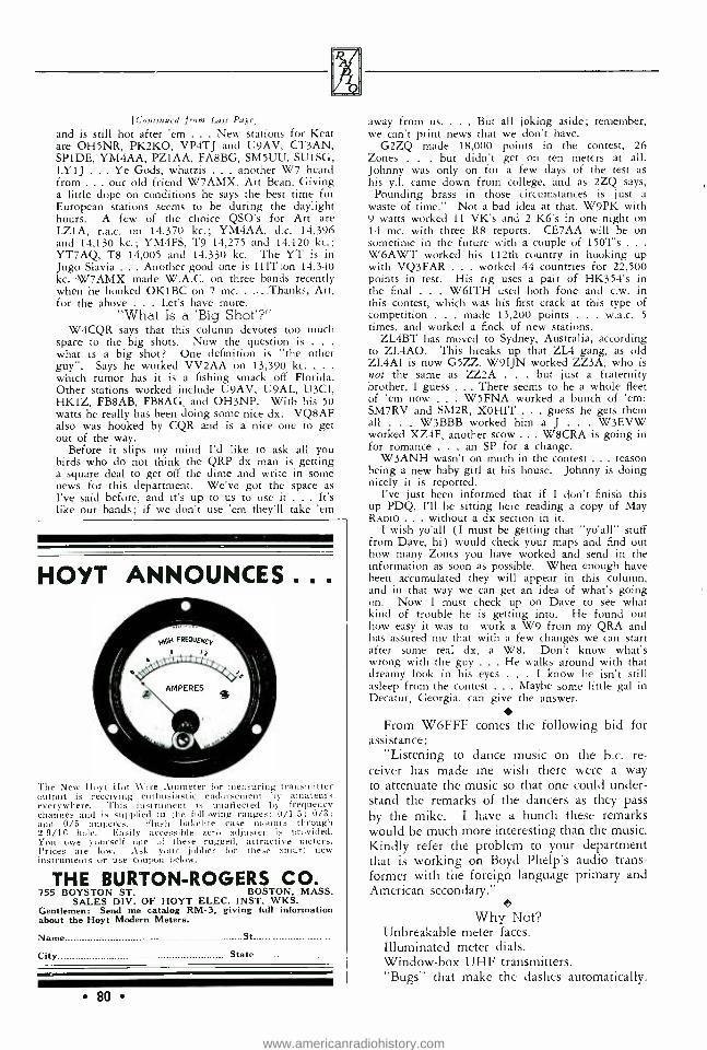
iR,
[Continued from Last Page]
and is still hot after 'em ... New stations for Keat are OH5NR, PK2KO, VP4TJ and U9AV, CT3AN, SP1DE, YM4AA, PZ1AA, FA8BG, SM5UU, SU1SG, LY1J . .. Ye Gods, whatzis . another W7 heard from ... our old friend W7AMX, Art Bean. Giving a little dope on conditions he says the best time for European stations seems to be during the daylight hours. A few of the choice QSO's for Art are LZ1A, r.a.c. on 14,370 kc.; YM4AA, d.c. 14,396 and 14,130 kc.; YM4FS, T9 14,275 and 14,120 kc.; YT7AQ, T8 14,005 and 14,330 kc. The YT is in Jugo Slavia . .. Another good one is IllT:on 14,340 kc. W7AMX made W.A.C. on three bands recently when he hooked OK1BC on 7 mc.....Thanks, Art, for the above . Let's have more.
"What Is a 'Big Shot'?" W4CQR says that this column devotes too much
space to the big shots. Now the question is .
what is a big shot? One definition is "the other guy ". Says he worked VV2AA on 13,390 kc. .
which rumor has it is a fishing smack off Florida. Other stations worked include U9AV, U9AL, U3CI, HK1Z, FB8AB, FB8AG, and OH3NP. With his 50 watts he really has been doing some nice dx. VQ8AF also was hooked by CQR and is a nice one to get out of the way.
Before it slips my mind I'd like to ask all you birds who do not think the QRP dx man is getting a square deal to get off the dime and write in some news for this department. We've got the space as I've said before, and it's up to us to use it ... It's like our bands; if we don't use 'em they'll take 'em
HOYT ANNOUNCES .. .
The New Hoyt Hot \Vire Ammeter for measuring transmitter output is receiving enthusiastic endorsement by amateurs everywhere. This instrument is unaffected by frequency changes and is supplied in the following ranges: 0/1.5; 0/3; and 0/5 amperes. Flush bakelite case mounts through 2 9/16 hole. Easily accessible -zero adjuster is provided. You we yourself one of these rugged, attractive meters. Prices are low. Ask your jobber for these smart new instruments or use coupon below.
THE BURTON- ROGERS CO 755 BOYSTON ST. BOSTON, MASS.
SALES DIV. OF HOYT ELEC. INST. WKS. Gentlemen: Send me catalog RM -3, giving full information about the Hoyt Modern Meters.
Name St
City State
80
away from us. . . . But all joking aside; remember, we can't print news that we don't have.
G2ZQ made 18,000 points in the contest, 26 Zones . . . but didn't get on ten meters at all. Johnny was only on for a few days of the test as his y.l. came down from college, and as 2ZQ says, "Pounding brass in those circumstances is just a waste of time." Not a bad idea at that. W9PK with 9 watts worked 11 VK's and 2 K6's in one night on 14 mc. with three R8 reports. CE7AA will be on sometime in the future with a couple of 150T's . . .
W6AWT worked his 112th country in hooking up with VQ3FAR . worked 44 countries for 22,500 points in test. His rig uses a pair of HK354's in the final . . . W6ITH used both fone and c.w. in this contest, which was his first crack at this type of competition . made 13,200 points . . . w.a.c. 5
times, and worked a flock of new stations. ZL4BT has moved to Sydney, Australia, according
to ZL4AO. This breaks up that ZL4 gang, as old ZL4AI is now G5ZZ. W9IJN worked ZZ3A, who is not the same as ZZ2A . . . but just a fraternity brother, I guess . .. There seems to be a whole fleet of 'em now . W5FNA worked a bunch of 'em: SM7RV and SM2R, XOHIT ... guess he gets them all . W3BBB worked him a J . W3EVW worked XZ4F, another scow ... W8CRA is going in for romance . . . an SP for a change.
W3ANH wasn't on much in the contest ... reason being a new baby girl at his house. Johnny is doing nicely it is reported.
I've just been informed that if I don't finish this up PDQ, I'll be sitting here reading a copy of May RADIO . without a dx section in it.
I wish yo'all (I must be getting that "yo'all" stuff from Dave, hi) would check your maps and find out how many Zones you have worked and send in the information as soon as possible. When enough have been accumulated they will appear in this column, and in that way we can get an idea of what's going on. Now I must check up on Dave to see what kind of trouble he is getting into. He found out how easy it was to work a W9 from my QRA and has assured me that with a few changes we can start after some real dx, a W8. Don't know what's wrong with the guy . . . He walks around with that dreamy look in his eyes . I know he isn't still asleep from the contest ... Maybe some little gal in Decatur, Georgia, can give the answer.
From W6FFF comes the following bid for assistance:
"Listening to dance music on the b.c. re- ceiver has made me wish there were a way to attenuate the music so that one could under- stand the remarks of the dancers as they pass by the mike. I have a hunch these remarks would be much more interesting than the music. Kindly refer the problem to your department that is working on Boyd Phelp's audio trans- former with the foreign language primary and American secondary."
Why Not? Unbreakable meter faces. Illuminated meter dials. Window -box UHF transmitters. "Bugs" that make the dashes automatically.
www.americanradiohistory.com

"GLOOMY SUNDAY"
'Twat the end of the contest and all through the shack,
Rose the odor of ozone and charring shellac. 20 was lifting and 10 had dropped out, But 40 was hot; so with a great shout, Our hero jumped up and retuned the rig, As a G5's CQ made the phones dance a jig. One call. then ten, and as many tens more, Yet still the G scorned the bottles' deep roar. To hex with a filter; if d.c. won't work, Then a.c. he'll get; so with a big jerk, The two mikes five thousand were tossed on
on the floor, And back at the G he went roaring once more.
/'s and VK's, HC and PY And others rapped in but were promptly passed
by. The limey was lazy; his rag chews were local: Our hero was wild; his blasphemy vocal. "Mr. God," prayed our hero, "I don't with to
trouble you, But I'll try to reform if he'll call TEST 'W'. I'll be fat as a goose; on all six I'll be hittin', 11 you'll wangle a contact for me with Great
Britain." And wonder of wonders, a brief QRZ; Then the Limey stood by and a short "three
times three" Brought an answering cheep from the far
shores of Dover, At the chime of the clock showed the contest
was over! -Linear
Why Not Such Contests, Too? For those who like marathons, the WAVE
DX contest is, at the time of writing, in full swing. Such contests have the merit of speeding up the key work and operating standard gen- erally of the younger and inexperienced par- ticipant. The idea fits in admirably with Ameri- can amateur radio, where traffic handling is comparatively open and unrestricted. In Aus- tralia and other British territories, where mes- sage handling in a third -party sense is taboo, such contests can have no value other than the one mentioned. Admittedly, the participant meets a lot of new DX friends, but it is only a fleeting glimpse, so to speak, involving a hur- ried interchange of serial numbers.
Far better would be contests conducted on experimental lines, such as the solving of tech- nical problems associated with transmitting and receiving apparatus, set by a number of exam- ining stations, the answers to be given in ro- tation within a limited time. Key and 'phone stations could take part with equal interest.
-The Bulletin (Sydney) .
Allen Fairhall, VK2KB, managing director of Australian broadcasting station 2KO will arrive in the U.S.A. in the middle of May with a "brand new 'o.w.' " (honeymoon). He ex- pects to drive across continent to New York, and is anxious to meet the many friends he has made in this country by amateur radio.
BOOST those IO and 20Meter Sigs ..
TEN TIJ11-.S 1 1 1 1 . SE.: 1 1 IV- ITV nn 10 meters -more than
that on 20! Signals you did -
i know were in there -u1 loud speaker volume!
Tremendous increase in receiving range on
these wavelengths. (highest possible
1. /C ratio. Lay -
,ut.coils,everj- thingdesigned
especially 10,20 Booster for these Sargent
two bands. No super reaches maximum efficiency on 10 or
20 meters without regener- ative input. Sargent 10.20
Rooster uses new regen- erative circuit & am-
plification, 2 tubes. Cat. No.ZS -2 -2.5 lt tube, Cat.
No. ZS ,6 6.3 v,.lt tubc-
FLASH - SARGENT Model 20 for 10 METERS We waited until u-e could offer you a design that would really Drag Them In on 10 meters. It is ready now.' Sargent Model 20-XSA, Code Word TWEXS, tuning range 9.5 $12-9° to 550 meters, $5.00 higher than our standard Model 20 -price complet $64.50 net. Price includes full set of R.C.A. tubes. No other changes from reg- ular Model 20. Ready for delivery now. A popular receiver of proven worth -the great-
est value in the field. NOTE: The Sargent 10 -20 Booster helps ALL supers- including our outs. E. M. SARGENT CO., 212 9th St., Oakland, Calif.
Net Includes
R.C.A Tubes
Allied Radío C O R P O R A T I O N
833 W. JACKSON BLVD.,Chicago Send mo your FREE 1936 Spring and Summer Catalog. Dept. J.
81
www.americanradiohistory.com

WANTED! YOUR SPECIAL PROBLEMS
We Build to Your Specifications:
#-RACKS
CHASIS
PANELS Complete
AMPLIFIERS
ETC.
* BAKE ENAMEL and CRACKLE FINISH
* RADIO ENGINEERING and DESIGN
RADIO DEVELOPMENT LABORATORY
3717 W. 54th Street
LOS ANGELES, CALIFORNIA
82
ALWAYS TAKE THE SHUNT OFF ON METER READING DAY
The cost of free electrons is mounting day by day, Epecially as the contest is now in fullest sway.
The power trust is cheerful, with our hero back on ten,
And the singing watt hour meter mocks the blue- bird in the glen.
"What wots the score if the score of watts if more than I can stand ?"
Our hero cried with last month's bill from power trust at hand;
But a tip from "Helpful Henry ", of knowledge dark and deep:
"Juice is dam expensive but copper wire is cheap. A shunt across the meter really slows that tattler
down; 30 seconds work, my friend, and you can go to
town."
When laws of economics and laws of mortals clash, The mortals take the hindmost and the devil takes
the cash. Our hero being human, cried out to darkest Satan:
"Get thee behind me, but push, for hot dx is
waitin'." Dx rolled in from far and near, and mighty was his
score; Reports were good; the log was full; but our hero
cried for more. The bottles' golden blaze and the pole pig's lusty
grunt Were merely an inducement to go add another
shunt To the all but useless meter, loafing gently in its box,
Whose sluggish perambulations the flaming final mocks.
Deep in oil the 72's were mounted in the sink, And neighbors' lights for miles around gave forth
a mighty blink. The tank coil nearly melted, and the transmission line
was hot As our hero slowly keyed his "West Coast" kilo-
watt. Time was ,and weeks rolled by, and our hero's heart
was light, But a cruel interloper came stealing in the night -
A minion of the power trust, on meter reading bent, Observed the shunts; "Aha," cried he, and straight-
away he sent A notice to the law to come and get our hero dear
And send him up the river for the balance of the year.
And so it was: the Judge was stern, and our hero is in hock,
And he'll stay there too, a year, no less, as meas- ured by the clock.
His mighty pole has fallen, and dust is on his bug, But there is joy on "40" since our Hero's in the
jug. So take heed, fellow amateurs, if you would be free
and gay; Always take the shunt off on meter reading day!
-LINEAR
A new 64 -page catalog featuring a large assort- ment of radio receivers, public address amplifiers and systems, radio service replacement parts, electrical appliances and electrical refrigerators, has been brought out by Wholesale Radio Service Co.
Copies are obtainable free of charge from their main office at 100 Sixth Avenue, New York, or any branch office.
www.americanradiohistory.com
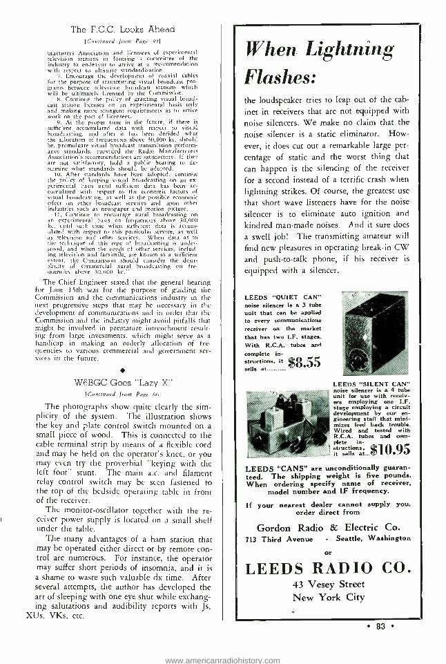
The F.C.C. Looks Ahead [Continued from Page 39]
ufacturers Association and licensees of experimental television stations in forming a committee of the industry to endeavor to arrive at a recommendation with respect to ultimate standardization.
7. Encourage the development of coaxial cables for the purpose of transmitting visual broadcast pro- grams between television broadcast stations which will be ultimately licensed by the Commission.
8. Continue the policy of granting visual broad- cast station licenses on an experimental basis only and making more stringent requirements as to active work on the part of licensees.
9. At the proper time in the future, if there is sufficient accumulated data with respect to visual broadcasting, and after it has been decided what the allocation of frequencies above 30,000 kc. should be, promulgate visual broadcast transmission perform- ance standards, provided the Radio Manufacturers Association's recommendations are satisfactory. If the, are not satisfactory, hold a public hearing to de- termine what standards should be adopted.
10. After standards have been adopted, continue the policy of keeping visual broadcasting on an ex- perimental basis until sufficient data has been ac- cumulated with respect to the economic factors of visual broadcasting, as well as the possible economic effect on other broadcast services and upon other industries such as newspaper and motion picture.
11. Continue to encourage aural broadcasting on an experimental basis on frequencies above 30,000 kc. until such time when sufficient data is accum- ulated with respect to this particular service, as well as television and other services. When data as to the technique of this type of broadcasting is under- stood, and when the needs of other services, includ- ing television and facsimile, are known to a sufficient extent, the Commission should consider the desir- ability of commercial aural broadcasting on fre- quencies above 30,000 kc."
The Chief Engineer stated that the general hearing for June 15th was for the purpose of guiding the Commission and the communications industry in the next progressive steps that may be necessary in the development of communications and in order that the Commission and the industry might avoid pitfalls that might be involved in premature intrenchment result- ing from large investments, which might serve as a handicap in making an orderly allocation of fre- quencies to various commercial and government ser- vices in the future.
W6BGC Goes "Lazy X" [Continued from Page (61
The photographs show quite clearly the sim- plicity of the system. The illustration shows the key and plate control switch mounted on a small piece of wood. This is connected to the cable terminal strip by means of a flexible cord and may be held on the operator's knee, or you may even try the proverbial "keying with the left foot" stunt. The main a.c. and filament relay control switch may be seen fastened to the top of the bedside operating table in front of the receiver.
The monitor -oscillator together with the re- ceiver power supply is located on a small shelf under the table.
The many advantages of a ham station that may be operated either direct or by remote con- trol are numerous. For instance, the operator may suffer short periods of insomnia, and it is a shame to waste such valuable dx time. After several attempts, the author has developed the art of sleeping with one eye shut while exchang- ing salutations and audibility reports with Js,
XUs, VKs, etc.
When Lightning Flashes: the loudspeaker tries to leap out of the cab-
inet in receivers that are not equipped with
noise silencers. We make no claim that the
noise silencer is a static eliminator. How-
ever, it does cut out a remarkable large per-
centage of static and the worst thing that can happen is the silencing of the receiver
for a second instead of a terrific crash when
lightning strikes. Of course, the greatest use
that short wave listeners have for the noise
silencer is to eliminate auto ignition and kindred man -made noises. And it sure does
a swell job! The transmitting amateur will find new pleasures in operating break -in CW and push -to -talk phone, if his receiver is
equipped with a silencer.
LEEDS "QUIET CAN" noise silencer is a 3 tube unit that can be applied to every communications receiver on the market that has two I.F. stages. With R.C.A. tubes and
complete in- structions, it $8.55 sells at
LEEDS "SILENT CAN" noise silencer is a 4 tube unit for use with receiv- ers employing one I.F. stage employing a circuit development by our en- gineering staff that mini- mizes feed back trouble. Wired and tested with R.C.A. tubes and com- plete in-
. (IO st it sells at... 1
LEEDS "CANS" are unconditionally guaran- teed. The shipping weight is five pounds. When ordering specify name of receiver,
model number and IF frequency.
If your nearest dealer cannot supply you, order direct from
Gordon Radio & Electric Co. 713 Third Avenue - Seattle, Washington
or
LEEDS RADIO CO. 43 Vesey Street New York City
83
www.americanradiohistory.com

Calls Heard [Continued from Page 451
LY1J: OH2PS; OH3NP; OH5NG: OH50A; OH7NI; OH8NA:
OH8NF; OK1AA; OK1BC; OK2DF; OK2KJ; OK2K0; OK2PL; OZ3FL: OZ7FJ; OZ7G; OZ7N: OZ7SJ; PAOTSK; SM5UM; SM6VX:
SPICS; SPICY; SP1DE: SPIEB: SU5FL; U1AB; U1AN; U1CN; U5AN; USCC: VE1B; VE1HJ; VE2EE; VE3HC: VK2NY; VK2VU: VK3EG; VK3F0; VK3JK: VK3RE: VK3XP; VK5HG: XZA7C:
YL2BG; YR5JS; YR5VC; YR5VI; YT7KP; ZA1H; ZR1H; ZC6CN:
ZLr1FE; 1GX; 1UP; 2FA; 2JA; 2KK; 20Q; 3AB; 3JA; 4F0.
Paul Bauman, W9IJN, 3520 35th Avenue, Minneapolis, Minn.
February 12 to March 12
(28 mc. phone)
0Á4B. (28 mc.)
CM2FA: CP1AC; EA4A0: FASRG: F8E0; FSVS: G2PL; G5BY;
G6LK: G6QB; G6ZU; HJ3AJH: K5AL; K5AY: LU9AX; 0A4J: OH5NG: OK1BC; OZ2M; PAOAG; VK3BD; VK3YP; VP5PZ;
ZS1H.
T. J. Wakimoto, J3FK, 873 Kami- Kosaka, (near Osaka) Japan
February 2 to 16
(28 mc.)
W 6BAY: 6BW; 6BNU: 6CWJ: 6CXW; 6D10: 6EAV; 6EWC;
6EZB; 6FMY; 6FQY; 6GCX; 6G0Y: 6GZU: 6HR: 610J; 6JJU: 6JN; 6JNR; 6KBD; 6KJG; 6FZY; 6VB: 7AVV; 7BYW; 7IFM: 9UIG. - K6CRU: 0A4B; OK1RK; VE5BI. - VK 2E0; 2HZ: 2LZ; 3BD: 3BQ; 3CP; 3YP; 3ZC; 4E1; 5A1; 5WK; 5ZC; 6SA. - ZL1CD; ZL1DV; ZL1GX; ZL3AJ.
E. De Saedeleer, ON4DS, 103 Avenue Lippens, Knocke, Belgium
February 7 to March 1
(7 mc.)
W2EGC -8: W3AGI -8; W3FGK -8.
(14 mc.) W 1AU -6: 1BXC -6; 1CFC -9: 1FSN -8: 1GOU -9: 1HWP -8; 1WV -6; 2Á1W -9; 2AZB -8; 2811M -8; 2CUQ -8; 2FHM -6; 2GFZ -6; 3EQA -7; 3ENX -8: BDKC -8. - LU6JR -6; VE1BA -6: YM6AF -8.
A fairly decent job of poising unbalanced meter movements, where one of the poising weights has been lost, can be done by applying enough white lead (with a tooth -pick) to pinch hit for the missing weight.
TRAN RMERS and CHOKES
Send for complete Refer- ence Guide of Better Transformers and Chokes for all Receiver and Trans - miner Purposes.
UTAH- RADIO PRODUCTS C ns St., Chicago
84
HAMFESTS AND CONVENTIONS Wisconsin
The Milwaukee Radio Amateurs' Club will hold their thirteenth annual QSO party, May 16, 1936, at
6:30 p.m., in the Elizabethan Room of the Milwaukee Athletic Club, N.E. corner Mason and Broadway.
Mr. E. A. Roberts, W8HC, A.R.R.L. Director of
the Central Division, will give a vital talk on Am-
ateur Radio. The program will also include Dinner, Refreshments, Prizes, Entertainment and a revival of
the "Loyal Order of the Derby ". Reservations $2.00. For information rnd reservations write to:
Herbert L. Baker, 'X'9GSP, Secretary 3922 N. 24 Place, Milwaukee. Wis.
Texas The Radio Amateurs of Abilene are inviting all
the Hams in Texas to be with them for a Ham - fest in Abilene on the 25th and 26th of April, the affair to be staged in the Textile building in West Texas Fair Park on South 7th and Portland Ave.
Will start gathering up the clan about 5:00 p.m. on the 25th.
There will be no speech making, but just a gath- ering of good -fellows, for discussions on their dif- ferent radio problems, etc.
Kentucky On May 23, 24, 1936, the 7th Cavalry Brigade
(Mechanized), Fort Knox, Kentucky, under the com-
mand of Colonel Bruce Palmer, and in conjunction with the Louisville Amateur Transmitting Society,
will act as host to the amateur radio operators of the
Middle West. This will be an official Kentucky con-
vention of the Central Division of the A.R.R.L. Special low rail rates will be in effect.
Men attending the convention will be quartered in Army barracks and fed in Army messes at a cost
of $2.50 for quarters (one night), five meals and a
registration fee of 50c. People attending who wish
to bring their families can be quartered and messed
in the Central Mess for about $2.50 per day, and of
course there are plenty of hotels in Louisville, 32
miles away.
Pennsylvania The U.H.F. Club of Philadelphia will hold its first
annual hamfest on Saturday, May 16th. For infor-
mation drop a postcard to W3AUY, or listen for
Westinghouse W3XKA on Tuesday nights (55.5 mc.) if you live in or near Philadelphia.
Wisconsin The Fox River Valley and Affiliated Radio Clubs
will hold their fourth annual picnic and hamfest at
Round Lake, Wis. on June 21. Round Lake is located 1 mile west of Dundee and 25 miles west of Sheboy- gan, Wis. Program will include ball games, con-
tests, free eats (and beer!), prize drawing, and dancing.
Michigan The Central Division Radiophone Association is
sponsoring a hamfest to he held at the Hotel Tuller in Detroit on June 14th. Everyone is invited, am- ateurs and y.l.'s and ex- y.l.'s and s.w.l.'s alike.
www.americanradiohistory.com
A FEW of the HUNDREDS of LEEDS BARGAINS If you don't see it WESTERN ELECTRIC 3:1 uucascd attrli, tr,,,.former.. 49c WESTERN ELECTRIC cased cm- densers, Sun v. working 1 mfd 1Oc 2 mfd 15c PREMIER MIDGET Magnetic speak ers. 3" 90c; 5" $1.00; 6 "- -$1.20 LEEDS all brass key with 'e" con- tacts 95c; with nave km.:b $1.15
ANTENNA WIRE - COIL WIRE Soft drawn tinned c leper. Sift drawn enameled copper. llard drawn tinned wire; per hundred feet No. 14 40e; N. 12 55c; No. 10 85c
LEEDS carries a complete line of General Radio Amateur accessories and laboratory apparatus. Bulletin N' +. 936 mailed on request. GENERAL RADIO coil forams type 677.0 price 50c; type 677 -Y price 75c. G. R. amateur accessories always in stock. G. R. dials, with fluted knobs 4" -- $1.50: 3H t" $1.25; 234" -$1.00. GENERAL RADIO .0005 variable condensers, like new 75c
THORDARSON TRANSFORMER special, 1200 volts CT 200 ma. 5 v. 3 amp. 7% v. 3 amp. 214 v. 10 amp. a
quality case job $2.45 Thordarson 12 hen. 250 ma choke 1.95 Thordarson cased class B transform- ers input and output. For 46's. Per pair $6.17 For 210. Per pair 8 23 For 203 -A. Per pair 17.64
listed, write us and get our low net prices LEEDS cased oil impregnated filier ciatdurr $1.10 1 mid 1100 v " mid. $1.45
1.45 1 till 1500 v 2 mid. 1.95 1.75 1 mfd '01111 v 2 ink!. 2.45
New RCA transmitting tubes in stack. RCA 801 $15.00. RCA 805 $18.00
NEON BULBS. t4 watt - watt - 1 watt 29c 2 watt ne m u -r argon bulbs 45c
LEEDS offers outstanding values in quality transmitting TUBES, backed by nitr name and guarantee. *203 -A $8.45 "838 11.75 866 1.50 f *841 2.95 304 -A -UHF 9.45 *852 11.50
t *801 2.95 866 -A 1.95 "Graphite Anode Tubes
tlsolantite Base Tubes Shipped b.) Express Only
EED "The Horne of RADIO
LEADS THE FIELD World livide Service to Amateurs
43 Vesey Street New York City
Telephone Cortlandt 7 -2612 Cable Address: "RADLEEDS"
New Cammunications Products -high Yictrnn ,ckttmn transmitting in-
clue;ors in sock. Tune with 50 mfd. 160 meters $2.50 80 meters --$2.50
10 meters -$1.25 20 meters -$ .75
Johnson sidewiping tact, 50 watt sockets New Aerovox dual midget electrolytic condensers, 450 v. working 4 -4 mfd. 70c; 4 -8 mid. 79c; 8 -8 mfd. 88c
New Aladdin air tuned I.F. transformers in stock ALL STAR transmitting kits in stock. MEISSNER FERROCART iron core t rap sfnrnters. -these units will increase selectivity, double the gain, increase signal, lower set noise. 175 $1.18 - 262- 370 -156 1:c. each... Meissner I.F. transformer,: tuned, all ranges as above; cacti J Meissner R.F. choke shielded nod unshielded; 2.5 mh to 80. mh.
Meissner Junior trimmer, ceramic base; 10 tunt to 475 mmf working range. Bulletin and price list mailed rin request.
TRIMM 2000 ohm phones $1.80 10110 ohm $2.25 TRIMM featherweight $5.88 FROST 2000 ohm $1.45 FROST 3000 ohm $1.65 DX 20000 phut imp $2.65 W ESTERN ELECTRIC
type l' -11 $3.95
REVISTA TELEGRAFICA A MONTHLY ARGENTINE RADIO PUBLICATION
Established 1912
A radio magazine, written in Spanish, with a large circulation in Central and South America and Spain.
The editors of RADIO say, 'Rei-i.uta Telegreifica seems to cover a wider field better than any magazine printed in English; it is undoubtedly the
finest magazine of its kind south of the Rio Grande."
Covers practically, technically, and commercially the entire field of radio and wire, telephony and telegraphy in South America.
SUBSCRIPTION PRICE: $1.50 (U.S.) PER YEAR
REVISTA TELEGRAFICA General Offices
Peru 165, Buenos Aires, Argentina
85
e
www.americanradiohistory.com

Free Handbooks! Each month we will pick at random from
the latest callbook several amateur calls and list them somewhere on the "Marketplace" page among the classified ads. If the holders of the calls listed will drop a postcard to RADIO to the effect that they have noticed their call, they will be mailed free a copy of the 1936 "Radio Handbook ". This card must be postmarked be- fore the 15th of the month on the cover of the issue in which the call appears.
QRP DX RECORDS When VK3PG first started transmitting in
1933 he had several QRP contacts with VK3NQ, who was interested in QRP records. Using the 80 -meter band, and with the stations 90 miles apart by air line, 3NQ called one day, employing only an old dry cell showing half a
volt for plate supply. The signal was R2/3 at
3PG, with fading, but distinctly readable. Time was 15.30 e.s.t. Since then 3PG has devoted most of his time to 20 -meter dx, with 180 volts of B battery for plate supply and a 201'A
With ASIATIC of Me ARCTIC
At their base in the Bay of Fun - fly, the Bowdoin Arctic Ornitho- logical Expedi- tion are using Astatic D -104. The above pho- tograph shows George R. Cad- man, Chief op- erator, at the controls of the short - wave transmitter. The D -104 is licensed under Brush Develop- ment Company Patents. Fully guaranteed.
LIST PRICE $22.50
THE
D-104 Known the World Over
Wherever ruggedness, durability and speech range quality are nec- essary, the D -104 is the choice of expert and veteran amateurs. The recent flood disasters proved how many D -104's were in use over the U.S. And from all points of the globe, like this Arctic Expedition, come reports of D -104's fine per- formance under all conditions. A GRAFOIL CRYSTAL Microphone that cannot be excelled for steady, long use by the amateur who wants both performance and economy.
Ask Your Jobber for Details
Astatic Crystal Microphone Laboratory. Inc.
Youngstown, Ohio., U. S. A. Pioneer Manufacturers of Quality
Crystal Devices
Ask the HAM who OWNS ONE 1
86
as p.a. in a "Groyder lock" transmitter. Usual input is 31/2 watts and maximum 4 watts.
In January, 1935, w.a.c. was achieved with this power, and between February and Novem- ber that year contacts with stations other than VK and ZL numbered 350. Over 50 countries were worked, and all continents five times. 3PG reports having raised Europeans with a
shade over one watt. In May, 1935, he con- tacted PAOAZ in Holland at 3 p.m. local time, getting a report of QSA5 and a request for power -reduction tests. Input was reduced to 2 ma. at 45 volts, and to 3PG's astonishment the Dutchman reported no difference in the signal. The transmitter was then tried with 221/2 volts on the plates, but oscillation failed. On the following day, the transmitter was made to function on the 221/2 volts, but after open- ing up on 45 volts the Dutchman reported no signals at reduced voltage.
With normal power of 31/2 watts, 3PG has been reported R9 from W6KRI, R8 from Jap- an, Jamaica and the Philippines, R7 from Bel- gium and R6 from several European countries. South African and South American reports have been under these, but still around Q5 R6. VK3PG is a dx QRP station making the most of his antenna system. Having plenty of ground space, being on a farm in Casterton (Vic.), he uses a directional V array 52 feet high at the apex and sloping to 30 feet at the open ends of the V.
Length and clear surroundings appear to con- tribute to the good results obtained, for as much as 330 feet of radiator has been used in each arm of the V with improved results. The moral is that the country amateur with space available and plenty of wire can do the trick on low - power dx, particularly on 20 meters, but the city amateur, unless he owns a lot of land in a
good location, is handicapped, and must turn to power for his results. The old rule of "a good antenna is more than half the battle" still holds good, whatever the radio application.
-VK2NO in The Bulletin (Australia).
Diathermy Furor [Continued from Page 7]
cords to the pads. Measurement of this current may facilitate initial adjustment, but this is off- set by the fact that many physicians will be in- clined to take altogether too much stock in the meter reading and not pay enough attention to what is happening to the patient. The r.f. meter may be incorporated, but it is a refinement not necessary for proper treatment.
We were accused of showing contempt for the medical profession, and of doing them "un-
www.americanradiohistory.com

told harm ". But we have received a large num- ber of letters from doctors, mostly in the coun- try and small communities, expressing their ap- preciation of an article that enabled them to get a diathermy machine built at a price they could afford. Thus this means of treating the sick has been made available to a greater number of physicians than would have been the case oth- erwise. As for our expressing "contempt" for the intelligence of the physician, we merely are aware of the average doctor's lack of radio knowledge. That is no reflection on his profes- sional ability. One of our best technical men doesn't know his liver from his gall bladder; that does not mean he is not a good radio man.
One manufacturer tried to make much ado about the patent angle. However, there is noth- ing to worry about from that standpoint just so you don't go into the manufacturing of the machines on a large scale. There is no law that prevents you from building a machine "to or- der" at so much an hour, the doctor paying for the parts. Most of the composite police trans- mitters in use today were built that way to get around patent difficulties.
Several requests have been received for in- formation on a "radio knife" (for bloodless surgery) attachment for the diathermy. We hesitate to give the data because of the dangers involved and because many doctors condemn their use. We will state, however, that such an attachment may be used with this machine the same as with any similar diathermy machine of commercial manufacture.
On the Road to Cairo 1<.nnttn,,ed from Pate
those in attendance at the next conference .. .
in fact, they could ill -afford even to ask that they be sent to Cairo. Wise is he who stays in his place, once he has been put in his place.
No living person could accomplish less for the amateur than has been accomplished at some previous frequency -grabbing gatherings. No liv- ing person would relinquish, at this time, what was relinquished years ago, "in the interests of commercial development." Do you, Mr. Amateur, ever stop to think what RADIO has done to enlighten you as to the true status of your cause? We ask no thanks, want none; you must do your part to help make certain that none but the brave will represent the amateur at Cairo.
A short time ago a "Cairo Survey" was under way. Deplorable is the fact that such few ama- teurs have participated in this survey, a con- temporary amateur publication says. Less than fifty amateurs played an active part in this work. And the amateur world is roasted over the coals for not showing more interest in what is termed as its ultimate salvation. Why so few amateurs have taken part in the survey check
[Continued on Next Pagel
tNAol- -
V .1
lj .00 il, ,,onjlliliill /7 4
il
/,-.44, `. . ,;/,'' __ - _ -
- --the Circuits go 'round & 'round
Service any set with a song . .. no matter how involved the circuit ... that is ... if you've been tipped off to use CENTRALAB replacement parts wherever Volume Controls and Fixed Resistors are indicated.
Get off the "merry go round" of service headaches. Ask for and insist on CENTRALAB
RADIOHMS For smooth ... noiseless attentu- ation ... the ideal Volume Con- trol replacement.
RESISTORS Baptized in fire at 2500' F. Noise- less- Moisture proof .
SUPPRESSORS for top efficiency for both radio and motor.
The new 1936 VOLUME CONTROL
GUIDE is out.
See your jobber for a free copy.
Iflry Rodin Srrrire /Van +3t hra+.vwbrathe
Milwaukee, Wisconsin RADIOHMS
SUPPRESSORS FIXED RESISTORS
WAVE CHANGE SWITCHES
87
www.americanradiohistory.com

(Comm/err/ from La t Page]
is easy to understand, by those who have been in amateur radio long enough to understand !
In the first place, it is the Congress of the United States alone which can assure U.S. am- ateurs of their place on the air. This the amateurs have been told, over and again, in these pages. That is one reason why there is practically no interest in the Cairo Survey. In the second place, there is no need for such a
survey, no matter how severely some may de- nounce us for advancing such a declaration. Reading the contemporary amateur press one learns that it is necessary to report how much of the commercial activity in the short wave spectrum is useful, economical, and practical. Amateurs are asked to log the sta- tions, state how many hours in a day these stations are on the air with traffic, how much of the time is devoted to v- wheeling, free- wheeling, and squealing, etc. Congress can easily subpoena each owner of a commercial sta- tion to bring to the proper committee complete station logs, showing how much of the station time is devoted to genuine traffic handling. Therefore, what folly to ask the amateur to spend 24 hours of his daily time for a spotty recording of this matter for a "Cairo Survey ". The information is readily obtainable on de- mand ; why make a sucker of the amateur?
Let us therefore devote our time and our attention to the Congress, from whom more can be expected in a single day than can ever be had from all of the amateurs in the world combined. It is time that the amateur face this matter fairly and squarely, no longer permit himself to be misled by being asked to partici- pate in utterly useless and childish endeavors, and to devote his time to a non -effective cause; whereas, on the other hand, a tremendous amount of good can be more quickly accomp- lished by merely banding ourselves together and
DON'T WAKE UP the WHOLE
HOUSE Just because you are INTENT on getting some distant foreign station LATE AT NIGHT .. use
CANNONBALL HEADSETS and YOU WILL RECEIVE BETTER RESULTS and THE FAMILY WILL NOT BE DISTURBE3.
Order from your dealer. If he cannot supply you, we will.
WRITE FOR ILLUSTRATED CIRCULAR L -3
C. F. CANNON COMPANY SPRINGWATER, N. Y.
88
going to our Congress for aid. Everybody who reads RADIO knows that the
commercial bands are idle for a goodly portion of the time and that the money expended for oil to grease the r -wheels represents a greater sum of money than that which is received during those hours when no traffic ticks from the tape. That's old stuff! And, knowing that the conditions exist, why investigate them? The thing to do is to get action . . . and action comes only from those who have authority to act for us !
Any body of amateurs can appear before Congress and request of it the same hearing which would be accorded any other body of citizens, large or small. In this instance, strength is not represented numerically; a good cause has often been brought to bear fruit by the ef- forts of a lone few men, whereas, on the other hand, organized groups have sometimes utterly failed in accomplishment, simply because the lawmakers were fully aware that the organized -oup represented a job -holding or racketeer-
ing outfit of one kind or another. Send a del- egation of sincere amateurs to Congress send men who understand amateur radio, not men who are in it for the mere sake of holding high - salaried jobs, and you will not need worry at the reception which will be given them when their requests are made.
Let no amateur believe that it is our desire to weaken the structure of A.R.R.L. The or- ganization, large in numbers, yet representing only one licensed U.S. radio amateur in three, according to its own disclosures, cannot be ex- pected to wield the big stick in Congress which can be more effectively made to strike home if all amateurs, A.R.R.L. members or no, band to- gether in a common drive on the Congress of the United States.
Rather than waste our time on surveys that can accomplish naught (and which, if the sur- veys disclose no "holes" to which displaced stations might move, will constitute a beautiful weapon for our enemies) let the amateur devote this same time and effort to persuading his Congressman to bring about the appointment of a committee to investigate the activities of commercial traffic handling on the short waves. Then, with this record a part of the official line
BUY IT ON TIME DO YOU WANT YOUR NEW RECEIVER NOW? Buy it the east- iav m our Hinds "Easy Payment"
Plan. Write quickly for complete details.
HINDS & EDGARTON 19 S. Wells Street Chicago, Illinois
(Est. 1914 - Management by W9APY -W9WR)
www.americanradiohistory.com

of business of the Congress, it will be made evident to every Congressman that something is decidedly rotten in the method of frequency allocation. Far more effective would it be to have the Congress supplied with its own facts, by its own committee, rather than to trust to the reports which a small group of amateurs may make to a job -holding publishing house. Congress understands the publishing business, it understands organizations, cliques, leagues, and rackets only too well. And, likewise, it understands human nature. The more effective method of convincing our Government that we are forced to squat in an unjustifiedly narrow ether lane is to urge the Congress, at its forth- coming session, to bring about the means where- by an official Governmental investigation be made of commercial short wave activities.
It is altogether likely that such a movement would be decried lustily by those in control at Hartford. The A.R.R.L. administrators would not fit into this picture, you see. But let's come forth with the cold facts ... even though it may hurt ... The Congress of the United States be- gins where the Hartford crowd leaves off, and we will accomplish more by going to those who make the laws, than by paying tribute to those who everlastingly try to sell us the proverbial cat in the bag.
U MIDGET RELAY' RACKS
_lust the rack you have wanted to set on your table. It is an ideal unit for that low pow- er transmitter, ampli- fier, P.A. system, or test panel. Made of heavy gauge sheet steel. Finished in baked on black crackle enamel. Drilled to fit standard 19" rack panels. Light in weight a n d sturdily built. Shipped knocked down with necessary self tapping screws. Easy to assemble.
Na. 1248- Over -all height 25" -Width 20" -Depth cf base 10" -Panel Space 21 ". List $6.50
No. 1249- Over -all height 32" -Width 20" -Depth of base 12" -Panel Space 28 ". List $8.50
Write for FREE circular describing i,ther .size: and l \pes of Relay Racks and accessories.
BUD RADIO INC. 1937 E. 55 :h STREET CLEVELAND, OHIO
It seems that the longitude and latitude are not enough for the F.C.C.; they want also to know horn high. up. A commercial station has been granted permission to move its transmitter from the 5th floor of the building in which they are located to the 4th floor of the same building.
Brass Pounders REJOICE!
Here's a C -D capacitor to gladden your heart An outstanding value highly suitable for low power x- mitters and power amplifiers. Can be used as grid or plate blocking condensers as well as for efficient by- passing of radio frequency currents around any device or D.C. meter. Short path connections used in construction. Capacity accurate to close commercial tolerances. The Type 9 Cornell -Dubilier Mica Condenser is world - famous for its excellence in 1000, 2000, and 5000 volt ratings.
Your local C -D jobber has all the dope - ar .rend for complete dereriptire literature.
CORNELL-DUBILIER CORPORATION
4373 BRONX BOULEVARD. NEW YORK
NEW LOW PRICE
}(INPERITE CURRENT AND VOLTAGE
REGULATORS Amperite replacements for AC- DC sets now LIST $1.25. Amperite 3-40 can replace AC -DC set regu- lators 50x3, 300, and SB. Also new low price on replacements for 2 -Volt Battery Sets, List $1.60
Write for CHART CV.
AMPERITECO. 561 BROADWAY NEW YORK
89
www.americanradiohistory.com

Article Contest We wish to thank all those amateurs
who have sent in contest -manuscript. Be-
cause of the large number of entries re-
ceived, it has taken longer to go over all
of them than had been anticipated. So
many excellent ones have been discovered that the judges are going to experience considerable difficulty when the time comes to narrow the selection down to
one. The winner will be announced next month.
RADIO TOWER MAKES RAIN
If the Government should ever contemplate a Drought Control Administration, we may yet
see forests of radio towers rearing their heads in the barren places if the recent rain -making experience of Cincinnati's Station WCKY offers any guide.
That the phenomenon produced where all pre- vious efforts have failed in coaxing the healing waters from the sky is vouched for by Charles Topmiller, chief engineer of Station WCKY. It must be noted that the results were not due to any attempt to produce rain, but were the aftermath of the erection of a new 350 -foot Vertical Radiator.
When the slender steel tower had been raised and guyed into position, rain clouds in passing struck the upper reaches of the tower. Immedi- ately rain started falling for a radius of thirty feet around the tower, and the precipitation occurred on four consecutive days.
Scratchi wants to know what he is offered for one slightly used spilt -stator condenser, 100 ltl.tfd. It spills over every time he modu-
lates his rig.
BIG 1936 WHOLESALE CATALOG FREE!
1:_ärÿ_"
Rf'TIIÑ APPl1I _arc4oa, loll -Icsa McGee st. Kansas City. Mo.
164 pages - Radio. Electrical and Refrigeration Equipment at lowest net prices. A catalog of great value to every deal- er, service man and amateur. Complete sets, parts, ama- teur and commercial appa- ratus. Write today.
BURSTEIN - APPLEBEE CO. Kansas City. Mo.
1012 -14 McGee Street
90
28 and 56 Megacycles [Continued from Page 43]
period at a given latitude on the sun differs from other latitudes, increasing from the equator to the poles, and in latitude 60° is greater than at the equator by about 20 per cent. Sun spots occur only in two zones extending from about latitudes 0° to 30° on either side of the equator, being in the higher latitudes at the beginning of the cycle. Thus, the correlation is not an entirely simple problem!
56 Megacycles J2HJ will be glad to arrange with some
U.S.A. station for 56 mc. schedules. He is us- ing a pair of 800's on 56 and 112 mc. Several W stations with a few hundred watts of crystal controlled signal on 56 mc. might arrange their schedules to include J2HJ.
W7AVV is putting twenty watts into a low powered 56 mc. crystal controlled rig, and using his ten meter superheterodyne on "five", but no real dx worked yet.
W9NY spent six weeks calling on "five" with low power, but without success. He will continue his work. We suggest using one of these G.E. electric clocks that will turn the set on and off at any 15 minute points in twelve hours, thus permitting some time for the YL.
W6JJU, XE1AY, W6DOB, W3SI and some of the other migrants to 56 mc. promise con- centrated work now. W3SI claims a whole kilowatt on 5 & 10. Get in touch with them for schedules and help by listening. A good share of the work is planned for week -ends.
Another member of the 56 mc. dx group is G6CJ, who is putting a crystal controlled rig on the air on about 56,300 kc. mostly. The receiver is a crystal gate superhet (sniggle sig- gle to you) ; so don't expect "five meter" QSL cards from him if you are using a self- excited phone. He will try mainly for W -VE con- tacts. As an aid to picking him up, he will excite the ten and five meter aerials simultan- eously.
Don't forget, when 28 mc. is coming over as short a distance as 400 miles, 56 mc. may be good at 1000 or 1500 miles; also, that dx on "5" might come through whenever other W stations can be heard on "10 ". The best time
MAC KEY @ $7.95, finest speed key built ;
MAC OSC @ $3.95, ac /dc oscillator. Tone control; MAC CORD $1.00, navy spfn speed key cord; MAC MARINE receiver 550 -850 meters. ru intd? Few deluxe MAC KEYS @ $15.00 fm me di. Wri me. T. R. McELROY, 23 Bayside St., Boston, Mass. If u by Mac Key wri me for xmy ipt & dsrb ifn.
www.americanradiohistory.com

will probably be some time after the sun has passed the midpoint of the path, or 9 to 11 a.m. Eastern time for Europe and somewhat later in late spring and early summer.
Minority Report [Continued from Page 31
There shall be an Executive Committee con- sisting of the officers of the League which shall meet from time to time to conduct the affairs of the League within its jurisdiction. The Commit- tee shall keep a record of its meetings and actions and shall report at every meeting of the Board of Directors.'' I recommended that the following words be added
to the Constitution, Article 4, Page 2, at the end of said article: "Nothing in this section shall operate to prevent any director from publishing a division bulletin and from accepting advertising, or from main- taining a subscription price to cover the actual cost of printing and distributing such a division bulletin." The majority report makes this same recommendation but does not make provision for incorporating it in the Constitution.
The majority report states: "We believe that should it be necessary to elect a new President or Vice -president, he should be chosen from a group of men who have passed the test of ap- proval by members of the League, as expressed by their election to the Board of Directors. Therefore, with reference to Article III, Par- agraph 2, we recommend that the words 'from among their number' he inserted after the words 'Board of Directors'." I disagree with the recommended method of select-
ing the President and Vice -president from the mem- bers of the Board, or "from among their number" as stated, and believe that the President and Vice -pres- ident should be chosen from the membership, and should be elected by mail similar to the method of electing the directors, and the nominations should be made by petition as in the case of directors.
Make This
OSCILLOSCOPE Low cost, easily constructed kit for amateurs and experimenters. With it view and demonstrate wave form! Use it for making resonance and r.f. indicators and audio oscil- lators. Comes with an improved bril- liant tube having unexcelled fidelity re- sponse and long life. NOW BETTER AI)AI'TEI) TO R.F. O1'ERATION.
$2.00 net Prepaid with
improved tube, clips mirror and
motor adapter.
Nothing like it for accuracy and perform- ance. Definition of wave form clean-cut and clear. See at your jobber or order direct at this low price.
OSCILLOSCOPE KIT
THE FINISHED JOB
SUNDT ENGINEERING CO. 4236 LINCOLN AVE. CHICAGO. ILL. (Affiliate of Littelfuse Labs. Makers of Instrument Fuses - Radio and Auto Fuses -High Voltage Fuses- Aircraft Fuses -Fuse Mountings - Neon Potential Fuses and Indicators.)
I believe it is not essential that the annual meeting of the Board of Directors be held in the city in which Headquarters is located, and that "in the city in which the Headquarters of the League is located" should not be inserted (as recommended by the majority) after the words "annual session ". Also in connection with this, all the meetings of the Board held in Hart- ford should be held in the headquarters building, and not at a "club" building four miles away. The reason for doing this as was brought out in conversation with Chairman Bailey, was to prevent any remarks made in the Board meeting from being overheard by
[Continued on Next Page]
i
SPECIAL! INVENTORY CLOSEOUT OF USED TRANSMITTING TUBES
Tubes are all guaranteed and careful packing insures safe delivery.
W.E. 212 -D $9.95 RCA 860 $10.95 RCA 852 7.95 RCA 851 69.00 Used 845 5.95 RCA 204A- 22.00 New Raytheon, RCA and Eimac Transmitting
Tubes in Stock.
PEERLESS SHORT WAVE CONVERTER . . Makes a short \wave Superhet of your present broadcast re- ceiver .. just connect two wires to aerial .and ground of receiver and plug in converter to any -AG or DC outlet.
Simple to Attach and Operate. Covers Complete Short Wave Band from 15 to 200 Meters.
No plug -in coils. - COMPLETE with Two Tubes, net $7.95
PEERLESS double button microphone, free. I,. "ponsc all I,, 5000 cycles, pure gold butt-a contacts, Model X $3.75 New BLILEY 20 -meter type HF -2 crystals, net 7.50
All Type BLILEY crystals in stock. 2 mfd. 21)1111 volt filter condensers.... 2.45 ti mfd. 21)0(1 volt filter cnndeners 2.95
1
Uncle Dave's Radio Shack 356 Broadway, Albany, N. Y., U.S.A.
Cable Address "Uncledave" Long Dist. Phone 4 -5746 Include 20' ̂ , deposit with orders Prices F.O.B. Albany Send for New Ham Cat. -justout Foreign trade solicited
Special Radio Services by Robert S. Kruse, E.E.
-For the Professional: Apparatus and station designs and improve- ments. Construction of special apparatus. Problems involving cathode ray equipment.
-For the Amateur: High -grade discontinued commercial trans- mitting equipment. "The Answer Factory," a low -cost informa- tion service on operating and constructional problems. Quotations on request.
ROBERT S. KRUSE GUILFORD, CONNECTICUT
(Near New Haven)
91
www.americanradiohistory.com

[Continued from Last Page]
any member of the staff at Headquarters. But I do
not believe that this is the main reason. The reason behind this unusual strategy is, in my opinion, that the Secretary is always on the alert against a clash in opposition to his authority. It seems to me that it
is intended that the Directors shall be kept as far away from Headquarters as possible. Also the rental paid for the headquarters office is too high when proper consideration is given to other factors such
as the value of the property and its location. The rental paid should secure the use of the entire build- ing. This is a two -story building and the ground floor is not suitable for business.
If this5 is adopted it would be left to the discretion of Headquarters when there should be a meeting. I
believe that special meetings of the Board should be
called when a quorum of members of the Board de- mand it.
In one place the report of the majority remarks that motions appropriating surplus can only originate in the Board of Directors.
The Secretary's report of the Executive Committee meeting of December 6, 1935 informs us that War- ner had taken upon himself to resurrect an unpaid account due to the then Vice -president Stewart, who had made no claim for it; Warner had made up this account by digging up some old correspondence dated between October, 1923 and August, 1927, amounting
-.The Constitution requires quarterly meetings of the Board to he "called" ; three of such meetings are customarily called and adjourned for lack of a quorum. The majority recom- mend that the Constitution specify that such quarterly meet- ings "may be" called.
The Most Com-
plete Callbook
Ever Published Your QRA is listed
in the latest edition
The only radio callbook published that lists all radio amateur stations throughout the entire World.
Also a complete list of high frequency commercial stations, International abbreviations and amateur pre- fixes, "Q, R, & T," systems for reporting signals, new US inspection districts and high frequency time, press and weather schedules.
Each copy contains a double post card addressed to the CALLBOOK for use in reporting your new QRA. We are extremely anxious to publish a callbook that will be 100% correct and want you to help us by checking your QRA at once in the latest edition and advise us of any errors.
PUBLISHED QUARTERLY MARCH, JUNE, SEPTEMBER AND DECEMBER
Single Copies $1.25 Annual Subscription USA, $4.00
Order your copy today from your local radio Jobber or direct from:
RADIO AMATEUR CALL BOOK, Inc. 606 South Dearborn Street, Chicago, Illinois
92
to $733.76, and which the Executive Committee or-
dered paid from surplus. It was a surprise to me to
learn that the Executive Committee could pay funds out of surplus without the consent of the Board. This was evidently done and if this is permissible, we should take such steps as will prevent its rep-
etition. I called Bailey's attention to this but received no answer.
I was glad to bring about a change in the handling of ballots. Chairman Bailey would not believe that the outer envelopes were opened when the ballots were received at Headquarters. He promised to write me about this but did not do so. Anyway, the adop-
tion of this method [not opening the outer envelopes] will prevent any question of tampering with the bal-
lots, and this change the Board will no doubt ap-
prove. 1 understand that at the last election in De-
cember, this plan was used, even though it did take longer to sort and count the ballots.
I recommended to Bailey that our plan of legal representative be changed and that a General Coun- sel be appointed to devote his entire time and effort to Washington legal matters and such other contacts as we have at the Capital. Also he should represent us at foreign meetings, as Bucharest and Cairo. His main activities should be centered upon getting more frequencies for our congested amateur bands. He should be made an officer of the League and located at Headquarters; the Secretary should be instructed to place at his disposal such information as has been gathered by our contacts in representing the League.
I recommended to Bailey that a plan for close supervision of the work of the Headquarters staff by committees of the Board of Directors be estab- lished, that the following committees be appointed from members of the Board, that every member of the Board be appointed on one or more of these com- mittees according to his ability or experience fitting him for filling such a position and that they report their activities to the Board whenever they deem it necessary, but shall make a report at every annual meeting of the Board.
1. League Policy Committee: To supervise Legis- lation, International Matters, Washington con- tact matters, and any other matter affecting A.R.R.L. policy on amateur radio problems.
2. Finance and Operating Committee. Supervise financial operations, expenditures, leases, rent- als, etc., together with supervision of the ac- counting department.
3. Publication and Advertising Committee. Sup- ervise League publications, and League ad- vertising policy.
4. Membership Committee.
There's More than Efficiency in
TRIMM FEATHERWEIGHTS For a long number of years we at Trimm have taken a great deal of pride in the products we manufac- -.
cure -this has resulted in development of the finest headsets available. . There is a headset of Trimm manufacture in every price class.
Available from all discriminating radio purrs jobbers.
'T R I M M RADIO MANUFACTURING CO. 1770 W. Berteau Ave. Chicago, Ill.
www.americanradiohistory.com
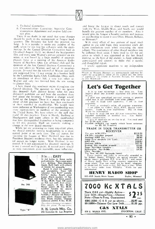
5. Technical Committee. 6. Communications Committee. Supervise Com-
munications department and propose field con- tact plan.
There is no doubt in my mind that some changes should be made in the management of League head- quarters. The Secretary has held this position too long. It is a mistake to retain any member of the staff, when he has lost his influence with the mem- bership. In the Central Division Convention held in Cleveland August 30 -31, we showed the headquarters film, and every time Warner's picture appeared on the screen it was booed by a large number of amateurs present. Later at a meeting of the Amateur Radio Society of Northern Ohio (an affiliated club and the sponsors of the last Central Division Convention) a vote was taken on Warner, and out of 44 members present, 29 voted for the removal of Warner and only one supported him, 14 not voting. In a hamfest held by the Cambridge Radio Club, Cambridge, Ohio, with an attendance of about 300, a vote was taken on Warner and only two favored him, the rest voting to dismiss him.
I have found this sentiment exists throughout the Central Division. The question is: Shall we ignore this demand? Each director knows what his own division's problems are and how the members there feel about the Secretary. I believe a change would build up the League. There is a reason why out of about 45,000 amateurs we have less than one -fourth of them enrolled in membership. We would have more influence at Washington if our membership were more representative in numbers of the amateurs in the United States. We have others on the staff that could fill this position. There is Handy, Budlong at Headquarters and many others in the membership that have distinguished themselves at being competent to fill this position. Shall we consider making a change at the next Board meeting?
While we are reviewing so many important plans, we should consider moving headquarters to a more central point at an early date. The old reason for retaining the League at West Hartford was due to President Maxim's residence there, but this sentimen- tal reason no longer exists. West Hartford is not central. It is not convenient for directors' meetings. It is not a central mailing point. A central point would be more convenient, more accessible, more influential.
No. 14A
Type "S"
It is ... EASY to cut holes in these racks and cabinets. They come apart f o r drilling. Non -chipping finish. Built light with plenty of bends for strength.
Build in steel for stability and portability. Type 14A (shown) Two 8x14" panels. 8x12 %" decks. Angle steel frame. Black crackle. 13 lbs. $4.25. Type 14A three panel, 19 lbs. $6.00. Type 14B same as 14A but with dust cover. Two panel, 19 lbs. $6.25; Three panel, 28 lbs. $8.25. Leather handle for above two models 60e extra.
Type S Cabinet (shown) - 7x10x6t,+ ". Hinged lid. Remov- able panel, chassis and bot- tom. Black crackle. Chassis cadmium plated. 6 lbs. $2.20. Dercriptire literature on request.
Ship. uets. giren. Postage extra.
R. H. Lynch Mfg. Co. 970 Camulos St. Los Angeles
and bring the League in closer touch and contact with the West, Middle -West, and South, and would benefit the greatest number of its members. Also it would give the League a broader outlook and increase its membership to move it into Ohio, Illinois, Indiana, or Missouri.6
With every effort of two persons of equal intel- ligence to use cold logic, they sometimes reach dif- ferent conclusions even when reviewing the same subject. The conclusions of other Board members may be different from mine. I have tried to fill the po- sition to which I was appointed at the last Board meeting, to the best of my ability; to keep unbiased, unprejudiced and sincere; to make this a careful and thoughtful report.
I would appreciate reactions to my independent report.
)iPoints in Western Missouri are approximately half -way be- tween the geographical center of the country and the center cf population tat present in Southern Indiana, hut moving srer.dily Westward).
Let's Get Together It is to your advantage to buy from me. Your
inquiry about any amateur apparatus will prove that to you.
I give you specialized personal service of genuine value that is not available from other jobbers.
I take in trade used apparatus. I sell on time payments.
I stock at wholesale prices all amateur apparatus. 1 ant jobber for Collins, RCA, R141E, Marine trans-
mitters. Trade in your transmitter. Buy on time. 'rite for information. 1 have in stock the new All Star transmitter kits.
Supplied assembled at nominal cost. Also Radio -
Silver transmitters. I ship all receivers on ten -day trial. You need send
but $5.00 with order. FLASH -W9ARA can supply rotary beam antennas
for 20, 10, 5 meters. TRADE IN YOUR TRANSMITTER OR
RECEIVER The new ACR -175's $119.50 PR -16's complete prepaid 95.70 National HRO Jrs 99.00 Super Pros complete (At Last) 223.44 RME -69s 118.83 National HROs 167.70 Breting 12s complete prepaid 93.00 Super Skyriders complete 79.50 Hallicraf ter Sky -Buddy 29.50 Ultra Skyrider The New NC -100 Nationals (soon)
Every inquiry and order is personally attended to by Robert Henry, W9ARA; an active amateur for eleven years; graduate E.E. from M.I.T.; and owner of Henry Radio Shop selling amateur apparatus for seven years. You can reach me by letter, telegram, or phone call 24 hours a day, 365 days a year. When in a hurry order from W9ARA. Write for any information.
HENRY RADIO SHOP 211 -215 North Main Street Butler, Missouri
7000 Kc X T A L S Thick C&S cut -Highly Active- Low
c Drift -SingleFreq. -Cleaner 7
Note -Close to Freq. Guaranteed P.P.
80M- 160M -C & S cut as above - - -_ $2.00 pp. 80- 160M- Thinner Cut Low Drift-- -__.. _11.35 pp.
C &S XTALS 836 E. WEBER AVE. STOCKTON, CALIF.
93
www.americanradiohistory.com

Osockme, Japan, April 1, 1936.
Dear Merged Editor of RADIO with - other sheets, and Sirs: -
Scratchi have take it unto himself to act as your Hon. ambassador to make attempts for merging Jap- anese and Chinese radio papers with Hon. RADIO.
I are sure that you should have Chinese and Japanese writings departments in your magazine each and every other months and at occasional intervals in be- tween, so that all of your two subscribers here in Lands of Rising Sun and Falling Daughters will make more benefits from readings from such.
Land of China are making much progress of recent dates. I are just return from trip to Hankow and I are presented with keys to city and invitations come with suddenness for Scratchi to make speeches at radio clubs. I make much success and advice of Scratchi are solicited for advisability for make take out patents on many new contraptions which Chinese hams have do/eloping. One such patent idear are shown in forthwith picture which are to be put on same page with this letter from Scratchi so people will know what I are talking about. Such picture come from currents issues of China Radio magazeen and are reprinted with permissions. It are Chinese patent applied for amazing discovery of new Han - kow Wire -Stretching Systems. As are seen from picture, radio ham simply take long piece of wire and make tie unto fire hydrunt. He then take ham- mer and knock out hole in concrete sidewalks, and
the ..MIXER MONITOR is designed for CW stations - it gives per- fect monitoring of key- ing - the output can be faded into the receiver phones at any volume level - no switching, no coil changing, no tuning - it's swell for break -in - price $9.90 net, postpaid in U. S. A. for cash. Write for further information on this versatile unit.
LAMPKIN LABORATORIES BRADENTON, FLA.
94
o Zy#)rí x
put handle stick in such hole. Sitting down please and he then pull like hell. (See picture for pulling directions.) Strong ham can thus make piece No. 12 wire look like catswitskers and save more than -10% usual somewhat discount on wire cost by stretching 25c piece of wire to very near 50c worth length.
Scratchi believe such method are patents applied for and have great merits. I take such invention home with me and try it on fire hydrunt in front of my house next door. I sit on sidewalk and pull on wire. What do you think make happen, Hon. Ed? Banzai ! ! -fire hydrunt are pulled out of hole, Scratchi pull so hard. Water shoot up in air Geysewer, and entire streets become inundated with flood. Scratchi make quick jump for nearest mountain top and send in rush call for fire department. Large fat fireman come on scene and sit on hole where hydrunt once have been, and stop up leak. He say he will make continue to sit there for 30 days at ten yen per day and force Scratchi to pay him salary for such sitting posture as good teaching lessons to tie wire unto Mt. Fujiyama next time instead of around fire hy- drunt.
It appear that, as are more usual, Scratchi are again get stung. It are timely now for Scratchi to make PS notations for explaining purposes of Chi-
New device un- scrambles the trans -oceanic telephone con- versations. A new source of entertainment for short wave fans. Hooks to audio output of any SW receiver. Circuit
diagram with instructions 50 cents -no stamps. Diagram of scrambler (Not for trans -oceanic telephone) 25c
Wireless Specialty Co. 55 OAK LANE TRENTON, NEW JERSEY
www.americanradiohistory.com

nese writings which are below picture of wire puller herewith on page. Such things say in Amer- ican language that it are advisable for ham wire stretcher to first tie ten fire hydrunts together into serious, for more safety protection against hydrunt blowup. Amount of money which can make save by such wire stretching process are colossus. I may suggest you try same some time, Hon. Editor, and I make promise you will not become patent soot litigationed by Chinese paper which give great scoop on such clever new ham money savings skeem.
I are not stretching the truth, Hon. Ed., only the wire.
I remain as I were in future, HASHAFISTI SCRATCHI.
Self Excited Oscillators [Continued from Page 2-j
A Hartley oscillator, and in fact, all oscillators should be tuned up with a d.c. milliammeter placed in the d.c. grid return for initial adjustment of excitation, as well as one placed in the d.c. plate supply lead. The grid meter indicates r.f. grid excitation, and normally
Figure 13 the d.c. grid current should approximate from 10 to 20% of the d.c. plate current (depending on the t of the tube or tubes used).
It is impossible to get much plate efficiency and output without proper grid excitation and it is lack of grid excitation that usually causes diathermy oscillators to stop oscillating, trans- mitters to become unstable, etc. The grid drive decreases as the loading of a conventional os- cillator is increased. If the loading is increased enough the grid drive drops to the point where oscillation ceases, at which time the output and efficiency drop to zero and the d.c. plate input swings up to a dangerous point. This is based
A NEW 10 -20 METER TUBE
ZT46 Outstanding features at 20M - 200 Watts Out- put at 1000V Plate Hi Mu - Low C - 15 watts for full Excitation - 50W base - Grid and Plate Terminal Caps - Chromed.
POSTCARD BRINGS MANUAL
Price $17.50 NATIONAL RADIO TUBE COMPANY 3420 18th Street San Francisco, Calif.
on the assumption that grid leak bias is the sole source of bias, and the tube is not of the "zero bias" type.
It is highly desirable, therefore, to provide a sufficient amount of grid drive in all oscillators. This improves the efficiency at maximum load, and also increases the frequency stability.
SUN SPOT DATA FROM NAA Data on solar activity are broadcast daily
from NAA, Arlington, at 2230 G.c.t. (5:30 p.m. e.s.t.). Preceded by "URSI ", sun spot data are given by the letters "SOL" followed by a five -number group. The first number is the day of the week. The second two numbers in- dicate the number of sun spot groups. The last two numbers indicate the total number of spots.
In the Heart f the Loop
SNG M `:
R0p
UP saOa h
ubd
°eh, with Both,
p^ Circulating
Ice-Water
`EpNAR o M09 n9 D
retto¡
LOW -LOSS
MICA CONDENSERS
800(/( Better Than
Bakelite
FOR DETAILS WRITE
Pat. Pend.
-1ICA DENSER
iATEIIIVENC ít Manufactured by Dumont Electric
Co., Inc 514 -516 Broadway
New York
95
www.americanradiohistory.com

Jo
ST JYIVR' ft GtJID1E. Where to Blnv It CALIFORNIA -Fresno
Ports Manufacturing Co. 3265 E. Belmont Ave. Radio W6AVV National F87 -SW3 and Parts; Hammarlund, Cardwell, Blile Crystals; Johnson Insulators Distributors RCA -DeForest Transmitting Tubes
Established 1914 Send for Wholesale Ca.alog
CALIFORNIA -Los Angeles
Radio Supply Company 912 So. Broadway
THE AMATEURS' HEADQUARTERS OF
THE WEST
All Nationally Advertised Parts for Receiving and Transmitting Carried in Stock at All
Times. 9 Licensed Amateurs on Our Staff.
CALIFORNIA -Oakland
Radio Supply Company 2085 BROADWAY
Hammarlund, Yaxley, Carter, National, John- son, IRC, Cardwell, Miller, Morrill, Flech-
theim, Triplett, Haigis Transceivers. W6GFY
CALIFORNIA -San Francisco
(hcTÉÑBA CH ELECTRIC COMPANY
1452 Market Street "The House of a Million Radio Paru"
Hammarlund and National sets and parts RCA and EIMAC Tubes.
Arcturus Receiving Tubes. Trimm Phones, all types.
Johnson Antenna Feeders, Insulators, Transposition Blocks.
ILLINOIS -Chicago
CHICAGO RADIO APPARATUS CO., Inc.
Established 1921
415 SOUTH DEARBORN STREET (Near Van Buren Street)
ALL SUPPLIES FOR THE SHORT WAVE FAN AND RADIO AMATEUR
QUOTATIONS FREELY GIVEN ON
ANY KIT OR LAYOUT
Short Wave Receivers Taken in Trade Get our low prices
PARTS REQUIRED FOR BUILDING
EQUIPMENT SHOWN IN THIS
ISSUE
The parts listed are the components of the mod- els built by the author or by "Radio's" Laboratory staff. Other parts of equal m e r it and equivalent electrical characteristics may usually be substitut- ed without materially af-
fecting the performance of the unit.
The "Traffic Ten" Receiver
Cs- Hammarlund MC- 35-8
C2, Cs- Cardwell "Trim Air" 75 p cfd.
C +- National SF -150 (rebuilt)
Ca- National SF.- 150
Cs- Cardwell "Trim Air" (rebuilt as described in text)
Ca- Hammarlund MEX -50
RFCI- National 100
RFC2- Miller 16 -MH (shielded)
RFCa- Hammarlund CH -10 -S
Switch -Yaxley, 2 gang, 4 point
IFTi- Hammarlund ATT -465
IFTs- Hammarlund T- 465 -CT
IFTen- Hammarlund ATO -465
Power trans. -Metal Products type 6230
Dials -"K -K" 4 inch Unmarked Condensers -
Aerovox type 1450
CHICAGO -Illinois
Mid -West Radio Mart 520 South State Street
Rex L. Munger, W9LIP, Manager America's Amateur Headquarters
ILLINOIS -Chicago
NEWARK ELECTRIC CO. 226 WEST MADISON STREET
The Best at Lowest Prices -Write for
Complete Catalog
NEW MEXICO -Albuquerque
WM. H. ALLEN CO. BOX 641
DISTRIBUTORS OF NATIONALLY ADVERTISED RADIO
NEW YORK, N. Y. 227 FULTON ST.
411/4 / CC.
Complete Stock of Amateur Radio Supplies at Wholesale Discounts
PENNSYLVANIA-Philadelphia
M & H Sporting Goods Company
512 Market Street
PENNSYLVANIA -Pittsburgh
CAMERADIO COMPANY 603 GRANT STREET
WASHINGTON- Spokane
Spokane Radio Co., Inc.
611 First Avenue
96
www.americanradiohistory.com

The Marketplace (a) Commercial rate: 10c per word, cash with order:
minimum. $1.00. Capitals: 13c per word. For consecu- tive advertising, l5";, discount for 3rd. 4th. and 5th insertions; 25"'n thereafter. Break in continuity re- stores lull rate. Copy may be changed often as de- sired.
(b) Non -commercial rate: 5c per word, cash with order: minimum. 50e. Available only to licensed am- ateurs not trading for profit: our judgment as to character of advertisement must be accepted as final.
(c) Closing date (for classified forms only): 25th of month; e.g., forms for March issue, published in February, close January 25th.
(d) No display permitted except capitals. (e) Used, reclaimed, defective, surplus, and like
material must be so described. (f) Ads not relating to radio or radiomen are ac-
ceptable but will be grouped separately. (g) No commissions nor further discounts allowed.
No proofs, free copies. nor reprints sent. (h) Send all Marketplace ads direct to Los Angeles
accompanied by remittance in full payable to the order of Radio, Ltd.
(i) We reserve the right to reject part or all of any ad without assigning reasons therefore. Rates and conditions are subject to change without notice.
CRYSTALS -80 and Inn meter hands 95c. A stock of 1,000 crystals insures you prompt delivery. New type shielded hold- er 60,.. Fits standard five prong socket. White Radio Lab- oratory, Sandpoint, Idaho.
COI.LECTOR trades radio parts, engineering counsel, mechanical, electrical, stamps; build xmitting equipment for violins, violas, violincellos, bows any condition. W2FED.
\\'9SQB may write for free Handbook.
SPECIAL "ultra -de -luxe" copies of the 1936 "RADIO HAND- BOOK '', hound with Vellum Cloth. front cover and back- bone stamper in imitation gold. These "ultra -de -luxe" hand- books are printed on heavy, coated enameled paper, hound like a regul ir text hook. A magnificent job. Price $2.50, prepaid. Pacific Radio Publishing Co., Pacific Bldg., San Francisco, Cal.
A (ree Handbook to W5MX.
GUARANTEED TRANSFORMERS and chokes. Power supplies, modulation equipment, microphones, amplifiers, preamplifiers, etc. Universal class B transformers, 100 watts- pair $8.00. Racks and panels, all sizes. Amperes tubes. I.angrick Radio Engineering Service. WEPT, 626 Maltman Avenue, Los Angeles.
FOR SALE: One Westinghouse 500 volt d.c. motor generator set in good condition, $18.00. Motor is 110 volts a.c. W9CDE.
One Handbook free to WIAKF.
SEI.L: R32's, I Kw. Transformer, Crystals, Holders, Old UV202's, SO watter, Generator. 300 miscellaneous parts. Illustrated list. Lane Jackson, Independence, Missouri.
One Handbook free to W6KYG.
SELLING OUT: Transmitting tubes, transformers, I0t00 v. Edison "B ", mounted crystals, holders, blanks. SW3. 300 Miscel- laneous parts. Illustrated list. I.ane Jackson, Independence, Mo.
TRANSFORMERS REWOUND and built to specifications. Very best quality materials and workmanship. Scuff Transformer Co., 1929 Forest Ave.. St. Louis.
\ä'7APH may write for free Handbook.
RELAY rack 30 watt eon:rnlied earner phone, 120 watt c.w.set. Uses pair of RK2O's in final amplifier driven by two 53's. Complete with 80 meter roils, built -in power supply, tubes, and $SO broadcast type carbon mike. Sell for 5145, Frank C. Jones. 203- Durant Ave., Berkeley, Calif.
SPFCIAI. R66B's- $3,75. 866.s-- $1.6S. Guaranteed six months. F. B. Condenser mike heads $10.00. loo watt Universal Class "B" transformers $8.00 pair. Langrick Radio Engineering Service. W6PT. 626 Maltman Ave., Los Angeles, Calif.
SELL -New Sr. Speed -ex key guaranteed. $6.00. W7FFJ.
WE build most any size steel cabinet to house that gadget you are building. R. H. I.ynch, 9-0 Camulos, Los Angeles.
RACKS, cabinets, shield cans. Send for circulars. R. H. Lynch. 970 Camulos, Los Angeles, Calif.
A free Handbook to W9LNO.
RAW QUARTZ - -finest quality, for the manufacture of piezo crystals. Largest. most complete and varied stock in America. Brazilian Importing Co., Inc., 6 Murray St., New York City.
TRANSCEIVER cabinets. Send sketch for price on size you want. R. H. Lynch, 9-0 Camulos, Los Angeles.
SELL McMurdo Silver fifteen tube Masterpiece receiver, Sampson two fifty amplifier. Glenn Watt, Chanute, Kans.
CUSTOM -BUILT TRANSFORMERS, chokes -power and audio. Our reputation assures quality. May we quote? Baker Engin- eering. Fort Wayne, Indiana.
DANGER! High voltage card (red and blue), 10c; CALL - BOOKS, $1.25. Bliley 14 mc. crystal, $7.50. WADED, Holland, Mich.
WANTED. Old radio sets or parts for ham antique collection. All letters answered. W6LM.
QSL SWL Cards, neat, attractive, reasonable. Samples (ree. Miller. Printer, Ambler, Pa.
SUPER -SIGNAL, the new crystal supreme, $5.00. Information on request. Also V, AT. and X at popular prices. WIBD.
To W3BAS a free Handbook.
QSL's, 300 one -color cards $1.011. Samples. 21.13 Indiana Avenue, Columbus, Ohio.
CRYSTALS and blanks. X or Y cut; 1750 to 2000; 3500 to 41100; close to your specified frequency $1.33, Blanks, unfin- ished hoc. Bill Threm, WAFN, 4021 Davis Ave.. Cheviot, Ohio.
POWERFUL "T -9" dependable X cut 40 meter crystals: $1.50 within 10 kilocycles, $2.00 within S kilocycles, $2.50 for exact frequency-postpaid ; also 80's same prices. Written guarantee, calibration card and instructions with every crystal -you must be pleased. Mention ad. "Eidson's ', Temple, Texas.
WANTED -Used Collins Pone transmitter, 100 watts or less. State all details. WSPNF.
GENERAL ELECTRIC dynamorors 24/750 volts, 200 mils., $25.00. Two for 1500 volts $40.00. Westinghouse 27/350 $10.00. 500 Watt. 500 cycles, 510.00. list. Harry Kienzle, 215 Hart Blvd., Staten Island, New York.
TRANSFORMERS, chokes, all types. Reasonable. Guaranteed. Special universal class B inputs and outputs 100 watts audio - pair $8.00. California Radio Labs.. W6CYQ, 2523 South Hill Street, Los Angeles.
Ti, WRCRZ a free Handbook.
FINE QSL's' SWL's! Samples. W9UII Press, 2009 Fremont Street, Chicago.
QSL's, 300 one -color cards $1.00. Samples. 2143 Indiana Avenue. Columbus, Ohio.
NATIONAL AGSX receiver. Full set A, B. C. D, and E coils. Rack mounting, power supply, permanent magnet speaker. $95 f.o.b. Remler condenser microphone, special "bomb" amplifier. A beauty, perfect condition. $35.00. W6APU, 428 No. Maple Drive. Beverly Hills, Calif.
NEON TUBES, four inches, for RF testing, Oscilloscopes, special lengths made to order. Postpaid (U. S., Canada ) $3.00. WSAXB, GLOMU SPECIALTIES, 3411 Harrison Avenue, Cheviot, Ohio, Dept. B.
CRYSTALS -40 meter hand X cut $1.85. Guaranteed satisfac- tion or money hack. 80 -160 hands $1.50. Omaha Xtal Labs., 501 World Herald Bldg., Omaha, Nebr.
WANTED: Edison storage "A" batteries, UX852s. Grote Reber, Wheaton, Illinois.
LARGE STOCK new and used equipment for sale by .'southern Ohio's only amateur owned amateur business -Jos. N. Davies, Box 602, R.R. 9, North Bend Rd., Mt. Airy, Cincinna:i, Ohio.
P() \ \'I.R Supply I100V -130 ma.; 500V -8S ma.: 7;;V -3A; LOA: SV -3A; Fil. C.T., 522.50. 5 Metet receiver
$12.93, 10M Converter 510.95, Transformer manufacturers to specifications. All equipment completely built. Write for furthet information. Precision Radio Laboratories, 109 E. 94 St., Brooklyn, N.Y.
COMPLETI! VOLUME "RADIO" 1935. 12 issues. Not many of these left. Better order now. $3.110 for the entire year's volume. Order from Pacific Radium Publishing Co.. Inc., Box 3278, San Francisco, U.S.A.
CRYSTALS: SATISFACTION OR MONEY BACK. I. 0-80 meters within 10 kilocycles Y-ait $1. X -cut $1.33. W ight Laboratory, 5859 Glenwood, Chicago, Ill.
WE have our PR -16 and can make deliveries. Used sets and parts. List Free. W9OC, Spencer, Iowa.
97
www.americanradiohistory.com

O 0 0
Radio /raÍ'%uL ,t(11.:.%-iJr again,
o Q
when all other means of communication in the recently flooded areas failed . .
DR. J. P. VANCHERI AND HIS APPARATUS
;ÿ t
"My transmitter was on the air 86 out of 96 hours . . . I had some difficulties, but not with the speech equipment, thank goodness. The entire speech equipment from microphone to Class B input is LS- U.T.C.... only the output transformer is a 'home cooked' job, designed and built at the University of Purdue.
"Am a 'crank' on good quality. Have a B.F. Oscillator and Oscilloscope and have made frequent tests of all makes of
transformers and there is no comparison when stacked up against U.T.C.... "'
DR. JOSEPH P. VANCHERI W8BV'IH
UNSOLICITED
Exclusive U.T.C. Distributors carrying a complete stock of U.T.C. Products
Harvey's Radio 105 W. 43rd St., New York. N. Y.
Goldhamer's, Inc. 610 Huron Road, Cleveland. Ohio
Wholesale Radio Service Co 100 Sixth Avenue, New York. N. Y.
Wholesale Radio Service Co... 219 Central Ave., Newark, N. J.
Wholesale Radio Service Co..430 W. Peachtree St., N.W., Atlanta, Ga.
Wholesale Radio Service Co 911 Jackson Blvd., Chicago, Ill.
Wholesale Radio Serv;c: C... _ ..54227 East s Fordham Nd., Boon%
Sun Red N.
Redo Y.
Gross Radio, Inc. 51 Vesey St., New York, N. Y.
Leeds 45 Vesey St., New York. N. Y.
Mohawk Electric Co.... .....1335 State St., Schenectady, N. Y.
Walter Ashe 1100 Pine St., St. Louis, Mo.
Radio Shack 46 Brattle St., Boston, Mass.
Hatry and Young New Haven and Hartford, Conn.
Maine Radio Co 124-13 101st Ave., Richmond Hill, N. Y.
Filet et Radio 5 Rue Denis Poisson, Paris, France
Hall's 35 So. Cameron, Harrisburgh, Pa.
Herbach & Rademan 438 Market St., Philadelphia, Pa.
Radio Electric Service 7th and Arch Sts., Philadelphia, Pa.
Cameradio Company 603 Grant St., Pittsburgh, Pa.
W. H. Edwards & Co 32 Broadway, Providence, R. I.
Seattle Radio Supply, Inc 2319 Second Ave., Seattle, Wash.
San Francisco Radio Exchange . . 1284 Market St., San Fran., Calif.
Straus Frank Co. San Antonio, Texas
Straus Frank Co Houston, Texas
Rissi Brothers 5027 Hamilton Ave., Detroit, Mich.
Amateur Radio Equipment. 138 East Butler Ave., Memphis, Tenn.
Northeastern Radio 281 Columbus Ave., Boston, Mass.
Springfield Radio 397 Dwight St., Springfield, Mass.
Kraus & Co 89 Broadway, Providence, R. I.
Braid Electric Co 107 Ninth Ave., Nashville, Tenn.
Wisconsin Radio Supply 434 W. 8th St., Milwaukee, Wis.
Bruce Company 206 E. Monroe, Springfield, Ill. Beaucaire Company 228 Broadway, Rochester, N. Y.
Dallas Electric Supply Co. Dallas, Texas
Peterson Lumber & Supply Co. El Paso, Texas
South West Radio Supply Co...107 South St. Paul St , Dallas, Texas
SOUTHERN CALIFORNIA
Pacific Radio Exchange, Inc 729 S. Main St., Los Angeles
Radio Supply Co. 912 S. Broadway, Los Angeles
Radio Television Supply Co 1701 S. Grand Ave., Los Angeles
Radio Specialties Co 1816 W. 8th St., Los Angeles
Zack Radio Co. .......1000 S. Broadway, Los Angeles
www.americanradiohistory.com

1
- -- - 50 CW RF UNIT
Consists of Crystal- controlled pentode oscillator, pentode buffer - doubler, push pull final amplifier and choke input mercury vapor rectifier system having a regulation better than 5 %, readings on 5 circuits instantaneously through one meter. Used by itself this unit is a highly efficient 50 watt CW transmitter. 50 CW RF unit completely mounted ready to wire with one set of coils (specify band desired) including dust cover, less tubes and crystal. Tubes required: 2- 2A5's, 2 -46's, 1 -83. Net to hams $68.40
Extra set of coils (either for 20, 40, 80 or 160 meters), Net to hams $4.80
30 AF MODULATOR ASSEMBLY
Consists of a high gain speech amplifier and Class B modulating stage. It has an output of 30 watts, and when used to modulate the RF amplifier at 100°ó modulation the distortion level is less than 5 %. This amplifier is designed for use with high level crystal microphones and will operate with any of the carbon type. 30 AF Modulator assembly completely mounted, ready to wire, including dust cover but less tubes. Tubes required:-2-57's, 3 -46's, 1 -83. Net to hams $39.60
50 CC VARIACTOR CARRIER CONTROL Hos a separate power supply for 50 watt class C stage and
Variactor units for carrier control. Instantaneous switchover provid- ed from carrier control to constant carrier. When used with 500 watt class B Linear stage DX coverage is increased, efficiency of the Linear stage is easily doubled. Reduces interference between stations tremendously. 50 CC Variactor Carrier Control unit com- pletely mounted, ready to wire with dust cover, less tube. Tube re- quired: 1 -83. Net to hams $33.60
Full Scale Working Print Brochure covering all construc- tional plans for the 50 watt, 500 watt and 750 watt units may be purchased from your distributor or direct for 25c. Free with purchase of each sectional unit. :COMPLETE ASSEMBLY OF THE THREE UNITS
VOA, can win this Transmitter Phone - CW Kit Fully
The 50 watt variactor controlled carrier kit shown will be given FREE to the amateur who suggests a name that will best describe this series of kits. Contest closes July 1st, 1936. Judges are L. M. Cockaday and Frank Jones, two nationally known radio editors. Mail suggested names direct to UTC.
While priced within the reach of every amateur, these variactor
.
mounted, ready -to -wire controlled carrier kits represent the finest in transmitter design. The conservatively rated components come from the finest manu- facturers in radio: UTC, Cardwell, Cornell Dubilier, Hammarlund, Isolantite, Aerovox, IRC, Triplett, Yaxley., Johnson, Electrad, etc.
Tubes by RCA. These units are furnished completely mounted in rack panel construction, with etched metal overlay plates.
MAIL ONLY 25C FOR THE FOLLOWING THE NEW UTC CIRCULAR SLIDE RULE The most useful instrument a radio engineer
could have. Here ore some of the electrical and mathematical problems to which it gives direct answers: Multiplication . . . Division . . . Propor- tion . . . Reciprocals . Squares Square Roots ... Voltage Drop in Resistors . . . Wattage in o Resistor for Given Voltage or Current . . .
Impedance of an Inductance at Any Frequency ... Impedance of a Condenser at Any Frequency . . .
Resonance Calculations . . . Effective Capacity of Condensers in Series . . . Effective Resistance of Resistors in Parallel . Calculation of Bias Resistors . Power Level Conversion to DB .
Voltage or Current Ratio Conversion to DB Gain ... Sound and Light Calculations . Cir- cumference and Area of Circles . Stroboscope for Checking 33 -1/3 or 78 RPM Turn -tables. Due to its 16 inch effective length, the accuracy of this
rule is greater thon many of the standard rules selling at 30 times its price.
NEW TRANSMITTER BULLETIN Covering circuits and laboratory built transmis -
tors from 5 watts to 1,000 watts output.
ALL LABORATORY CIRCUITS As they are released over a period of one year
covering new amplifiers and variactor controlled carrier RF transmitters.
NEW 48 PAGE TECHNICAL BULLETIN which includes dota and circuits on amplifiers from one half watt to 1,000 watts output, chapters on audio transformer design, application of power transformers and filters, also charts on decibel con- version in terms of watts and conversion of power or voltage ratios to DB, reactance data, filter ripple calculations, etc.
V U222L) r a,Augyoab a'a V ©aiQ 72 SPRING STREET NEW YÖRK, N. Y.
EXPORT DIVISION - 15 LAIGHT STREET, NEW YORK. N. Y.
www.americanradiohistory.com

DOWN GO PRICES
AS
POPULARITY GOES UP!
COMPARE these prices - see your savings on
these famous types, each one
of which now is available
to you for less than ever be-
:ore. At these new low prices
you cannot afford to be with-
out the assurance of reliable
rube performance RCA gives
you. Take advantage of these
new prices and use RCA
tubes in your transmitter.
RCA-. 203 -A formerly $17.50. NOW
RCA - 211 formerly $17.50. NOW
RCA -845 formerly $20.00. NOW
RCA - 838 formerly $18.00. NOW
RCA - 860 formerly $35.00. NOW
RCA- 866 -A formerly $5.00. NOW
RCA - 868 formerly $6.00. NOW
RCA - 918 formerly $6.00. NOW
$15.00 '15.00 16.00 $16.00 532.50 b4.00 55.00 $5.00
AMATEUR RADIO SECTION
RCA Manufacturing Co., Inc., Camden, N. J. A SERVICE OF THE RADIO CORPORATION OF AMERICA
www.americanradiohistory.com