309115C GTS ProCart HVLP Compressor/Cart - · PDF fileGeneral Information HVLP Compressor/Cart...
18
309115 Rev. C First choice when quality counts.t 7930A turbine spray gun not included INSTRUCTIONS–PARTS LIST INSTRUCTIONS This manual contains important warnings and information. READ AND KEEP FOR REFERENCE. GTS-ProCart t HVLP Compressor/Cart 240V AC 50/60 Hz Model 233059, Series A Cart with compressor, 2 1 / 2 -gallon remote pressure pot, and material and air hoses 15 psi (104 kPa, 1.0 bar) Maximum Working Pressure Related Manuals HVLP Turbine Sprayers 308832 . . . . . . . . . . . . . . . . . . . GTS-960 Bleeder Gun 308336 . . . . . . . . . . . . . . . . . . . . GTS-980 Non-Bleeder Gun 308810 . . . . . . . . . . . . . . . . GRACO INC. P.O. BOX 1441 MINNEAPOLIS, MN 55440–1441 ECOPYRIGHT 2000, GRACO INC. Graco Inc. is registered to I.S. EN ISO 9001
-
Upload
nguyenthien -
Category
Documents
-
view
224 -
download
1
Transcript of 309115C GTS ProCart HVLP Compressor/Cart - · PDF fileGeneral Information HVLP Compressor/Cart...

309115Rev. C
First choice whenquality counts.�
7930Aturbine spray gunnot included
INSTRUCTIONS–PARTS LIST
INSTRUCTIONS
This manual contains importantwarnings and information.READ AND KEEP FOR REFERENCE.
GTS-ProCart�
HVLP Compressor/Cart240V AC 50/60 Hz
Model 233059, Series ACart with compressor, 21/2-gallon remote pressure pot,and material and air hoses
15 psi (104 kPa, 1.0 bar) Maximum Working Pressure
Related ManualsHVLP Turbine Sprayers 308832. . . . . . . . . . . . . . . . . . . GTS-960 Bleeder Gun 308336. . . . . . . . . . . . . . . . . . . . GTS-980 Non-Bleeder Gun 308810. . . . . . . . . . . . . . . .
GRACO INC. P.O. BOX 1441 MINNEAPOLIS, MN 55440–1441�COPYRIGHT 2000, GRACO INC.
Graco Inc. is registered to I.S. EN ISO 9001

���������������
Table of ContentsWarnings 2. . . . . . . . . . . . . . . . . . . . . . . . . . . . . . . . . . . . . General Information 4. . . . . . . . . . . . . . . . . . . . . . . . . . . . Component Identification and Function 5. . . . . . . . . . . . Setup 6. . . . . . . . . . . . . . . . . . . . . . . . . . . . . . . . . . . . . . . . . Shutdown 11. . . . . . . . . . . . . . . . . . . . . . . . . . . . . . . . . . . . Maintenance 12. . . . . . . . . . . . . . . . . . . . . . . . . . . . . . . . . . Troubleshooting 13. . . . . . . . . . . . . . . . . . . . . . . . . . . . . . . Repair 14. . . . . . . . . . . . . . . . . . . . . . . . . . . . . . . . . . . . . . . Accessories 15. . . . . . . . . . . . . . . . . . . . . . . . . . . . . . . . . . Parts Drawing 16. . . . . . . . . . . . . . . . . . . . . . . . . . . . . . . . . Parts List 17. . . . . . . . . . . . . . . . . . . . . . . . . . . . . . . . . . . . . Specifications 17. . . . . . . . . . . . . . . . . . . . . . . . . . . . . . . . . Graco Standard Warranty 18. . . . . . . . . . . . . . . . . . . . . . Graco Phone Number 18. . . . . . . . . . . . . . . . . . . . . . . . . .
SymbolsWarning Symbol
WARNINGThis symbol alerts you to the possibility of seriousinjury or death if you do not follow the instructions.
Caution Symbol
CAUTIONThis symbol alerts you to the possibility of damage toor destruction of equipment if you do not follow theinstructions.
WARNINGFIRE AND EXPLOSION HAZARD
Improper grounding, poor ventilation, open flames or sparks can cause a hazardous condition andresult in a fire or explosion and serious injury.
� Ground the equipment and the object being sprayed. See Grounding on page 6.
� If there is any static sparking or you feel an electric shock while using this equipment, stopspraying immediately. Do not use the equipment until you identify and correct the problem.
� Provide fresh air ventilation to avoid the buildup of flammable fumes from solvents or the fluidbeing sprayed.
� When flammable liquid is sprayed or used for flushing or cleaning the equipment, the compressormust be placed at least 20 feet (6.1 m) away from areas where hazardous concentrations offlammable vapors are likely to occur.
� Use additional air hose if necessary to ensure that the compressor is operated in a clean, dry,well-ventilated area.
� Never place the compressor inside a spray booth! Use this equipment outdoors or in extremelywell-ventilated areas.
� Keep the spray area free of debris, including solvent, rags, and gasoline.
� Electrically disconnect all equipment in the spray area.
� Extinguish all open flames or pilot lights in the spray area.
� Do not smoke in the spray area.
� Do not turn on or off any light switch in the spray area while operating or if fumes are present.
� Do not operate a gasoline engine in the spray area.

���������������
WARNING
INSTRUCTIONS
EQUIPMENT MISUSE HAZARD
Equipment misuse can cause the equipment to rupture or malfunction and result in serious injury.
� This equipment is for professional use only.
� Read all instruction manuals, tags, and labels before you operate this equipment.
� Use the equipment only for its intended purpose. If you are not sure, call your Graco distributor.
� Do not alter or modify this equipment. Use only genuine Graco parts.
� Check equipment daily. Repair or replace worn or damaged parts immediately.
� Do not exceed the maximum working pressure of the lowest rated system component. Thecompressor/cart has a maximum working pressure of 15 psi (104 kPa, 1.0 bar).
� Use fluids and solvents that are compatible with the equipment wetted parts. See Specificationson page 17 for wetted parts.
� Do not use hoses to pull equipment.
� Route hoses away from traffic areas, sharp edges, moving parts, and hot surfaces. Do not exposeGraco hoses to temperatures above 82�C (180�F) or below –40�C (–40�F).
� Wear hearing protection when operating this equipment.
� Do not lift pressurized equipment.
� Comply with all applicable local, state, and national fire, electrical, and safety regulations.
� Do not point the gun at anyone or at any part of the body.
� Do not put your hand or fingers over the gun fluid nozzle.
� Do not stop or deflect leaks with your hand, body, glove or rag.
� Do not “blow back” fluid; this is not an air spray system.
� Follow the Pressure Relief Procedure on page 11 if the fluid nozzle clogs and before you clean,check, or service this equipment.
� Tighten all fluid connections before you operate this equipment.
� Check the hoses, tubes, and couplings daily. Replace worn or damaged parts immediately.
TOXIC FLUID HAZARD
Hazardous fluid or toxic fumes can cause serious injury or death if splashed in the eyes or on the skin,inhaled, or swallowed.
� Know the specific hazards of the fluid you are using.
� Store hazardous fluid in an approved container. Dispose of hazardous fluid according to all local,state, and national guidelines.
� Always wear protective eyewear, gloves, clothing, and respirator as recommended by the fluid andsolvent manufacturer.
� Do not use 1,1,1-trichloroethane, methylene chloride, other halogenated hydrocarbon solvents orfluids containing such solvents in the turbine spray system, which contains aluminum and/orgalvanized-coated parts. Such use could result in a serious chemical reaction, with the possibilityof explosion, which could cause death, serious injury, and/or substantial property damage.

���������������
General InformationHVLP Compressor/Cart Information
The GTS-ProCart HVLP Compressor/Cart provides airpressure to a 21/2-gallon remote pressure pot or to a2-quart remote pressure pot. Fluid under pressure ispropelled from the pressure pot to the turbine spraygun.
HVLP System Operation
The GTS-ProCart HVLP Compressor/Cart, turbinesprayer, and turbine spray gun comprises the HVLPsystem. The HVLP system can spray most coatings orfinishes currently being used for automotive refinish,industrial, aerospace, marine, wood, plastic, andarchitectural applications.
The spray gun of the HVLP system utilizes inbound airpressure from the compressor/cart and HVLP turbinesprayer to produce a high-quality paint finish. Thespray gun produces a cone of air that carries anddirects paint from the gun to the surface with minimumoverspray. Application is easy, because only a fewpasses are required to obtain coverage. Increasedsystem transfer efficiency reduces materialrequirements and clean-up time. The system complieswith clean air laws for reduced volatile organiccompounds (VOC) emissions.
See HVLP Turbine Sprayers manual 308832 forinformation on the operation and use of the HVLPturbine sprayer. See Turbine Gun manual 308336 or308810 for information on operating the turbine spraygun.
Various configurations of HVLP compressor/carts,turbine sprayers, guns, and accessories are availableto meet specific application requirements.
Unpacking
Unpack the compressor/cart from the shipping carton,and inspect for any possible shipping damage. Ifanything is damaged, call your distributor.
The contents of the GTS-ProCart HVLPCompressor/Cart are as follows:
� 233059: cart with compressor
� 240476: material hose
� 240059: air hose
� This instruction manual

���������������
Component Identification and Function
7930A
Fig. 1
E
C
B
G
D
A
F
H
J
K
A Remote pressure pot holder Provides space for 2-quart or 21/2-gallon pressure pots
B Air outlet Connection for compressor air supply to remote pressure pots
C Turbine latch Locks turbine sprayer in position on cart
D Hose holder Provides storage space for sprayer hose, gun, and accessories
E Compressor/Cart handle Folds flat for minimum storage space
F Turbine sprayer base mount Provides lock-mount for turbine sprayer on cart
G ON/OFF switch Power switch for compressor motor
H Air and material hoses Provide operating air and material to gun
J 21/2-gallon remote pressure pot Holds 21/2 gallons of application material
K Turbine spray gun (not included) Applies and controls flow of material to be sprayed

��������������
SetupGrounding
WARNINGImproper installation or alteration of the groundingplug will result in a risk of electric shock, fire orexplosion that could cause serious injury or death.
� This equipment requires a 240V AC, 50/60 Hz, 8Acircuit with a grounding receptacle. See Fig. 2.
� Extension cord must be 3-wire,1.5 mm2, no longerthan 15 m.
Fig. 2grounded outlet
Setup/Use Options
The HVLP compressor/cart has a variety of useroptions. See Fig. 3.
NOTES:
� See Turbine Sprayer manual 308832 forinformation on turbine setup and operation.
� See Turbine Gun manual 308336 or 308810 forinformation on turbine spray gun setup andoperation.
Prepare the Fluid
� Always strain the fluid before spraying; this includescolor, reducer, and hardeners if used.
� When using a turbine spray system, use aslower-drying reducer or thinner to compensate forthe faster drying time caused by the warm air of theturbine. Do not over reduce.
CAUTIONThe performance of the turbine sprayer varies withthe viscosity of the material and the length of thehose. Keep the hose short to prevent pressure drop.
Paint Reduction — Automotive Type Finishes
Reduce and catalyze all paint to manufacturer’sspecifications. To compensate for the faster dryingtime of turbine systems, use a reducer that is one stepslower than what is used for conventional air spray.
Paint Reduction — Industrial or DomesticCoatings
Reduce and catalyze all paint to manufacturer’sspecifications. If no reductions are given, firstthoroughly mix the fluid to be sprayed, then graduallymix in the proper reducer. Test the fluid until you havethe correct spraying consistency.
To test the consistency, remove the stir stick from thethinned paint. When the paint stream running off thestir stick breaks into droplets, the first few drops shouldbe about one second apart.

��������������
Setup
TI0099A
7931A
Fig. 3
Compressor/Cart with 21/2-gallonremote pressure pot
turbine sprayer
Storage Position for Cart Handle1. Turn knob to free handle.2. Fold handle down to store.
Turbine Sprayer1. Place turbine sprayer on cart.2. Move latch on cart to the right to lock turbine sprayer.3. Plug compressor/cart power cord into auxiliary
electrical outlet on turbine sprayer or into a separategrounded electrical outlet.
4. Plug turbine sprayer into grounded electrical outlet.
NOTE: Extension cord must be 3-wire,1.5 mm2, nolonger than 15 m.
Remote Pressure Pot1. Place remote pressure pot in
pressure pot holder on cart.2. Follow Connect Fluid and Air
Supply instructions on page 8.
turbine sprayer
(see manual 308832)
latchauxiliary electrical outlet
remotepressure
pot
cart
knobTI0105

Fig. 4
C
D
21/2-gallon remote pressure pot2-quart remote pressure pot
F
J
J
A
G
G
G
C
A
B
L
E
cup setup for spray gun
E
H
H
Dcup-over option
(see manual 308336 or 308810)
F
K
K
7934A
GTS-ProCart HVLP Compressor/Cart
A
remote pressure potsetup for spray gun
���������������
SetupConnect Fluid and Air SupplySee Fig. 4
� The HVLP compressor/cart provides the air supplyfor remote pressure pots.
� The circled letters in Fig. 4 indicate hose lineconnections.
1. Connect gun air supply hose (A) between turbineair outlet (B) and gun air inlet (C). DO NOT usewrench to tighten connections; hand tighten only.
NOTE: The GTS-4900 turbine uses a quickconnector at the air outlet (B). A wrench is notrequired to connect the air hose (A).
2. If using spray gun cup (D):Connect cup to gun fluid inlet (E).
If using accessory remote pressure pot (F):Connect fluid supply hose (G) between remotepressure pot fluid outlet (H) and gun fluid inlet (E).Connect pressure pot air hose (J) betweenpressure pot air regulator inlet (K) and cartcompressor air outlet (L).
Connect to Electric Supply
See Turbine Sprayer in Fig. 3 on page 7.

���������������
SetupFill the Cup or Remote Pressure Pot
Spray Gun Cup
WARNINGThe spray gun cup is pressurized by the gun’s airsupply. To reduce the risk of serious injury frompressurized fluid or accidental spray from the gun,always turn off the air supply to the gun before youremove the spray gun cup.
Only fill the cup 3/4 full to help keep the air pressuretube clean, then install the cover. The under-cup coverhas a latch (H) to secure it to the cup. The over-cuphas a ring with notches (J) that secures the cup hoodinto place when locked in place on the cup.
Fig. 5 �����
HJ
�����
Accessory Remote Pressure Pot
WARNINGAccessory remote pressure pots remainpressurized until pressure is manually relieved. Toreduce the risk of serious injury from pressurizedfluid or accidental spray from the gun, alwaysrelieve pressure in the pressure pot before youloosen or remove the cover.
1. Relieve remote pot pressure as follows:
a. Turn off air supply to pressure pot. See Fig. 6.
b. 21/2-gallon remote pressure pot:Pull pressure relief valve ring (206c) untilpressure is completely relieved.
2-quart remote pressure pot: Turn out pressure relief knob (113) one turn.Wait until pressure is completely relievedbefore you remove cover. Close knob.
Fig. 6
206c
�����
113
�����
2 quart21/2 gallon
2. Remove pressure pot cover, and fill. Secure cover.
NOTE: 2-quart remote pressure pot only: Lightly coat the cover threads with petroleum jelly.
CAUTIONIf the 2-quart remote pressure pot is accidentallytipped over or held at too great of an angle, fluid mayleak into the air regulator and cause damage. Takeprecautions to avoid this. If fluid does get into theregulator, clean it immediately.
CAUTIONDo not tighten the pressure pot cover more thanhand-tight. Excessive tightening may damage thecover gasket.

����������������
SetupPrepare the Surface to be Sprayed
To achieve proper adhesion, make sure the surface tobe sprayed is completely clean.
Operating the Compressor
WARNINGSparking can be expected in the normal operationof the motor. Sparks could ignite fumes fromflammable liquid, dust particles, and otherflammable substances in the spray area and causeserious injury and property damage.
Follow the precautions below:
� When flammable liquid is sprayed or used forflushing or cleaning equipment, the compressormust be placed at least 20 feet (6.1 m) awayfrom areas where hazardous concentrations offlammable vapors are likely to occur.
� Use additional air hose if necessary to ensurethat the compressor is operated in a clean, dry,well-ventilated area.
� Never place the compressor inside a spraybooth! Use this equipment outdoors or inextremely well-ventilated areas.
� Avoid all ignition sources such as staticelectricity from plastic drop cloths, open flamessuch as pilot lights, hot objects such ascigarettes, and arcs from connecting ordisconnecting power cords or from turning lightswitches on and off. Extinguish or remove allsources of ignition.
1. Turn the compressor on a few minutes before youstart spraying to allow warm-up time.
NOTE: When the compressor is not in use for anextended period of time, turn it off. Thecompressor does not shut off automatically.
2. Be sure the compressor filter is clean beforeoperating. See page 12 for instructions onchecking and cleaning the filter.
NOTE: To adjust the spray pattern, see turbine gunmanual 308336.
Cold Weather Operation
The HVLP compressor/cart uses a diaphragmcompressor. A new diaphragm may be stiff in coldweather. If cold enough, the diaphragm is too stiff toallow the compressor motor to start (the unit hums).If this occurs, follow these steps:
1. Turn turbine and compressor OFF.
2. Unplug turbine from power source.
3. Remove filter. Clean or replace if dirty.
4. Spin cooling fan on compressor for a fewrevolutions.
5. Reassemble filter.
6. Plug in turbine.
7. Turn turbine and compressor ON. Repeatprocedure if necessary.
����������������
ShutdownPressure Relief Procedure
WARNINGPRESSURIZED EQUIPMENT HAZARD
The equipment stays pressurized until pressure ismanually relieved. To reduce the risk of a seriousinjury from pressurized fluid, accidental spray fromthe gun, or splashing fluid, follow the PressureRelief Procedure whenever you
� Are instructed to relieve the pressure� Stop spraying� Check or service any of the system equipment� Install or clean the fluid nozzles
1. Turn off air supply to gun.
2. Turn off turbine sprayer.
WARNINGThe turbine hose outlet may be hot. Carefullycheck the hose end before you remove the hose.
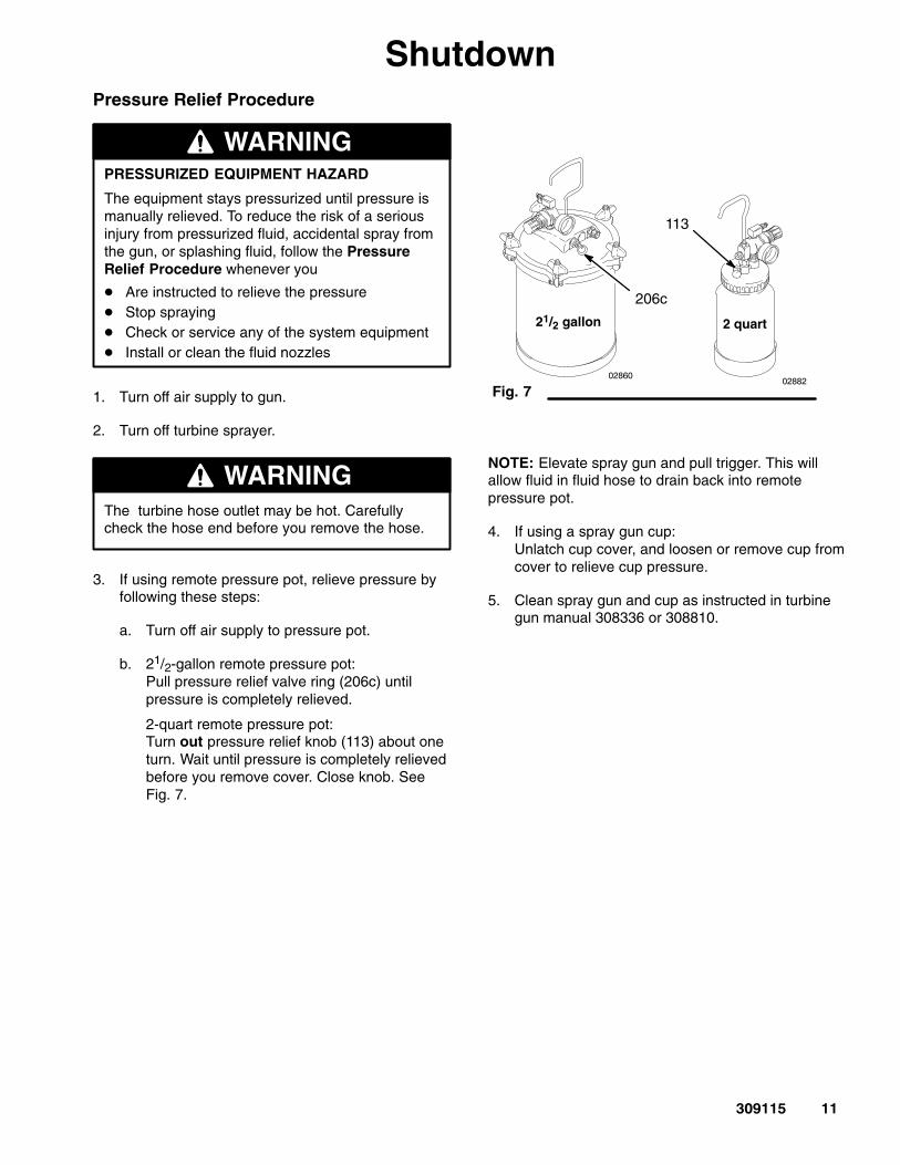
3. If using remote pressure pot, relieve pressure byfollowing these steps:
a. Turn off air supply to pressure pot.
b. 21/2-gallon remote pressure pot:Pull pressure relief valve ring (206c) untilpressure is completely relieved.
2-quart remote pressure pot:Turn out pressure relief knob (113) about oneturn. Wait until pressure is completely relievedbefore you remove cover. Close knob. SeeFig. 7.
Fig. 7
206c
�����
113
�����
21/2 gallon 2 quart
NOTE: Elevate spray gun and pull trigger. This willallow fluid in fluid hose to drain back into remotepressure pot.
4. If using a spray gun cup:Unlatch cup cover, and loosen or remove cup fromcover to relieve cup pressure.
5. Clean spray gun and cup as instructed in turbinegun manual 308336 or 308810.

����������������
MaintenanceDaily
Check the cart daily for cleanliness.
The compressor system is lifetime lubricated. The onlymaintenance required is filter cleaning andreplacement.
The compressor filter must be clean at all times toprovide sufficient air flow to cool the motor andpressurized air to the remote pressure pot. Check thefilter daily. Clean or replace as necessary.
To service the compressor filter
1. Turn off and unplug compressor.
2. Pinch filter (A) and remove by hand. See Fig. 8.
3. Clean or replace filter as follows:
a. Brush accumulated paint and dirt from surfaceof foam filter.
b. Rinse filter in water with mild detergent. Blowdry.
c. Replace filter if paint is caked on.
WARNINGTo avoid damage to the compressor and possibleelectric shock, never install a damp filter in thecompressor.
CAUTIONDust and dirt can accumulate during use and causeequipment damage. Do not operate the compressorwithout the filter installed.
Fig. 8
A
TI0100A
Weekly
Check hoses for cracks, leaks, and holes. Replace asnecessary.

����������������
TroubleshootingPROBLEM CAUSE SOLUTION
No fluid delivery No material, no remote containerpressurization, hose or pickup tubeclogged
Check container for material.
Check for leaks at the container gasket(2-quart pressure pot cover or21/2-gallon pressure pot wing nuts).Tighten wing nuts if loose.
Check for air flow from male quickdisconnect at compressor outlet(approx. 1/4 CFM).
Turn pressure regulator clockwise.Look for pressure on gauge. (If nopressure on gauge, check air line andfittings).
Check hole in 21/2-gallon pressure potcover under regulator or in 2-quartpressure pot cover at needle valve.
Clean if necessary.
Check for obstructions or kinks inhoses and fittings.
Check if fluid pickup tube is unplugged.Tighten.
Blow out and clear material hose.
Compressor not starting Cold weather operation See Cold Weather Operation onpage 10.

����������������
Repair
WARNINGTurn off turbine and unplug power for the following procedures.
Compressor/Cart Switch Replacement
See Fig. 9 and Parts Drawing on page 16.
1. To remove compressor power switch (28), wedgelarge flat blade screwdriver between top of switchand cart face plate.
2. Push down firmly on switch. Pry switch out farenough so two top locking tabs (A) are visible.
3. While maintaining outward pressure on switch,push down on two locking tabs with smallflat-blade screwdriver until they release and switchpops out.
4. Disconnect the two wires, and remove switch.
5. Reinstall by connecting wires to new switch. Snapswitch into place.
Fig. 9A
28
7936A
Power Cord Replacement
See Parts Drawing on page 16.
1. Remove four cart grill plate screws (23), andremove cart filter (9). Clean or replace filter asnecessary.
2. Replace power cord (29).
3. Reinstall cart filter.
Compressor Replacement
See Fig. 10, and Parts Drawing on page 16.
1. Remove four cart grill plate screws (23). Removecart filter (9) and compressor duct (10). Clean orreplace filter as necessary.
2. Remove air hose (12) from compressor.
3. Remove compressor mounting screws (11).
4. Disconnect motor wires, and remove compressor.
5. Install new compressor, and connect motor wires.
6. Reinstall hose on compressor.
7. Reinstall compressor duct and cart filter.
Fig. 10TI0101Bpower cord
capacitor
motor
Wiring Diagram
rocker switch
fan

����������������
Accessories
8483A
Pot Length (ft) Part No.
21/2gal 2 240074
2 qt
30 240071
Compressor Air Hose
Air Valve Kit240065
Tie Wrap Kit(10 pack)
103473
Length (ft) Part No.
30 240064
60 240079
Air & Material Hose
FS Part No.
3 240773
3 240103
Fluid Set (FS)/Spray Gun
Gun
960P
980P
40 240072
50 240073
60 240074
Length (ft) Part No.
20 240475
30 240476
Material Hose*
40 240477
50 240478
60 240479
* Material hose couplerM70693 may be used tocouple two materialhoses together.
Length (ft) Part No.
40 (B)
240058*
240283
Standard Turbine Air HoseBlack (B) or Grey (G)
20 (B)
30 (G) 240059**
40 (G) 240060
50 (G) 240061
60 (G) 240062
Standard M70604
� lined
240045
Pressure Pot
* Standard on GTS-2500** Standard on GTS-3800 and
GTS-4900
� See GTS-HVLP Fine Finish Systemsbrochure 300477 for all accessories.
� Non-Silicone Lubricant 111265 (4 oz) isavailable for fluid seals and wear areas.
Notes:
PTFE

29
7
3
6
5
4
9
10
19
25
2426
28
8
11
1213
13
15
18
21
22
23
7
1a
1c
1b1d
27
36
38
39
41
37
TI0102A
Bottom View
5557
247
56
1
5354
50
51
49
46
20
GTS-ProCart HVLP Compressor/CartModel 233059, Series A
bottom of cart
52
���������������
Parts Drawing

���������������
Parts ListGTS-ProCart HVLP Compressor/CartModel 233059, Series A
Ref No. Part No. Description Qty
Ref No. Part No. Description Qty
1 243596 HOUSING ASSY, cart 11a 191824 . WASHER, space 21b 113658 . NUT, crest, hat 21c 113647 . WHEEL 21d 111841 . WASHER, plain; 5/8 in. 22 240000 HANDLE, cart 13 114047 VALVE, check 14 178945 NUT, hex 15 M70809 FITTING, barbed 16 115833 COMPRESSOR, 240V 17 105328 SCREW, cap, hx hd 48 192798 PLATE, handle 29† 195862 FILTER, cart 110 192795 DUCT, compressor 111 112948 SCREW, machine, pan hd 312 192810 HOSE, air, cart 113 M71635 CLAMP, hose 215 193219 SPACER, foot 118 114270 KNOB 219 192800 RETAINER, handle 220 107557 SCREW, cap, hex hd 121 192802 SPACER, handle 222 196148 PLATE, grill, cart 123 106084 SCREW, mach, pan hd 424 114421 CONNECTOR, cord strain relief 125 192799 HANDLE, latch 126 192801 SCREW, shoulder 1
27 107262 TERMINAL, insulated, female 328 114293 SWITCH, rocker, red 129 114299 CORD SET, 0.6 m (24 in.) 136 M70604 TANK, paint, 21/2 gallon 137 240075 HOSE, air, quick disconnect;
1/4 in. x 24 in. 138 240481 HOSE, material, black;
3/8 in. x 30 ft 139 241335 HOSE, turbine air, gray; 30 ft 141 103473 TIE WRAP 1046 115836 GUARD, finger 147 115834 FAN, cooling 148 115835 BRACKET, capacitor (Capacitor location
is shown in Wiring Diagram on page 14.) 149 196146 RETAINER, spring 150 192778 RETAINER, filter 151 192792 PRE-FILTER 152 102040 NUT, lock 453 100270 SCREW, cap, hex head 454 100016 WASHER, lock 455 111705 SCREW, machine, filister head 456 111280 NUT, locking 557 100079 WASHER, spring-lock 458 240255 CONDUCTOR, electrical (Runs from
capacitor to Terminal 4 on rocker switch.
See Wiring Diagram on page 14.) 1115B315 WIRE, ground (not shown) 1
† Cart filters are available in 3 packs. Order 240274.
SpecificationsPower requirements 240V AC, 50/60 Hz, 1 Amp. . . . . . . . . . . . . . . . . . . . . . . . . . . . . . . . . . . . . . . . . . . . . . . . . . . . . . . . . . Power cord 1.5 mm2, 3 wire, 0.3 m (extension cord must be 3-wire,1.5 mm2, no longer than 15 m). . . . . . . . . . . . . . CFM unrestricted 0.4 cfm. . . . . . . . . . . . . . . . . . . . . . . . . . . . . . . . . . . . . . . . . . . . . . . . . . . . . . . . . . . . . . . . . . . . . . . . . . . . . . . HP 1/16 HP. . . . . . . . . . . . . . . . . . . . . . . . . . . . . . . . . . . . . . . . . . . . . . . . . . . . . . . . . . . . . . . . . . . . . . . . . . . . . . . . . . . . . . . . . . Maximum working pressure 15 psi (104 kPa, 1.0 bar). . . . . . . . . . . . . . . . . . . . . . . . . . . . . . . . . . . . . . . . . . . . . . . . . . . . . . Maximum compressor hose length 60 ft (18 m). . . . . . . . . . . . . . . . . . . . . . . . . . . . . . . . . . . . . . . . . . . . . . . . . . . . . . . . . . . . Wetted parts
Material hose low-density polyethylene/rubber blend. . . . . . . . . . . . . . . . . . . . . . . . . . . . . . . . . . . . . . . . . . . . . . . . . . . . . 21/2-gallon (9.5 liter) remote pressure pot steel with solvent-resistant finish, EPDM gasket (standard). . . . . . . . . . .
Compressor/Cart shipping weight (without packaging or hoses) 22 lb (10 kg). . . . . . . . . . . . . . . . . . . . . . . . . . . . . . . . . . Sound levels per ISO 3744
Sound power level 74.0 dB(A). . . . . . . . . . . . . . . . . . . . . . . . . . . . . . . . . . . . . . . . . . . . . . . . . . . . . . . . . . . . . . . . . . . . . . . . . Sound pressure level 70.0 dB(A). . . . . . . . . . . . . . . . . . . . . . . . . . . . . . . . . . . . . . . . . . . . . . . . . . . . . . . . . . . . . . . . . . . . . .
� is a registered trademark PTFE

����������������
Graco Standard WarrantyGraco warrants all equipment manufactured by Graco and bearing its name to be free from defects in material and workmanship on thedate of sale by an authorized Graco distributor to the original purchaser for use. With the exception of any special, extended, or limitedwarranty published by Graco, Graco will, for a period of twelve months from the date of sale, repair or replace any part of the equipmentdetermined by Graco to be defective. This warranty applies only when the equipment is installed, operated and maintained inaccordance with Graco’s written recommendations.
This warranty does not cover, and Graco shall not be liable for general wear and tear, or any malfunction, damage or wear caused byfaulty installation, misapplication, abrasion, corrosion, inadequate or improper maintenance, negligence, accident, tampering, orsubstitution of non-Graco component parts. Nor shall Graco be liable for malfunction, damage or wear caused by the incompatibility ofGraco equipment with structures, accessories, equipment or materials not supplied by Graco, or the improper design, manufacture,installation, operation or maintenance of structures, accessories, equipment or materials not supplied by Graco.
This warranty is conditioned upon the prepaid return of the equipment claimed to be defective to an authorized Graco distributor forverification of the claimed defect. If the claimed defect is verified, Graco will repair or replace free of charge any defective parts. Theequipment will be returned to the original purchaser transportation prepaid. If inspection of the equipment does not disclose any defectin material or workmanship, repairs will be made at a reasonable charge, which charges may include the costs of parts, labor, andtransportation.
THIS WARRANTY IS EXCLUSIVE, AND IS IN LIEU OF ANY OTHER WARRANTIES, EXPRESS OR IMPLIED, INCLUDING BUTNOT LIMITED TO WARRANTY OF MERCHANTABILITY OR WARRANTY OF FITNESS FOR A PARTICULAR PURPOSE.
Graco’s sole obligation and buyer’s sole remedy for any breach of warranty shall be as set forth above. The buyer agrees that no otherremedy (including, but not limited to, incidental or consequential damages for lost profits, lost sales, injury to person or property, or anyother incidental or consequential loss) shall be available. Any action for breach of warranty must be brought within two (2) years of thedate of sale.
Graco makes no warranty, and disclaims all implied warranties of merchantability and fitness for a particular purpose in connectionwith accessories, equipment, materials or components sold but not manufactured by Graco. These items sold, but not manufacturedby Graco (such as electric motors, switches, hose, etc.), are subject to the warranty, if any, of their manufacturer. Graco will providepurchaser with reasonable assistance in making any claim for breach of these warranties.
In no event will Graco be liable for indirect, incidental, special or consequential damages resulting from Graco supplying equipmenthereunder, or the furnishing, performance, or use of any products or other goods sold hereto, whether due to a breach of contract,breach of warranty, the negligence of Graco, or otherwise.
FOR GRACO CANADA CUSTOMERSThe parties acknowledge that they have required that the present document, as well as all documents, notices and legal proceedingsentered into, given or instituted pursuant hereto or relating directly or indirectly hereto, be drawn up in English. Les partiesreconnaissent avoir convenu que la rédaction du présente document sera en Anglais, ainsi que tous documents, avis et procéduresjudiciaires exécutés, donnés ou intentés à la suite de ou en rapport, directement ou indirectement, avec les procedures concernées.
ADDITIONAL WARRANTY COVERAGEGraco does provide extended warranty and wear warranty for products described in the “Graco Contractor Equipment WarrantyProgram”.
Graco Phone NumberTO PLACE AN ORDER, contact your Graco distributor, or call this number to identify the distributor closest to you:
1–800–690–2894 Toll Free
All written and visual data contained in this document reflect the latest product information available at the time of publication.Graco reserves the right to make changes at any time without notice.
Sales Offices: Minneapolis, DetroitForeign Offices: Belgium, Korea, Hong Kong, Japan
GRACO INC. P.O. BOX 1441 MINNEAPOLIS, MN 55440–1441www.graco.com
PRINTED IN USA 309115 01/2000, Revised 09/2003