308049V, 19 Liter (5 Gallon) Wiper Plates Instructions and Parts … · 2018-12-19 · 308049 5...
22
Instructions--Parts List Important Safety Instructions Read all warnings and instructions in this manual. Save these instructions. See page 2 for Table of Contents and List of Models. 19 LITER (5 GALLON) Wiper Plates For straight-sided or tapered pails. Fit Check-Matet Pumps on a Pneumatic Elevator Cart or Ram. For professional use only. Not approved to European explosive atmosphere requirements. U.S. Patent No. 5,117,998 308049V EN 0212A 01115 Model 222812 Model 222909
-
Upload
vuongkhuong -
Category
Documents
-
view
213 -
download
0
Transcript of 308049V, 19 Liter (5 Gallon) Wiper Plates Instructions and Parts … · 2018-12-19 · 308049 5...
Instructions--Parts List
Important Safety InstructionsRead all warnings and instructions in this manual.Save these instructions.
See page 2 for Table of Contents and List ofModels.
19 LITER (5 GALLON)
Wiper PlatesFor straight-sided or tapered pails. Fit Check-Matet Pumps on aPneumatic Elevator Cart or Ram. For professional use only.
Not approved to European explosive atmosphere requirements.U.S. Patent No. 5,117,998
308049VEN
0212A
01115
Model 222812
Model 222909

2 308049
Table of ContentsList of Models 2. . . . . . . . . . . . . . . . . . . . . . . . . . . . . . . . . .Symbols 3. . . . . . . . . . . . . . . . . . . . . . . . . . . . . . . . . . . . . .Warnings 3. . . . . . . . . . . . . . . . . . . . . . . . . . . . . . . . . . . . . .Installation (All Wiper Plates) 5. . . . . . . . . . . . . . . . . . . . .Installation on a Ram
(Carbon Steel or Aluminum Plates) 6. . . . . . . . . . . . .Installation on a Cart
(Carbon Steel or Aluminum Plates) 8. . . . . . . . . . . . .
Installation on a Ram (Stainless Steel Plates) 10. . . . .Installation on a Cart (Stainless Steel Plates) 12. . . . . .Parts Drawings and Lists 14. . . . . . . . . . . . . . . . . . . . . . .Accessories 21. . . . . . . . . . . . . . . . . . . . . . . . . . . . . . . . . .Technical Data 21. . . . . . . . . . . . . . . . . . . . . . . . . . . . . . . .Graco Standard Warranty 22. . . . . . . . . . . . . . . . . . . . . .Graco Information 22. . . . . . . . . . . . . . . . . . . . . . . . . . . . .
List of Models
Model No. Series Plate Material Wiper MaterialBackupMaterial
InstallationPages Parts Pages
222812 B Carbon Steel Buna-N UHMWPE 6--9 14
235516 B Carbon Steel PTFE-coated UHMWPE 6--9 15
222909 A Stainless Steel PTFE-coated UHMWPE 10--13 16--17
241081 A Carbon Steel Buna-N UHMWPE 6--9 18
918409 B Carbon Steel Buna-N UHMWPE 6--9 19
C50260 B Carbon Steel Buna-N UHMWPE 6--9 14

308049 3
SymbolsWarning Symbol
WARNINGThis symbol alerts you to the possibility of seriousinjury or death if you do not follow the instructions.
Caution Symbol
CAUTIONThis symbol alerts you to the possibility of damage toor destruction of equipment if you do not follow theinstructions.
WARNING
INSTRUCTIONS
EQUIPMENT MISUSE HAZARD
Equipment misuse can cause the equipment to rupture or malfunction and result in serious injury.
D This equipment is for professional use only.
D Read all instruction manuals, tags, and labels before operating the equipment.
D Use the equipment only for its intended purpose. If you are uncertain about usage, call your Gracodistributor.
D Do not alter or modify this equipment. Use only genuine Graco parts and accessories.
D Check equipment daily. Repair or replace worn or damaged parts immediately.
D Use fluids and solvents which are compatible with the equipment wetted parts. Refer to the Tech-nical Data section of all equipment manuals. Read the fluid and solvent manufacturer’s warnings.
D Comply with all applicable local, state, and national fire, electrical, and safety regulations.
MOVING PARTS HAZARD
Moving parts, such as the priming piston and wiper plate, can pinch or amputate your fingers.
D Keep clear of all moving parts when starting or operating the pump.
D Keep hands and fingers away from the priming piston during operation and whenever the pump ischarged with air.
D Keep your hands away from the wiper plate and the lip of the pail while the ram is operating.
D Before servicing the equipment, follow the Pressure Relief Procedure on page 5 to prevent theequipment from starting unexpectedly.

4 308049
Notes

308049 5
Installation (All Wiper Plates)Pressure Relief Procedure
WARNINGSKIN INJECTION HAZARDThe system pressure must be manuallyrelieved to prevent the system fromstarting or spraying accidentally. Fluid
under high pressure can be injected through theskin and cause serious injury. To reduce the risk ofan injury from injection, splashing fluid, or movingparts, follow the Pressure Relief Procedurewhenever you:
D are instructed to relieve the pressure,D stop spraying/dispensing,D check or service any of the system equipment,D or install or clean the spray tip/nozzle.
1. Lock the gun/valve trigger safety.
2. Close the pump air bleed valve (required in yoursystem).
3. Shut off the main air bleed valve (required in yoursystem).
4. Unlock the gun/valve trigger safety.
5. Hold a metal part of the gun/valve firmly to the sideof a grounded metal pail, and trigger the gun/valveto relieve pressure.
6. Lock the gun/valve trigger safety.
7. Open the drain valve (required in your system)and/or the pump bleeder valve, having a containerready to catch the drainage.
8. Leave the drain valve open until you are ready tospray again.
If you suspect that the spray tip/nozzle or hose iscompletely clogged, or that pressure has not been fullyrelieved after following the steps above, very slowlyloosen the tip guard retaining nut or hose end couplingand relieve pressure gradually, then loosen completely.Now clear the tip/nozzle or hose.

6 308049
Installation on a Ram(Carbon Steel or Aluminum Plates)
Installation
Reference letters and numbers in the text refer to Figs.1--4 and the Parts Drawings on pages 14--15.
WARNINGMOVING PARTS HAZARDMoving parts can pinch or amputate yourfingers. When the pump is operating andwhen raising or lowering the ram, keep
your fingers and hands away from the primingpiston and the lip of the pail.
WARNINGTo reduce the risk of serious injury, whenever youare instructed to relieve pressure, always follow thePressure Relief Procedure on page 5.
1. Relieve the pressure.
2. Install the wiper plate (A) onto the pump intake (B),with the wiper plate vent handle (C) facing the frontof the ram. Secure by tightening the setscrew (3).See Fig. 1.
3. The wiper plate is supplied for use with 19 liter (5gallon) straight sided pails, but it can be easilymodified for use with tapered pails. See steps aand b.
a. To use the wiper plate with tapered pails,the large spacer (19) must be removed. Work-ing from the bottom, use a screwdriver to prythe spacer loose. Work it upward so it is com-pletely above the flange (D) of the wiper plate.See Fig. 2. Next, by hand, angle the spacerand work it off the plate, pulling it down overthe flange and bottom wipers (E). See Fig. 3.Save the spacer, as it is required for otherapplications.
b. To reinstall the spacer for use with astraight sided pail, first make sure the largediameter of the spacer (19) is facing down.Work the spacer up over the wiper plate byhand, so it is completely above the flange (D)of the wiper plate. See Fig. 3. Then, workingfrom the top, use a screwdriver to position thespacer between the flange (D) and the wipers(E). See Fig. 4.
4. Connect a 610 mm (24 in.), 1/4 in. (6.3 mm) ODnylon tube (F) with a 1/8 npt(f) fitting (H) from theram’s air assist tube fitting (G) to the air assistcheck valve (21) on the wiper plate.
5. Refer to the separate ram and pump manuals forset-up and operating instructions.
Maintenance
If the wiper plate does not come out of the pail easilywhen the pump is being raised, the air assist tube (F),fitting (H), and check valve (21) may be plugged. Thisprevents air from reaching the underside of the plate toassist in raising it from the pail.
WARNINGTo reduce the risk of serious injury whenever youare instructed to relieve pressure, always follow thePressure Relief Procedure on page 5.
Relieve the pressure. Refer to the Parts Drawings onpages 14--15 and disassemble the air assist checkvalve as shown. Clear the tube (F) and the port in thewiper plate. Clean all parts of the check valve assem-bly, and reassemble.

308049 7
Installation on a Ram(Carbon Steel and Aluminum Plates)
Installing the Wiper Plate on a Ram(Model 222812 shown; large diameter ofspacer facing down)
06540AFig. 1
1
A
B C
3
F
H
G
To use Model 222812 and 235516, Plates with taperedpails, the spacer (19) must be removed. See page 6,and Figs. 2--4.
19 1
0248A
Fig. 2
19
D
E
0249A
Fig. 3
D
E19
0251A
Fig. 4
19
DE

8 308049
Installation on a Cart(Carbon Steel and Aluminum Plates)
Installation
Reference letters and numbers in the text refer to Figs.5--8 and the Parts Drawings on pages 14--15.
WARNINGMOVING PARTS HAZARDMoving parts can pinch or amputate yourfingers. When the pump is operating andwhen raising or lowering the ram, keep
your fingers and hands away from the primingpiston and the lip of the pail.
WARNINGTo reduce the risk of serious injury whenever youare instructed to relieve pressure, always follow thePressure Relief Procedure on page 5.
1. Relieve the pressure.
2. Install the wiper plate (A) onto the pump intake (B),with the wiper plate vent handle (C) facing the frontof the cart. Secure by tightening the setscrew (3).See Fig. 5.
3. The wiper plate is supplied for use with 19 liter (5gallon) straight sided pails on a ram. It must bemodified for use with the pneumatic elevator cart.See steps a and b, following.
a. To use the wiper plate with straight sidedpails, the large spacer (19) must be inverted.Working from the bottom, use a screwdriver topry the spacer loose. Work it upward so it iscompletely above the flange (D) of the wiperplate. See Fig. 6. Next, by hand, angle thespacer and work it off the plate, pulling it downover the flange and bottom wipers (E). SeeFig. 7. Turn the spacer so the large diameteris facing up. Work the spacer up over thewiper plate by hand, so it is completely abovethe flange (D) of the wiper plate. Working fromthe top, use a screwdriver to position thespacer between the flange (D) and the wipers(E). See Fig. 8.
b. To use the wiper plate with tapered pails,the large spacer (19) must be removed. Work-ing from the bottom, use a screwdriver to prythe spacer loose. Work it upward so it is com-pletely above the flange (D) of the wiper plate.See Fig. 6. Next, by hand, angle the spacerand work it off the plate, pulling it down overthe flange and bottom wipers (E). See Fig. 7.Save the spacer, as it is required for otherapplications.
4. Install Cart Accessory Kit 224376. See 308087 fordetails.
5. Refer to the separate cart and pump manuals forset-up and operating instructions.
Maintenance
If the wiper plate does not come out of the pail easilywhen the pump is being raised, the air assist tube (F),fitting (H), or check valve (21) may be plugged. Thisprevents air from reaching the underside of the plate toassist in raising it from the pail.
WARNINGTo reduce the risk of serious injury whenever youare instructed to relieve pressure, always follow thePressure Relief Procedure on page 5.
Relieve the pressure. Refer to the Parts Drawings onpages 14--15 and disassemble the air assist checkvalve as shown. Clear the tube (F) and the port in thewiper plate. Clean all parts of the check valve assem-bly, and reassemble.

308049 9
Installation on a Cart(Carbon Steel and Aluminum Plates)
Installing the Wiper Plate on aPneumatic Elevator Cart(Model 222812 shown;large diameter of spacer facing up)
0252D
Fig. 5
1
2
A
C
3 B
H
Part of Kit 224376 (See 308087).
To use Model 222812 and 235516 Plates with taperedpails, the spacer (19) must be removed. See page 8,and Figs. 6--8.
19
2
1
F
0248AFig. 6
19D
E
0249A
Fig. 7
D
E19
Fig. 8
19
0251AD
E
10 308049
Installation on a Ram(Stainless Steel Plates)
Installation
Reference letters and numbers in the text refer to Figs.9--12 and the Parts Drawing on page 16.
WARNINGMOVING PARTS HAZARDMoving parts can pinch or amputate yourfingers. When the pump is operating andwhen raising or lowering the ram, keep
your fingers and hands away from the primingpiston and lip of the pail.
WARNINGTo reduce the risk of serious injury whenever youare instructed to relieve pressure, always follow thePressure Relief Procedure on page 5.
1. Relieve the pressure.
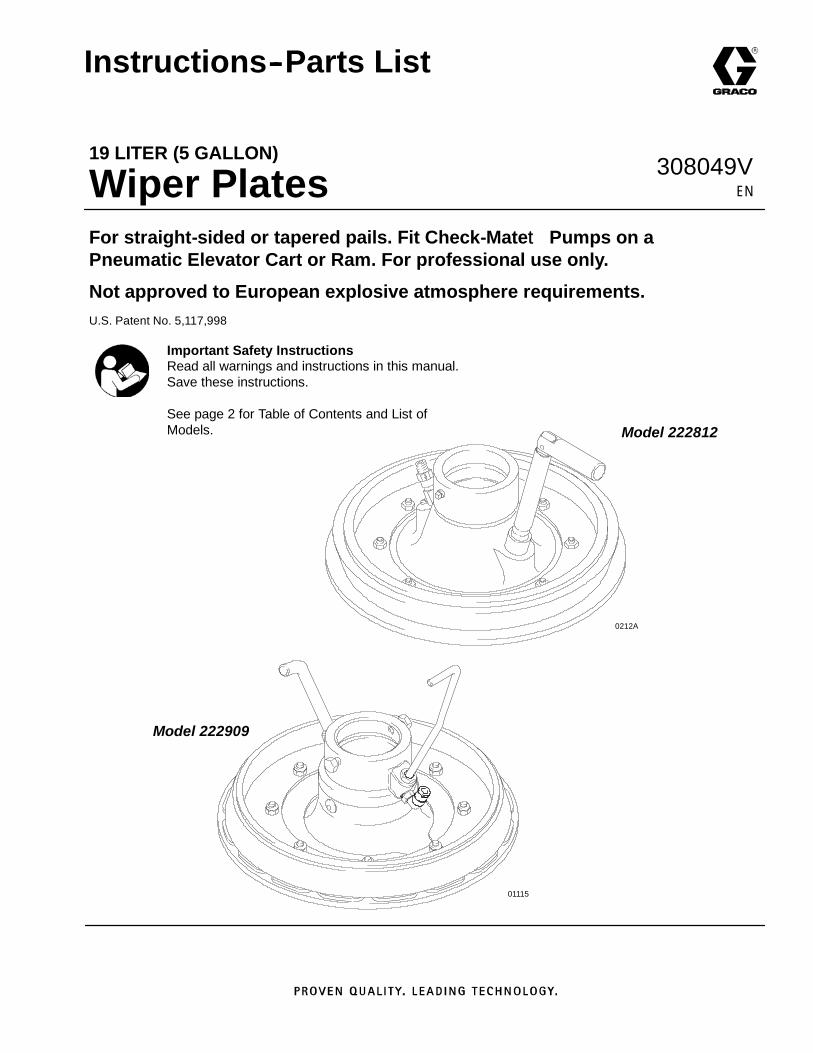
2. Install the wiper plate (A) onto the pump intake (B),with the wiper plate vent handle (C) facing the leftof the ram. Secure by tightening the setscrews(17). See Fig. 9.
3. The wiper plate is supplied for use with 19 liter (5gallon) straight sided pails, but it can be easilymodified for use with tapered pails. See steps aand b
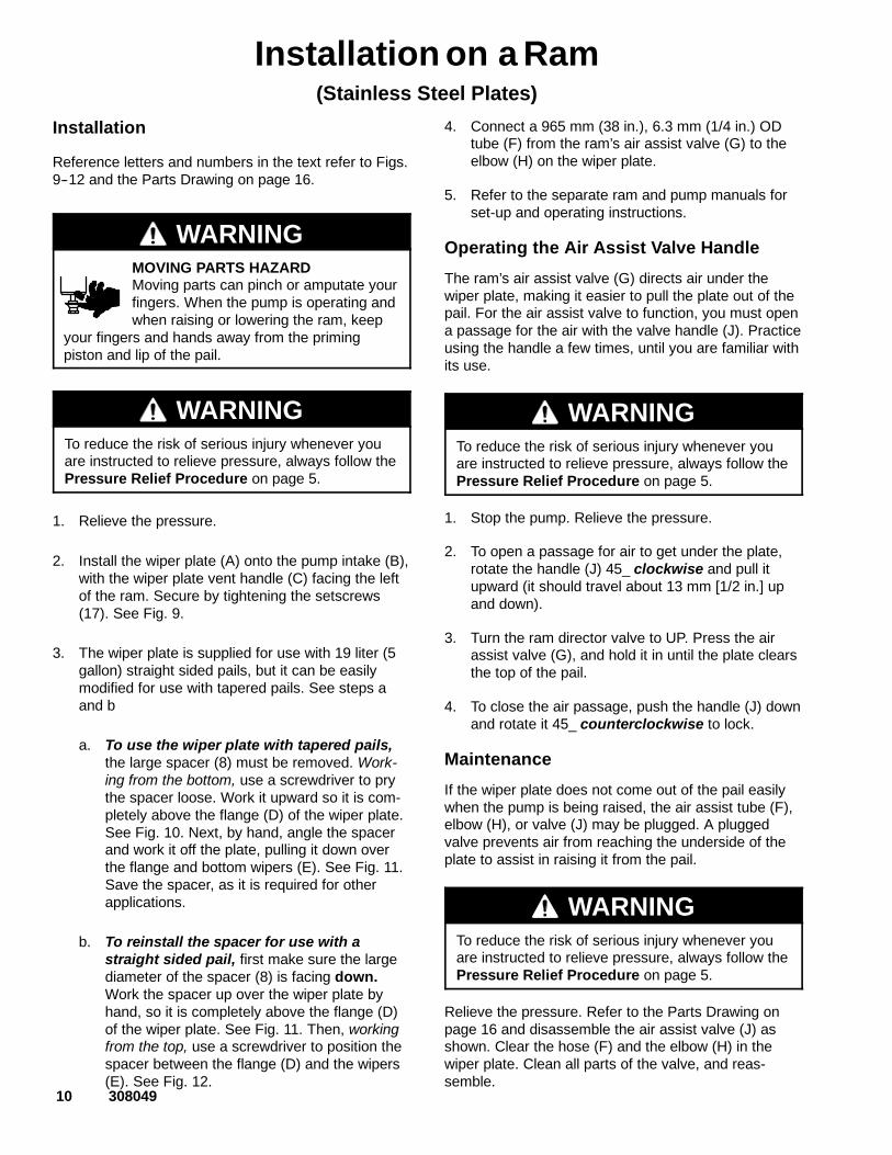
a. To use the wiper plate with tapered pails,the large spacer (8) must be removed. Work-ing from the bottom, use a screwdriver to prythe spacer loose. Work it upward so it is com-pletely above the flange (D) of the wiper plate.See Fig. 10. Next, by hand, angle the spacerand work it off the plate, pulling it down overthe flange and bottom wipers (E). See Fig. 11.Save the spacer, as it is required for otherapplications.
b. To reinstall the spacer for use with astraight sided pail, first make sure the largediameter of the spacer (8) is facing down.Work the spacer up over the wiper plate byhand, so it is completely above the flange (D)of the wiper plate. See Fig. 11. Then, workingfrom the top, use a screwdriver to position thespacer between the flange (D) and the wipers(E). See Fig. 12.
4. Connect a 965 mm (38 in.), 6.3 mm (1/4 in.) ODtube (F) from the ram’s air assist valve (G) to theelbow (H) on the wiper plate.
5. Refer to the separate ram and pump manuals forset-up and operating instructions.
Operating the Air Assist Valve Handle
The ram’s air assist valve (G) directs air under thewiper plate, making it easier to pull the plate out of thepail. For the air assist valve to function, you must opena passage for the air with the valve handle (J). Practiceusing the handle a few times, until you are familiar withits use.
WARNINGTo reduce the risk of serious injury whenever youare instructed to relieve pressure, always follow thePressure Relief Procedure on page 5.
1. Stop the pump. Relieve the pressure.
2. To open a passage for air to get under the plate,rotate the handle (J) 45_ clockwise and pull itupward (it should travel about 13 mm [1/2 in.] upand down).
3. Turn the ram director valve to UP. Press the airassist valve (G), and hold it in until the plate clearsthe top of the pail.
4. To close the air passage, push the handle (J) downand rotate it 45_ counterclockwise to lock.
Maintenance
If the wiper plate does not come out of the pail easilywhen the pump is being raised, the air assist tube (F),elbow (H), or valve (J) may be plugged. A pluggedvalve prevents air from reaching the underside of theplate to assist in raising it from the pail.
WARNINGTo reduce the risk of serious injury whenever youare instructed to relieve pressure, always follow thePressure Relief Procedure on page 5.
Relieve the pressure. Refer to the Parts Drawing onpage 16 and disassemble the air assist valve (J) asshown. Clear the hose (F) and the elbow (H) in thewiper plate. Clean all parts of the valve, and reas-semble.
308049 11
Installation on a Ram(Stainless Steel Plates)
Installing the Wiper Plate on a Ram(large diameter of spacer facing down)
06754C
Fig. 9
1
A
B
C
F
H
G
17
J
To use Model 222909 Plate with a tapered pail, the spacer (8)must be removed. See page 10, and Figs. 10--12.
8
F
1
Fig. 10
D
E 01116
8
Fig. 1101117
D
E
8
Fig. 1201118D
E
8

12 308049
Installation on a Cart(Stainless Steel Plates)
InstallationReference letters and numbers in the text refer to Figs.13--16 and the Parts Drawing on page 16.
WARNINGMOVING PARTS HAZARDMoving parts can pinch or amputate yourfingers. When the pump is operating andwhen raising or lowering the ram, keep
your fingers and hands away from the primingpiston and the lip of the fluid container.
WARNINGTo reduce the risk of serious injury whenever youare instructed to relieve pressure, always follow thePressure Relief Procedure on page 5.
1. Relieve the pressure.
2. Install the wiper plate (A) onto the pump intake (B),with the wiper plate vent handle (C) facing the leftof the cart. Secure by tightening the setscrews(17). See Fig. 13.
3. The wiper plate is supplied for use with 19 liter (5gallon) straight sided pails on a ram. It must bemodified for use with the pneumatic elevator cart.See steps a and b following.
a. To use the wiper plate with straight sidedpails, the large spacer (8) must be inverted.Working from the bottom, use a screwdriver topry the spacer loose. Work it upward so it iscompletely above the flange (D) of the wiperplate. See Fig. 14. Next, by hand, angle thespacer and work it off the plate, pulling it downover the flange and bottom wipers (E). SeeFig. 15. Turn the spacer so the large diameteris facing up. Work the spacer up over thewiper plate by hand, so it is completely abovethe flange (D) of the wiper plate. Working fromthe top, use a screwdriver to position thespacer between the flange (D) and the wipers(E). See Fig. 16.
b. To use the wiper plate with tapered pails,the large spacer (8) must be removed. Work-ing from the bottom, use a screwdriver to prythe spacer loose. Work it upward so it is com-pletely above the flange (D) of the wiper plate.See Fig. 14. Next, by hand, angle the spacerand work it off the plate, pulling it down overthe flange and bottom wipers (E). See Fig. 15.Save the spacer, as it is required for otherapplications.
4. Install Cart Accessory Kit 224376. See 308199 fordetails.
5. Refer to the separate cart and pump manuals forset-up and operating instructions.
Operating the Air Assist Valve Handle
The cart’s air assist toggle valve (G) directs air underthe wiper plate, making it easier to pull the plate out ofthe pail. Refer to manual 308199 for instructions onchanging pails using the air assist valve.
For the air assist valve to function, you must open apassage for the air with the valve handle (J). Practiceusing the handle a few times, until you are familiar withits use.
WARNINGTo reduce the risk of serious injury whenever youare instructed to relieve pressure, always follow thePressure Relief Procedure on page 5.
1. Relieve the pressure.
2. To open a passage for air to get under the plate,rotate the handle (J) 45_ clockwise and pull itupward (it should travel about 13 mm [1/2 in.] upand down).
3. To close the air passage, push the handle (J) downand rotate it 45_ counterclockwise to lock.
Maintenance
If the wiper plate does not come out of the pail easilywhen the pump is being raised, the air assist tube (F),elbow (H), or valve (J) may be plugged. A pluggedvalve prevents air from reaching the underside of theplate to assist in raising it from the pail.
WARNINGTo reduce the risk of serious injury whenever youare instructed to relieve pressure, always follow thePressure Relief Procedure on page 5.
Relieve the pressure. Refer to the Parts Drawing onpage 16 and disassemble the air assist valve (J) asshown. Clear the hose (F) and the elbow (H) in thewiper plate. Clean all parts of the valve, and reas-semble.

308049 13
Installation on a Cart(Stainless Steel Plates)
Installing the Wiper Plate on aPneumatic Elevator Cart(large diameter of spacer facing up)
Fig. 13
1
2
01096
A
B
CH
G
Part of Kit 224376; see 308199.
17
J
To use Model 222909 Plate with a tapered pail, the spacer (8)must be removed. See page 12, and Figs. 14--16.
F
81
2
Fig. 14
D
E 01116
8
Fig. 1501117
D
E
8
Fig. 16D
E01118
8

0254B
1
2
4
3
21
6
16
14
9
15
5
19
12
13
0254D
14 308049
PartsModel C50260, Series BModel 222812, Series BCarbon Steel Wiper Platewith Buna-N Wiperand UHMWPE Backup
Ref. PartNo. No. Description Qty
Ref. PartNo. No. Description Qty
1 101831 PIN, spring, straight 12 177542 HANDLE 13 100421 SETSCREW, socket hd, cup point;
5/16--18 x 3/8 in. (9.5 mm) long 24 166560 STEM, probe 15n 184420 WIPER; synthetic rubber 16 109469 SCREW, machine, flat-hd;
zinc-plated carbon steel;1/4--20 x 1 in. (25 mm) long 8
9 184419 CLAMP, retainingzinc-plated carbon steel 1
12 222764 PLATE, wiper;zinc-plated carbon steel 1
13 109458 O-RING; fluoroelastomer 114 102040 NUT, hex, self-locking;
with nylon insert; 1/4--20 unc--3b 815n 184421 WIPER; polyethylene
(Model 222812 only) 116 184418 CLAMP, retaining;
zinc-plated carbon steel 119 276049 SPACER; polyurethane 121 114317 VALVE, check, air assist 1
n Keep these spare parts on hand to reduce down time.

01456A
1
2
4
3
6
16
14
9
15
5
19
12 20
21
13
308049 15
PartsModel 235516, Series BCarbon Steel Wiper Platewith PTFE-coated Wiperand UHMWPE Backup
Ref. PartNo. No. Description Qty
Ref. PartNo. No. Description Qty
1 101831 PIN, spring, straight 12 177542 HANDLE 13 100421 SETSCREW, socket hd, cup point;
5/16--18 x 3/8 in. (9.5 mm) long 14 166560 STEM, probe 15n 184552 WIPER; nitrile/PTFE 16 109469 SCREW, machine, flat-hd;
zinc-plated carbon steel;1/4--20 x 1 in. (25 mm) long 8
9 184419 CLAMP, retainingzinc-plated carbon steel 1
12 222764 PLATE, wiper;zinc-plated carbon steel 1
13 109458 O-RING; fluoroelastomer 114 102040 NUT, hex, self-locking;
with nylon insert; 1/4--20 unc--3b 815n 184421 WIPER; polyethylene 116 184418 CLAMP, retaining;
zinc-plated carbon steel 119 276049 SPACER; polyurethane 120n 184551 WIPER; polyethylene 121 114317 VALVE, check, air assist 1
n Keep these spare parts on hand to reduce down time.
1
2
4
13
6
16
11
14
7
8
10
9
15
5
17
12
01119
20
3
19
19
14 (Ref)
K
L 01213
14 13
1915
19
K
1
L11
12
16
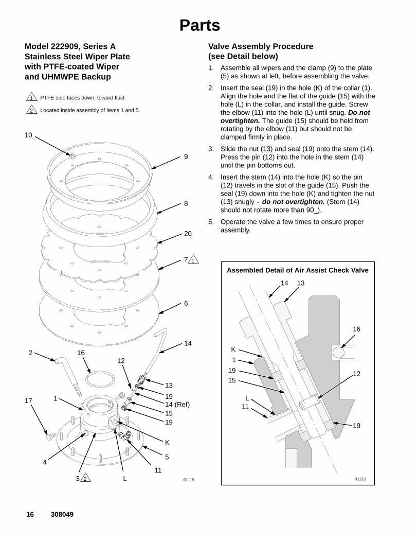
Assembled Detail of Air Assist Check Valve
1
2
PTFE side faces down, toward fluid.
Located inside assembly of items 1 and 5.
2
1
16 308049
PartsModel 222909, Series AStainless Steel Wiper Platewith PTFE-coated Wiperand UHMWPE Backup
Valve Assembly Procedure(see Detail below)1. Assemble all wipers and the clamp (9) to the plate
(5) as shown at left, before assembling the valve.
2. Insert the seal (19) in the hole (K) of the collar (1).Align the hole and the flat of the guide (15) with thehole (L) in the collar, and install the guide. Screwthe elbow (11) into the hole (L) until snug. Do notovertighten. The guide (15) should be held fromrotating by the elbow (11) but should not beclamped firmly in place.
3. Slide the nut (13) and seal (19) onto the stem (14).Press the pin (12) into the hole in the stem (14)until the pin bottoms out.
4. Insert the stem (14) into the hole (K) so the pin(12) travels in the slot of the guide (15). Push theseal (19) down into the hole (K) and tighten the nut(13) snugly -- do not overtighten. (Stem (14)should not rotate more than 90_).
5. Operate the valve a few times to ensure properassembly.

308049 17
PartsModel 222909, Series AStainless Steel Wiper Platewith PTFE-coated Wiperand UHMWPE Backup
Ref. PartNo. No. Description Qty
Ref. PartNo. No. Description Qty
1 184471 COLLAR, wiper plate; sst 12 184481 STEM, probe; sst 13 109482 O-RING; PTFE 14 103972 SCREW, drive, u-type;
0.188 in. (5 mm) long 35 222915 PLATE, wiper; sst 16n 184421 WIPER; polyethylene 17n 184552 WIPER; nitrile/PTFE 18 276049 SPACER; polyurethane 19 184477 CLAMP, retaining; sst 110 551413 NUT, lock, hex; w/nylon insert;
1/4--20 unc--2b 811 109506 ELBOW, tube fitting, 90_;
1/8 npt(m) x 1/4 in. (6.3 mm) tube size 1
12 109479 PIN, spring, straight;3/32 in. size x 3/8 in. (9.5 mm) long 1
13 184482 NUT, retainer; sst 114 184479 STEM, valve; sst 115n 184531 GUIDE, valve; sst 116 109458 O-RING; fluoroelastomer 117 109477 SCREW, cap, hex head;
5/16--18 unc--2a; 1/2 in. (13 mm) long 219n 184530 SEAL, valve; PTFE 220n 184551 WIPER; polyethylene 121 114317 VALVE, check, air assist 1
n Keep these spare parts on hand to reduce down time.

1
2
4
3
21
6
16
14
9
15
5
19
12
13
23
24
25
0254D
18 308049
PartsModel 241081, Series ACarbon Steel Wiper Platewith Buna-N Wiperand UHMWPE Backup
Ref. PartNo. No. Description Qty
Ref. PartNo. No. Description Qty
1 101831 PIN, spring, straight 12 177542 HANDLE 13 100421 SETSCREW, socket hd, cup point;
5/16--18 x 3/8 in. (9.5 mm) long 24 166560 STEM, probe 15n 194146 WIPER; synthetic rubber 16 109469 SCREW, machine, flat-hd;
zinc-plated carbon steel;1/4--20 x 1 in. (25 mm) long 8
9 194151 CLAMP, retainingzinc-plated carbon steel 1
12 241080 PLATE, wiper;zinc-plated carbon steel 1
13 109458 O-RING; fluoroelastomer 114 102040 NUT, hex, self-locking;
with nylon insert; 1/4--20 unc--3b 815n 194147 WIPER; polyethylene 116 194149 CLAMP, retaining;
zinc-plated carbon steel 119 276049 SPACER; polyurethane 121 C20467 VALVE, check, air assist 123 111842 FITTING, elbow, pipe 45_ 124 155665 UNION, adapter 125 208391 VALVE, ball 1
n Keep these spare parts on hand to reduce down time.
0254B
1
2
4
3
6
16
14
9
15
5
17
12
13
18
19
20
21
0254D
308049 19
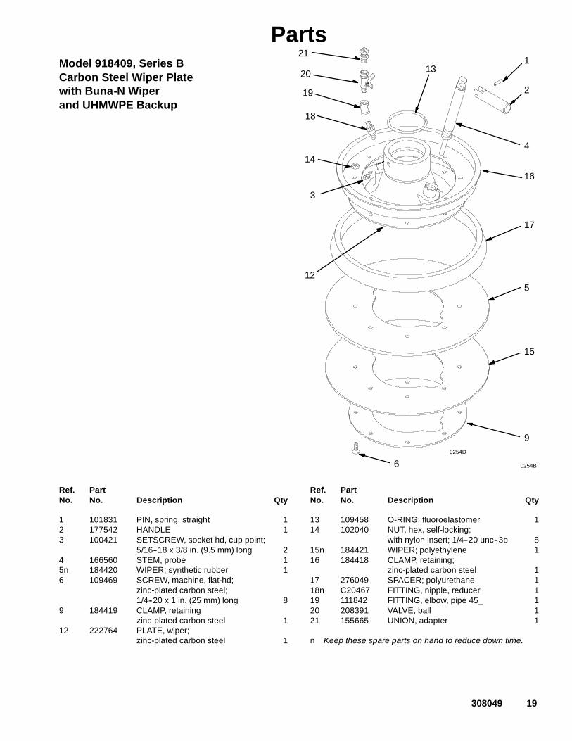
PartsModel 918409, Series BCarbon Steel Wiper Platewith Buna-N Wiperand UHMWPE Backup
Ref. PartNo. No. Description Qty
Ref. PartNo. No. Description Qty
1 101831 PIN, spring, straight 12 177542 HANDLE 13 100421 SETSCREW, socket hd, cup point;
5/16--18 x 3/8 in. (9.5 mm) long 24 166560 STEM, probe 15n 184420 WIPER; synthetic rubber 16 109469 SCREW, machine, flat-hd;
zinc-plated carbon steel;1/4--20 x 1 in. (25 mm) long 8
9 184419 CLAMP, retainingzinc-plated carbon steel 1
12 222764 PLATE, wiper;zinc-plated carbon steel 1
13 109458 O-RING; fluoroelastomer 114 102040 NUT, hex, self-locking;
with nylon insert; 1/4--20 unc--3b 815n 184421 WIPER; polyethylene 116 184418 CLAMP, retaining;
zinc-plated carbon steel 117 276049 SPACER; polyurethane 118n C20467 FITTING, nipple, reducer 119 111842 FITTING, elbow, pipe 45_ 120 208391 VALVE, ball 121 155665 UNION, adapter 1
n Keep these spare parts on hand to reduce down time.

20 308049
Notes
308049 21
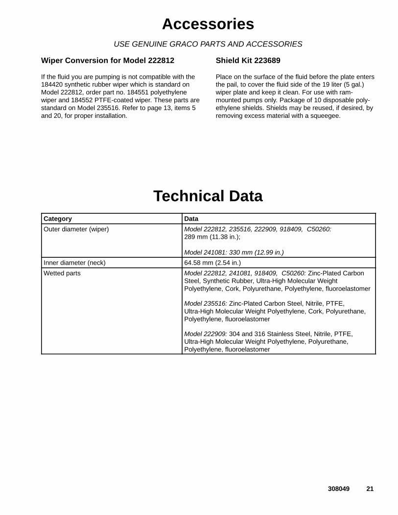
AccessoriesUSE GENUINE GRACO PARTS AND ACCESSORIES
Wiper Conversion for Model 222812
If the fluid you are pumping is not compatible with the184420 synthetic rubber wiper which is standard onModel 222812, order part no. 184551 polyethylenewiper and 184552 PTFE-coated wiper. These parts arestandard on Model 235516. Refer to page 13, items 5and 20, for proper installation.
Shield Kit 223689
Place on the surface of the fluid before the plate entersthe pail, to cover the fluid side of the 19 liter (5 gal.)wiper plate and keep it clean. For use with ram-mounted pumps only. Package of 10 disposable poly-ethylene shields. Shields may be reused, if desired, byremoving excess material with a squeegee.
Technical DataCategory Data
Outer diameter (wiper) Model 222812, 235516, 222909, 918409, C50260:289 mm (11.38 in.);
Model 241081: 330 mm (12.99 in.)
Inner diameter (neck) 64.58 mm (2.54 in.)
Wetted parts Model 222812, 241081, 918409, C50260: Zinc-Plated CarbonSteel, Synthetic Rubber, Ultra-High Molecular WeightPolyethylene, Cork, Polyurethane, Polyethylene, fluoroelastomer
Model 235516: Zinc-Plated Carbon Steel, Nitrile, PTFE,Ultra-High Molecular Weight Polyethylene, Cork, Polyurethane,Polyethylene, fluoroelastomer
Model 222909: 304 and 316 Stainless Steel, Nitrile, PTFE,Ultra-High Molecular Weight Polyethylene, Polyurethane,Polyethylene, fluoroelastomer

22 308049
Graco Standard WarrantyGraco warrants all equipment manufactured by Graco and bearing its name to be free from defects in material and workmanship on thedate of sale by an authorized Graco distributor to the original purchaser for use. With the exception of any special, extended, or limitedwarranty published by Graco, Graco will, for a period of twelve months from the date of sale, repair or replace any part of the equipmentdetermined by Graco to be defective. This warranty applies only when the equipment is installed, operated and maintained in accor-dance with Graco’s written recommendations.
This warranty does not cover, and Graco shall not be liable for general wear and tear, or any malfunction, damage or wear caused byfaulty installation, misapplication, abrasion, corrosion, inadequate or improper maintenance, negligence, accident, tampering, or sub-stitution of non--Graco component parts. Nor shall Graco be liable for malfunction, damage or wear caused by the incompatibility ofGraco equipment with structures, accessories, equipment or materials not supplied by Graco, or the improper design, manufacture,installation, operation or maintenance of structures, accessories, equipment or materials not supplied by Graco.
This warranty is conditioned upon the prepaid return of the equipment claimed to be defective to an authorized Graco distributor forverification of the claimed defect. If the claimed defect is verified, Graco will repair or replace free of charge any defective parts. Theequipment will be returned to the original purchaser transportation prepaid. If inspection of the equipment does notdisclose any defectin material or workmanship, repairs will be made at a reasonable charge, which charges may include the costs of parts, labor, andtransportation.
THIS WARRANTY IS EXCLUSIVE, AND IS IN LIEU OF ANY OTHER WARRANTIES, EXPRESS OR IMPLIED, INCLUDING BUTNOT LIMITED TO WARRANTY OF MERCHANTABILITY OR WARRANTY OF FITNESS FOR A PARTICULAR PURPOSE.
Graco’s sole obligation and buyer’s sole remedy for any breach of warranty shall be as set forth above. The buyer agrees that no otherremedy (including, but not limited to, incidental or consequential damages for lost profits, lost sales, injury to person or property, or anyother incidental or consequential loss) shall be available. Any action for breach of warranty must be brought within two (2) years of thedate of sale.
Graco makes no warranty, and disclaims all implied warranties of merchantability and fitness for a particular purpose in connectionwith accessories, equipment, materials or components sold but not manufactured by Graco. These items sold, but not manufacturedby Graco (such as electric motors, switches, hose, etc.), are subject to the warranty, if any, of their manufacturer. Graco will providepurchaser with reasonable assistance in making any claim for breach of these warranties.
In no event will Graco be liable for indirect, incidental, special or consequential damages resulting from Graco supplying equipmenthereunder, or the furnishing, performance, or use of any products or other goods sold hereto, whether due to a breach of contract,breach of warranty, the negligence of Graco, or otherwise.
FOR GRACO CANADA CUSTOMERSThe parties acknowledge that they have required that the present document, as well as all documents, notices and legal proceedingsentered into, given or instituted pursuant hereto or relating directly or indirectly hereto, be drawn up in English. Les parties reconnais-sent avoir convenu que la rédaction du présente document sera en Anglais, ainsi que tous documents, avis et procédures judiciairesexécutés, donnés ou intentés à la suite de ou en rapport, directement ou indirectement, avec les procedures concernées.
Graco InformationFor the latest information about Graco products, visit www.graco.com.
TO PLACE AN ORDER, contact your Graco distributor or call to identify the distributor closest to you:Phone: 612--623--6921 or Toll Free: 1--800--328--0211 Fax: 612--378--3505
All written and visual data contained in this document reflects the latest product information available at the time of publication.Graco reserves the right to make changes at any time without notice.
Original instructions. This manual contains English. MM 308049
Graco Headquarters: MinneapolisInternational Offices: Belgium, China, Japan, Korea
GRACO INC. AND SUBSIDIARIES P.O. BOX 1441 MINNEAPOLIS, MN 55440--1441 USACopyright 1990, Graco Inc. All Graco manufacturing locations are registered to ISO 9001
www.graco.comRevised June 2017