
300M series - SKS SWEDEN · 2018-03-05 · Group Type of protection Operating conditions I Group II...
17
PRODUCT 300M series Modular planetary gearboxes IE2-IE3
Transcript of 300M series - SKS SWEDEN · 2018-03-05 · Group Type of protection Operating conditions I Group II...

HEADQUARTERSBonfiglioli Riduttori S.p.A.Via Giovanni XXIII, 7/A40012 Lippo di Calderara di RenoBologna (Italy)tel: +39 051 647 3111fax: +39 051 647 [email protected]
We have a relentless commitment to excellence, innovation and sustainability. Our team creates, distributes and services world-class power transmission and drive solutions to keep the world in motion.
PRODUCT
300M seriesModular planetary gearboxes
300M
ser
ies
ENG
IE2-IE3

480 / 586
PLANETARY GEARBOX SERIES 300M ATEX CONFIGURATION
A1 SCOPE OF DOCUMENT
This Technical Bulletin serves as an aid for the selection of 300M series planetary gear units intended for installation in explosion risk areas, classifi ed according to Directive 1999/92/EC.
This Technical Bulletin is an integral part of the 300M series, and subsequent revisions, and has the following scope:“ describes the constructional characteristics of the reducers comply with the directive 2014/34/EU, where these differ from those of standard construction gear units - See section A4.2.“ specifi es the selection criteria approved by the manufacturer that said gear units operate keeping the minimum security requirements required by the Directive 2014/34/EU - See section A4.4.
A2 INTRODUCTION TO THE ATEX DIRECTIVES
Under the provisions of Directive 2014/34/EU, an explosive atmosphere is defi ned as a mixture:a) of fl ammable substances, whether gas, vapour, mist or dust;b) with air;c) in certain atmospheric conditions;d) in which, following ignition, combustion spreads to the entire unburned mixture (note that in the case of dust, the entire quantity of dust is not always completely burnt after combustion).An atmosphere which may potentially be transformed into an explosive atmosphere due to operating and/or ambient conditions is defi ned as a potentially explosive atmosphere. The products governed by Directive 2014/34/EU are intended for use only in a potentially explosive atmosphere defi ned in this way.
European harmonised ATEX standardsThe European Union has issued two harmonisation guidelines in the area of health and safety. Directive 2014/34/EU stipulates the minimum safety requirements for products intended for use in explosion risk areas within the member countries of the European Union. The directive also assigns such equipment to categories, which are defi ned by the directive itself.Directive 1999/92/EC defi nes the minimum health and safety requirements for the workplace, for working conditions and for the handling of products and materials in explosion risk areas. The directive also divides the workplace into zones and defi nes the criteria for the application of product categories in said zones.The following table describes the zones into which the user of a plant, in which an explosive atmosphere may occur, is required to divide the equipment application areas.
ZonesFormation frequency of a potentially explosive
atmosphere Type of dangerGaseousatmosphere
Dustyatmosphere
G D
0 20 Present continuously or for long periods Permanent
1 21 Likely to occur in normal operation occasionally Potential
2 22 Not likely to occur in normal operation but if it does occur will persist for short period only Minimal
Protection level
CategoryType of protection Operating conditionsGroup
IGroup
II
Very high M1Two independent means of protection or safety capable of operating even when two
independent faults occur
The equipment remains powered and operational even in the presence of an explosive
atmosphere
Very high 1Two independent means of protection or safety capable of operating even when two
independent faults occur
The equipment remains powered and operational in zones 0, 1, 2 (G)
and/or zones 20, 21, 22 (D)
High M2 Protection suitable for normal operation and heavy duty conditions
Power to the equipment is shut off in the presence of a potentially
explosive atmosphere
High 2Protection suitable for normal
operation and frequent faults or equipment in which malfunction is
normal.
The equipment remains powered and operational in zones 1, 2 (G)
and/or zones 21, 22 (D)
Normal 3 Protection suitable for normal operation
The equipment remains powered and operational in zones 2 (G) and/
or 22 (D)
BONFIGLIOLI RIDUTTORI gear units selected in this catalogue are suitable for installation in zones 1, 21, as highlighted in light gray in the above table, 2 and 22 only on request by contacting our Technical Department, highlighted in dark gray in the diagram above.Starting from July 1, 2003, the Atex Directives apply throughout the European Union, and replace the divergent laws currently in force at national and European level in the fi eld of explosive atmospheres.The directives apply to mechanical, hydraulic and pneumatic equipment.
Levels of protection for the various categories of equipmentThe various categories of equipment must be able to operate in conformity with the Manufacturer’s operational specifi cations, at certain defi ned levels of protection.
Defi nition of groups (EN 1127-1)Group I Applies to equipment intended for use underground in parts of mines and those parts of surface installations of such mines, liable to be endangered by fi redamp and/or combustible dust.Group II Applies to equipment intended for use in other places liable to be endangered by explosive atmospheres.
The areas highlighted in grey indicate the only categories in which BONFIGLIOLI RIDUTTORI products may be used. BONFIGLIOLI RIDUTTORI products may not therefore be installed in mines, classifi ed in Group I. To summarise, the classifi cation of equipment into groups, categories and zones is illustrated in the table below, where the availability of BONFIGLIOLI RIDUTTORI products is highlighted in grey.
Protection level
CategoryType of protection Operating conditionsGroup
IGroup
II
Very high M1Two independent means of protection or safety capable of operating even when two
independent faults occur
The equipment remains powered and operational even in the presence of an explosive
atmosphere
Very high 1Two independent means of protection or safety capable of operating even when two
independent faults occur
The equipment remains powered and operational in zones 0, 1, 2 (G)
and/or zones 20, 21, 22 (D)
High M2 Protection suitable for normal operation and heavy duty conditions
Power to the equipment is shut off in the presence of a potentially
explosive atmosphere
High 2Protection suitable for normal
operation and frequent faults or equipment in which malfunction is
normal.
The equipment remains powered and operational in zones 1, 2 (G)
and/or zones 21, 22 (D)
Normal 3 Protection suitable for normal operation
The equipment remains powered and operational in zones 2 (G) and/
or 22 (D)
Group I IImines, fi redamp other potentially explosive areas (gas, dust)
Category M1 M2 1 2 3Atmosphere(1) G D G D G D
Zone 0 20 1 21 2 22Type of protection
gear unit(2) c, k c, k c, k c, k
(1) G = gas D = DUST(2) as per EN13463

481 / 586
PLANETARY GEARBOX SERIES 300M ATEX CONFIGURATION
A1 SCOPE OF DOCUMENT
This Technical Bulletin serves as an aid for the selection of 300M series planetary gear units intended for installation in explosion risk areas, classifi ed according to Directive 1999/92/EC.
This Technical Bulletin is an integral part of the 300M series, and subsequent revisions, and has the following scope:“ describes the constructional characteristics of the reducers comply with the directive 2014/34/EU, where these differ from those of standard construction gear units - See section A4.2.“ specifi es the selection criteria approved by the manufacturer that said gear units operate keeping the minimum security requirements required by the Directive 2014/34/EU - See section A4.4.
A2 INTRODUCTION TO THE ATEX DIRECTIVES
Under the provisions of Directive 2014/34/EU, an explosive atmosphere is defi ned as a mixture:a) of fl ammable substances, whether gas, vapour, mist or dust;b) with air;c) in certain atmospheric conditions;d) in which, following ignition, combustion spreads to the entire unburned mixture (note that in the case of dust, the entire quantity of dust is not always completely burnt after combustion).An atmosphere which may potentially be transformed into an explosive atmosphere due to operating and/or ambient conditions is defi ned as a potentially explosive atmosphere. The products governed by Directive 2014/34/EU are intended for use only in a potentially explosive atmosphere defi ned in this way.
European harmonised ATEX standardsThe European Union has issued two harmonisation guidelines in the area of health and safety. Directive 2014/34/EU stipulates the minimum safety requirements for products intended for use in explosion risk areas within the member countries of the European Union. The directive also assigns such equipment to categories, which are defi ned by the directive itself.Directive 1999/92/EC defi nes the minimum health and safety requirements for the workplace, for working conditions and for the handling of products and materials in explosion risk areas. The directive also divides the workplace into zones and defi nes the criteria for the application of product categories in said zones.The following table describes the zones into which the user of a plant, in which an explosive atmosphere may occur, is required to divide the equipment application areas.
ZonesFormation frequency of a potentially explosive
atmosphere Type of dangerGaseousatmosphere
Dustyatmosphere
G D
0 20 Present continuously or for long periods Permanent
1 21 Likely to occur in normal operation occasionally Potential
2 22 Not likely to occur in normal operation but if it does occur will persist for short period only Minimal
Protection level
CategoryType of protection Operating conditionsGroup
IGroup
II
Very high M1Two independent means of protection or safety capable of operating even when two
independent faults occur
The equipment remains powered and operational even in the presence of an explosive
atmosphere
Very high 1Two independent means of protection or safety capable of operating even when two
independent faults occur
The equipment remains powered and operational in zones 0, 1, 2 (G)
and/or zones 20, 21, 22 (D)
High M2 Protection suitable for normal operation and heavy duty conditions
Power to the equipment is shut off in the presence of a potentially
explosive atmosphere
High 2Protection suitable for normal
operation and frequent faults or equipment in which malfunction is
normal.
The equipment remains powered and operational in zones 1, 2 (G)
and/or zones 21, 22 (D)
Normal 3 Protection suitable for normal operation
The equipment remains powered and operational in zones 2 (G) and/
or 22 (D)
BONFIGLIOLI RIDUTTORI gear units selected in this catalogue are suitable for installation in zones 1, 21, as highlighted in light gray in the above table, 2 and 22 only on request by contacting our Technical Department, highlighted in dark gray in the diagram above.Starting from July 1, 2003, the Atex Directives apply throughout the European Union, and replace the divergent laws currently in force at national and European level in the fi eld of explosive atmospheres.The directives apply to mechanical, hydraulic and pneumatic equipment.
Levels of protection for the various categories of equipmentThe various categories of equipment must be able to operate in conformity with the Manufacturer’s operational specifi cations, at certain defi ned levels of protection.
Defi nition of groups (EN 1127-1)Group I Applies to equipment intended for use underground in parts of mines and those parts of surface installations of such mines, liable to be endangered by fi redamp and/or combustible dust.Group II Applies to equipment intended for use in other places liable to be endangered by explosive atmospheres.
The areas highlighted in grey indicate the only categories in which BONFIGLIOLI RIDUTTORI products may be used. BONFIGLIOLI RIDUTTORI products may not therefore be installed in mines, classifi ed in Group I. To summarise, the classifi cation of equipment into groups, categories and zones is illustrated in the table below, where the availability of BONFIGLIOLI RIDUTTORI products is highlighted in grey.
Protection level
CategoryType of protection Operating conditionsGroup
IGroup
II
Very high M1Two independent means of protection or safety capable of operating even when two
independent faults occur
The equipment remains powered and operational even in the presence of an explosive
atmosphere
Very high 1Two independent means of protection or safety capable of operating even when two
independent faults occur
The equipment remains powered and operational in zones 0, 1, 2 (G)
and/or zones 20, 21, 22 (D)
High M2 Protection suitable for normal operation and heavy duty conditions
Power to the equipment is shut off in the presence of a potentially
explosive atmosphere
High 2Protection suitable for normal
operation and frequent faults or equipment in which malfunction is
normal.
The equipment remains powered and operational in zones 1, 2 (G)
and/or zones 21, 22 (D)
Normal 3 Protection suitable for normal operation
The equipment remains powered and operational in zones 2 (G) and/
or 22 (D)
Group I IImines, fi redamp other potentially explosive areas (gas, dust)
Category M1 M2 1 2 3Atmosphere(1) G D G D G D
Zone 0 20 1 21 2 22Type of protection
gear unit(2) c, k c, k c, k c, k
(1) G = gas D = DUST(2) as per EN13463

482 / 586
A3 USE, INSTALLATION AND MAINTENANCE
The instructions for safe storage, handling and use of the product are given in the unit’s User, Installation and Service Manual.This document must be kept in a suitable place, in the vicinity of the installed gear unit, as a reference for all persons authorised to work with or on the product throughout its service life.
The Manufacturer reserves the right to modify, supplement or improve the Manual, in the interests of the User.
3...L 3...R 3/V300...309,
310M...318M, 319 L 1 - - - - - -
300...309, 310M...318M, 319...321 L 2 300...306 R 2 - - -
300...309, 310M...318M, 319...321 L 3 300...309, 310M...317M R 3 300...306 L 3
300...309, 310M...318M, 319...325 L 4 300...309, 310M...318M,
319...321 R 4 - - -
Confi gurations
VersionsFoot mount Flange mount Shaft mount Agitator
(vertical)
PC PZ MC/HC MZ/HZ FZ FP FDK FZP VK
Inputs
P(IEC) V_
Standard negativemultidisc brake6 = Type: 4, 5, 6A = Braking torque: A, B, C, ...
Hydraulic motor connecting
NOTE:- With the negative multi disc brake, you must always ensure a minimum pressure for opening the discs. This must be 20% higher than that of the table of the brakes.- The pressure max. of brake control must not exceed 50 bar.
Accessories
P ... B0A M0A G0A W0A
A4 PECULIARITIES OF 300M SERIES GEAR UNITS COMPLIANT WITH DIRECTIVE ATEX
A4.1 PRODUCT AVAILABILITY
Frame sizes : 300 to 325.
3...L 3...R 3/V300...309,
310M...318M, 319 L 1 - - - - - -
300...309, 310M...318M, 319...321 L 2 300...306 R 2 - - -
300...309, 310M...318M, 319...321 L 3 300...309, 310M...317M R 3 300...306 L 3
300...309, 310M...318M, 319...325 L 4 300...309, 310M...318M,
319...321 R 4 - - -
Confi gurations
A4.2 CONSTRUCTIONAL CHARACTERISTICS
• Only synthetic lubricants are used.• Only VITON® gaskets are used.• Oil seals are equipped with dust lips.• Vent plugs are equipped with valves with anti-intrusion springs, to prevent contamination of the lubricant by solid particles.• Oil fi ller, drain and level plugs are made from steel and equipped with aluminium lock washers.• No external metal moving parts in contact with other parts.• No plastic parts prone to accumulating static charges; if present, such parts are shielded.• Each gear unit is supplied with an installation drawing indicating the following information:- main technical characteristics- installation specifi cations- location of oil plugs for the specifi ed mounting position- lubrication instructions• The units are fi tted with an additional nameplate specifying the product category. For example:
A4.3 OPERATIONAL CHARACTERISTICS
For installation in zones 21 and 22, the Customer must set out and implement a specifi c cleaning schedule for the unit’s surfaces and recesses to prevent build ups of dust exceeding 5 mm in depth.
TUV IT 15 ATEX 001 AR
2014/34/UE
483 / 586
A3 USE, INSTALLATION AND MAINTENANCE
The instructions for safe storage, handling and use of the product are given in the unit’s User, Installation and Service Manual.This document must be kept in a suitable place, in the vicinity of the installed gear unit, as a reference for all persons authorised to work with or on the product throughout its service life.
The Manufacturer reserves the right to modify, supplement or improve the Manual, in the interests of the User.
3...L 3...R 3/V300...309,
310M...318M, 319 L 1 - - - - - -
300...309, 310M...318M, 319...321 L 2 300...306 R 2 - - -
300...309, 310M...318M, 319...321 L 3 300...309, 310M...317M R 3 300...306 L 3
300...309, 310M...318M, 319...325 L 4 300...309, 310M...318M,
319...321 R 4 - - -
Confi gurations
VersionsFoot mount Flange mount Shaft mount Agitator
(vertical)
PC PZ MC/HC MZ/HZ FZ FP FDK FZP VK
Inputs
P(IEC) V_
Standard negativemultidisc brake6 = Type: 4, 5, 6A = Braking torque: A, B, C, ...
Hydraulic motor connecting
NOTE:- With the negative multi disc brake, you must always ensure a minimum pressure for opening the discs. This must be 20% higher than that of the table of the brakes.- The pressure max. of brake control must not exceed 50 bar.
Accessories
P ... B0A M0A G0A W0A
A4 PECULIARITIES OF 300M SERIES GEAR UNITS COMPLIANT WITH DIRECTIVE ATEX
A4.1 PRODUCT AVAILABILITY
Frame sizes : 300 to 325.
3...L 3...R 3/V300...309,
310M...318M, 319 L 1 - - - - - -
300...309, 310M...318M, 319...321 L 2 300...306 R 2 - - -
300...309, 310M...318M, 319...321 L 3 300...309, 310M...317M R 3 300...306 L 3
300...309, 310M...318M, 319...325 L 4 300...309, 310M...318M,
319...321 R 4 - - -
Confi gurations
A4.2 CONSTRUCTIONAL CHARACTERISTICS
• Only synthetic lubricants are used.• Only VITON® gaskets are used.• Oil seals are equipped with dust lips.• Vent plugs are equipped with valves with anti-intrusion springs, to prevent contamination of the lubricant by solid particles.• Oil fi ller, drain and level plugs are made from steel and equipped with aluminium lock washers.• No external metal moving parts in contact with other parts.• No plastic parts prone to accumulating static charges; if present, such parts are shielded.• Each gear unit is supplied with an installation drawing indicating the following information:- main technical characteristics- installation specifi cations- location of oil plugs for the specifi ed mounting position- lubrication instructions• The units are fi tted with an additional nameplate specifying the product category. For example:
A4.3 OPERATIONAL CHARACTERISTICS
For installation in zones 21 and 22, the Customer must set out and implement a specifi c cleaning schedule for the unit’s surfaces and recesses to prevent build ups of dust exceeding 5 mm in depth.
TUV IT 15 ATEX 001 AR
2014/34/UE

484 / 586
A4.4 SELECTING THE PRODUCT
The gear unit and gearmotor selection procedure is identical to that given in the 300M Series, and any future revisions thereof.The following chapters contain variations to the procedure given in the catalogue, and subsequent revisions thereof as regards the selection of products compliant with 2014/34/EU, which supersede the procedure specifi ed in the catalogue for units intended for installation in areas without risk of explosion.These variations primarily affect the following:• Application of an adjusting factor to the thermal capacity.• Application of a service factor « fs » with a greater safety margin.
- Thermal capacity « Pt » [kW]This parameter is linked to the gearbox thermal limit. Values for the thermal capacity are listed within the rating charts of gearboxes and gearmotors and represent the mechanical power that can be transmitted continuously at an input speed n1 and at an ambient temperature of 20°C, without the temperatures to and ts exceeding the values indicated in the chapter “Allowed temperature limits”.When the duty cycle is formed by short operating periods and rest time is long enough for the unit to cool down, the thermal capacity is hardly signifi cant and it may be omitted from calculation.For ambient temperatures other than 20°C, intermittent duty and drive speed n1 other than the reference speed listed in the rating charts, Pt is to be adjusted through thermal factor ft and/or speed factor fv as listed in the following tables. Finally, make sure that the following condition is always satisfi ed:
fEX
300...309, 310M...318M, 319...321 L - 1 0.8300...309, 310M...318M, 319...321 L - 2 0.9300...309, 310M...318M, 319...321 L - 3 - 4 1.0
300...306 - R 2 0.8300...309, 310M...318M, 319...321 - R 3 - 4 0.9
ft
ta
(°C)
80% 60% 40% 20%
10 1.2 1.3 1.6 1.8 2.020 1.0 1.1 1.3 1.5 1.730 0.9 1.0 1.2 1.3 1.540 0.7 0.8 0.9 1.0 1.250 0.5 0.6 0.7 0.8 0.9
n1 (min-1) fv
500 1.35900 1.2
1500 1.01800 0.85
Continuous duty
Intermittent duty
Intermittence ratio« I »
Frame sizeConfi guration
reductionsin line right angle
Pr1 ≤ Pt x ft x fv x fEx
I =t
t tf
f r
x 100 tf = operating time under load;tr = rest time.
- Service factor in Atex gearboxes with Negative multidisc brake
100 200 300 400 500 600 700 800 900 1000 1100 1200 1300 1400 1500 1600 1700 1800
300
L1L2 85%L3 85%L4 85%
301
L1L2 85%L3 85%L4 85%
303
L1 85%L2 85%L3 85%L4 85%
305
L1 85%L2 85%L3 85%L4 85%
306
L1 85%L2 85% 75%L3 85%L4 85%
307
L1 85%L2 85% 75%L3 85%L4 85%
309
L1 85%L2 85% 75%L3 85%L4 85%
310M
L1 no brakeL2 85%L3 85% 75%L4 85%
311M
L1 no brakeL2 85%L3 85% 75%L4 85%
313M
L1 no brakeL2 85%L3 85% 75%L4 85%
315M
L1 no brakeL2L3 85% 80%L4 85% 75%
316M
L1 no brakeL2 no brakeL3 85% 80%L4 85% 75%
317M
L1 no brakeL2 no brakeL3 85%L4 85% 75%
318M
L1 no brakeL2 no brakeL3 85% 80%L4 85% 75%
319
L1 no brakeL2 no brakeL3 85%L4 85% 80%
321
L1 no brakeL2 no brakeL3 no brakeL4 85% 80%
POS A, E, F, G Input speed [rpm]
Unusable speed

485 / 586
A4.4 SELECTING THE PRODUCT
The gear unit and gearmotor selection procedure is identical to that given in the 300M Series, and any future revisions thereof.The following chapters contain variations to the procedure given in the catalogue, and subsequent revisions thereof as regards the selection of products compliant with 2014/34/EU, which supersede the procedure specifi ed in the catalogue for units intended for installation in areas without risk of explosion.These variations primarily affect the following:• Application of an adjusting factor to the thermal capacity.• Application of a service factor « fs » with a greater safety margin.
- Thermal capacity « Pt » [kW]This parameter is linked to the gearbox thermal limit. Values for the thermal capacity are listed within the rating charts of gearboxes and gearmotors and represent the mechanical power that can be transmitted continuously at an input speed n1 and at an ambient temperature of 20°C, without the temperatures to and ts exceeding the values indicated in the chapter “Allowed temperature limits”.When the duty cycle is formed by short operating periods and rest time is long enough for the unit to cool down, the thermal capacity is hardly signifi cant and it may be omitted from calculation.For ambient temperatures other than 20°C, intermittent duty and drive speed n1 other than the reference speed listed in the rating charts, Pt is to be adjusted through thermal factor ft and/or speed factor fv as listed in the following tables. Finally, make sure that the following condition is always satisfi ed:
fEX
300...309, 310M...318M, 319...321 L - 1 0.8300...309, 310M...318M, 319...321 L - 2 0.9300...309, 310M...318M, 319...321 L - 3 - 4 1.0
300...306 - R 2 0.8300...309, 310M...318M, 319...321 - R 3 - 4 0.9
ft
ta
(°C)
80% 60% 40% 20%
10 1.2 1.3 1.6 1.8 2.020 1.0 1.1 1.3 1.5 1.730 0.9 1.0 1.2 1.3 1.540 0.7 0.8 0.9 1.0 1.250 0.5 0.6 0.7 0.8 0.9
n1 (min-1) fv
500 1.35900 1.2
1500 1.01800 0.85
Continuous duty
Intermittent duty
Intermittence ratio« I »
Frame sizeConfi guration
reductionsin line right angle
Pr1 ≤ Pt x ft x fv x fEx
I =t
t tf
f r
x 100 tf = operating time under load;tr = rest time.
- Service factor in Atex gearboxes with Negative multidisc brake
100 200 300 400 500 600 700 800 900 1000 1100 1200 1300 1400 1500 1600 1700 1800
300
L1L2 85%L3 85%L4 85%
301
L1L2 85%L3 85%L4 85%
303
L1 85%L2 85%L3 85%L4 85%
305
L1 85%L2 85%L3 85%L4 85%
306
L1 85%L2 85% 75%L3 85%L4 85%
307
L1 85%L2 85% 75%L3 85%L4 85%
309
L1 85%L2 85% 75%L3 85%L4 85%
310M
L1 no brakeL2 85%L3 85% 75%L4 85%
311M
L1 no brakeL2 85%L3 85% 75%L4 85%
313M
L1 no brakeL2 85%L3 85% 75%L4 85%
315M
L1 no brakeL2L3 85% 80%L4 85% 75%
316M
L1 no brakeL2 no brakeL3 85% 80%L4 85% 75%
317M
L1 no brakeL2 no brakeL3 85%L4 85% 75%
318M
L1 no brakeL2 no brakeL3 85% 80%L4 85% 75%
319
L1 no brakeL2 no brakeL3 85%L4 85% 80%
321
L1 no brakeL2 no brakeL3 no brakeL4 85% 80%
POS A, E, F, G Input speed [rpm]
Unusable speed
486 / 586
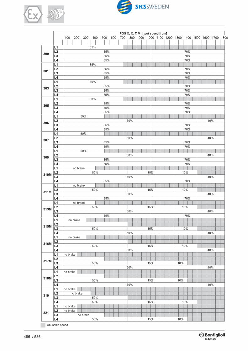
100 200 300 400 500 600 700 800 900 1000 1100 1200 1300 1400 1500 1600 1700 1800
300
L1 85%L2 85% 70% L3 85% 70%L4 85% 70%
301
L1 85%L2 85% 70%L3 85% 70%L4 85% 70%
303
L1 60%L2 85% 70%L3 85% 70%L4 85% 70%
305
L1 60%L2 85% 70%L3 85% 70%L4 85% 70%
306
L1 50%L2 60% 40%L3 85% 70%L4 85% 70%
307
L1 50%L2 60% 40%L3 85% 70%L4 85% 70%
309
L1 50%L2 60% 40%L3 85% 70%L4 85% 70%
310M
L1 no brakeL2 50% 15% 10%L3 60% 40%L4 85% 70%
311M
L1 no brakeL2 50% 15% 10%L3 60% 40%L4 85% 70%
313M
L1 no brakeL2 50% 15% 10%L3 60% 40%L4 85% 70%
315M
L1 no brakeL2L3 50% 15% 10%L4 60% 40%
316M
L1 no brakeL2L3 50% 15% 10%L4 60% 40%
317M
L1 no brakeL2L3 50% 15% 10%L4 60% 40%
318M
L1 no brakeL2L3 50% 15% 10%L4 60% 40%
319
L1 no brakeL2 no brakeL3 50%L4 50% 15% 10%
321
L1 no brakeL2 no brakeL3 no brakeL4 50% 15% 10%
POS O, Q, T, V Input speed [rpm]
Unusable speed
100 200 300 400 500 600 700 800 900 1000 1100 1200 1300 1400 1500 1600 1700 1800
300R2 85% 70%R3 85% 70%R4 85% 70%
301R2 85% 70%R3 85% 70%R4 85% 70%
303R2 85% 70%R3 85% 70%R4 85% 70%
305R2 85% 70%R3 85% 70%R4 85% 70%
306R2 85% 70%R3 85% 70%R4 85% 70%
307R2 60% 40%R3 85% 70%R4 85% 70%
309R2 60% 40%R3 85% 70%R4 85% 70%
310M
R2 (A) 60% 40%R2 (B) 50% 15% 10%R3 85% 70%R4 85% 70%
311M
R2 (A) 60% 40%R2 (B) 50% 15% 10%R2 (C) 50% 15% 10%R3 60% 40%R4 85% 70%
313M
R2 (A) 60%R2 (B) 50% 15% 10%R2 (C) 50% 15% 10%R3 60% 40%R4 85% 70%
315M
R3 (A) 60%R3 (B) 50% 15% 10%R3 (C) 50% 15% 10%R4 60% 40%
316MR3 (B) 50% 15% 10%R3 (C) 50% 15% 10%R4 60% 40%
317M
R3 (A) 60%R3 (B) 50% 15% 10%R3 (C) 50% 15% 10%R4 60% 40%
318M R4 (B) 50% 15% 10%R4 (C) 50% 15% 10%
319R4 (B) 60%R4 (C) 50% 15% 10%R4 (C) 50% 15% 10%
321R4 (B) 60%R4 (C) 50% 15% 10%R4 (C) 50% 15% 10%
Unusable speed
POS B0, B2, I0, I2, J0, J2, M1, M3, P, R, U, W Input speed [rpm]

487 / 586
100 200 300 400 500 600 700 800 900 1000 1100 1200 1300 1400 1500 1600 1700 1800
300
L1 85%L2 85% 70% L3 85% 70%L4 85% 70%
301
L1 85%L2 85% 70%L3 85% 70%L4 85% 70%
303
L1 60%L2 85% 70%L3 85% 70%L4 85% 70%
305
L1 60%L2 85% 70%L3 85% 70%L4 85% 70%
306
L1 50%L2 60% 40%L3 85% 70%L4 85% 70%
307
L1 50%L2 60% 40%L3 85% 70%L4 85% 70%
309
L1 50%L2 60% 40%L3 85% 70%L4 85% 70%
310M
L1 no brakeL2 50% 15% 10%L3 60% 40%L4 85% 70%
311M
L1 no brakeL2 50% 15% 10%L3 60% 40%L4 85% 70%
313M
L1 no brakeL2 50% 15% 10%L3 60% 40%L4 85% 70%
315M
L1 no brakeL2L3 50% 15% 10%L4 60% 40%
316M
L1 no brakeL2L3 50% 15% 10%L4 60% 40%
317M
L1 no brakeL2L3 50% 15% 10%L4 60% 40%
318M
L1 no brakeL2L3 50% 15% 10%L4 60% 40%
319
L1 no brakeL2 no brakeL3 50%L4 50% 15% 10%
321
L1 no brakeL2 no brakeL3 no brakeL4 50% 15% 10%
POS O, Q, T, V Input speed [rpm]
Unusable speed
100 200 300 400 500 600 700 800 900 1000 1100 1200 1300 1400 1500 1600 1700 1800
300R2 85% 70%R3 85% 70%R4 85% 70%
301R2 85% 70%R3 85% 70%R4 85% 70%
303R2 85% 70%R3 85% 70%R4 85% 70%
305R2 85% 70%R3 85% 70%R4 85% 70%
306R2 85% 70%R3 85% 70%R4 85% 70%
307R2 60% 40%R3 85% 70%R4 85% 70%
309R2 60% 40%R3 85% 70%R4 85% 70%
310M
R2 (A) 60% 40%R2 (B) 50% 15% 10%R3 85% 70%R4 85% 70%
311M
R2 (A) 60% 40%R2 (B) 50% 15% 10%R2 (C) 50% 15% 10%R3 60% 40%R4 85% 70%
313M
R2 (A) 60%R2 (B) 50% 15% 10%R2 (C) 50% 15% 10%R3 60% 40%R4 85% 70%
315M
R3 (A) 60%R3 (B) 50% 15% 10%R3 (C) 50% 15% 10%R4 60% 40%
316MR3 (B) 50% 15% 10%R3 (C) 50% 15% 10%R4 60% 40%
317M
R3 (A) 60%R3 (B) 50% 15% 10%R3 (C) 50% 15% 10%R4 60% 40%
318M R4 (B) 50% 15% 10%R4 (C) 50% 15% 10%
319R4 (B) 60%R4 (C) 50% 15% 10%R4 (C) 50% 15% 10%
321R4 (B) 60%R4 (C) 50% 15% 10%R4 (C) 50% 15% 10%
Unusable speed
POS B0, B2, I0, I2, J0, J2, M1, M3, P, R, U, W Input speed [rpm]

488 / 586
100 200 300 400 500 600 700 800 900 1000 1100 1200 1300 1400 1500 1600 1700 1800
300R2 85%R3 85%R4 85%
301R2 85%R3 85%R4 85%
303R2 85%R3 85%R4 85%
305R2 85%R3 85%R4 85%
306R2 85%R3 85%R4 85%
307R2 85% 75%R3 85%R4 85%
309R2 85% 75%R3 85%R4 85%
310M
R2 (A) 85% 75%R2 (B) 85%R3 85%R4 85%
311M
R2 (A) 85% 75%R2 (B) 85%R2 (C) 85%R3 85% 75%R4 85%
313M
R2 (A) 60%R2 (B) 85%R2 (C) 85%R3 85% 75%R4 85%
315M
R3 (A) 60%R3 (B) 85%R3 (C) 85%R4 85% 75%
316MR3 (B) 85%R3 (C) 85%R4 85% 75%
317M
R3 (A) 85%R3 (B) 85%R3 (C) 85%R4 85% 75%
318M R4 (B) 85%R4 (C) 85%
319R4 (B) 60%R4 (C) 85%R4 (C) 85%
321R4 (B) 85%R4 (C) 85%R4 (C) 85%
Unusable speed
POS B1, B3, I1, I3, J1, J3, M0, M2 Input speed [rpm] - Service factor « fs »
≤ 5000 10000 15000 25000 50000
h < 4 4 < h < 8 8 < h < 12 12 < h < 16 16 < h < 24
Z < 10 1.10 1.10 1.15 1.30 1.60
10 < Z < 30 1.10 1.15 1.30 1.50 1.80
30 < Z < 100 1.10 1.25 1.45 1.60 2.00
Z < 10 1.10 1.25 1.45 1.60 2.00
10 < Z < 30 1.10 1.40 1.60 1.80 2.20
30 < Z < 100 1.20 1.50 1.70 2.00 2.40
Z < 10 1.20 1.50 1.70 2.00 2.40
10 < Z < 30 1.30 1.60 1.80 2.10 2.60
30 < Z < 100 1.40 1.75 2.00 2.30 2.80
Service factor « fs »
Duty
Starts / hour
z
Accumulated operating hours (h)
Daily operating hours (h)
Uniform load
Moderate shock load
Heavy shock load
- Limitation of input speed for single-stage (L1) gearboxes
300 , 301 L1 1000
303 , 305 L1 700
306 ... 309 L1 500
310M ... 313M L1 400
315M , 316M L1 300
317M , 318M , 319 ... 321 L1 200
Frame size reductions n1 (min-1) MAX

489 / 586
100 200 300 400 500 600 700 800 900 1000 1100 1200 1300 1400 1500 1600 1700 1800
300R2 85%R3 85%R4 85%
301R2 85%R3 85%R4 85%
303R2 85%R3 85%R4 85%
305R2 85%R3 85%R4 85%
306R2 85%R3 85%R4 85%
307R2 85% 75%R3 85%R4 85%
309R2 85% 75%R3 85%R4 85%
310M
R2 (A) 85% 75%R2 (B) 85%R3 85%R4 85%
311M
R2 (A) 85% 75%R2 (B) 85%R2 (C) 85%R3 85% 75%R4 85%
313M
R2 (A) 60%R2 (B) 85%R2 (C) 85%R3 85% 75%R4 85%
315M
R3 (A) 60%R3 (B) 85%R3 (C) 85%R4 85% 75%
316MR3 (B) 85%R3 (C) 85%R4 85% 75%
317M
R3 (A) 85%R3 (B) 85%R3 (C) 85%R4 85% 75%
318M R4 (B) 85%R4 (C) 85%
319R4 (B) 60%R4 (C) 85%R4 (C) 85%
321R4 (B) 85%R4 (C) 85%R4 (C) 85%
Unusable speed
POS B1, B3, I1, I3, J1, J3, M0, M2 Input speed [rpm] - Service factor « fs »
≤ 5000 10000 15000 25000 50000
h < 4 4 < h < 8 8 < h < 12 12 < h < 16 16 < h < 24
Z < 10 1.10 1.10 1.15 1.30 1.60
10 < Z < 30 1.10 1.15 1.30 1.50 1.80
30 < Z < 100 1.10 1.25 1.45 1.60 2.00
Z < 10 1.10 1.25 1.45 1.60 2.00
10 < Z < 30 1.10 1.40 1.60 1.80 2.20
30 < Z < 100 1.20 1.50 1.70 2.00 2.40
Z < 10 1.20 1.50 1.70 2.00 2.40
10 < Z < 30 1.30 1.60 1.80 2.10 2.60
30 < Z < 100 1.40 1.75 2.00 2.30 2.80
Service factor « fs »
Duty
Starts / hour
z
Accumulated operating hours (h)
Daily operating hours (h)
Uniform load
Moderate shock load
Heavy shock load
- Limitation of input speed for single-stage (L1) gearboxes
300 , 301 L1 1000
303 , 305 L1 700
306 ... 309 L1 500
310M ... 313M L1 400
315M , 316M L1 300
317M , 318M , 319 ... 321 L1 200
Frame size reductions n1 (min-1) MAX

490 / 586
OUTPUT VERSION
GEAR RATIO
REDUCTIONS
DESIGN
SERIES
GEARBOX FRAME SIZE
Fill in the value of the gear ratio (including point and decimals) as listed in the selection chartsEx.: 1/44.6 = 44.6 1/131 = 131
L = In line R = Right angle
FP: Hollow shaft for shrink disc
FZP: Hollow splined shaft with axial blockage device (recommended for shaft mounted installation)
FDK: Hollow shaft with double keyway
MZ: Splined male shaft
HZ: Heavy duty splined male shaft
PZ: Foot base with splined shaft
FZ / FZB: Hollow splined shaft
MC: Solid keyed shaft
HC: Heavy duty solid keyed shaft
PC: Foot base with solid keyed shaft
VK: Reinforced output with heavy duty keyed shaft for stirrers and mixer
1 - 2 - 3 - 4
00 = 300 06 = 306 11M = 311M 17M = 317M 23 = 32501 = 301 07 = 307 13M = 313M 18M = 318M 25 = 32503 = 303 09 = 309 15M = 315M 19 = 31905 = 305 10M = 310M 16M = 316M 21 = 321
3 11M L HZ2 16.7
A5 ORDERING NUMBERS
A5.1 DESIGNATION OF IN-LINE (300M L) AND RIGHT ANGLE (300M R) GEAR UNITS OPTIONS
CONFIGURATION COMPLIANT WITH THE OLD DIRECTIVE94/9/EC AND AT THE NEW DIRECTIVE 2014/34/EU.
OUTPUT FITTINGS
MOUNTING POSITION
MOTOR FLANGE ORIENTATION
INPUT
ONLY WITH HYDRAULIC MOTOR ADAPTOR
RA = counterclockwiseRO = clockwise
INPUT SHAFT PREFERENTIAL DIRECTION OF ROTATION(applicable to angle gear units only)
Electric motor connection P + motor size (80,90,100,132,160, ...)
Standard negative multidisc brake
Negative multidisc brake for MG hydraulic motorSF = Without brake
6 = Type: 4, 5, 6A = Braking torque: A, B, C, ...
Hydraulic Motor connection
B0A = Splined bar
G0A = Shrink disc
M0A = Sleeve couplingP... = Pinions
W0A = Flange
In mounting positions featuring a vertical output shaft, the gearbox will be equip-
ped with an expansion tank.Please request the installation drawing to
Bonfi glioli’s Technical Service.
Input keyed shaft
V01A V01B V05B V06B V07A V07B V10B V11B V15B
diam. Ø24 Ø38 Ø48 Ø60 Ø60 Ø80 Ø80 Ø80 Ø120
- A A W0AV11B EX ...

491 / 586
OUTPUT VERSION
GEAR RATIO
REDUCTIONS
DESIGN
SERIES
GEARBOX FRAME SIZE
Fill in the value of the gear ratio (including point and decimals) as listed in the selection chartsEx.: 1/44.6 = 44.6 1/131 = 131
L = In line R = Right angle
FP: Hollow shaft for shrink disc
FZP: Hollow splined shaft with axial blockage device (recommended for shaft mounted installation)
FDK: Hollow shaft with double keyway
MZ: Splined male shaft
HZ: Heavy duty splined male shaft
PZ: Foot base with splined shaft
FZ / FZB: Hollow splined shaft
MC: Solid keyed shaft
HC: Heavy duty solid keyed shaft
PC: Foot base with solid keyed shaft
VK: Reinforced output with heavy duty keyed shaft for stirrers and mixer
1 - 2 - 3 - 4
00 = 300 06 = 306 11M = 311M 17M = 317M 23 = 32501 = 301 07 = 307 13M = 313M 18M = 318M 25 = 32503 = 303 09 = 309 15M = 315M 19 = 31905 = 305 10M = 310M 16M = 316M 21 = 321
3 11M L HZ2 16.7
A5 ORDERING NUMBERS
A5.1 DESIGNATION OF IN-LINE (300M L) AND RIGHT ANGLE (300M R) GEAR UNITS OPTIONS
CONFIGURATION COMPLIANT WITH THE OLD DIRECTIVE94/9/EC AND AT THE NEW DIRECTIVE 2014/34/EU.
OUTPUT FITTINGS
MOUNTING POSITION
MOTOR FLANGE ORIENTATION
INPUT
ONLY WITH HYDRAULIC MOTOR ADAPTOR
RA = counterclockwiseRO = clockwise
INPUT SHAFT PREFERENTIAL DIRECTION OF ROTATION(applicable to angle gear units only)
Electric motor connection P + motor size (80,90,100,132,160, ...)
Standard negative multidisc brake
Negative multidisc brake for MG hydraulic motorSF = Without brake
6 = Type: 4, 5, 6A = Braking torque: A, B, C, ...
Hydraulic Motor connection
B0A = Splined bar
G0A = Shrink disc
M0A = Sleeve couplingP... = Pinions
W0A = Flange
In mounting positions featuring a vertical output shaft, the gearbox will be equip-
ped with an expansion tank.Please request the installation drawing to
Bonfi glioli’s Technical Service.
Input keyed shaft
V01A V01B V05B V06B V07A V07B V10B V11B V15B
diam. Ø24 Ø38 Ø48 Ø60 Ø60 Ø80 Ø80 Ø80 Ø120
- A A W0AV11B EX ...

492 / 586
A5.2 DESIGNATION OF COMBINED WORM+PLANETARY (3/V) GEAR UNITS
INPUT SHAFT PREFERENTIAL DIRECTION OF ROTATION(applicable to angle gear units only)
GEAR RATIO
REDUCTIONS
DESIGN
SERIES
GEARBOX FRAME SIZE
Fill in the value of the gear ratio (including point and decimals) as listed in the selection chartsEx.: 1/773 = 773
3
L = Combined 300 unit, 2 planetary stages + worm gear units
Combined 300 gearboxes / Worm gear units
00 = 3/V 00 06 = 3/V 0601 = 3/V 0103 = 3/V 03 05 = 3/V 05
3/V3/V 05 L PC3 623
OUTPUT VERSION
FP: Hollow shaft for shrink disc
FZP: Hollow splined shaft with axial blockage device (recommended for shaft mounted installation)
FDK: Hollow shaft with double keyway
MZ: Splined male shaft
HZ: Heavy duty splined male shaft
PZ: Foot base with splined shaft
FZ / FZB: Hollow splined shaft
MC: Solid keyed shaft
HC: Heavy duty solid keyed shaft
PC: Foot base with solid keyed shaft
VK: Reinforced output with heavy duty keyed shaft for stirrers and mixer
CONFIGURATION COMPLIANT WITH THE DIRECTIVE 2014/34/EU.
OUTPUT FITTINGS
MOUNTING POSITION
MOTOR EXECUTION
INPUT
Input keyed shaftHS
Electric motor connectionP + motor size (80,90,100,132,160, ...)
P80 B5 AF W0A EX
B5, B14
B0A = Splined bar
G0A = Shrink disc
M0A = Sleeve couplingP... = Pinions
W0A = Flange

493 / 586
A5.2 DESIGNATION OF COMBINED WORM+PLANETARY (3/V) GEAR UNITS
INPUT SHAFT PREFERENTIAL DIRECTION OF ROTATION(applicable to angle gear units only)
GEAR RATIO
REDUCTIONS
DESIGN
SERIES
GEARBOX FRAME SIZE
Fill in the value of the gear ratio (including point and decimals) as listed in the selection chartsEx.: 1/773 = 773
3
L = Combined 300 unit, 2 planetary stages + worm gear units
Combined 300 gearboxes / Worm gear units
00 = 3/V 00 06 = 3/V 0601 = 3/V 0103 = 3/V 03 05 = 3/V 05
3/V3/V 05 L PC3 623
OUTPUT VERSION
FP: Hollow shaft for shrink disc
FZP: Hollow splined shaft with axial blockage device (recommended for shaft mounted installation)
FDK: Hollow shaft with double keyway
MZ: Splined male shaft
HZ: Heavy duty splined male shaft
PZ: Foot base with splined shaft
FZ / FZB: Hollow splined shaft
MC: Solid keyed shaft
HC: Heavy duty solid keyed shaft
PC: Foot base with solid keyed shaft
VK: Reinforced output with heavy duty keyed shaft for stirrers and mixer
CONFIGURATION COMPLIANT WITH THE DIRECTIVE 2014/34/EU.
OUTPUT FITTINGS
MOUNTING POSITION
MOTOR EXECUTION
INPUT
Input keyed shaftHS
Electric motor connectionP + motor size (80,90,100,132,160, ...)
P80 B5 AF W0A EX
B5, B14
B0A = Splined bar
G0A = Shrink disc
M0A = Sleeve couplingP... = Pinions
W0A = Flange

494 / 586
A6 DECLARATION OF CONFORMITY
The Declaration of Conformity, is the document which attests to the conformity of the product to Directive 2014/34/EU.The validity of the Declaration is bound to observance of the instructions given in the User, Installation and Service Manual for safe use of the product throughout its service life.This can be downloaded from www.bonfi glioli.com where the manual is available in PDF format in a number of languages.The instructions regarding ambient conditions are of particular importance inasmuch as failure to observe them during operation of the product renders the certifi cate null and void. In case of doubt regarding the validity of the certifi cate of conformity, contact the BONFIGLIOLI RIDUTTORI technical department.

495 / 586
A6 DECLARATION OF CONFORMITY
The Declaration of Conformity, is the document which attests to the conformity of the product to Directive 2014/34/EU.The validity of the Declaration is bound to observance of the instructions given in the User, Installation and Service Manual for safe use of the product throughout its service life.This can be downloaded from www.bonfi glioli.com where the manual is available in PDF format in a number of languages.The instructions regarding ambient conditions are of particular importance inasmuch as failure to observe them during operation of the product renders the certifi cate null and void. In case of doubt regarding the validity of the certifi cate of conformity, contact the BONFIGLIOLI RIDUTTORI technical department.