30 th June 2004Daniel Bowerman1 Dan Bowerman Imperial College LCUK Meeting - Lancaster 30 th June...
35
30 th June 2004 Daniel Bowerman 1 Dan Bowerman Imperial College LCUK Meeting - Lancaster 30 th June 2004 Calice Status For the CALICE-UK groups: Birmingham, Cambridge, Imperial, Manchester, RAL, UCL
-
date post
20-Dec-2015 -
Category
Documents
-
view
213 -
download
0
Transcript of 30 th June 2004Daniel Bowerman1 Dan Bowerman Imperial College LCUK Meeting - Lancaster 30 th June...

30th June 2004 Daniel Bowerman 1
Dan BowermanImperial College
LCUK Meeting - Lancaster30th June 2004
Calice Status
For the CALICE-UK groups: Birmingham, Cambridge, Imperial, Manchester, RAL, UCL

30th June 2004 Daniel Bowerman 2
Overview•The Calice Project •UK involvement in Calice•ECAL Prototype - Silicon and Front End status
- DAQ readout progress
- Full scale testsNoise & Pedestals
DAC calibration scans
Cosmic events
•UK Simulation - G3/G4 differences
- Clustering performance
- Detailed electronics effects
•Schedule and Beam tests•Conclusions

30th June 2004 Daniel Bowerman 3
Calice concepte+e–ZH, Z at s=500 GeV
HCALCOIL
ECAL
•Goal is to develop reliable optimised Calorimeter designs for the Linear Collider
•Jet Energy resolution is key to LC detector performance
•Energy Flow technique gives best Jet Energy resolution
•Requires tracking calorimetry to resolve individual particles, avoid double counting
•Tracking Calorimeter requires high granularity/segmentation
•Ecal : Si-W sampling calorimeter, 40 layers, 1x1 cm2 pads, 32 M channels, 24X0 in 20 cm
•Hcal: High Granularity Analogue (Scintillator) or Digital (RPC, GEM) options.
•Shower development at required energies poorly understood
•Require Testbeam – Monte Carlo tuning to accurately determine possible jet resolution

30th June 2004 Daniel Bowerman 4
Test Beam & PrototypeHCAL
ECAL1m
Beam monitor
DAQ
Moveable table
• Combined ECAL & HCAL• Engineering Run December 2004• in e- beam at DESY• (ECAL only) • Physics Run in 2005• Hadron beam at FNAL (TBC)• HCAL: 38 layers Fe• Insert combinations of:
• “digital” pads
• (350k, 1x1cm2 pads)• GEM• RPC
• “analogue” tiles
• (8k, 5x5cm2)• Scintillator tiles

30th June 2004 Daniel Bowerman 5
UK Involvement Readout and DAQ for test beam prototype (RAL, IC, UCL) Provide readout electronics for the ECAL (Possibly use UK boards for some HCAL options) DAQ for entire system, Full testing of ECAL system
Simulation studies (Cambridge, Birmingham, IC) ECAL cost/performance optimisation Impact of hadronic/electromagnetic interaction modelling on design. Comparisons of Geant4/Geant3/Fluka
Reconstruction/Energy Flow (Cambridge) Started work towards ECAL/HCAL reconstruction Ultimate goal – UK Energy flow algorithm

30th June 2004 Daniel Bowerman 6
Ecal Prototype Overview
62 mm62
mm
200mm
360mm
360mm
•30 layers of variable thickness Tungsten•Active silicon layers interleved•Front end chip and readout on PCB board•Signals sent to DAQ
•Tungsten layers wrapped in Carbon Fibre•8.5 mm for PCB & Silicon layer
•6x6 1x1cm2 silicon pads•Connected to PCB with conductive glue
•PCB contains VFE electronics•14 layers, 2.1mm thick•Analogue signals sent to DAQ

30th June 2004 Daniel Bowerman 7
Very Front End Electronics
AmpOPA
OPA
MUX out Gain=1
MUX out Gain=10
1 channel•Preamp with 16 gains
(gain selected offline)
•CR-RC shaper (~200ns), track and hold
•18 channels in, one Multiplexed output
Each chip serves 18 channels
2 chips per wafer
Linearity: ± 0.2 %
Range: ~1000 MIPS
Crosstalk < 0.2%
VFE consists of

30th June 2004 Daniel Bowerman 8
Production & TestingMounting/gluing the wafers
Using a frame oftungsten wires
6 active silicon wafers
12 VFE chips
2 calibration switch chips
Line BuffersTo DAQ
•PCB designed in LAL-Orsay, made in Korea (KNU)
•60 Required for Prototype, ready in July
•An automatic device is use to deposit the conductive glue : EPO-TEK® EE129-4 •Gluing and placement ( 0.1 mm) of 270 wafers with 6×6 pads, 10 000 points of glue•About 10 000 points of glue.
•Production line set up at LLR

30th June 2004 Daniel Bowerman 9
Prototype DAQ
• The 30 layers of VFE PCBs are read out through 6 readout boards when triggered
• The readout boards are housed in a 9U VME crate
• Boards developed by RAL, IC and UCL
Layers face each other so have 2 types of half-filled VFE PCBs: right and left
In 9U VME crate

30th June 2004 Daniel Bowerman 10
Prototype DAQ •Use custom VME readout board•Based on CMS tracker front-end board (FED)•Uses several FPGA’s for main controls•Dual 16-bit ADCs (500 kHz) and 16-bit DAC •On-board buffer memory 8 Mbytes. 1.6k event buffer, no data reduction
•Prototype design completed last summer
•Two prototype boards fabricated in November•Noise ~ 1ADC count•Linear to 0.01%•Gains uniform to 1%
Further tests, final production ~ July

30th June 2004 Daniel Bowerman 11
Production & Testing•Must validate assembly, mounting and performance of each PCB•Dedicated DAQ system to test individual PCBs•Use UK DAQ in conjunction with Cosmic test bench, or 90Sr β
decay for full system tests
ScintillatorPlane
ScintillatorPlane
VFE-PCB
Daq board and
control signals
to VFE PCB
Interconexion Panel
Triggergenerator

30th June 2004 Daniel Bowerman 12
System TestsExtensive tests in Paris over the last few months…
• Noise
• Calibration with DAC
• Cosmics
Aim To check
• Problems: are there things which need to be changed?
• Uniformity: do all channels look similar?
• Stability: is the system stable with time?
• Dynamic range and signal/noise: are they sufficient?
• Optimisation: are there changes which will improve the system?
All test results from P. Dauncey and C. Fry
30th June 2004 Daniel Bowerman 13
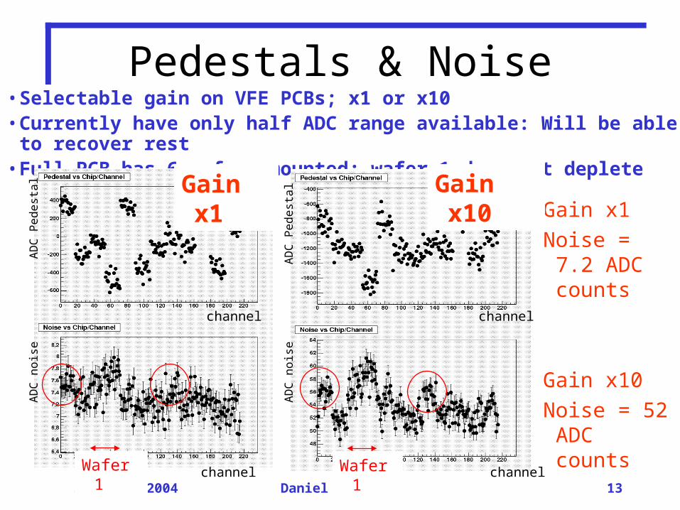
Pedestals & Noise• Selectable gain on VFE PCBs; x1 or x10• Currently have only half ADC range available: Will be able to recover rest• Full PCB has 6 wafers mounted; wafer 1 does not deplete
Gain x1
Noise = 7.2 ADC counts
Gain x10
Noise = 52 ADC counts
Gain x10Gain x1
Wafer 1 Wafer 1
channel
channel
channel
channel
AD
C n
ois
e
AD
C n
ois
e
AD
C P
ed
est
al
AD
C P
ed
est
al

30th June 2004 Daniel Bowerman 14
DAC Linearity calibration
• Slope ~2.5 ADC counts/DAC count
• High end saturation at ~ 12000 DAC counts
• Does not make good use of full DAC range
• 16-bits is 0-65535 counts; five times higher
• Can adjust and recover
• Low end saturation from readout board; understood
• Good consistency across channels
• Progressively pulse DAC and readout channels ADC value
• Typical channel (same as for DAC scan), gain x1
• Extra noise ~ 0.025 ADC counts/DAC
• Equivalent to extra noise of 1% of signal size
• Unknown if from calibration circuit or present in real signals
DAC pulse
DAC pulse
channel
AD
C r
espo
nse
AD
C n
oise
Slo
pe

30th June 2004 Daniel Bowerman 15
Crosstalk in DAC calibration• Look at non-enabled channel (next to previous one)
•Signal seen in neighbours
•Slope ~ 0.02 ~ 1% of signal slope
•Noise shows no increase
•Some examples where crosstalk is much greater
•Still trying to determine the origin
DAC pulse
DAC pulse
AD
C n
ois
eA
DC
res
pons
e

30th June 2004 Daniel Bowerman 16
Measuring Shaping Time• Output signal is shaped by CR-RC circuit, shaping time ~200ns• Set DAC and adjust sampling time to scan peak shape • Typical channel, gain x1• Fit xe–x shape to response• Shaping time = p3 = 31.36 units = 196 ns, good uniformity
Clock ticks (*6.25 ns) channel
Fitt
ed p
eak
time
30th June 2004 Daniel Bowerman 17
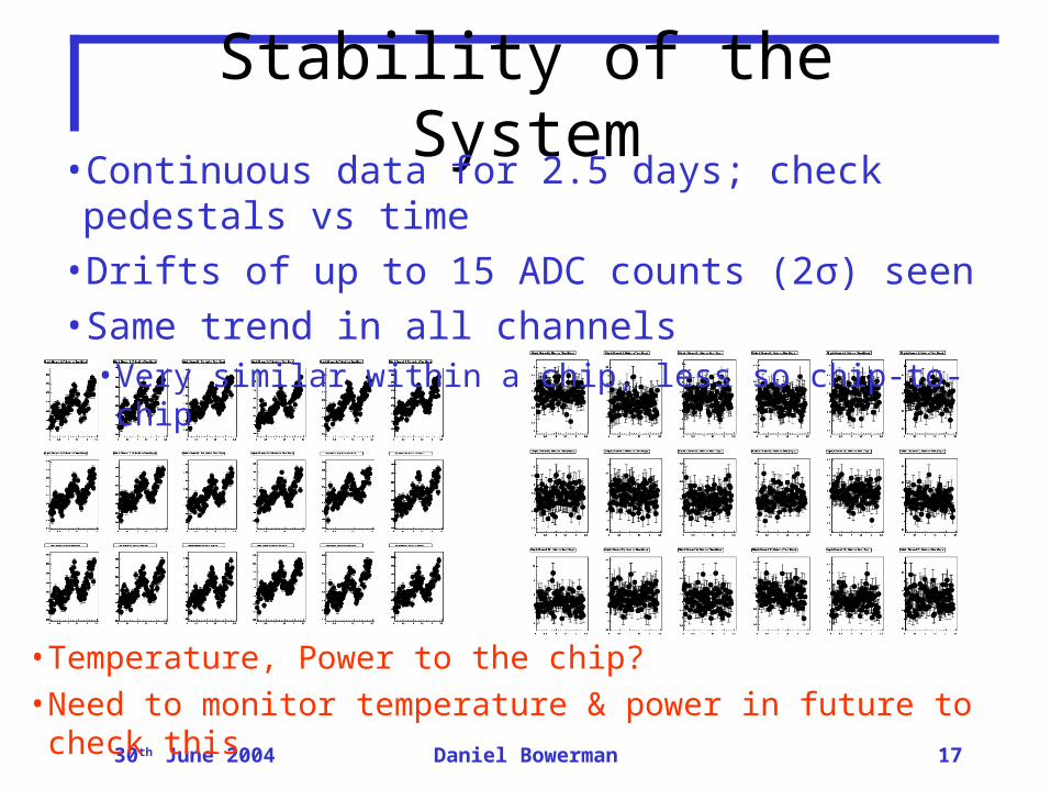
Stability of the System• Continuous data for 2.5 days; check pedestals vs time• Drifts of up to 15 ADC counts (2σ) seen• Same trend in all channels
• Very similar within a chip, less so chip-to-chip
• Temperature, Power to the chip?
• Need to monitor temperature & power in future to check this

30th June 2004 Daniel Bowerman 18
Full Chain - Cosmics
•Example of Cosmic Event
•Passes through scintillators
•Extrapolated through silicon
•Appears as clear signal above background
Scintillator
Scintillator
WaferX-Z
plane
Y-Zplane

30th June 2004 Daniel Bowerman 19
Cosmics Run• Full PCB used in Ecole Polytechnique teststand, but…
• Wafer 1 not depleted
• Bad ADC on CERC for wafer 4; half the wafer has very high noise
• Ran over weekend 18-21 June• Total ~ 57 hours, 130083 events
• Around 90% have unique track from scintillators
• Interpolate into plane of PCB; check for ADC value > 40
Wafer not depleting
Chip not working
cm cm
cmc
m
30th June 2004 Daniel Bowerman 20
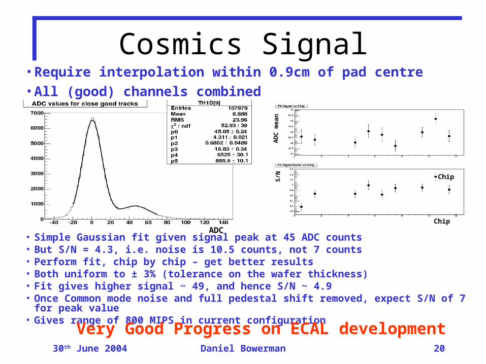
Cosmics Signal• Require interpolation within 0.9cm of pad centre• All (good) channels combined
• Simple Gaussian fit given signal peak at 45 ADC counts• But S/N = 4.3, i.e. noise is 10.5 counts, not 7 counts• Perform fit, chip by chip – get better results• Both uniform to ± 3% (tolerance on the wafer thickness)• Fit gives higher signal ~ 49, and hence S/N ~ 4.9• Once Common mode noise and full pedestal shift removed, expect S/N of 7 for peak value• Gives range of 800 MIPS in current configuration
ADC
AD
C m
ea
nS
/N
Chip
Chip
Very Good Progress on ECAL development

30th June 2004 Daniel Bowerman 21
Simulation 1 GeV + 50 GeV +
•Development of Hadronic Showers not fully understood in Simulation•Geant3 (histo)Geant3 (histo) and Geant4 (points) show basic differences in shower development •Aim to take the data and do detailed comparison of different models•Allow us to optimise proposed detector for LC•Work courtesy of D.Ward

30th June 2004 Daniel Bowerman 22
Comparing the Models
•Detailed comparison of the properties of different MC models underway•Combine G3 and G4 with different ‘physics’ implementations•ECAL shows EM discrepancies, but general consistent behaviour•Much greater variation for HCALWork by G.Mavromanolakis and N.Watson

30th June 2004 Daniel Bowerman 23
Comparing the Models
•HCAL rpc less sensitive to low energy neutrons than HCAL scint•Really shows that test beam studies are needed

30th June 2004 Daniel Bowerman 24
Particle Clustering Algorithm• Algorithm mixes tracking and
clustering aspects.
• Sum hits withn cell; apply threshold of ⅓ MIP.
• Form clusters in layer 1 of ECAL.
• Associate each hit in layer 2 with nearest hit in layer 1 within cone of angle α. If none, initiate new cluster.
• Track onwards layer by layer through ECAL and HCAL, looking back up to 2 layers to find nearest neighbour, if any.
Work by C.Ainsley

30th June 2004 Daniel Bowerman 25
Particle Clustering algorithmReconstructed clusters True particle clusters
Part of a 91 GeV Z event in the Calorimeter – Looks Good

30th June 2004 Daniel Bowerman 26
Full Z eventReconstructed clusters True particle clusters
30th June 2004 Daniel Bowerman 27
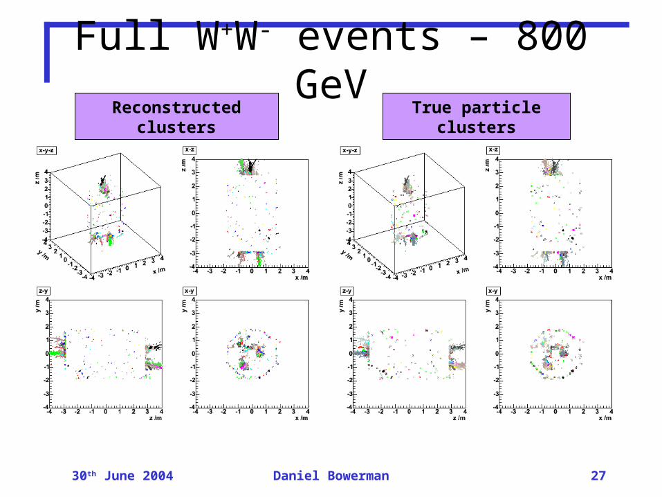
Full W+W- events – 800 GeVReconstructed clusters True particle clusters

30th June 2004 Daniel Bowerman 28
Initial Clustering Results Fraction of true cluster energy in each reconstructed cluster • Z to light quarks results – one Event
•15 highest energy reconstructed and true clusters plotted.
• Reconstructed and true clusters tend to have a 1:1 correspondence.
• Averaged over 100 Z events at 91 GeV:– 97.0 ± 0.3 % of event energy maps 1:1 from reconstructed onto true clusters.
Fraction of true cluster energy in each reconstructed cluster• WW at 800 GeV - one Event
•15 highest energy reconstructed and true clusters plotted.
• Reconstructed and true clusters tend to have a 1:1 correspondence.
• Averaged over 100 W+W events at 800 GeV: – 80.2 ± 1.0 % of event energy maps 1:1 from reconstructed onto true clusters.

30th June 2004 Daniel Bowerman 29
Readout effects in Simulation
6 GeV electrons
threshold cut = 0MeV per pad
pedestal = 32750 ADC counts
•Added a way for Readout effects to be included in the simulation
•Simple model adding noise with best to worst case scenarios
•For individual particles see acceptable loss in resolution
•Need to add realistic effects: Common Mode, Crosstalk…
•Interesting to see the effect on clusteringWork by C.Fry
30th June 2004 Daniel Bowerman 30
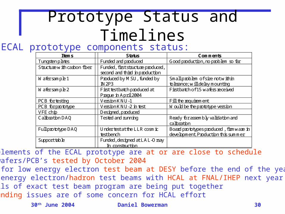
Prototype Status and TimelinesECAL prototype components status:
All elements of the ECAL prototype are at or are close to scheduleAll wafers/PCB’s tested by October 2004Plan for low energy electron test beam at DESY before the end of the yearHigh energy electron/hadron test beams with HCAL at FNAL/IHEP next yearDetails of exact test beam program are being put togetherUS funding issues are of some concern for HCAL effort
Items Status Comments Tungsten plates Funded and produced Good production, no problem so far Structure with carbon fiber Funded, first structure produced,
second and third in production
Wafer sample 1 Produced by MSU, funded by IN2P3
Small problem of size not within tolerance; will delay mounting
Wafer sample 2 First test batch produced at Prague in April 2004
First batch of 15 wafers received
PCB for testing Version KNU-1 Fill the requirement PCB for prototype Version KNU-2 in test Would be the prototype version VFE chip Designed, produced Calibration DAQ Tested and running Ready for assembly validation and
calibration Full prototype DAQ Under test at the LLR cosmic
test bench Board prototypes produced , firmware in development. Production this summer
Support table Funded, designed at LAL-Orsay In construction

30th June 2004 Daniel Bowerman 31
Conclusions•Great deal of progress in recent months•All prototype components in production and at or close to schedule
•ECAL detector chain undergoing full testing
•Captured Cosmics
•Good initial performance: S/N, Linearity, Crosstalk
•Beginning Production; ready for DESY e- test beam in December
•UK Simulation work shaping test beam requirements
•Key differences between G3/G4 and physics models
•Great progress on particle clustering/flow
UK groups at the heart of Calice
Well placed to take advantage of Test Beam data

30th June 2004 Daniel Bowerman 32
Back Up Slides

30th June 2004 Daniel Bowerman 33
Test Beam Requirements
1% precision suggests >104 events per particle type and energy.
Would like energies from 1-80 GeV (~10-15 energy points?).
Pions and protons desirable (Čerenkov needed). +Electrons (+
muons?) for calibration.
Need to understand beam
Both RPC and Scintillator HCAL needed.
Position scan – aim for 106 events/energy point?
Also some data at 30-45o incidence.
30th June 2004 Daniel Bowerman 34
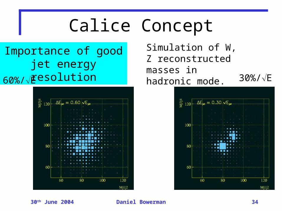
Calice ConceptSimulation of W, Z reconstructed masses in hadronic mode.
Importance of good jet energy resolution
60%/E 30%/E

30th June 2004 Daniel Bowerman 35
Basic issues with Simulation