3 XII December 2015 - IJRASET
11
3 XII December 2015
Transcript of 3 XII December 2015 - IJRASET

3 XII December 2015

www.ijraset.com Volume 3 Issue XII, December 2015 IC Value: 13.98 ISSN: 2321-9653
International Journal for Research in Applied Science & Engineering Technology (IJRASET)
©IJRASET 2015: All Rights are Reserved
296
Minimization of Voltage Sag/Swell by Simultaneous Controlling Of Active and Reactive Powers in
UPQC-S Dr. Chandrashekhar Reddy.S
Professor, Department of Electrical & Electronics Engineering, Christu Jyothi Institute of Technology & Science, Jangaon, Warangal-506167 -Telangana
Abstract-This paper aims at presenting the new concept of controlling active and reactive powers simultaneously (complex power) with the help of the series inverter of UPQC, introduced and termed as UPQC-S. The new proposed concept of the UPQC-S approach is mathematically formulated and analyzed for voltage sag and swell conditions in power systems. The developed comprehensive equations for UPQC-S can be effectively utilized to estimate the required series injection voltage and the shunt compensating current profiles (both magnitude of simultaneous voltage sag/swell and load reactive power sharing feature of series part and phase angle), and the overall VA loading both under voltage sag and swell conditions. . The simulation studies illustrate the effectiveness of the proposed concept of UPQC-S. Keywords – Active power, Reactive Power, UPQC, Sag and Swell.
I. INTRODUCTION
Power quality issues are becoming more and more significant in these days because of the increasing number of power electronic devices that behave as nonlinear loads. A wide diversity of solutions to power quality problems is available for both the distribution network operator and the end use. The power processing at source, load and for reactive and harmonic compensation by means of power electronic devices is becoming more prevalent due to the vast advantages offered by them. The shunt active power filter (APF) is usually connected across the loads to compensate for all current related problems such as the reactive power compensation, power factor improvement, current harmonic compensation and load unbalance compensation, whereas the series active power filter is connected in a series with a line through series transformer. It acts as controlled voltage source and can compensate all voltage related problems, such as voltage harmonics, voltage sag, voltage swell, flicker, etc. UPQC is a Custom Power Device and consists of combined series active power filter that compensates voltage harmonics, voltage unbalance, voltage flicker, voltage sag/swell and shunt active power filter that compensates current harmonics, current unbalance and reactive current. Unified Power Quality Conditioner is also known as universal power quality conditioning system, the universal active power line conditioner and universal active filter. UPQC system can be divided into two sections: The control unit and the power circuit. Control unit includes disturbance detection, reference signal generation, gate signal generation and voltage/current measurements. Power circuit consists of two Voltage source converters, standby and system protection system, harmonic filters and injection transformers.
II. MATHEMATICAL MODELLING
A UPQC is one of the most suitable devices to control the voltage sag/swell on the system. The rating of a UPQC is governed by the percentage of maximum amount of voltage sag/swell need to be compensated. However, the voltage variation (sag/swell) is a short duration power quality issue. Therefore, under normal operating condition, the series inverter of UPQC is not utilized up to its true capacity.
A. Fundamentals Of PAC Concept The concept of PAC of UPQC suggests that with proper control of the power angle between the source and load voltages, the load reactive power demand can be shared by both shunt and series inverters without affecting the overall UPQC rating. Similar to PAC of UPQC, the reactive power flow control utilizing shunt and series inverters is also done in a unified power flow controller (UPFC). A UPFC is utilized in a power transmission system whereas a UPQC is employed in a power distribution system to perform the shunt and series compensation simultaneously. The power transmission systems are generally operated in balanced
www.ijraset.com Volume 3 Issue XII, December 2015 IC Value: 13.98 ISSN: 2321-9653
International Journal for Research in Applied Science & Engineering Technology (IJRASET)
©IJRASET 2015: All Rights are Reserved
297
and distortion-free environment, contrary to power distribution systems that may contain dc component, distortion, and unbalance. The primary objective of a UPFC is to control the flow of power at fundamental frequency. Also, while performing this power flow control in UPFC the transmission network voltage may not be maintained at the rated value. However, in PAC of UPQC the load side voltage is strictly regulated at rated value while performing load reactive power sharing by shunt and series inverters. In this paper, the concept of PAC of UPQC is further expanded for voltage sag and swells conditions. This modified approach is utilized to compensate voltage sag/swell while sharing the load reactive power between two inverters. Since the series inverter of UPQC in this case delivers both active and reactive powers, it is given the name UPQCS (S for complex power). The key contributions of this paper are outlined as follows. The series inverter of UPQC-S is utilized for simultaneous voltage sag/swell compensation and load reactive power compensation in coordination with shunt inverter. In UPQC-S, the available VA loading is utilized to its maximum capacity during all the working conditions contrary to UPQC-VAmin where prime focus is to minimize the VA loading of UPQC during voltage sag condition. The concept of UPQC-S covers voltage sag as well as swell scenario. In this paper, a detailed mathematical formulation of PAC for UPQC-S is carried out. The feasibility and effectiveness of the proposed UPQC-S approach are validated by simulation results.
Fig.1 Concept of PAC of UPQC.
The phasor representation of the PAC approach under a rated steady-state condition is shown in Fig.1. According to this theory, a
vector with proper magnitude VSr and phase angle ϕSr when injected through series inverter gives a power angle δ boost
between the source VS and resultant load voltages maintaining the same voltage magnitudes. This power angle shift causes a
relative phase advancement between the supply voltage and resultant load current , denoted as angle β. In other words, with PAC approach, the series inverter supports the load reactive power demand and thus, reducing the reactive power demand shared by the sh For a rated steady-state condition
V V V V K 'S L LL
… (1)
Using Eq.1, phasor _VSr can be defined as Where V V
Sr Sr Sr
1 sin. 2 . 1 co s 1 80 tan1 co s
k
…. (2)
1s in QP
L
S r ….(3)
B. Voltage Sag/Swell Compensation Utilizing UPQC-P and UPQC-Q The voltage sag on a system can be compensated through active power control and reactive power control methods. Fig. 2 shows the phasor representations for voltage sag compensation using active power control as in UPQC-P [see Fig. 2(a)] and reactive power control as in UPQC-Q [see Fig. 2(b)]. Fig. 2(c) and (d) shows the compensation capability of UPQC-P and UPQC-Q to compensate swell on the system. For a voltage swell compensation using UPQC-Q [see Fig. 2(d)], the quadrature component injected by series inverter does not intersect with the rated voltage locus. Thus, the UPQC-Q approach is limited to compensate the sag on the system. However, the UPQC-P approach can effectively compensate both voltage sag and swell on the system. Furthermore, to compensate an equal percentage of sag, the UPQC-Q requires lager

www.ijraset.com Volume 3 Issue XII, December 2015 IC Value: 13.98 ISSN: 2321-9653
International Journal for Research in Applied Science & Engineering Technology (IJRASET)
©IJRASET 2015: All Rights are Reserved
298
magnitude of series injection voltage than the UPQC-P (VQSr > VP
Sr ).
Fig. 2 Voltage sag and swell compensation using UPQC-P and UPQC-Q: phasor representation.(a) Voltage Sag (UPQC-P). (b) Voltage Sag(UPQC-Q). (c) Voltage Swell (UPQC-P). (d) Voltage Swell (UPQC-Q).
Interestingly, UPQC-Q also gives a power angle shift between resultant load and source voltages, but this shift is a function of amount of sag on the system. Thus, the phase shift in UPQCQ cannot be controlled to vary the load reactive power support. Additionally, the phase shift in UPQC-Q is valid only during the voltage sag condition. Therefore, in this paper, PAC concept is integrated with active power control approach to achieve simultaneous voltage sag/swell compensation and the load reactive power support utilizing the series inverter of UPQC. This new approach in which the series inverter of UPQC performs dual functionality is named as UPQC-S.
C. PAC Approach under Voltage Sag Condition Consider that the UPQC system is already working under PAC approach, i.e., both the inverters are compensating the load reactive power and the injected series voltage gives a power angle δ between resultant load and the actual source voltages. If a sag/swell condition occurs on the system, both the inverters should keep supplying the load reactive power, as they were before the sag. Additionally, the series inverter should also compensate the voltage sag/swell by injecting the appropriate voltage component. In other words, irrespective of the variation in the supply voltage the series inverter should maintain same power angle δ between both the voltages. However, if the load on the system changes during the voltage sag condition, the PAC approach will give a different δ angle. The increase or decrease in new δ angle would depend on the increase or decrease in load reactive power, respectively.
Fig. 3 Phasor representation of the proposed UPQC-S approach under voltage sag condition.
D. PAC Approach Under Voltage Swell Condition

www.ijraset.com Volume 3 Issue XII, December 2015 IC Value: 13.98 ISSN: 2321-9653
International Journal for Research in Applied Science & Engineering Technology (IJRASET)
©IJRASET 2015: All Rights are Reserved
299
The phasor representation for PAC of UPQC-S during a voltage swell on the system is shown in Fig. 4. Let us represent a vector VSr3 responsible to compensate the swell on the system using active power control approach. For simultaneous compensation, the
series inverter should supply the component to support the load reactive power and to compensate the swell on the
system. The resultant series injected voltage would maintain the load voltage magnitude at a desired level while supporting the load reactive power.
Fig. 4 phasor representation of the proposed UPQC-S approach under voltage swell condition.
E. UPQC-S Controller A detailed controller for UPQC based on PAC approach is described. In this paper, the generation of reference signals for series inverter is discussed. Note that, as the series inverter maintains the load voltage at desired level, the reactive power demanded by the load remains unchanged (assuming load on the system is constant) irrespective of changes in the source voltage magnitude. Furthermore, the power angle δ is maintained at constant value under different operating conditions. The reactive power shared by the series and shunt inverters can be fixed at constant values by allowing the power angle δ to vary under voltage sag/swell condition.The control block diagram for series inverter operation is shown in Fig. 5. Based on the system rated specifications, the value of the desired load voltage is set as reference load voltage k. The instantaneous value of factors kf and nO is computed by measuring the peak value of the supply voltage in real time. A phase locked loop is used to synchronize and to generate instantaneous time variable reference signals v*sr.a. v*sr.b, v*sr.c. The reference signals thus generated give the necessary series injection voltages that will share the load reactive power and compensate for voltage sag/swell as formulated using the proposed approach. The error signal of actual and reference series voltage is utilized to perform the switching operation of series inverter of UPQC-S.
Fig. 5 Reference Voltage Signal generation for the series inverter of the Proposed UPQC-S approach

www.ijraset.com Volume 3 Issue XII, December 2015 IC Value: 13.98 ISSN: 2321-9653
International Journal for Research in Applied Science & Engineering Technology (IJRASET)
©IJRASET 2015: All Rights are Reserved
300
III. RESULTS AND ANALYSIS
The performance of the proposed concept of simultaneous load reactive power and voltage sag/swell compensation has been evaluated by simulation. To analyse the performance of UPQC-S, the source is assumed to be pure sinusoidal. Further more, for better visualization of results the load is considered as highly inductive. The supply voltage which is available at UPQC terminal is considered as three phase, 60 Hz, 600 V (line to line) with the maximum load power demand of 15 kW + j 15 kVAR (load power factor angle of 0.707 lagging). The simulation results for the proposed UPQC-S approach under voltage sag and swell conditions are given Before time t1 , the UPQC-S system is working under steady state condition, compensating the load reactive power using both the
inverters. A power angle δ of 21◦ is maintained between the resultant load and actual source voltages. The series inverter shares 1.96 kVAR per phase (or 5.8 kVAR out of 15 kVAR) demanded by the load. Thus, the reactive power support from the shunt inverter is reduced from 15 to 9.2 kVAR by utilizing the concept of PAC. In other words, the shunt inverter rating is reduced by 25% of the total load kilovolt ampere rating. At time t1 = 0.6 s, a sag of 20% is introduced on the system (sag last till time t = 0.7 s). Between the time period t = 0.7 s and t = 0.8 s, the system is again in the steady state. A swell of 20% is imposed on the system for a duration of t2 = 0.8–0.9 s.
Simulating time period is 0.95 secc
Fig. 6 Supply voltage
In the above Supply Voltage The sag occurs in the time period of 0.6ssec to 0.7sec and 07.sec to 0.8sec stead state occurs. 0.8sec to 0.9sec the swell occurs. here voltage decreases current increases.
Fig. 7 Load voltage In the above simulation of Load voltage is pure sinusoidal wave form occurs because any faults occurs in the Load side .The UPQC compensate the faults.

www.ijraset.com Volume 3 Issue XII, December 2015 IC Value: 13.98 ISSN: 2321-9653
International Journal for Research in Applied Science & Engineering Technology (IJRASET)
©IJRASET 2015: All Rights are Reserved
301
Fig. 8 Self supporting dc bus voltage
In the above dc bus voltage sag occurs 0.6sec to 0.7sec and swell occurs 0.8sec to 0.9sec.
Fig. 9 Supply current in the supply current In the supply current swell occurs 0.6sec to 0.7sec.here first swell occurs because voltage decreases and current increases.0.8sec to 0.9sec swell occurs.
Fig. 10 Shunt inverter injected current In shunt inverter injected current faults are Occurred.sag occurred in time period of 0.6sec to 0.7sec. Swell occurred 0.8sec to 0.9sec.
www.ijraset.com Volume 3 Issue XII, December 2015 IC Value: 13.98 ISSN: 2321-9653
International Journal for Research in Applied Science & Engineering Technology (IJRASET)
©IJRASET 2015: All Rights are Reserved
302
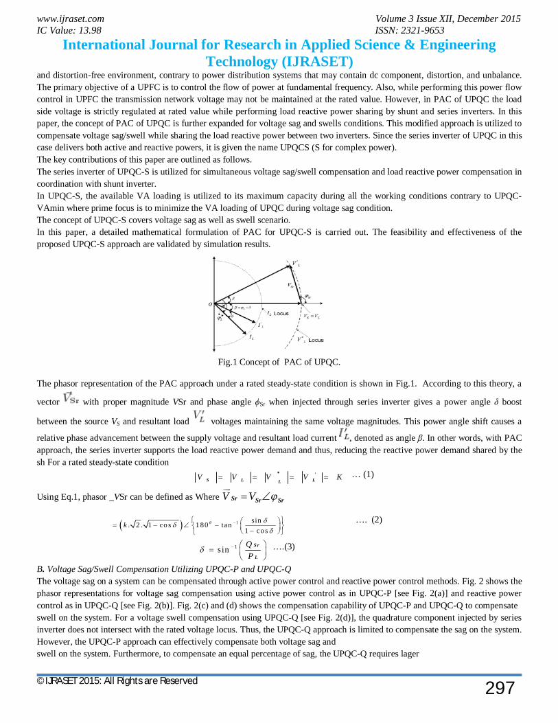
Fig. 11 Series inverter P and Q
In series inverter active and reactive powers are increases in 0.6sec to 0.7sec due to increase of the load current. Active and reactive powers are decreased in time period 0.8 sec to 0.9 sec.
Fig. 12 Shunt Inverter P and Q In the above shunt inverter and active and reactive powers are shown. In shunt inverter reactive power is decreased at that time active power is increased. With VDC controller Simulation results.
Fig. 13 Self supporting dc bus voltage In self supporting dc bus voltage using dc regulated transient response is decreased and system dynamic performance increased.

www.ijraset.com Volume 3 Issue XII, December 2015 IC Value: 13.98 ISSN: 2321-9653
International Journal for Research in Applied Science & Engineering Technology (IJRASET)
©IJRASET 2015: All Rights are Reserved
303
Fig.14 series inverter P and Q Using the dc regulator of series active and reactive powers are transient response is decreased. System starting period also decreased.
Fig.15 shunt inverter P and Q
In shunt inverter active and reactive power is shunt reactive power is increased series active power decreased .system dynamic performance increases.
IV. CONCLUSION
A new concept of controlling complex power (simultaneous active and reactive powers) through series inverter of UPQC is introduced and named as UPQC-S. The proposed concept of the UPQC-S approach is mathematically formulated and analyzed for voltage sag and swell conditions. The developed comprehensive equations for UPQC-S can be utilized to estimate the required series injection voltage and the shunt compensating current profiles (magnitude and phase angle), and the overall VA loading both under voltage sag and swell conditions. The simulation studies demonstrate the effectiveness of the proposed concept of simultaneous voltage sag/swell and load reactive power sharing feature of series part of UPQC-S
REFERENCES
[1] Vinod Khadkikar and Ambrish Chandra, “A Novel Concept of Simultaneous Voltage Sag/Swell and Load Reactive Power Compensations Utilizing Series Inverter of UPQC,” IEEE Trans. Power Electron., vol. 26, no. 9, pp. 2414–2425, Sep. 2011.
[2] Y. Chen, C. Lin, J. Chen, and P. Cheng, “An inrush mitigation technique of load transformers for the series voltage sag compensator,” IEEE Trans. Power Electron., vol. 25, no. 8, pp. 2211–2221, Aug. 2010.
[3] S. Subramanian and M. K. Mishra, “Interphase AC–AC topology for voltage sag supporter,” IEEE Trans. Power Electron., vol. 25, no. 2, pp. 514–518, Feb. 2010.
[4] H. Fujita and H. Akagi IEEE Trans. Power Electron., vol. 13, no. 2, pp. 315–322, Mar. 1998. [5] V. Khadkikar and A. Chandra, “A new control philosophy for a unified power quality conditioner (UPQC) to coordinate load-reactive power demand between
shunt and series inverters,” IEEE Trans. Power Del., vol. 23, no. 4, pp. 2522–2534, Oct. 2008. [6] M. Vilathgamuwa, Z. H. Zhang, and S. S. Choi, “Modeling, analysis and control of unified power quality conditioner,” in Proc. IEEE Harmon. Quality Power,
Oct. 14–18, 1998, pp. 1035–1040.

www.ijraset.com Volume 3 Issue XII, December 2015 IC Value: 13.98 ISSN: 2321-9653
International Journal for Research in Applied Science & Engineering Technology (IJRASET)
©IJRASET 2015: All Rights are Reserved
304
[7] M. Gon, H. Liu, H. Gu, and D. Xu, “Active voltage regulator based on novel synchronization method for unbalance and fluctuation compensation,” in Proc. IEEE Ind. Electron. Soc (IECON), Nov. 5–8,, 2002, pp. 1374–1379.
[8] M. S. Khoor and M. Machmoum, “Simplified analogical control of a unified power quality conditioner,” in Proc. IEEE Power Electron. Spec. Conf. (PESC), Jun., 2005, pp. 2565–2570.
[9] V. Khadkikar, A. Chandra, A. O. Barry, and T. D. Nguyen, “Analysis of power flow in UPQC during voltage sag and swell conditions for selection of device ratings,” in Proc. IEEE Electr. Computer Eng. (CCECE), May 2006, pp. 867–872.
[10] B. Han, B. Bae, H. Kim, and S. Baek, “Combined operation of unified power-quality conditioner with distributed generation,” IEEE Trans. Power Del., vol. 21, no. 1, pp. 330–338, Jan. 2006.
[11] H. R. Mohammadi, A. Y. Varjani, and H. Mokhtari, “Multiconverter unified power-quality conditioning system:MC-UPQC,” IEEE Trans. Power Del., vol. 24, no. 3, pp. 1679–1686, Jul. 2009.
[12] I. Axente, J. N. Ganesh, M. Basu, M. F. Conlon, and K. Gaughan, “A 12-kVA DSP-controlled laboratory prototype UPQC capable of mitigating unbalance in source voltage and load current,” IEEE Trans. Power Electron., vol. 25, no. 6, pp. 1471–1479, Jun. 2010.
[13] M. Basu, S. P. Das, and G. K. Dubey, “Investigation on the performance of UPQC-Q for voltage sag mitigation and power quality improvement at a critical load point,” IET Generat., Transmiss. Distrib., vol. 2, no. 3, pp. 414–423, May 2008.
[14] V. Khadkikar and A. Chandra, “A novel control approach for unified power quality conditioner Q without active power injection for voltage sag compensation,” in Proc. IEEE Int. Conf. Ind. Technol. (ICIT), Dec. 15–17, 2006, pp. 779–784.
[15] M. Yun, W. Lee, I. Suh, and D. Hyun, “A new control scheme of unified power quality compensator-Q with minimum power injection,” in Proc. IEEE Ind. Electron. Soc. (IECON), Nov. 2–6,, 2004, pp. 51–56.
[16] Y. Y. Kolhatkar and S. P. Das, “Experimental investigation of a singlephase UPQC with minimum VA loading,” IEEE Trans. Power Del., vol. 22, no. 1, pp. 373–380, Jan. 2007.