3-Way Butterfly Valve Series 1800 - Valtorc International Butterfly Valve Series 1800 3-Way...
12
Transcript of 3-Way Butterfly Valve Series 1800 - Valtorc International Butterfly Valve Series 1800 3-Way...
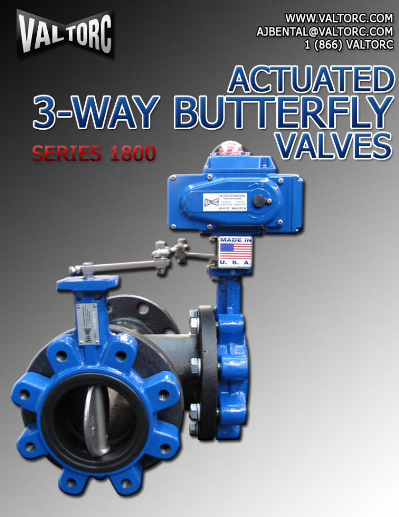
VALlctlRe l -WAV liUJflf~RFrLV VAL'6~~ 1 s~~~~s 1smm
.l
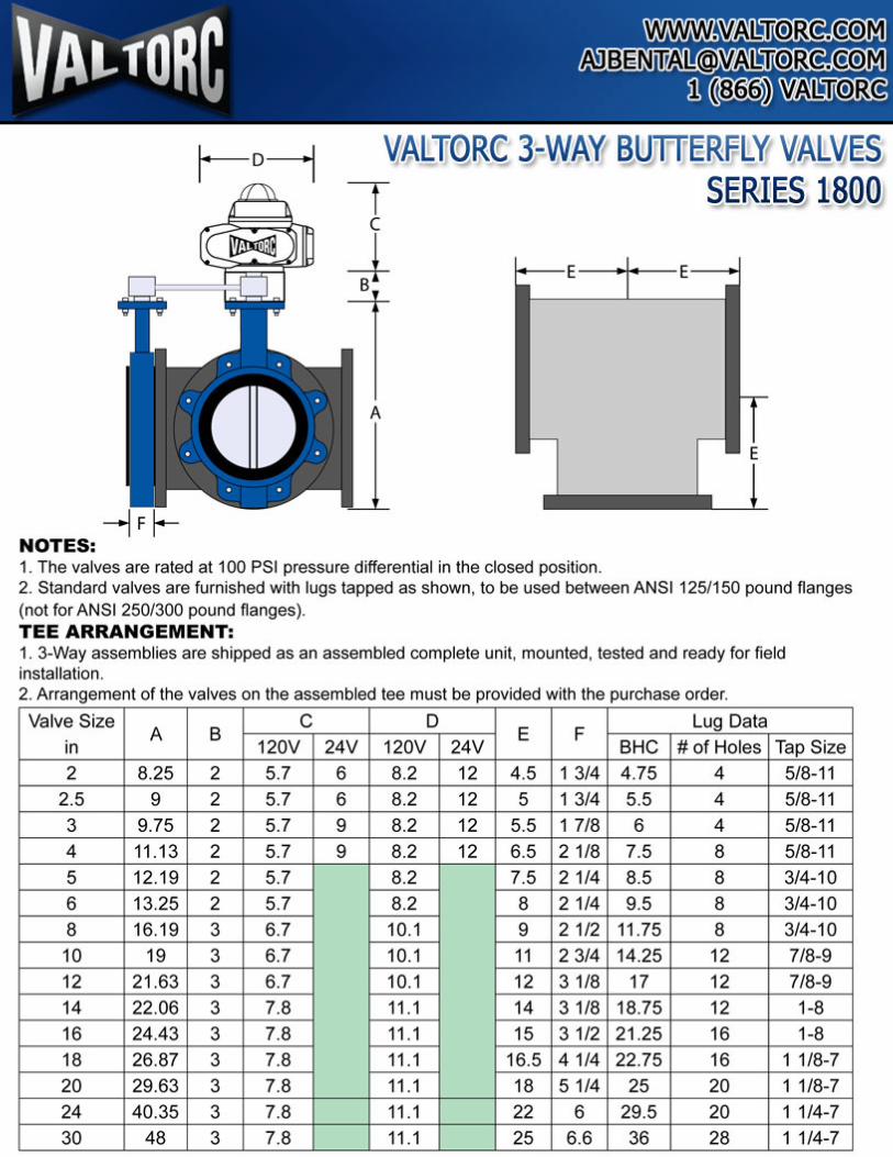
NOTES: 1. The valves are rated at 100 PSI pressure differential in the closed position. 2. Standard valves are furnished with lugs tapped as shown, to be used between ANSI 125/150 pound flanges (not for ANSI 250/300 pound flanges). TEE ARRANGEMENT: 1. 3-Way assemblies are shipped as an assembled complete unit, mounted, tested and ready for field installation. 2. Arrangement of the valves on the assembled tee must be provided with the purchase order.
Valve Size A B
c D E F
Lug Data
in 120V 24V 120V 24V BHC #of Holes Tap Size
2 8.25 2 5.7 6 8.2 12 4.5 1 3/4 4 .75 4 5/8-11
2.5 9 2 5.7 6 8.2 12 5 1 3/4 5.5 4 5/8-11
3 9.75 2 5.7 9 8.2 12 5.5 1 7/8 6 4 5/8-11
4 11.13 2 5.7 9 8.2 12 6.5 2 1/8 7.5 8 5/8-11
5 12.19 2 5.7 8.2 7.5 2 1/4 8 .5 8 3/4-10
6 13.25 2 5.7 8.2 8 2 1/4 9.5 8 3/4-10
8 16.19 3 6.7 10.1 9 2 1/2 11 .75 8 3/4-10
10 19 3 6.7 10.1 11 2 3/4 14.25 12 7/8-9
12 21.63 3 6.7 10.1 12 3 1/8 17 12 7/8-9
14 22.06 3 7.8 11.1 14 3 1/8 18.75 12 1-8
16 24.43 3 7.8 11.1 15 3 1/2 21.25 16 1-8
18 26.87 3 7.8 11.1 16.5 4 1/4 22.75 16 1 1/8-7
20 29.63 3 7.8 11.1 18 5 1/4 25 20 1 1/8-7
24 40.35 3 7.8 11.1 22 6 29.5 20 1 1/4-7
30 48 3 7.8 11.1 25 6.6 36 28 1 1/4-7
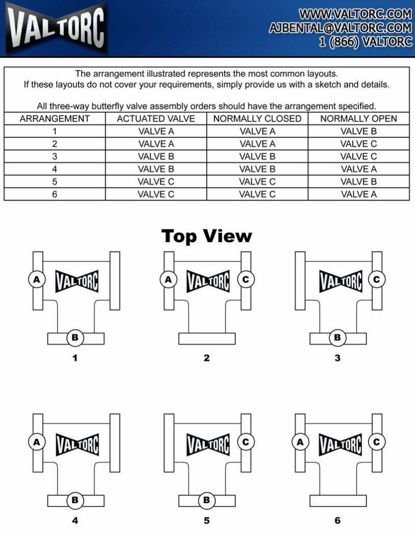
The arrangement illustrated represents the most common layouts. If these layouts do not cover your requirements, simply provide us with a sketch and details.
All three-way butterfly valve assembly orders should have the arrangement specified.
ARRANGEMENT ACTUATED VALVE NORMALLY CLOSED NORMALLY OPEN
1 VALVE A VALVE A VALVE B
2 VALVE A VALVE A VALVE C
3 VALVE B VALVE B VALVE C
4 VALVE B VALVE B VALVE A
5 VALVE C VALVE C VALVE B
6 VALVE C VALVE C VALVE A
Top View
1 2 3
4 5 6
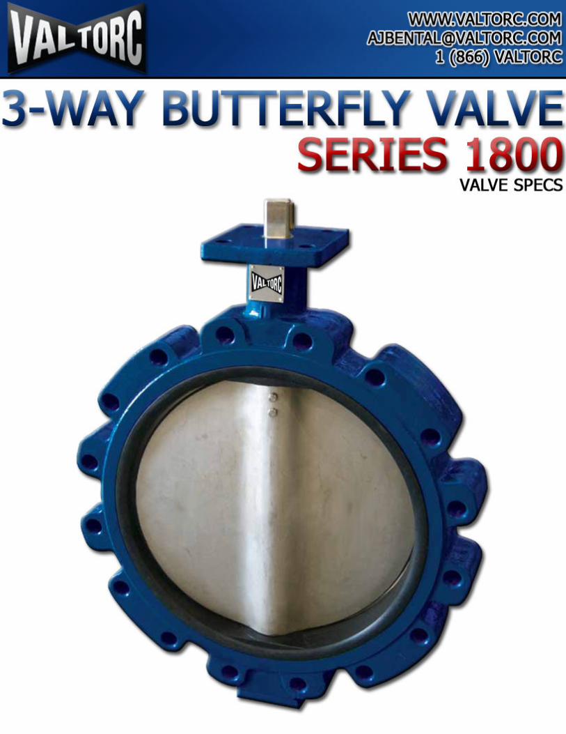
VALVE SPECS
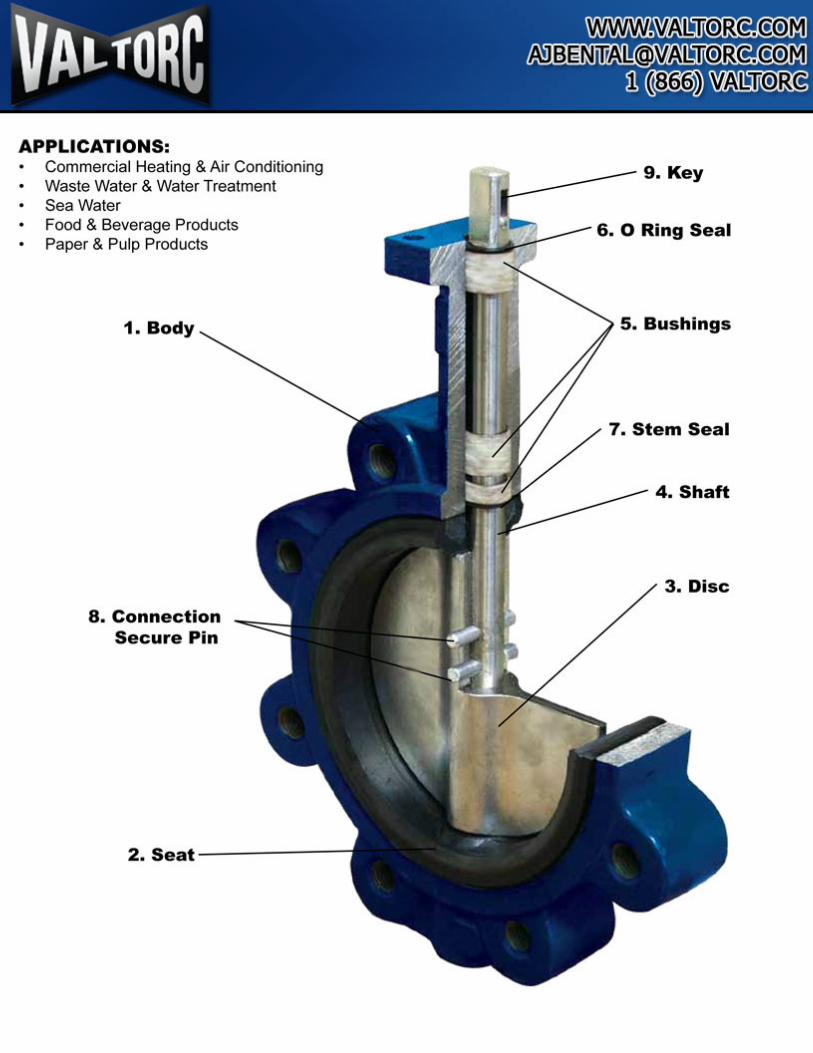
APPLICATIONS: Commercial Heating & Air Conditioning
• Waste Water & Water Treatment • Sea Water • Food & Beverage Products • Paper & Pulp Products
1. Body
8. Connection Secure Pin
2.Seat ----------~
5. Bushings
7. Stem Seal
4. Shaft
3. Disc
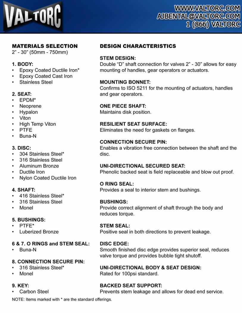
MATERIALS SELECTION 2" - 30" (50mm - 750mm)
1. BODY: • Epoxy Coated Ductile Iron* • Epoxy Coated Cast Iron • Stainless Steel
2. SEAT: • EPDM* • Neoprene • Hypalon • Viton • High Temp Viton • PTFE • Buna-N
3. DISC: • 304 Stainless Steel* • 316 Stainless Steel • Aluminum Bronze • Ductile Iron • Nylon Coated Ductile Iron
4. SHAFT: • 416 Stainless Steel* • 316 Stainless Steel • Monel
5. BUSHINGS: • PTFE* • Luberized Bronze
6 & 7. 0 RINGS and STEM SEAL: • Buna-N
8. CONNECTION SECURE PIN : • 316 Stainless Steel* • Monel
9. KEY: • Carbon Steel
DESIGN CHARACTERISTICS
STEM DESIGN: Double "D" shaft connection for valves 2" - 30" allows for easy mounting of handles, gear operators or actuators.
MOUNTING BONNET: Confirms to ISO 5211 for the mounting of actuators, handles and gear operators.
ONE PIECE SHAFT: Maintains disk position.
RESILIENT SEAT SURFACE: Eliminates the need for gaskets on flanges.
CONNECTION SECURE PIN: Enables a vibration free connection between the shaft and the disc.
UNI-DIRECTIONAL SECURED SEAT: Phenolic backed seat is field replaceable and blow out proof.
0 RING SEAL: Provides a seal to interior stem and bushings.
BUSHINGS: Provide correct alignment of shaft through the body and reduces torque.
STEM SEAL: Positive seal in both directions to prevent leakage.
DISC EDGE: Smooth fin ished disc edge provides superior seal, reduces valve torque and provides bubble tight shutoff.
UNI-DIRECTIONAL BODY & SEAT DESIGN: Rated for 100psi standard.
BACKED SEAT SUPPORT: Prevents stem leakage and allows for dead end service.
NOTE: Items marked with • are the standard offerings.
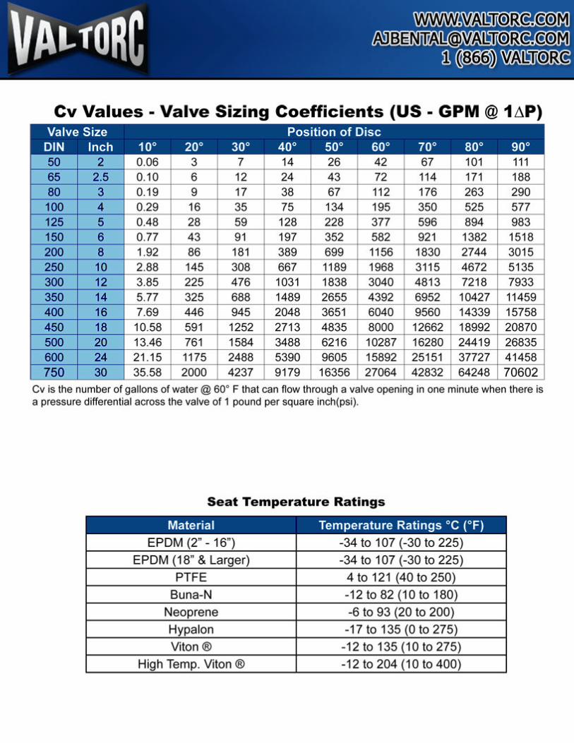
Cv Values • Valve Sizing Coefficients (US · GPM @ 1 ~P) Valve Size Position of Disc
DIN Inch 10° 20° Jo• 40° so· so· 7o• so· go• 50 2 0.06 3 7 14 26 42 67 101 111 65 2.5 0.10 6 12 24 43 72 11 4 171 188 80 3 0.19 9 17 38 67 112 176 263 290 100 4 0.29 16 35 75 134 195 350 525 577 125 5 0.48 28 59 128 228 377 596 894 983 150 6 0.77 43 91 197 352 582 921 1382 1518 200 8 1.92 86 181 389 699 1156 1830 2744 3015 250 10 2.88 145 308 667 1189 1968 3115 4672 5135 300 12 3.85 225 476 1031 1838 3040 4813 7218 7933 350 14 5.77 325 688 1489 2655 4392 6952 10427 11459 400 16 7.69 446 945 2048 3651 6040 9560 14339 15758 450 18 10.58 591 1252 2713 4835 8000 12662 18992 20870 500 20 13.46 761 1584 3488 6216 10287 16280 24419 26835 600 24 21.15 11 75 2488 5390 9605 15892 25151 37727 41458 750 30 35.58 2000 4237 9179 16356 27064 42832 64248 70602
Cv is the number of gallons of water@ 60• F that can flow through a valve opening in one minute when there is a pressure differential across the valve of 1 pound per square inch(psi).
Seat Temperature Ratings
Material Temperature Ratings •c (•F)
EPDM (2" - 16") -34 to 1 07 ( -30 to 225)
EPDM (18" & Larger) -34 to 107 (-30 to 225)
PTFE 4 to 121 (40 to 250) Buna-N -1 2 to 82 ( 1 0 to 180)
Neoprene -6 to 93 (20 to 200)
Hypalon -17 to 135 (0 to 275)
Viton ® -1 2 to 135 (10 to 275)
High Temp. Viton ® -12 to 204 (10 to 400)

VALVE DIMENSIONS 2"- 30"
For 30" Valve
1 1/4 4 5/8-11 4 4 Woodruff #3
32 12.G 10 9S 17& 4G 139.7 4 5/8-11 4 1 9.0·~ 90 70 4 10 Woodruff #3 1 114 1/2 0.39 3.66 6.89 1.81 5.5 314 3.54 2.76 318
75 32 12.6 10 99 181 46 152.4 4 5/8-11 4
19.05 90 70 4
10 Woodruff#3 1 1/4 112 0.39 3.9 7.13 1.81 6 314 3.54 2.76 318
100 32 15.77 12 116 200 52 190.5 8 5/8-11 4
19.05 90 70 4
10 Woodruff#3 1 1/4 5/8 0.47 4.57 7.87 2.05 7.5 314 3.54 2.76 318
125 32 18.92 14 130 213 56 2 15.9 8 3/4-10 4
22.23 90 70 4
10 Woodruff 119 1 114 3/4 0.55 5.12 8.39 2.20 8.5 718 3.54 2.76 318
1&0 32 18.92 14 144 226 56 241.3 8 3/4-10 4
22.23 90 70 4
10 Woodruff #9
1 1/4 3/4 0.55 5.67 8.90 2.20 9.5 718 3.54 2.76 318
200 45 22.1 17 177 260 60 298.5 8 3/4-10 4 22.23 125 102 4
12 Woodruff 119
1 3/4 718 0.67 6.97 10.24 2.36 11.75 7/8 4.92 4.02 7116
250 45 28.45 22 202 292 68 362 12 7/8-9 4 25.4 125 102 4
12 Woodruff #15
1 3/4 1 1/8 0.87 7.95 11.50 2.68 14.25 1 4.92 4.02 7116
300 45 31 .6 24 241 337 78 431.8 12 7/8-9 4 25.4 125 102
4 12
Woodruff #15 1 3/4 1 114 0.95 9.49 13.27 3.07 18.75 1 4.92 4.02 7116
350 45 31.6 24 280 368 78 476.3 12 1·8 4 28.58 125 102
4 12
Woodruff #15 1 3/4 1 114 0.95 11.02 14.49 3.07 18.75 1 1/8 4.92 4.02 7116
400 51 33.2 27 315 401 86 539.8 16 1-8 4 28.58 210 165 4 23 5/16Sqx1
2 1 5/16 1.06 12.4 15.79 3.39 21 .25 1 1/8 8.27 6.5 718 314
450 51 38 27 333 422 105 577.9 16 11 /8-7 4
31 .75 210 165 4 23 318 Sq X
2 11/2 1.06 13.11 16.6 1 4.13 22.75 1 1/4 8.27 6.5 718 11/2
500 64 41 32 365 479 130 635 20 1 1/8-7 4
31 .75 210 165 4
23 318 Sq X
2 1/2 1 5/8 1.26 14.37 18.86 5.12 25 1 114 8.27 6.5 718 1 3/4
500 70 50.6 36 463 562 152 749.3 20 1 114-7 4 34.93 210 165 4 23 112 Sq X
2 3/4 2 1.42 18.23 22.13 5.98 29.5 1318 8.27 6.5 718 2114
750 70 63.3 555 648 167 914 28 1 114-7 4 1 114-7 300 254
8 18 5/8 Sq X
2 3/4 21/2 21 .85 25.51 6.57 36 11.8 1 10 112 2 5/8
H 1* and 011* refer to lug style body types, H2* and 012* refer to wafer style bodies. Dimension F is the face to face of the valve body. This does not account for the valve seat. Approximately 1/8" additional spacing is required for proper seating with the pipe flanges. The installation does not require gaskets, as the valve seat creates the seal against the mounting flange.
Lug
Wafer
4 8.84
3 6.63
DIN
4 8.84
3 6.63
5 11 .05
4 8.84
8 17.68
5 11 .05
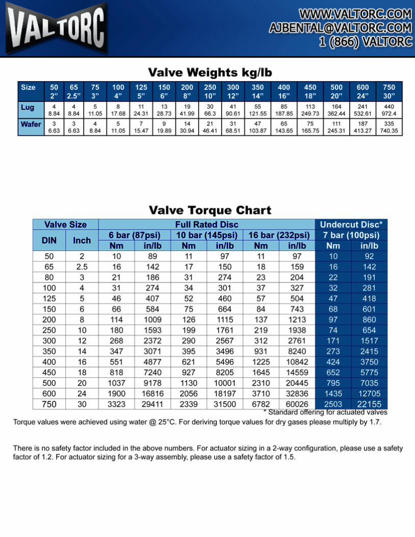
Valve Weights kg/lb
11 24.31
7 15.47
13 28.73
9 19.89
19 41.99
14 30.94
30 66.3
21 46.41
41 90.61
31 68.51
55 121.55
47 103.87
Valve Torque Chart
85 187.85
65 143.65
113 164 249.73 362.44
75 111 165.75 245.31
241 532.61
187 413.27
440 972.4
335 740.35
Torque values were achieved using water@ 2s•c. For deriving torque values for dry gases please multiply by 1. 7.
There is no safety factor included in the above numbers. For actuator sizing in a 2-way configuration, please use a safety factor of 1.2. For actuator sizing for a 3-way assembly, please use a safety factor of 1.5.
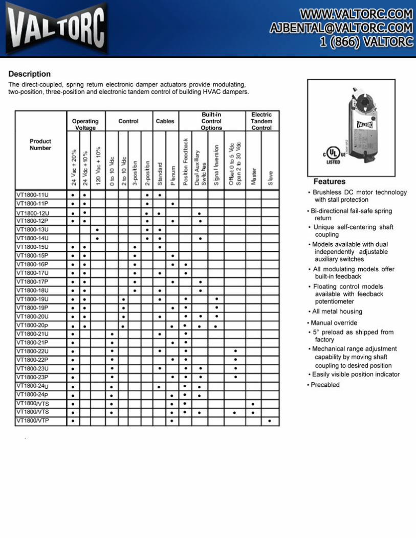
Description The direct-coupled, spring return electronic damper actuators provide modulating, two-position, three-position and electronic tandem control of building HVAC dampers.
Built--in Operating Control Cables Control Volta o 0 tions
Product "' u
~~ Number -$ 11 ~
.... .... !:! l 1:' ~ e ..,g
:<l !2 j j m
1 + ~ ~ "' ll g + + u .D .D 11 ~ X 00
~ ~ -J !2 !2 - - 0 E ~ ~2 - ~"' .. • ~ i!' .. a, .~ m
~ ~ ~ ll ll a ! • ~ ... iii J! J11 0 " ~ -"' 0~ "' 0 "' "' "' ... ... Oo> "'
VT18Q0.11U • • • • VT18Q0.11P • • • • VT180Q-12U • • • • • VT18Q0.12P • • • • • VT18Q0.13U • • • VT18Q0.14U • • • • VT18Q0.15U • • • • VT 18Q0.15P • • • • VT 18Q0.16P • • • • • VT18Q0.17U • • • • • VT18Q0.17P • • • • • VT18Q0.18U • • • • • VT18Q0.19U • • • • • • VT18Q0.19P • • • • • • VT18Q0.20U • • • • • • • VT18Q0.20p • • • • • • • VT18Q0.21U • • • • VT18Q0.21P • • • • VT18Q0.22U • • • • • VT18Q0.22P • • • • • VT18Q0.23U • • • • • • VT18Q0.23P • • • • • • VT18Q0.24u • • • • • VT18Q0.24p • • • • • VT1800NTS • • • • VT1800NTS • • • • • • VT1800NTP • •
Electric Tandem Control
-.!!l !I • ~ -"
"'
• •
•
Features • Brushless DC motor technology
with stall protection
• Bi-directional fail-safe spring return
• Unique self-centering shaft coupling
• Models available with dual independently adjustable auxiliary switches
• All modulat.ing models offer built-in feedback
• Floating control models available wilh feedback potentiometer
• All metal housing
• Manual override
• s• preload as shipped from factory
• Mechanical range adjustment capability by moving shaft coupling to desired position
• Easily visible position indicator
• Precabled
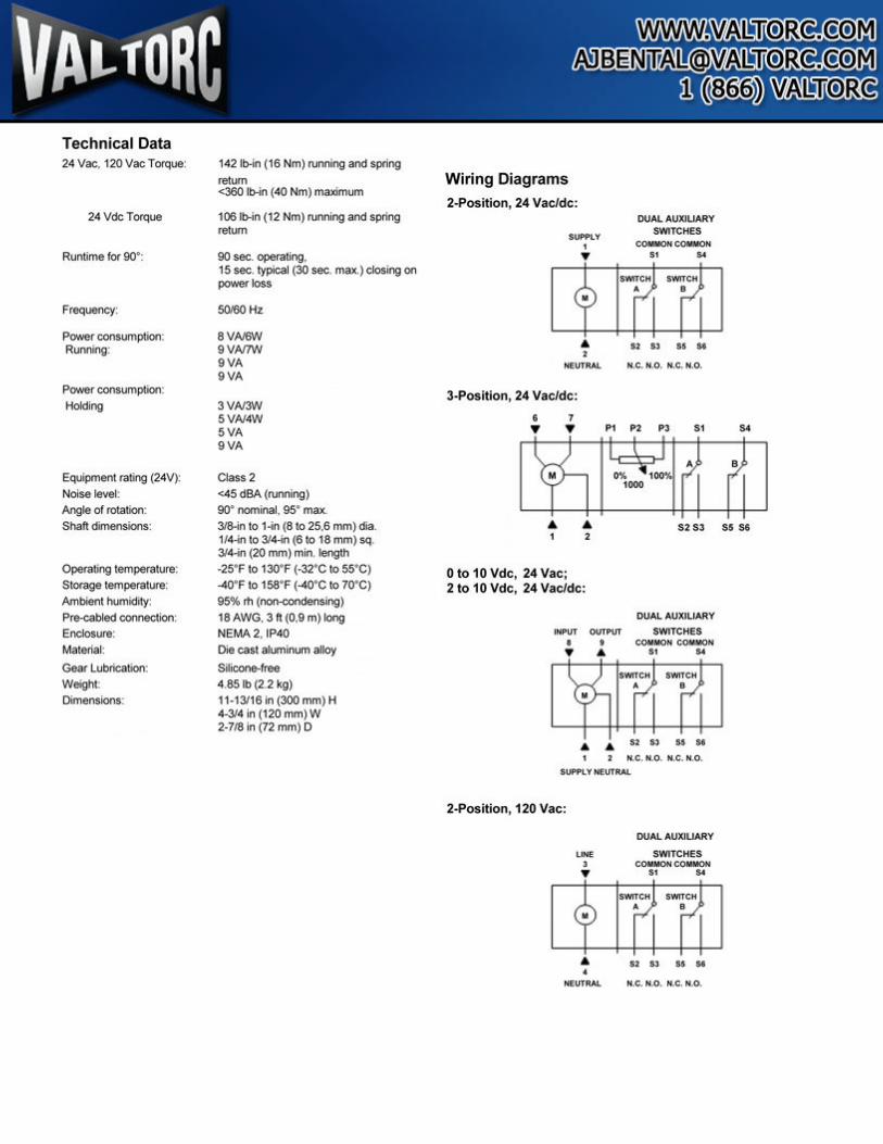
Technical Data 24 Vac. 120 Vac TOf<!ue:
24 Vdc Torque
Eq<~ipment rating (24V): Noise level: Angle of rotation: Shaft dimeflsioos:
Operating ternoel'ature: StO<age temperatura: Ambieflt humi<llly: Pre-cabled connection: Enclosure: Materiat
Gear l.tJbricatlon: WeOglll Dimensions:
14211>-in (18 Nm) IIJIIIWig and spring
retum <360 ll>in (40 Nm) mu>mum
I 08 lboln ( 12 Nm) n.ming and spring retum
90MC.~ 15 sec. typal (30 MC max.) c:loolr>g on _ .... 50160H2
8VMNI 9VA/1W 9VA 9VA
3VWSN 5Wv4W 5VA 9VA
018112 <45 dBA (running) 90• nominal. 95• max. 318-in to t -in (8 to 25,6 mm) dia. 114-ln to 314-in (6 to 18 mm) sq, 314-in (20 mm) min, length ·25' F to 130'F (->12' 0 to 55' 0) -40' F to 158' F (-40' 0 to 70'0) 95% m (non-condeflsing) t8 AWG, 3ft (0,9 m) long NEMA2, 1P40 Ole call Dlumin<Jm Dlloy
Stltcone-lree 4.851b (2 2 kg) t1· 131181n (300 mm) H 4-3/4 in (120 mm)W 2·718 in (72 mm) 0
Wiring Diagrams 2-Position, 24 Vaeldc:
• ""
DUAL AIJXIUARY SWITCHES --•• ..
lf1Tt61 • ' H£UfRAL
3.Position, 24 Vaeldc:
• 7
" .. .. .. fllC. k.O. N.C. N.O.
y y P1 P2 P) $1 $.t
lbi~M B I A A S2S3 S5Sf
2
0 to 10 Vdc, 24 Vac; 2 to 10 Vdc, 24 Vac/dc:
DUAL AUXILIARY
INPUT OVTPUT SWITCHES I t COMMQN~N • • $1 ...
a& S2PMN 2 N.C. N.O. N.C. M.O.
~y MlUJ11tAL
2.Position, 120 Vac:
DUAL AUXIJARY
UNE SWITCHES
' --If IMM I
A SlSl SSM
• NEUTRAL N.C. H.O. N.C. N 0 .
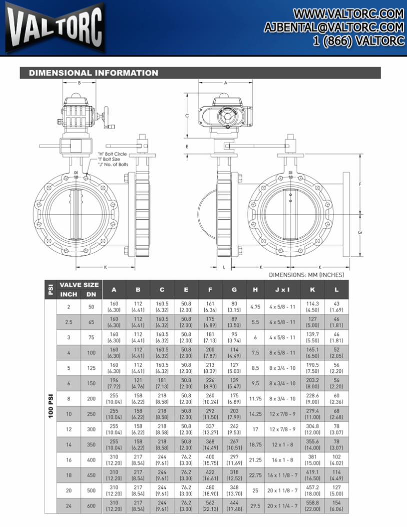
DIMENSIONAL INFORMATION 1---A---j
j I
DIMENSIONS: MM (I NCHES)
2 50 160 112 160.5 50.8 161 80 0 5 4x 5/8 -11 114.3 43
(6.301 (4.41) 16.32) 12.00) 16.341 (3.151 14.501 11 .691
2.5 65 160 112 160.5 50.8 175 89
5.5 4x5/8 - 11 127 46
(6.301 (4.41) 16.32) 12.001 16.891 (3.501 15.001 11.811
3 75 160 112 160.5 50.8 181 95 6 4x5/8- 11 139.7 46
(6.301 (4.41) (6.32) (2.00) 17.131 (3.741 15.501 11.811
4 100 160 112 160.5 50.8 200 114 7.5 8x5/8-11 165.1 52
(6.301 (4.41) 16.32) (2.00) 17.871 (4.491 16.501 12.051
5 125 160 112 160.5 50.8 213 127
8.5 8 x 3/4- 10 190.5 56
(6.301 (4.41) 16.32) 12.00) 18.391 15.001 17.501 12.201
6 ISO 9.5 8x3/4 - 10
;;; 8 200 255 11.75 8x3/4-10 ... 110.041
0 255 158 218 279.4 0 10 250 14.25 12x7/8-9 ... 110.041 16.221 18.58) 111.00)
12 300 255 158 218 17 12 x 7/8 - 9 304.8 78 110.041 16.221 18.58) 112.00) (3.071
" 350 255 18.75 12 X 1 -8 355.6 78
(10.041 114.00) 13.071
16 400 21.25 16 X 1 - 8
18 450 22.75 16x11/8 - 7
20 500 25 20 X 1 1/8- 7
24 600 29.5 20 X 1 1/4 - 7


![F6100HDU, 2-Way Butterfly Valve...4” [101.6] F6100HDU, 2-Way Butterfly Valve Resilient Seat, 304 Stainless Steel Disc 800-543-9038 USA 866-805-7089 CANADA 203-791-8396 LATIN AMERICA](https://static.fdocuments.net/doc/165x107/60c28bb7cacf0e0d38262e59/f6100hdu-2-way-butterfly-valve-4a-1016-f6100hdu-2-way-butterfly-valve.jpg)

![Hydrodynamic calculation Butterfly valve (lenticular disc) [EN] calculation Butterfly valve... · Hydrodynamic calculation Butterfly valve (lenticular disc)!=0,262’ (=1,15’ Fig.1](https://static.fdocuments.net/doc/165x107/5e4d4893a5620b2b3175568a/hydrodynamic-calculation-butterfly-valve-lenticular-disc-en-calculation-butterfly.jpg)