3. To speak of the current through a capacitor is ... fileFor a parallel-plate capacitor ... become...
12
11b Spring 2010 Lab 2: Capacitance and RC circuits I. Before you come to lab... A. Read the following sections from Giancoli: 1. Chapter 24, sections 1-5 2. Chapter 26, section 5-6 B. Read through this entire handout. C. Complete the pre-lab assignment at the end of the handout. II. Background A. Capacitors 1. Capacitors are circuit elements that store charge, consisting of two separated conductors (usually taken to be adjacent parallel plates). They are represented by the following symbol: 2. The voltage across a capacitor is equal to the charge stored on it divided by its capacitance, ΔV = Q/C. Capacitance is measured in farads (F); 1 farad = 1 coulomb per volt. For a parallel-plate capacitor (the most common kind), the capacitance is given by C = κε 0 A/d, where κ is the dielectric constant, ε 0 is the permittivity of vacuum, A is the area of each plate, and d is the separation distance. 3. To speak of the current "through" a capacitor is technically incorrect, as a capacitor consists of two non-touching conducting plates, and charge cannot flow from one to the other across the gap. However, everybody does it. What actually happens is that current deposits charge on one plate of the capacitor, and an equal current removes charge from the other plate at the same rate, so that the two plates always have equal and opposite charges. So it is actually quite convenient to think of it as being a single continuous current. Note that the current through a capacitor is the rate of change of the charge on the capacitor: I = dQ/dt. (There may be a minus sign, depending on whether the current is depositing charge on the + plate or the - plate.) 4. Capacitors in parallel add: Ceq = C1 + C2 + ... 5. Capacitors in series add inversely: 1/Ceq = 1/C1 + 1/C2 + ... 6. Capacitors store energy, which means it takes energy to charge a capacitor. However, unlike with resistors, you can get the energy back and use it to do useful work (for instance, like melting a piano wire into a zillion glowing pieces). The energy stored in a capacitor is given by U = ½ CΔV 2 = ½ Q 2 /C = ½ QΔV (all equivalent). When a capacitor is charging, energy is being put into it; when discharging, energy is being taken out of it and can be used elsewhere. So the electrical power consumed by a capacitor can be positive or negative. 7. Most capacitors are filled with a dielectric material, which increases is capacitance by reducing the electric field between the capacitor's plates. However, every dielectric material has a limit, called the dielectric strength, which is the maximum electric field (magnitude) that it can support before it breaks down. If the dielectric strength is exceeded, the dielectric will temporarily become conducting. If this happens, typically a spark jumps across the dielectric and reduces the potential difference across the capacitor's plates to nearly zero. This is the physical basis behind the phenomenon of static electric shocks and, on a more impressive scale, lightning—the dielectric breakdown of air.
Transcript of 3. To speak of the current through a capacitor is ... fileFor a parallel-plate capacitor ... become...

11b Spring 2010
Lab 2: Capacitance and RC circuits
I. Before you come to lab... A. Read the following sections from Giancoli:
1. Chapter 24, sections 1-5 2. Chapter 26, section 5-6
B. Read through this entire handout. C. Complete the pre-lab assignment at the end of the handout.
II. Background A. Capacitors
1. Capacitors are circuit elements that store charge, consisting of two separated conductors (usually taken to be adjacent parallel plates). They are represented by the following symbol:
2. The voltage across a capacitor is equal to the charge stored on it divided by its capacitance, ΔV = Q/C. Capacitance is measured in farads (F); 1 farad = 1 coulomb per volt. For a parallel-plate capacitor (the most common kind), the capacitance is given by C = κε0A/d, where κ is the dielectric constant, ε0 is the permittivity of vacuum, A is the area of each plate, and d is the separation distance.
3. To speak of the current "through" a capacitor is technically incorrect, as a capacitor consists of two non-touching conducting plates, and charge cannot flow from one to the other across the gap. However, everybody does it. What actually happens is that current deposits charge on one plate of the capacitor, and an equal current removes charge from the other plate at the same rate, so that the two plates always have equal and opposite charges. So it is actually quite convenient to think of it as being a single continuous current. Note that the current through a capacitor is the rate of change of the charge on the capacitor: I = dQ/dt. (There may be a minus sign, depending on whether the current is depositing charge on the + plate or the - plate.)
4. Capacitors in parallel add: Ceq = C1 + C2 + ... 5. Capacitors in series add inversely: 1/Ceq = 1/C1 + 1/C2 + ... 6. Capacitors store energy, which means it takes energy to charge a
capacitor. However, unlike with resistors, you can get the energy back and use it to do useful work (for instance, like melting a piano wire into a zillion glowing pieces). The energy stored in a capacitor is given by U = ½ CΔV2 = ½ Q2/C = ½ QΔV (all equivalent). When a capacitor is charging, energy is being put into it; when discharging, energy is being taken out of it and can be used elsewhere. So the electrical power consumed by a capacitor can be positive or negative.
7. Most capacitors are filled with a dielectric material, which increases is capacitance by reducing the electric field between the capacitor's plates. However, every dielectric material has a limit, called the dielectric strength, which is the maximum electric field (magnitude) that it can support before it breaks down. If the dielectric strength is exceeded, the dielectric will temporarily become conducting. If this happens, typically a spark jumps across the dielectric and reduces the potential difference across the capacitor's plates to nearly zero. This is the physical basis behind the phenomenon of static electric shocks and, on a more impressive scale, lightning—the dielectric breakdown of air.

B. Ground 1. As you already know, the potential can be arbitrarily defined to be
equal to zero at any one place. In an electrical circuit, the place where V is defined to be zero is called ground, and is represented in a circuit diagram by this symbol:
2. The reason that this place is called ground is that in many electric devices, the circuit ground is actually electrically connected to the Earth. The Earth is a fairly good conductor, and is a huge reservoir of charge, so you can flow a lot of current into or out of it without significantly affecting its potential. So the Earth makes an ideal ground. Just about every building with an electrical system has a set of wires that are connected to literal ground (a metal rod stuck into the Earth) to be used as circuit ground for anything plugged into that building.
3. In a circuit containing an explicit ground, we can talk about the "voltage" of a single point (remember, voltage is usually a potential difference between two points), meaning the voltage of that point relative to ground. In this usage, "voltage" is interchangeable with "potential" since ground is defined to have a potential of zero.
4. With a ground, you can have a circuit which doesn't even appear to be a complete circuit, because anything connected to ground is at the same potential and thus might as well be connected by a wire. For example, suppose you have a capacitor C. You ground both plates so that there is no voltage across C (and hence no charge). Then you touch one end of the capacitor to a high-voltage power supply at V = +1 kV. Even though you don't appear to have made a complete circuit, you actually have made the following circuit:
One end of the capacitor is still grounded because it was grounded before and it's been kept electrically isolated since then. The other end is now at +1000 V (relative to ground). In the circuit diagram, the two places labeled with the ground symbol are at the same potential, so this in turn is actually equivalent to:
In other words, you have charged up your capacitor to a voltage of 1 kV across its plates.
5. The existence of a huge conducting ground also means that we can define the concept of capacitance for a single isolated conductor: it is simply equal to the capacitance of the system consisting of the conductor plus the Earth (which is far away and at V=0). a. For example, consider a metal sphere of radius R. You can take
a charge Q out of the Earth (ostensibly leaving the Earth with -Q, but that doesn't affect the potential of the Earth because it is so vast) and put it on the sphere to give it charge +Q.
b. The charge will distribute itself evenly over the sphere's surface, creating an electric field E = Q/4πε0R2 pointing radially outward from the sphere.
c. The potential of the sphere relative to V=0 at infinity can be found by integration to be Q/4πε0R (just like the potential a distance R from a point charge Q).

d. If the sphere is "isolated" (far away) from the Earth, you now have a capacitor with "plates" of +Q and -Q charge and a potential difference ∆V = kQ/R. Using the definition of capacitance, C = Q/∆V = R/k = 4πε0R (Where k=8.99 x 10^9 Nm^2/C^2). That's what "the capacitance of a sphere" means; it's the capacitance relative to ground (the Earth).
e. Your own body is a reasonably good conductor. What do you think is the capacitance of your body?
C. RC circuits 1. Circuits containing a resistor and capacitor are called RC circuits.
They were discussed at great length in lecture and in section 26-5 of the text. We will not go over all the details, but here are the most important results.
2. RC circuits have a time dependence—that is, they are not static circuits. The main behavior is that they asymptotically approach a steady-state limit in which all voltages remain constant and all currents go to zero. (Remember, a non-zero capacitor current means that the charge—and therefore the voltage—on the capacitor is changing.)
3. Any voltage in an RC circuit relaxes towards its final steady-state value exponentially with time; that is, the difference between ∆V(t) and its final value decreases as exp(-t/τ), where τ (the greek letter tau) is called the time constant. In a circuit with capacitance C and resistance R, the numerical value of τ is equal to R times C. If R is in ohms and C in farads, then the product RC has units of seconds. (1 Ω = 1 V/A; 1 F = 1 C/V; so 1 Ω·F = 1 C/A = 1 s.)
4. The meaning of τ is that it is the time required for the exponential factor to become 0.37, or 37%. (Plugging in t=τ gives exp(-1), which is just 1/e, or about 0.37.) So for a voltage which is decaying to zero, τ is the time it takes for it to reach 37% of its initial value. For a voltage which is going from zero to some non-zero final value, τ is the time it takes to reach 63% of that final value (since the difference between ∆V and the final value decays to 37%).
5. You can usually determine all of the "initial" (right after the circuit is completed) voltages by applying Kirchhoff's loop rule and remembering that the charge on a capacitor cannot change instantaneously. Thus the voltage across a capacitor also cannot change instantaneously; right after any switch is thrown, the capacitor must have the same voltage it had right before.
6. The fact that all currents go to zero in the final steady state makes it easy to determine the final values of all of the voltages. Resistors cannot have a voltage across them without a current, so resistor voltages must be zero.
7. Once you know the initial and final values for some quantity X in an RC circuit (X can be a voltage, current, charge, whatever), then you can apply the exponential relaxation:
X(t) = Xi + (Xf-Xi) exp(-t/τ) This equation looks confusing, but it just expresses the idea that X(t) starts at Xi at t=0 and ends up at Xf for large t. Also, either the initial or final value is almost always zero (when charging a capacitor, it starts at zero; when discharging, it ends at zero), which simplifies the equation quite a bit:
Xcharging(t) = Xf (1-exp(-t/τ)) Xdischarging(t) = Xi exp(-t/τ)
III. Introduction A. In this lab, you'll explore the concept of capacitance in several ways.
You'll investigate the behavior of an RC circuit while charging and discharging, and measure the time constant in several different ways. Then you'll demonstrate that you yourself are a capacitor, and measure the capacitance of your own body. Finally, you will look into the phenomenon of dielectric breakdown and determine the electric field at which it occurs in air.
B. Objectives for this lab: 1. Understand capacitance, both for a parallel-plate capacitor and an
isolated conductor 2. Understand how time constants characterize the behavior of RC
circuits 3. Learn how to measure capacitance in several ways 4. Estimate your own capacitance (and resistance), and put that
number in context 5. Measure the dielectric strength of air and understand why static
electricity causes sparks
IV. Materials A. RC circuit board
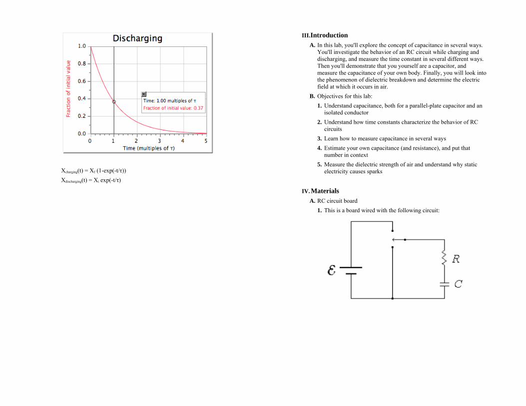
1. This is a board wired with the following circuit:

2. When the switch is in the up position, the battery is included in the circuit to charge the capacitor. When the switch is in the down position, the capacitor discharges through the resistor. When the switch is in the middle position, no current flows and any charge which happens to already be on the capacitor remains there.
3. The values of the components on the board are: R = 30 kΩ C = 1 μF The batterys are standard 1.5-volt AA cell batterys (with an emf of
roughly 1.6 volts). C. Several capacitors for use in the last part of the lab:
1. C1 = 100 pF This capacitor is the one which is stuck in a little plastic sheath:
This is so that you can handle it without accidentally discharging it through your fingers.
2. C2 = 0.11 μF This is a relatively large capacitor connected across a pair of banana plug sockets on a wooden board:
You will use this capacitor in conjunction with the charge sensor (see below). Do not connect this capacitor directly across the high-voltage power supply! It was not designed to handle high voltages.
3. C3 = ?? This is a variable capacitor made of a pair of thumbtacks help a small distance apart by a clothespin:
You can adjust its capacitance by turning the knob on the clothespin.
D. LabPro interface with differential voltage probe 1. The differential voltage probe is basically just a voltmeter. Like the
multimeter you used in Lab #1, it measures the potential at the red probe minus the potential at the black probe. You used this capability last week in Lab #2.
2. However, the Logger Pro software allows you to collect voltage data automatically. In particular, you can ask it to measure the voltage every few milliseconds and then display the voltage as a function of time. This capability will enable you to study circuits

where the voltages are changing in time, such as RC circuits. To collect data automatically, click on the green Collect button in the Logger Pro toolbar.
3. Remember that the differential voltage probe acts like a 10 MΩ resistor. So if you place it in parallel across a charged capacitor, the capacitor will slowly discharge through it.
E. Charge sensor 1. This is another probe that connects to the LabPro interface and can
be used to input data into Logger Pro.
It acts almost exactly like the differential voltage probe, except that its "internal resistance" is much higher, so that it won't discharge a capacitor while you are trying to measure its voltage. The downside is that the charge sensor has an internal time constant of 0.1 s, so you can't use it to measure anything that changes more rapidly than that.
2. Zeroing the charge sensor is slightly different from zeroing the differential voltage probe. First, short the leads of the charge sensor together. Then while they are shorted, press the button located on the charge sensor itself (not a software button in Logger Pro) and hold for about a second to zero. Then you can unshort the leads and measure something.
3. The charge sensor has three settings, controlled by a switch on the box. You should use the setting marked ±10 V. Even on this setting, the sensor is limited to about ±9 volts. If you attempt to put more than 9 volts across it, it will saturate. If this happens, be sure to zero the charge sensor before attempting to make another measurement.
4. The reason that this object is called a "charge sensor" rather than just a voltmeter is that it is intended to be connected across a large capacitor of known capacitance (in this case, C2 = 0.11 μF). Then by measuring the voltage across the capacitor, you can calculate how much charge is on it.
5. The charge sensor should always be used in conjunction with C2 (and vice versa). Just as C2 is not intended to support high voltages, neither is the charge sensor. Try not to put more than 10 volts across it.
F. High-voltage power supply (HVPS) 1. This is a DC power supply intended for use in the last part of the
lab. It maintains a very large voltage across its terminals; however, the current that it can supply is limited to under 10 μA (for safety reasons).
2. The black cable plugged into the "COM" terminal of the HVPS is connected to the building ground (and thence to the actual Earth itself). The red cable can be plugged into any of the three terminals marked 1000 V, 2000 V, or 3000 V (or also to the +30 V, but that would be boring—kilovolts are so much more interesting) depending on which voltage you need.
3. So if you plug the red banana cable into the 3000 V terminal, anything you bring into electrical contact with the red plug will be brought to 3 kV above ground. Likewise, to ground something (bring its potential down to zero), just touch it to the black plug in the COM terminal.
4. For convenience, the red and black banana cables are connected to two posts on a wooden board with wire exposed, so that you can easily ground any element of your circuit or bring something up to a high voltage.
G. Shims 1. These are three thin pieces of metal, labeled A, B, and C. You can
measure their thickness with calipers. 2. You can use these to estimate the distance between the thumbtacks
in Capacitor 3.

H. Dial caliper 1. A caliper is a device for measuring very small distances or
thicknesses:
2. The caliper has three measuring modes: outside jaws that you can
use to measure the thickness of something; inside jaws that you can use to measure the size of an opening (the inner diameter of a pipe, for instance); and a depth probe that you can use to measure the depth of a hole. The jaws can be moved with the thumb wheel until they fit the distance being measured. Then the linear scale along the caliper indicates the length roughly, and the dial indicates the length much more precisely.
3. For the calipers we will be using in the lab, the dial spins once every 2 mm, and the smallest tick mark on the dial corresponds to a change of 0.02 mm.
V. Procedure: Charging and discharging of a capacitor 1. Setup
a. Open the Logger Pro file Lab2.cmbl. The file has been set up for you so that you should be ready to collect data. When you click on the Collect button, it will collect data for 10 seconds and then automatically stop. Do not press the stop button while it is collecting.
b. Familiarize yourselves with the RC circuit board. Make sure you know which switch position does what (and which component is the resistor and which is the capacitor!). Note that if you charge the capacitor, it remains charged, even after you disconnect the battery, until you allow it to discharge.
2. Charging RC a. Start with the capacitor fully discharged. Connect the clip leads
of the differential voltage probe across the capacitor and click on Collect. When you see the message "Waiting for data," throw the switch into the charging position.
b. What results do you see? Is it what you expected? Try zooming in on the interesting regions of the graph. The easiest way to do this is by clicking and dragging to define a rectangle that you
want to zoom in on, and then clicking on the zoom in button. (1) What are the "initial" and "final" values of the capacitor
voltage?
(2) How long after you throw the switch does it take for the capacitor voltage to go 63% of the way from its initial to final values? (You will need to zoom in on the graph to answer this question well.)
(3) Is this consistent with the stated component values for R
and C?

(4) Curve fit this graph. Does it agree with theory? (Get a TF to help you with the fit if needed.)
(5) Include this graph with your lab write-up.
3. Discharging RC
a. With the capacitor fully charged, press collect and then when it says "Waiting for data," throw the switch to the discharging position. (1) You might notice a weird behavior here: when the capacitor
is charged and the switch is in the neutral (neither charging nor discharging) position, the capacitor voltage seems to very slowly decrease over time. This is because of the voltmeter itself—remember, it acts like a 10 MΩ resistor connected across the capacitor. So even when the rest of the circuit is disconnected, the capacitor can discharge through this large resistor.
What would be the time constant for this discharging? (This question is intended to be a calculation, not a measurement.)
(2) To minimize any error caused by this slow discharge, keep
the switch in the charging position until you are ready to throw it into the discharging position. It's okay if the voltage goes down a little bit before the discharging begins; the only difference is that it is as if the initial charge on the capacitor were somewhat lower.
b. How long does it take for the capacitor voltage to become 1/e of its initial value?
c. Is the time constant the same as it was for charging?
d. Curve fit this graph. Does it agree with theory? (Get a TF to
help you with the fit if needed.)
e. Include this graph with your write-up.
4. Save your Logger Pro file (file: save as: yourname.cmbl to location: desktop) before moving to the next part. At this point, you can put away the RC circuit board; you won't need to use it again.
C. Human capacitance 1. Are you a capacitor?
a. In this section, you'll use the high-voltage power supply (HVPS) to investigate capacitance. Make sure you are familiar with how it works (see the materials section above). The HVPS is not dangerous, but this section won't make any sense if you don't know how to ground something or charge it up to high voltage. Warning: if you have a pacemaker or other implanted electronic medical device, don't do any of these parts on yourself. Let your lab partners do all the shocking work. We don't actually think it will cause any damage, but there's no reason to take unnecessary risks.
b. Start by plugging the red plug of the HVPS into the +3000 V jack.
c. One thing we know about capacitors is that we can put a voltage across one and it will stay there until we discharge it. To demonstrate this, take capacitor C1 (the one in the plastic tube—not the one attached to the wooden posts), and clip one end of it to ground using an alligator lead. Taking care to only hold it using the plastic tube, touch the free end of the capacitor to +3 kV for a moment. Now bring the free end (which is now at +3 kV) near the grounded post and touch it to ground.
(1) What happens?
d. So C1 can be charged and then discharged. It's a capacitor—no surprise there. But you can do the same thing with your own body! First, ground yourself by touching the ground terminal of the HVPS. Then touch the +3 kV end and hold it for a second. Now go back and touch ground again. (1) What happens?
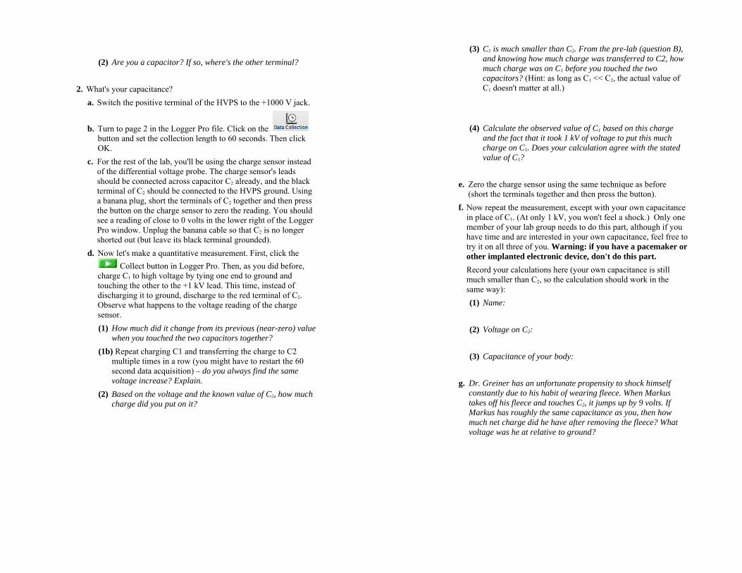
(2) Are you a capacitor? If so, where's the other terminal?
2. What's your capacitance?
a. Switch the positive terminal of the HVPS to the +1000 V jack.
b. Turn to page 2 in the Logger Pro file. Click on the button and set the collection length to 60 seconds. Then click OK.
c. For the rest of the lab, you'll be using the charge sensor instead of the differential voltage probe. The charge sensor's leads should be connected across capacitor C2 already, and the black terminal of C2 should be connected to the HVPS ground. Using a banana plug, short the terminals of C2 together and then press the button on the charge sensor to zero the reading. You should see a reading of close to 0 volts in the lower right of the Logger Pro window. Unplug the banana cable so that C2 is no longer shorted out (but leave its black terminal grounded).
d. Now let's make a quantitative measurement. First, click the Collect button in Logger Pro. Then, as you did before,
charge C1 to high voltage by tying one end to ground and touching the other to the +1 kV lead. This time, instead of discharging it to ground, discharge to the red terminal of C2. Observe what happens to the voltage reading of the charge sensor. (1) How much did it change from its previous (near-zero) value
when you touched the two capacitors together? (1b) Repeat charging C1 and transferring the charge to C2
multiple times in a row (you might have to restart the 60 second data acquisition) – do you always find the same voltage increase? Explain.
(2) Based on the voltage and the known value of C2, how much charge did you put on it?
(3) C1 is much smaller than C2. From the pre-lab (question B), and knowing how much charge was transferred to C2, how much charge was on C1 before you touched the two capacitors? (Hint: as long as C1 << C2, the actual value of C1 doesn't matter at all.)
(4) Calculate the observed value of C1 based on this charge and the fact that it took 1 kV of voltage to put this much charge on C1. Does your calculation agree with the stated value of C1?
e. Zero the charge sensor using the same technique as before
(short the terminals together and then press the button). f. Now repeat the measurement, except with your own capacitance
in place of C1. (At only 1 kV, you won't feel a shock.) Only one member of your lab group needs to do this part, although if you have time and are interested in your own capacitance, feel free to try it on all three of you. Warning: if you have a pacemaker or other implanted electronic device, don't do this part. Record your calculations here (your own capacitance is still much smaller than C2, so the calculation should work in the same way): (1) Name:
(2) Voltage on C2:
(3) Capacitance of your body:
g. Dr. Greiner has an unfortunate propensity to shock himself
constantly due to his habit of wearing fleece. When Markus takes off his fleece and touches C2, it jumps up by 9 volts. If Markus has roughly the same capacitance as you, then how much net charge did he have after removing the fleece? What voltage was he at relative to ground?
Try it yourself – take off a sweater, rub it over your hair, put it
away, and then touch the capacitor and see how the charge changes.
a. Calculate the potential difference that you have built up when you took off your sweater. (Hint: You can measure the voltage change on the 0.11 microfarad capacitor and you know your own capacitance.)
h. When you have completed this part, set aside C2 and the
charge sensor. You won't need them again, and using them in the next part may damage the equipment.
3. So now you know your capacitance. How much capacitance is that, anyway? a. First, a calculation: Imagine a solid conducting sphere with the
same capacitance (relative to a faraway ground) as your body. What would its radius be? How does this compare with your own length scale?
b. Now look at capacitor C3, made of a pair of thumbtacks stuck
into a clothespin. This is, roughly speaking, a parallel plate capacitor whose plates have an area of about 1 cm2. When the thumbtack heads are separated by 1 mm, C3 is on the order of 1 pF. At this separation, roughly how big would the thumbtacks have to be for C3 to have a capacitance comparable to your own?
c. Throughout this part of the lab, you've seen sparks fly. The
physical principle behind this phenomenon is that the sparks are due to the dielectric breakdown of air: air, like any dielectric, has a maximum electric field that it can support before it breaks down and becomes conducting. You can use the variable capacitor C3, as crude as it is, to investigate sparking more closely.
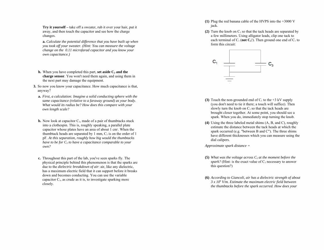
(1) Plug the red banana cable of the HVPS into the +3000 V jack.
(2) Turn the knob on C3 so that the tack heads are separated by a few millimeters. Using alligator leads, clip one tack to each terminal of C1 (not C2!). Then ground one end of C1 to form this circuit:
(3) Touch the non-grounded end of C1 to the +3 kV supply
(you don't need to tie it there; a touch will suffice). Then slowly turn the knob on C3 so that the tack heads are brought closer together. At some point, you should see a spark. When you do, immediately stop turning the knob.
(4) Using the three labeled metal shims (A, B, and C), roughly estimate the distance between the tack heads at which the spark occurred (e.g. "between B and C"). The three shims have different thicknesses which you can measure using the dial calipers.
Approximate spark distance =
(5) What was the voltage across C3 at the moment before the spark? (Hint: is the exact value of C3 necessary to answer this question?)
(6) According to Giancoli, air has a dielectric strength of about
3 x 10⁶ V/m. Estimate the maximum electric field between the thumbtacks before the spark occurred. How does your
calculation compare with Giancoli's? Name: ______________ Lab Day and Time: __________________
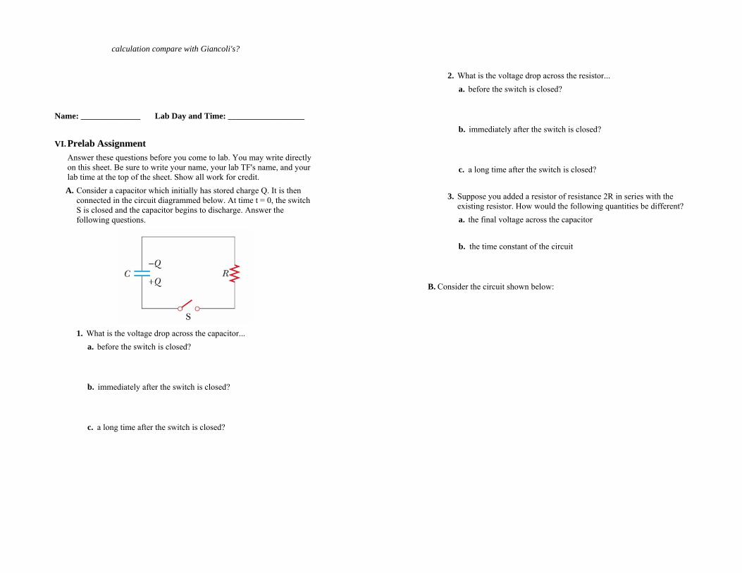
VI. Prelab Assignment Answer these questions before you come to lab. You may write directly on this sheet. Be sure to write your name, your lab TF's name, and your lab time at the top of the sheet. Show all work for credit. A. Consider a capacitor which initially has stored charge Q. It is then
connected in the circuit diagrammed below. At time t = 0, the switch S is closed and the capacitor begins to discharge. Answer the following questions.
1. What is the voltage drop across the capacitor...
a. before the switch is closed?
b. immediately after the switch is closed?
c. a long time after the switch is closed?
2. What is the voltage drop across the resistor... a. before the switch is closed?
b. immediately after the switch is closed?
c. a long time after the switch is closed?
3. Suppose you added a resistor of resistance 2R in series with the existing resistor. How would the following quantities be different? a. the final voltage across the capacitor
b. the time constant of the circuit
B. Consider the circuit shown below:

Initially, the switch S is in the down position, so that C2 is charged to voltage V0. Then the switch is thrown into the up position, so that the two capacitors are connected. You may assume that the wires in the circuit have small resistance. 1. Label the diagram with the charges on each plate of each capacitor
at the moment before the switch is flipped.
2. What are the charges on the capacitors a long time after the switch is flipped? (Hint: charge cannot jump the gap between one conductor and another.) ...the voltages?
3. What do your answers to the previous question reduce to if C2 is much less than C1? ...much bigger than C1?