3-Per Unit System.ppt - University of Hong Kongwork1104/3-Per Unit System.pdf · Per unit notation...
24
ELEC-1104 Lecture 3: Lecture 3: Per Unit Systems Per Unit Systems
Transcript of 3-Per Unit System.ppt - University of Hong Kongwork1104/3-Per Unit System.pdf · Per unit notation...
ELEC-1104
Lecture 3:Lecture 3:
Per Unit SystemsPer Unit Systems
Basic Units
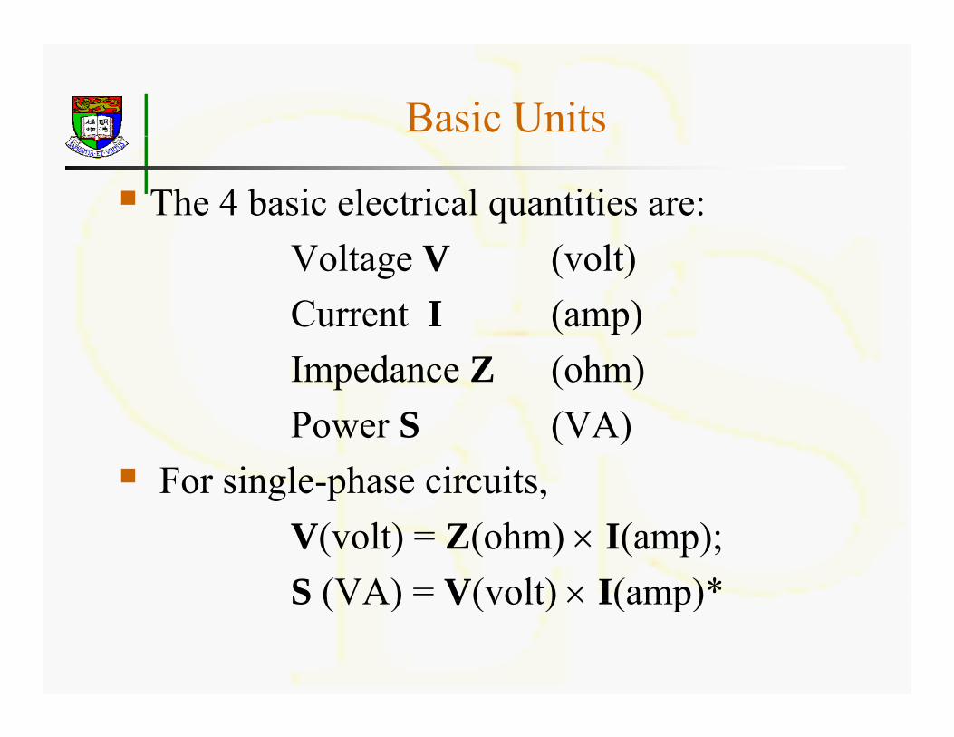
The 4 basic electrical quantities are:Voltage V (volt)Current I (amp)Current I (amp)Impedance Z (ohm)P S (VA)Power S (VA)
For single-phase circuits,V(volt) = Z(ohm) × I(amp);S (VA) = V(volt) × I(amp)*S (VA) V(volt) × I(amp)
Per unit notation
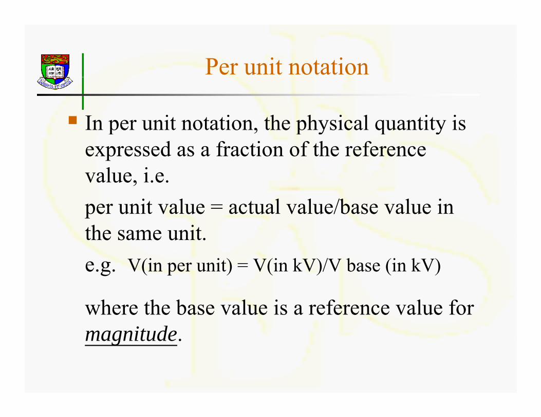
In per unit notation, the physical quantity isIn per unit notation, the physical quantity is expressed as a fraction of the reference value, i.e.va ue, .e.per unit value = actual value/base value in the same unitthe same unit.e.g. V(in per unit) = V(in kV)/V base (in kV)
where the base value is a reference value for magnitude.magnitude.
Base QuantitiesQ
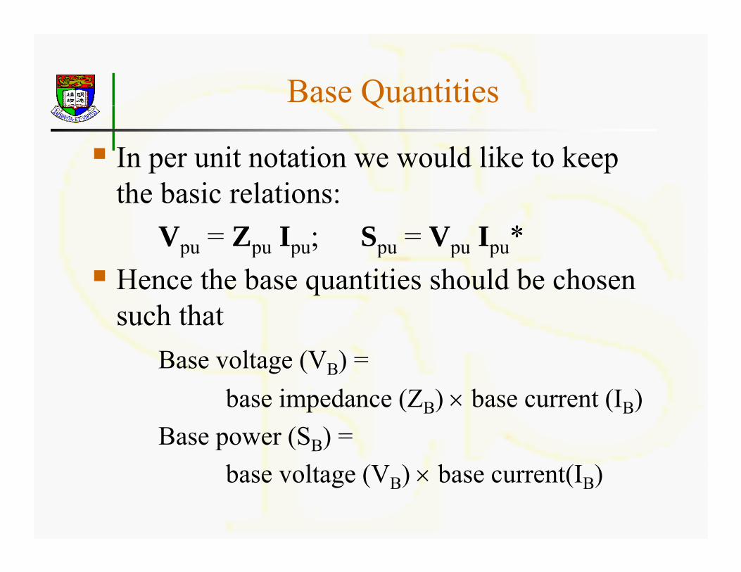
In per unit notation we would like to keep the basic relations:
Vpu = Zpu Ipu; Spu = Vpu Ipu*pu pu pu; pu pu pu
Hence the base quantities should be chosen such thatsuch that
Base voltage (VB) = b i d (Z ) b t (I )base impedance (ZB) × base current (IB)
Base power (SB) = b l (V ) b (I )base voltage (VB) × base current(IB)

Base QuantitiesQ
Thus only two of the base quantities can beThus only two of the base quantities can be arbitrarily chosen, the other two will follow directly.d ect y.It is common practice to specify
b (S ) d b lt (V )base pwer (SB) and base voltage (VB)Then it follows
base current IB = SB/VB
base impedance ZB = VB/IB =VB2/SBp B B B B B
Percentage Valuesg
An equivalent way to express the per unitAn equivalent way to express the per unit value is the percentage value where
Percentage value = per unit value × 100%
However, percentage values are not so convenient to use sinceconvenient to use since
Vpercent ≠ Zpercent × Ipercent
Example 1p
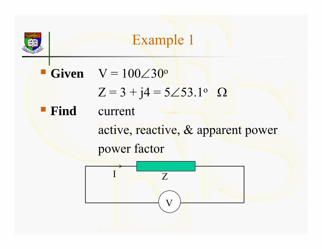
Given V = 100∠30oGiven V 100∠30Z = 3 + j4 = 5∠53.1o Ω
Fi d tFind currentactive, reactive, & apparent powerpower factor
I ZI
VV
Solution 1
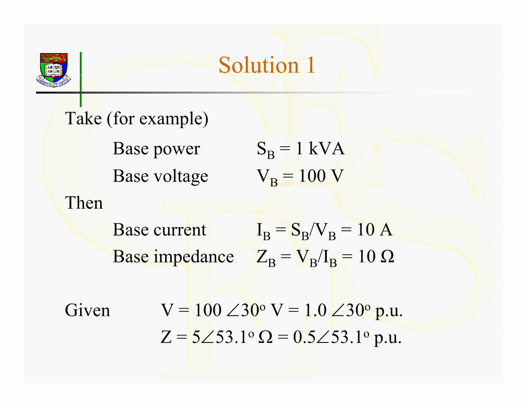
Take (for example)( p )Base power SB = 1 kVA Base voltage V = 100 VBase voltage VB 100 V
ThenBase current I = S /V = 10 ABase current IB = SB/VB = 10 ABase impedance ZB = VB/IB = 10 Ω
Given V = 100 ∠30o V = 1.0 ∠30o p.u.Z 5∠53 1o Ω 0 5∠53 1oZ = 5∠53.1o Ω = 0.5∠53.1o p.u.
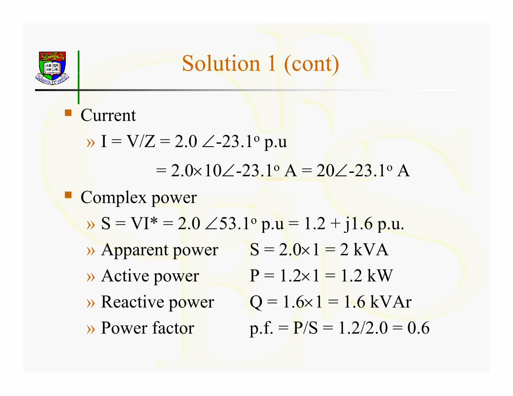
Solution 1 (cont)( )
Current» I = V/Z = 2.0 ∠-23.1o p.u
= 2 0×10∠-23 1o A = 20∠-23 1o A 2.0×10∠ 23.1 A 20∠ 23.1 AComplex power» S = VI* = 2 0 ∠53 1o p u = 1 2 + j1 6 p u» S = VI* = 2.0 ∠53.1o p.u = 1.2 + j1.6 p.u.» Apparent power S = 2.0×1 = 2 kVA
Acti e po er P 1 2×1 1 2 kW» Active power P = 1.2×1 = 1.2 kW» Reactive power Q = 1.6×1 = 1.6 kVAr
P f t f P/S 1 2/2 0 0 6» Power factor p.f. = P/S = 1.2/2.0 = 0.6
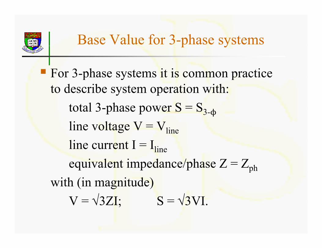
Base Value for 3-phase systemsp y
For 3-phase systems it is common practiceFor 3 phase systems it is common practice to describe system operation with:
total 3-phase power S = Stotal 3-phase power S = S3-
line voltage V = Vline
line current I = Iline
equivalent impedance/phase Z = Zphp
with (in magnitude)V = √3ZI; S = √3VIV √3ZI; S √3VI.
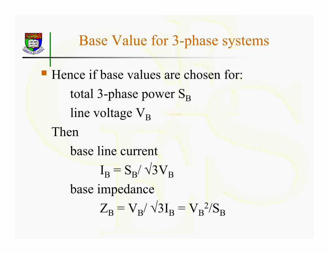
Base Value for 3-phase systemsp y
Hence if base values are chosen for:Hence if base values are chosen for:total 3-phase power SB
li lt Vline voltage VB
Thenbase line current
IB = SB/ √3VBB SB √ VB
base impedance Z V / √3I V 2/SZB = VB/ √3IB = VB
2/SB
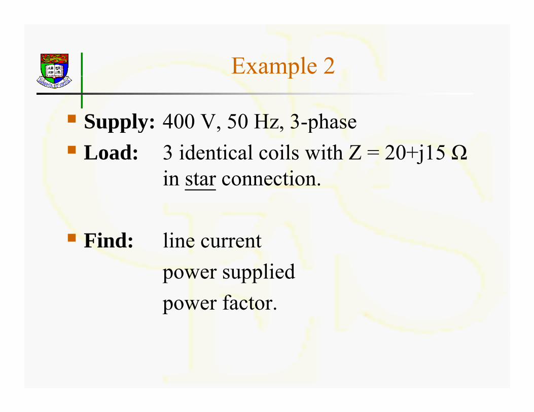
Example 2p
Supply: 400 V, 50 Hz, 3-phaseSupply: 400 V, 50 Hz, 3 phaseLoad: 3 identical coils with Z = 20+j15 Ω
in star connectionin star connection.
Find: line currentpower suppliedpower factor.

Solution 2
Take (for example)( p )Base power (total 3-phase) SB = 10 kVABase voltage (line-to-line) V = 400 VBase voltage (line-to-line) VB 400 V
ThenBase current I = S /√3V = 14 43 ABase current IB = SB/√3VB = 14.43 ABase impedance ZB = VB
2/SB = 16 Ω
Given V = 400 V = 1.0 p.u.Z 25∠36 9o Ω 1 5625∠36 9oZ = 25∠36.9o Ω = 1.5625∠36.9o p.u.
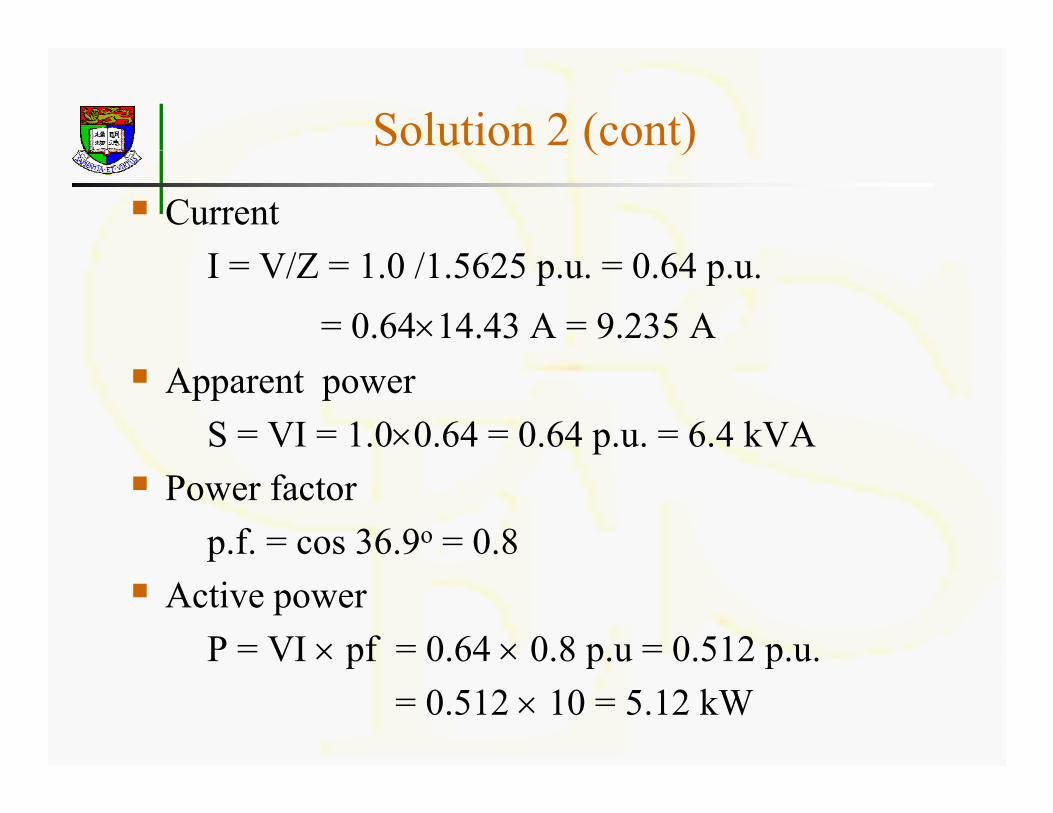
Solution 2 (cont)( )
Current/ 1 0 /1 62 0 64I = V/Z = 1.0 /1.5625 p.u. = 0.64 p.u.
= 0.64×14.43 A = 9.235 AApparent power
S = VI = 1.0×0.64 = 0.64 p.u. = 6.4 kVAPower factor
p.f. = cos 36.9o = 0.8pActive power
P = VI × pf = 0.64 × 0.8 p.u = 0.512 p.u.p p p= 0.512 × 10 = 5.12 kW
Choice of Base values
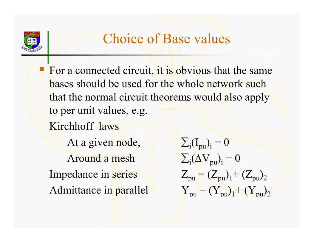
For a connected circuit, it is obvious that the same ,bases should be used for the whole network such that the normal circuit theorems would also apply to per unit values, e.g.Kirchhoff laws
At a given node, ∑i(Ipu)i = 0Around a mesh ∑i(ΔVpu)i = 0
Impedance in series Zpu = (Zpu)1+ (Zpu)2
Admittance in parallel Ypu = (Ypu)1+ (Ypu)2

Base values for a transformer
In a transformer, two circuits are not directlyIn a transformer, two circuits are not directly connected but magnetically coupled. The voltages of the windings are in the ratio of vo tages o t e w d gs a e t e at o oturns and currents in inverse ratio.
For the coupled circuit we should then chooseFor the coupled circuit, we should then choose» The same base power» Base voltages in the ratio of turns» Base voltages in the ratio of turns.
This will ensure Spu, Vpu, Ipu, to remain unchanged when passing through an ideal transformerwhen passing through an ideal transformer
Base values for a transformer
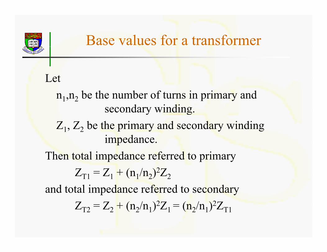
LetLet n1,n2 be the number of turns in primary and
secondary windingsecondary winding.Z1, Z2 be the primary and secondary winding
impedance.impedance.Then total impedance referred to primary
Z 1 = Z1 + (n1/n2)2Z2ZT1 Z1 + (n1/n2) Z2
and total impedance referred to secondaryZ = Z + (n /n )2Z = (n /n )2ZZT2 = Z2 + (n2/n1)2Z1 = (n2/n1)2ZT1
Base values for a transformer
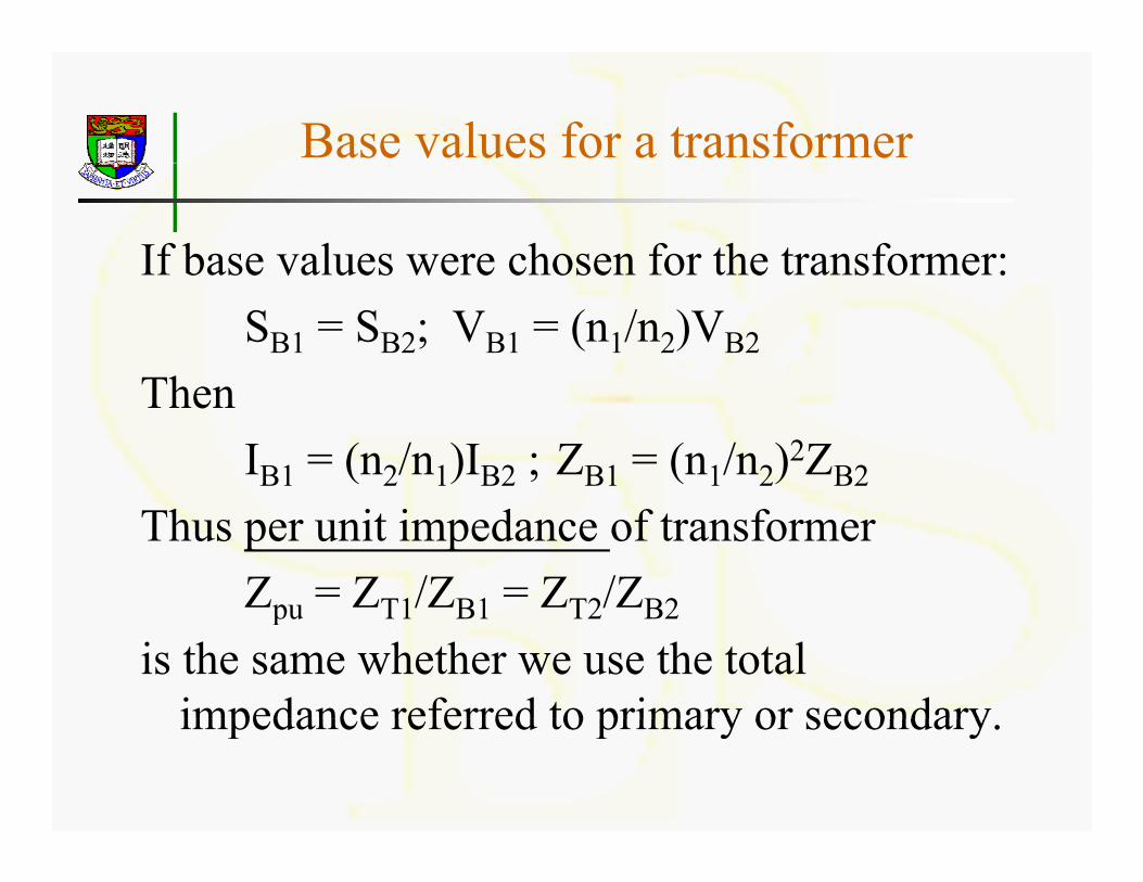
If base values were chosen for the transformer:If base values were chosen for the transformer:SB1 = SB2; VB1 = (n1/n2)VB2
ThThenIB1 = (n2/n1)IB2 ; ZB1 = (n1/n2)2ZB2
Thus per unit impedance of transformerZpu = ZT1/ZB1 = ZT2/ZB2pu T1 B1 T2 B2
is the same whether we use the total impedance referred to primary or secondaryimpedance referred to primary or secondary.
Equivalent circuit for transformerq
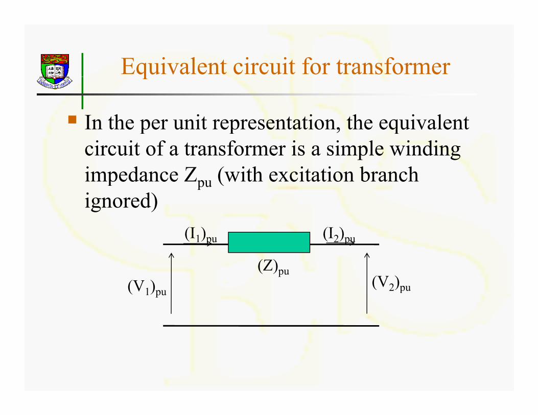
In the per unit representation, the equivalentIn the per unit representation, the equivalent circuit of a transformer is a simple winding impedance Zpu (with excitation branch peda ce pu (w t e c tat o b a cignored)
(I ) (I )
(V ) (V2)pu
(I1)pu (I2)pu
(Z)pu(V1)pu
(V2)pu

Base Conversion
If the per unit values are given based on SB1If the per unit values are given based on SB1and VB1 which are different from the chosen base SB2 and VB2 for analysis, the given per base SB2 a d VB2 o a a ys s, t e g ve peunit values must be modified before they can be used. Thusc be used. us
(Vpu)2 = V/VB2 = (Vpu)1×VB1/VB2
(Spu)2 = S/SB2 = (Spu)1×SB1/SB2
Base Conversion
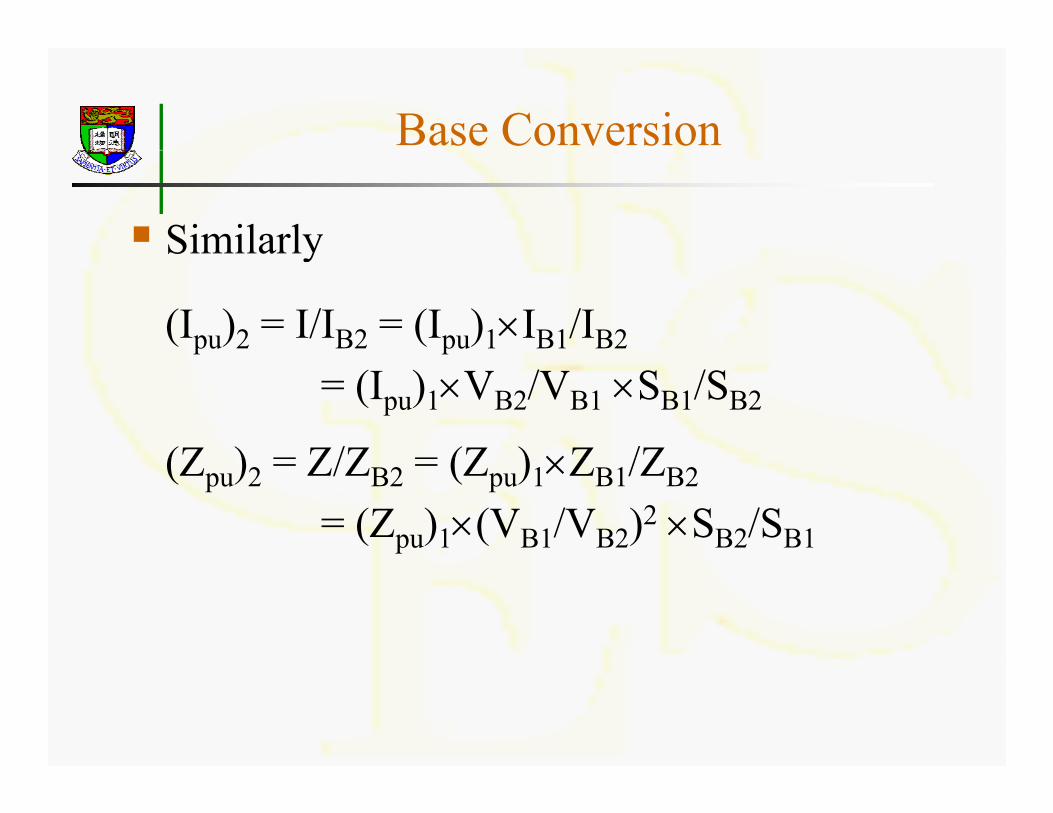
SimilarlySimilarly
(Ipu)2 = I/IB2 = (Ipu)1×IB1/IB2
= (Ipu)1×VB2/VB1 ×SB1/SB2
(Z ) = Z/Z = (Z ) ×Z /Z(Zpu)2 = Z/ZB2 = (Zpu)1×ZB1/ZB2
= (Zpu)1×(VB1/VB2)2 ×SB2/SB1
Examplep
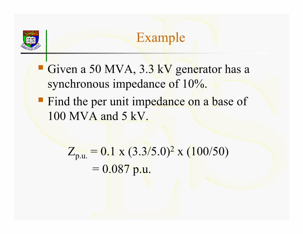
Given a 50 MVA, 3.3 kV generator has aGiven a 50 MVA, 3.3 kV generator has a synchronous impedance of 10%.Find the per unit impedance on a base ofFind the per unit impedance on a base of 100 MVA and 5 kV.
Zp.u. = 0.1 x (3.3/5.0)2 x (100/50)= 0.087 p.u.
Examplep
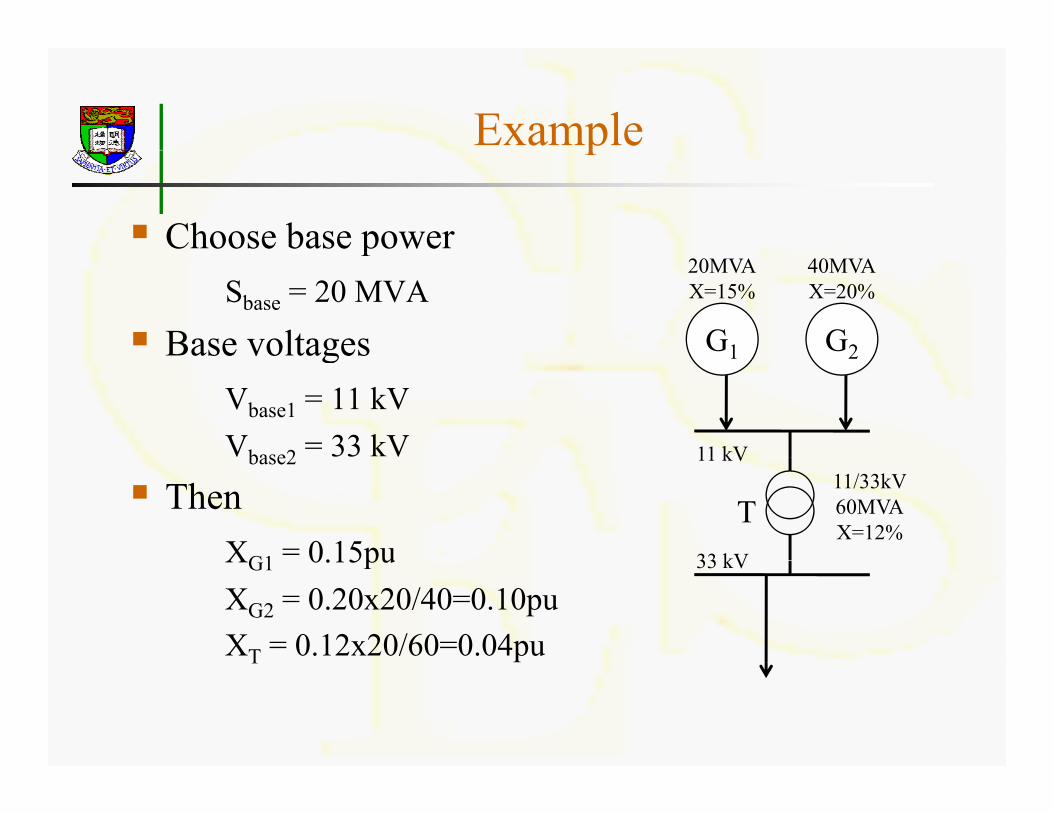
Choose base powerpSbase = 20 MVA
Base voltages G1 G2
20MVAX=15%
40MVAX=20%
ase vo tagesVbase1 = 11 kVVbase2 = 33 kV
1 2
11 kVbase2
ThenXG1 = 0.15pu
11/33kV60MVAX=12%
11 kV
33 kV
TXG1 0.15puXG2 = 0.20x20/40=0.10puXT = 0.12x20/60=0.04pu
33 kV
T
Advantages of Per Unit Systemg y
Normally we are dealing with numericsNormally we are dealing with numerics near unity rather than over a wide range.Provides a more meaningful comparison ofProvides a more meaningful comparison of parameters of machines with different ratingsratings.As the per unit values of parameters of a
hi f i d i ll f llmachine of a given design normally falls within a certain range, a typical value can be sed if s ch parameters are not pro idedbe used if such parameters are not provided.