3 LUBRICATION SYSTEM - Freightliner Trucks · · 2013-04-023 LUBRICATION SYSTEM ... Figure 3-4...
38
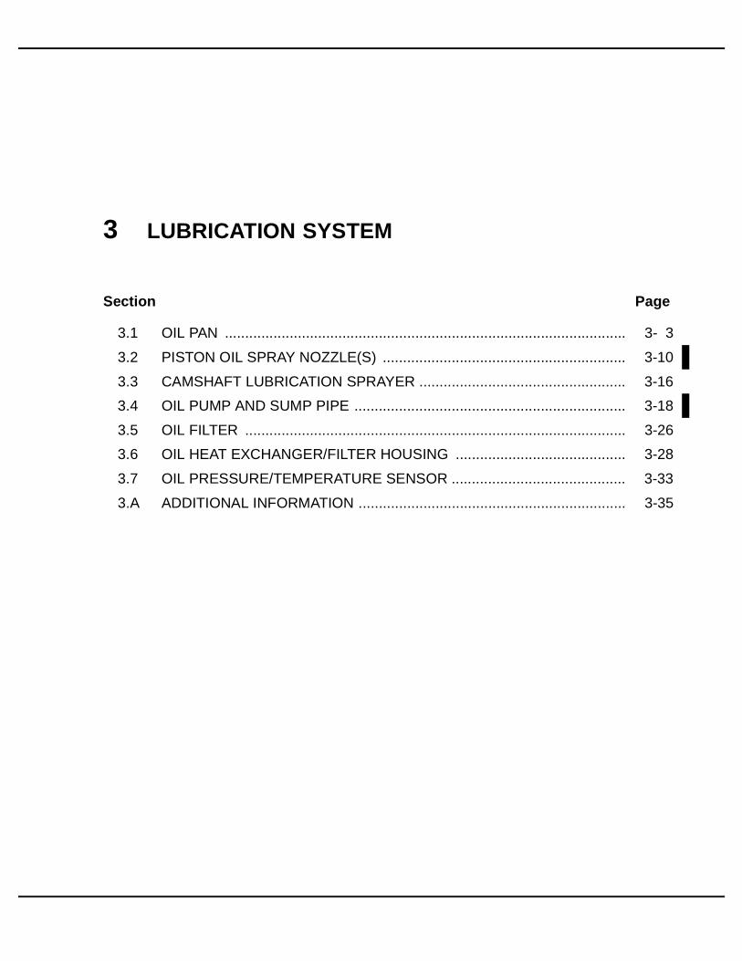
3 LUBRICATION SYSTEM Section Page 3.1 OIL PAN ................................................................................................... 3- 3 3.2 PISTON OIL SPRAY NOZZLE(S) ............................................................ 3-10 3.3 CAMSHAFT LUBRICATION SPRAYER ................................................... 3-16 3.4 OIL PUMP AND SUMP PIPE ................................................................... 3-18 3.5 OIL FILTER .............................................................................................. 3-26 3.6 OIL HEAT EXCHANGER/FILTER HOUSING .......................................... 3-28 3.7 OIL PRESSURE/TEMPERATURE SENSOR ........................................... 3-33 3.A ADDITIONAL INFORMATION .................................................................. 3-35
Transcript of 3 LUBRICATION SYSTEM - Freightliner Trucks · · 2013-04-023 LUBRICATION SYSTEM ... Figure 3-4...
3 LUBRICATION SYSTEM
Section Page
3.1 OIL PAN ................................................................................................... 3- 3
3.2 PISTON OIL SPRAY NOZZLE(S) ............................................................ 3-10
3.3 CAMSHAFT LUBRICATION SPRAYER ................................................... 3-16
3.4 OIL PUMP AND SUMP PIPE ................................................................... 3-18
3.5 OIL FILTER .............................................................................................. 3-26
3.6 OIL HEAT EXCHANGER/FILTER HOUSING .......................................... 3-28
3.7 OIL PRESSURE/TEMPERATURE SENSOR ........................................... 3-33
3.A ADDITIONAL INFORMATION .................................................................. 3-35

(Rev. 0403) All information subject to change without notice.
3-2 From Bulletin 5–MBE4000–05 6SE412 0403 Copyright © 2005 DETROIT DIESEL CORPORATION

MBE4000 SERVICE MANUAL
3.1 OIL PAN
Perform the following procedures for removal and installation of the oil pan.
3.1.1 Oil Pan Removal
Remove the oil pan as follows:
1. Drain the engine oil. See Figure 3-1 for location of the drain plug. Discard the drainplug seal.
Figure 3-1 Engine Oil Drain Plug
PERSONAL INJURY
To avoid injury when removing or installing a heavy enginecomponent, ensure the component is properly supportedand securely attached to an adequate lifting device toprevent the component from falling.
2. Using a floor jack, jack up the vehicle and place it on stands located behind the frontsuspension.
3. Loosen all front suspension shackle bolts.
4. Remove the front spring bolts and shock absorber bolts. Using the floor jack, lower theaxle to the ground.
All information subject to change without notice. (Rev. 0403)
6SE412 0403 Copyright © 2005 DETROIT DIESEL CORPORATION From Bulletin 5–MBE4000–05 3-3

3.1 OIL PAN
5. Remove the dipstick and dipstick O-ring. Discard the O-ring. See Figure 3-2.
1. Dipstick 11. Fill Tube Retainer Washer
2. Dipstick O-ring 12. Oil Pan
3. Dipstick Guide Tube 13. Oil Pan Gasket
4. Adaptor 14. Oil Pan Bolt
5. Adaptor Seal 15. Drain Plug Seal
6. Oil Fill Cap 16. Oil Pan Drain Plug
7. Oil Fill O-ring 17. Fill Tube Gasket
8. Oil Fill Tube 18. Fill Tube Flatwasher
9. Oil Fill Tube Retainer 19. Fill Tube Bolt
10. Oil Fill Retainer Bolt
Figure 3-2 Oil Pan Removal and Installation
(Rev. 0403) All information subject to change without notice.
3-4 From Bulletin 5–MBE4000–05 6SE412 0403 Copyright © 2005 DETROIT DIESEL CORPORATION

MBE4000 SERVICE MANUAL
6. Remove the connector and clamp attaching the dipstick guide tube to the oil fill tube.See Figure 3-3.
1. Dipstick 5. Connector
2. Oil Fill Cap 6. Dipstick Clamp
3. Locknut 7. Oil Fill Tube Clamp
4. Flatwasher 8. Bolt
Figure 3-3 Standoff Bracket (exploded view)
7. Remove the dipstick guide tube, adaptor, and seal. Clean the guide tube and discardthe seal. See Figure 3-2.
8. Remove the oil fill tube.
[a] Remove the bolt that fastens the oil fill tube retainer to the cylinder block.
[b] Remove the oil fill bolts and washers that fasten the oil fill tube to the oil pan. Savethe bolts and washers.
[c] Remove and discard the gasket on the oil fill tube. Clean the contact surfaces of thefill tube and the oil pan, removing all traces of gasket material.
[d] Clean the oil fill tube.
9. Remove the oil pan from the cylinder block.
10. Remove and discard the oil pan gasket. Save the bolts.
11. Thoroughly clean the pan. Remove all traces of gasket material from the pan and fromthe block.
3.1.2 Oil Pan Installation
Install the oil pan as follows:
1. Position a new gasket on the cylinder block.
All information subject to change without notice. (Rev. 0403)
6SE412 0403 Copyright © 2005 DETROIT DIESEL CORPORATION From Bulletin 5–MBE4000–05 3-5

3.1 OIL PAN
2. Install the pan on the block and tighten each oil pan bolt to 35 N·m (26 lb·ft). See Figure3-4 for the tightening pattern. When all the bolts have been tightened, go back andre-tighten the four corner bolts (positions #1 through #4).
Figure 3-4 Oil Pan Bolt Tightening Pattern
(Rev. 0403) All information subject to change without notice.
3-6 From Bulletin 5–MBE4000–05 6SE412 0403 Copyright © 2005 DETROIT DIESEL CORPORATION

MBE4000 SERVICE MANUAL
3. Install the oil fill tube as follows: (See Figure 3-5.)
1. Dipstick 6. Dipstick Clamp
2. Oil Fill Tube 7. Bolt
3. Locknut 8. Oil Fill Tube Clamp
4. Flatwasher 9. Oil Fill Tube Retainer
5. Connector Bracket
Figure 3-5 Installing the Oil Fill Tube and Dipstick Guide Tube
[a] Connect the oil fill tube clamp to the coolant inlet pipe using the oil fill tube clampbolt. Tighten to 10 N·m (7 lb·ft).
[b] Position a new oil fill tube gasket on the oil pan. See Figure 3-2.
[c] Install the three oil fill tube bolts. Tighten each bolt to 25 N·m (18 lb·ft).
[d] Tighten the oil fill tube clamp bolt to 25 N·m (18 lb·ft).
[e] Replace the O-ring in the oil fill cap. See Figure 3-2.
4. Replace the adaptor seal on the adaptor. Install the adaptor on the oil pan. Tighten theadaptor to 50 N·m (37 lb·ft). See Figure 3-2.
5. Install the dipstick guide tube on the adaptor and tighten it to 20 N·m (15 lb·ft).
NOTE:Check the alignment between the dipstick guide tube and the oil fill tube. They mustbe parallel to each other.
6. Replace the O-ring on the dipstick.
7. Replace the seal on the oil drain plug. Install the oil drain plug on the oil pan. Tighten thedrain plug to 80 N·m (59 lb·ft).
All information subject to change without notice. (Rev. 0403)
6SE412 0403 Copyright © 2005 DETROIT DIESEL CORPORATION From Bulletin 5–MBE4000–05 3-7

3.1 OIL PAN
8. Install dipstick clamp, oil fill tube clamp, and connector bracket. Tighten to 10 N·m(7 lb·ft). See Figure 3-5.
NOTE:Check the alignment between the dipstick guide tube and the oil fill tube. They mustbe parallel to each other.
9. Tighten the connector bracket locknuts until firm.
NOTE:Recheck the alignment between dipstick guide tube and oil fill tube.
10. Fill the engine oil circuit. The correct oil fill capacity is listed in Table 3-4.
11. Using the floor jack, raise the axle until it is in position to install the spring bolts and shockabsorber bolts. Install the front suspension.
12. Tighten the shackle bolts and adjust the suspension.
13. Remove the stands and lower the vehicle to the ground.
PERSONAL INJURY
Diesel engine exhaust and some of its constituents areknown to the State of California to cause cancer, birthdefects, and other reproductive harm.□ Always start and operate an engine in a well ventilated
area.□ If operating an engine in an enclosed area, vent the
exhaust to the outside.□ Do not modify or tamper with the exhaust system or
emission control system.
14. Start the engine and check for leaks.
(Rev. 0403) All information subject to change without notice.
3-8 From Bulletin 5–MBE4000–05 6SE412 0403 Copyright © 2005 DETROIT DIESEL CORPORATION

MBE4000 SERVICE MANUAL
15. Shut down the engine. Check the oil level and add oil if necessary. See Figure 3-6.
1. Maximum Fill Level 2. Minimum Fill Level
Figure 3-6 Oil Dipstick
NOTE:Do not fill beyond the maximum fill level on the dipstick, since overfilling may resultin high oil consumption.
All information subject to change without notice. (Rev. 0403)
6SE412 0403 Copyright © 2005 DETROIT DIESEL CORPORATION From Bulletin 5–MBE4000–05 3-9

3.2 PISTON OIL SPRAY NOZZLE(S)
3.2 PISTON OIL SPRAY NOZZLE(S)
Perform the following procedures for removal and installation of the piston oil spray nozzle.
3.2.1 Piston Oil Spray Nozzle(s) Removal
Remove the piston oil spray nozzle(s) as follows:
NOTE:These procedures refer to bolt-on piston oil spray nozzles only.
1. Remove the oil pan. Refer to section 3.1.1.
2. Remove the inspection cover on the flywheel housing and install the engine cranking tool(J–46167). See Figure 3-7. Rotate the crankshaft to gain access to the nozzle(s).
1. Inspection Cover
Figure 3-7 Installing the Engine Cranking Tool
(Rev. 0403) All information subject to change without notice.
3-10 From Bulletin 5–MBE4000–05 6SE412 0403 Copyright © 2005 DETROIT DIESEL CORPORATION

MBE4000 SERVICE MANUAL
3. Remove the hollow-core bolt that attaches each piston oil spray nozzle to the underside ofthe cylinder block. Remove the oil spray nozzle from the engine. See Figure 3-8.
1. Piston Spray Nozzle 2. Hollow Core Bolt
Figure 3-8 Removing the Piston Oil Spray Nozzle(s)
NOTE:Piston cooling nozzle tool J–47301 is used to check the proper alignment of the piston oilspray nozzles for non-EGR and EGR engines built before March 2005. EGR enginesbuilt starting March 2005 do not use this tool. For identification of the oil spray nozzlessee Figure 3-9.
All information subject to change without notice. (Rev. 0403)
6SE412 0403 Copyright © 2005 DETROIT DIESEL CORPORATION From Bulletin 5–MBE4000–05 3-11

3.2 PISTON OIL SPRAY NOZZLE(S)
Figure 3-9 Piston Cooling Nozzles
(Rev. 0403) All information subject to change without notice.
3-12 From Bulletin 5–MBE4000–05 6SE412 0403 Copyright © 2005 DETROIT DIESEL CORPORATION

MBE4000 SERVICE MANUAL
4. For non-EGR and EGR engine built before March 2005, check the piston oil spraynozzle(s) using the piston cooling jet tool (J–47301). See Figure 3-10.
1. Knurled Bolt 3. Setting Rod
2. Piston Oil Spray Nozzle 4. Setting Device
Figure 3-10 Checking the Piston Oil Spray Nozzle(s)
[a] Secure the setting device (part of toolset J–47301) in a vise with protective jaws.
[b] Remove the knurled bolt and setting rod from the setting device. Install the pistonoil spray nozzle on the setting device. Hand tighten the knurled bolt enough to holdthe nozzle firmly.
[c] Insert the correct end of the setting rod through the base of the setting device and intothe tip of the piston oil spray nozzle. If the setting rod will not insert into the tip ofthe piston oil cooling nozzle, discard the nozzle and replace with a new nozzle.
NOTE:The setting rod is double ended, one end has a diameter of 2.6 mm (0.102 in.) fornon-EGR engines and the other end is 3.0 mm (0.118 in.) for EGR engines.
All information subject to change without notice. (Rev. 0403)
6SE412 0403 Copyright © 2005 DETROIT DIESEL CORPORATION From Bulletin 5–MBE4000–05 3-13

3.2 PISTON OIL SPRAY NOZZLE(S)
3.2.2 Piston Oil Spray Nozzle(s) Installation
Install the piston oil spray nozzle(s) as follows:
1. Install each piston oil spray nozzle in the block with the locator pin correctly installed.See Figure 3-11. Tighten the hollow-core bolt to 40 N·m (30 lb·ft).
1. Pin Seat 2. Locator Pin
Figure 3-11 Installing the Piston Oil Spray Nozzle(s)
NOTE:The locator pin on the base of the piston oil spray nozzle must be inserted into the pinseat in the cylinder block until it engages.
NOTICE:
For EGR engines built March 2005 and later, the piston oil spraynozzle must be aligned to the center of the oil lubricating holein the bottom of the piston. If the nozzle is not properly aligned,inadequate lubrication to the piston will result in the failure of theengine.
2. For EGR engines built March 2005 and later check to ensure that the piston oil spraynozzle(s) are aligned with the oil hole in the base of the piston as follows:
[a] Bar the engine until the piston is at bottom dead center and check that the alignmentof the oil spray nozzle tip is in the center of the piston oil lubricating hole. Thenozzle should be inside the piston oil hole and centered.
[b] If the oil spray nozzle does not align in the center of the piston oil lubricating hole oris not inside the oil hole in the piston, replace the nozzle. Do not bend the nozzlesto align.
3. Install the oil pan. Refer to section 3.1.2.
(Rev. 0403) All information subject to change without notice.
3-14 From Bulletin 5–MBE4000–05 6SE412 0403 Copyright © 2005 DETROIT DIESEL CORPORATION

MBE4000 SERVICE MANUAL
4. Remove the engine cranking tool (J–46167) and install the the inspection cover. Torquebolts on cover to 25 N·m (18 lb·ft)See Figure 3-12.
1. Inspection Cover
Figure 3-12 Installing the Engine Cranking Tool
5. Fill the crankcase to the specified oil level listed in Table 3-4. Do not overfill the crankcase.
All information subject to change without notice. (Rev. 0403)
6SE412 0403 Copyright © 2005 DETROIT DIESEL CORPORATION From Bulletin 5–MBE4000–05 3-15

3.3 CAMSHAFT LUBRICATION SPRAYER
3.3 CAMSHAFT LUBRICATION SPRAYER
The six lubrication sprayers are located internally in the upper portion of the cylinder block nearthe camshaft and have a guide pin for proper location during installation.
The EPA 98 (non-EGR) engine has one drilled oil passage hole in the lubrication sprayer – it isused to spray oil on the injector unit pump camshaft lobe. The lubrication sprayer for the EPA 04(EGR) engine has three drilled oil passage holes – they are used to spray oil on the camshaft lobesfor the injector pump, intake cam followers, and exhaust cam followers. See Figure 3-13.
1. Oil Passages
Figure 3-13 Camshaft Lubrication Sprayer
3.3.1 Camshaft Lubrication Sprayer Removal
Remove the camshaft lubrication sprayer(s) as follows:
1. Remove the oil pan. Refer to section 3.1.1.
(Rev. 0403) All information subject to change without notice.
3-16 From Bulletin 5–MBE4000–05 6SE412 0403 Copyright © 2005 DETROIT DIESEL CORPORATION

MBE4000 SERVICE MANUAL
2. Remove the inspection cover on the flywheel housing and install the engine crankingtool (J–46167). See Figure 3-14. Rotate the crankshaft to gain access to the lubricationsprayer(s).
1. Inspection Cover
Figure 3-14 Installing the Engine cranking Tool
3. Remove the hollow-core bolt holding the sprayer in place.
4. Remove the camshaft lubrication sprayer(s).
5. Clean any clogged holes with solvent.
3.3.2 Camshaft Lubrication Sprayer Installation
Install the camshaft lubrication sprayer(s) as follows:
1. Align the guide pin on the lubrication sprayer with the hole in the block and secure withhollow-core bolt.
2. Torque the hollow-core bolt to 20 N·m (15 lb·ft).
3. Remove the engine cranking tool (J–46167) and install the the inspection cover. Torquebolts on cover to 25 N·m (18 lb·ft). See Figure 3-14.
4. Install the oil pan. Refer to section 3.1.2.
5. Fill the crankcase to the specified oil level. Do not overfill the crankcase. The correct oilfill capacity is listed in Table 3-4.
All information subject to change without notice. (Rev. 0403)
6SE412 0403 Copyright © 2005 DETROIT DIESEL CORPORATION From Bulletin 5–MBE4000–05 3-17

3.4 OIL PUMP AND SUMP PIPE
3.4 OIL PUMP AND SUMP PIPE
In the EPA 04 (EGR) engine, there are minor changes to the oil pump. The EGR engine has ahigher oil output now. There are larger internal gears compared to the EPA 98 (non-EGR) versionwhich has smaller internal gears. See Figure 3-15.
Figure 3-15 Comparison on Oil Pump Internal Gears
The mounting point location on the EGR engine oil sump pipe is 3.0 mm (0.118 in.) longer inlength than the non-EGR sump pipe. The removal and installation procedures are the same for thenon-EGR and EGR engine. See Figure 3-16.
Figure 3-16 Oil Pick Up Tube in the EPA 04 (EGR) Engine
Perform the following procedures for removal of the oil pump.
(Rev. 0403) All information subject to change without notice.
3-18 From Bulletin 5–MBE4000–05 6SE412 0403 Copyright © 2005 DETROIT DIESEL CORPORATION

MBE4000 SERVICE MANUAL
3.4.1 Oil Pump and Sump Pipe Removal
Remove the oil pump assembly as follows:
1. Remove the oil pan from the cylinder block. Refer to section 3.1.1.
2. Remove the sump pipe from the oil pump. See Figure 3-17.
[a] Remove the bolt attaching the sump pipe bracket to the cylinder block.
[b] Remove the two bolts attaching the sump pipe to the oil pump. Discard the gasket.
[c] Remove the sump pipe and bracket from the oil pump.
3. Remove the bolts attaching the pressure limiting valve to the oil pump and lower edge ofthe cylinder block. Remove the pressure limiting valve from the oil pump. See Figure3-17.
1. Valve Mounting Bolt 6. Sump Pipe Mounting Bolt
2. Pressure Limiting Valve 7. Sump Pipe
3. Oil Pump 8. Bracket
4. Oil Pump Mounting Bolt 9. Bracket Mounting Bolt
5. Gasket
Figure 3-17 Oil Pump and Sump Pipe Removal
4. Remove the bolt attaching the oil pump to the cylinder block. Remove the oil pump fromthe the cylinder block. See Figure 3-17.
5. Thoroughly clean the contact surfaces of the oil pump and cylinder block.
All information subject to change without notice. (Rev. 0403)
6SE412 0403 Copyright © 2005 DETROIT DIESEL CORPORATION From Bulletin 5–MBE4000–05 3-19
3.4 OIL PUMP AND SUMP PIPE
3.4.2 Oil Pump Disassembly
Disassemble the oil pump unit as follows:
1. Remove the oil pump from the cylinder block. Refer to section 3.4.1.
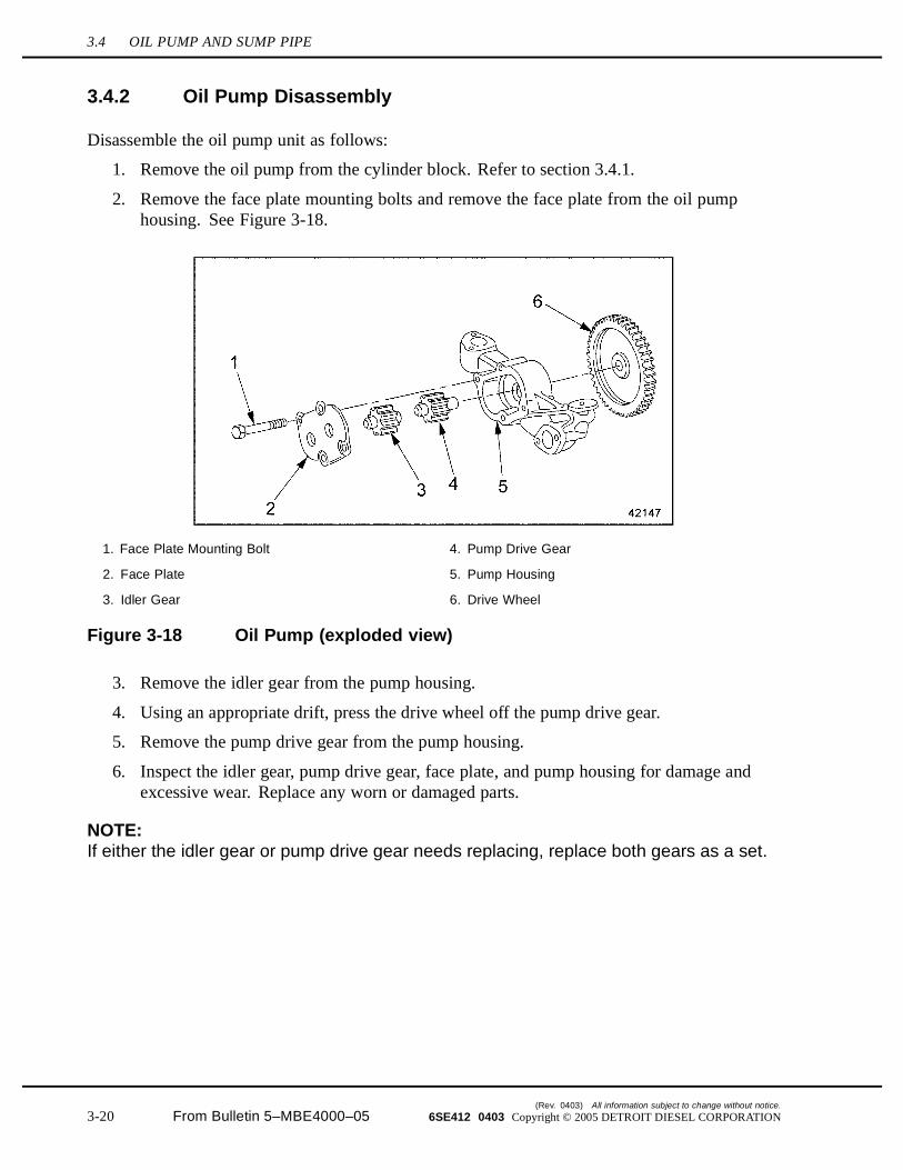
2. Remove the face plate mounting bolts and remove the face plate from the oil pumphousing. See Figure 3-18.
1. Face Plate Mounting Bolt 4. Pump Drive Gear
2. Face Plate 5. Pump Housing
3. Idler Gear 6. Drive Wheel
Figure 3-18 Oil Pump (exploded view)
3. Remove the idler gear from the pump housing.
4. Using an appropriate drift, press the drive wheel off the pump drive gear.
5. Remove the pump drive gear from the pump housing.
6. Inspect the idler gear, pump drive gear, face plate, and pump housing for damage andexcessive wear. Replace any worn or damaged parts.
NOTE:If either the idler gear or pump drive gear needs replacing, replace both gears as a set.
(Rev. 0403) All information subject to change without notice.
3-20 From Bulletin 5–MBE4000–05 6SE412 0403 Copyright © 2005 DETROIT DIESEL CORPORATION

MBE4000 SERVICE MANUAL
7. Check the idler and pump drive gears. Check their seats in the pump housing and faceplate. Listed in Table 3-1 are the acceptable limits.
Description mm (inch)
Diameter of Shaft Bore (in pump housing and face plate) 22.000-22.021 (0.8661-0.8670)
Diameter of Idler Gear and Pump Drive Gear Shaft 21.93-21.94 (0.8634-0.8638)
Clearance of Pump/Idler Gear to Walls of Pump Housing 0.030-0.122 (0.0012-0.0048)
Gear Backlash (clearance between gear cogs) 0.312-0.476 (0.0123-0.0187)
Table 3-1 Oil Pump Inspection Limits
[a] In the pump housing, measure the diameter of both gear shaft bores, the idler gearseat and the pump drive gear seat. If the measurements are not within acceptablelimits, replace the pump housing.
[b] Measure the diameter of both shaft bores in the face plate. If the measurements arenot within acceptable limits, replace the face plate.
[c] Measure the diameter of the pump drive gear shaft and the idler gear shaft. If themeasurements are not within acceptable limits, replace both gears as a set.
[d] Using a feeler gauge, measure the clearance between the gears and the pump housingwall. If the measurements are not within acceptable limits, replace both gears as a set.
[e] Using a feeler gauge, measure gear backlash (the clearance between two adjacentcogs on different gears). If the measurements are not within acceptable limits,replace both gears as a set.
3.4.3 Oil Pump Assembly
Assemble the oil pump unit as follows:
BURNS
To avoid injury from burning, use lifting tools andheat-resistant gloves when handling heated components.
1. Heat the drive wheel to approximately 80°C (176°F) in a hot water tank.
All information subject to change without notice. (Rev. 0403)
6SE412 0403 Copyright © 2005 DETROIT DIESEL CORPORATION From Bulletin 5–MBE4000–05 3-21
3.4 OIL PUMP AND SUMP PIPE
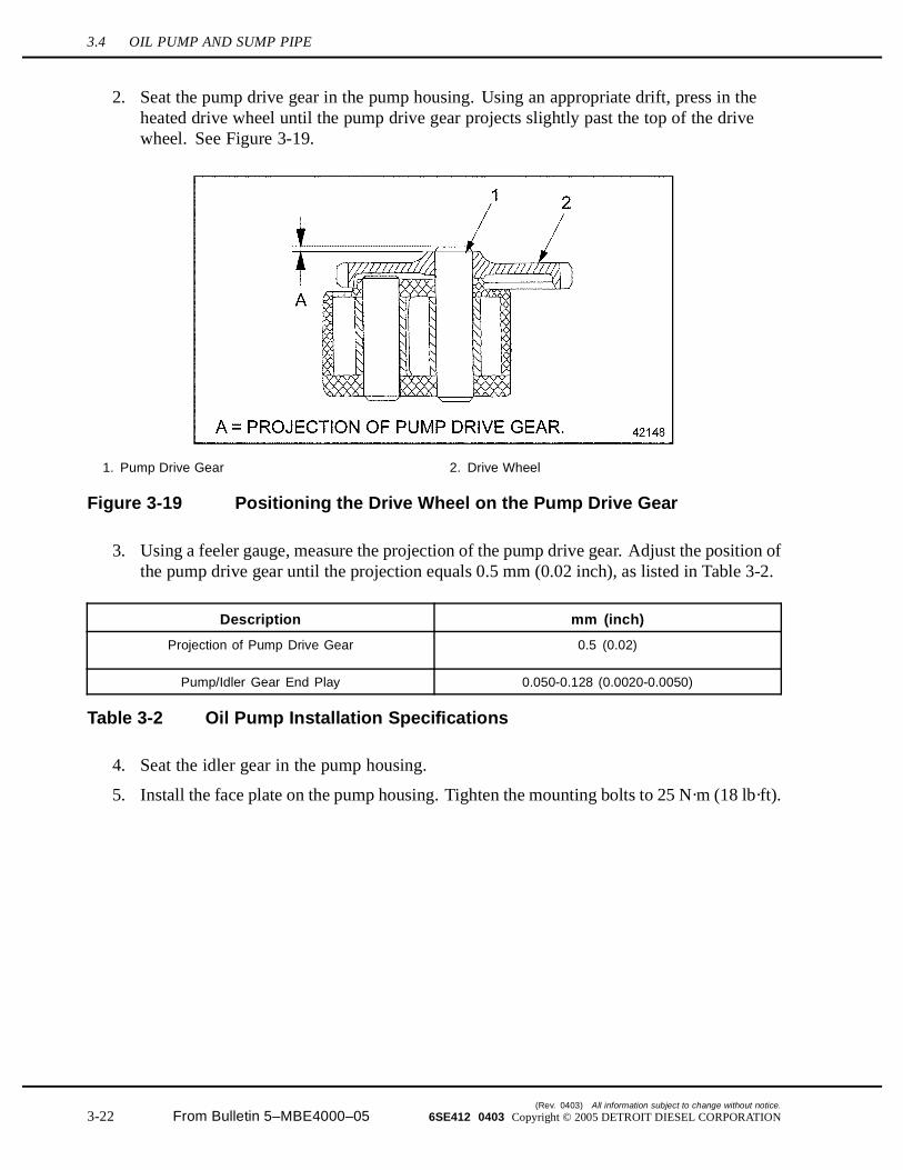
2. Seat the pump drive gear in the pump housing. Using an appropriate drift, press in theheated drive wheel until the pump drive gear projects slightly past the top of the drivewheel. See Figure 3-19.
1. Pump Drive Gear 2. Drive Wheel
Figure 3-19 Positioning the Drive Wheel on the Pump Drive Gear
3. Using a feeler gauge, measure the projection of the pump drive gear. Adjust the position ofthe pump drive gear until the projection equals 0.5 mm (0.02 inch), as listed in Table 3-2.
Description mm (inch)
Projection of Pump Drive Gear 0.5 (0.02)
Pump/Idler Gear End Play 0.050-0.128 (0.0020-0.0050)
Table 3-2 Oil Pump Installation Specifications
4. Seat the idler gear in the pump housing.
5. Install the face plate on the pump housing. Tighten the mounting bolts to 25 N·m (18 lb·ft).
(Rev. 0403) All information subject to change without notice.
3-22 From Bulletin 5–MBE4000–05 6SE412 0403 Copyright © 2005 DETROIT DIESEL CORPORATION

MBE4000 SERVICE MANUAL
6. Using a dial gauge, measure the end play of the pump drive gear and idler gear againstthe walls of the pump housing. See Figure 3-20 for set-up and listed in Table 3-2 arethe specifications.
1. Dial Gauge 3. Oil Pump
2. Support
Figure 3-20 Measuring the Clearance of the Pump Drive Gears
[a] Secure the assembled oil pump in a vise, with the face plate pointing up.
[b] Rest the dial gauge support on the face plate.
[c] Set up the dial gauge so that the feeler on the end of the gauge touches the exposedend of the pump drive gear with some preload.
[d] Force the pump drive gear downward as far as it will go.
[e] At this position, adjust the scale of the dial gauge to "0" (zero).
[f] Now force the pump drive gear upward as far as it will go. Read the measurement onthe dial gauge and make sure it conforms to the range listed in Table 3-2. Replacethe pump, if necessary.
[g] Repeat this procedure for the idler gear.
7. Install the oil pump in the cylinder block. Refer to section 3.4.4.
All information subject to change without notice. (Rev. 0403)
6SE412 0403 Copyright © 2005 DETROIT DIESEL CORPORATION From Bulletin 5–MBE4000–05 3-23

3.4 OIL PUMP AND SUMP PIPE
3.4.4 Oil Pump and Sump Pipe Installation
Install the oil pump and Sump Pipe as follows:
1. Coat the contact surface between the block and the oil pump with Loctite® 574.
2. Position the oil pump on the cylinder block. Make sure the teeth on the drive wheel of theoil pump mesh with the teeth of the crankshaft drive gear. Tighten the oil pump mountingbolt to 35 N·m (26 lb·ft). See Figure 3-21.
1. Valve Mounting Bolt 6. Sump Pipe Mounting Bolt
2. Pressure Limiting Valve 7. Sump Pipe
3. Oil Pump 8. Bracket
4. Oil Pump Mounting Bolt 9. Bracket Mounting Bolt
5. Gasket
Figure 3-21 Oil Pump and Sump Pipe Installation
NOTE:It may be necessary to rock the pump counterclockwise so the teeth of the drive wheelcan properly align with the crankshaft drive gear.
3. Check the backlash between the oil pump drive and the crankshaft gear. The specificationis 0.077 – 0.333 mm (0.003 – 0.131 in.).
4. Install the pressure limiting valve on the oil pump. Tighten the valve mounting bolt to35 N·m (26 lb·ft).
5. Install the sump pipe to the oil pump. Tighten all mounting bolts to 25 N·m (18 lb·ft).See Figure 3-21.
[a] Install the sump pipe bracket on the cylinder block.
[b] Install the sump pipe, with a new gasket, on the oil pump.
6. Install the oil pan with a new gasket. Refer to section 3.1.2.
(Rev. 0403) All information subject to change without notice.
3-24 From Bulletin 5–MBE4000–05 6SE412 0403 Copyright © 2005 DETROIT DIESEL CORPORATION

MBE4000 SERVICE MANUAL
7. Fill the engine oil circuit. The correct oil fill capacity is listed in Table 3-4.
PERSONAL INJURY
Diesel engine exhaust and some of its constituents areknown to the State of California to cause cancer, birthdefects, and other reproductive harm.□ Always start and operate an engine in a well ventilated
area.□ If operating an engine in an enclosed area, vent the
exhaust to the outside.□ Do not modify or tamper with the exhaust system or
emission control system.
8. Start the engine and check for leaks.
9. Check the engine oil level and add oil if necessary.
All information subject to change without notice. (Rev. 0403)
6SE412 0403 Copyright © 2005 DETROIT DIESEL CORPORATION From Bulletin 5–MBE4000–05 3-25

3.5 OIL FILTER
3.5 OIL FILTER
Perform the following procedures for removal and installation of the oil filter.
3.5.1 Oil Filter Element Replacement
Replace the oil filter element as follows:
1. Clean the outside of the oil filter housing, then unscrew the oil filter cap from the housing.See Figure 3-22.
Figure 3-22 Oil Filter Cap
NOTE:Use care to prevent foreign objects from entering the filter housing.
(Rev. 0403) All information subject to change without notice.
3-26 From Bulletin 5–MBE4000–05 6SE412 0403 Copyright © 2005 DETROIT DIESEL CORPORATION
MBE4000 SERVICE MANUAL
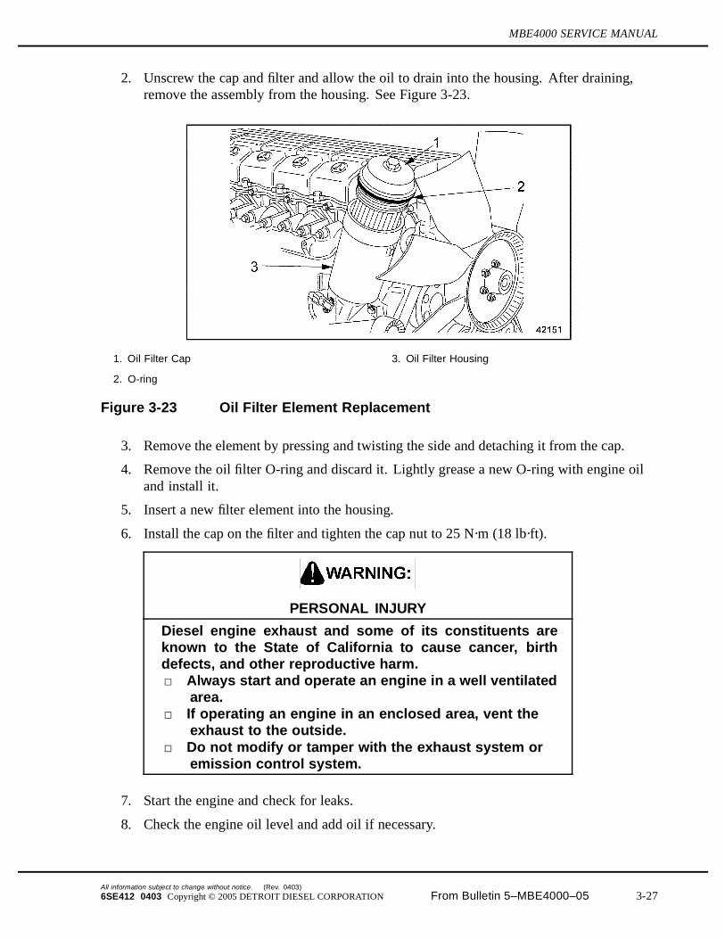
2. Unscrew the cap and filter and allow the oil to drain into the housing. After draining,remove the assembly from the housing. See Figure 3-23.
1. Oil Filter Cap 3. Oil Filter Housing
2. O-ring
Figure 3-23 Oil Filter Element Replacement
3. Remove the element by pressing and twisting the side and detaching it from the cap.
4. Remove the oil filter O-ring and discard it. Lightly grease a new O-ring with engine oiland install it.
5. Insert a new filter element into the housing.
6. Install the cap on the filter and tighten the cap nut to 25 N·m (18 lb·ft).
PERSONAL INJURY
Diesel engine exhaust and some of its constituents areknown to the State of California to cause cancer, birthdefects, and other reproductive harm.□ Always start and operate an engine in a well ventilated
area.□ If operating an engine in an enclosed area, vent the
exhaust to the outside.□ Do not modify or tamper with the exhaust system or
emission control system.
7. Start the engine and check for leaks.
8. Check the engine oil level and add oil if necessary.
All information subject to change without notice. (Rev. 0403)
6SE412 0403 Copyright © 2005 DETROIT DIESEL CORPORATION From Bulletin 5–MBE4000–05 3-27

3.6 OIL HEAT EXCHANGER/FILTER HOUSING
3.6 OIL HEAT EXCHANGER/FILTER HOUSING
Perform the following procedures for removal and installation of the oil heat exchanger/filterhousing.
3.6.1 Oil Heat Exchanger/Filter Housing Removal
Remove the oil heat exchanger/filter housing as follows:
HOT COOLANT
To avoid scalding from the expulsion of hot coolant, neverremove the cooling system pressure cap while the engineis at operating temperature. Wear adequate protectiveclothing (face shield, rubber gloves, apron, and boots).Remove the cap slowly to relieve pressure.
1. When the engine is cool, drain the coolant from the radiator.
2. Remove the turbocharger from the engine.
3. Disconnect the coolant pump shunt line from the coolant pump inlet pipe and move itout of the way.
4. Remove the oil filter cap. Inspect the O-ring and filter for damage and replace them ifnecessary. Drain the oil remaining in the filter into a clean container.
5. Disconnect the wiring harness from the oil pressure/temperature sensor.
(Rev. 0403) All information subject to change without notice.
3-28 From Bulletin 5–MBE4000–05 6SE412 0403 Copyright © 2005 DETROIT DIESEL CORPORATION
MBE4000 SERVICE MANUAL
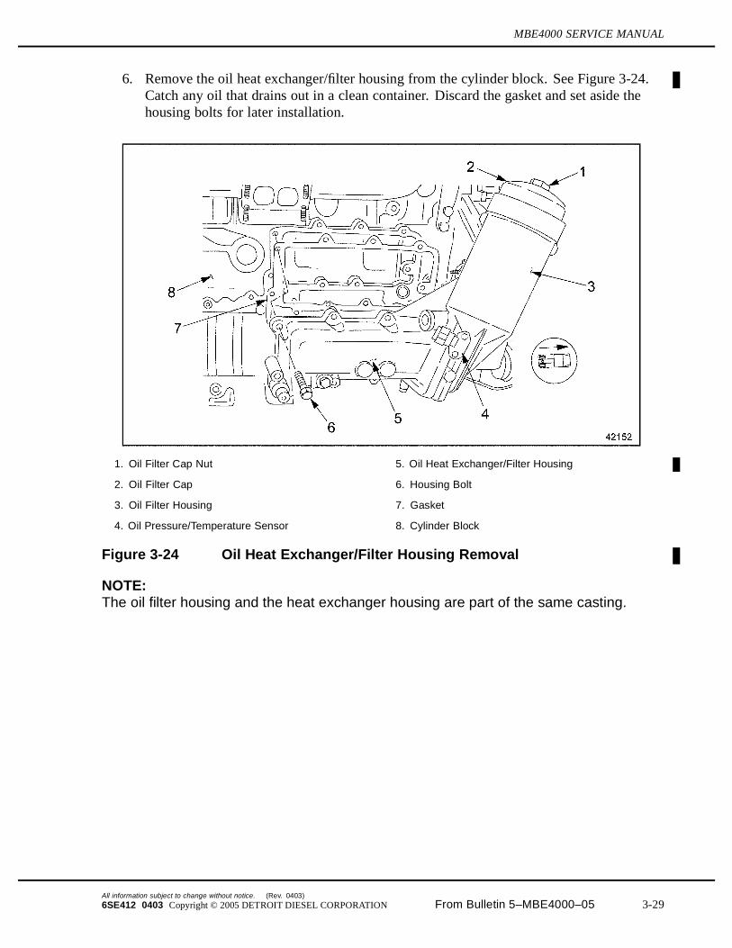
6. Remove the oil heat exchanger/filter housing from the cylinder block. See Figure 3-24.Catch any oil that drains out in a clean container. Discard the gasket and set aside thehousing bolts for later installation.
1. Oil Filter Cap Nut 5. Oil Heat Exchanger/Filter Housing
2. Oil Filter Cap 6. Housing Bolt
3. Oil Filter Housing 7. Gasket
4. Oil Pressure/Temperature Sensor 8. Cylinder Block
Figure 3-24 Oil Heat Exchanger/Filter Housing Removal
NOTE:The oil filter housing and the heat exchanger housing are part of the same casting.
All information subject to change without notice. (Rev. 0403)
6SE412 0403 Copyright © 2005 DETROIT DIESEL CORPORATION From Bulletin 5–MBE4000–05 3-29

3.6 OIL HEAT EXCHANGER/FILTER HOUSING
7. Remove the oil heat exchanger from the oil filter/heat exchanger housing. Discard thegaskets and save the heat exchanger bolts for later installation. See Figure 3-25.
1. Gasket 3. Oil Heat Exchanger Bolt
2. Oil Filter/Heat Exchanger Housing 4. Oil Heat Exchanger
Figure 3-25 Oil Heat Exchanger Assembly (typical)
8. Remove the oil pressure/temperature sensor from the oil heat exchanger/filter housing.Refer to section 3.7.1.
3.6.2 Oil Heat Exchanger/Filter Housing Installation
Install the oil heat exchanger/filter housing as follows:
1. Check the oil heat exchanger and the inside of the heat exchanger housing for corrosion,contamination by metal particles, or abrasive material, such as sand.
[a] If corrosion is found, clean or replace the oil heat exchanger, as necessary.
[b] Clean the mating surfaces of the oil heat exchanger and heat exchanger housing.Remove any bits of adhering gasket material.
2. Install the oil heat exchanger and new gaskets on the heat oil exchanger/filter housing.Tighten the heat exchanger bolts to 25 N·m (18 lb·ft).
(Rev. 0403) All information subject to change without notice.
3-30 From Bulletin 5–MBE4000–05 6SE412 0403 Copyright © 2005 DETROIT DIESEL CORPORATION

MBE4000 SERVICE MANUAL
3. Install the oil filter/heat exchanger housing on the cylinder block. Install the housingbolts and tighten them in the order shown in see Figure 3-26. Tighten each bolt to 60N·m (44 lb·ft).
Figure 3-26 Tightening Pattern, Heat Exchanger/Oil Filter Housing Bolts
[a] Clean the mating surfaces of the oil heat exchanger/filter housing and the cylinderblock. Remove any bits of adhering gasket material.
[b] Replace the oil heat exchanger/filter housing gasket.
4. Install a new filter element and O-ring in the oil filter housing. See Figure 3-27.
1. Oil Filter Cap 3. Oil Filter Element
2. O-ring
Figure 3-27 Oil Filter Assembly
5. Install the oil filter cap. Tighten the cap nut to 25 N·m (18 lb·ft).
All information subject to change without notice. (Rev. 0403)
6SE412 0403 Copyright © 2005 DETROIT DIESEL CORPORATION From Bulletin 5–MBE4000–05 3-31

3.6 OIL HEAT EXCHANGER/FILTER HOUSING
6. Install the oil pressure/temperature sensor on the oil heat exchanger/filter housing.Refer to section 3.7.2.
7. Connect the wiring harness to the oil pressure/temperature sensor.
8. Install the turbocharger on the engine. Refer to section 6.3.3.
9. Connect the coolant pump shunt line to the coolant pump inlet pipe.
10. Fill the cooling system. Refer to section 4.1.1.
PERSONAL INJURY
Diesel engine exhaust and some of its constituents areknown to the State of California to cause cancer, birthdefects, and other reproductive harm.□ Always start and operate an engine in a well ventilated
area.□ If operating an engine in an enclosed area, vent the
exhaust to the outside.□ Do not modify or tamper with the exhaust system or
emission control system.
11. Start the engine. Check the gauge for the correct oil pressure; check the oil lubricationsystem and the coolant pump inlet pipe for leaks. The correct oil pressures arelisted in Table 3-3.
Engine Speed Minimum Pressure
At idling rpm 50 kPa (7 psi)
At maximum rpm 250 kPa (36 psi)
Table 3-3 Engine Oil Pressures
(Rev. 0403) All information subject to change without notice.
3-32 From Bulletin 5–MBE4000–05 6SE412 0403 Copyright © 2005 DETROIT DIESEL CORPORATION
MBE4000 SERVICE MANUAL
3.7 OIL PRESSURE/TEMPERATURE SENSOR
The oil pressure/temperature sensor is located on the oil filter housing.
Perform the following procedures for removal and installation of the oil pressure/temperaturesensor.
3.7.1 Oil Pressure/Temperature Sensor Removal
Removal the oil pressure and temperature sensor as follows:
1. Loosen the oil filter cap. Lift up the cap and filter to allow the oil to drain. Inspect theO-ring for damage and replace if necessary.
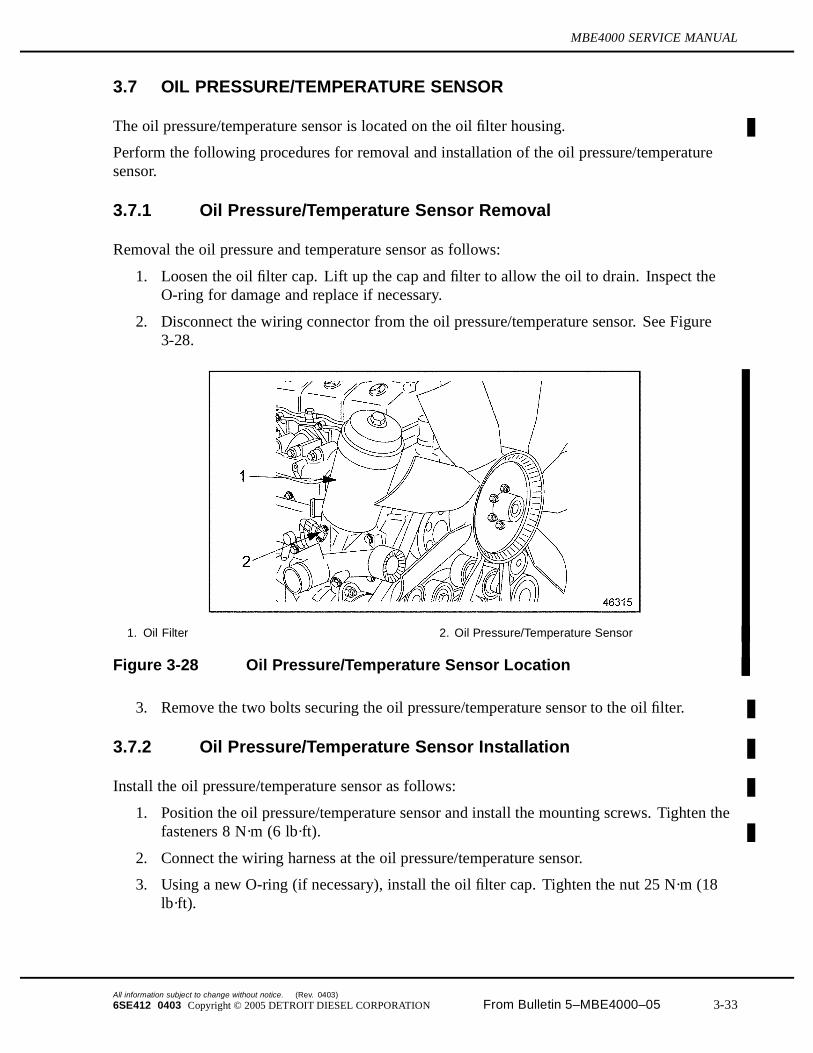
2. Disconnect the wiring connector from the oil pressure/temperature sensor. See Figure3-28.
1. Oil Filter 2. Oil Pressure/Temperature Sensor
Figure 3-28 Oil Pressure/Temperature Sensor Location
3. Remove the two bolts securing the oil pressure/temperature sensor to the oil filter.
3.7.2 Oil Pressure/Temperature Sensor Installation
Install the oil pressure/temperature sensor as follows:
1. Position the oil pressure/temperature sensor and install the mounting screws. Tighten thefasteners 8 N·m (6 lb·ft).
2. Connect the wiring harness at the oil pressure/temperature sensor.
3. Using a new O-ring (if necessary), install the oil filter cap. Tighten the nut 25 N·m (18lb·ft).
All information subject to change without notice. (Rev. 0403)
6SE412 0403 Copyright © 2005 DETROIT DIESEL CORPORATION From Bulletin 5–MBE4000–05 3-33

3.7 OIL PRESSURE/TEMPERATURE SENSOR
PERSONAL INJURY
Diesel engine exhaust and some of its constituents areknown to the State of California to cause cancer, birthdefects, and other reproductive harm.□ Always start and operate an engine in a well ventilated
area.□ If operating an engine in an enclosed area, vent the
exhaust to the outside.□ Do not modify or tamper with the exhaust system or
emission control system.
4. Start the engine. Check the gauge for the correct oil pressure listed in Table 3-9; andcheck the lubrication system for leaks. .
5. Check and add engine oil as needed.
(Rev. 0403) All information subject to change without notice.
3-34 From Bulletin 5–MBE4000–05 6SE412 0403 Copyright © 2005 DETROIT DIESEL CORPORATION

MBE4000 SERVICE MANUAL
3.A ADDITIONAL INFORMATION
Description Page
SPECIFICATIONS ............................................................................................. 3-36
Lubrication System ......................................................................................... 3-36
Oil Pump ......................................................................................................... 3-38
Oil Heat Exchanger ........................................................................................ 3-38
All information subject to change without notice. (Rev. 0403)
6SE412 0403 Copyright © 2005 DETROIT DIESEL CORPORATION From Bulletin 5–MBE4000–05 3-35
SPECIFICATIONS
This section contains the specifications for servicing the engine.
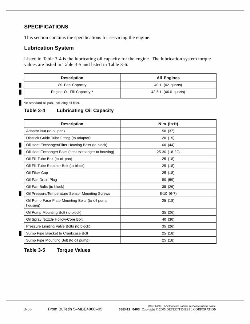
Lubrication System
Listed in Table 3-4 is the lubricating oil capacity for the engine. The lubrication system torquevalues are listed in Table 3-5 and listed in Table 3-6.
Description All Engines
Oil Pan Capacity 40 L (42 quarts)
Engine Oil Fill Capacity * 43.5 L (46.0 quarts)
*In standard oil pan, including oil filter.
Table 3-4 Lubricating Oil Capacity
Description N·m (lb·ft)
Adaptor Nut (to oil pan) 50 (37)
Dipstick Guide Tube Fitting (to adaptor) 20 (15)
Oil Heat Exchanger/Filter Housing Bolts (to block) 60 (44)
Oil Heat Exchanger Bolts (heat exchanger to housing) 25-30 (18-22)
Oil Fill Tube Bolt (to oil pan) 25 (18)
Oil Fill Tube Retainer Bolt (to block) 25 (18)
Oil Filter Cap 25 (18)
Oil Pan Drain Plug 80 (59)
Oil Pan Bolts (to block) 35 (26)
Oil Pressure/Temperature Sensor Mounting Screws 8-10 (6-7)
Oil Pump Face Plate Mounting Bolts (to oil pumphousing)
25 (18)
Oil Pump Mounting Bolt (to block) 35 (26)
Oil Spray Nozzle Hollow-Core Bolt 40 (30)
Pressure Limiting Valve Bolts (to block) 35 (26)
Sump Pipe Bracket to Crankcase Bolt 25 (18)
Sump Pipe Mounting Bolt (to oil pump) 25 (18)
Table 3-5 Torque Values
(Rev. 0403) All information subject to change without notice.
3-36 From Bulletin 5–MBE4000–05 6SE412 0403 Copyright © 2005 DETROIT DIESEL CORPORATION

MBE4000 SERVICE MANUAL
Description Torque, N·m (lb·ft)
Injector Unit Pump (IUP) Lubricator Bolt 20 (15)
Main Oil Gallery - Engine Block Rear bottomplug - M26 x 1.5
150 (110)
Main Oil Gallery - Inner Plug - M22 x 1.5 50 (37)
Main Oil Gallery - Engine Block Rear Top Plug - M24 x 1.5 120 (89)
Main Oil Gallery - Engine Block Front Plug - M22 X 1.5 100 (74)
Main Oil Gallery - Engine RIght Hand Side Top Plugbefore the Oil Filter Housing - M18 x 1.5
60 (44)
Main Oil Gallery - Engine Right Hand Side Bottom Plugbefore the Oil Filter Housing - M16 x 1.5
60 (44)
Main Oil Gallery - Engine Right Hand Side BottomPlug after the Oil Filter Housing - M16 x 1.5
60 (44)
Table 3-6 Torque Values
All information subject to change without notice. (Rev. 0403)
6SE412 0403 Copyright © 2005 DETROIT DIESEL CORPORATION From Bulletin 5–MBE4000–05 3-37

Oil Pump
The oil pump inspection limits are listed in Table 3-7. Listed in Table 3-8 are the oil pumpinstallation specifications.
Description mm (inch)
Diameter of Shaft Seat (in pump housing and face plate) 22.000-22.021 (0.8661-0.8670)
Diameter of Idler Gear and Pump Drive Gear Shaft 21.93-21.94 (0.8634-0.8638)
Clearance of Pump/Idler Gear to Walls of Pump Housing 0.030-0.122 (0.0012-0.0048)
Oil Pump Gear Backlash (clearance between gear cogs) 0.312-0.476 (0.0123-0.0187)
Table 3-7 Oil Pump Inspection Limits
Description mm (inch)
Projection of Pump Drive Gear 0.5 (0.02)
Pump/Idler Gear End Play 0.050-0.128 (0.0020-0.005)
Backlash of Oil Pump Drive Gear and Crankshaft Gear 0.077-0.333 (0.0030-0.1311)
Table 3-8 Oil Pump Installation Specifications
Oil Heat Exchanger
The minimum engine oil pressure is listed in Table 3-9.
Engine Speed Minimum Pressure
At idling rpm 50 kPa (7 psi)
At maximum rpm 250 kPa (36 psi)
Table 3-9 Engine Oil Pressures
(Rev. 0403) All information subject to change without notice.
3-38 From Bulletin 5–MBE4000–05 6SE412 0403 Copyright © 2005 DETROIT DIESEL CORPORATION


![[Tech-lubrication]Lubrication Inst for BEVT S1501CII ... · Microsoft Word - [Tech-lubrication]Lubrication Inst for BEVT S1501CII_20130613R02.doc Author: EHickman Created Date: 11/7/2013](https://static.fdocuments.net/doc/165x107/5f063c3e7e708231d416f958/tech-lubricationlubrication-inst-for-bevt-s1501cii-microsoft-word-tech-lubricationlubrication.jpg)