
3 Installation Touchpoint Plus Figure 6. 3.1 Mount the ...
2
1 Information Read this entire guide before installing the Touchpoint Plus, as it contains information that is essential for your safety and for the correct operation of the Touchpoint Plus. 1.1 Safety Incorrect setup, maintenance, operation or modification of the Touchpoint Plus gas detection system or its installation may constitute a serious hazard to the health and safety of personnel and their environment. It is therefore imperative that the contents of this chapter are thoroughly understood by everyone who has access to the gas and fire detection system or its associated equipment. 1.2 Conditions of Use This Touchpoint Plus equipment should only be operated under the following circumstances: • By properly trained personnel. • Under approved conditions. • With due authorisation. • Using approved maintenance and servicing procedures. 1.3 Packaging list Check that your package was undamaged, and that you have received the following: • Touchpoint Plus • Allen Key • Quick start guide (this document) Go to www.honeywellanalytics.com to download the Technical Handbook, which contains full install instructions. 2 General Introduction The Touchpoint Plus is an entry level (or upgrade) touch-screen digital controller for light industrial and commercial gas detection installations. It has eight inputs, with eight inputs available through an expansion unit. It can handle a wide range of milliamp, millivolt and catalytic sensors and analogue inputs, and it can control various outputs such as audible and visible signals and solenoid valves. The cabinets are constructed from high–impact plastic, are rated IP65, and have fully-sealed, easy opening access. They are supplied with a wall mount bracket or can be directly mounted to any solid vertical surface or rack. Cable entry is via entry glands on the lower side. Figure 1 shows the basic layout of the Touchpoint Plus Controller: Figure 1. Basic System Layout 3 Installation 3.1 Mount the Unit Directly to the Wall Figure 2. Wall Mounting Points 3.1.1 Fixings Required Screw x 4; corrosion resistant, sized according to the fixing surface: • Screw Head dia. < 14 mm (12.1 mm recommended) • Screw Body dia. < 7.5 mm (6.15 mm recommended) • Screw Length > 76.2 mm (3 in) (If using concrete anchor, > 55 mm + anchor depth) Flat Washer x 4; corrosion resistant, 19.05 mm max. OD, to fit the screws above. 3.2 Mount the Unit Using the Optional Wall Bracket Figure 3. Wall Mounting Options Refer to the wall mount bracket instructions (part number: TPPLOWMB). 4 Wiring and Connections 4.1 Power Connection The Touchpoint Plus systems are factory set to operate at a switchable voltage of 110/220 VAC, on a single phase, 50 to 60 Hz supply. They can also be wired to DC 18 — 32 V. Every Unit has a typical peak power consumption of less than 105W, and must be directly connected to supplies via a Main Isolator Switch that leaves protective earth (ground) permanently connected. The circuit should incorporate a Residual Current Device or Residual Current Circuit Breaker (RCD or RCCB). Touchpoint Plus systems are not certified for connection to domestic power supplies. 4.2 Expansion Power Module TPPL has the option to add an expansion unit that has the same power equipment and modules as the base unit except that it has no Motherboard or GUI. See Figure 5 for wiring details. 4.3 AC Power Supply To confirm or alter the pre-set operating voltage, open the system front cover, locate the SMPS RS–150–24 transformer and, if required, change the voltage selector inserting a screwdriver at the point shown by the Voltage Selector label below: Figure 4. Switched Mode Power Supply (SMPS) Connections Note: Mains Earth (Ground) must only be connected to the Protective Earth (Ground) rail, and not to the SMPS. Regional power cable wires are coloured in accordance with the following code: Wire Europe Canada USA Asia Protective Earth (Ground) Green + Yellow Green Green Green Isolated Earth (Ground) — Green Green + Yellow — Neutral Blue White White Black Live Brown Red or Black Blue, Red, or Black Red, Yellow, or Blue Table 1. Regional Power Cable Colours Before making any electrical connections or changes ensure: • The mains supply isolator switch and backup battery switch are in the Off position. • The system is set up to operate at the correct voltage. Refer to the User Manual for further information on system electrical specifications and power requirements. Note 1: Input voltage of less than 24 VDC will fail to charge the backup battery, and the battery will discharge over time. Note 2: Remote sensors may need their own power supplies if they exceed 15W power consumption. Figure 5. Mains Power Supplies 4.4 DC Power Supply It is possible to power the Touchpoint Plus controller directly from a DC 24V supply without using AC supplies at all. However, batteries alone will not suffice as they must not drop below 22 volts. Note: The system must still be connected to Protective Earth (Ground) when using an external DC supply. Figure 6. DC 24 V Input Terminals 4.5 Field Device Cables Field Device cabling (sensors, lights, solenoids, etc.) should be appropriate to the zone classification, and in accordance with the device manufacturer’s recommendations. Refer to local and national regulations where appropriate, and to the device user manual. All sensor field cables must be screened and earthed (grounded) in order to: • Ensure correct operation of the system • Avoid spurious signals • Meet European Standards for RFI and EMC. Ensure that the maximum loop resistance is not exceeded, as specified by the device manufacturer. Take account of voltage drops due to line resistance to ensure that the correct voltage level is present at the field device, as specified by the device manufacturer. The I/O modules will accept wire sizes to a maximum of 2.5 mm². 4.6 Main Module Connections The Main Module controls the Touchpoint Plus and its ancillary components. Terminal Label Channel Remarks 1 +DC Power +18 – 32 V 2 –DC -V Return 3 — Earth / Ground 4 NC System State Relay 1 Fig. 12 5 COM Fig. 12 6 NO Fig. 12 7 NC System State Relay 2 Fig. 12 8 COM Fig. 12 9 NO Fig. 12 10 NC System Failure Relay 3 Fig. 12 11 COM Fig. 12 12 NO Fig. 12 13 +24 VDC Visual Output Fig. 7 14 VIS Fig. 7 15 Unused — 16 A1 External Alarms Fig. 7 17 A2 Fig. 7 18 F Fig. 7 19 +24 VDC External Alarm Power Fig. 7 20 +24 VDC Fig. 7 21 +24 VDC Fig. 7 22 3.3 V Remote COM/Reset/Inhibit Fig. 13 23 R1 Fig. 13 24 R2 Fig. 13 25 CAN_H CAN Expansion Unit Connection 26 CAN_L Expansion Unit Connection Table 2. Main Module Connections 4.7 mA Input Module Connections This is an optional module for providing up to eight mA loop inputs. (see Technical Handbook, Ch.5.2.10) Terminal Label Input Field Device 1 +Ve mA input 1 + 24 VDC 2 –Ve 0 VDC Touchpoint Plus Quick Start Guide English Basic Unit Expansion Unit Isolator Switch
Transcript of 3 Installation Touchpoint Plus Figure 6. 3.1 Mount the ...
1 Information Read this entire guide before installing the Touchpoint Plus, as it contains information that is essential for your safety and for the correct operation of the Touchpoint Plus.
1.1 Safety Incorrect setup, maintenance, operation or modification of the Touchpoint Plus gas detection system or its installation may constitute a serious hazard to the health and safety of personnel and their environment. It is therefore imperative that the contents of this chapter are thoroughly understood by everyone who has access to the gas and fire detection system or its associated equipment.
1.2 Conditions of Use This Touchpoint Plus equipment should only be operated under the following circumstances:
• By properly trained personnel.
• Under approved conditions.
• With due authorisation.
• Using approved maintenance and servicing procedures.
1.3 Packaging list Check that your package was undamaged, and that you have received the following:
• Touchpoint Plus
• Allen Key
• Quick start guide (this document)
Go to www.honeywellanalytics.com to download the Technical Handbook, which contains full install instructions.
2 General Introduction The Touchpoint Plus is an entry level (or upgrade) touch-screen digital controller for light industrial and commercial gas detection installations.
It has eight inputs, with eight inputs available through an expansion unit.
It can handle a wide range of milliamp, millivolt and catalytic sensors and analogue inputs, and it can control various outputs such as audible and visible signals and solenoid valves.
The cabinets are constructed from high–impact plastic, are rated IP65, and have fully-sealed, easy opening access. They are supplied with a wall mount bracket or can be directly mounted to any solid vertical surface or rack. Cable entry is via entry glands on the lower side.
Figure 1 shows the basic layout of the Touchpoint Plus Controller:
Figure 1. Basic System Layout
3 Installation
3.1 Mount the Unit Directly to the Wall
Figure 2. Wall Mounting Points
3.1.1 Fixings Required Screw x 4; corrosion resistant, sized according to the fixing surface:
• Screw Head dia. < 14 mm (12.1 mm recommended)
• Screw Body dia. < 7.5 mm (6.15 mm recommended)
• Screw Length > 76.2 mm (3 in) (If using concrete anchor, > 55 mm + anchor depth)
Flat Washer x 4; corrosion resistant, 19.05 mm max. OD, to fit the
screws above.
3.2 Mount the Unit Using the Optional Wall Bracket
Figure 3. Wall Mounting Options
Refer to the wall mount bracket instructions (part number:
TPPLOWMB).
4 Wiring and Connections
4.1 Power Connection
The Touchpoint Plus systems are factory set to operate at a
switchable voltage of 110/220 VAC, on a single phase, 50 to 60 Hz
supply. They can also be wired to DC 18 — 32 V.
Every Unit has a typical peak power consumption of less than 105W,
and must be directly connected to supplies via a Main Isolator
Switch that leaves protective earth (ground) permanently
connected.
The circuit should incorporate a Residual Current Device or Residual
Current Circuit Breaker (RCD or RCCB).
Touchpoint Plus systems are not certified for connection to
domestic power supplies.
4.2 Expansion Power Module
TPPL has the option to add an expansion unit that has the same
power equipment and modules as the base unit except that it has no
Motherboard or GUI. See Figure 5 for wiring details.
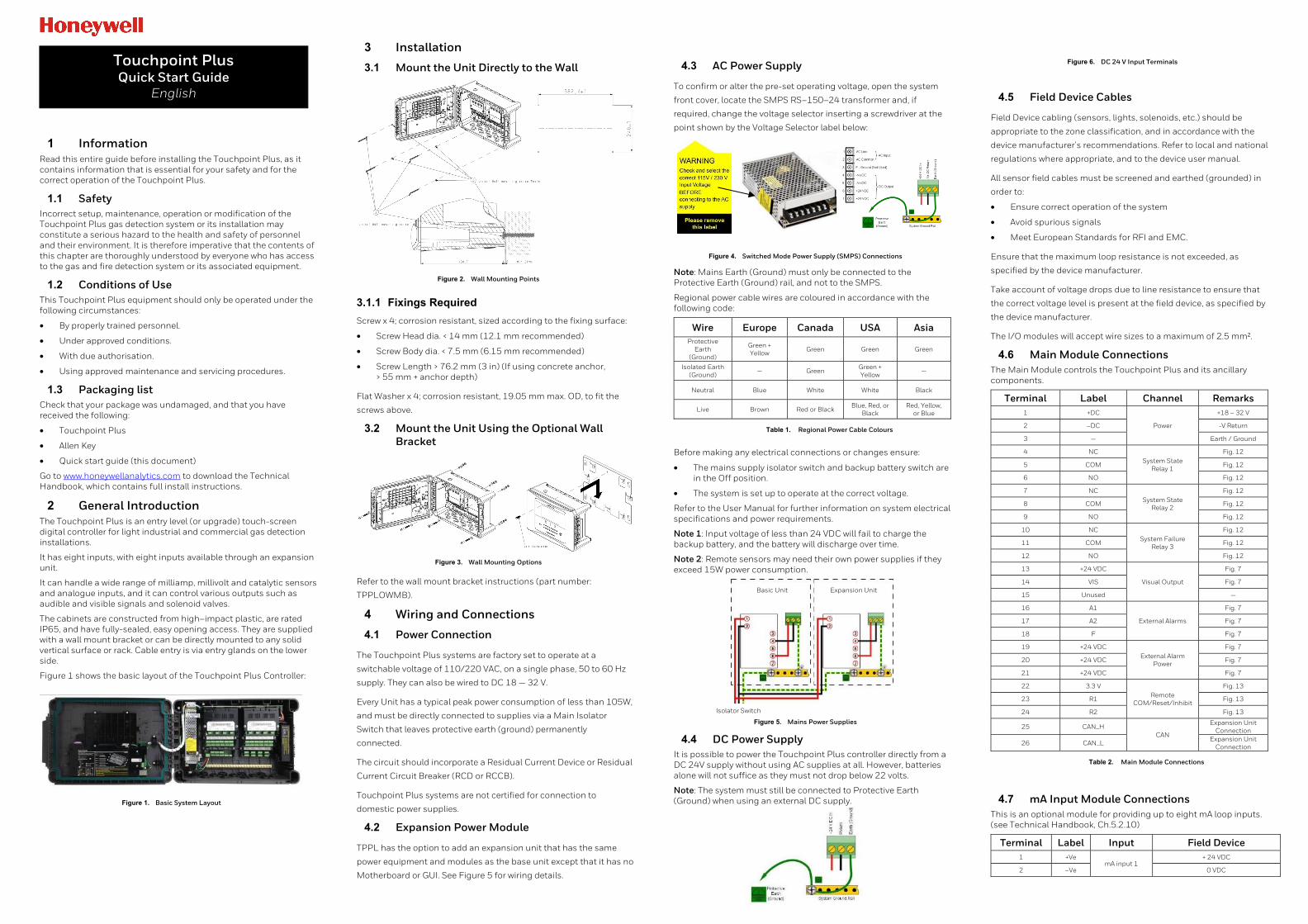
4.3 AC Power Supply
To confirm or alter the pre-set operating voltage, open the system
front cover, locate the SMPS RS–150–24 transformer and, if
required, change the voltage selector inserting a screwdriver at the
point shown by the Voltage Selector label below:
Figure 4. Switched Mode Power Supply (SMPS) Connections
Note: Mains Earth (Ground) must only be connected to the Protective Earth (Ground) rail, and not to the SMPS.
Regional power cable wires are coloured in accordance with the following code:
Wire Europe Canada USA Asia Protective
Earth (Ground)
Green + Yellow Green Green Green
Isolated Earth (Ground)
— Green Green + Yellow
—
Neutral Blue White White Black
Live Brown Red or Black Blue, Red, or
Black Red, Yellow,
or Blue
Table 1. Regional Power Cable Colours
Before making any electrical connections or changes ensure:
• The mains supply isolator switch and backup battery switch are in the Off position.
• The system is set up to operate at the correct voltage.
Refer to the User Manual for further information on system electrical specifications and power requirements.
Note 1: Input voltage of less than 24 VDC will fail to charge the backup battery, and the battery will discharge over time.
Note 2: Remote sensors may need their own power supplies if they exceed 15W power consumption.
Figure 5. Mains Power Supplies
4.4 DC Power Supply It is possible to power the Touchpoint Plus controller directly from a DC 24V supply without using AC supplies at all. However, batteries alone will not suffice as they must not drop below 22 volts.
Note: The system must still be connected to Protective Earth (Ground) when using an external DC supply.
Figure 6. DC 24 V Input Terminals
4.5 Field Device Cables
Field Device cabling (sensors, lights, solenoids, etc.) should be
appropriate to the zone classification, and in accordance with the
device manufacturer’s recommendations. Refer to local and national
regulations where appropriate, and to the device user manual.
All sensor field cables must be screened and earthed (grounded) in
order to:
• Ensure correct operation of the system
• Avoid spurious signals
• Meet European Standards for RFI and EMC.
Ensure that the maximum loop resistance is not exceeded, as
specified by the device manufacturer.
Take account of voltage drops due to line resistance to ensure that
the correct voltage level is present at the field device, as specified by
the device manufacturer.
The I/O modules will accept wire sizes to a maximum of 2.5 mm².
4.6 Main Module Connections The Main Module controls the Touchpoint Plus and its ancillary components.
Terminal Label Channel Remarks 1 +DC
Power
+18 – 32 V
2 –DC -V Return
3 — Earth / Ground
4 NC System State
Relay 1
Fig. 12
5 COM Fig. 12
6 NO Fig. 12
7 NC System State
Relay 2
Fig. 12
8 COM Fig. 12
9 NO Fig. 12
10 NC System Failure
Relay 3
Fig. 12
11 COM Fig. 12
12 NO Fig. 12
13 +24 VDC
Visual Output
Fig. 7
14 VIS Fig. 7
15 Unused —
16 A1
External Alarms
Fig. 7
17 A2 Fig. 7
18 F Fig. 7
19 +24 VDC External Alarm
Power
Fig. 7
20 +24 VDC Fig. 7
21 +24 VDC Fig. 7
22 3.3 V Remote
COM/Reset/Inhibit
Fig. 13
23 R1 Fig. 13
24 R2 Fig. 13
25 CAN_H CAN
Expansion Unit Connection
26 CAN_L Expansion Unit
Connection
Table 2. Main Module Connections
4.7 mA Input Module Connections This is an optional module for providing up to eight mA loop inputs. (see Technical Handbook, Ch.5.2.10)
Terminal Label Input Field Device 1 +Ve
mA input 1 + 24 VDC
2 –Ve 0 VDC
Touchpoint Plus Quick Start Guide
English
Basic Unit Expansion Unit
Isolator Switch
3 Sig 4 – 20 mA signal
4 +Ve
mA input 2
+ 24 VDC
5 –Ve 0 VDC
6 Sig 4 – 20 mA signal
7 +Ve
mA input 3
+ 24 VDC
8 –Ve 0 VDC
9 Sig 4 – 20 mA signal
10 +Ve
mA input 4
+ 24 VDC
11 –Ve 0 VDC
12 Sig 4 – 20 mA signal
13 +Ve
mA input 5
+ 24 VDC
14 –Ve 0 VDC
15 Sig 4 – 20 mA signal
16 +Ve
mA input 6
+ 24 VDC
17 –Ve 0 VDC
18 Sig 4 – 20 mA signal
19 +Ve
mA input 7
+ 24 VDC
20 –Ve 0 VDC
21 Sig 4 – 20 mA signal
22 +Ve
mA input 8
+ 24 VDC
23 –Ve 0 VDC
24 Sig 4 – 20 mA signal
Table 3. mA Input Module Connections
4.8 mV Input Module Connections This is an optional module for mV CAT sensor inputs. (see Technical Handbook, Ch.5.2.11)
Terminal Label Input Field Device 1 S
mV input 1
Sensitive (+)
2 01 Signal
3 NS Sensitive (–)
4 S
mV input 2
Sensitive (+)
5 01 Signal
6 NS Sensitive (–)
7 S
mV input 3
Sensitive (+)
8 01 Signal
9 NS Sensitive (–)
10 S
mV input 4
Sensitive (+)
11 01 Signal
12 NS Sensitive (–)
13 S
mV input 5
Sensitive (+)
14 01 Signal
15 NS Sensitive (–)
16 S
mV input 6
Sensitive (+)
17 01 Signal
18 NS Sensitive (–)
19 S
mV input 7
Sensitive (+)
20 01 Signal
21 NS Sensitive (–)
22 S
mV input 8
Sensitive (+)
23 01 Signal
24 NS Sensitive (–)
Table 4. mV Input Module Connections
4.9 Dual Input Module This is an optional module for providing 2 or 4 x mA Loop + 2 or 4 x mV CAT inputs.
Terminal Label Input Field Device 1, 7, 4, 10 +Ve
mA Inputs 1 – 4
+ 24 VDC
2, 5, 8, 11 –Ve 0 VDC
3, 6, 9, 12 Sig 4 – 20 mA signal
13, 16, 19, 22 S mV Inputs 1 – 4 Sensitive (+)
14, 17, 20, 23 01 Signal
15, 18, 21, 24 NS Sensitive (–)
Table 5. Relay Output Module Connections
4.10 Modbus RTU Option This is an option that uses Modbus RTU (RS-485) control protocols. Full details are given in the Touchpoint Plus Modbus Installation Guide.
4.11 Relay Output Module Connections This is an optional module providing 12 relay outputs. (see Technical Handbook, Ch.5.2.14)
Terminal Label Output 1 NC
Relay 1 2 COM
3 NO
4 NC
Relay 2 5 COM
6 NO
7 NC
Relay 3 8 COM
9 NO
10 NC
Relay 4 11 COM
12 NO
13 NC
Relay 5 14 COM
15 NO
16 NC
Relay 6 17 COM
18 NO
19 NC
Relay 7 20 COM
21 NO
22 NC
Relay 8 23 COM
24 NO
25 NC
Relay 9 26 COM
27 NO
28 NC
Relay 10 29 COM
30 NO
31 NC
Relay 11 32 COM
33 NO
34 NC
Relay 12 35 COM
36 NO
Table 6. Relay Output Module Connections
4.12 mA Output Module This is an optional module for providing isolation mA loop output (see Technical Handbook, Ch.5.2.13).
Terminal Label Output 1 I+
mA Out 1 2 I–
3 I+mA Out 2
4 I–
5 I+mA Out 3
6 I–
7 I+mA Out 4
8 I–
Table 7. mA Output Module Connections
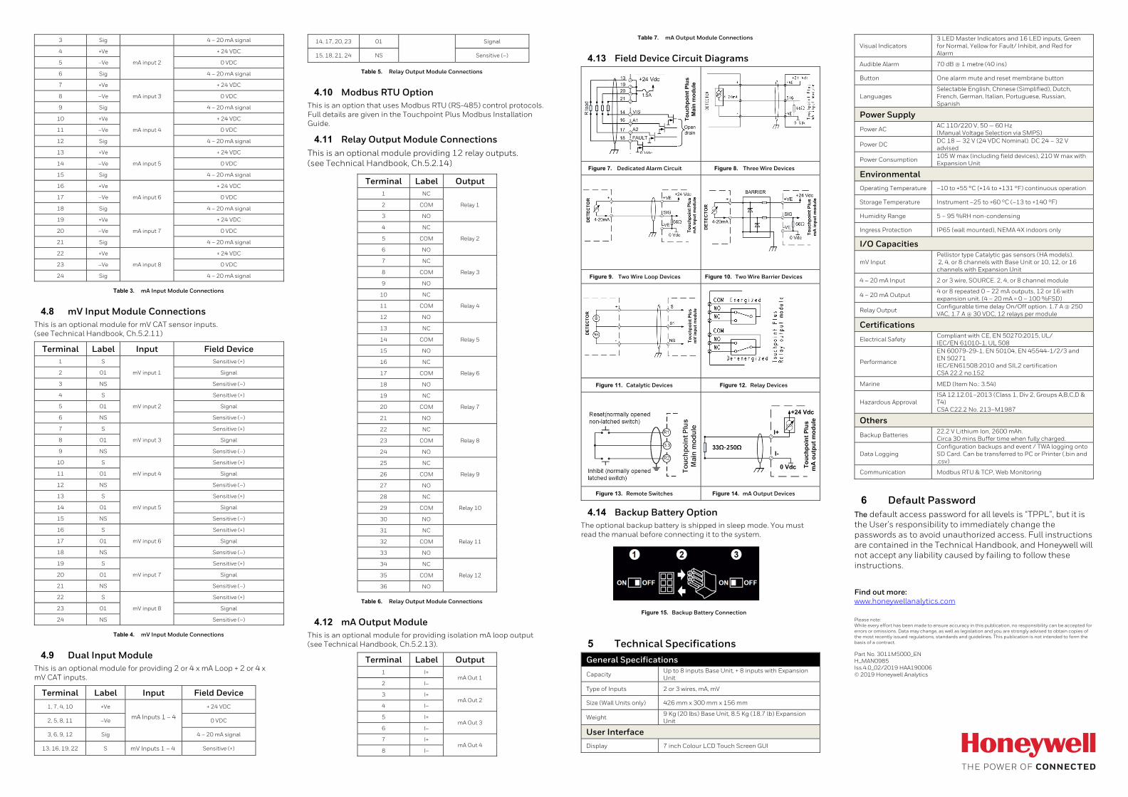
4.13 Field Device Circuit Diagrams
Figure 7. Dedicated Alarm Circuit Figure 8. Three Wire Devices
Figure 9. Two Wire Loop Devices Figure 10. Two Wire Barrier Devices
Figure 11. Catalytic Devices Figure 12. Relay Devices
Figure 13. Remote Switches Figure 14. mA Output Devices
4.14 Backup Battery Option The optional backup battery is shipped in sleep mode. You must read the manual before connecting it to the system.
Figure 15. Backup Battery Connection
5 Technical Specifications General Specifications
Capacity Up to 8 inputs Base Unit, + 8 inputs with Expansion Unit
Type of Inputs 2 or 3 wires, mA, mV
Size (Wall Units only) 426 mm x 300 mm x 156 mm
Weight 9 Kg (20 lbs) Base Unit, 8.5 Kg (18.7 lb) Expansion Unit
User InterfaceDisplay 7 inch Colour LCD Touch Screen GUI
Visual Indicators 3 LED Master Indicators and 16 LED inputs, Green for Normal, Yellow for Fault/ Inhibit, and Red for Alarm
Audible Alarm 70 dB @ 1 metre (40 ins)
Button One alarm mute and reset membrane button
Languages Selectable English, Chinese (Simplified), Dutch, French, German, Italian, Portuguese, Russian, Spanish
Power Supply
Power AC AC 110/220 V, 50 — 60 Hz (Manual Voltage Selection via SMPS)
Power DC DC 18 — 32 V (24 VDC Nominal). DC 24 – 32 V advised
Power Consumption 105 W max (including field devices), 210 W max with Expansion Unit
Environmental
Operating Temperature –10 to +55 °C (+14 to +131 °F) continuous operation
Storage Temperature Instrument –25 to +60 °C (–13 to +140 °F)
Humidity Range 5 – 95 %RH non-condensing
Ingress Protection IP65 (wall mounted), NEMA 4X indoors only
I/O Capacities
mV Input Pellistor type Catalytic gas sensors (HA models). 2, 4, or 8 channels with Base Unit or 10, 12, or 16 channels with Expansion Unit
4 – 20 mA Input 2 or 3 wire, SOURCE. 2, 4, or 8 channel module
4 – 20 mA Output 4 or 8 repeated 0 – 22 mA outputs, 12 or 16 with expansion unit. (4 – 20 mA = 0 – 100 %FSD)
Relay Output Configurable time delay On/Off option. 1.7 A @ 250 VAC, 1.7 A @ 30 VDC, 12 relays per module
Certifications
Electrical Safety Compliant with CE, EN 50270:2015, UL/ IEC/EN 61010-1, UL 508
Performance
EN 60079-29-1, EN 50104, EN 45544-1/2/3 and EN 50271 IEC/EN61508:2010 and SIL2 certification CSA 22.2 no.152
Marine MED (Item No.: 3.54)
Hazardous Approval ISA 12.12.01–2013 (Class 1, Div 2, Groups A,B,C,D & T4) CSA C22.2 No. 213–M1987
Others
Backup Batteries 22.2 V Lithium Ion, 2600 mAh. Circa 30 mins Buffer time when fully charged.
Data Logging Configuration backups and event / TWA logging onto SD Card. Can be transferred to PC or Printer (.bin and .csv)
Communication Modbus RTU & TCP, Web Monitoring
6 Default Password The default access password for all levels is “TPPL”, but it is the User’s responsibility to immediately change the passwords as to avoid unauthorized access. Full instructions are contained in the Technical Handbook, and Honeywell will not accept any liability caused by failing to follow these instructions.
Find out more: www.honeywellanalytics.com
Please note: While every effort has been made to ensure accuracy in this publication, no responsibility can be accepted for errors or omissions. Data may change, as well as legislation and you are strongly advised to obtain copies of the most recently issued regulations, standards and guidelines. This publication is not intended to form the basis of a contract.
Part No. 3011M5000_EN H_MAN0985 Iss.4.0_02/2019 HAA190006 © 2019 Honeywell Analytics