3-Easy ONE-PERSON OPERATION Steps 3 Store #7807 …
2
3-Easy Steps 3 Store 2 Lift Includes all mounting hardware 1 Secure Plan Location of 2-Point Lift System Read instructions before starting. Plan ceiling location of mounting board. Position welded screw eye (E) at top of adjoining wall. Distance from organizer (B) on end of board to welded screw eye must be equal or greater than lifting distance. See Fig. 2 and “Install Welded Screw Eye” instructions next page. Mount Board to Ceiling Draw a centerline the length of a 6' (1.83 m) 2" x 6" pine mounting board. Use a stud finder to locate ceiling trusses/rafters on which to mount system (follow manufacturer’s instructions). Drill four (three minimum) 5 / 16" (8 mm) evenly-spaced clearance holes on board centerline matching truss/rafter locations. Use holes in mounting board as template to mark ceiling. Drill truss/rafters using a 7 / 32" (5.5 mm) drill bit. Install board using 5 / 16" x 4" (8 x 100 mm) lag bolts (K) with flat washers (L). Do not over-tighten. Printed in USA 4977 04/15 Maximize garage space by storing items up and out of the way. This block-and-tackle system allows one person to easily raise and lower items with a single rope. A self- locking pulley grips instantly even if the rope is accidentally released. Tools/supplies needed (purchase separately): Electric/hand drill; drill bits: 3 /32" (2.5 mm), 7 /32" (6 mm); Stud finder; stepladder; safety glasses, tape measure; one (1) 2" x 6" x 6' (50 mm x 152 mm x 1.83 m) grade 2 or better pine board. #7807 maximum load: 60 lb (27 kg) SAVE TIME! READ THE ENTIRE MANUAL BEFORE BEGINNING HOISTER INSTALLATION. IMPORTANT SAFETY INFORMATION • DO NOT UNTIE ANY ROPES System comes ready to install. Leave F, G, and H together. • DO NOT RAISE OR LOWER HOISTER with anyone standing under object. • SECURELY ANCHOR each fastener to a truss/rafter. EASY TO USE EASY TO INSTALL COMPLETE KIT SELF-LOCKING STORE AT CEILING LEVEL One person can easily raise and lower with a single control rope. Three styles store everything from canoes, kayaks, and SUPs to bikes, ladders and roof racks. (45, 60, 90, 145, 200 lb) WE STORE IT ALL! ONE-PERSON OPERATION Raises and lowers easily with a single control rope. EASY TO INSTALL Kit comes complete. SAFE, SELF-LOCKING Safety cleat grips instantly if rope is accidentally released. LIFTS EVENLY From 10 to 200 lb. Web: www.hoister.com MAXIMIZE GARAGE SPACE WARNING: Do not screw into laminated rafters. They are not intended to accept fasteners. Consult rafter maker for recommendations. Screwing into laminated rafters can weaken system, causing load to fall which can cause an accident. WARNING: Do not over-tighten pigtail lag screws past top thread. This can weaken fastener hold which can weaken system, causing load to fall which can cause an accident. 225A Max Max Lifting weight Part No. Description Mechanical advantage ceiling height item width Min Max ft m ft m lb kg lb kg 7800 1-Point storage system bike/utility lift 2:1 10 3.05 — — 10 4.5 45 20 7801 4-Point storage system 3:1 10 3.05 5 1.52 15 7 60 27 7802 4-Point storage system 4:1 10 3.05 5 1.52 25 11 90 41 7803 4-Point storage system 6:1 10 3.05 5 1.52 45 20 145 66 7806 4-Point storage system 8:1 10 3.05 5 1.52 75 34 200 91 7807 2-Point storage system 3:1 10 3.05 5 1.52 15 7 60 27 7808 4-Point SUP storage system 2:1 10 3.05 5 1.52 10 4.5 45 20 WARNING! Strictly follow all instructions to avoid an accident, damage to property, personal injury, or death. See www.harken. com/manuals for additional safety information. WARNING! Do not use this product for human suspension. Components can fail causing person to fall, possibly resulting in serious injury or death. KIT INCLUDES A 2 Harken micro pulleys B 1 Harken organizer C 2 #10 x 2 1 /2" (6 x 63 mm) screws D 1 shackle E 1 welded screw eye F 1 Harken block and tackle G 2 black drop ropes: 1 long, 1 short H 1 single hoisting rope I 2 webbing straps with buckles 7' (2.13 m) J 2 pigtail lag screws K 4 lag bolts 5 /16" x 4" (8 x 100 mm) L 4 washers PURCHASE SEPARATELY IF NEEDED 1 pine board (riser) (grade 2) 2" x 6" x 7" (50 mm x 152 mm x 180 mm). Do not use for rafters running sideways. TOOLS Electric/hand drill Safety glasses Drill bits: 5 /32" (4 mm) 7 /32" (5.5 mm) 5 /16" (8 mm) Pencil Stud finder Stepladder Tape measure 224 Harken micro pulleys A 237 Harken organizer B HFS961 #10 x 2 1 /2" (6 mm x 63 mm) screws C HCP1452 28' drop ropes G 7754A.Assy Harken block and tackle F HCP1443 welded screw eye E 072 Harken shackle D HCP1483 35' single hoisting rope H HCP1660.SET webbing straps with buckles 7' (2.13 m) I HFS987 washers L HFS988 lag bolts 5 /16" x 4" (8 x 100 mm) K HCP1444 pigtail lag screws J Harken, Inc. • N15W24983 Bluemound Rd, Pewaukee, WI 53072-4974 • Tel: 262-691-3320 • Fax: 262-701-5780• Email: [email protected] • Web: www.hoister.com
Transcript of 3-Easy ONE-PERSON OPERATION Steps 3 Store #7807 …
3-EasySteps 3 Store
2 Lift
Includes all mounting
hardware
1 Secure
Plan Location of 2-Point Lift System Read instructions before starting. Plan ceiling location of mounting board. Position welded screw eye (E) at top of adjoining wall. Distance from organizer (B) on end of board to welded screw eye must be equal or greater than lifting distance. See Fig. 2 and “Install Welded Screw Eye” instructions next page.
Mount Board to Ceiling Draw a centerline the length of a 6' (1.83 m) 2" x 6" pine mounting board. Use a stud finder to locate ceiling trusses/rafters on which to mount system (follow manufacturer’s instructions). Drill four (three minimum) 5/16" (8 mm) evenly-spaced clearance holes on board centerline matching truss/rafter locations. Use holes in mounting board as template to mark ceiling. Drill truss/rafters using a 7/32" (5.5 mm) drill bit. Install board using 5/16" x 4" (8 x 100 mm) lag bolts (K) with flat washers (L). Do not over-tighten. Printed in USA 4977 04/15
Harken, Inc. • 1251 E. Wisconsin Ave. • Pewaukee, WI 53072 USA • Tel: 262-691-3320 • Fax: 262-691-3008 • Email: [email protected] • Web: www.hoister.com
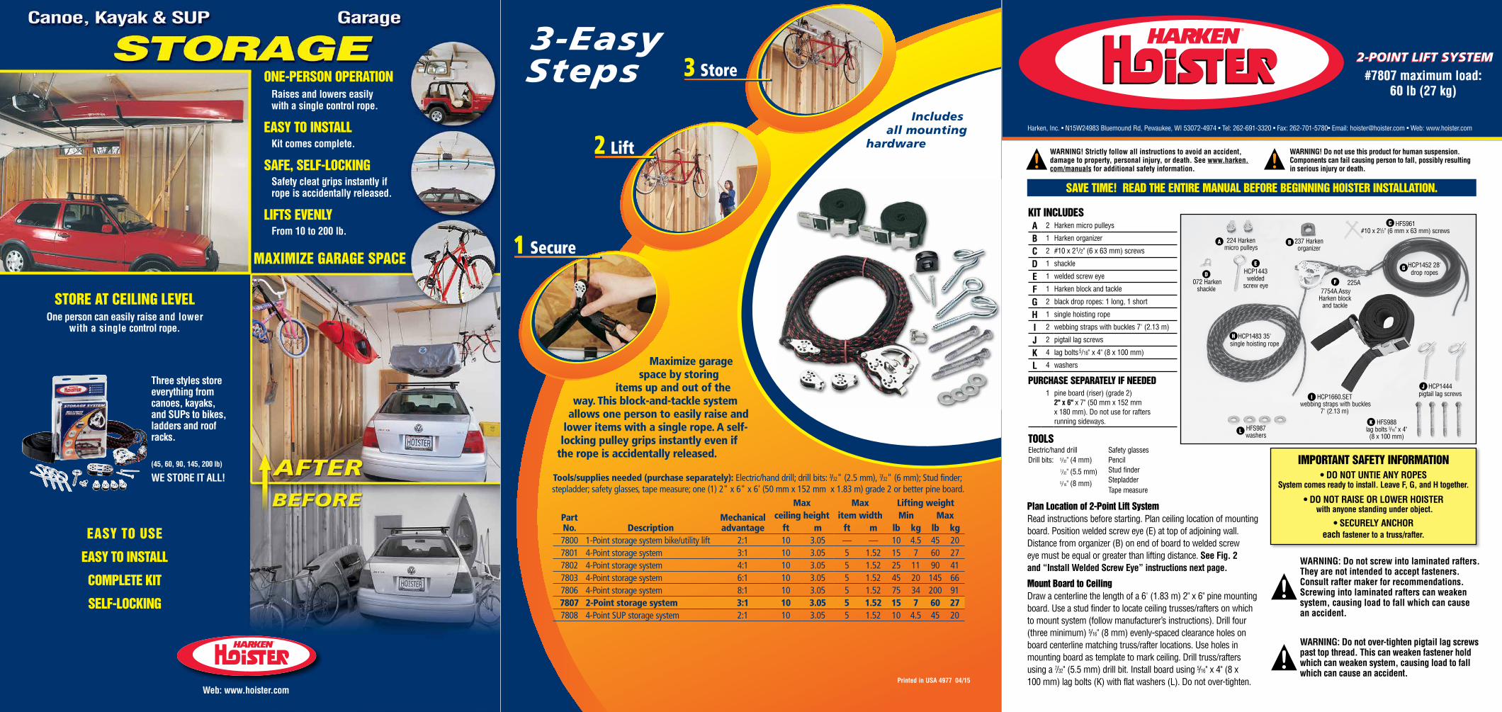
Maximize garage space by storing
items up and out of the way. This block-and-tackle system
allows one person to easily raise and lower items with a single rope. A self- locking pulley grips instantly even if
the rope is accidentally released.
Tools/supplies needed (purchase separately): Electric/hand drill; drill bits: 3/32" (2.5 mm), 7/32" (6 mm); Stud finder; stepladder; safety glasses, tape measure; one (1) 2" x 6" x 6' (50 mm x 152 mm x 1.83 m) grade 2 or better pine board.
#7807 maximum load:60 lb (27 kg)
SAVE TIME! READ THE ENTIRE MANUAL BEFORE BEGINNING HOISTER INSTALLATION.
IMPORTANT SAFETY INFORMATION• DO NOT UNTIE ANY ROPES
System comes ready to install. Leave F, G, and H together.
• DO NOT RAISE OR LOWER HOISTER with anyone standing under object.
• SECURELY ANCHOR each fastener to a truss/rafter.EASY TO USE
EASY TO INSTALL
COMPLETE KIT
SELF-LOCKING
STORE AT CEILING LEVELOne person can easily raise and lower
with a single control rope.
Three styles store everything from canoes, kayaks, and SUPs to bikes, ladders and roof racks.
(45, 60, 90, 145, 200 lb)
WE STORE IT ALL!
ONE-PERSON OPERATIONRaises and lowers easily with a single control rope.
EASY TO INSTALLKit comes complete.
SAFE, SELF-LOCKINGSafety cleat grips instantly if rope is accidentally released.
LIFTS EVENLYFrom 10 to 200 lb.
Web: www.hoister.com
MAXIMIZE GARAGE SPACE
WARNING: Do not screw into laminated rafters. They are not intended to accept fasteners. Consult rafter maker for recommendations. Screwing into laminated rafters can weaken system, causing load to fall which can cause an accident.
WARNING: Do not over-tighten pigtail lag screws past top thread. This can weaken fastener hold which can weaken system, causing load to fall which can cause an accident.
225A
Max Max Lifting weight
PartNo. Description
Mechanicaladvantage
ceiling height item width Min Maxft m ft m lb kg lb kg
7800 1-Point storage system bike/utility lift 2:1 10 3.05 — — 10 4.5 45 207801 4-Point storage system 3:1 10 3.05 5 1.52 15 7 60 277802 4-Point storage system 4:1 10 3.05 5 1.52 25 11 90 417803 4-Point storage system 6:1 10 3.05 5 1.52 45 20 145 667806 4-Point storage system 8:1 10 3.05 5 1.52 75 34 200 917807 2-Point storage system 3:1 10 3.05 5 1.52 15 7 60 277808 4-Point SUP storage system 2:1 10 3.05 5 1.52 10 4.5 45 20
WARNING! Strictly follow all instructions to avoid an accident, damage to property, personal injury, or death. See www.harken.com/manuals for additional safety information.
WARNING! Do not use this product for human suspension. Components can fail causing person to fall, possibly resulting in serious injury or death.
KIT INCLUDESA 2 Harken micro pulleys
B 1 Harken organizer
C 2 #10 x 21/2" (6 x 63 mm) screws
D 1 shackle
E 1 welded screw eye
F 1 Harken block and tackle
G 2 black drop ropes: 1 long, 1 short
H 1 single hoisting rope
I 2 webbing straps with buckles 7' (2.13 m)
J 2 pigtail lag screws
K 4 lag bolts 5/16" x 4" (8 x 100 mm)
L 4 washers
PURCHASE SEPARATELY IF NEEDED1 pine board (riser) (grade 2)
2" x 6" x 7" (50 mm x 152 mm x 180 mm). Do not use for rafters running sideways.
TOOLSElectric/hand drill Safety glassesDrill bits: 5/32" (4 mm)
7/32" (5.5 mm)5/16" (8 mm)
PencilStud finderStepladder Tape measure
224 Harken micro pulleys
A 237 Harken organizer
B
HFS961 #10 x 21/2" (6 mm x 63 mm) screws
C
HCP1452 28' drop ropes
G
7754A.Assy Harken block
and tackle
F
HCP1443 welded
screw eye
E
072 Harken shackle
D
HCP1483 35' single hoisting ropeH
HCP1660.SET webbing straps with buckles
7' (2.13 m)
I
HFS987 washers
LHFS988
lag bolts 5/16" x 4" (8 x 100 mm)
K
HCP1444 pigtail lag screws
J
Harken, Inc. • N15W24983 Bluemound Rd, Pewaukee, WI 53072-4974 • Tel: 262-691-3320 • Fax: 262-701-5780• Email: [email protected] • Web: www.hoister.com
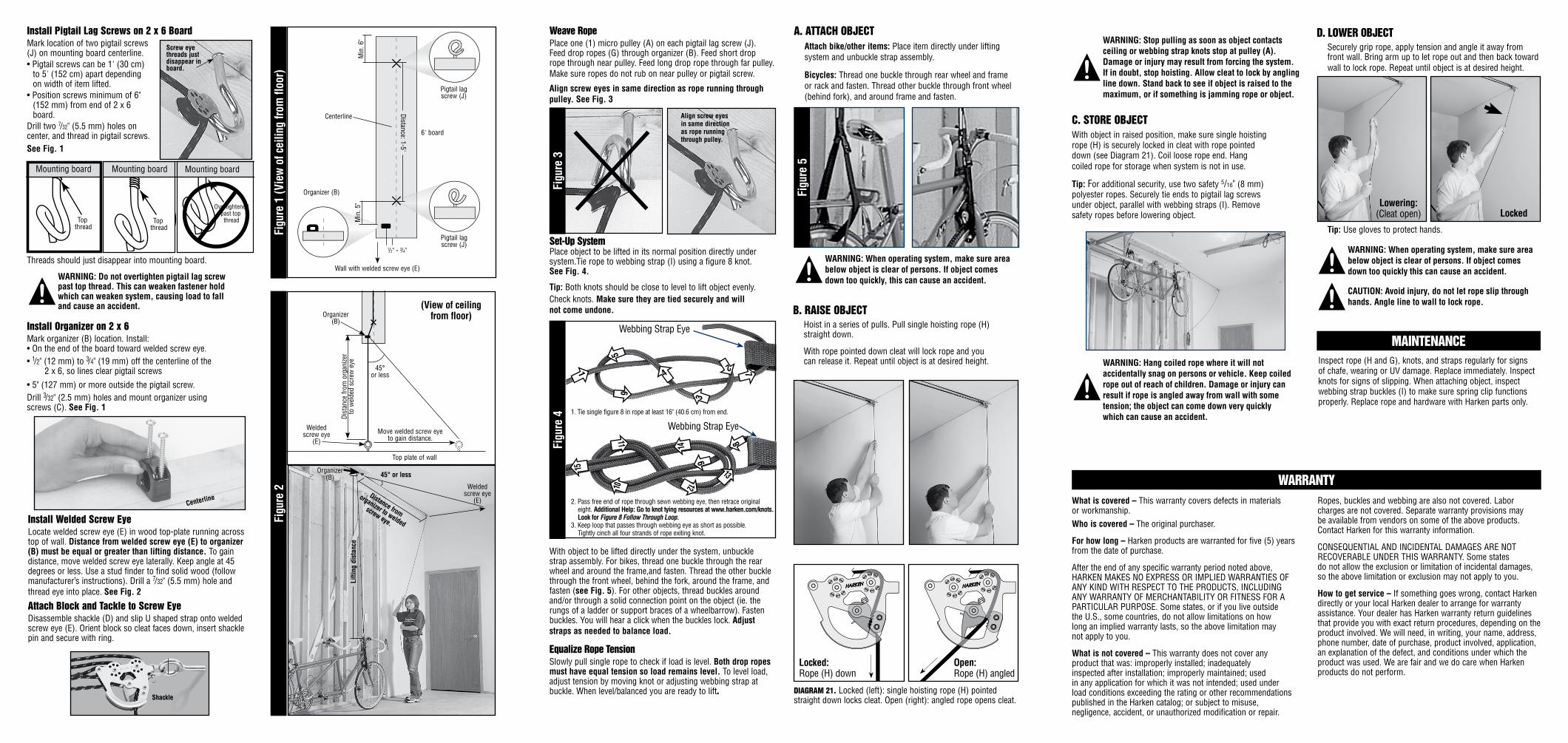
Install Welded Screw Eye Locate welded screw eye (E) in wood top-plate running across top of wall. Distance from welded screw eye (E) to organizer (B) must be equal or greater than lifting distance. To gain distance, move welded screw eye laterally. Keep angle at 45 degrees or less. Use a stud finder to find solid wood (follow manufacturer’s instructions). Drill a 7/32" (5.5 mm) hole and thread eye into place. See Fig. 2
Attach Block and Tackle to Screw Eye Disassemble shackle (D) and slip U shaped strap onto welded screw eye (E). Orient block so cleat faces down, insert shackle pin and secure with ring.
Install Organizer on 2 x 6 Mark organizer (B) location. Install: • On the end of the board toward welded screw eye.• 1/2" (12 mm) to 3/4" (19 mm) off the centerline of the 2 x 6, so lines clear pigtail screws
• 5" (127 mm) or more outside the pigtail screw.Drill 3/32" (2.5 mm) holes and mount organizer using screws (C). See Fig. 1
Install Pigtail Lag Screws on 2 x 6 Board Mark location of two pigtail screws (J) on mounting board centerline.• Pigtail screws can be 1' (30 cm) to 5' (152 cm) apart depending on width of item lifted.• Position screws minimum of 6" (152 mm) from end of 2 x 6 board.Drill two 7/32" (5.5 mm) holes on center, and thread in pigtail screws. See Fig. 1
Figu
re 2
Lifti
ng d
ista
nce
Screw eye threads just disappear in board.
Figu
re 1
(Vie
w o
f cei
ling
from
floo
r)
6' board
Centerline
Min
. 6"
Organizer (B)
Pigtail lag screw (J)
Pigtail lag screw (J)
Distance: 1-5'
1/2" - 3/4"
Min
. 5"
Wall with welded screw eye (E)
45° or less
Distance from
organizer to welded
screw eye.
Weave Rope Place one (1) micro pulley (A) on each pigtail lag screw (J). Feed drop ropes (G) through organizer (B). Feed short drop rope through near pulley. Feed long drop rope through far pulley. Make sure ropes do not rub on near pulley or pigtail screw.
Align screw eyes in same direction as rope running through pulley. See Fig. 3
Centerline
Top plate of wall
(View of ceiling from floor)
Welded screw eye
(E)
Organizer (B)
Dis
tanc
e fr
om o
rgan
izer
to
wel
ded
scre
w e
ye
Move welded screw eye to gain distance.
45° or less
Shackle
WARNING: When operating system, make sure area below object is clear of persons. If object comes down too quickly, this can cause an accident.
WARNING: Hang coiled rope where it will not accidentally snag on persons or vehicle. Keep coiled rope out of reach of children. Damage or injury can result if rope is angled away from wall with some tension; the object can come down very quickly which can cause an accident.
Top thread
Top thread
Mounting board Mounting board
Overtightenedpast top thread
Mounting board
Top thread
Top thread
Mounting board Mounting board
Overtightenedpast top thread
Mounting board
Top thread
Top thread
Mounting board Mounting board
Overtightenedpast top thread
Mounting board
Align screw eyes in same direction as rope running through pulley.
Figu
re 3
DIAGRAM 21. Locked (left): single hoisting rope (H) pointed straight down locks cleat. Open (right): angled rope opens cleat.
Locked: Rope (H) down
Open: Rope (H) angled
WARNING: Stop pulling as soon as object contacts ceiling or webbing strap knots stop at pulley (A). Damage or injury may result from forcing the system. If in doubt, stop hoisting. Allow cleat to lock by angling line down. Stand back to see if object is raised to the maximum, or if something is jamming rope or object.
B. RAISE OBJECTHoist in a series of pulls. Pull single hoisting rope (H) straight down.
With rope pointed down cleat will lock rope and you can release it. Repeat until object is at desired height.
WARNING: Do not overtighten pigtail lag screw past top thread. This can weaken fastener hold which can weaken system, causing load to fall and cause an accident.
C. STORE OBJECTWith object in raised position, make sure single hoisting rope (H) is securely locked in cleat with rope pointed down (see Diagram 21). Coil loose rope end. Hang coiled rope for storage when system is not in use.
Tip: For additional security, use two safety 5/16" (8 mm) polyester ropes. Securely tie ends to pigtail lag screws under object, parallel with webbing straps (I). Remove safety ropes before lowering object.
Tip: Use gloves to protect hands.
LockedLowering:
(Cleat open)
WARNING: When operating system, make sure area below object is clear of persons. If object comes down too quickly this can cause an accident.
CAUTION: Avoid injury, do not let rope slip through hands. Angle line to wall to lock rope.
Inspect rope (H and G), knots, and straps regularly for signs of chafe, wearing or UV damage. Replace immediately. Inspect knots for signs of slipping. When attaching object, inspect webbing strap buckles (I) to make sure spring clip functions properly. Replace rope and hardware with Harken parts only.
WARRANTY
MAINTENANCE
Threads should just disappear into mounting board.
1. Tie single figure 8 in rope at least 16" (40.6 cm) from end.
2. Pass free end of rope through sewn webbing eye, then retrace original eight. Additional Help: Go to knot tying resources at www.harken.com/knots. Look for Figure 8 Follow Through Loop.3. Keep loop that passes through webbing eye as short as possible. Tightly cinch all four strands of rope exiting knot.
Figu
re 4
1
2
3
4
5
6
7
Webbing Strap Eye
8
Webbing Strap Eye
9
10
11
12
13
14
15
With object to be lifted directly under the system, unbuckle strap assembly. For bikes, thread one buckle through the rear wheel and around the frame,and fasten. Thread the other buckle through the front wheel, behind the fork, around the frame, and fasten (see Fig. 5). For other objects, thread buckles around and/or through a solid connection point on the object (ie. the rungs of a ladder or support braces of a wheelbarrow). Fasten buckles. You will hear a click when the buckles lock. Adjust straps as needed to balance load.
Equalize Rope Tension Slowly pull single rope to check if load is level. Both drop ropes must have equal tension so load remains level. To level load, adjust tension by moving knot or adjusting webbing strap at buckle. When level/balanced you are ready to lift.
Set-Up System Place object to be lifted in its normal position directly under system.Tie rope to webbing strap (I) using a figure 8 knot. See Fig. 4.
Tip: Both knots should be close to level to lift object evenly.Check knots. Make sure they are tied securely and will not come undone.
Organizer (B)
Welded screw eye
(E)
A. ATTACH OBJECTAttach bike/other items: Place item directly under lifting system and unbuckle strap assembly.
Bicycles: Thread one buckle through rear wheel and frame or rack and fasten. Thread other buckle through front wheel (behind fork), and around frame and fasten.
D. LOWER OBJECTSecurely grip rope, apply tension and angle it away from front wall. Bring arm up to let rope out and then back toward wall to lock rope. Repeat until object is at desired height.
Figu
re 5
What is covered – This warranty covers defects in materials or workmanship.Who is covered – The original purchaser.
For how long – Harken products are warranted for five (5) years from the date of purchase.
After the end of any specific warranty period noted above, HARKEN MAKES NO EXPRESS OR IMPLIED WARRANTIES OF ANY KIND WITH RESPECT TO THE PRODUCTS, INCLUDING ANY WARRANTY OF MERCHANTABILITY OR FITNESS FOR A PARTICULAR PURPOSE. Some states, or if you live outside the U.S., some countries, do not allow limitations on how long an implied warranty lasts, so the above limitation may not apply to you.
What is not covered – This warranty does not cover any product that was: improperly installed; inadequately inspected after installation; improperly maintained; used in any application for which it was not intended; used under load conditions exceeding the rating or other recommendations published in the Harken catalog; or subject to misuse, negligence, accident, or unauthorized modification or repair.
Ropes, buckles and webbing are also not covered. Labor charges are not covered. Separate warranty provisions may be available from vendors on some of the above products. Contact Harken for this warranty information.
CONSEQUENTIAL AND INCIDENTAL DAMAGES ARE NOT RECOVERABLE UNDER THIS WARRANTY. Some states do not allow the exclusion or limitation of incidental damages, so the above limitation or exclusion may not apply to you.
How to get service – If something goes wrong, contact Harken directly or your local Harken dealer to arrange for warranty assistance. Your dealer has Harken warranty return guidelines that provide you with exact return procedures, depending on the product involved. We will need, in writing, your name, address, phone number, date of purchase, product involved, application, an explanation of the defect, and conditions under which the product was used. We are fair and we do care when Harken products do not perform.