3 Description of diagnostic letters F and E
58
ECODRIVE03 FGP-01VRS Description of diagnostic letters F... and E... 3-1 DOK-ECODR3-FGP-01VRS**-WAR1-EN-P 3 Description of diagnostic letters F... and E... 3.1 Error diagnostic messages F... Many areas are monitored in connection with operating modes and parameter settings. An error message is generated if a condition is discovered which no longer allows proper operation. The errors are separated into four different error classes. The error class is evident from the diagnostic message. They are determined with the drive's error response.. Error class : Diagnostic Message: Drive Reaction: Fatal F8xx Torque free switching Travel range F6xx Velocity command value-zero switch Interface F4xx In accordance with best possible deceleration Non-fatal F2xx In accordance with best possible deceleration Fig. 3-1: Error Classes and Drive Reaction If an error state is detected in the drive then an automatic operation of the drive's error response will be started as long the drive is in control. The H1 display blinks a Fx / xx. The drive's reaction can be parameterized by P-0-0119, Deceleration as best as possible, with interface and non-fatal errors. At the end of each error reaction the drive is switched off. Errors will not be automatically deleted but must be: • Reset from the control through the initialization of the command S-0-0099, Reset Class 1 Diagnostics, or • reset by pressing the "S1" button. If the error state is still present then the error will be immediately detected again. A positive edge bit on the control enable signal is necessary in order to turn on the drive again. Error Classes Drive's Error Reaction Reset the Error
Transcript of 3 Description of diagnostic letters F and E

ECODRIVE03 FGP-01VRS Description of diagnostic letters F... and E... 3-1
DOK-ECODR3-FGP-01VRS**-WAR1-EN-P
3 Description of diagnostic letters F... and E...
3.1 Error diagnostic messages F...
Many areas are monitored in connection with operating modes andparameter settings. An error message is generated if a condition isdiscovered which no longer allows proper operation.
The errors are separated into four different error classes. The error classis evident from the diagnostic message. They are determined with thedrive's error response..
Error class : Diagnostic
Message:
Drive Reaction:
Fatal F8xx Torque free switching
Travel range F6xx Velocity command value-zeroswitch
Interface F4xx In accordance with bestpossible deceleration
Non-fatal F2xx In accordance with bestpossible deceleration
Fig. 3-1: Error Classes and Drive Reaction
If an error state is detected in the drive then an automatic operation ofthe drive's error response will be started as long the drive is in control.The H1 display blinks a Fx / xx.
The drive's reaction can be parameterized by P-0-0119, Deceleration as
best as possible, with interface and non-fatal errors. At the end of eacherror reaction the drive is switched off.
Errors will not be automatically deleted but must be:
• Reset from the control through the initialization of the command
S-0-0099, Reset Class 1 Diagnostics, or
• reset by pressing the "S1" button.
If the error state is still present then the error will be immediately detectedagain.
A positive edge bit on the control enable signal is necessary in order toturn on the drive again.
Error Classes
Drive's Error Reaction
Reset the Error

3-2 Description of diagnostic letters F... and E... ECODRIVE03 FGP-01VRS
DOK-ECODR3-FGP-01VRS**-WAR1-EN-P
F207 Switching to uninitialized operation mode
Cause:
0 has been selected in at least one of the four mode parameters S-0-
0032..35. This mode has been selected by the bits 8 and 9 in the mastercontrol word while the drive controller was on.
Remedy:
Enter the desired mode in the activated mode parameter.
Examples for possible modes are:
Meaning:
Bit list of the mode
parameters:
Torque control 0000 0000 0000 0001
Velocity control 0000 0000 0000 0010
Position control with act. feedback val. 1 0000 0000 0000 x011
Position control with act. feedback val. 2 0000 0000 0000 x100
Drive-internal interpolation with actualfeedback value 1
0000 0000 0001 x011
Drive-internal interpolation with actualfeedback value 2
0000 0000 0001 x100
Relative drive-internal interpolation withactual feedback value 1
0000 0010 0001 x011
Relative drive-internal interpolation withactual feedback value 2
0000 0010 0001 x100
Fig. 3-4: Operation Modes
Which operation modes can be selected in a certain device is written inthe description for the operation mode parameters:
Parameter: Primary mode of operation S-0-0032
Secondary operation mode 1 S-0-0033
Secondary operation mode 2 S-0-0034
Secondary operation mode 3 S-0-0035
Check for input of the permissible interpolation method.
F208 UL The motor type has changed.
This indication happens when you power up for the first time with a newmotor.
The regulator settings for the current, velocity and position loops arestored in the feedback on the motor. After powering up, the drivecompares the motor type stored in the parameter with the connectedmotor type. If the two do not match, basic control loop settings must beadapted, too.
With the Basic Load command, the default control loop settings areloaded from the feedback memory into the drive. The previous loopsettings are overwritten. By pressing the S1 key, the command BasicLoad is started.
Causes:
• The motor has been exchanged.

ECODRIVE03 FGP-01VRS Description of diagnostic letters F... and E... 3-3
DOK-ECODR3-FGP-01VRS**-WAR1-EN-P
• A parameter file has been loaded, but the parameter P-0-4036,
Contacted motor type contained a motor type different from thepresent one.
Remedy:
Command C700 Basic load or press the S1 button.
F209 PL Load parameter default values
After replacing the firmware version, the drive displays “PL”, if theparameters have been changed in regards to the old product. Bypressing the S1 button on the drive controller or by starting the command“load basic parameters”, all the parameters will be erased and restoredwith the default (initial) values.
Cause:
The firmware has been exchanged; the number of parameters incomparison to the old product has changed.
Remedy:
Press S1 button on the drive controller, and all the parameters will beerased and restored with the factory preset default values
WARNING
⇒ This overwrites all parameters and positioning blocks.
F218 Amplifier overtemp. shutdown
The temperature of the amplifier’s heatsink is monitored. If the heatsinkis too hot, the drive will power down in order to protect against damage.
Cause:
1. Ambient temperature too high. The specified performance dataare valid up to an ambient temperature of 45°C.
2. The amplifier’s heatsink is dirty.
3. Air flow is prevented by other assembly parts or the controlcabinet assembly.
4. Blower defective
Remedy:
For 1. Reduce the ambient temperature, e.g. through cooling of thecontrol cabinet.
For 2. Remove obstructions or dirt from the heatsink.
For 3. Install the device vertically and clear a large enough area forproper heatsink ventilation.
For 4. Exchange drive.
F219 Motor overtemp. shutdown
The motor temperature has risen to an unacceptable level.
As soon as the temperature error threshold of 155°C is exceeded, thedrive will immediately be brought to a standstill as set in the error reaction(P-0-0119, best possible standstill).
3-4 Description of diagnostic letters F... and E... ECODRIVE03 FGP-01VRS
DOK-ECODR3-FGP-01VRS**-WAR1-EN-P
It applies:
temperature warning threshold < temperature error threshold
See also E251 Motor overtemperature warning.
Cause:
1. The motor is overloaded. The effective torque demanded from themotor has been above its allowable continuous torque level for toolong.
2. Wire break, ground short or short circuit in the motor temperaturemonitor line
3. Instability in the velocity loop
Remedy:
For 1. Check the installation of the motor. If the system has been inoperation for a long time, check to see if the the operatingconditions have changed. (in regards to pollution, friction, movedcomponents, etc.)
For 2. Check wires and cables to the motor temperature monitor for wirebreaks, earth short and short circuits.
For 3. Check velocity loop parameters.
F220 Bleeder overload shutdown
The regenerated energy from the mechanism of the machine via themotor has exceeded the capability of the braking resistor (bleeder). Byexceeding the maximum energy of the resistor, the drive will shutdownaccording to the set error reaction, thereby protecting the bleeder fromtemperature damage.
Cause:
The reflected energy from the machine’s mechanism over the motor istoo great.
Remedy:
With too much power reduce the acceleration value.
With too much energy reduce the velocity.
Check the drive installation.
May require installation of an additional bleeder module.
F221 Motor temp. surveillance defective
Cause:
Wire break or interruption in the wires for the motor temperaturemonitoring.
Remedy:
Check the wiring for the motor temperature monitoring (signalsMT(emp)+ and MT(emp)-) for interruption and short circuit.

ECODRIVE03 FGP-01VRS Description of diagnostic letters F... and E... 3-5
DOK-ECODR3-FGP-01VRS**-WAR1-EN-P
F226 Undervoltage in power section
The level of the DC bus voltage is monitored by the drive controller. If theDC bus voltage falls below a minimal threshold, the drive independentlyshuts down according to the set error reaction.
Cause:
1. The power source has been interrupted without first switching offthe drive enable (RF).
2. Disturbance in the power supply
Remedy:
For 1. Check the logic regarding the activation of the drive within theconnected control.
For 2. Check the power supply.
The error can be cleared by removing the drive enable signal.
F228 Excessive deviation
When the position loop is closed, the drive monitors whether it is able tofollow the specified command value. This is done by calculating a modelposition value in the drive and comparing that value with the actualfeedback value. If the difference between theoretical and actual position
value permanently exceeds the value of the S-0-0159, Monitoring
window parameter, the drive oviously cannot follow the given commandvalue. Then this error is generated.
Cause:
1. The drive's acceleration capacity has been exceeded.
2. The axis is blocked.
3. Incorrect parameter values set in the drive parameters.
4. Incorrect parameter values in S-0-0159, Monitoring window.
Remedy:
Ref. 1. Check the S-0-0092, Bipolar torque/force limit value parameterand set it to the maximum permissible value of the application.Reduce the specified acceleration value from the controller (seecontroller Manual).
Ref. 2. Check the mechanical system and eliminate jamming of the axis.
Ref. 3. Check the drive parameters (control loop tuning).
Ref. 4. Set the parameter values of S-0-0159, Monitoring window.
F229 Encoder 1 failure: quadrant error
With wrong signals in the encoder evaluation, a hardware error has beendiscovered in the encoder interface 1 being used.
Cause:
1. Defective encoder cable
2. Disruptive electro-magnetic interference on the encoder cable
3. Defective encoder interface
4. Defective drive controller

3-6 Description of diagnostic letters F... and E... ECODRIVE03 FGP-01VRS
DOK-ECODR3-FGP-01VRS**-WAR1-EN-P
Remedy:
For 1. Exchange the encoder cable.
For 2. Keep the encoder cable well away from the power cables.
For 3. Exchange the encoder interface.
For 4. Exchange the drive controller.
F230 Max. signal frequency of encoder 1 exceeded
The signal frequency of the encoder 1 (motor encoder) is checkedwhether the allowed max. frequency of the encoder interface isexceeded.
If the frequency is higher than allowed, the error F230, Max. signal
frequency of encoder 1 exceeded is generated. The position status ofthe encoder 1 is cleared to 0.
F234 Emergency-Stop
Cause:
The emergency stop function was activated by turning off the +24Vcurrent at the E-Stop input. The drive was brought to a standstill by thepreviously set error response.
Remedy:
1. Eliminate the condition which caused the +24V current at the E-Stop input to be turned off.
2. Do the "Reset class 1 diagnostic" command, e.g. with the controlsystem or the S1 button on the drive controller.
F236 Excessive position feedback difference
Cause:
In the communication phase 4 transition check command, positionfeedback value 1 and position feedback value 2 are set to the samevalue, and the cyclic evaluation of both encoders is started. In cyclicoperation (phase 4), the position feedback difference of both encoders is
compared with S-0-0391, Monitoring window feedback 2. If theamount of the difference exceeds the monitoring window, the error F236Excessive position feedback difference is diagnosed, the parameter-selected error response is performed, and the reference bits of bothencoders are cleared.
The monitoring is off, when the parameter S-0-0391, Monitoring windowfeedback 2 is set to the value 0.
Possible Causes :
1. Incorrect parameter for the encoder 2
(S-0-0115, Position feedback 2 type parameter,
S-0-0117, Resolution of feedback 2)
2. Incorrect parameter setting of mechanical system between motorshaft and encoder 2: (S-0-0121, Input revolutions of load gear,S-0-0122, Output revolutions of load gear,S-0-0123, Feed constant)
3. The mechanical system between motor shaft and encoder 2 is notrigid (e.g. gear play).
4. Defective encoder cable

ECODRIVE03 FGP-01VRS Description of diagnostic letters F... and E... 3-7
DOK-ECODR3-FGP-01VRS**-WAR1-EN-P
5. Maximum input frequency of the encoder interface exceeded
6. Encoder 2 (optional) is not mounted to the driven axis.
7. Incorrect reference measure of an absolute encoder
Remedy:
Ref. 1. Check S-0-0115, Position feedback 2 type parameter and
S-0-0117, Resolution of feedback 2.
Ref. 2. Check S-0-0121, S-0-0122, Input/Output revolutions of load
gear and S-0-0123, Feed constant.
Ref. 3. Increase S-0-0391, Monitoring window feedback 2.
Ref. 4. Replace encoder cable.
Ref. 5. Reduce the velocity.
Ref. 6. Set S-0-0391, Monitoring window feedback 2 to 0 (de-activatemonitoring function).
Ref. 7. Perform P-0-0012, C300 Command 'Set absolute
measurement'.
F237 Excessive position command difference
Cause:
When the drive is operating in position control, incoming positioncommand values are monitored. If the velocity required of the drive bytwo successive position command values is greater than or equal to the
value in S-0-0091, Bipolar velocity limit value, position command value
monitoring is initiated. The Excessive position command value is
stored in parameter P-0-0010. The last valid position command value
is stored in parameter P-0-0011.
If position data are to be processed in modulo format, then the
interpretation of the command is also dependent on the value set in S-0-
0393, Command value mode. The parameter should be set for the"shortest path" (0).
Remedy:
Compare S-0-0091, Bipolar velocity limit value with the velocity in theprogram and adjust to match it, if necessary.
F242 Encoder 2 failure: signal too small
Cause:
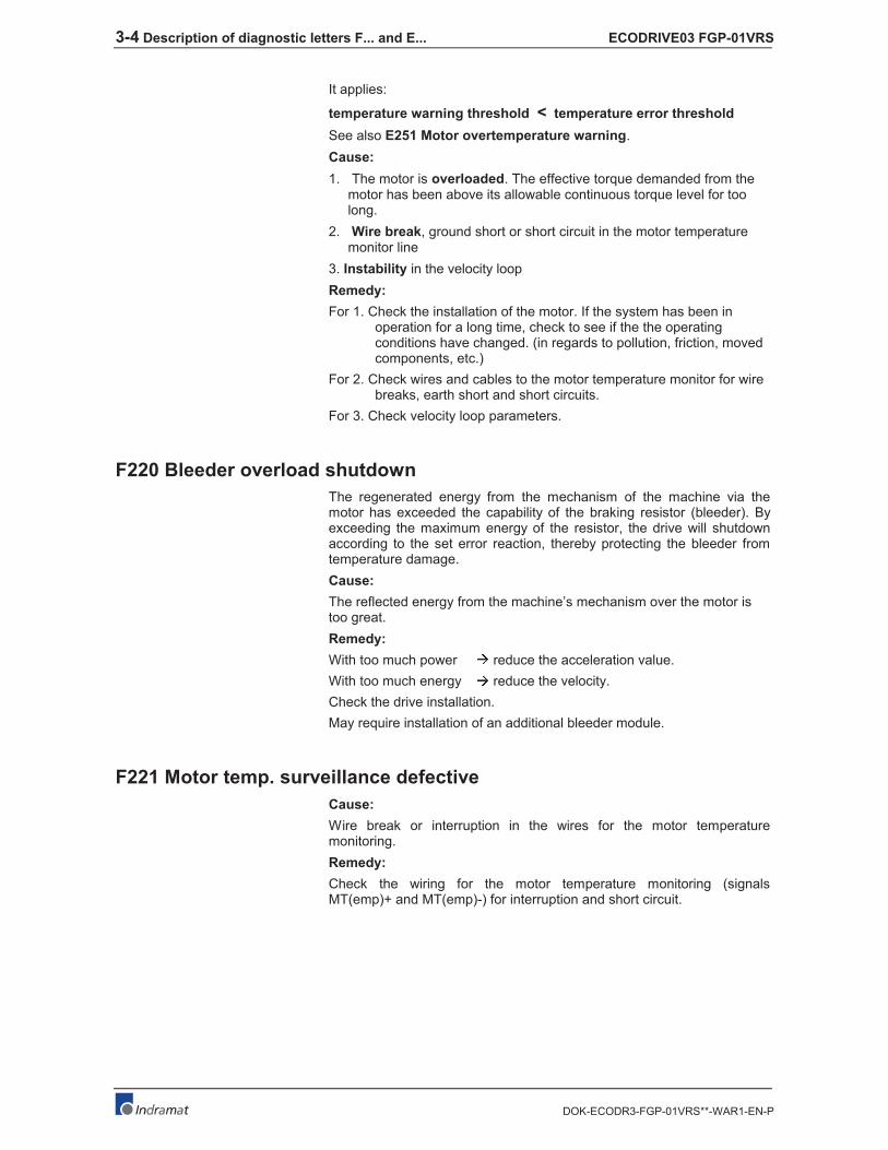
The analog signals of an external measurement system are used for highresolution analysis of that measurement system. These are monitoredaccording to two criteria:
1. The pointer length, which is calculated from the sine and cosinesignals, must be at least 1 V.
2. The maximum pointer length resulting from the sine and cosinesignals must not exceed 11.8 V.
pointer length = +sin cos2 2
Fig. 3-5: Pointer length
3-8 Description of diagnostic letters F... and E... ECODRIVE03 FGP-01VRS
DOK-ECODR3-FGP-01VRS**-WAR1-EN-P
Fig. 3-6: Correct signal amplitude
Example:
Ucos = -6.5V
Usin = 6.5V
( )pointer length V V V= - +65 65 922 2
. . .≈
Remedy:
1. Check the measurement system cable.
2. Check the measurement system.
F245 Encoder 2 failure: quadrant error
The evaluation of the additional optional encoder (encoder 2) is active. Inthe evaluation of the sinusoidal input signals of the optional encoder, aplausibility check is performed between these signals and the counter fedby these signals. Doing this, an error has been encountered.
Cause:
1. Defective encoder cable
2. Disruptive electro-magnetic interference on the encoder cable
3. Defective encoder interface
Remedy:
For 1. Exchange the encoder cable.
For 2. Keep the encoder cable well away from power cables.
For 3. Exchange the encoder interface (DIAX) or the device (Ecodrive).

ECODRIVE03 FGP-01VRS Description of diagnostic letters F... and E... 3-9
DOK-ECODR3-FGP-01VRS**-WAR1-EN-P
F246 Max signal frequency of encoder 2 exceeded
The signal frequency of the encoder 2 (optional encoder) is checkedwhether the allowed max. frequency of the encoder interface isexceeded.
Whether, in the case of an excessive frequency, the error F246, Maxsignal frequency for encoder 2 exceeded is generated or not, depends
on the setting in the parameter P-0-0185, Function of encoder 2. If thenumber 4 for spindle encoder is set there, only the position status of the
optional encoder is cleared to 0. In the other case, the warning F246 isgenerated and the position status is cleared to 0.
F248 Low battery voltage
Cause:
For motors of series MKD and MKE, the absolute position information isstored by a battery-powered electronic in the motor feedback. The batteryis designed for a 10-year life span. If the battery voltage falls below 2.8 V,this message appears. The absolute encoder function will still bepreserved for about 2 weeks.
CAUTION
Malfunction in the control of motors and moving
elements
Possible damages: Mechanical injuries
⇒ Replace the battery as soon as possible.
Instructions for Exchanging Batteries
Have the following tools and accessories ready:
• Torx screwdriver size 10
• Needle-nose pliers, torque wrench
• New packaged battery (Part No. 257101)
CAUTION
Malfunction in the control of motors and moving
elements
Possible damages: Mechanical injuries
⇒ Turn off the power supply. Make sure it will not beturned back on. Exchange the battery while thecontrol voltage (24V) is turned on.
If the control voltage is turned off while the battery is taken out, the
absolute reference point will be lost. Then, the reference point must be
reestablished with the command "Set absolute measuring“.
Removing the Battery
• Unscrew torx screws (1) with size 10 screwdriver.
• Pull out the resolver feedback (RSF) lid by hand.
• Pull off the battery connector (2).
• Loosen battery clamp (3) and remove the battery.
• Place the prepared battery in the housing and screw on the clamp.
Attention! Do not kink or clamp the battery cable.
• Attach the connector (2) of the battery.
Close the resolver feedback lid, screw in 4 torx screws (1) and tighten to1.8 Nm with the torque wrench.

3-10 Description of diagnostic letters F... and E... ECODRIVE03 FGP-01VRS
DOK-ECODR3-FGP-01VRS**-WAR1-EN-P
F253 Incr. encoder emulator: pulse frequency too high
Cause:
The incremental encoder emulator can process a maximum of 1023 linesper sample period (250 µs); this value has been exceeded.
Remedial action:
1. Reduce the number of lines of the incremental encoderemulator (P-0-0502).
or
2. Reduce the travel velocity.
F267 Erroneous internal hardware synchronization
Cause:
The drive control is synchronized on the bus interface (SERCOS,Profibus, Interbus, ...). The correct fuction of the synchronization ismonitored. If the average value of the deviation exceeds 5 µs, this erroris generated.
Remedy:
Replace drive controller.
F276 Absolute encoder out of allowed window
When turning off the drive controller with an absolute encoder (multiturn),the actual feedback position will be stored. When powered up, theabsolute position given by the encoder is compared with the stored
position. If the deviation is greater than the paramaterized P-0-0097,
Absolute Encoder Monitoring Window, the error F276 will appear andbe given to the control system.
Cause:
1. Turning on for the first time (invalid stored position)
2. The motor has been moved further than allowed by theparameter in the absolute encoder monitoring window, P-0-0097,while it was turned off.
3. Incorrect position initialization
Remedy:
For 1. Press S1 to reset the error and set the absolute position.
For 2. The motor was moved while turned off and sits outside of itspermissible position. Check to see if the displayed position iscorrect in relation to the machine zero point. Reset subsequenterrors.
For 3. An accident may occur by accidental shaft movement.Check absolute position information. The feedback is defective ifthe absolute position information is wrong. The motor should beexchanged and sent to the INDRAMAT Customer Service.

ECODRIVE03 FGP-01VRS Description of diagnostic letters F... and E... 3-11
DOK-ECODR3-FGP-01VRS**-WAR1-EN-P
F277 Current measurement trim wrong
This error can only happen during the test of the drive controller at theINDRAMAT factory.
The current measurement in the drive controller is calibrated preciselywith a test current in the INDRAMAT test department. During this test,correction values outside the projected tolerances have come out.
Cause:
1. Hardware defective in the drive controller
2. The correct current for the calibraton does not flow.
Remedy:
1. Repair the control board.
2. Check the calibration current.
F281 Mains fault
Cause:The power supply voltage was not present during operation for at least 3power periods. As a result, the drive controller was brought to a standstillaccording to the set error response.
Remedy:
Check the power supply connection according to the project planningspecifications.
F386 No ready signal from supply module
Cause:
The input BbN „operation readiness from supply unit“ at the drivecontroller is at 24V, that means the connected mains supply unit does notreport ready for operation.
F402 Double MDT failure shutdown
The Master Data Telegram (MDT) has not been received in twosuccessive SERCOS or field bus cycles of the drive.
Cause:
1. Optic fibre-bus: Optical link corrupted.
2. Optic fibre bus: Too high damping of the light signals
3. SERCOS: Error in the SERCOS Interface (general)
4. Field bus: Bus connection interrupted/locked up for longer thanwatchdog time.
5. The bus-master does not send cyclical telegrams any more tothe drive. However, these are mandatory in phase 4.
Remedy:
For 1. Check all the fibre optic connections in the SERCOS ring.
For 2. Measure the damping/absorption of the optical cables.
The max. loss between TX and RX may not exceed 12,5 dB!
For 3. Replace the SERCOS Interface module in the drive.
For 4. Check the field bus connectors and wiring, signal levels.
For 5. Switch on the master and get the cyclical communication going,see manual for your control.

3-12 Description of diagnostic letters F... and E... ECODRIVE03 FGP-01VRS
DOK-ECODR3-FGP-01VRS**-WAR1-EN-P
F407 Error during initialisation of master communication
Upon every power-up, the master communication link between drive
processor and field bus processor is checked. Doing this, the version
of the field bus firmware is examined, and a communication checkbetween the two microcontrollers is performed. If this communication isnot established properly, the initialization will be finished with this errormessage.
F434 Emergency-Stop
Pressing the emergency stop switch (E-Stop) has caused the drive to
perform the emergency stop function that was selected in the P-0-0119,
Best possible deceleration parameter. Setting bit 15 of S-0-0011,
Class 1 diagnostics causes an error message to be issued to thecontroller.
Cause:
The emergency stop switch has been pressed.
Remedy:
Eliminate the malfunction that has caused the emergency switch to beactuated, and clear the error.
F629 Positive travel limit exceeded
The drive has received a command value which has led to an axisposition outside the positive travel range. The axis has been brought to astandstill with the error response "Set velocity command value to zero".
Bit 2 of paramater P-0-0090, Travel limit parameter is set for"Exceeding travel range is an error", or after exceeding the position limita drive control command has been started (such as the drive-controlledhoming procedure).
Cause:
S-0-0049, Positive position limit value exceeded.
Remedy:
1. Check S-0-0049, Positive position limit value
2. Check the software limits of the control system
3. Activate the axis after the error response
Procedure:
• Clear the error.
• If the power supply was turned off, turn it back on.
• Move the axis into the permissible working range.
Note: Only such command values will be accepted which lead backinto the allowed working range. With other command values, the
drive will stop again. - The parameter S-0-0057, Position
window defines a hysteresis for the travel limits.
F630 Negative travel limit exceeded
The drive has received a command value which has led to an axisposition outside the negative travel range. The axis has been brought toa standstill with the error response "Set velocity command value to zero".
Bit 2 of paramater P-0-0090, Travel limit parameter is set for"Exceeding travel range is an error", or after exceeding the position limit

ECODRIVE03 FGP-01VRS Description of diagnostic letters F... and E... 3-13
DOK-ECODR3-FGP-01VRS**-WAR1-EN-P
a drive control command has been started (such as the drive-controlledhoming procedure).
Cause:
S-0-0050, Negative position limit value exceeded.
Remedy:
1. Check S-0-0050, Negative position limit value.
2. Check the software limits of the control system.
3. Activate the axis after the error response.
Procedure:
• Clear the error.
• If the power supply was turned off, turn it back on.
• Move the axis into the permissible working range.
Note: Only such command values will be accepted which lead backinto the allowed working range. With other command values, the
drive will stop again. - The parameter S-0-0057, Position
window defines a hysteresis for the travel limits.
F634 Emergency-Stop
Pressing the emergency stop (E-Stop) switch has caused the drive tostop by setting the velocity command value to zero. An error is reported
in the S-0-0011, Class 1 diagnostics parameter.
Cause:
The emergency stop switch has been pressed.
Remedy:
Eliminate the malfunction that has caused the emergency switch to beactuated, and clear the error.
F643 Positive travel limit switch detected
The positive travel limit switch has been encountered. The axis has beenbrought to a standstill with the "Set velocity command value to zero" errorresponse.
Bit 2 of parameter P-0-0090, Travel limit parameter is set for"Exceeding travel range as error", or a drive control command has beenstarted (such as the drive-controlled homing procedure) with the limitswitch already actuated.
Cause:
The positive travel limit switch is detected.
Remedy:
1. Reset the error.
2. Turn the power supply on again.
3. Move the axis into the permissible travel range.
Note: The drive will not accept command values which lead out of thepermissible travel range. Entering these command values in thedrive controller will result in this error.

3-14 Description of diagnostic letters F... and E... ECODRIVE03 FGP-01VRS
DOK-ECODR3-FGP-01VRS**-WAR1-EN-P
F644 Negative travel limit switch detected
The negative travel limit switch has been encountered. The axis hasbeen brought to a standstill with the "Set velocity command value to zero"error response.
Bit 2 of parameter P-0-0090, Travel limit parameter is set for"Exceeding travel range as error", or a drive control command has beenstarted (such as the drive-controlled homing procedure). with the limitswitch already actuated.
Cause:
The negative travel limit switch is detected.
Remedy:
1. Reset the error.
2. Turn the power supply on again.
3. Move the axis into the permissible travel range.
Note: The drive will not accept command values which lead out of thepermissible travel range. Entering these command values in thedrive controller will result in this error.
F822 Encoder 1 failure: signal too small
For the high resolution evaluation of a position encoder, the analogsignals of the transducer are used. These are monitored for 2 criteria:
1. The pointer length resulting from sine and cosine signal must be > 1
V.
2. The max. pointer length from sine and cosine signal must not exceed11.8 V.
Pointerlength = +sin ² cos ²
Fig. 3-7: : Pointer length
Fig. 3-8: : Correct signal amplitude

ECODRIVE03 FGP-01VRS Description of diagnostic letters F... and E... 3-15
DOK-ECODR3-FGP-01VRS**-WAR1-EN-P
Example:
Ucos = -6,5V
Usin = 6,5V
Pointerlength V V V= − + =( , )² ( , )² ,6 5 6 5 9 2
Note: The error cannot be cleared in communication phase 4(operating mode). Before clearing the error, you are obliged toswitch to communication phase 2 (parameter mode).
Causes:
1. Feedback Cable defective
2. Transmission of the feedback signals disturbed
3. Feedback defective
Remedies:
1. Check the cable to the measuring system
2. Place the cable apart from the motor power cable. The screen mustbe connected to the housing of the drive controller.
3. Check the measuring system; replace it, if necessary.
F860 Overcurrent: short in power stage
The current in the power transistor bridge has exceeded twice the peakcurrent of the drive. As a result, the drive will immediately switched to atorque-free state. An optional brake is immediately activated.
Cause:
1. Short circuit in the motor cable.
2. Defective power section of the drive controller
3. The current regulator was parameterized with wrong values.
Remedy:
For 1. Check the motor cable for a short.
For 2. Exchange the drive controller.
For 3. The current regulator parameters should not deviate from thedefault values of the feedback.
F870 +24Volt DC error
The drive controller requires a 24-V control voltage. The drive's torque isreleased immediately when the maximum permissible tolerance of+-20% is exceeded. An optional blocking brake is activated.
Cause:
1. Defective cable for the control voltages.
2. 24-V power supply overload.
3. Defective power supply unit.
4. Short-circuit in the emergency stop circuit.

3-16 Description of diagnostic letters F... and E... ECODRIVE03 FGP-01VRS
DOK-ECODR3-FGP-01VRS**-WAR1-EN-P
Remedy:
Ref. 1. Check and, if necessary, replace the cable and connections of thecontrol voltages.
Ref. 2. Check the 24-V power at the power supply unit.
Ref. 3. Check the power supply unit.
Ref. 4. Check the emergency stop circuit for a short-circuit.
Note: This error can only be cleared in parametrization mode(phase 2). As a result of this error, the encoder emulation isswitched off.
F873 Power supply driver stages fault
The voltage supply of the driver stage is monitored, and if the voltage istoo low, the drive is turned off.
Cause:
The voltage supply of the driver stage is too low.
Remedy:
Exchange drive controller.
F878 Velocity loop error
The velocity loop monitor will appear when the following conditions occursimultaneously:
• The current command value is at the peak current limit.
• The difference between the actual velocity and the command velocityis greater than 10 % of the maximum motor velocity.
• actual speed > 1.25 % of maximum speed
• Command and actual acceleration have different qualifying signs.
Cause:
1. Motor cable is connected incorrectly.
2. Defective controller section of the drive
3. Defective feedback
4. Velocity loop paramaterized incorrectly
5. Incorrect commutation offset
Remedy:
For 1. Check the motor cable connection.
For 2. Exchange the drive controller.
For 3. Exchange the motor.
For 4. Check the velocity controller to see whether it is withinoperational parameters.
For 5. Exchange the motor.
F879 Velocity limit S-0-0091 exceeded
In torque control, the actual velocity is monitored. This error is generated
if the programmed velocity in the S-0-0091, Bipolar velocity limit valueparameter is exceeded by the 1.125-fold value or a minimum of 100 rpm(rotary motor) or by 100 mm/min (linear motor).

ECODRIVE03 FGP-01VRS Description of diagnostic letters F... and E... 3-17
DOK-ECODR3-FGP-01VRS**-WAR1-EN-P
Cause:
The torque command value was for too long a time greater than the loadtorque. This causes the actual speed to increase up to the maximumpossible motor speed.
Remedy:
Assign the correct torque command value for the required task. Reduce
the S-0-0092, Bipolar torque/force limit value parameter value.
F895 4kHz fault
The 4 kHz signal is synchronized with the software processing forcreation of the resolver signal. This error message is created whensynchronization occurs improperly.
Cause:
1. The synchronization of the resolver controller voltage is invalid inregards to the software.
2. The error can be caused by an electrical discharge.
Remedy:
For 1. Exchange the drive controller and return it for testing.
For 2. Cycle the power (off and on again). If this is not successful,exchange the drive controller.

3-18 Description of diagnostic letters F... and E... ECODRIVE03 FGP-01VRS
DOK-ECODR3-FGP-01VRS**-WAR1-EN-P
3.2 Warning diagnostic messages
E221 Warning Motor temp. surveillance defective
Temperature monitoring checks to see if the measured motortemperature is within reasonable bounds. If it determines that it is lower
than -10°C, then it is assumed the measuring unit is defective. Warning
E221 Warning Motor temp. surveillance defective will appear for 30seconds. Afterwards the drive controller will be brought to a standstill
according to the selected error response and message F221 Error
Motor temp. surveillance defective will be generated.
Cause:
1. Motor temperature sensor not connected.
2. Broken cable.
3. Defective sensor.
4. Broken cable in drive controller.
Remedy:
For 1. Connect the sensor to the drive controller and to the motor(see project planning specifications for the motor).
For 2. Exchange the wiring between the drive controller and the motor.
For 3. Exchange the motor.
For 4. Exchange the drive controller.
E225 Motor overload
The maximum possible motor current is reduced in order to protect themotor from being destroyed.
If a current flows in the that is greater than 2.2 times the motor current atstandstill S-0-0111, the maximum possible motor current (motor peakcurrent S-0-0109) is reduced. With 4-fold motor current at standstill, thereduction starts after 400 ms. With 5-fold current it starts earlier, and with3-fold current later.
The E225 Motor overload warning is issued when the motor peakcurrent is reduced by the limitation.
The reduction also has an effect on the active permanent current P-0-4045.
E226 Undervoltage in power section
If bit 5 of the P-0-0118, Power off on error parameter has been set, anundervoltage condition will be handled as a nonfatal warning. The driveissues this warning if the drive enabling signal is present and the DC busvoltage message disappears.
Cause:
Power supply unit is switched off or mains failure occurs while the driveenabling signal is set.
Remedy:
Switch off the drive enabling signal before you switch off the powersupply unit.

ECODRIVE03 FGP-01VRS Description of diagnostic letters F... and E... 3-19
DOK-ECODR3-FGP-01VRS**-WAR1-EN-P
E231 No jogging direction selected
During jog operation to the position limit, this warning is generated, whenno unambiguous direction for jogging is selected. This happens, when
the parameter P-0-4056 Jog inputs contains the value 00b or 11b.
Remedy:
Select an unambiguous jogging direction, either positive or negative, inP-0-4056 or, with parallel interface, via the hardware inputs.
E247 Interpolation velocity = 0
The drive-internal position command value interpolator is active if
• the "drive-internal interpolation" mode,
• the "relative drive-internal interpolation" mode,
• drive-controlled homing,
• drive halt
is active.
The E247 warning is issued if the employed velocity specification is 0.Possible velocity specifications are:
• S-0-0259, Positioning Velocity
• S-0-0041, Homing velocity
• S-0-0091, Bipolar velocity limit value
E248 Interpolation acceleration = 0
Cause:
The drive internal position command interpolator (profile generator) isactive. It has been given the acceleration = 0. Without acceleration, it cannever reach a given speed.
Operation modes with drive internal position command generation:
1. Drive-internal interpolation
2. Relative drive-internal interpolation
3. Drive-controlled homing
4. Drive Halt
5. Process block mode
Remedy:
Input a reasonable value > 0 for the employed acceleration. Possibleacceleration specifications, depending from the operation mode, are:
For 1. and 2.: S-0-0260, Positioning acceleration >0
For 3.: S-0-0042, Homing acceleration >0
For 4.: S-0-0138, Bipolar acceleration limit value >0
For 5.: P-0-4008, Process block Acceleration >0

3-20 Description of diagnostic letters F... and E... ECODRIVE03 FGP-01VRS
DOK-ECODR3-FGP-01VRS**-WAR1-EN-P
E249 Positioning velocity S-0-0259 > S-0-0091
Cause:
In the operation modes "Drive-internal interpolation" and "Relative drive-
internal interpolation", the velocity specified in the S-0-0259, Positioning
velocity parameter is used for positioning. In the "process block“operation mode, this velocity is taken for positioning with limited speed.
If velocity specified there is greater than value in S-0-0091, Bipolar
velocity limit value, the message E249 is generated. Then, bit 5 is set
in S-0-0012, Class 2 diagnostics.
Note: The warning E249 is only generated when the parameterS-0-0259 is transferred cyclically via the commandcommunication (SERCOS, Profibus-DP, Interbus, ...).
Remedy:
Reduce S-0-0259, Positioning Velocity or, for process block mode,
S-0-4007, Process block Velocity.
E250 Drive overtemp. prewarning
The temperature of the heatsink in the drive controller has reached themaximum permissible temperature. The drive controller follows thecommand value input for a period of 30 seconds. This makes it possibleto bring the axis to a standstill with the control system while keeping trueto the process (for example, close the operation, leave the collision area,etc.).
After 30 seconds, the response set in parameter P-0-0119, Best
possible deceleration will be performed by the drive controller.
Cause:
1. Failure of the drive's internal blower.
2. Failure of the control cabinet's climate control.
3. Incorrect control cabinet dimensioning in regards toheat dissipation.
Remedy:
For 1. If the blower fails, exchange the drive controller.
For 2. Install climatization feature in the cabinet.
For 3. Check the dimensions of the control cabinet.
E251 Motor overtemp. prewarning
As soon as the temperature warning threshold (145°C) is exceeded,the warning E251 is output, and the drive keeps on following thecommand value.
This state can last for a long time without powering down. Only when the
temperature error threshold is exceeded, an immediate powering downwill take place.
See also F219 Motor Overtemperature Shutdown.
Cause:
The motor is overloaded. The effective torque required from the motorwas above the allowable standstill continuous torque for too long.

ECODRIVE03 FGP-01VRS Description of diagnostic letters F... and E... 3-21
DOK-ECODR3-FGP-01VRS**-WAR1-EN-P
Remedy:
Check the installation of the motor. For systems which have been in usefor a long time, check to see if the drive conditions have changed (inregards to pollution, friction, moving components, etc).
E252 Bleeder overload prewarning
Cause:
The braking resistance (bleeder) in the amplifier is charged with thereflected energy from the motor by about 90%. The bleederovertemperature warning shows that an overload of the bleeder isexpected if the feedback energy increases on and on.
Remedy:
Reduce the acceleration value or velocity. Check the drive installation.
E253 Target position out of travel range
In operation modes with drive ontrolled interpolation, the drive checks
before the move whether the specified S-0-0258, Target position, iswithin the possible travel range of the drive. This range is defined by the
parameters S-0-0049, Positive position limit value and S-0-0050,
Negative position limit value. The position limit check is activated in
the parameter S-0-0055, Position polarities with bit 4.
Cause:
The target position lies beyond the position limits, and the position limitcheck is activated.
Results:
• This warning message, E253, appears.
• The drive stops.
• The drive does not accept the target position or the process block.
• In S-0-0012, Class 2 diagnostic warning bit 13 is set.
Remedy:
1. For the Drive controlled interpolation mode, input the S-0-0258,
Target position only within the position limits.
2. For the Relative drive controlled interpolation mode, do the same,outgoing from the actual position.
3. For the Process block mode, input the S-0-4006 Process block
target position only within the position limits.
4. For relative process blocks, do the same, outgoing from the actualposition.
5. Check the position limit values. Moreover, the positive position limitvalue must be greater than the negative position limit value.
6. If you don’t need the position limit check, de-activate it, e.g. in modulomode.
E254 Not homed
If absolute positions are selected while in a positioning operation mode,the control drive must be homed to a reference position. If this is not thecase, an absolute position cannot be reached. The drive rejects thispositioning command and stops. The warning E254 will be given.

3-22 Description of diagnostic letters F... and E... ECODRIVE03 FGP-01VRS
DOK-ECODR3-FGP-01VRS**-WAR1-EN-P
Cause:
Absolute positioning was selected without the drive being referenced.
Remedies:
1. Do the homing (referencing) command with the drive or
2. do only relative positioning.
E255 Feedrate-override S-0-0108 = 0
With the parameter S-0-0108, Feedrate override, the travel velocity ofall in drive-controlled travel commands can be changed proportionally(in %).
If the value of this parameter is 0, the travel velocity is also 0. Withvelocity = 0, however, the drive can never go anywhere. It cannot followthe applied command values.
Causes:
1. The parameter S-0-0108, Feedrate override is 0.
2. S-0-0259, Positioning Velocity is 0.
3. The P-0-4007, Process block velocity is 0 with the selected processblock.
4. For devices with analog inputs: Feedrate override via analog input isactivated, and the voltage there is 0.
5. The feed potentiometer of the connected control system is at 0 or isbeing evaluated incorrectly. Like 4.
Remedies:
For 1.: Set Feedrate override > 0, so that the drive moves. Full speed isattained with 100% .
For 2.: Set S-0-0259 to the suitable value > 0 for your application.
For 3.: Set P-0-4007 to the suitable value > 0 for your application.
For 4.: Apply a voltage > 0 proportional to the desired speed,+10V corresponds to 100 % (full) speed.Alternative: De-activate Feedrate override.
For 5.: Turn the feed potentiometer cautiously, check the analog signaland the evaluation for it.
E256 Torque limit = 0
Cause:
1. For protection against mechanical overload, the maximum torque
can be limited by the S-0-0092, Bipolar torque/force limit valueparameter. If the actual value of this parameter is equal to 0, themotor does not develop torque and does not follow the givencommand values.
2. Torque reduction is set via an analog channel, and the appliedvoltage amounts to 10 V.
Remedy:
For 1. Set the torque limit to a value greater than 0.
For 2. Establish an analog voltage smaller than 10 V.

ECODRIVE03 FGP-01VRS Description of diagnostic letters F... and E... 3-23
DOK-ECODR3-FGP-01VRS**-WAR1-EN-P
E257 Continuous current limit active
The drive controller sets the peak current available for 400 ms.Thereafter, the continuous current limit becomes active and dynamicallylimits the peak current to the continuous current.
Cause:
More continuous torque was required than was available.
Remedy:
1. Check the drive installation.
2. Check the installation of the motor. For systems which have been inuse for a long time, check to see whether the drive conditions havechanged in regards to
• pollution
• friction
• moved masses
E258 Selected process block is not programmed.
Cause:
A positioning block was selected for which there is no set target positionor positioning velocity, etc.
Remedy:
Select another positioning block or enter the required data.
E259 Command velocity limit active
In the position control and velocity control operating modes, the effective
velocity command value is limited to the value in parameter S-0-0091,
Bipolar velocity limit value. The warning is given if the resulting velocitycommand value reaches this limit.
Cause:
Parameter S-0-0091, Bipolar velocity limit value was set too low.
Remedy:
In normal operating conditions, set parameter S-0-0091, Bipolar
velocity limit value to a value 10% greater than the NC effectivevelocity.
E261 Continuous current limit prewarning
Digital drives are monitored by a continually operating temperaturemodel. If the thermal load reaches 100%, the continuous current limit willbe activated shortly thereafter.Before the torque is reduced, a continuous current limit early warning is
given via a switching threshold, which is determined by parameter P-0-
0127, Overload warning.
To deactivate the warning, enter P-0-0127 = 100% into the parameter.

3-24 Description of diagnostic letters F... and E... ECODRIVE03 FGP-01VRS
DOK-ECODR3-FGP-01VRS**-WAR1-EN-P
Cause:
The drive controller was overloaded.
Remedy:
1. Check the drive layout.
2. Reduce acceleration.
3. Increase the switching threshold in parameter
P-0-0127, Overload warning
4. With systems which have been used for longer periods of time,check to see if drive controller conditions have changedin regards to:
- Friction
- Components which have been moved
- Feed during processing.
E263 Velocity command value > limit S-0-0091
Cause:
The value given to the drive for S-0-0036, Velocity command value wasgreater than permissible.
Remedy:
It is limited to S-0-0091, Bipolar velocity limit value.
E264 Target position out of num. range
Cause:
When using the operating mode "position control with process blocks",the target position of the selected additive process block will be verifiedto see whether it lies within the numerical range. This was not the case.
Remedy:
1. Check the target position and correct if necessary.
2. Select the position data display in modulo format.
E300 Processor watchdog
The processor in the drive controller is equipped with a watchdog. Insidethe drive controller, the processor must show activity regularly.
What has happened?
The wachdog time has elapsed, but the processor has not shown activityduring this time. A safe running of the firmware program is no moreguaranteed.
Cause:
The processor has been overloaded, or a severe mistake in the
firmware has occured. The result is that the processor does not docertain interrupt service routines any more.
Remedy:
Please contact the INDRAMAT customer service. Explain exactly, underwhich circumstances the error has occured. The firmware should beexchanged.

ECODRIVE03 FGP-01VRS Description of diagnostic letters F... and E... 3-25
DOK-ECODR3-FGP-01VRS**-WAR1-EN-P
E401 Error in the parameter channel
Cause:
In the parameter channel of the field bus (profibus), an error hasoccurred.
E402 Error in the process data channel
Cause:
In the process data channel of the field bus (profi bus), an error hasoccurred.
E403 Error in the FMS channel
Cause:
In the FMS channel of the field bus (profi bus), an error has occurred.
E404 Error during field bus command
Cause:
During execution of a field bus command, an error has occurred.
E408 Invalid addressing of MDT-data container A
This warning indicates an error during the index check in the multiplex
channel. During the cyclical data exchange, the index for the access to
the list S-0-0370, Configuration list for the MDT data containersurveyed, whether it points to a non-initialised field in the list. If it does,this warning is generated.
E409 Invalid addressing of AT-data container A
This warning indicates an error during the index check in the multiplex
channel. During the cyclical data exchange, the index for the access to
the list S-0-0371 is surveyed, whether it points to a non-initialised field inthe list. If it does, this warning is generated.
E825 Overvoltage in power stage
The DC bus voltage is too high.
Cause:
1. During braking (decelerating): the energy reflected from themechanical system via the motor was so high for a moment that itcould not be sufficiently dissipated to heat by the braking resistor(bleeder). The regenerated current could not be drained and thereforecharged the DC bus, so that the voltage there has become too high.
2. The mains voltage (AC input) is too high.

3-26 Description of diagnostic letters F... and E... ECODRIVE03 FGP-01VRS
DOK-ECODR3-FGP-01VRS**-WAR1-EN-P
Result:
In case of overvoltage, the motor is switched to torque-free operation.As soon as the DC Bus voltage falls again below the maximum allowablevalue, the controller will be turned on again.
Remedy:
For 1. Reduce the acceleration values.Check the drive controller layout, if necessary.Install an auxiliary bleeder, if necessary.
For 2. Check the mains supply voltage (AC/3phase).
WARNING
⇒ Danger of high-voltage shock!Care for protection against accidental touch.
E826 Undervoltage in power section
If the bit 3 is set in the parameter P-0-0118, Power off on error, theundervoltage is treated as "fatal warning“ with shutdown of the driveoperation. If the drive enable is on at the same time, and the DC busvoltage indication goes down, the drive displays this warning.
Cause:
Switching off the power supply or mains failure while the drive enable ison.
Remedy:
Switch off the drive enable before switching off the supply unit.
E829 Positive position limit exceeded
The drive has received a command value which resulted in an axisposition outside the positive travel range. The axis has been brought to astandstill by setting the velocity command to zero. A class 1 diagnosticerror is not generated. The drive will automatically follow commandvalues that lead back into the allowed range. "Handle travel range
exceeded as warning" is set in bit 2 of parameter P-0-0090, Travel limit
parameter.
Cause:
S-0-0049, Positive position limit value exceeded.
Remedy:
Enter command values which lead back into the allowed range.
Note: Only such command values will be accepted that lead back intothe allowed working range. With other command values, the
drive will stop again. - The parameter S-0-0057, Position
window defines a hysteresis for the travel limits.

ECODRIVE03 FGP-01VRS Description of diagnostic letters F... and E... 3-27
DOK-ECODR3-FGP-01VRS**-WAR1-EN-P
E830 Negative position limit exceeded
The drive has received a command value which resulted in an axisposition outside the negative travel range. The axis has been brought toa standstill by setting the velocity command to zero. A class 1 diagnosticerror is not generated. The drive will automatically follow commandvalues which lead into the allowed range. "Handle travel range exceeded
as warning" is set in bit 2 of parameter P-0-0090, Travel limit
parameter.
Cause:
S-0-0050, Negative travel limit value exceeded.
Remedy:
Enter command values which lead back into the allowed range.
Note: Only such command values will be accepted that lead back intothe allowed working range. With other command values, the
drive will stop again. - The parameter S-0-0057, Position
window defines a hysteresis for the travel limits.
E831 Position limit reached during jog
If the position limit monitor is activated and the drive is “INREFERENCE", then it will be positioned on the position limit duringmovement by jogging. If the drive is positioned on the position limit orbeyond the position limit, the drive stops and signals "Position limit valuereached during jog".
Remedies:
1.Move the motor back within the allowed travel area with the jogfunction or
2. Turn off the position limit monitor.
E834 Emergency-Stop
Pressing the emergency stop switch has caused the drive to perform the
emergency stop function that had been selected via the P-0-0119, Best
possible deceleration parameter. There is no error message issued tothe controller.
Cause:
The emergency stop switch was pressed.
Remedy:
Eliminate the malfunction that led to the activation of the emergency stopswitch. The warning will then disappear.
E843 Positive limit switch activated
The drive has received a command value which resulted in an axisposition outside the positive travel range. The axis has been brought to astandstill by setting the velocity command to zero. A class 1 diagnosticerror is not generated. The drive will automatically follow command
values that lead back into the allowed range. Bit 2 of P-0-0090, Travel
limit parameter is set to "Overtravelling is handled as a warning".

3-28 Description of diagnostic letters F... and E... ECODRIVE03 FGP-01VRS
DOK-ECODR3-FGP-01VRS**-WAR1-EN-P
Cause:
The positive limit switch has been actuated.
Remedy:
Enter command values that lead back into the allowed range.
E844 Negative limit switch activated
The drive has received a command value which resulted in an axisposition outside the negative travel range. The axis has been brought toa standstill by setting the velocity command to zero. A class 1 diagnosticerror is not generated. The drive will automatically follow command
values that lead back into the allowed range. Bit 2 of P-0-0090, Travel
limit parameter is set to "Overtravelling is handled as a warning".
Cause:
The negative limit switch has been actuated.
Remedy:
Enter command values which lead back into the allowed range.

ECODRIVE03-FGP-01VRS Description of Diagnostic Letters C..., D... and A... 4-1
DOK-ECODR03-FGP-01VRS**-WAR1-EN-P
4 Description of Diagnostic Letters C..., D... and A...
4.1 Command Diagnostic Messages C... and D
The commands are used for control of complex features in the drive.
For example, the features "drive controlled homing procedure" or"Communication Phase 4 Transition Check" are defined as commands.
Commands can start, interrupt or erase a primary control.
A parameter belongs to each command whereby the command can becontrolled by the parameter.
During the command operation, the diagnostic message "Cx" appears inthe H1 display where the x stands for the number of the command.
It can distinguish between 3 types of commands.
• Drive Commands- Lead to an eventual automatic drive movement- Can be started only through an inputted control enable- Deactivates the active operating mode during its operation
• Monitor CommandsActivation or deactivation of monitors or features
• Management Commands- Lead management tasks that are not interruptable
Command Types

4-2 Description of Diagnostic Letters C..., D... and A... ECODRIVE03 FGP-01VRS
DOK-ECODR03-FGP-01VRS**-WAR1-EN-P
C100 Communication phase 3 transition check
The command S-0-0127, C1 Communication phase 3 transition
check has been activated.
C101 Invalid communication parameter (S-0-0021)
Cause:
Communications parameters which are needed to operate the drive incommunication phase 3 are invalid.
Remedy:
A list of the invalid parameters can be seen in parameter S-0-0021, IDN-
list of invalid op. data for comm. Ph. 2. The invalid parameters mustbe rewritten so they are correct.
C102 Limit error communication parameter (S-0-0021)
Cause:
Communications parameters, which are needed to operate the drive incommunication phase 3, are outside their limit values.
Remedy:
A list of the invalid parameters can be seen in parameter S-0-0021, List
of invalid op. data for comm. ph. 2. The invalid parameters must be
rewritten with values between the respective min. and the max. valueto be correct.
C104 Config. IDN for MDT not configurable
Cause:
Telegram type 7 was set in parameter S-0-0015, Telegram type
parameter. Parameters which are missing in S-0-0188, List of
configurable data in MDT are kept in S-0-0024, Configuration list for
the master data telegram.
Remedy:
You must either set a priority telegram (Telegram type = 0..6) or provide
S-0-0024, Config. list of master data telegram with parameters. These
parameters are also contained in S-0-0188, List of configurable data in
the MDT.
C105 Configurated length > max. length for MDT
Cause:
Telegram type 7 was set in parameter S-0-0015, Telegram type
parameter. The length of the configured record in MDT, which is
determined by S-0-0024, Configurations list of the master data
telegram, exceeds the maximum permissible length S-0-0186, Length
of the configurable data record in the MDT.

ECODRIVE03 FGP-01VRS Description of Diagnostic Letters C..., D... and A... 4-3
DOK-ECODR03-FGP-01VRS**-WAR1-EN-P
Remedy:
You must either set a priority telegram in S-0-0015, Telegram type
parameter (telegram type = 0..6 ) or reduce the number of configurableparameters in MDT.
C106 Config. IDN for AT not configurable
Cause:
Telegram type 7 was set in parameter S-0-0015, Telegram type
parameter. Parameters which are not contained in S-0-0187, List of
configurable data in AT can be seen in S-0-0016, Custom amplifier
telegram configuration list.
Remedy:
You must either set a priority telegram in parameter S-0-0015, Telegram
type parameter (telegram type = 0..6) or you must provide S-0-0016,
Custom amplifier telegram configuration list with parameters that are
contained in S-0-0187, List of configurable data in the AT.
C107 Configurated length > max. length for AT
Cause:
Message frame type 7 has been selected in S-0-0015, Telegram Type
Parameter. The length of the configured data record in the AT, that is
defined via S-0-0016, Custom amplifier telegram configuration list,
exceeds the maximum permissible S-0-0185, Length of the
configurable data record in the AT.
Remedy:
Either select the priority message frame via S-0-0015, Telegram Type
Parameter (message frame type = 0...6) or reduce the number of
configured parameters in the AT ( S-0-0016 ).
C112 TNcyc (S-0-0001) or TScyc (S-0-0002) error
Cause:
Only 500 us or even multiples of 1ms are permitted as valid values for S-
0-0001, NC Cycle time (TNcyc) and S-0-0002, SERCOS Cycle time
(Tscyc). Here, this is not the case.
Remedy:
S-0-0001, NC Cycle time (TNcyc) and S-0-0002, SERCOS Cycle time
(Tscyc) must be corrected. These parameters are determined by themanufacturer of the control system and are specified by the SERCOSinterface.
C113 Relation TNcyc (S-0-0001) to TScyc (S-0-0002) error
Cause:
The value of S-0-0001, NC Cycle time (TNcyc) can only be equal to or
be a multiple of S-0-0002, SERCOS Cycle time (Tscyc). Here this is notthe case.

4-4 Description of Diagnostic Letters C..., D... and A... ECODRIVE03 FGP-01VRS
DOK-ECODR03-FGP-01VRS**-WAR1-EN-P
Remedy:
S-0-0001, NC Cycle time (Tncyc) and S-0-0002, SERCOS Cycle time
(Tscyc) must be corrected. These parameters are determined by themanufacturer of the control system and are specified by the SERCOSinterface.
C114 T4 > TScyc (S-0-0002) - T4min (S-0-0005)
Cause:
The maximum permissible value for S-0-0007, Feedback acquisition
starting time (T4) is
S-0-0002, SERCOS Cycle time (Tscyc) -
S-0-0005, Minimum feedback acquisition
time(T4min)
The value for S-0-0007, Feedback acquisition starting time (T4) isincorrect.
Remedy:
Correct S-0-0007, Feedback acquisition starting time (T4). Theseparameters are determined by the manufacturer of the control systemand are specified by the SERCOS interface.
C118 Order of MDT configuration wrong
The chronological order of processing the cyclical MDT data in the driveis the same order in which the configurated ident numbers (IDN) are
placed in the parameter S-0-0024, Config. list of the master-data-
telegram.
If both parameters S-0-0360, MDT Data container A and S-0-0368,
Addressing for data container A as well are configured in the MDT,then the processing of the MDT data container is only correct if theaddressing has been processed before. To maintain the correct order forthe configuration of the MDT, the drive checks in the command S-0-
0127, C100 Communication phase 3 transition check, whether the IDN
S-0-0368 is configured before S-0-0360.
If this is not the case, the drive generates the command error C118
Order of MDT configuration wrong.
C200 Communication phase 4 transition check
Meaning:
The command S-0-0128, C200 Communication phase 4 transition
check has been activated.
C201 Invalid parameter(s) (->S-0-0022)
Cause:
Parameters which will be necessary to operate the drive incommunications phase 4 are invalid. The invalid parameters can be seen
in S-0-0022, IDN list of invalid op. data for comm. ph. 3.
Remedy:
The parameters of S-0-0022, IDN list of invalid op. data for comm. ph.
3 must be rewritten so they are correct.

ECODRIVE03 FGP-01VRS Description of Diagnostic Letters C..., D... and A... 4-5
DOK-ECODR03-FGP-01VRS**-WAR1-EN-P
C202 Parameter limit error (->S-0-0022)
Cause:
Parameters which are necessary to operate the drive in communicationsphase 4 are outside of their minimum or maximum input values, or theentered value can't be processed (for bit bars). The incorrect parameters
are listed in S-0-0022, IDN list of invalid op. data for comm. ph. 3.
Remedy:
The parameters of S-0-0022, IDN list of invalid op. data for comm. ph.
3 must be rewritten with correct values.
C203 Parameter calculation error (->S-0-0022)
Cause:
Parameters that are required for phase-4 operation (operating mode)cannot be processed in that way. The incorrect parameters are listed in
S-0-0022, IDN List of Invalid Op. Data for Comm. Ph. 3.
Remedy:
Write correct values to the parameters in S-0-0022, IDN List of Invalid
Op. Data for Comm. Ph. 3.
C204 Motor type P-0-4014 incorrect
An MHD-, MKD or MKE motor (value 1 or 5) is entered into parameter
P-0-4014, Motor type. The appropriate abbreviation "MHD", "MKD", or
"MKE" however, was not found in parameter S-0-0141, Motor type in themotor feedback data memory.
Cause:
1. Incorrect parameter set for type of motor.
2. The motor feedback memory cannot be read.
Remedy:
For 1. Enter the type of motor used in parameter P-0-4014, Motor type
For 2. Check feedback connection.If feedback is defective, exchange motor.
C207 Load error LCA
Cause:
Defective drive.
Remedy:
1. Power down and then on again.
2. If this in not successfull, exchange drive.
C208 Invalid SSI parameter (->S-0-0022)
Description:
When the motors are first distributed, the parameter for absolute controlemulation is purposely invalid to ensure that the "Set AbsoluteMeasurement Emulator Command" will be executed after a motor isexchanged.

4-6 Description of Diagnostic Letters C..., D... and A... ECODRIVE03 FGP-01VRS
DOK-ECODR03-FGP-01VRS**-WAR1-EN-P
Cause:
The SSI emulation was selected. The parameters required for emulationare invalid.
Remedy:
Connect the control drive to a PC and activate DriveTop.
"Actual Position Output" menu with controller emulation type "AbsoluteController Emulation (SSI)":
• Describe "Homing Position/Offset"
• Select "Absolute Control Directional Counter"
C210 Feedback 2 required (->S-0-0022)
Cause:
Values that require an optional encoder have been entered in S-0-0147,
Homing parameter or in the S-0-0032...35, Mode of Operation
parameters. However, 0 (not available) has been entered in the P-0-
0075, Feedback type 2, optional parameter.
The ident number of the parameter that requires the optional encoder is
entered in S-0-0022, IDN List of Invalid Op. Data for Comm. Ph. 3.
Remedy:
Modify S-0-0147, Homing parameter or the S-0-0032...35, Mode of
Operation parameters to utilization of the motor encoder instead ofoptional encoder.
Set P-0-0075, Feedback type 2, optional to a value different from 0 toactivate the optional measuring system.
C211 Invalid feedback data (->S-0-0022)
Invalid data has been encountered when the parameters stored in themotor feedback were read, or an error has occurred when the data wasread.
Causes:
1. Motor feedback cable not connected or defective
2. Motor feedback defective
3. Drive controller defective
Remedy:
Ref. 1. Check motor feedback cable; connect both sides
Ref. 2. Replace motor
Ref. 3. Replace amplifier
C212 Invalid amplifier data (->S-0-0022)
During drive initialization, the operating software fetches data from anEEPROM in the drive controller. This error message is generated afterthat access has failed.
Causes:
Defective hardware in the drive controller.
Remedy:
Replace drive controller.

ECODRIVE03 FGP-01VRS Description of Diagnostic Letters C..., D... and A... 4-7
DOK-ECODR03-FGP-01VRS**-WAR1-EN-P
C213 Position data scaling error
Cause:
The scaling parameters for position data permit the position data displayformat to be selected. The drive-internal position data format depends onthe employed motor encoder and the encoder resolution. The factor usedfor converting the position data from the drive-internal format into thedisplay format or vice versa is outside the processable range, becauseeither
• linear motor and rotary position scaling with motor reference, or
• rotary motor and linear position scaling with motor reference, or
• linear motor with modulo scaling has been selected; or
• the determined factor used for converting the position data from thedisplay format to the internal format, and vice versa, cannot berepresented.
Remedy:
Checking and correcting the relevant parameters, such as
• S-0-0076, Position data scaling type
• S-0-0077, Linear position data scaling factor
• S-0-0078, Linear position data scaling exponent
• S-0-0079, Rotational position resolution
• S-0-0116, Resolution of motor feedback
• S-0-0121, Input revolutions of load gear
• S-0-0122, Output revolutions of load gear
• S-0-0123, Feed constant
• P-0-0074, Feedback type 1
• S-0-0277, Position feedback 1 type parameter
C214 Velocity data scaling error
Cause:
The scaling parameters for velocity data permit the velocity data displayformat to be selected. The drive-internal velocity data format depends onthe employed motor encoder and the encoder resolution. The factor usedfor converting the velocity data from the drive-internal format into thedisplay format or vice versa is outside the processable range.
Remedy:
Checking and correcting the relevant parameters, such as
• S-0-0044, Velocity data scaling type
• S-0-0045, Velocity data scaling factor
• S-0-0046, Velocity data scaling exponent
• S-0-0116, Resolution of motor feedback
• S-0-0121, Input revolutions of load gear
• S-0-0122, Output revolutions of load gear
• S-0-0123, Feed constant
• P-0-0074, Feedback type 1
• S-0-0277, Position feedback 1 type parameter

4-8 Description of Diagnostic Letters C..., D... and A... ECODRIVE03 FGP-01VRS
DOK-ECODR03-FGP-01VRS**-WAR1-EN-P
C215 Acceleration data scaling error
Cause:
The display format of the acceleration data can be set using accelerationscaling parameters. The drive-controlled format of the acceleration datais dependent on what motor encoder and encoder resolution are used.The factor for converting acceleration data from internal drive format todisplay format (or vice-versa) is outside the workable range.
Remedy:
Check and set the relevant parameters correctly as follows:
• S-0-0160, Acceleration data scaling type
• S-0-0161, Acceleration data scaling factor
• S-0-0162, Acceleration data scaling exponent
• S-0-0116, Resolution of motor feedback
• S-0-0121, Input revolutions of load gear
• S-0-0122, Output revolutions of load gear
• S-0-0123, Feed constant
• P-0-0074, Feedback type 1
• S-0-0277, Position feedback 1 type parameter
C216 Torque/force data scaling error
Cause:
The display format of the torque/force data can be set using torque/forcescaling parameters. The factor for converting torque data from drive-controlled format to display format (or vice-versa) is outside the workablearea.
Remedy:
Check and set the relevant parameters correctly as follows:
• S-0-0086, Torque/force data scaling type
• S-0-0093, Torque/force data scaling factor
• S-0-0094, Torque/force data scaling exponent
• S-0-0110, Amplifier peak current
• S-0-0111, Motor current at standstill
C217 Feedback1 data reading error
All MKD und MHD motors have a data memory in the feedback unit.From there, settings for the encoder are read.
Cause:
During reading of the values from the feedback, an error has occurred.
Remedy:
Check feedback cable.
Change motor.

ECODRIVE03 FGP-01VRS Description of Diagnostic Letters C..., D... and A... 4-9
DOK-ECODR03-FGP-01VRS**-WAR1-EN-P
C218 Feedback 2 data reading error
The initializatin of the measuring systems is done in the command
S-0-0128, C200 Communication phase 4 transition check. If themeasuring system to initialize has an intrinsic data memory, this memoryis read.
The error C218 Feedback 2 data reading error is generated, if anadditional optional encoder (encoder 2) is present and being evaluated
(P-0-0075 Feedback type 2 other than 0) and if an error is discoveredwhile reading the data.
Measuring systems with intrinsic data memory are :
• DSF/HSF/LSF and resolver, as well as
• measuring systems with Endat interface (from Heidenhain)
Cause:
1. Defective measurement system cable
2. Defective measurement system
Remedy:
For 1. Check the measurement system cable.
For 2. Exchange the measurement system.
C220 Feedback 1 initializing error
A number of tests are performed when the motor encoder is initialized.An error was detected during this process. This error may be:
• Error while reading the angle rectification data
• Error while copying the angle rectification data
• Interruption of communication with the encoder
• Assembly error with the position of an initialization track
• Error while reading the analog signal of an initialization track
• Error in the pointer length of the analog signal of an initialization track
• Invalid offset between the high and low resolution track
• Error in the measuring system micro-controller
Cause:
1. Defective motor feedback cable
2. Defective motor feedback
3. Defective measurement system interface
Remedy:
For 1. Check the motor feedback cable.
For 2. Exchange the motor.
For 3. Exchange the measuring system interface, if it is a module, orthe complete drive controller.
C221 Feedback 2 initializing error
Several checks are performed during the initialization of an optionalencoder. An error has been detected during this process. This error maybe:

4-10 Description of Diagnostic Letters C..., D... and A... ECODRIVE03 FGP-01VRS
DOK-ECODR03-FGP-01VRS**-WAR1-EN-P
• Error while reading the angle rectification data
• Error while copying the angle rectification data
• Interruption of communication with the encoder
• Assembly error with the position of an initialization track
• Error while reading the analog signal of an initialization track
• Error in the pointer length of the analog signal of an initialization track
• Invalid offset between the high and low resolution track
• Error in the measuring system micro-controller
• With DAG 1.2: external 24V set for SSI interface
Cause:
1. External encoder cable defective.
2. Defective feedback.
3. Defective measurement system interface.
Remedy:
For 1. Check the optional feedback cable.
For 2. Exchange feedback.
For 3. Exchange the measuring system interface (module).
C223 Input value for max. range too high
Cause:
An internal position resolution has been selected via the S-0-0278,
Maximum travel range parameter that no longer guarantees a correctcommutation of the motor.
Remedy:
Select a smaller value for the S-0-0278, Maximum travel rangeparameter.
C227 Modulo range error
Cause:
The selected modulo value is greater than half the numerical positionrange of the drive.
Remedy:
Decrease the modulo value.
C228 Controller type S-0-0140 wrong
During the command S-0-0128, C200 Communication phase 4
transition check, the drive checks whether the data for the thermalheatsink model stored in the resident memory of the drive are valid. If anerror is detected there, the drive reacts with the error message C228Controller type S-0-0140 wrong.
Cause:
Amplifier EEProm defective.
Remedy:
Exchange/repair the drive controller.

ECODRIVE03 FGP-01VRS Description of Diagnostic Letters C..., D... and A... 4-11
DOK-ECODR03-FGP-01VRS**-WAR1-EN-P
C234 Encoder combination not possible
Cause:
The encoder interface that has been selected in the P-0-0075, Feedback
type 2, optional parameter cannot be supported by the drive; it hasalready been allocated to the motor encoder.
Remedy:
Select another optional encoder.
C235 Load-side motor encoder with inductance motor only
Cause:
The functionality of the optional encoder can be defined in the P-0-0185,
Function of encoder 2 parameter. If 'load-side motor encoder' has beenselected as the function of the optional encoder, that function will only besupported for asynchronous motors.
Remedy:
Set the P-0-4014, Motor type parameter according to the employedmotor type.
Check the P-0-0185, Function of encoder 2 parameter.
C236 Feedback 1 required (P-0-0074)
Cause:
A motor encoder is not required (P-0-0074 = 0) if a load-sided motor
encoder has been selected via the P-0-0185, Function of opt. encoder
parameter. However, S-0-0147, Homing parameter or the S-0-
0032...35, Mode of Operation parameters contain values that require amotor encoder.
Remedy:
Change S-0-0147, Homing parameter or the S-0-0032...35, Mode of
Operation parameters such that they are suitable for using an optionalencoder.
Enter a value ≠ 0 in the P-0-0074, Interface feedback 1 parameter toactivate the motor encoder.
C300 Set absolute measuring
Command P-0-0012, C300 Command 'Set absolute measurement'was activated by the control system in use.
C301 Setting absolute measuring not allowed, drive enabled
Cause:
The command "C300 Command Setting of Absolute MeasurementEmulator" was started with the given drive enable.
Remedy:
End the command and deactivate the control enable.

4-12 Description of Diagnostic Letters C..., D... and A... ECODRIVE03 FGP-01VRS
DOK-ECODR03-FGP-01VRS**-WAR1-EN-P
C302 Absolute measuring system not installed
Command P-0-0012, C300 Command 'Set absolute measurement'was started without an absolute measuring system being present.
The command cannot be processed because no absolute measuringsystem is available.
Cause:
1. The command should not have been activated.
2. The contacted motor or the external measurement system wasnot executed as an absolute encoder.
Remedy:
For 1. Stop execution of the command.
For 2. Equip the motor or external measurement system with anabsolute encoder function.
C400 Command: switch to parameter mode
The command for transition into parameter mode. Before editingparameters that can be edited only in parameter mode, this commandmust be processed.
C401 Drive active, switching not allowed
Cause:
The command C400 Command: Switch to parameter mode has beenstarted, although the drive enable is on.
Remedy:
End the command and turn off the drive enable, then the command canbe started again.
C402 Only allowed without master
Cause:
The command P-0-4023, C400 Communication phase 2 transitionwas started via the serial interface. The command is not executed andterminated with this error message because the active SERCOSinterface is of a higher priority and would be disturbed.
The command can only be done if the SERCOS interface is inactive (i.e.there are no signals applied to the receiver of the SERCOS interface).
Remedy:
Perform phase selection via SERCOS interface or de-activate SERCOSinterface before the command is started.
C500 Reset class 1 diagnostic, error reset
The command for clearing errors, S-0-0099, C500 Reset class 1
diagnostic was activated by the control system in use. All drive internalerrors are cleared. But before, the cause of the error must have beencleared.

ECODRIVE03 FGP-01VRS Description of Diagnostic Letters C..., D... and A... 4-13
DOK-ECODR03-FGP-01VRS**-WAR1-EN-P
C600 Drive controlled homing procedure command
Command S-0-0148, C600 Drive controlled homing procedure
command has been activated by the control system in use.
C601 Homing only possible with drive enable
Cause:
The controller enabling signal was not active when the program wasstarted. This is not permitted.
Remedy:
1. Switch on the controller enable signal.
2. Start the command again.
C602 Distance home switch - reference mark erroneous
Cause:
The evaluation of the homing switch has been activated. The distancebetween the positive homing switch edge and the reference mark thatshall be interpreted is outside the valid range.
Remedy:
Read the value from the S-0-0298, Reference cam shift by ...
parameter and enter it in the S-0-0299, Home switch offset parameter.
C603 Homing not permitted in this operation mode
Cause:
During operation of the drive in torque control or velocity control, thehoming command can not be processed.
Remedy:
Clear the homing command.
Set another operating mode.
C604 Homing of absolute encoder not possible
Cause:
If, with absolute encoder, the homing command was called without
having done the command P-0-0012, Set absolute measuring before,the homing command is cancelled with this error.
If the encoder had been referenced with the "Set absolute measuring“,then the homing command would give you a possibility to trigger apositioning move to the reference point.
Remedy:
Home the absolute encoder with the command "Set absolute
measuring“.

4-14 Description of Diagnostic Letters C..., D... and A... ECODRIVE03 FGP-01VRS
DOK-ECODR03-FGP-01VRS**-WAR1-EN-P
C605 Homing velocity to high
Cause:
Unequivocal allocation of a reference marker to a zero switch is notpossible at a high velocity since the zero switch is only evaluated every2 ms.
Remedial action:
Reduce the value of S-0-0041, Homing velocity.
C700 Basic load
With motors of the MHD, MKD and MKE series, the controllerparameters for the connected motor that are stored in the controller areset to their default values by activating the controller parameters that arestored in the motor feedback. The drive controller issues the C7
message to indicate that the C700 Basic load command has been
activated via the command parameter S-0-0262, C700 Command basic
load.
Cause:
The command C700 Basic load has been activated.
C701 Basic load not possible if drive is enabled
Cause:
Command S-0-0262, C700 Command basic load cannot be run if thecontroller enable is set.
Remedy:
1. Disable controller enable.
2. Start the command again.
C702 Default parameters not available
With motors of the MHD, MKD and MKE series, adapting the controlloops to the connected digital drive is done by activating the speedcontroller parameters that are stored in the motor feedback. The drive
controller employs the C702 message to signal that the S-0-0262, C700
Command basic load command has been activated, but that there is no
data memory at the connected motor.
Remedy:
Order the parameter sheet of the employed motor from the INDRAMATService, and enter the parameters.
C703 Default parameters invalid
Cause:
The default parameters are read from the motor feedback data memory.At least one of these parameters is invalid.
Remedy:
Check the connection to the motor feedback. Exchange the motor ifnecessary.

ECODRIVE03 FGP-01VRS Description of Diagnostic Letters C..., D... and A... 4-15
DOK-ECODR03-FGP-01VRS**-WAR1-EN-P
C704 Parameters not copyable
Cause:
The default parameters in use are not compatible with this softwareversion.
Remedy:
Please contact Indramat. Explain, which software version, which deviceand which motor type you have.
C705 Locked with password
The parameter S-0-0267, Password offers the possibility to set a write
protection for the drive parameters. The diagnostic message C705
Locked with password indicates, that the command C700 Basic Loadhas been started, although the drive parameters are protected with thecustomer password.
C800 Default parameter load
How to start the command:
This command can be started in 2 ways:
1. When "PL" is displayed on the drive controller (appears after achange in firmware version), by pressing the S1 button beneath thedisplay.
2. By starting the P-0-4094, C800 Command Base-parameter load
What the command does:
All the parameters are cleared and preset with their default (initial) value.
Process blocks and control loop settings are overwritten, too.
Default parameters:
Default values are stored in the drive for all parameters which figure in
the list S-0-0192, IDN-list of backup operation data. They define a
basic state of the drive that permits the drive to be switched "ready foroperation" (display "bb“). Mechanical components like gear and load aswell as the control loop settings therefore are not taken intoconsideration.
C801 Parameter default value erroneous (-> S-0-0021)
Cause:
During the execution of P-0-4094, C800 Command Base-parameter
load, a default value that has been stored in the drive was recognized as
incorrect. The related parameter is entered in the S-0-0021, IDN-list of
invalid op. data for comm. Ph. 2.
C802 Locked with password
The parameter S-0-0267, Password offers the possibility to set a write
protection for the drive parameters. The diagnostic message C705
Locked with password indicates, that the command P-0-4094, C800
Command Base-parameter load has been started, although the driveparameters are protected with the customer password.

4-16 Description of Diagnostic Letters C..., D... and A... ECODRIVE03 FGP-01VRS
DOK-ECODR03-FGP-01VRS**-WAR1-EN-P
D300 Command adjust commutation
A correctly adjusted commutation offset is mandatory for the operation ofsynchronous motors. The "D3“ message indicates that the command hasbeen activated, that is used for determining the commutation offset.
Cause:
The commutation setting command has been activated.
D301 Drive not ready for commutation command
Cause with linear motor:
There must not be a controller enable signal when the command isstarted. However, it must be in communication phase 4 ("bb“ or "Ab“displayed).
Cause with rotary synchronous motor:
The drive must be in torque control mode when the "D3“ command isstarted.
This error message is generated if those conditions are not satisfied.
Remedial action with linear motor:
Depending on the motor type, switch off the controller enable signal andstart the command again.
Remedial action with rotary synchronous motor:
Activate torque control and start the command again.
D302 Torque/Force too small to move
The command D3 Command adjust commutation has been started. To
perform this, the motor must move. But it doesn’t move.
Cause:
1. The torque is too small to overcome mechanical resistances (frictionor weight).
2. The motor is blocked mechanically.
Remedy:
1. Increase the S-0-0092, Bipolar torque/force limit value bipolar sothat the motor overcomes the mechanical resistances and can turn.Check also
P-0-0109, Torque/Force peak limit; this parameter value should beat least as great as S-0-0092.
2. Clear the jamming. Check also the brake.
Note: For devices with analog inputs, the torque can be limited via
an analog torque reduction.
ECODRIVE03 FGP-01VRS Description of Diagnostic Letters C..., D... and A... 4-17
DOK-ECODR03-FGP-01VRS**-WAR1-EN-P
D500 Command 'get mark position'
The P-0-0014, D500 Command determine marker position commandcan be used for checking the correct acquisition and position of thereference marker of an incremental measuring system. The "d5“ displayshows that the command has been activated.
Cause:
The Determine marker position command has been activated.
D501 Incremental encoder required
Cause:
The command has been started for a measuring system that does notpossess real reference markers. These include measuring systems suchas DSF, EnDat, SSI or resolver measuring systems.
Remedy:
Check whether the correct encoder has been selected in S-0-0147,
Homing parameter.
Employ an encoder system with real reference markers.
D700 Parking axis command
The command permits one or more drives of a drive package to bestopped without error messages being issued to the controller and/or thepower supply module. The remaining drives of the package can behandled without any restrictions.
Cause:
The S-0-0139, D700 Command Parking axis command has beenactivated.
D900 Command automatic loop tuning
The start of this command means that an automatic control loop settingis executed in the drive if the drive is in the loop at command start, i.e.,the drive enable signal is applied.
WARNING
⇒ The start of this command can trigger a movement ifdrive enable and drive start are at the drive.
⇒ The drive conducts autonomous movements withinthe range defined by both limits.
⇒ The E-stop sequence function and the travel rangelimit switch must be guaranteed and checked.
⇒ During command D9, the drive autonomouslyconducts motions, i.e., without external commandvalue.
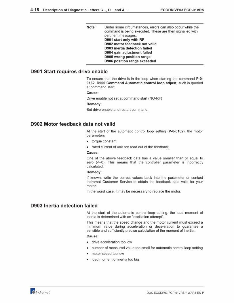
4-18 Description of Diagnostic Letters C..., D... and A... ECODRIVE03 FGP-01VRS
DOK-ECODR03-FGP-01VRS**-WAR1-EN-P
Note: Under some circumstances, errors can also occur while thecommand is being executed. These are then signalled withpertinent messages.
D901 start only with RF
D902 motor feedback not valid
D903 inertia detection failed
D904 gain adjustment failed
D905 wrong position range
D906 position range exceeded
D901 Start requires drive enable
To ensure that the drive is in the loop when starting the command P-0-
0162, D900 Command Automatic control loop adjust, such is queriedat command start.
Cause:
Drive enable not set at command start (NO-RF)
Remedy:
Set drive enable and restart command.
D902 Motor feedback data not valid
At the start of the automatic control loop setting (P-0-0162), the motorparameters
• torque constant
• rated current of unit are read out of the feedback.
Cause:
One of the above feedback data has a value smaller than or equal tozero (<=0). This means that the controller parameter is incorrectlycalculated.
Remedy:
If known, write the correct values back into the parameter or contactIndramat Customer Service to obtain the feedback data valid for yourmotor.
In the worst case, it may be necessary to replace the motor.
D903 Inertia detection failed
At the start of the automatic control loop setting, the load moment ofinertia is determined with an "oscillation attempt".
This means that the speed change and the motor current must exceed aminimum value during acceleration or deceleration to guarantee asensible and sufficiently precise calculation of the moment of inertia.
Cause:
• drive acceleration too low
• number of measured value too small for automatic control loop setting
• motor speed too low
• load moment of inertia too big

ECODRIVE03 FGP-01VRS Description of Diagnostic Letters C..., D... and A... 4-19
DOK-ECODR03-FGP-01VRS**-WAR1-EN-P
Remedy:
• increase bipolar torque/force value S-0-0092
• increase pos. accel S-0-0260
• increase pos. speed S-0-0259
• increase feedrate override S-0-0108
D904 Gain adjustment failed
In exceptional cases, difficulties in the automatic control loop setting mayarise. This means that an automatic setting is not possible. Standard ordefault values must therefore be loaded into the drive.
Cause:
• oscillating mechanical systems (resonance)
• high level of interference in the encoder signal
Remedy:
Satisfactory results can sometimes be achieved by starting the command
P-0-0162, D900 Command Automatic control loop adjust with a large
P-0-0163, Damping factor for autom. control loop adjust, i.e., lowdynamics.
This value can be reduced until the control loop behaves as needed.
If even then control loop settings remain unsuccessful, then the settingmust be manual.
Note: A manual setting should only be necessary in exceptionalcases!
D905 Position range invalid, P-0-0166 & P-0-0167
Before starting an automatic control loop setting, both travel range limits,i.e., upper and lower, must be defined.
When starting command P-0-0162, D900 Command Automatic control
loop adjust the number values are automatically checked for validity. Itis checked if the traversing path is large enough and if sensible valueshave been entered.
Possible fault causes:
• P-0-0167, Upper position limit for autom. control loop adjust
smaller than P-0-0166, Lower position limit for autom. control
loop adjustMaximum traversing path (= upper - lower limits) is lessthan 6 motor rotations and thus too small to start the automaticcontrol loop setting.
Remedy:
• clear command error by ending the command
• a) input new limits whereby:upper > lower limitsb) redefine limits to define a larger traversing range
• restart command with sensible traversing range

4-20 Description of Diagnostic Letters C..., D... and A... ECODRIVE03 FGP-01VRS
DOK-ECODR03-FGP-01VRS**-WAR1-EN-P
D906 Position range exceeded
During automatic control loop setting, there is a constant monitoring of
the valid traversing range P-0-0166 and P-0-0167.
Cause:
If only one of these limits is exceeded, then command error D906 isgenerated and the drive brought to standstill speed controlled.
Possible causes:
• actual position outside of defined traversing range
• limits redefined after command start
Remedy:
• clear command error and end command
• redefine limits so that the actual position is within defined traversingrange
• retart command using sensible traversing range
ECODRIVE03 FGP-01VRS Description of Diagnostic Letters C..., D... and A... 4-21
DOK-ECODR03-FGP-01VRS**-WAR1-EN-P
4.2 Status diagnostic messages
A002 Communication phase 2
For field bus and SERCOS devices, the control demands via the mastercommunication "communication phase 2", or the drive has been switched
to phase 2 by the command P-0-4023, C400 Communication phase 2
transition. Therefore, the drive is in the "parameter mode". In this mode,many parameters are editable, which can no more be edited in"communication phase 4" ("operation mode").
In this phase, usually
• for field bus and SERCOS devices, the communication parametersare transferred from the control to the drive and
• the functions Load and Save parameters ("file services“) areperformed when needed.
Before switching to communication phase 3 is possible, the command
S-0-0127, C100 Communication phase 3 transition check must bedone. In this command, the drive checks e.g. the validity of theparameters needed for the communication phase 3.
After successful execution of the command, the control switches thedrive to comm. phase 3 (with field bus and SERCOS devices), or thedrive switches by itself to phase 3 at the end of the command.
A003 Communication phase 3
For field bus and SERCOS devices, the control demands via the mastercommunication "communication phase 3", or the drive has been switched
to phase 3 by the command S-0-0127, C100 Communication phase 3
transition check. The drive is in the "restricted parameter mode". In thismode, still many parameters are editable too, which can no more beedited in "communication phase 4" ("operation mode").
Before switching to communication phase 4 is possible, the command
S-0-0128, C200 Communication phase 4 transition check must bedone. In this command, the drive checks e.g. the validity of theparameters needed for the communication phase 4 ("operation mode").
After successful execution of the command, the control switches thedrive to comm. phase 4 (with field bus and SERCOS devices), or thedrive switches by itself to phase 4 at the end of the command.
A010 Drive HALT
The feature Drive-Halt ( = contrary of Drive-Start) is activated by theapplied control via the used interface through clearing the /Drive-Halt bit(bit 13) in the master control word or by interrupting a drive controlcommand (i.e. drive-controlled homing).
The Drive-Halt feature is for decelerating the axis to standstill at defined
acceleration and defined jerk.
In process block mode, the acceleration and the jerk value of theprevious process block are active.
In Jog mode and in stepper position mode,
for acceleration, S-0-0260, Positioning acceleration is taken, and
for jerk, S-0-0193, Positioning jerk is taken.
In Velocity control and in Torque control mode, the drive is deceleratedto standstill by setting the velocity command to 0 and with the max.torque.
4-22 Description of Diagnostic Letters C..., D... and A... ECODRIVE03 FGP-01VRS
DOK-ECODR03-FGP-01VRS**-WAR1-EN-P
A012 Control and power sections ready for operation
The drive is supplied with control voltage, and the power is switched on.The drive is ready to deliver power.
A013 Ready for power on
The drive is supplied with a control voltage, and there are no errors in thedrive controller. The drive is ready to be turned on with power.
A100 Drive in TORQUE control
The drive is in the torque control operating mode. It follows the torquecommand value sequence which was set by the control system.
A101 Drive in VELOCITY control
The drive is in the velocity control operating mode. It follows the velocitycommand value sequence set by the control system. The velocity controlloop is closed in the drive.
A102 Position mode with encoder 1
The drive is in position control mode. The position loop is closed in thedrive by a position encoder. The control system only sets the positioncommand value sequence; the drive follows the command value with a
systematical lag (following error).
Encoder 1 indicates that the position encoder is installed on the motorshaft (indirect measurement of the axis position).
A103 Position mode with encoder 2
The drive is in position control mode. The position loop is closed in thedrive by a position encoder. The control system only sets the positioncommand value sequence; the drive follows the command value with a
systematical lag (following error).
Encoder 2 indicates that the position encoder is installed on the machineaxis (direct axis position measurement).
A104 Position mode lagless, encoder 1
The drive is in position control mode. The position loop is closed in thedrive by a position encoder. The control system only sets the position
command value sequence; the drive follows the command value without
following (lag) error.
Encoder 1 indicates that the position encoder is installed on the motorshaft (indirect measurement of axis position).

ECODRIVE03 FGP-01VRS Description of Diagnostic Letters C..., D... and A... 4-23
DOK-ECODR03-FGP-01VRS**-WAR1-EN-P
A105 Position control lagless, feedback 2
The drive is in position control mode. The position loop is closed in thedrive by a position encoder. The control system only sets the position
command value sequence; the drive follows the command value without
following (lag) error.
Encoder 2 indicates that the position encoder is installed on the machineaxis (direct axis position measurement).
A106 Drive controlled interpolation, encoder 1
The drive receives a position command value from the control system
which is identical to the target position of the travel path. Then the drive
generates (interpolates) an internal position command value sequence,which uses the control system to maintain maximum values for jerk,velocity and acceleration sequences.
The drive moves with a systematical lag (following error) to the targetposition.
Encoder 1 indicates that the position encoder is installed on the motorshaft (indirect measurement of the axis position).
A107 Drive controlled interpolation, encoder 2
The drive receives a position command value from the control system
which is identical to the target position of the travel path. Then the drive
generates (interpolates) an internal position command value sequence,which uses the control system to maintain maximum values for jerk,velocity and acceleration sequences.
The drive moves with a systematical lag (following error) to the targetposition.
Encoder 2 indicates that the position encoder is installed on the machineaxis (direct axis position measurement).
A108 Drive controlled interpolation, lagless, encoder 1
The drive receives a position command value from the control system
which is identical to the target position of the travel path. Then the drive
generates (interpolates) an internal position command value sequence,which uses the control system to maintain maximum values for jerk,velocity and acceleration sequences.
The drive moves without following error to the target position.
Encoder 1 indicates that the position encoder is installed on the motorshaft (indirect measurement of the axis position).
A109 Drive controlled interpolation, lagless, encoder 2
The drive receives a position command value from the control system
which is identical to the target position of the travel path. Then the drive
generates (interpolates) an internal position command value sequence,which uses the control system to maintain maximum values for jerk,velocity and acceleration sequences.
The drive moves without following error to the target position.
Encoder 2 indicates that the position encoder is installed on the machineaxis (direct axis position measurement).
4-24 Description of Diagnostic Letters C..., D... and A... ECODRIVE03 FGP-01VRS
DOK-ECODR03-FGP-01VRS**-WAR1-EN-P
A146 Relative drive controlled interpolation, encoder 1
In the S-0-0282, Travel distance parameter, the drive receives a
distance specification from the controller. When bit 0 of the S-0-0346,
Setup flag for relative command values parameter is toggled, this
distance is summed up to the value in S-0-0258, Target position. Inorder to get from the current position to the new target position, the drivenow generates (interpolates) an internal position command value curve.This is done taking the limit values of velocity, acceleration, and jerk inthe parameters
• S-0-0259, Positioning velocity
• S-0-0260, Positioning acceleration
• S-0-0193, Positioning jerk
into account.
The drive approaches the target position with a position lag that isproportional to the velocity.
Encoder 1 means that the position encoder is attached to the motorshaft (indirect measurement of the axis position).
A147 Relative drive controlled interpolation, encoder 2
In the S-0-0282, Travel distance parameter, the drive receives a
distance specification from the controller. When bit 0 of the S-0-0346,
Setup flag for relative command values parameter is toggled, this
distance is summed up to the value in S-0-0258, Target position. Inorder to get from the current position to the new target position, the drivenow generates (interpolates) an internal position command value curve.This is done taking the limit values of velocity, acceleration, and jerk inthe parameters
• S-0-0259, Positioning velocity
• S-0-0260, Positioning acceleration
• S-0-0193, Positioning jerk
into account.
The drive approaches the target position with a position lag that isproportional to the velocity.
Encoder 2 means that the position encoder that is attached to the load isused for closing the position control loop (direct axis positionmeasurement).
A148 Relative drive contr. interpolation, enc. 1, lagless
In the S-0-0282, Travel distance parameter, the drive receives a
distance specification from the controller. When bit 0 of the S-0-0346,
Setup flag for relative command values parameter is toggled, this
distance is summed up to the value in S-0-0258, Target position. Inorder to get from the current position to the new target position, the drivenow generates (interpolates) an internal position command value curve.This is done taking the limit values of velocity, acceleration, and jerk inthe parameters
• S-0-0259, Positioning velocity
• S-0-0260, Positioning acceleration
• S-0-0193, Positioning jerk
into account.
The drive approaches the target position of the travel path without a
position lag. Encoder 1 means that the position encoder is attached tothe motor shaft (indirect measurement of the axis position).

ECODRIVE03 FGP-01VRS Description of Diagnostic Letters C..., D... and A... 4-25
DOK-ECODR03-FGP-01VRS**-WAR1-EN-P
A149 Relative drive contr. interpolation, enc. 2, lagless
In the S-0-0282, Travel distance parameter, the drive receives a
distance specification from the controller. When bit 0 of the S-0-0346,
Setup flag for relative command values parameter is toggled, this
distance is summed up to the value in S-0-0258, Target position. Inorder to get from the current position to the new target position, the drivenow generates (interpolates) an internal position command value curve.This is done taking the limit values of velocity, acceleration, and jerk inthe parameters
• S-0-0259, Positioning velocity
• S-0-0260, Positioning acceleration
• S-0-0193, Positioning jerk
into account.
The drive approaches the target position of the travel path without aposition lag.
Encoder 2 means that the position encoder that is attached to the load isused for closing the position control loop (direct axis positionmeasurement).
A206 Process block mode, encoder 1
The drive performs a closed loop position control with systematical lag.The actual value comes from the encoder 1 (motor encoder). Thecommand value profile is generated in the drive.
Target position, velocity, acceleration and jerk are determined by a pre-
programmed process block. Depending on P-0-4019, Process block
mode, the target position is interpreted as an absolute value or as arelative distance to move.
A207 Process block mode lagless, encoder 1
The drive performs a closed loop position control without lag. The actualvalue comes from the encoder 1 (motor encoder). The command valueprofile is generated in the drive.
Target position, velocity, acceleration and jerk are determined by a pre-
programmed process block. Depending on P-0-4019, Process block
mode, the target position is interpreted as an absolute value or as arelative distance to move.
A208 JOG mode positive
The drive moves with a jogging velocity (P-0-4030) in the positivedirection. The motor is turning clockwise, when viewing the motor shaft.
A210 Process block mode, encoder 2
The drive performs a closed loop position control with systematical lag.The actual value comes from the encoder 2 (ext. encoder). Thecommand value profile is generated in the drive.
Target position, velocity, acceleration and jerk are determined by a pre-
programmed process block. Depending on P-0-4019, Process block
mode, the target position is interpreted as an absolute value or as arelative distance to move.

4-26 Description of Diagnostic Letters C..., D... and A... ECODRIVE03 FGP-01VRS
DOK-ECODR03-FGP-01VRS**-WAR1-EN-P
A211 Process block mode lagless, encoder 2
The drive performs a closed loop position control without lag. The actualvalue comes from the encoder 2 (ext. encoder). The command valueprofile is generated in the drive.
Target position, velocity, acceleration and jerk are determined by a pre-
programmed process block. Depending on P-0-4019, Process block
mode, the target position is interpreted as an absolute value or as arelative distance to move.
A218 JOG mode negative
The drive moves with a jogging velocity (P-0-4030) in the negativedirection. The motor is turning counter clockwise, when viewing themotor shaft.
A800 Unknown operation mode
There is no diagnosis for the activated operation mode.

ECODRIVE03 FGP-01VRS Description of Diagnostic Letters C..., D... and A... 4-27
DOK-ECODR03-FGP-01VRS**-WAR1-EN-P
4.3 Diagnostic messages for basic initialization and after
fatal System errors
Diagnostic Message Display: -0
The writable data storage of the drive controller is tested for itsfunctional capability.
If an error is detected, this display will remain.
Diagnostic Message Display: -1
The hardware of the amplifier is beig initialized.
Diagnostic Message Display: -2
Cause:
The control supply voltage of the encoder is missing.
Remedy:
Exchange the hardware.
Diagnostic Message Display: -3
Initializing the parameters from the NovRam and calculating therespective data depending from the parameter contents.
Diagnostic Message Display: -4
Initializing and checking the command communication.
Diagnostic Message Display: -5
Initializing the system control.
Diagnostic Message Display: -6
Starting the system control.
Diagnostic Message Display: E1
Cause:
Processor fault, caused by static discharge, program error or hardwarefault. More information is available via a terminal connected to the RS-232 interface.
Remedy:
Switch the amplifier off and on again; if the fault is still present, exchangethe hardware. In any case inform the customer service.

4-28 Description of Diagnostic Letters C..., D... and A... ECODRIVE03 FGP-01VRS
DOK-ECODR03-FGP-01VRS**-WAR1-EN-P
Diagnostic Message Display: E2
Cause:
Test of the RAM on the programming module has shown an error. RAMdefective or not plugged properly.
Remedy:
Switch off, check the plug connection and switch on again; if the errorhappens agains, exchange the firmware module.
Diagnostic Message Display: E3
Cause:
Caused by a hardware fault or by a static discharge, the 1st
watchdog ofthe amplifier has triggered.
Remedy:
Switch the amplifier off and on again; if E3 appears again, exchange theamplifier. In any case inform the customer service. Please explain theexact circumstances under which the error occurred.
Diagnostic Message Display: E4
Cause:
Caused by a hardware fault or by a static discharge, the 2nd
watchdog ofthe amplifier has triggered.
Remedy:
Switch the amplifier off and on again; if E4 appears again, exchange theamplifier. In any case inform the customer service.
Diagnostic Message Display: E5
Cause:
Test of the dual-port-RAM for command communication failed. Maybethe hardware for command communication is not plugged on properly.
Remedy:
Check the plug connection; if OK, exchange the amplifier.
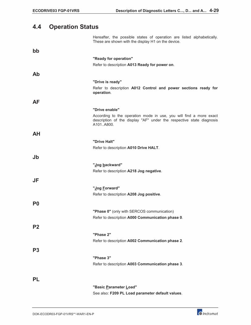
ECODRIVE03 FGP-01VRS Description of Diagnostic Letters C..., D... and A... 4-29
DOK-ECODR03-FGP-01VRS**-WAR1-EN-P
4.4 Operation Status
Hereafter, the possible states of operation are listed alphabetically.These are shown with the display H1 on the device.
bb
"Ready for operation"
Refer to description A013 Ready for power on.
Ab
"Drive is ready"
Refer to description A012 Control and power sections ready for
operation.
AF
"Drive enable"
According to the operation mode in use, you will find a more exactdescription of the display "AF" under the respective state diagnosisA101..A800.
AH
"Drive Halt"
Refer to description A010 Drive HALT.
Jb
"Jog backward"
Refer to description A218 Jog negative.
JF
"Jog Forward"
Refer to description A208 Jog positive.
P0
"Phase 0" (only with SERCOS communication)
Refer to description A000 Communication phase 0.
P2
"Phase 2"
Refer to description A002 Communication phase 2.
P3
"Phase 3"
Refer to description A003 Communication phase 3.
PL
"Basic Parameter Load"
See also: F209 PL Load parameter default values.

4-30 Description of Diagnostic Letters C..., D... and A... ECODRIVE03 FGP-01VRS
DOK-ECODR03-FGP-01VRS**-WAR1-EN-P
UL
"Basic Load"
See also: F208 UL The motor type has changed.