3 control-of-pm1
63
Control of Particulate Matter Dr. Wesam Al Madhoun
-
Upload
candy-dreamgirl -
Category
Documents
-
view
98 -
download
0
Transcript of 3 control-of-pm1
Control of Particulate Matter
Dr. Wesam Al Madhoun
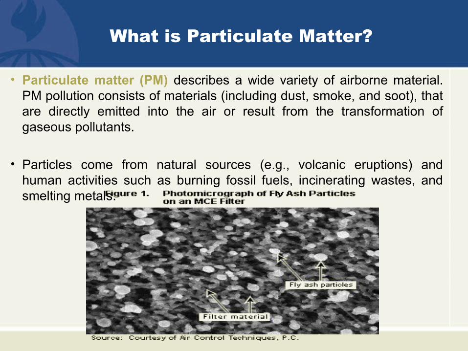
What is Particulate Matter?
• Particulate matter (PM) describes a wide variety of airborne material. PM pollution consists of materials (including dust, smoke, and soot), that are directly emitted into the air or result from the transformation of gaseous pollutants.
• Particles come from natural sources (e.g., volcanic eruptions) and human activities such as burning fossil fuels, incinerating wastes, and smelting metals.
Characteristics of Particles
• The most important characteristic of particulate matter (PM) is the particle size.
• This property has the greatest impact on the behavior of particulate matter in control equipment, the atmosphere, and the respiratory tract.
• Particles of importance in air pollution control span a broad size range from extremely small (0.01 micrometer) to more than 1,000 micrometers.
• As a frame of reference, a human hair has a diameter of approximately 50 micrometers.
• The chemical composition of the particulate matter is also important.
• Absorption and heterogeneous nucleation of vapor phase pollutants onto existing particles can create toxic particulate matter.
• Other characteristics besides size and chemical composition should be considered when selecting an appropriate particulate control device for a gas stream.
• Other important characteristics of particulate matter in gas streams include stickiness and explosiveness.
Formation Mechanisms
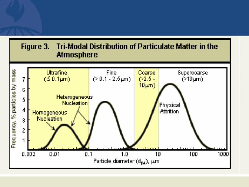
• Physical attrition occurs when two surfaces rub together.
• The composition and density of the particles formed are identical to the parent material and range in size from less than 10 micrometers to almost 1,000 micrometers.
• Combustion particle burnout occurs when fuel particles are injected into the hot furnace area of a combustion process.
• as the combustion progresses, are reduced to ash and char particles that are primarily in the 1- to 100-micrometer size range.
• Homogeneous nucleation and heterogeneous nucleation
involve the conversion of vapor phase materials to a
particulate form.
• Homogeneous and heterogeneous nucleation generally create
particles that are very small, often between 0.1 and 1.0
micrometer.
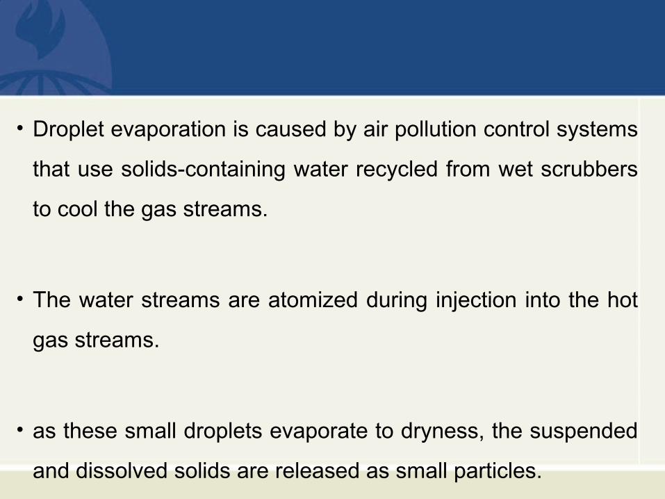
• Droplet evaporation is caused by air pollution control systems
that use solids-containing water recycled from wet scrubbers
to cool the gas streams.
• The water streams are atomized during injection into the hot
gas streams.
• as these small droplets evaporate to dryness, the suspended
and dissolved solids are released as small particles.
Control Techniques
• Gravity settling chamber
• Mechanical collectors
• Particulate wet scrubbers
• Electrostatic precipitators
• Fabric filters
Gravity Settling Chambers
• This category of control devices relies upon gravity settling to remove particles from the gas stream.
• Gravity settling chambers are used only for very large particles in the upper end of the supercoarse size range (approximately 75 micrometers and larger).
• The very low terminal settling velocities of most particles encountered in the field of air pollution limit the usefulness of gravity settling chambers.
• The stringent control requirements adopted in the late 1960s through early 1970s have resulted in a sharp decline in the use of this type of collector.
Mechanical Collectors
• The particulate-laden gas stream is forced to spin in a
cyclonic manner.
• The mass of the particles causes them to move toward the
outside of the vortex.
• Most of the large-diameter particles enter a hopper below the
cyclonic tubes while the gas stream turns and exits the tube.
• There are two main types of mechanical collectors: (1) large-diameter cyclones, and (2) small-diameter multi-cyclones.
• Large-diameter cyclones are usually one to six feet in diameter; while small-diameter multi-cyclones usually have diameters between 3 and 12 inches.
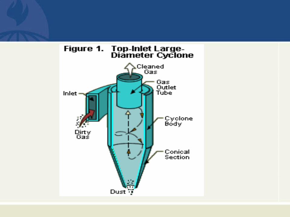
• A typical large-diameter cyclone system is shown in Figure 1.
• The gas stream enters the cyclone tangentially and creates a weak vortex of spinning gas in the cyclone body.
• Large-diameter particles move toward the cyclone body wall
and then settle into the hopper of the cyclone.
• The cleaned gas turns and exits the cyclone.
• Large-diameter cyclones are used to collect particles down to
1/16 inch (1.5 mm) diameter and above.
• In systems where the large-diameter cyclone is located after the fan (positive pressure), the treated gas is usually discharged directly from the cyclone.
• In systems where the cyclone is located before the fan (negative pressure), the gas stream is either exhausted from a separate stack or from the discharge of the fan itself.
• In negative pressure systems, a solids discharge valve is used to prevent air infiltration up through the hopper area.
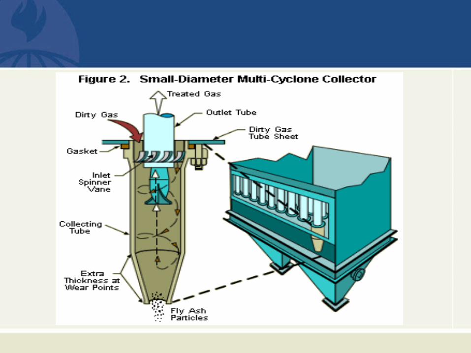
• A small-diameter cyclone tube is shown in Figure 2.
• Vanes located on the inlet of each of the tubes create the spinning movement of the gas stream.
• Most of the commercial tubes are six, nine, or twelve inches in diameter.
• Due to the limited gas handling capacity of each tube, large numbers of tubes are mounted in parallel in a single collector.
• The small-diameter of the cyclone tube creates more rapid spinning
of the gas stream than in large-diameter cyclones.
• The particles moving outward in the spinning gas stream have a
relatively shorter distance to travel in a small-diameter multi-cyclone
tube before they reach the cyclone body wall.
• These features allow small-diameter multi-cyclones to collect
considerably smaller particles than large-diameter cyclones can.
• Small-diameter multi-cyclones, such as the one shown in Figure 2
are capable of removing particles having diameters down to 5
micrometers.
• Small-diameter multi-cyclones are not generally used for very large
diameter material, such as 3 mm and above, because large
particles may plug the spinner vanes in the multi-cyclone tubes.
• Some mechanical collectors are specially designed to provide high-
efficiency PM collection down to a particle size of one micrometer.
• These have higher gas velocities within the cyclone tubes and
different cyclone geometries than those shown in Figure 2.
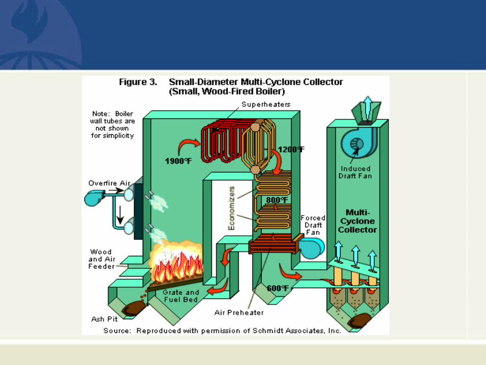
• A typical application of a conventional multi-cyclone collector is
shown in Figure 3.
• In this example, the multi-cyclone is located after a small, wood-
fired boiler and is used as a pre-collector for the fabric filter.
• Mechanical collectors are used whenever the particle size relatively large (> 5 micrometers) and/or the control efficiency requirements are in the low-to-moderate range of 50 to 90%.
• They are also used as the pre-collector of large-diameter embers generated in some combustion systems.
• Removal of the embers is necessary to protect high-efficiency particulate control systems downstream from the mechanical collectors.
• Most mechanical collectors are not applicable to industrial sources that generate sticky and/or wet particulate matter.
• These materials can accumulate on the cyclone body wall or the inlet spinner vanes of conventional multi-cyclone collectors.
Particulate Wet Scrubbers
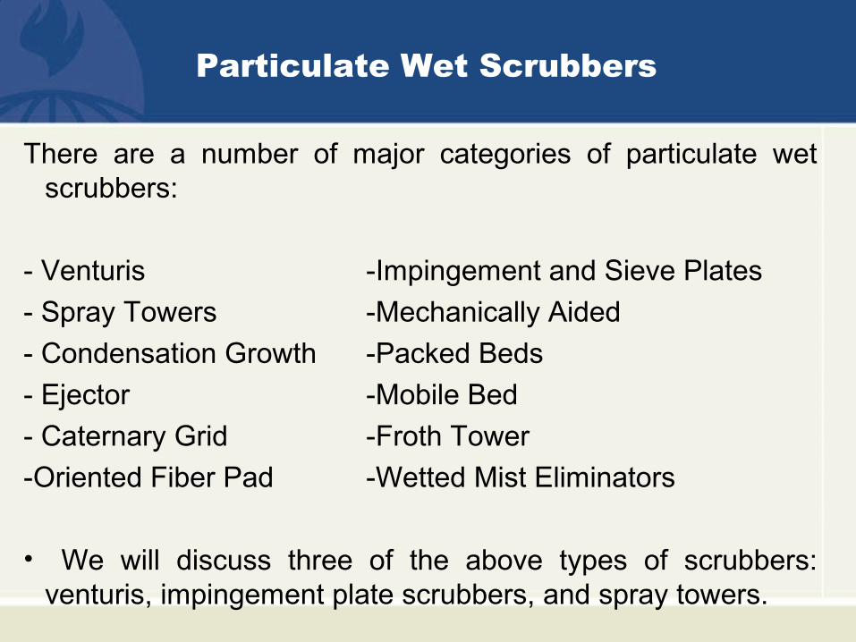
There are a number of major categories of particulate wet scrubbers:
- Venturis -Impingement and Sieve Plates
- Spray Towers -Mechanically Aided
- Condensation Growth -Packed Beds
- Ejector -Mobile Bed
- Caternary Grid -Froth Tower
-Oriented Fiber Pad -Wetted Mist Eliminators
• We will discuss three of the above types of scrubbers: venturis, impingement plate scrubbers, and spray towers.
Venturi Scrubbers
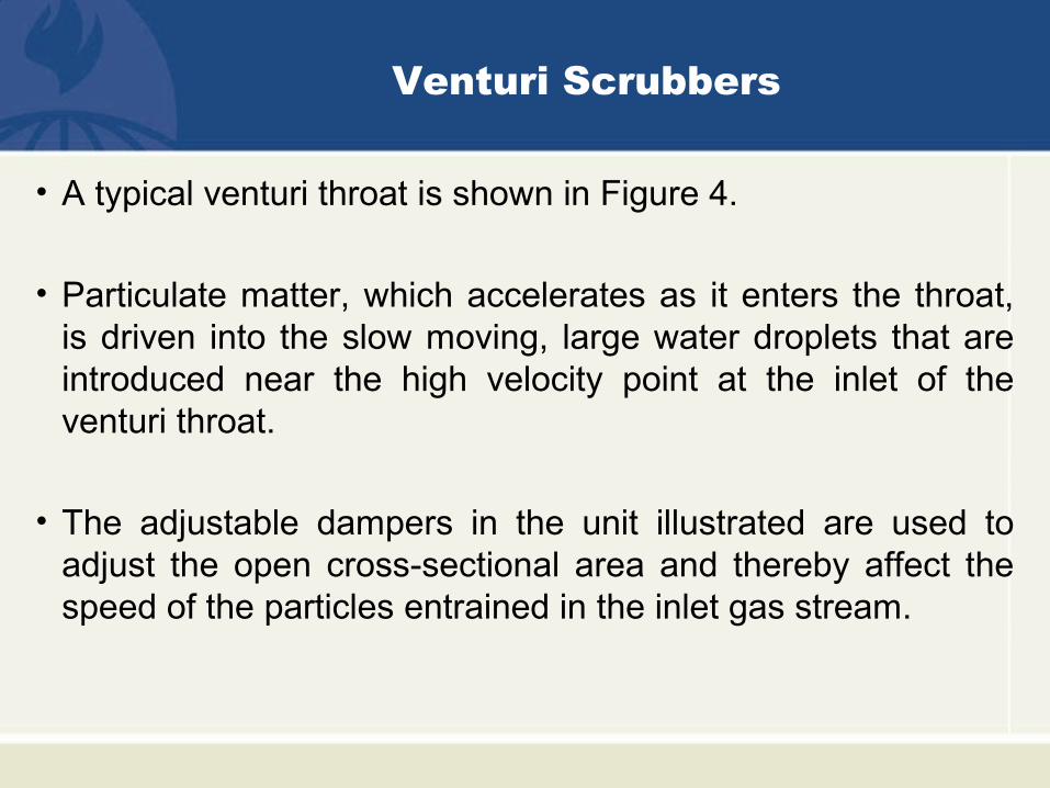
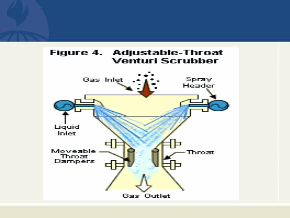
• A typical venturi throat is shown in Figure 4.
• Particulate matter, which accelerates as it enters the throat, is driven into the slow moving, large water droplets that are introduced near the high velocity point at the inlet of the venturi throat.
• The adjustable dampers in the unit illustrated are used to adjust the open cross-sectional area and thereby affect the speed of the particles entrained in the inlet gas stream.
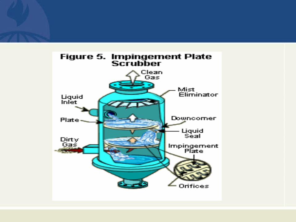
Impingement Plate Scrubbers
• An impingement plate scrubber is shown in Figure 5.
• These scrubbers usually have one to three horizontal plates, each of which has a large number of small holes.
• The gas stream accelerating through the holes atomizes some water droplets in the water layer above the plate.
• Particles impact into these water droplets.
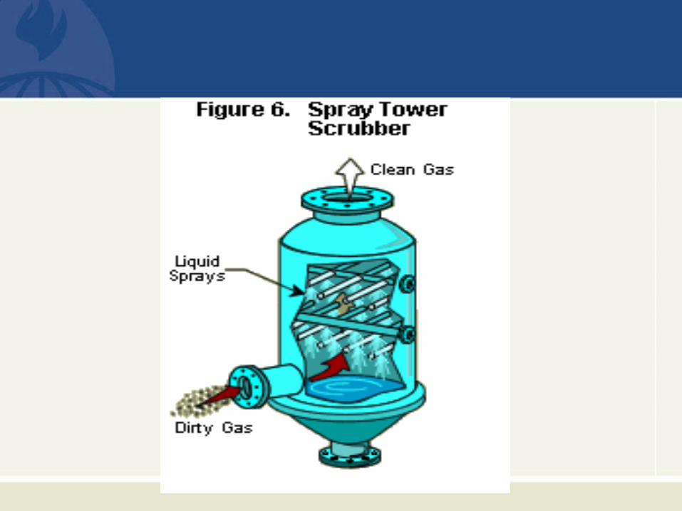
Spray Tower Scrubbers
• A typical spray tower scrubber is shown in Figure 6.
• This is the simplest type of particulate wet scrubber in
commercial service.
• Sets of spray nozzles located near the top of the scrubber
vessel generate water droplets that impact with particles in
the gas stream as the gas stream moves upwards.
• Each of the categories of particulate wet scrubbers listed earlier has a large number of different design types.
• For example, venturi scrubbers include the following different design types: (1) fixed throat, (2) adjustable throat.
• Spray tower scrubbers include these design types: (1) open, (2) cyclonic.
• The scrubber categories listed above comprise more than fifty different types of scrubbers in common commercial use.
• Scrubbers are by far the most diverse group of air pollution control devices used for particulate control.
Wet Scrubbing Systems
• Each particulate wet scrubber vessel is part of a large, and sometimes complex, wet scrubbing system.
• For example, Figure 7 illustrates a venturi scrubber in a scrubbing system.
• The evaporative cooler, located before the venturi scrubber in the system, cools the gas stream, which serves the following purpose:
1- It protects the construction materials of the venturi throat.
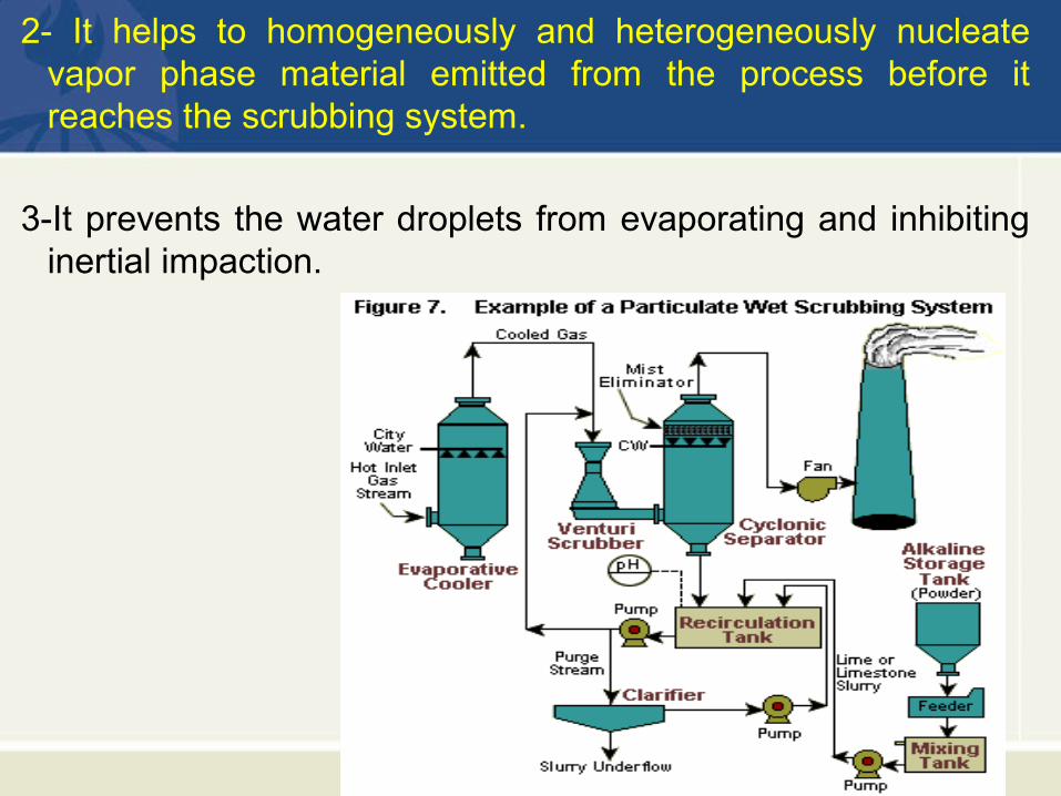
2- It helps to homogeneously and heterogeneously nucleate vapor phase material emitted from the process before it reaches the scrubbing system.
3-It prevents the water droplets from evaporating and inhibiting inertial impaction.
• Located after the venturi scrubber, the cyclonic separator removes entrained water droplets from the gas stream leaving the venturi.
• The cyclonic separator consists of a cyclonic vessel and a horizontal mist eliminator.
• The overall scrubbing system includes pumps for liquid recirculation, a tank to treat the liquid being recirculated, an alkali addition unit to control the liquid pH, a purged liquid treatment unit, a fan for gas movement, and a stack.
• There are a wide variety of wet scrubber system designs; however, these components are present in many systems, regardless of which type of particulate matter scrubber is used.
The ability of a particulate wet scrubber to remove particles
depends on two or more of the following variables:
• The size (aerodynamic diameter) of the particle
• The velocity of the particle
• The velocity of the droplet.
Scrubber Operating Principles
Collection Efficiency of Wet Scrubbers
• The velocities of the particle-laden gas stream and the liquid
targets vary substantially.
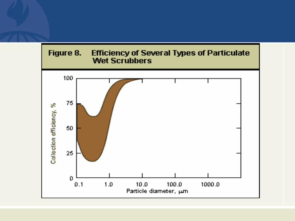
• There are substantial differences in the ability of particulate
wet scrubbers to collect particles less than approximately 5
micrometers.
• This is illustrated in Figure 8.
• If a significant portion of the particulate matter mass is composed of particles < 5 micrometers, care is needed to select the type of scrubber that is effective in this size range.
• It should be noted that some types of wet scrubbers have limited capability to remove particles in the less than 0.3-micrometer range.
• These particles are so small that their movement is influenced by collisions with individual molecules in the gas stream.
Advantages and Disadvantages of Scrubbers
• Many types of particulate wet scrubbers can provide high efficiency control of particulate matter.
• One of the main advantages of particulate wet scrubbers is that they are often able to simultaneously collect particulate matter and gaseous pollutants.
• Also, wet scrubbers can often be used on sources that have potentially explosive gases or particulate matter.
• They are compact and can often be retrofitted into existing plants with very limited space.
• One of the main disadvantages of particulate wet scrubbers
is that they require make-up water to replace the water
vaporized into the gas stream and lost to purge liquid and
sludge removed from the scrubber system.
• Wet scrubbers generate a waste stream that must be
treated properly.
Electrostatic Precipitators
• An electrostatic precipitator (ESP) uses non-uniform, high-voltage fields to apply large electrical charges to particles moving through the field.
• The charged particles move toward an oppositely charged collection surface, where they accumulate.
• There are three main styles of electrostatic precipitators:
(1) negatively charged dry precipitators, (2) negatively
charged wetted-wall precipitators, and (3) positively charged
two-stage precipitators.
• The negatively charged dry precipitators are the type most frequently used on large applications such as coal-fired boilers, cement kilns, and kraft pulp mills.
• Wetted-wall precipitators (wet precipitators) are often used to collect mist and/or solid material that is moderately sticky.
• The positively charged two-stage precipitators are used only for the removal of mists.
• The discussions will focus only on negatively charged dry precipitators because these are the most common types of precipitators.
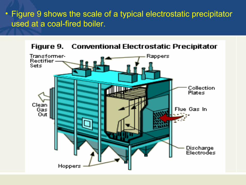
• Figure 9 shows the scale of a typical electrostatic precipitator used at a coal-fired boiler.
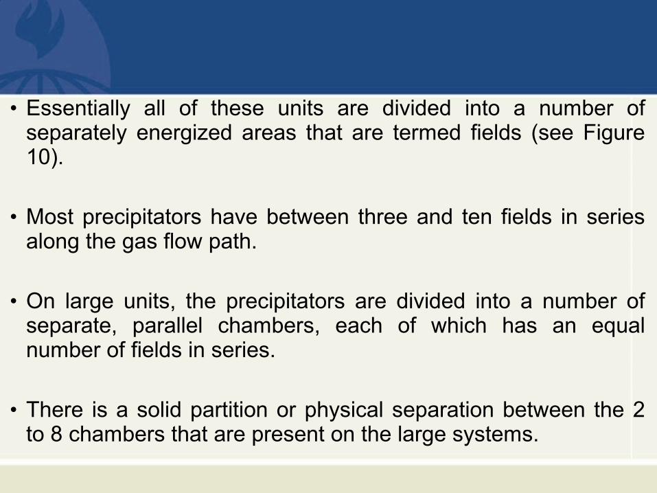
• Essentially all of these units are divided into a number of separately energized areas that are termed fields (see Figure 10).
• Most precipitators have between three and ten fields in series along the gas flow path.
• On large units, the precipitators are divided into a number of separate, parallel chambers, each of which has an equal number of fields in series.
• There is a solid partition or physical separation between the 2 to 8 chambers that are present on the large systems.
Advantages and Disadvantages of ESPs
• Electrostatic precipitators can have very high efficiencies due to the strong electrical forces applied to the small particles.
• These types of collectors can be used when the gas stream is not explosive and does not contain entrained droplets or other sticky material.
• The composition of the particulate matter is very important because it influences the electrical conductivity within the dust layers on the collection plate.
• Resistivity, an important concept associated with electrostatic precipitators, is a measure of the ability of the particulate matter to conduct electricity and is expressed in units of ohm-cm.
• As the resistivity increases, the ability of the particulate matter to conduct electricity decreases.
• Precipitators can be designed to work in any resistivity range; however, they usually work best when the resistivity is in the moderate range (108 to 1010 ohms-cm).
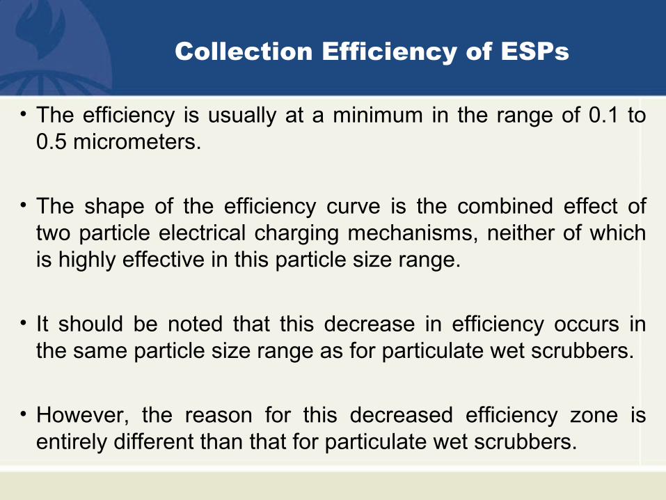
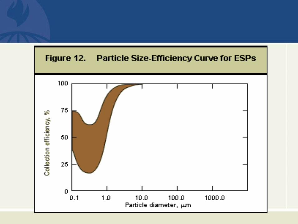
Collection Efficiency of ESPs
• The efficiency is usually at a minimum in the range of 0.1 to 0.5 micrometers.
• The shape of the efficiency curve is the combined effect of two particle electrical charging mechanisms, neither of which is highly effective in this particle size range.
• It should be noted that this decrease in efficiency occurs in the same particle size range as for particulate wet scrubbers.
• However, the reason for this decreased efficiency zone is entirely different than that for particulate wet scrubbers.
Fabric Filters
Operating Principles • Fabric filters collect particulate matter on the surfaces of filter
bags.
• Most of the particles are captured by inertial impaction, interception, Brownian diffusion, and sieving on already collected particles that have formed a dust layer on the bags.
• The fabric material itself can capture particles that have penetrated through the dust layers.
• Electrostatic attraction may also contribute to particle capture in the dust layer and in the fabric itself.
• Due to the multiple mechanisms of particle capture possible, fabric filters can be highly efficient for the entire particle size range of interest in air pollution control.
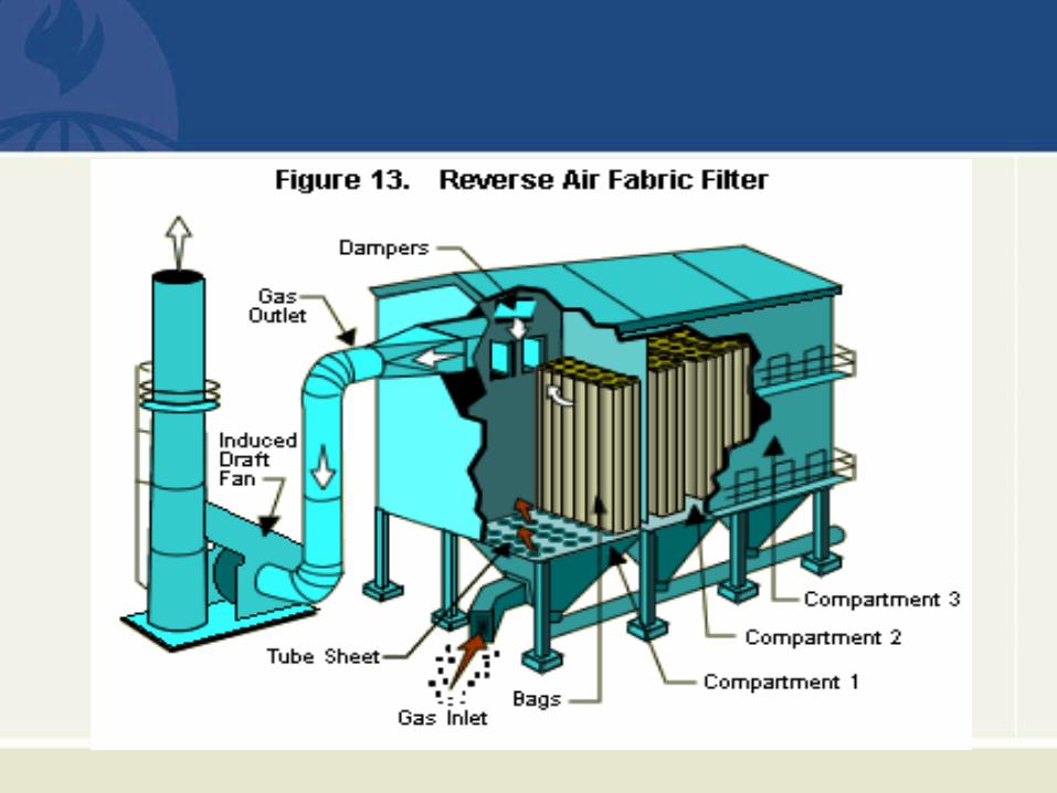
Types of Fabric Filters• A reverse-air-type fabric filter, shown in Figure 13, is one of the
major categories of fabric filters. It is used mainly for large industrial sources.
• In this type, the particle-laden gas stream enters from the bottom and passes into the inside of the bags.
• The dust cake accumulates on the inside surfaces of the bags.
• Filtered gas passes through the bags and is exhausted from the unit.
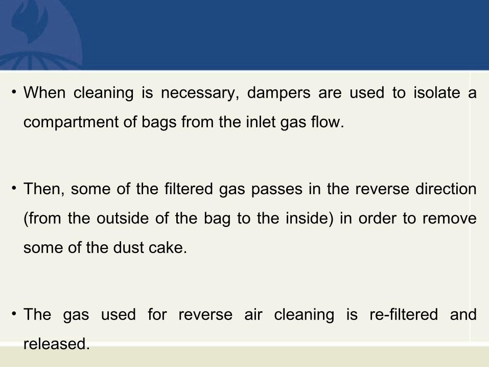
• When cleaning is necessary, dampers are used to isolate a
compartment of bags from the inlet gas flow.
• Then, some of the filtered gas passes in the reverse direction
(from the outside of the bag to the inside) in order to remove
some of the dust cake.
• The gas used for reverse air cleaning is re-filtered and
released.
• Another common type of fabric filter is the pulse jet shown in Figure 14.
• In this type, the bags are supported on metal wire cages that are suspended from the top of the unit.
• Particulate-laden gas flows around the outside of the bags, and a dust cake accumulates on the exterior surfaces.
• When cleaning is needed, a very-short-duration pulse of compressed air is injected at the top inside part of each bag in the row of bags being cleaned.
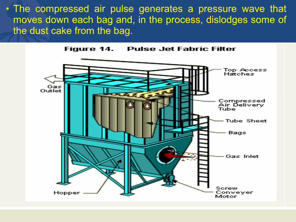
• The compressed air pulse generates a pressure wave that moves down each bag and, in the process, dislodges some of the dust cake from the bag.
Advantages and Disadvantages of Fabric Filters
• Fabric filters are used in a wide variety of applications where
high efficiency particulate collection is needed.
• The control efficiencies usually range from 99% to greater
than 99.5% depending on the characteristics of the particulate
matter and the fabric filter design.
• Fabric filters can be very efficient at collecting particles in the
entire size range of interest in air pollution control.
• The performance of fabric filters is usually independent of the chemical composition of the particulate matter.
• They are not used when the gas stream generated by the process equipment includes corrosive materials that could chemically attack the filter media.
• Fabric filters are also not used when there are sticky or wet particles in the gas stream.
• These materials accumulate on the filter media surface and block gas movement.
• Fabric filters must be designed carefully if there are
potentially combustible or explosive particulate matter, gases,
or vapors in the gas stream being treated.
• If these conditions are severe, alternative control techniques,
such as wet scrubbers, are often used.
General Applicability of Particulate Control Systems
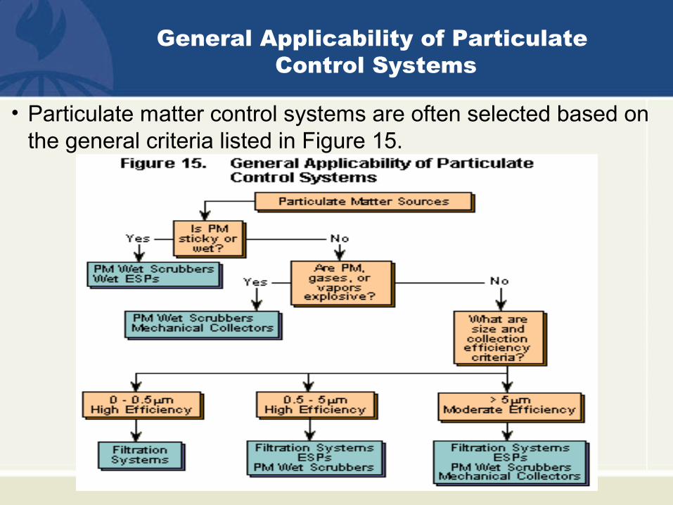
• Particulate matter control systems are often selected based on the general criteria listed in Figure 15.
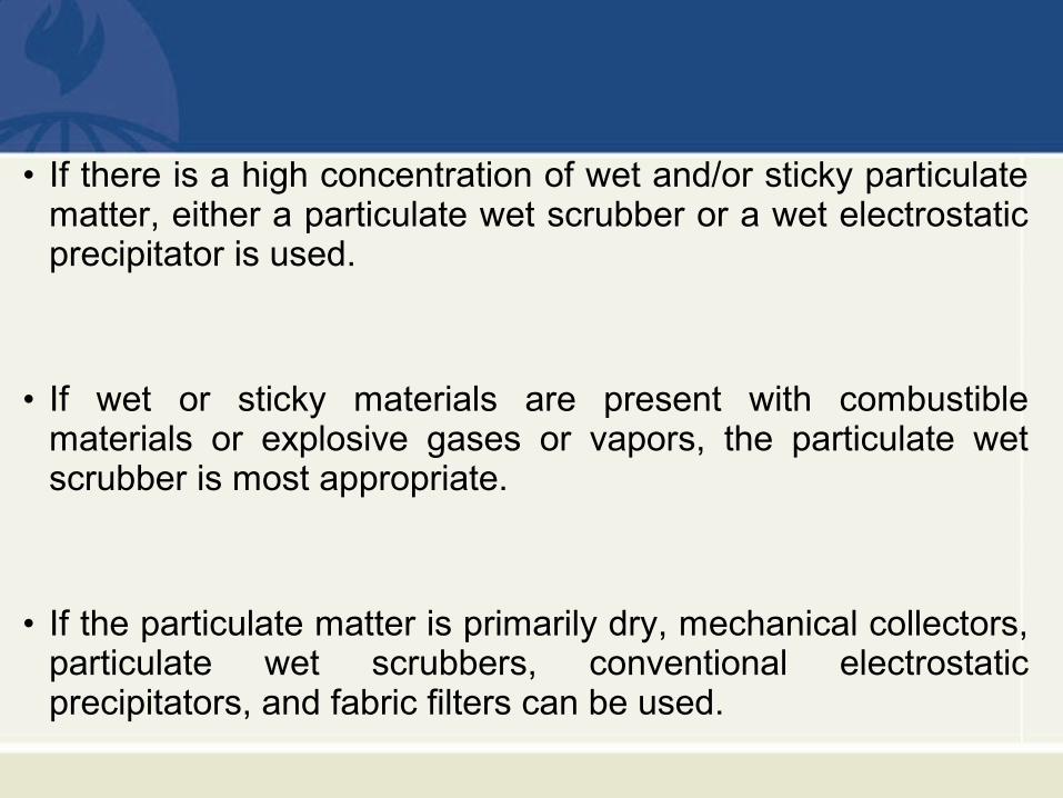
• If there is a high concentration of wet and/or sticky particulate matter, either a particulate wet scrubber or a wet electrostatic precipitator is used.
• If wet or sticky materials are present with combustible materials or explosive gases or vapors, the particulate wet scrubber is most appropriate.
• If the particulate matter is primarily dry, mechanical collectors, particulate wet scrubbers, conventional electrostatic precipitators, and fabric filters can be used.
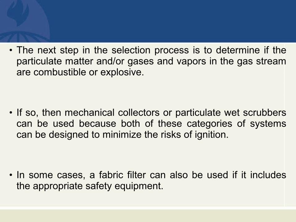
• The next step in the selection process is to determine if the particulate matter and/or gases and vapors in the gas stream are combustible or explosive.
• If so, then mechanical collectors or particulate wet scrubbers can be used because both of these categories of systems can be designed to minimize the risks of ignition.
• In some cases, a fabric filter can also be used if it includes the appropriate safety equipment.
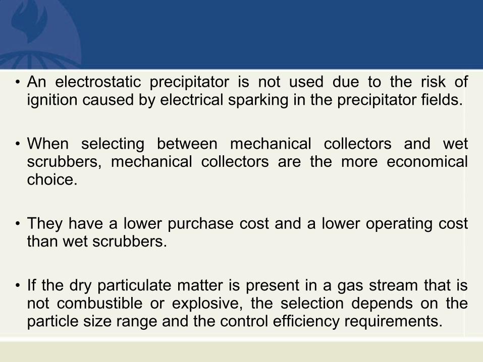
• An electrostatic precipitator is not used due to the risk of ignition caused by electrical sparking in the precipitator fields.
• When selecting between mechanical collectors and wet scrubbers, mechanical collectors are the more economical choice.
• They have a lower purchase cost and a lower operating cost than wet scrubbers.
• If the dry particulate matter is present in a gas stream that is not combustible or explosive, the selection depends on the particle size range and the control efficiency requirements.
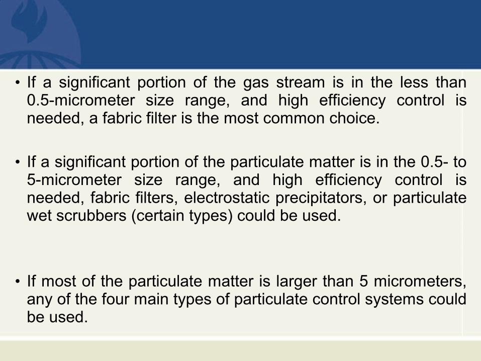
• If a significant portion of the gas stream is in the less than 0.5-micrometer size range, and high efficiency control is needed, a fabric filter is the most common choice.
• If a significant portion of the particulate matter is in the 0.5- to 5-micrometer size range, and high efficiency control is needed, fabric filters, electrostatic precipitators, or particulate wet scrubbers (certain types) could be used.
• If most of the particulate matter is larger than 5 micrometers, any of the four main types of particulate control systems could be used.
• There are numerous exceptions to the general applicability
information presented above due to site-specific process
conditions and unique particulate matter control systems.
• Nevertheless, this chart provides a general indication of the
uses and limitations of many commercially available
particulate matter control systems.


![3 PM1 - saintlouiswaremme.be · 3 PM1 lundi mardi mercredi jeudi vendredi 8h25 12h50 16h05 TECH USINAGE GORDENNE,45 Dessin technique GORDENNE,[3D.T.GR.2],45 Histoire - Géo MANTO,62*](https://static.fdocuments.net/doc/165x107/5c1a16c209d3f2ea148bc8af/3-pm1-3-pm1-lundi-mardi-mercredi-jeudi-vendredi-8h25-12h50-16h05-tech-usinage.jpg)