3 Axis Surface Machining - CATIA designcatiadesign.org/_doc/v5r14/catpdfsmgug_C2/smgug.pdf · 3...
512
3 Axis Surface Machining Overview What's New? Getting Started Operation-oriented Machining Entering the Workbench Rough Machining the Part Zlevel Machining of the Outside of a Part ZLevel Machining of the Inside Walls of a Part Machining with parallel contours Checking the results Creating a Rework Area Reworking Generating an NC Output File Generating an NC Output File Generating NC Shopfloor Documentation Area-oriented Machining Entering the workbench Defining the areas to machine Defining the tools to use Rough machining the part Sweeping the top surface Sweeping the side areas ZLevel on vertical walls Reworking between contours Generating an output file Generating workshop documentation User Tasks Recommendations Selecting Geometry Using Geometrical Zones Changing the Tool Axis Computing the Tool Gage Roughing operations Sweep roughing Roughing Roughing - Ordering Zones Roughing - Automatic Rough Stock Roughing - Offset on Part Finishing and Semi-finishing Operations Sweeping
Transcript of 3 Axis Surface Machining - CATIA designcatiadesign.org/_doc/v5r14/catpdfsmgug_C2/smgug.pdf · 3...
3 Axis Surface Machining
Overview
What's New?
Getting Started
Operation-oriented Machining Entering the Workbench Rough Machining the Part Zlevel Machining of the Outside of a Part ZLevel Machining of the Inside Walls of a Part Machining with parallel contours Checking the results Creating a Rework Area Reworking Generating an NC Output File Generating an NC Output File Generating NC Shopfloor Documentation
Area-oriented Machining Entering the workbench Defining the areas to machine Defining the tools to use Rough machining the part Sweeping the top surface Sweeping the side areas ZLevel on vertical walls Reworking between contours Generating an output file Generating workshop documentation
User Tasks
Recommendations Selecting Geometry Using Geometrical Zones Changing the Tool Axis Computing the Tool Gage Roughing operations
Sweep roughing Roughing Roughing - Ordering Zones Roughing - Automatic Rough Stock Roughing - Offset on Part
Finishing and Semi-finishing Operations Sweeping
ZLevel machining Contour-driven machining Contour-driven - Stepover Strategy Contour Driven View and Options Strategy Isoparametric Machining Spiral milling Contouring Points and Lines Wizards
Reworking Operations Pencil operations Roughing rework
Machining features Defining an area to machine Defining an area to rework Offset Groups
Tool path Editor Editing a point Editing an area Split on Collision Points Transformations Connecting tool paths Reversing a toolpath Approaches and Retracts in tool paths Packing a tool path Checking tool holder collision Creating Geometries
Importing Files STL Files Importing Files
Workbench Description
Menu bar description Toolbar description
Machining Operations Toolbar Tool Path Editor Toolbar Machining Features Toolbar Geometry Management Minimum Tool Length
Specification Tree
Customizing
General Resources Operation Output Program Photo/Video
Reference Information
Sweep Roughing Parameters Roughing Parameters
Sweeping Parameters ZLevel Parameters Spiral Milling Parameters Contour-driven Parameters Pencil Parameters Isoparametric Machining Parameters Tool Path Editor Parameters Machining/Slope Areas Parameters Macros Parameters
Glossary
Index
OverviewWelcome to the 3 Axis Surface Machining User's Guide! This guide is intended for users who need to become quickly familiar with the product.
This overview provides the following information:
● 3 Axis Surface Machining in a Nutshell
● Before Reading this Guide
● Getting the Most Out of this Guide
● Accessing Sample Documents
● Conventions Used in this Guide
3 Axis Surface Machining in a Nutshell
3 Axis Surface Machining is a new generation product that defines and manages NC programs. 3 Axis Surface Machining is dedicated to the machining of 3D geometry work parts with 3-axis machining techniques. It is particularly adapted to the needs of mold, die and tool makers and prototype manufacturers in all branches and at all levels of industry.
3 Axis Surface Machining offers easy-to-learn and easy-to-use shopfloor-oriented tool path definition for 3-axis Machining. 3 Axis Surface Machining is based on industry-recognized, leading-edge technologies which offer the tightest integration between tool path definition, verification and instant cycle updates.
3 Axis Surface Machining covers full design-to-manufacture processes offering functions for:
● defining the areas you want to machine,
● rough machining either by vertical or horizontal planes,
● roughing rework,
● sweeping,
● ZLevel machining,
● pencil operations,
● contour-driven operations,
● profile contouring,
● drilling,
● detecting residual material,
● defining areas to rework,
● visualization of the result of the Manufacturing Program,
● the production of shopfloor documentation.
3 Axis Surface Machining gives you the freedom to choose the working methods that best suit your needs.
Before Reading this GuidePrior to reading the 3 Axis Surface Machining User's Guide, you are recommended to have a look at the Infrastructure User's Guide for information on the generic capabilities common to all products.
Getting the Most Out of this Guide3 Axis Surface Machining is a versatile application, fully adapted to your needs and your working methods whether they are machining area-oriented or operation-oriented. You can either define the machining areas on your part and then assign an operation to each of them or you can define your machining process as a series of operations with an area to machine for each operation.A machining area can be:
● the whole part (for example, in roughing),
● a subset of the faces on the part,
● a subset of faces on the part with a limiting contour.
The Getting Started chapter contains two sections, one which demonstrates operation-oriented machining and another which demonstrates area-oriented machining.
Before starting work with Surface Machining, please ensure that you have an open file (CATPart or CATProduct) and that you are in the Surface Machining workbench (Start > Machining > Surface Machining).
Here is a suggested order for operations in a Manufacturing Program:
● rough machining operations,
● (semi-)finishing operations,
● detection of unmachined areas,
● reworking of unmachined areas,
● generation and output of documentation.
Area-oriented methodology is useful when you have a complex part to machine and you know in advance what kind of operation you are going to apply to each separate area.
This approach is of great use when, for example, you are going to machine a "family" of similar parts and when you have dedicated machines for mass production.
You define the areas on one part, you assign an operation to each area, and then you machine. At the end you have a program that you can apply to all of the "members" of the "family" at least working cost because:
● the machining strategy has already been defined (chosen operations),
● the tool has already been defined,
● only the area need be redefined,
● you know exactly what kind of output you require,
● and as a result the computation can be run in batch to further reduce time loss.
1. Define all of the separate areas to machine on your work piece.
2. Select the area or areas you want to machine with a particular operation.
3. Click the appropriate icon (for example, sweeping).
4. Change the parameters in that operation (if required).
The only mandatory data for a operation is the area to machine (with the exception of roughing which requires a rough stock too) and all of the other parameters have default values.
We recommend that you use the default parameters first unless you are sure of the values you wish to enter.
Compute the operation. If the results are satisfactory, repeat steps 2, 3, and 4 for all of the other areas to machine.
Use operation-oriented machining when you want to progressively define your Manufacturing Program operation-by-operation sequentially. Each operation has the area it deals with defined as part of its data.
This approach is useful for single or limited part production because it allows you to define your requirements step-by-step.
1. Choose the operation you want to use.
2. Click the "part" area in the geometric components of the operation.
3. Select the area(s) to machine either as the whole part with the contextual menu or as a face or
group of faces with the face selection wizard.
4. Change the other parameters in the operation (if required).
The only mandatory data for a operation is the area to machine (with the exception of roughing which requires a rough stock too) and all of the other parameters have default values.
We recommend that you use the default parameters first unless you are sure of the values you wish to enter.

Compute the operation. If the results are satisfactory, continue defining the remaining operations for your Manufacturing Program.
Accessing Sample DocumentsTo perform the scenarios, sample documents are provided all along this documentation. For more information about this, refer to Accessing Sample Documents in the Infrastructure User's Guide.
What's New?
Enhanced Functionalities
RoughingDifferent machining styles can be applied to pockets and outer parts.Two Offset on part Tool path styles have been added.
ZLevelThe macros Along a Vector and To a Point are now available for this operation.The Stepover can be defined by a distance on a contour.
Offset on partThe stock offset can be limited.
Tool Path EditorThe tool path can be displayed using the tool center or the tool tip.It is possible to insert a point in a tool path.Geometry can be created on the tool path.
Isoparametric MachiningAir cuts due to collisions with check can be optimized using the Covering mode.
Getting StartedBefore getting to grips with all of the Surface Machining capacities, here are two short step-by step tutorials that will help guide you through the key functionalities.
You will learn how to use the functions listed below and learn how to define areas on the part to machine, use specific machining operations on the part and output data.
There are two ways of defining your Manufacturing Program, you can either base it on operation definition or on area definition. Try both tutorials to see which method suits your working techniques best.
The tutorials should take you 30 minutes each to complete.
Operation-oriented MachiningArea-oriented Machining
Operation-oriented Machining
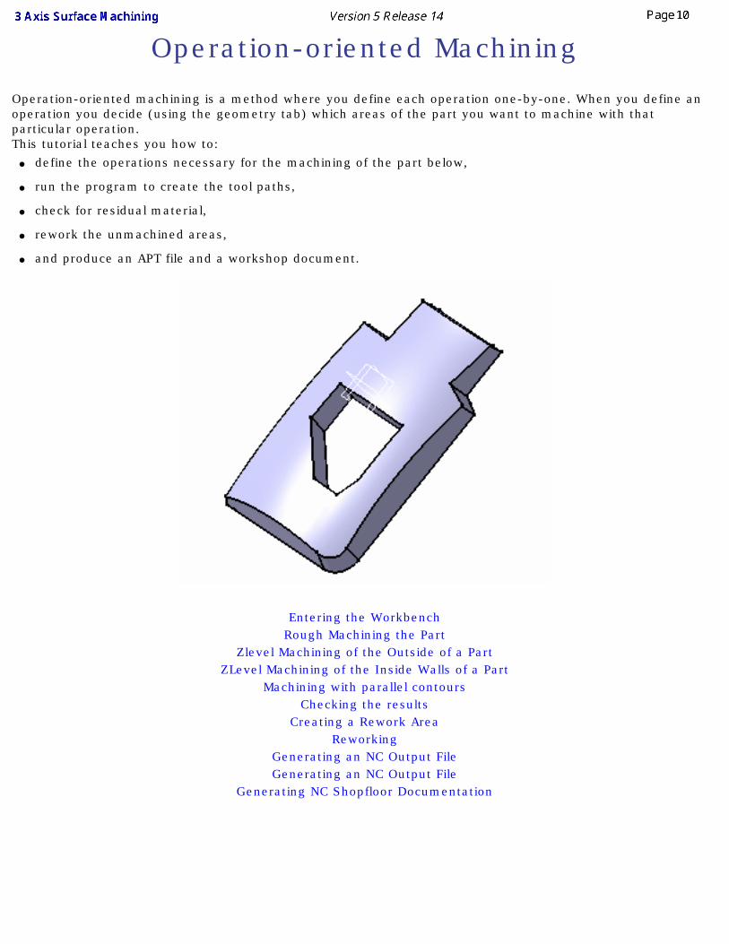
Operation-oriented machining is a method where you define each operation one-by-one. When you define an operation you decide (using the geometry tab) which areas of the part you want to machine with that particular operation.This tutorial teaches you how to:
● define the operations necessary for the machining of the part below,
● run the program to create the tool paths,
● check for residual material,
● rework the unmachined areas,
● and produce an APT file and a workshop document.
Entering the WorkbenchRough Machining the Part
Zlevel Machining of the Outside of a PartZLevel Machining of the Inside Walls of a Part
Machining with parallel contoursChecking the results
Creating a Rework AreaReworking
Generating an NC Output FileGenerating an NC Output File
Generating NC Shopfloor Documentation
Entering the Workbench
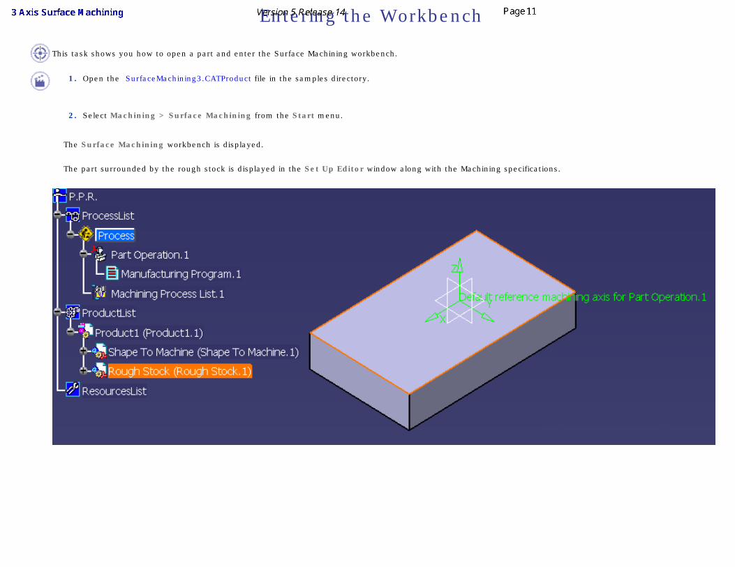
This task shows you how to open a part and enter the Surface Machining workbench.
1. Open the SurfaceMachining3.CATProduct file in the samples directory.
2. Select Machining > Surface Machining from the Start menu.
The Surface Machining workbench is displayed.
The part surrounded by the rough stock is displayed in the Set Up Editor window along with the Machining specifications.
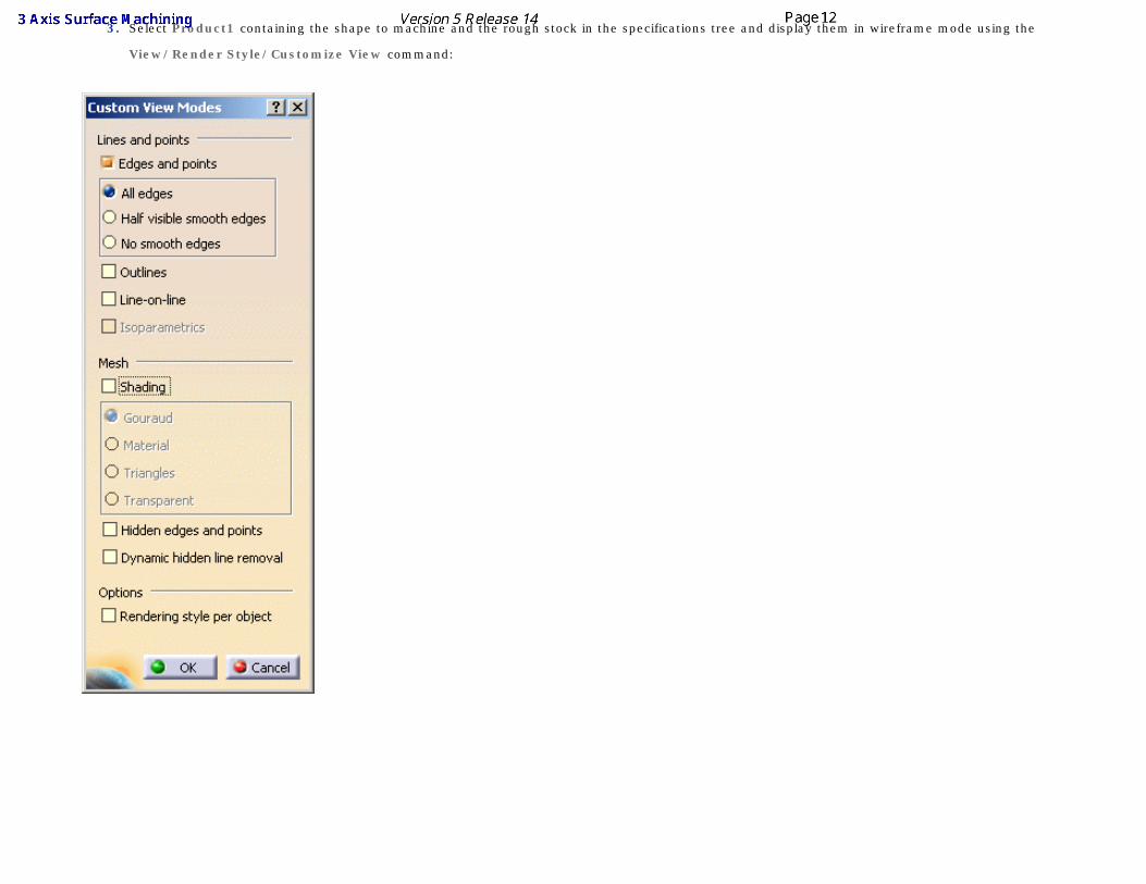
3. Select Product1 containing the shape to machine and the rough stock in the specifications tree and display them in wireframe mode using the
View/Render Style/Customize View command:
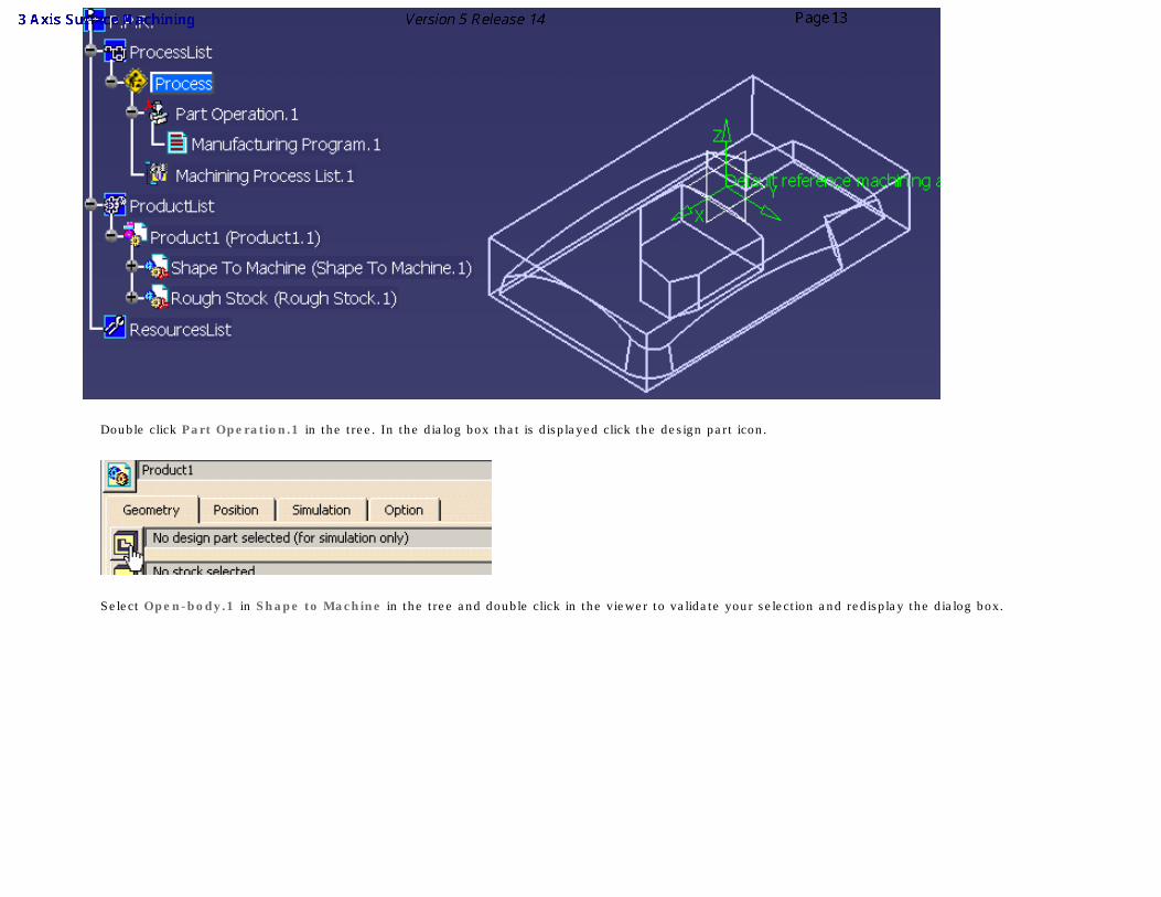
Double click Part Operation.1 in the tree. In the dialog box that is displayed click the design part icon.
Select Open-body.1 in Shape to Machine in the tree and double click in the viewer to validate your selection and redisplay the dialog box.
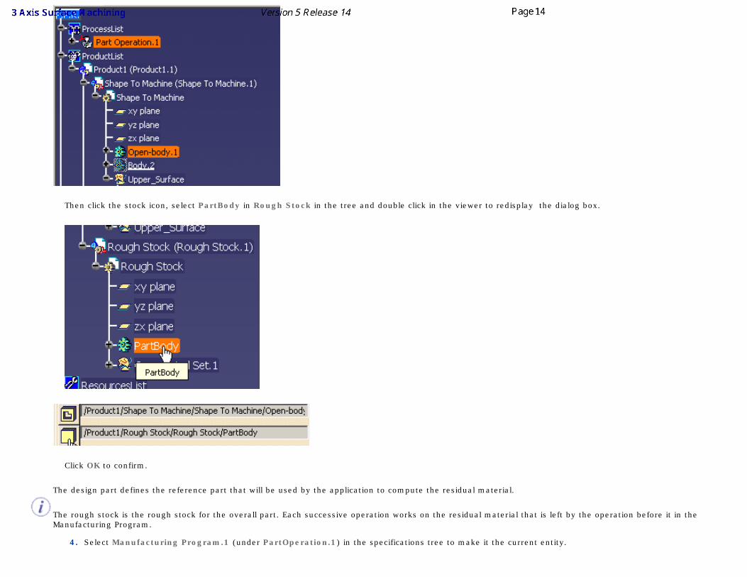
Then click the stock icon, select PartBody in Rough Stock in the tree and double click in the viewer to redisplay the dialog box.
Click OK to confirm.
The design part defines the reference part that will be used by the application to compute the residual material.
The rough stock is the rough stock for the overall part. Each successive operation works on the residual material that is left by the operation before it in the Manufacturing Program.
4. Select Manufacturing Program.1 (under PartOperation.1) in the specifications tree to make it the current entity.
A program must be current before you can insert program entities such as machining operations, tools and auxiliary commands.
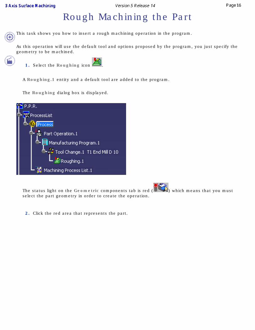
Rough Machining the PartThis task shows you how to insert a rough machining operation in the program.
As this operation will use the default tool and options proposed by the program, you just specify the geometry to be machined.
1. Select the Roughing icon .
A Roughing.1 entity and a default tool are added to the program.
The Roughing dialog box is displayed.
The status light on the Geometric components tab is red ( ) which means that you must select the part geometry in order to create the operation.
2. Click the red area that represents the part.
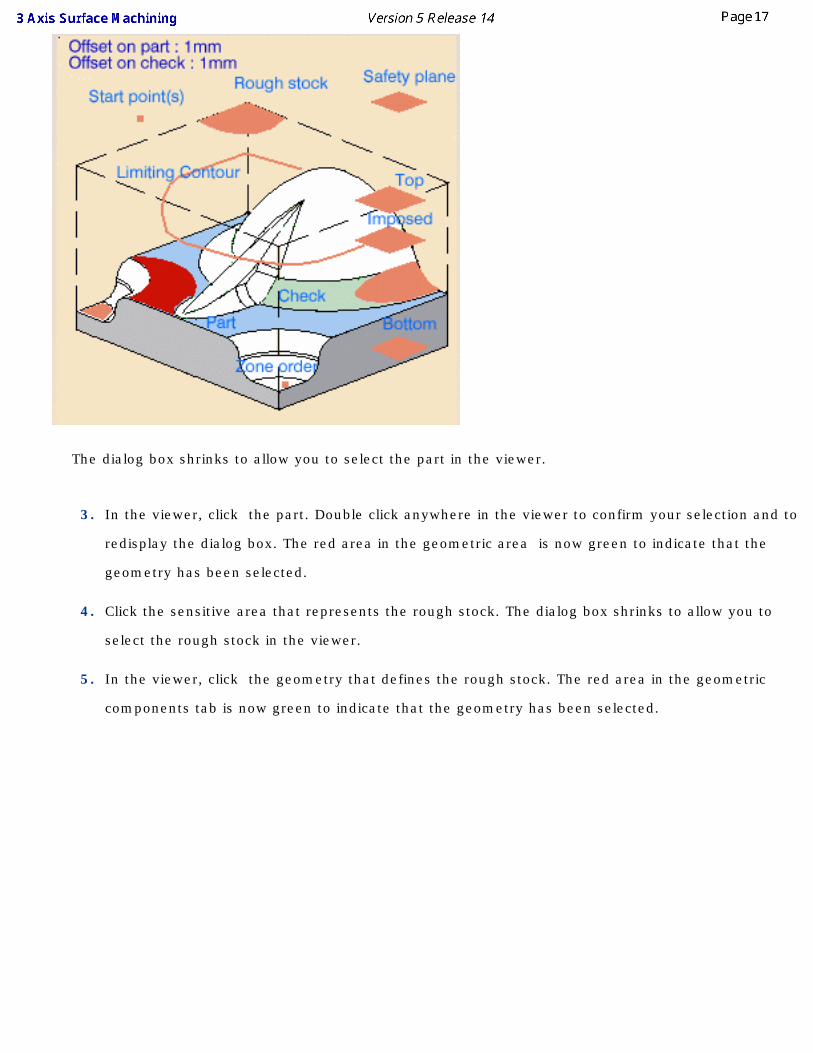
The dialog box shrinks to allow you to select the part in the viewer.
3. In the viewer, click the part. Double click anywhere in the viewer to confirm your selection and to
redisplay the dialog box. The red area in the geometric area is now green to indicate that the
geometry has been selected.
4. Click the sensitive area that represents the rough stock. The dialog box shrinks to allow you to
select the rough stock in the viewer.
5. In the viewer, click the geometry that defines the rough stock. The red area in the geometric
components tab is now green to indicate that the geometry has been selected.
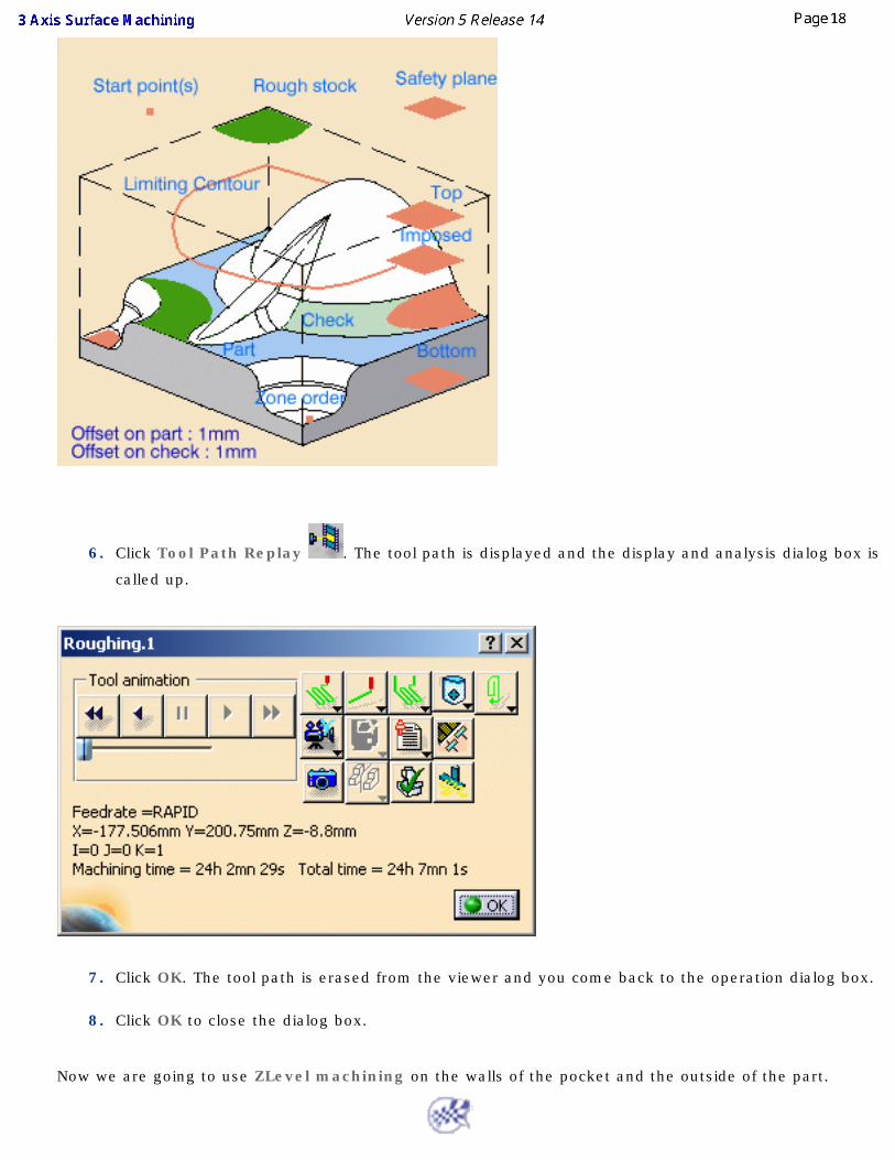
6. Click Tool Path Replay . The tool path is displayed and the display and analysis dialog box is
called up.
7. Click OK. The tool path is erased from the viewer and you come back to the operation dialog box.
8. Click OK to close the dialog box.
Now we are going to use ZLevel machining on the walls of the pocket and the outside of the part.
ZLevel Machining of the Outside of a Part
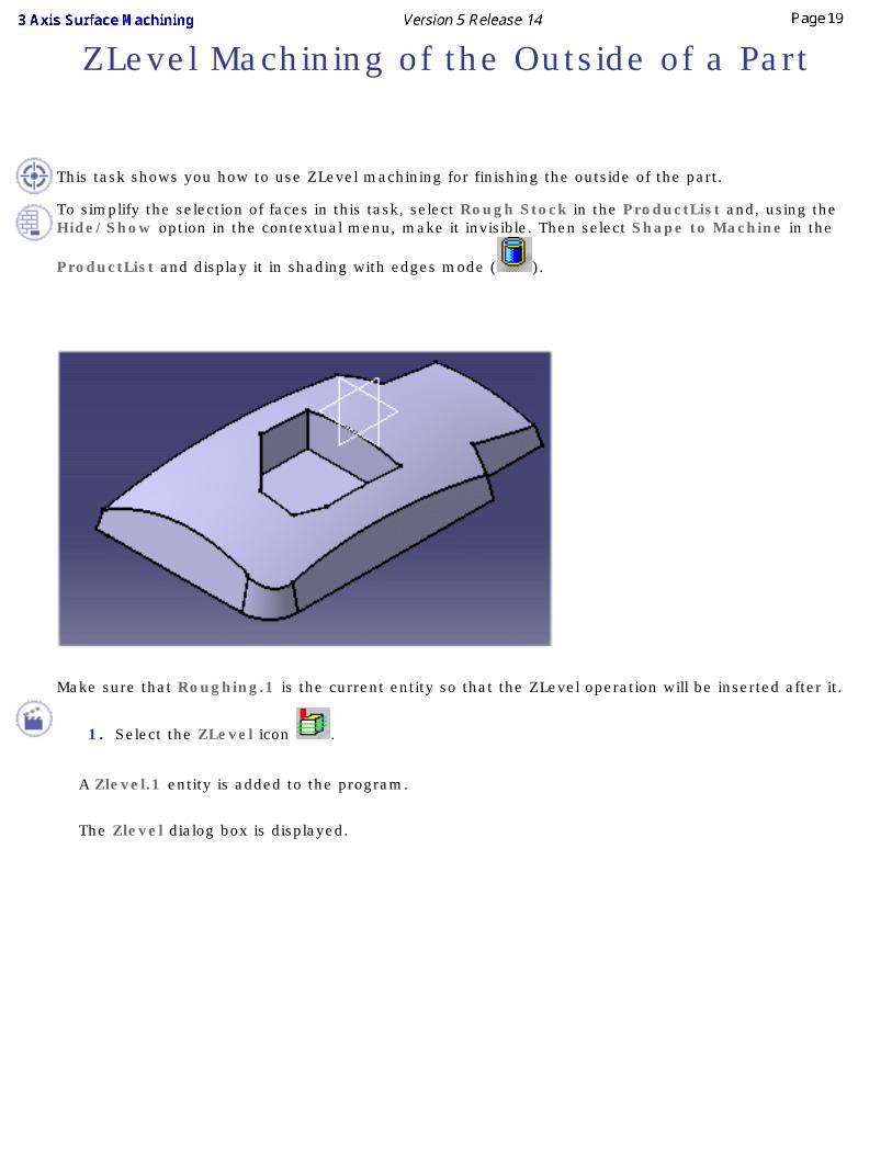
This task shows you how to use ZLevel machining for finishing the outside of the part.
To simplify the selection of faces in this task, select Rough Stock in the ProductList and, using the Hide/Show option in the contextual menu, make it invisible. Then select Shape to Machine in the
ProductList and display it in shading with edges mode ( ).
Make sure that Roughing.1 is the current entity so that the ZLevel operation will be inserted after it.
1. Select the ZLevel icon .
A Zlevel.1 entity is added to the program.
The Zlevel dialog box is displayed.
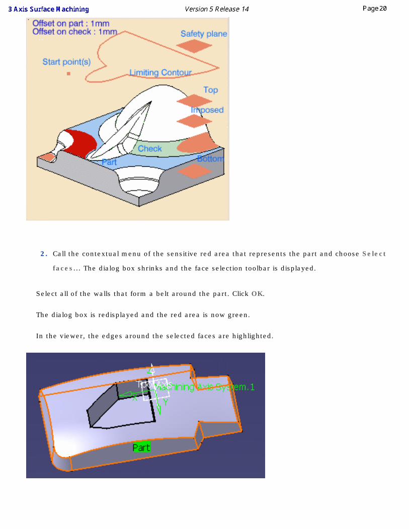
2. Call the contextual menu of the sensitive red area that represents the part and choose Select
faces... The dialog box shrinks and the face selection toolbar is displayed.
Select all of the walls that form a belt around the part. Click OK.
The dialog box is redisplayed and the red area is now green.
In the viewer, the edges around the selected faces are highlighted.
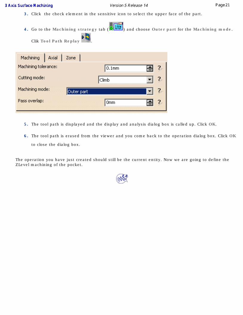
3. Click the check element in the sensitive icon to select the upper face of the part.
4. Go to the Machining strategy tab ( ) and choose Outer part for the Machining mode.
Clik Tool Path Replay .
5. The tool path is displayed and the display and analysis dialog box is called up. Click OK.
6. The tool path is erased from the viewer and you come back to the operation dialog box. Click OK
to close the dialog box.
The operation you have just created should still be the current entity. Now we are going to define the ZLevel machining of the pocket.
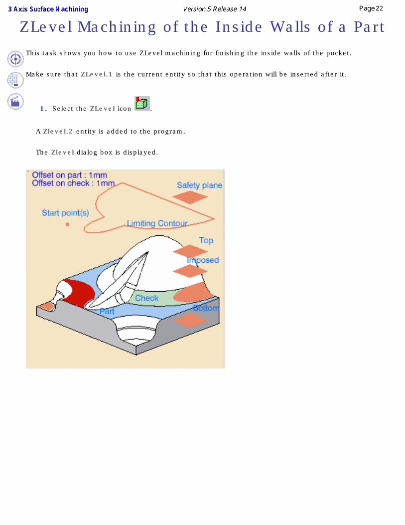
ZLevel Machining of the Inside Walls of a PartThis task shows you how to use ZLevel machining for finishing the inside walls of the pocket.
Make sure that ZLevel.1 is the current entity so that this operation will be inserted after it.
1. Select the ZLevel icon .
A Zlevel.2 entity is added to the program.
The Zlevel dialog box is displayed.
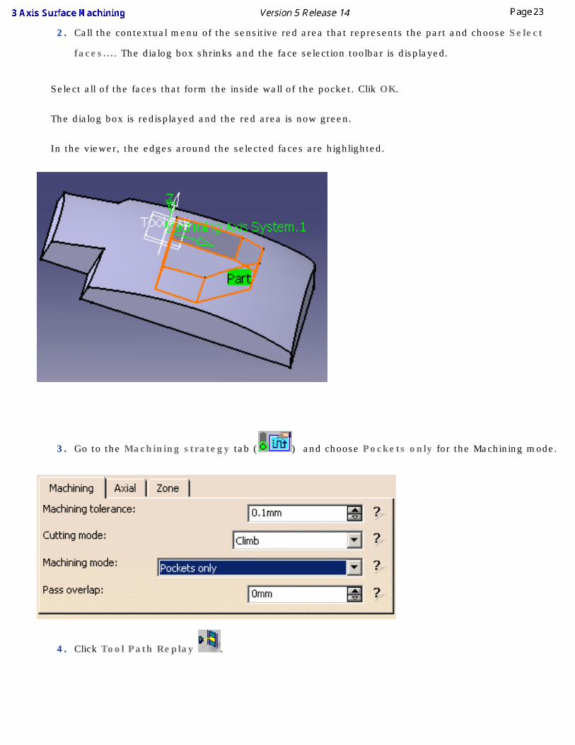
2. Call the contextual menu of the sensitive red area that represents the part and choose Select
faces.... The dialog box shrinks and the face selection toolbar is displayed.
Select all of the faces that form the inside wall of the pocket. Clik OK.
The dialog box is redisplayed and the red area is now green.
In the viewer, the edges around the selected faces are highlighted.
3. Go to the Machining strategy tab ( ) and choose Pockets only for the Machining mode.
4. Click Tool Path Replay .
5. The tool path is displayed and the display and analysis dialog box is called up.
Click OK.
6. The tool path is erased from the viewer and you come back to the operation dialog box.
Click OK to close the dialog box.
The operation you have just created should still be the current entity.
Now we are going to define a sweeping operation for the top surface of the part and the bottom of the pocket.
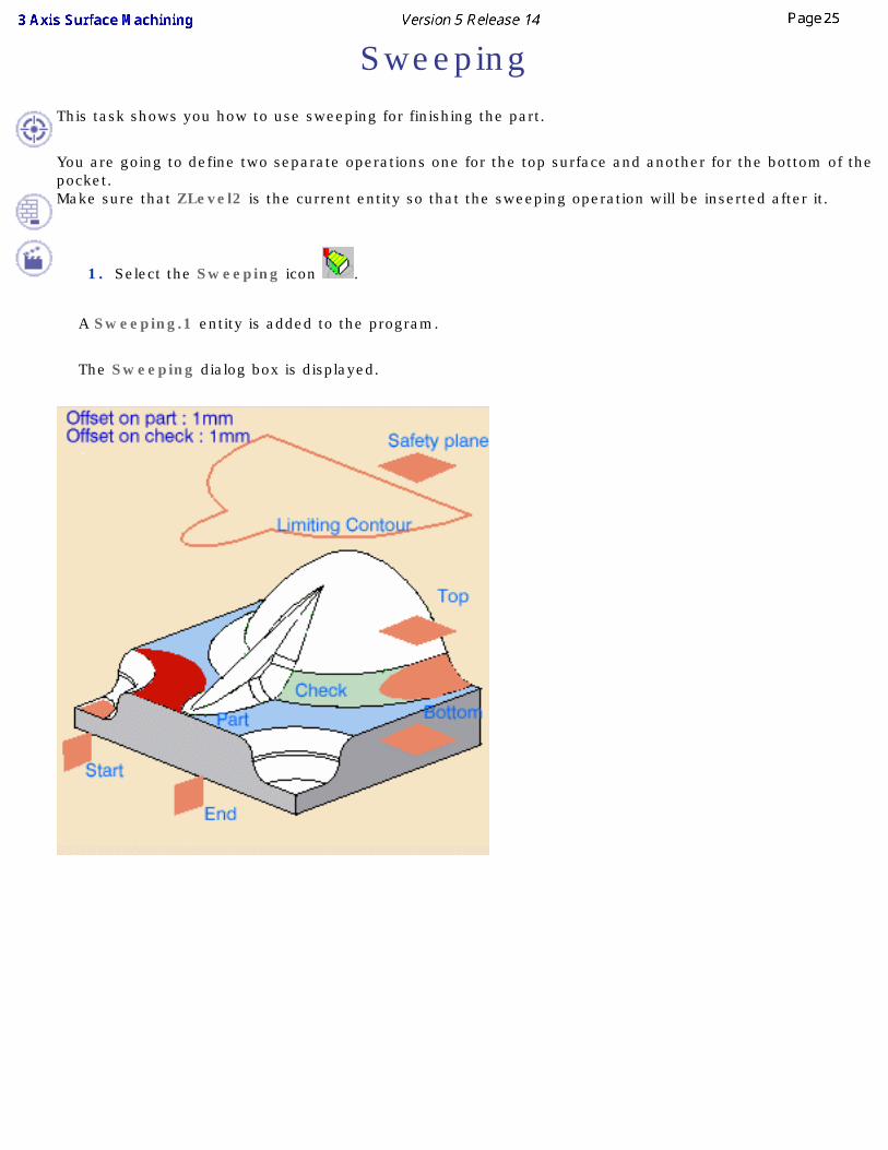
SweepingThis task shows you how to use sweeping for finishing the part.
You are going to define two separate operations one for the top surface and another for the bottom of the pocket.Make sure that ZLevel2 is the current entity so that the sweeping operation will be inserted after it.
1. Select the Sweeping icon .
A Sweeping.1 entity is added to the program.
The Sweeping dialog box is displayed.
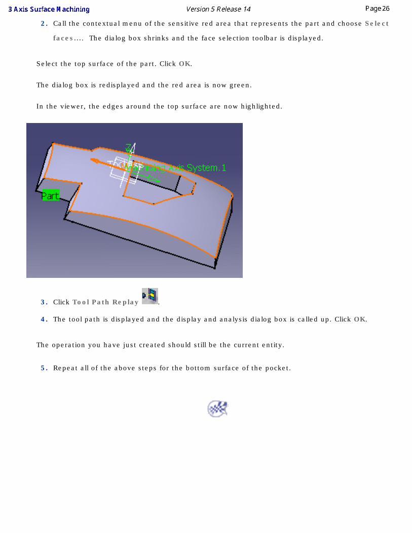
2. Call the contextual menu of the sensitive red area that represents the part and choose Select
faces.... The dialog box shrinks and the face selection toolbar is displayed.
Select the top surface of the part. Click OK.
The dialog box is redisplayed and the red area is now green.
In the viewer, the edges around the top surface are now highlighted.
3. Click Tool Path Replay .
4. The tool path is displayed and the display and analysis dialog box is called up. Click OK.
The operation you have just created should still be the current entity.
5. Repeat all of the above steps for the bottom surface of the pocket.
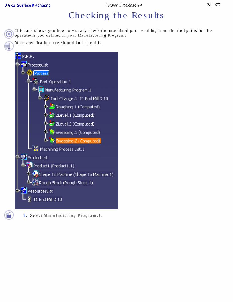
Checking the ResultsThis task shows you how to visually check the machined part resulting from the tool paths for the operations you defined in your Manufacturing Program.
Your specification tree should look like this.
1. Select Manufacturing Program.1.
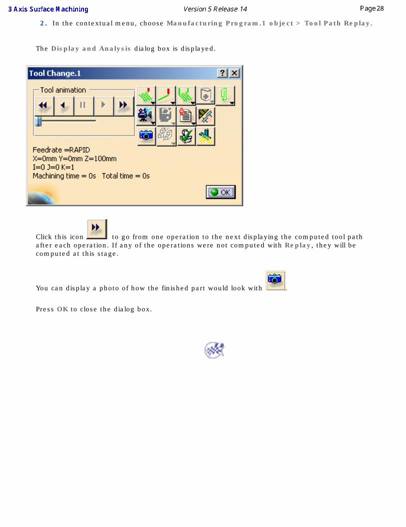
2. In the contextual menu, choose Manufacturing Program.1 object > Tool Path Replay.
The Display and Analysis dialog box is displayed.
Click this icon to go from one operation to the next displaying the computed tool path after each operation. If any of the operations were not computed with Replay, they will be computed at this stage.
You can display a photo of how the finished part would look with .
Press OK to close the dialog box.
Creating a Rework Area
This task shows you how to define an area to rework from the areas of the part that were not machined with the tool used in the operations.
You must compute the tool paths for your Manufacturing Program first.
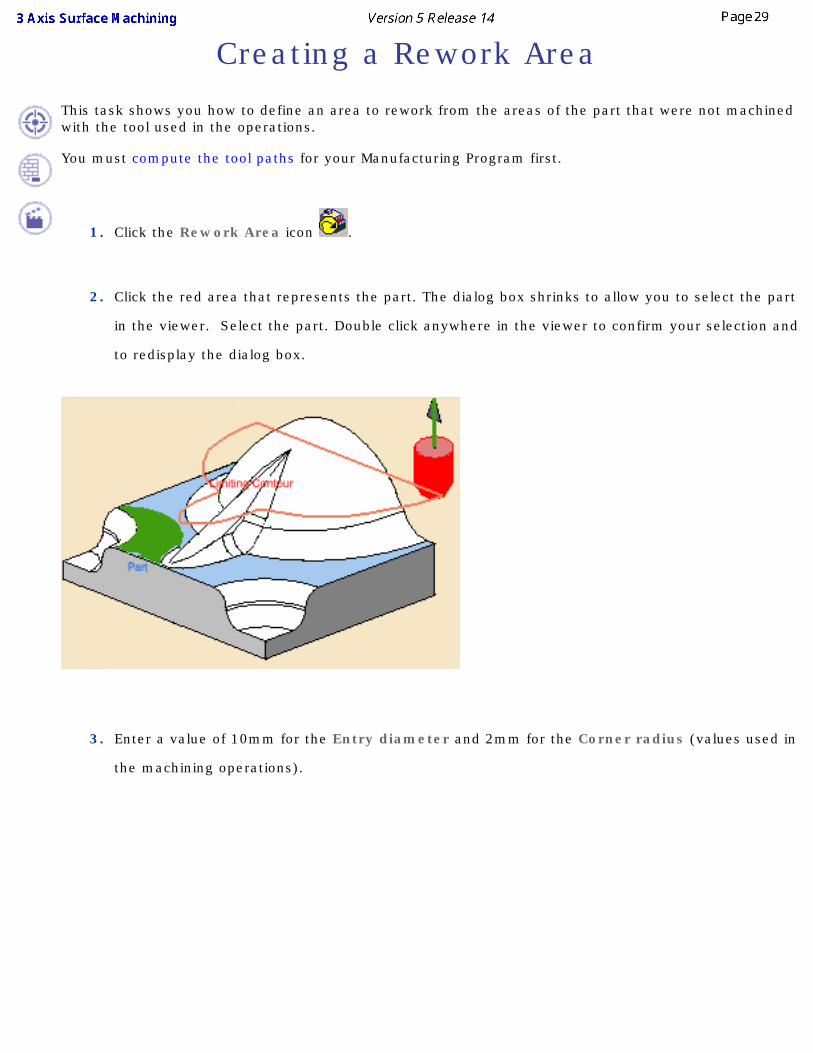
1. Click the Rework Area icon .
2. Click the red area that represents the part. The dialog box shrinks to allow you to select the part
in the viewer. Select the part. Double click anywhere in the viewer to confirm your selection and
to redisplay the dialog box.
3. Enter a value of 10mm for the Entry diameter and 2mm for the Corner radius (values used in
the machining operations).
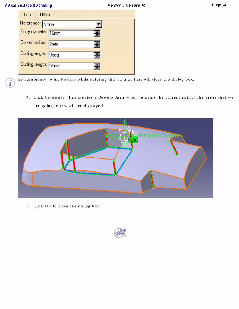
Be careful not to hit Return while entering this data as that will close the dialog box.
4. Click Compute. This creates a Rework Area which remains the current entity. The areas that we
are going to rework are displayed.
5. Click OK to close the dialog box.
ReworkingThis task shows you how to rework the areas of the part that have not been machined and were there is residual material.
You must have created a rework area. A rework area is an area that cannot be machined with a given tool.
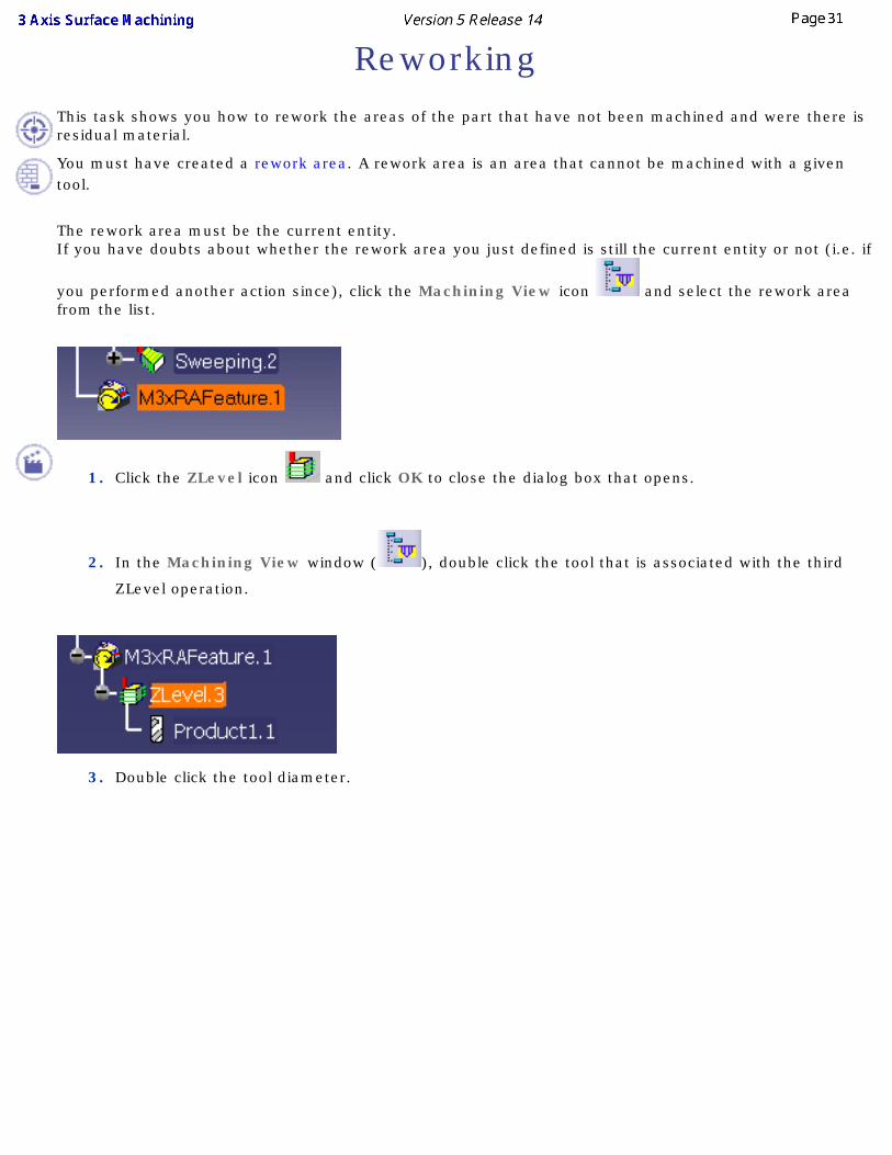
The rework area must be the current entity. If you have doubts about whether the rework area you just defined is still the current entity or not (i.e. if
you performed another action since), click the Machining View icon and select the rework area from the list.
1. Click the ZLevel icon and click OK to close the dialog box that opens.
2. In the Machining View window ( ), double click the tool that is associated with the third
ZLevel operation.
3. Double click the tool diameter.
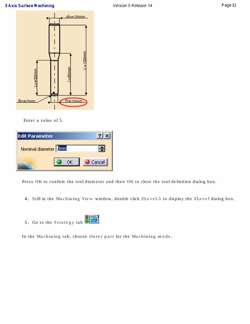
Enter a value of 5.
Press OK to confirm the tool diameter and then OK to close the tool definition dialog box.
4. Still in the Machining View window, double click ZLevel.3 to display the ZLevel dialog box.
5. Go to the Strategy tab .
In the Machining tab, choose Outer part for the Machining mode.
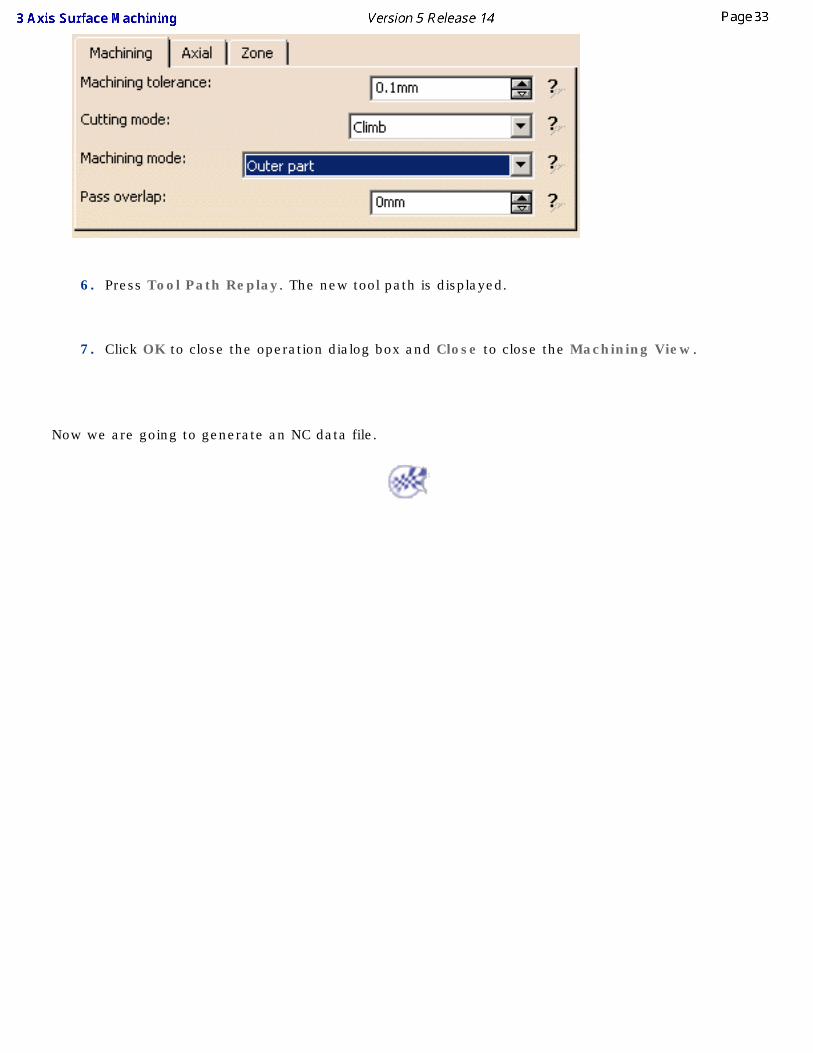
6. Press Tool Path Replay. The new tool path is displayed.
7. Click OK to close the operation dialog box and Close to close the Machining View.
Now we are going to generate an NC data file.
Generating an NC Output FileThis task explains how to interactively generate NC code from the program you have just created.
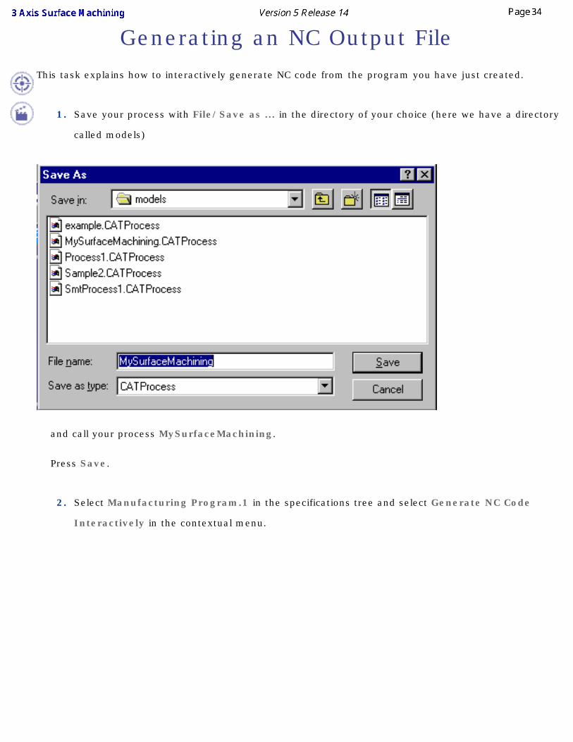
1. Save your process with File/Save as ... in the directory of your choice (here we have a directory
called models)
and call your process MySurfaceMachining.
Press Save.
2. Select Manufacturing Program.1 in the specifications tree and select Generate NC Code
Interactively in the contextual menu.
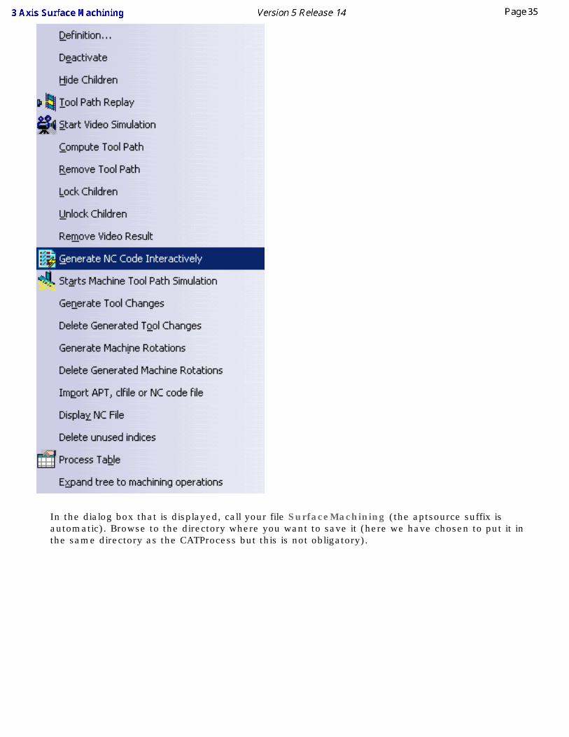
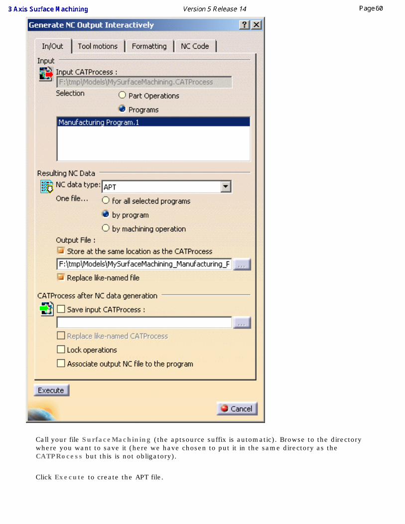
In the dialog box that is displayed, call your file SurfaceMachining (the aptsource suffix is automatic). Browse to the directory where you want to save it (here we have chosen to put it in the same directory as the CATProcess but this is not obligatory).
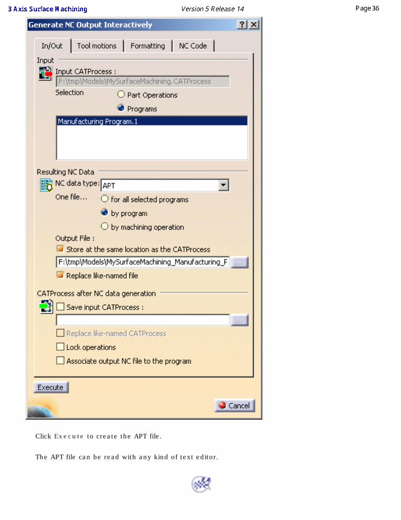
Click Execute to create the APT file.
The APT file can be read with any kind of text editor.
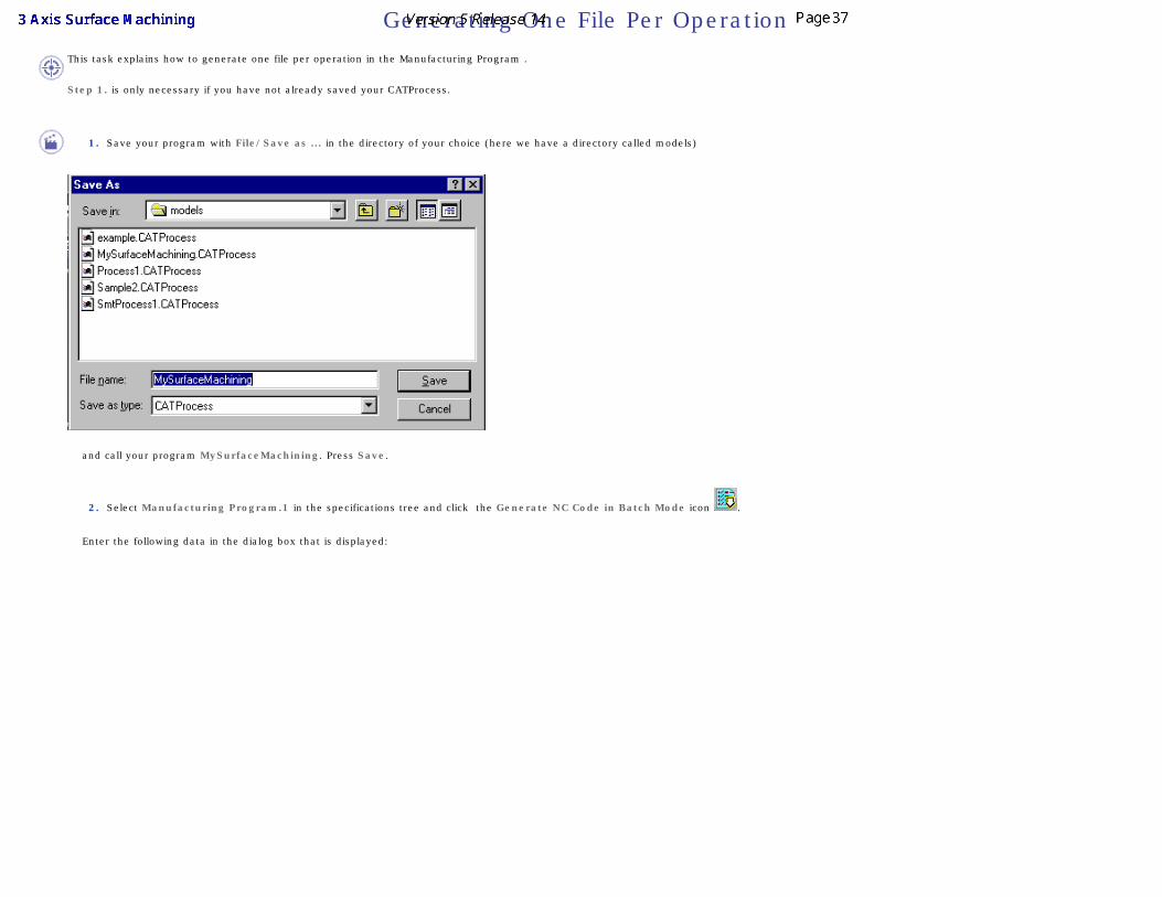
Generating One File Per OperationThis task explains how to generate one file per operation in the Manufacturing Program .
Step 1. is only necessary if you have not already saved your CATProcess.
1. Save your program with File/Save as ... in the directory of your choice (here we have a directory called models)
and call your program MySurfaceMachining. Press Save.
2. Select Manufacturing Program.1 in the specifications tree and click the Generate NC Code in Batch Mode icon .
Enter the following data in the dialog box that is displayed:
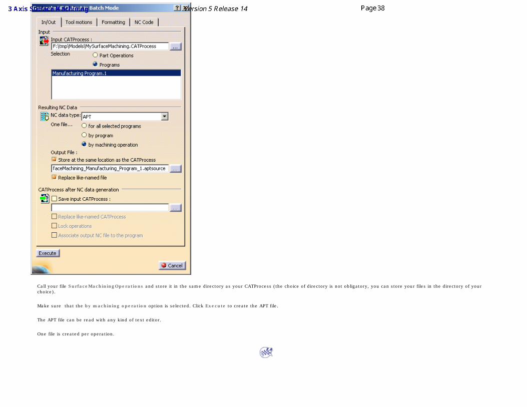
Call your file SurfaceMachiningOperations and store it in the same directory as your CATProcess (the choice of directory is not obligatory, you can store your files in the directory of your choice).
Make sure that the by machining operation option is selected. Click Execute to create the APT file.
The APT file can be read with any kind of text editor.
One file is created per operation.
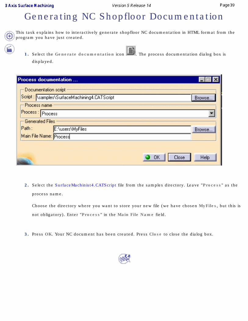
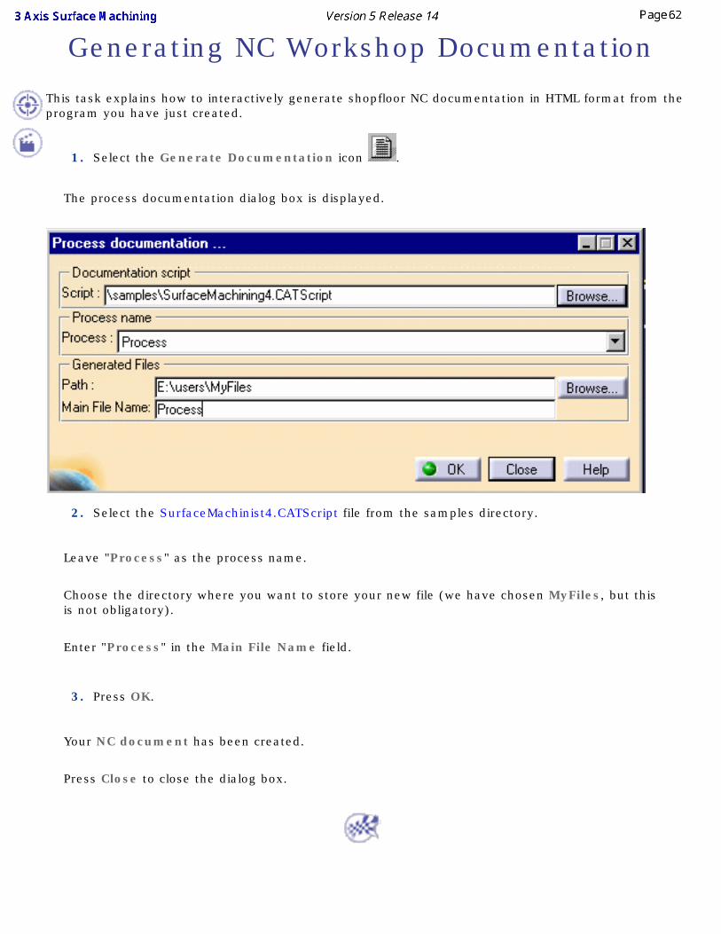
Generating NC Shopfloor DocumentationThis task explains how to interactively generate shopfloor NC documentation in HTML format from the program you have just created.
1. Select the Generate documentation icon . The process documentation dialog box is
displayed.
2. Select the SurfaceMachinist4.CATScript file from the samples directory. Leave "Process" as the
process name.
Choose the directory where you want to store your new file (we have chosen MyFiles, but this is
not obligatory). Enter "Process" in the Main File Name field.
3. Press OK. Your NC document has been created. Press Close to close the dialog box.
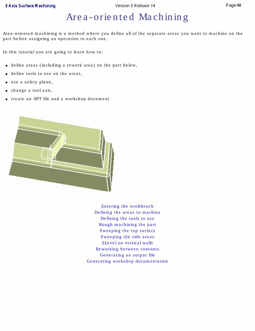
Area-oriented MachiningArea-oriented machining is a method where you define all of the separate areas you want to machine on the part before assigning an operation to each one.
In this tutorial you are going to learn how to:
● define areas (including a rework area) on the part below,
● define tools to use on the areas,
● use a safety plane,
● change a tool axis,
● create an APT file and a workshop document.
Entering the workbenchDefining the areas to machine
Defining the tools to useRough machining the partSweeping the top surfaceSweeping the side areasZLevel on vertical walls
Reworking between contoursGenerating an output file
Generating workshop documentation
Entering the Workbench
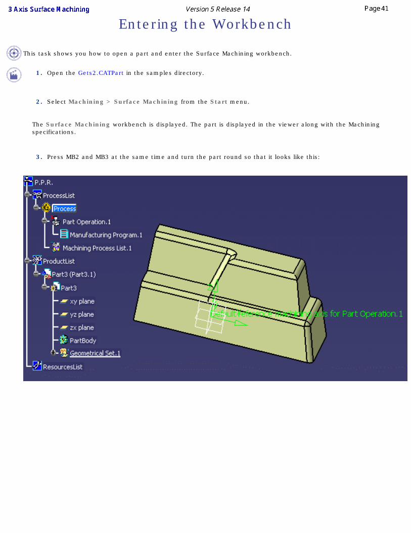
This task shows you how to open a part and enter the Surface Machining workbench.
1. Open the Gets2.CATPart in the samples directory.
2. Select Machining > Surface Machining from the Start menu.
The Surface Machining workbench is displayed. The part is displayed in the viewer along with the Machining specifications.
3. Press MB2 and MB3 at the same time and turn the part round so that it looks like this:
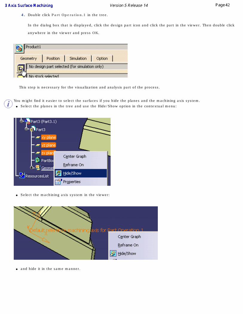
4. Double click Part Operation.1 in the tree.
In the dialog box that is displayed, click the design part icon and click the part in the viewer. Then double click
anywhere in the viewer and press OK.
This step is necessary for the visualization and analysis part of the process.
You might find it easier to select the surfaces if you hide the planes and the machining axis system. ● Select the planes in the tree and use the Hide/Show option in the contextual menu:
● Select the machining axis system in the viewer:
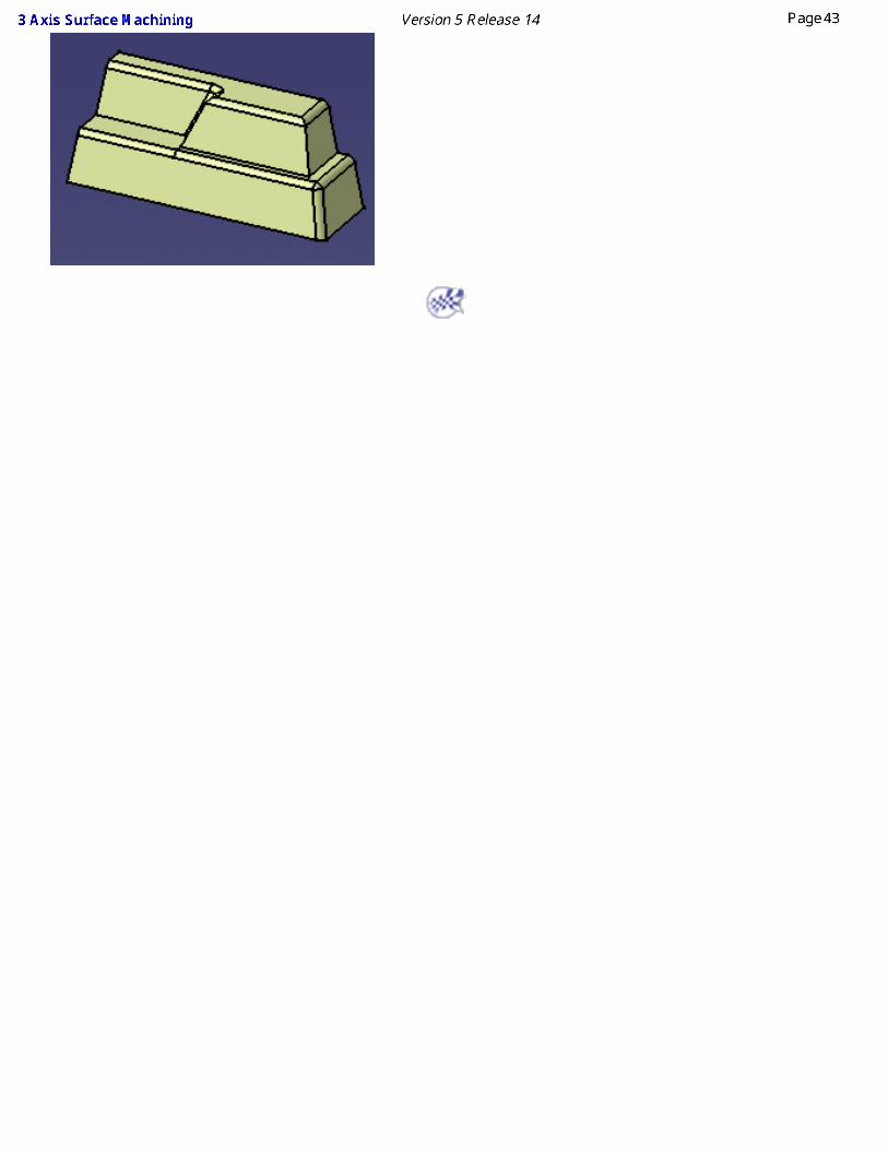
● and hide it in the same manner.
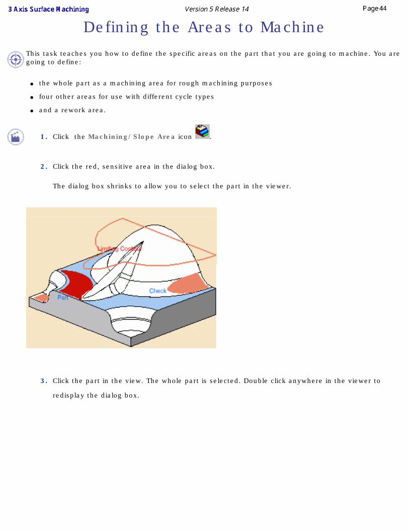
Defining the Areas to MachineThis task teaches you how to define the specific areas on the part that you are going to machine. You are going to define:
● the whole part as a machining area for rough machining purposes
● four other areas for use with different cycle types
● and a rework area.
1. Click the Machining/Slope Area icon .
2. Click the red, sensitive area in the dialog box.
The dialog box shrinks to allow you to select the part in the viewer.
3. Click the part in the view. The whole part is selected. Double click anywhere in the viewer to
redisplay the dialog box.
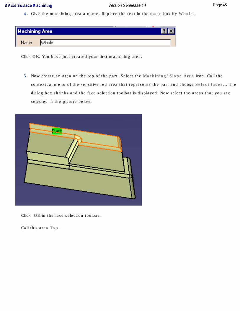
4. Give the machining area a name. Replace the text in the name box by Whole.
Click OK. You have just created your first machining area.
5. Now create an area on the top of the part. Select the Machining/Slope Area icon. Call the
contextual menu of the sensitive red area that represents the part and choose Select faces... The
dialog box shrinks and the face selection toolbar is displayed. Now select the areas that you see
selected in the picture below.
Click OK in the face selection toolbar.
Call this area Top.
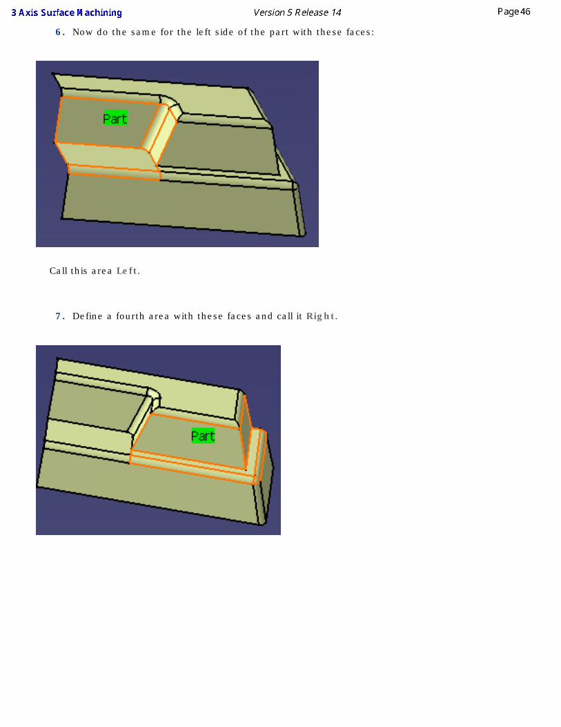
6. Now do the same for the left side of the part with these faces:
Call this area Left.
7. Define a fourth area with these faces and call it Right.
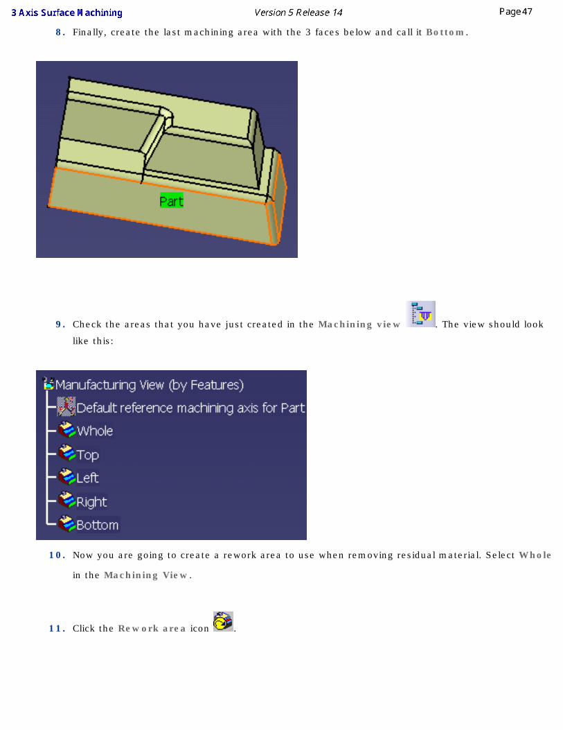
8. Finally, create the last machining area with the 3 faces below and call it Bottom.
9. Check the areas that you have just created in the Machining view . The view should look
like this:
10. Now you are going to create a rework area to use when removing residual material. Select Whole
in the Machining View.
11. Click the Rework area icon .
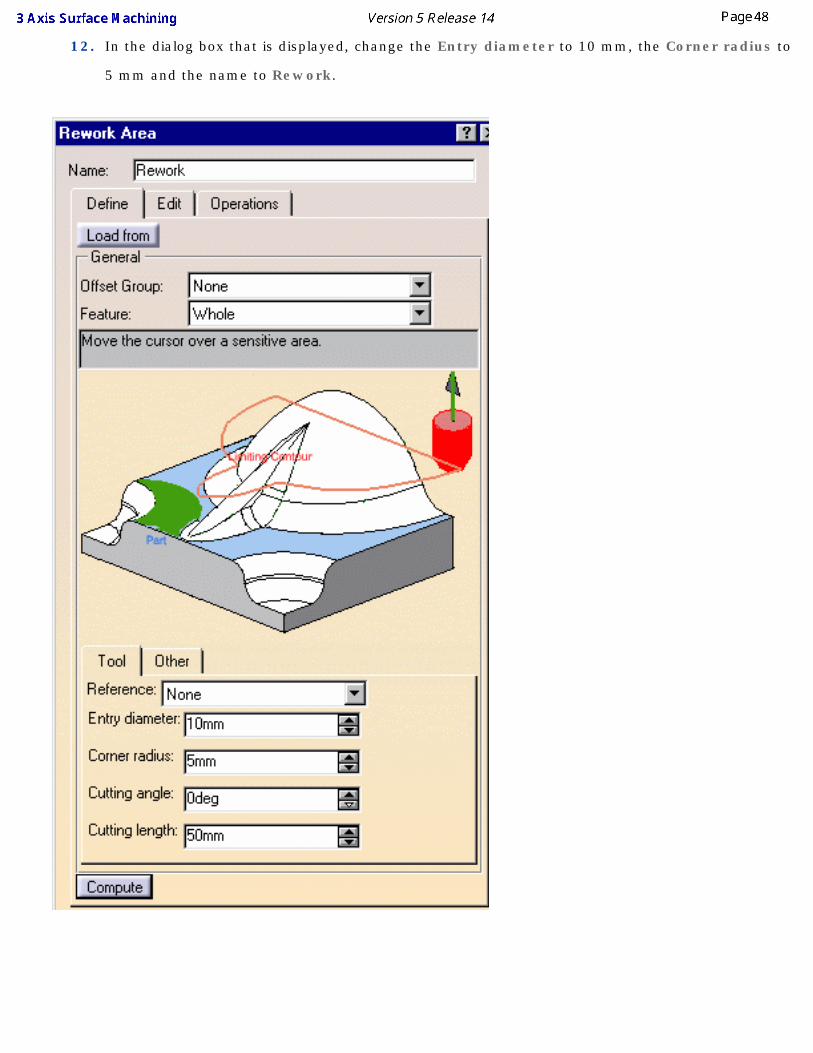
12. In the dialog box that is displayed, change the Entry diameter to 10 mm, the Corner radius to
5 mm and the name to Rework.
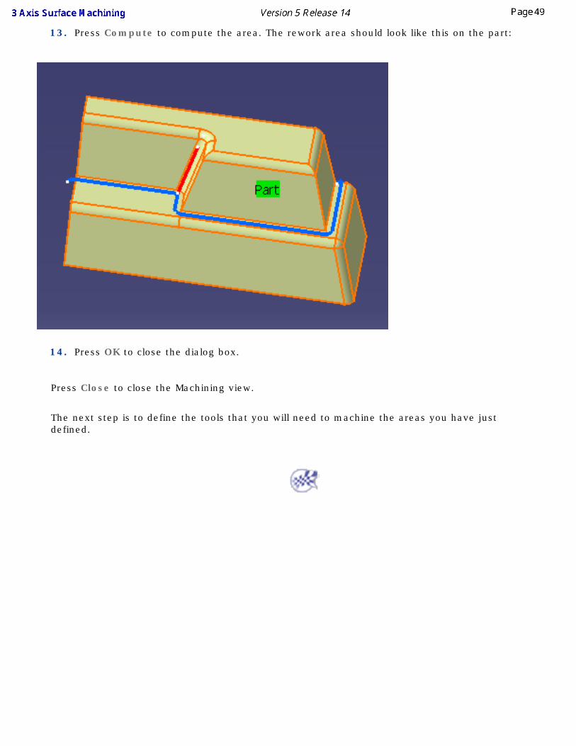
13. Press Compute to compute the area. The rework area should look like this on the part:
14. Press OK to close the dialog box.
Press Close to close the Machining view.
The next step is to define the tools that you will need to machine the areas you have just defined.
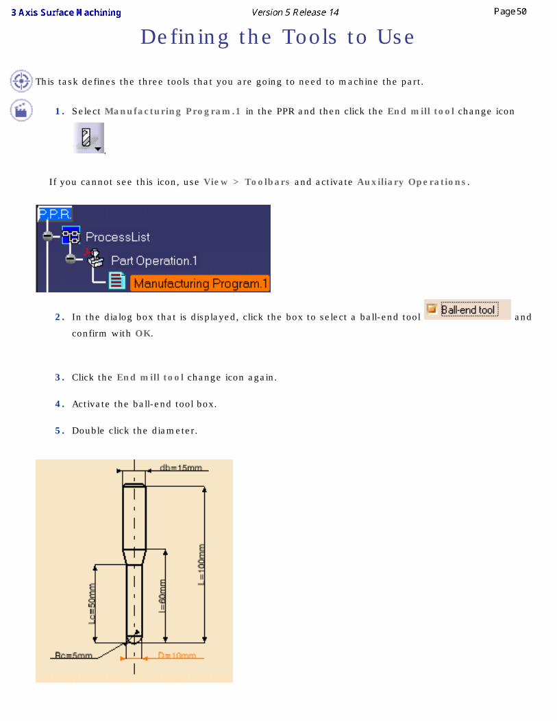
Defining the Tools to Use
This task defines the three tools that you are going to need to machine the part.
1. Select Manufacturing Program.1 in the PPR and then click the End mill tool change icon
.
If you cannot see this icon, use View > Toolbars and activate Auxiliary Operations.
2. In the dialog box that is displayed, click the box to select a ball-end tool and
confirm with OK.
3. Click the End mill tool change icon again.
4. Activate the ball-end tool box.
5. Double click the diameter.
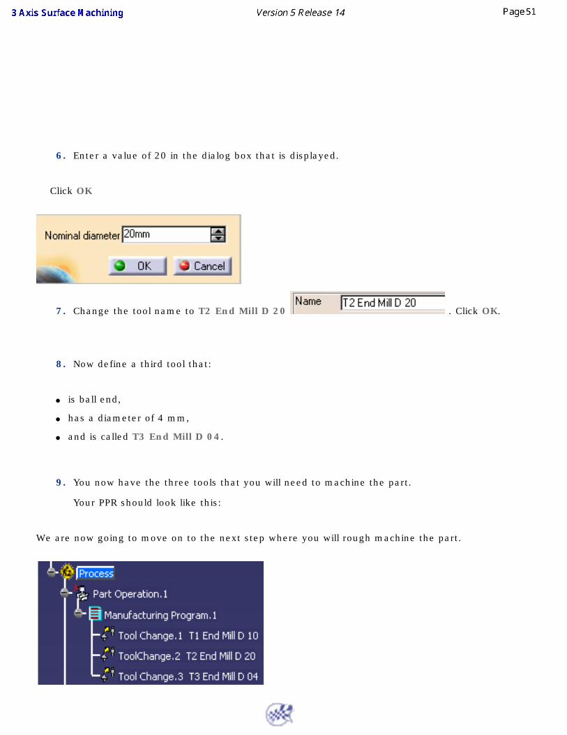
6. Enter a value of 20 in the dialog box that is displayed.
Click OK
7. Change the tool name to T2 End Mill D 20 . Click OK.
8. Now define a third tool that:
● is ball end,
● has a diameter of 4 mm,
● and is called T3 End Mill D 04.
9. You now have the three tools that you will need to machine the part.
Your PPR should look like this:
We are now going to move on to the next step where you will rough machine the part.
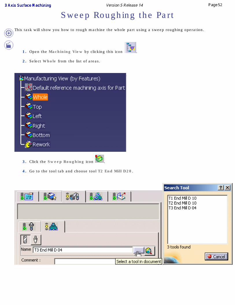
Sweep Roughing the PartThis task will show you how to rough machine the whole part using a sweep roughing operation.
1. Open the Machining View by clicking this icon .
2. Select Whole from the list of areas.
3. Click the Sweep Roughing icon .
4. Go to the tool tab and choose tool T2 End Mill D20.
5. Press Tool Path Replay to compute the operation. The toolpath is displayed on the part. Press
OK to close the small dialog box that is displayed (bottom right).
6. Press OK to close the operation dialog box.
7. Now you are going to machine the Top surface.
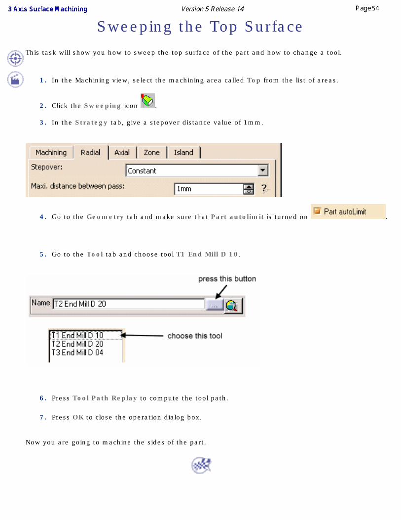
Sweeping the Top SurfaceThis task will show you how to sweep the top surface of the part and how to change a tool.
1. In the Machining view, select the machining area called Top from the list of areas.
2. Click the Sweeping icon .
3. In the Strategy tab, give a stepover distance value of 1mm.
4. Go to the Geometry tab and make sure that Part autolimit is turned on .
5. Go to the Tool tab and choose tool T1 End Mill D 10.
6. Press Tool Path Replay to compute the tool path.
7. Press OK to close the operation dialog box.
Now you are going to machine the sides of the part.
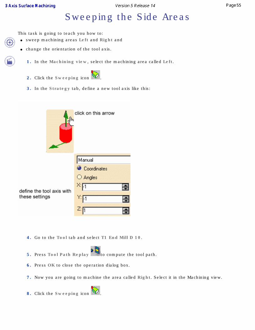
Sweeping the Side Areas
This task is going to teach you how to: ● sweep machining areas Left and Right and
● change the orientation of the tool axis.
1. In the Machining view, select the machining area called Left.
2. Click the Sweeping icon .
3. In the Strategy tab, define a new tool axis like this:
4. Go to the Tool tab and select T1 End Mill D 10.
5. Press Tool Path Replay to compute the tool path.
6. Press OK to close the operation dialog box.
7. Now you are going to machine the area called Right. Select it in the Machining view.
8. Click the Sweeping icon .
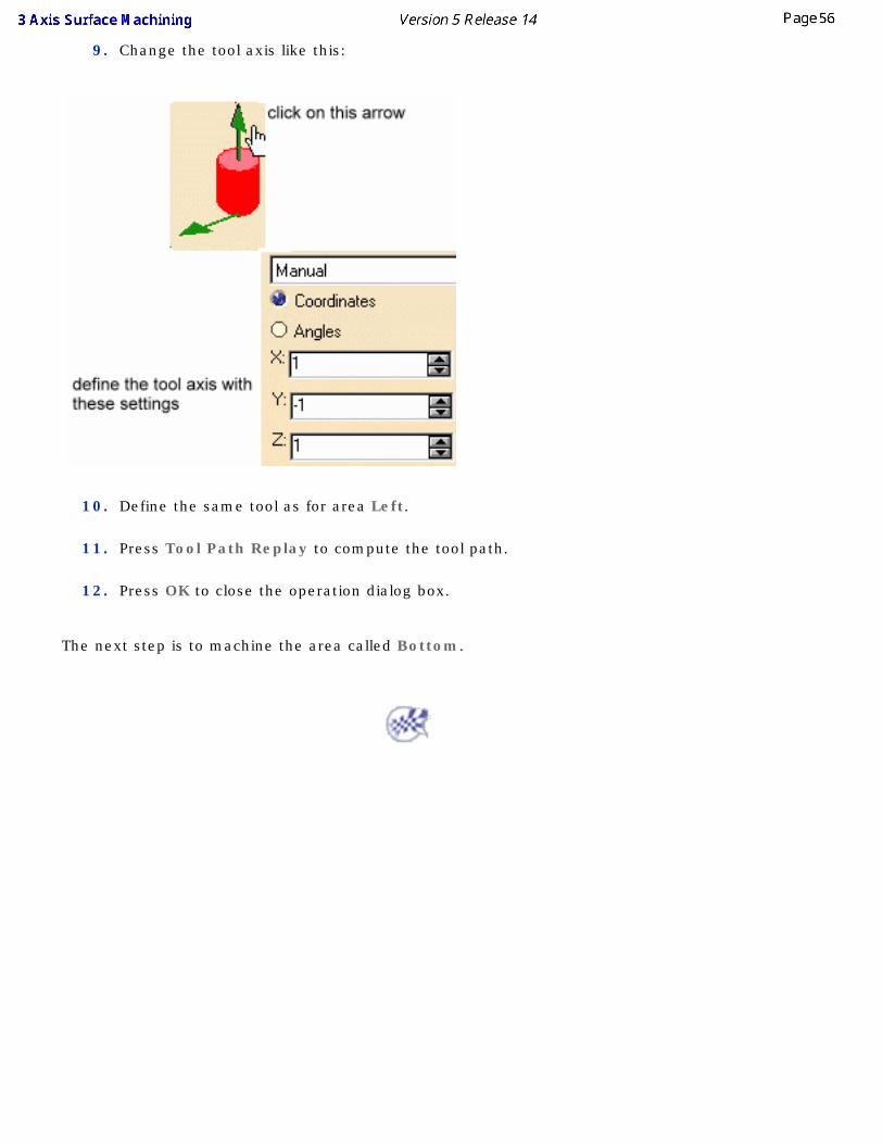
9. Change the tool axis like this:
10. Define the same tool as for area Left.
11. Press Tool Path Replay to compute the tool path.
12. Press OK to close the operation dialog box.
The next step is to machine the area called Bottom.
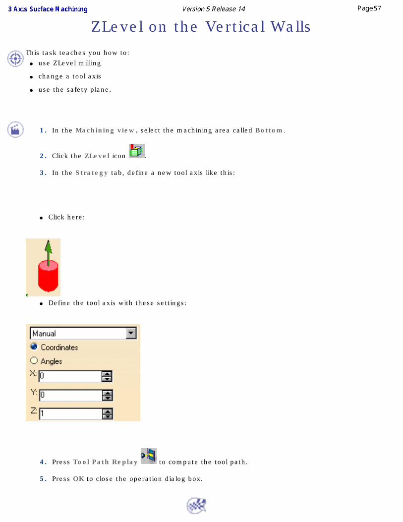
ZLevel on the Vertical WallsThis task teaches you how to:
● use ZLevel milling
● change a tool axis
● use the safety plane.
1. In the Machining view, select the machining area called Bottom.
2. Click the ZLevel icon .
3. In the Strategy tab, define a new tool axis like this:
● Click here:
● Define the tool axis with these settings:
4. Press Tool Path Replay to compute the tool path.
5. Press OK to close the operation dialog box.
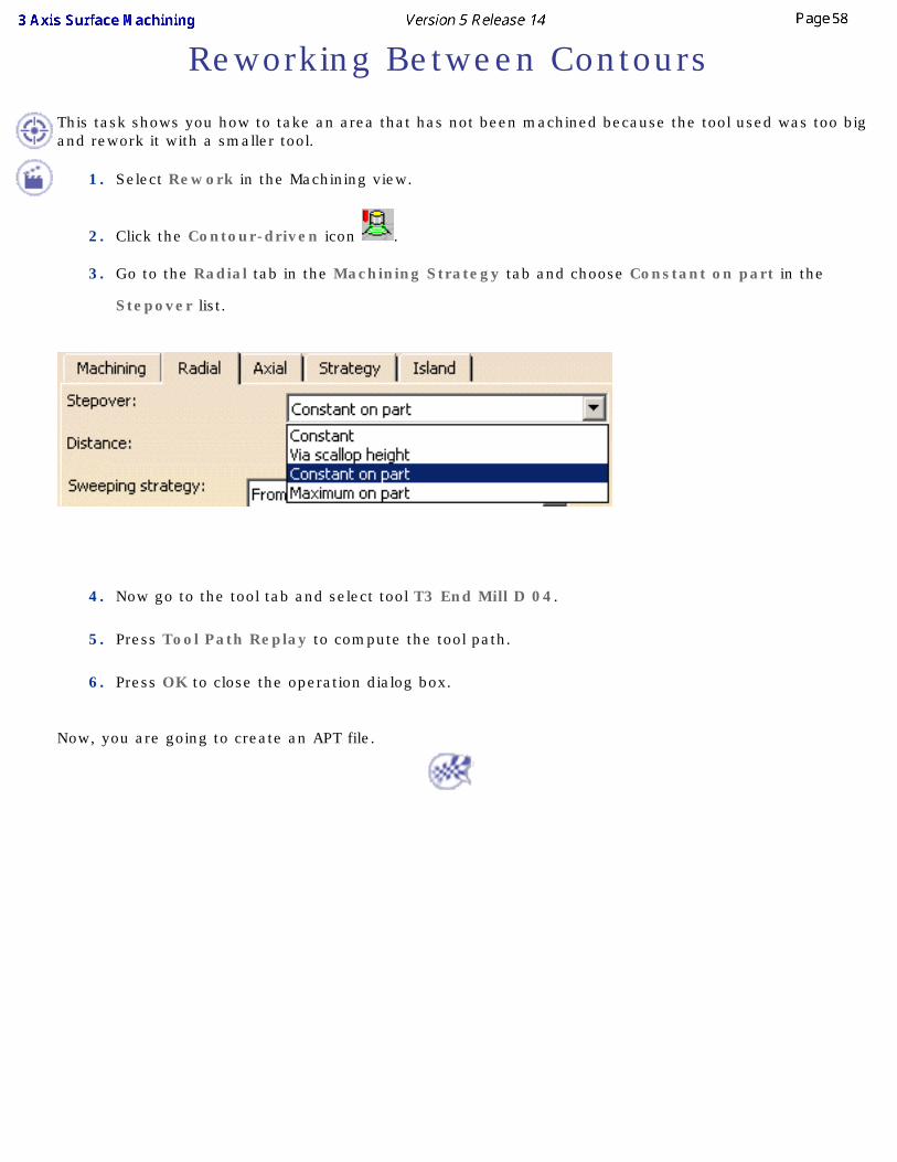
Reworking Between Contours
This task shows you how to take an area that has not been machined because the tool used was too big and rework it with a smaller tool.
1. Select Rework in the Machining view.
2. Click the Contour-driven icon .
3. Go to the Radial tab in the Machining Strategy tab and choose Constant on part in the
Stepover list.
4. Now go to the tool tab and select tool T3 End Mill D 04.
5. Press Tool Path Replay to compute the tool path.
6. Press OK to close the operation dialog box.
Now, you are going to create an APT file.
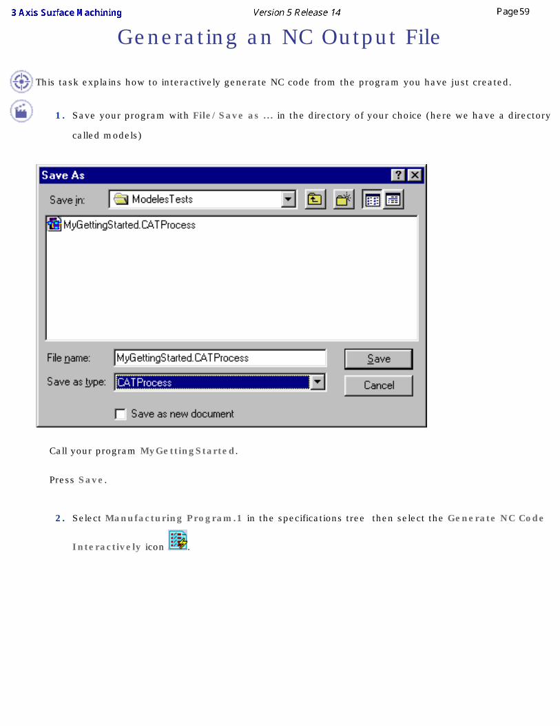
Generating an NC Output File
This task explains how to interactively generate NC code from the program you have just created.
1. Save your program with File/Save as ... in the directory of your choice (here we have a directory
called models)
Call your program MyGettingStarted.
Press Save.
2. Select Manufacturing Program.1 in the specifications tree then select the Generate NC Code
Interactively icon .
Call your file SurfaceMachining (the aptsource suffix is automatic). Browse to the directory where you want to save it (here we have chosen to put it in the same directory as the CATPRocess but this is not obligatory).
Click Execute to create the APT file.

The APT file can be read with any kind of editor.
Next you are going to generate workshop documentation in HTML format.
Generating NC Workshop Documentation
This task explains how to interactively generate shopfloor NC documentation in HTML format from the program you have just created.
1. Select the Generate Documentation icon .
The process documentation dialog box is displayed.
2. Select the SurfaceMachinist4.CATScript file from the samples directory.
Leave "Process" as the process name.
Choose the directory where you want to store your new file (we have chosen MyFiles, but this is not obligatory).
Enter "Process" in the Main File Name field.
3. Press OK.
Your NC document has been created.
Press Close to close the dialog box.
User TasksThe basic tasks in this section involve creating, editing and managing machining operations and other entities of the Machining process.
The first basic tasks are general ones:
● Recommendations.
● Selecting geometry shows you how to use the sensitive icon in the geometry tab.
● Using geometrical zones shows you how to define and use geometrical areas.
● Changing the tool axis shows you how to change a tool axis from the sensitive icon.
● Set Up and Part Positioning
● Design Changes.
The following chapters are more specific and deal with:
● Roughing operations
● Finishing and semi-finishing operations
● Reworking operations
● Axial machining operations
● Machining features
● Tool path editor
● Importing files
● Auxiliary operations
● Part operation and Manufacturing Program
● Managing Machining entities
● Verification, simulation and program output
● MfgBatch Utility for Generating NC Data
RecommendationsIf you intend to create complementary geometry, before you start a Machining workbench go to Tools/Options and, in the Display tab of the Manufacturing options, tick the box that allows you to create a CATPart to store necessary geometry. If you are not going to modify the geometry, then make sure that this box is not ticked.
Before starting Machining workbench, go to Tools/Options and in the Operation tab of the Manufacturing option and tick the Use default values of the current program box. This will ensure that when a new operation is created its parameters will be initialized with default values that are appropriate to that operation and not with the values from the operation just before it.
You should save your CATProcess before generating HTML workshop documentation.
In an operation, if you cannot see the whole dialog box (particularly the OK, Apply and Cancel buttons), exit your CATIA session and use Settings > Control Panel > Display > Settings to:
● give a higher value for your screen resolution,
● or, if you are using large fonts, use small fonts.
Depending on your screen size, you may have to use both of the solutions.
Selecting GeometryEither:
● make the Manufacturing Program current in the specification tree if you want to define an operation and the part/area to machine at the same time,
● or select a machining feature from the list if you have already defined the area to machine and now you want to define the operation to apply to it.
● When you use a boundary of faces to define a limiting contour, if the faces are not perfectly connected then only the first face will be selected.
● In the face selection wizard, the Polygon trap option does not always select all of the faces inside the polygon and sometimes selects extra ones, i.e. it goes through the surface and selects faces from the other side of the model.
● Occasionally, when selecting a complex area on a tool path using either a polygon or a contour, the area outside the boundary is selected rather than the area inside.
● When using a polygon to select an area on a tool path, display of the polygon before confirmation may be erratic (it may rise to a point that is not on the tool path itself), particularly around areas where the polygon intersects itself.
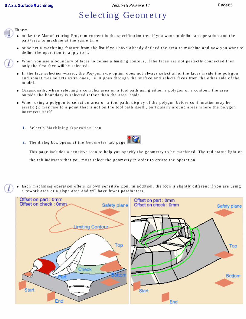
1. Select a Machining Operation icon.
2. The dialog box opens at the Geometry tab page .
This page includes a sensitive icon to help you specify the geometry to be machined. The red status light on
the tab indicates that you must select the geometry in order to create the operation
● Each machining operation offers its own sensitive icon. In addition, the icon is slightly different if you are using a rework area or a slope area and will have fewer parameters.
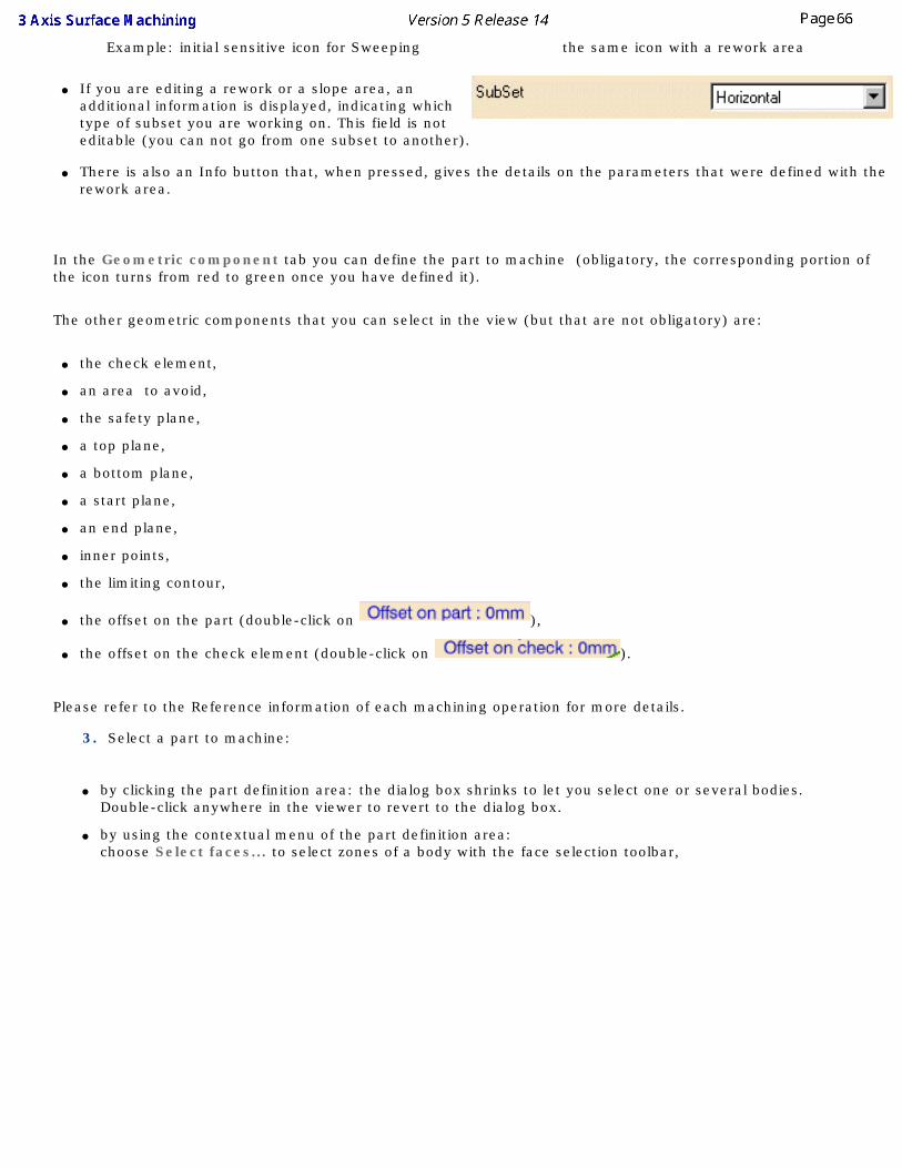
Example: initial sensitive icon for Sweeping the same icon with a rework area
● If you are editing a rework or a slope area, an additional information is displayed, indicating which type of subset you are working on. This field is not editable (you can not go from one subset to another).
● There is also an Info button that, when pressed, gives the details on the parameters that were defined with the rework area.
In the Geometric component tab you can define the part to machine (obligatory, the corresponding portion of the icon turns from red to green once you have defined it).
The other geometric components that you can select in the view (but that are not obligatory) are:
● the check element,
● an area to avoid,
● the safety plane,
● a top plane,
● a bottom plane,
● a start plane,
● an end plane,
● inner points,
● the limiting contour,
● the offset on the part (double-click on ),
● the offset on the check element (double-click on ).
Please refer to the Reference information of each machining operation for more details.
3. Select a part to machine:
● by clicking the part definition area: the dialog box shrinks to let you select one or several bodies. Double-click anywhere in the viewer to revert to the dialog box.
● by using the contextual menu of the part definition area: choose Select faces... to select zones of a body with the face selection toolbar,
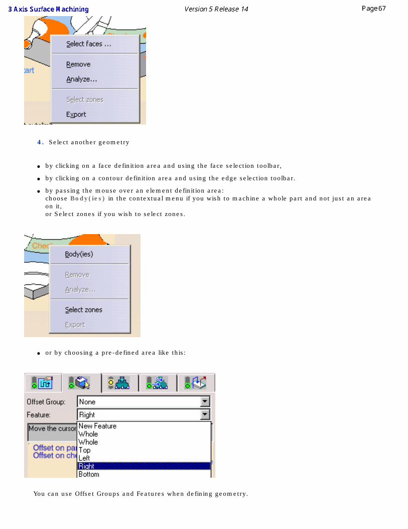
4. Select another geometry
● by clicking on a face definition area and using the face selection toolbar,
● by clicking on a contour definition area and using the edge selection toolbar.
● by passing the mouse over an element definition area: choose Body(ies) in the contextual menu if you wish to machine a whole part and not just an area on it, or Select zones if you wish to select zones.
● or by choosing a pre-defined area like this:
You can use Offset Groups and Features when defining geometry.
● The types of selection by default (reached by clicking a sensitive zone) are adapted to the types of the elements to select (bodies for a part to machine, but faces for check elements, for instance).
● The contextual menus vary also with the type of elements to select.
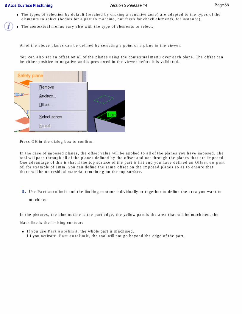
All of the above planes can be defined by selecting a point or a plane in the viewer.
You can also set an offset on all of the planes using the contextual menu over each plane. The offset can be either positive or negative and is previewed in the viewer before it is validated.
Press OK in the dialog box to confirm.
In the case of imposed planes, the offset value will be applied to all of the planes you have imposed. The tool will pass through all of the planes defined by the offset and not through the planes that are imposed. One advantage of this is that if the top surface of the part is flat and you have defined an Offset on part of, for example of 1mm, you can define the same offset on the imposed planes so as to ensure that there will be no residual material remaining on the top surface.
5. Use Part autolimit and the limiting contour individually or together to define the area you want to
machine:
In the pictures, the blue outline is the part edge, the yellow part is the area that will be machined, the
black line is the limiting contour:
● If you use Part autolimit, the whole part is machined. I f you activate Part autolimit, the tool will not go beyond the edge of the part.
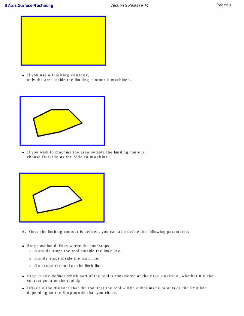
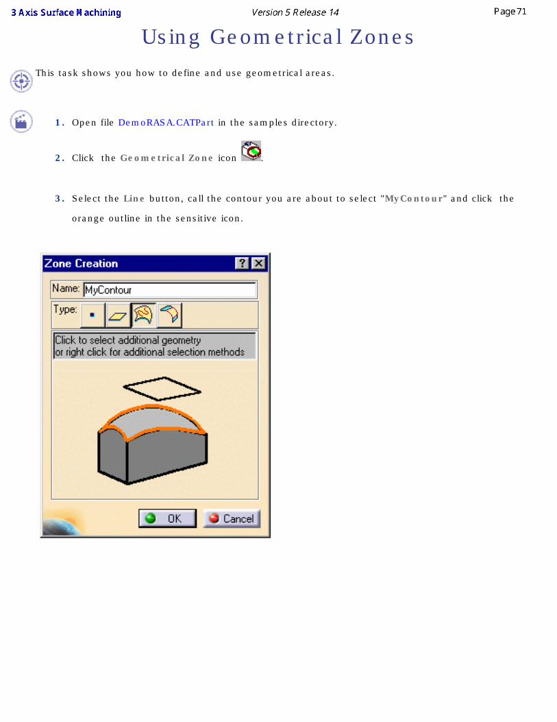
● If you use a Limiting contour, only the area inside the limiting contour is machined.
● If you wish to machine the area outside the limiting contour, choose Outside as the Side to machine.
6. Once the limiting contour is defined, you can also define the following parameters:
● Stop position defines where the tool stops: ❍ Outside stops the tool outside the limit line,
❍ Inside stops inside the limit line,
❍ On stops the tool on the limit line.
● Stop mode defines which part of the tool is considered at the Stop position, whether it is the contact point or the tool tip.
● Offset is the distance that the tool that the tool will be either inside or outside the limit line depending on the Stop mode that you chose.

You can now either run the operation on the part, store the operation that you have just defined or define other parameters in the machining strategy, tool data, speeds and rates, or macro data tabs first.
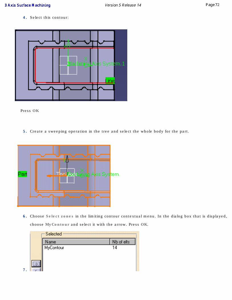
Using Geometrical Zones This task shows you how to define and use geometrical areas.
1. Open file DemoRASA.CATPart in the samples directory.
2. Click the Geometrical Zone icon .
3. Select the Line button, call the contour you are about to select "MyContour" and click the
orange outline in the sensitive icon.
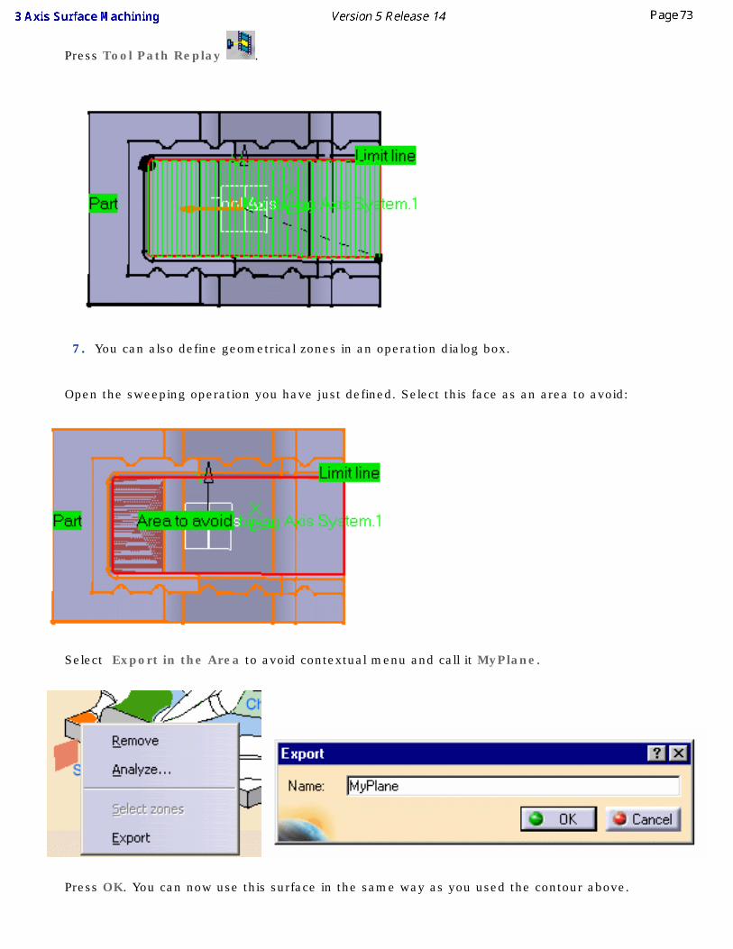
4. Select this contour:
Press OK
5. Create a sweeping operation in the tree and select the whole body for the part.
6. Choose Select zones in the limiting contour contextual menu. In the dialog box that is displayed,
choose MyContour and select it with the arrow. Press OK.
7.
Press Tool Path Replay .
7. You can also define geometrical zones in an operation dialog box.
Open the sweeping operation you have just defined. Select this face as an area to avoid:
Select Export in the Area to avoid contextual menu and call it MyPlane.
Press OK. You can now use this surface in the same way as you used the contour above.

● All geometrical zones that you create can be used in any number of operations.
● The Hide/Show item in the contextual menu does not work for geometrical zones .
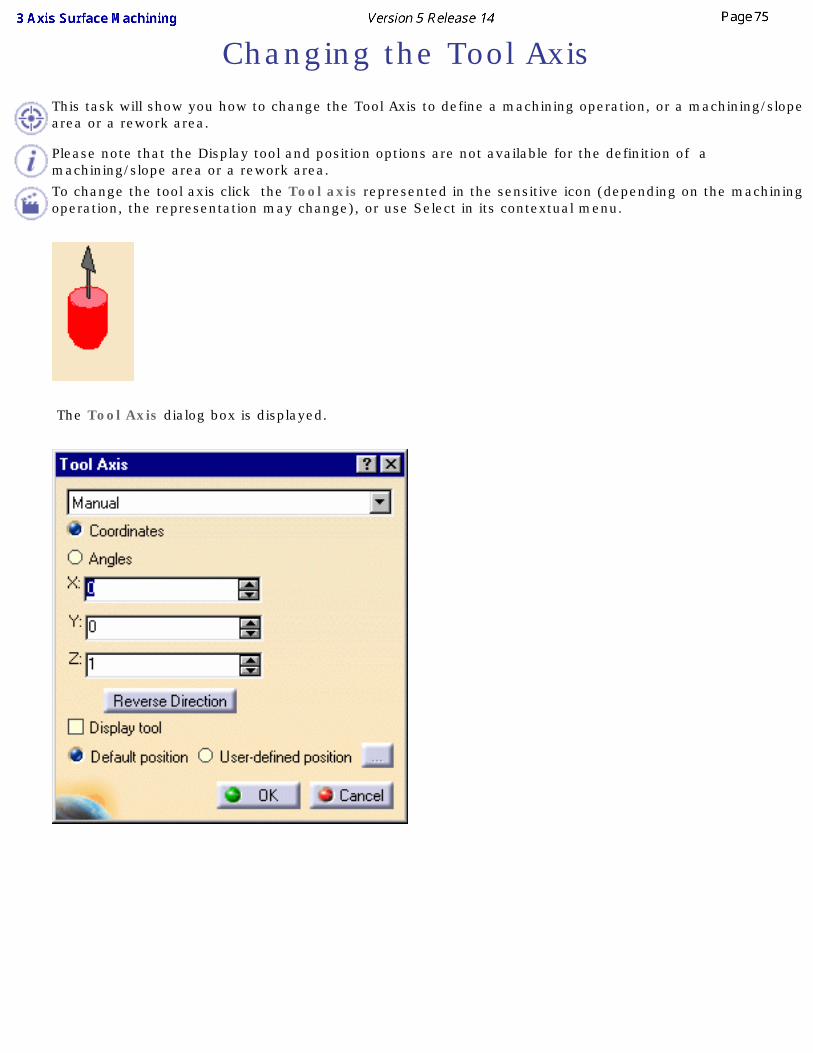
Changing the Tool AxisThis task will show you how to change the Tool Axis to define a machining operation, or a machining/slope area or a rework area.
Please note that the Display tool and position options are not available for the definition of a machining/slope area or a rework area.
To change the tool axis click the Tool axis represented in the sensitive icon (depending on the machining operation, the representation may change), or use Select in its contextual menu.
The Tool Axis dialog box is displayed.
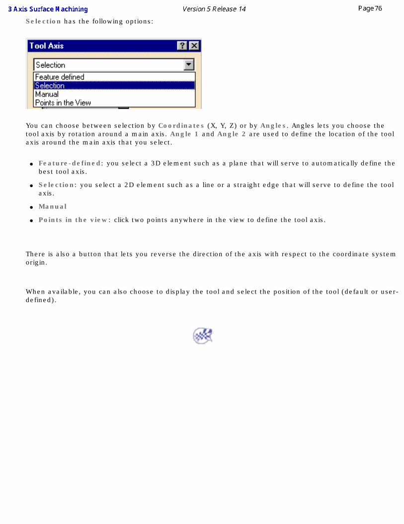
Selection has the following options:
You can choose between selection by Coordinates (X, Y, Z) or by Angles. Angles lets you choose the tool axis by rotation around a main axis. Angle 1 and Angle 2 are used to define the location of the tool axis around the main axis that you select.
● Feature-defined: you select a 3D element such as a plane that will serve to automatically define the best tool axis.
● Selection: you select a 2D element such as a line or a straight edge that will serve to define the tool axis.
● Manual
● Points in the view: click two points anywhere in the view to define the tool axis.
There is also a button that lets you reverse the direction of the axis with respect to the coordinate system origin.
When available, you can also choose to display the tool and select the position of the tool (default or user-defined).
Compute Tool Gage on Assembly
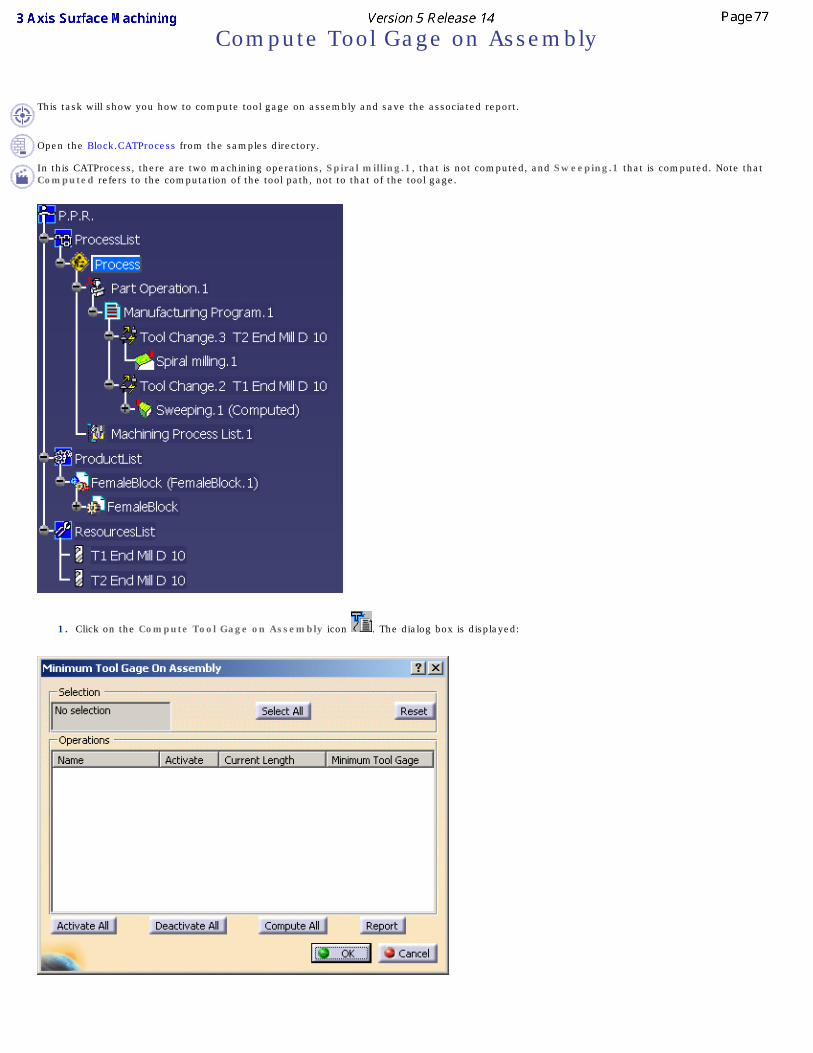
This task will show you how to compute tool gage on assembly and save the associated report.
Open the Block.CATProcess from the samples directory.
In this CATProcess, there are two machining operations, Spiral milling.1, that is not computed, and Sweeping.1 that is computed. Note that Computed refers to the computation of the tool path, not to that of the tool gage.
1. Click on the Compute Tool Gage on Assembly icon . The dialog box is displayed:
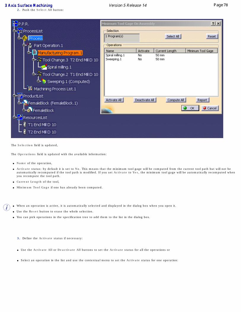
2. Push the Select All button:
The Selection field is updated,
The Operations field is updated with the available information:
● Name of the operation,
● Activate status: by default it is set to No. This means that the minimum tool gage will be computed from the current tool path but will not be automatically recomputed if the tool path is modified. If you set Activate to Yes, the minimum tool gage will be automatically recomputed when you recompute the tool path.
● Current Length of the tool,
● Minimum Tool Gage if one has already been computed.
● When an operation is active, it is automatically selected and displayed in the dialog box when you open it.
● Use the Reset button to erase the whole selection.
● You can pick operations in the specification tree to add them to the list in the dialog box.
3. Define the Activate status if necessary:
● Use the Activate All or Deactivate All buttons to set the Activate status for all the operations or
● Select an operation in the list and use the contextual menu to set the Activate status for one operation:
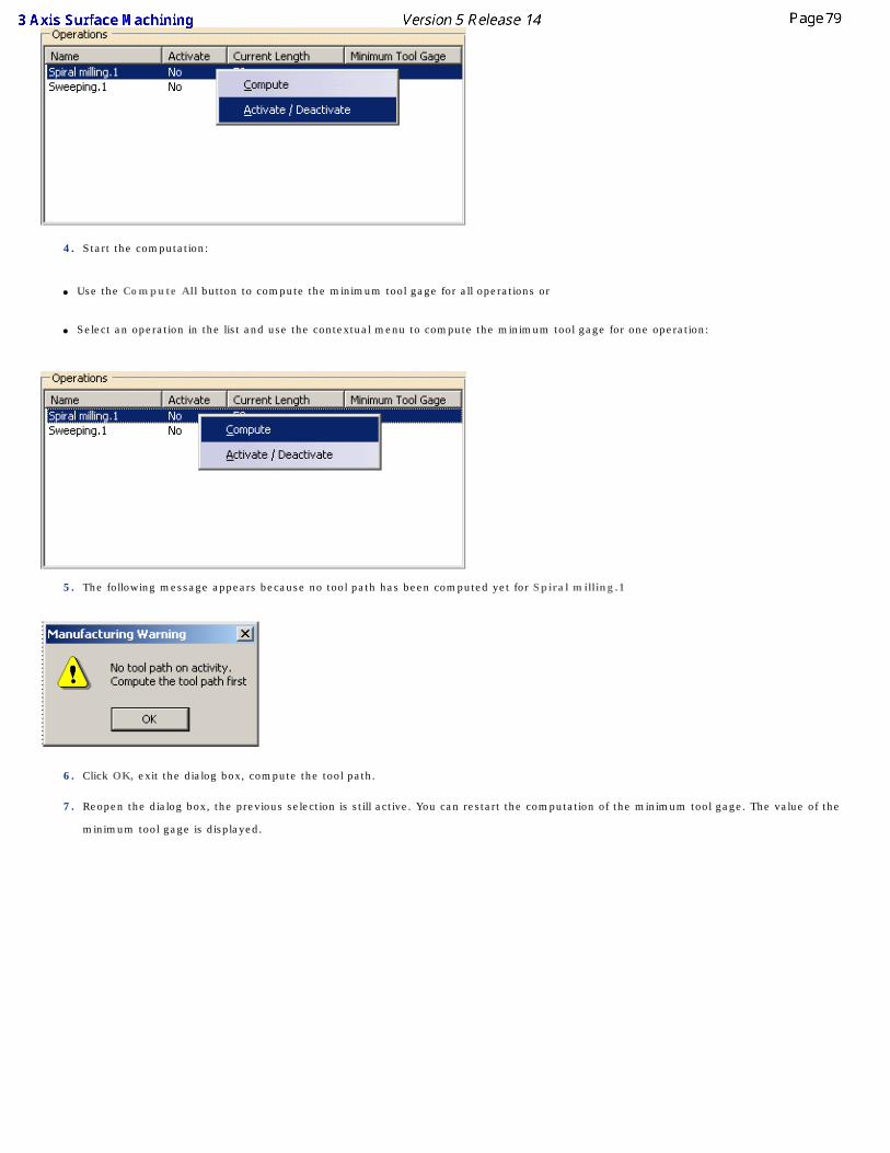
4. Start the computation:
● Use the Compute All button to compute the minimum tool gage for all operations or
● Select an operation in the list and use the contextual menu to compute the minimum tool gage for one operation:
5. The following message appears because no tool path has been computed yet for Spiral milling.1
6. Click OK, exit the dialog box, compute the tool path.
7. Reopen the dialog box, the previous selection is still active. You can restart the computation of the minimum tool gage. The value of the
minimum tool gage is displayed.
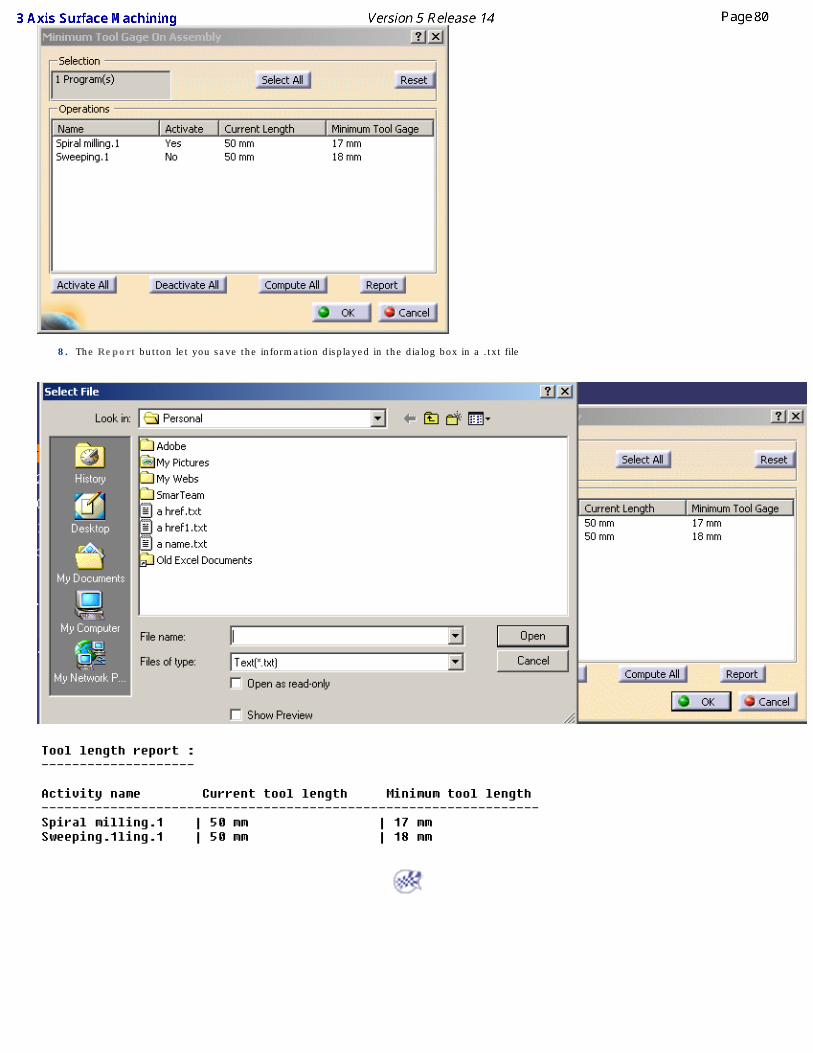
8. The Report button let you save the information displayed in the dialog box in a .txt file
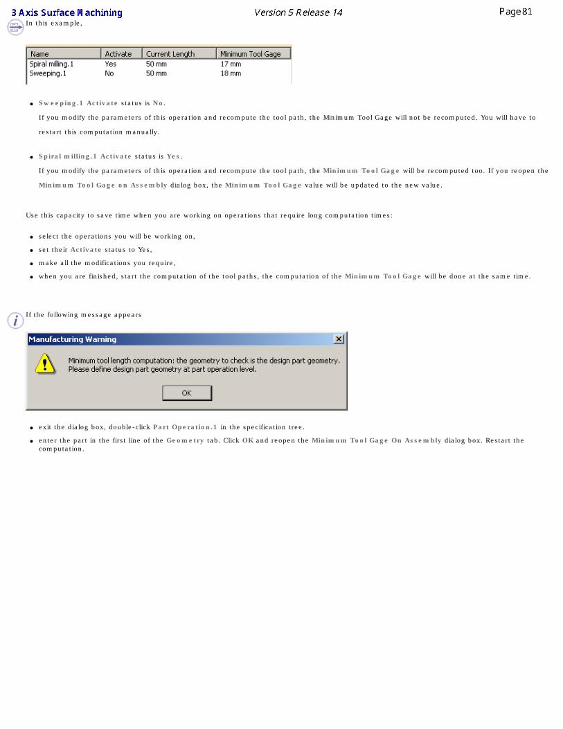
In this example,
● Sweeping.1 Activate status is No.
If you modify the parameters of this operation and recompute the tool path, the Minimum Tool Gage will not be recomputed. You will have to
restart this computation manually.
● Spiral milling.1 Activate status is Yes.
If you modify the parameters of this operation and recompute the tool path, the Minimum Tool Gage will be recomputed too. If you reopen the
Minimum Tool Gage on Assembly dialog box, the Minimum Tool Gage value will be updated to the new value.
Use this capacity to save time when you are working on operations that require long computation times:
● select the operations you will be working on,
● set their Activate status to Yes,
● make all the modifications you require,
● when you are finished, start the computation of the tool paths, the computation of the Minimum Tool Gage will be done at the same time.
If the following message appears
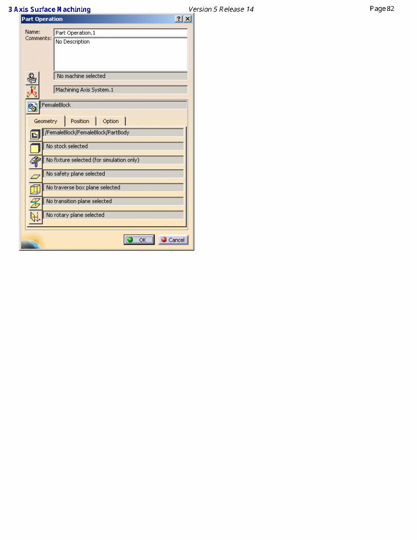
● exit the dialog box, double-click Part Operation.1 in the specification tree.
● enter the part in the first line of the Geometry tab. Click OK and reopen the Minimum Tool Gage On Assembly dialog box. Restart the computation.
Rough Machining OperationsThese are the tasks that you will use for rough machining the part.
Create a sweep roughing operation: ● Select the sweep roughing icon,
● Choose a part to machine,
● Specify the tool to be used.
You can also specify machining parameters, feedrates and spindle speeds and macro data.
Create a roughing operation:
● Select the roughing icon,
● Choose a part to machine
● Specify the tool to be used,
● Specify the type of roughing.
You can also specify machining parameters, feedrates and spindle speeds and macro data.
Basic tasks illustrate:
● a sweep roughing operation,
● a roughing operation,
● ordering zones in a roughing operation,
● the creation of an automatic rough stock,
● the creation of an offset on part.
Sweep RoughingThis task shows you how to insert a sweep roughing operation into the program. Sweep roughing is an operation which allows you to rough machine parts by vertical planes.
To create the operation you define:
● the geometry of the part to machine ,
● the parameters of the machining strategy ,
● the tool to use ;only end mill tools are available for this operation,
● the feedrates and spindle speeds ,
● the macros. .
Only the geometry is obligatory, all of the other requirements have a default value.
Either:
● make the Manufacturing Program current in the specification tree if you want to define an operation and the part/area to machine at the same time,
● or select a machining feature from the list if you have already defined the area to machine and now you want to define the operation to apply to it.
Below we are going to see how to do the first of these.
Open file Basic1.CATPart then select Machining > Surface Machining in the Start menu.
1. Select the Sweep Roughing icon .
A SweepRoughing entity and a default tool are added to the program. The dialog box opens
at the geometry tab page . This page includes a sensitive icon to help you specify the geometry to be machined.
The area that represents the part geometry is colored red indicating that the geometry is required for defining the area to machine. All of the other geometry parameters are optional.
2. Click the red area in the sensitive icon and select the part in the viewer.
Then double click anywhere in the viewer to confirm your selection and redisplay the dialog box.
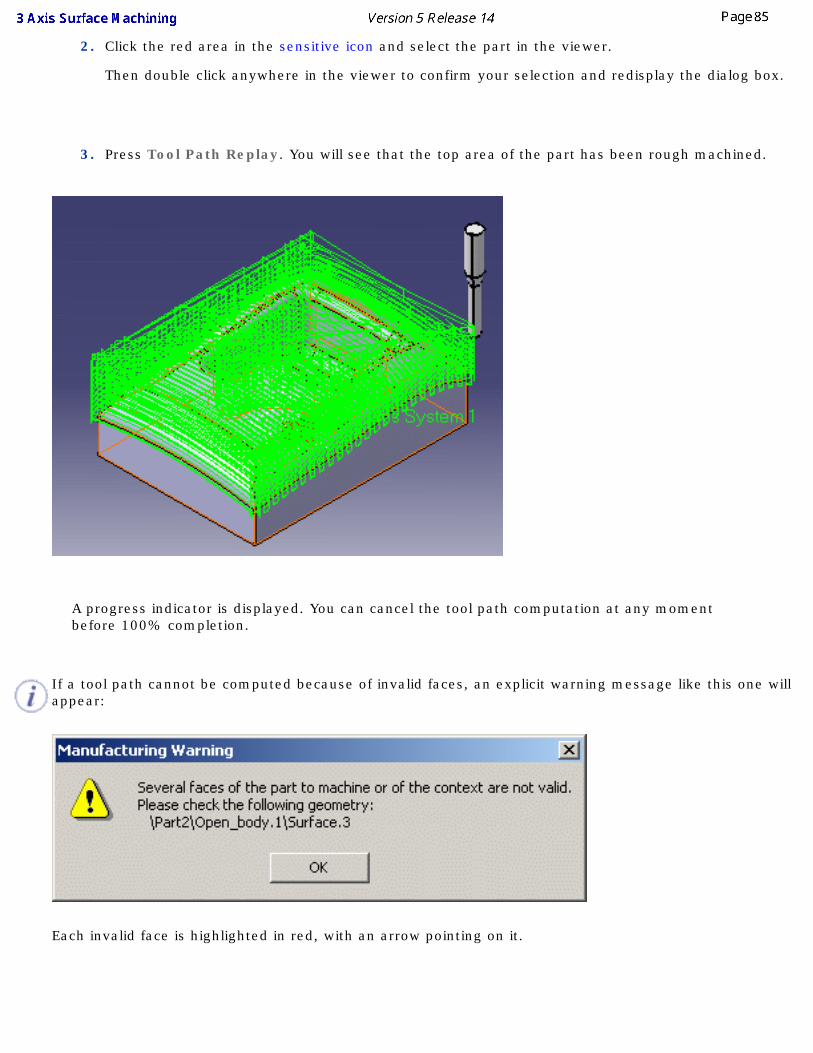
3. Press Tool Path Replay. You will see that the top area of the part has been rough machined.
A progress indicator is displayed. You can cancel the tool path computation at any moment before 100% completion.
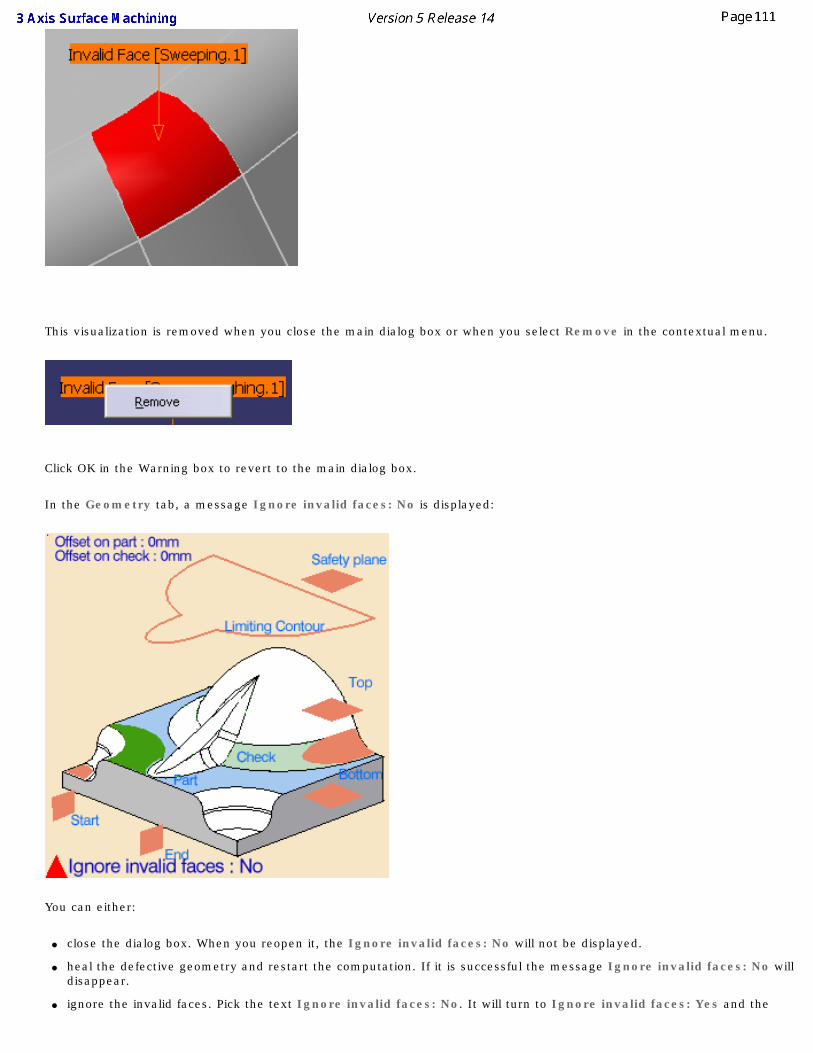
If a tool path cannot be computed because of invalid faces, an explicit warning message like this one will appear:
Each invalid face is highlighted in red, with an arrow pointing on it.
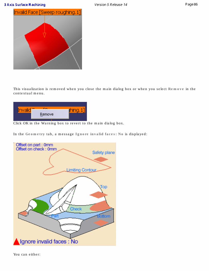
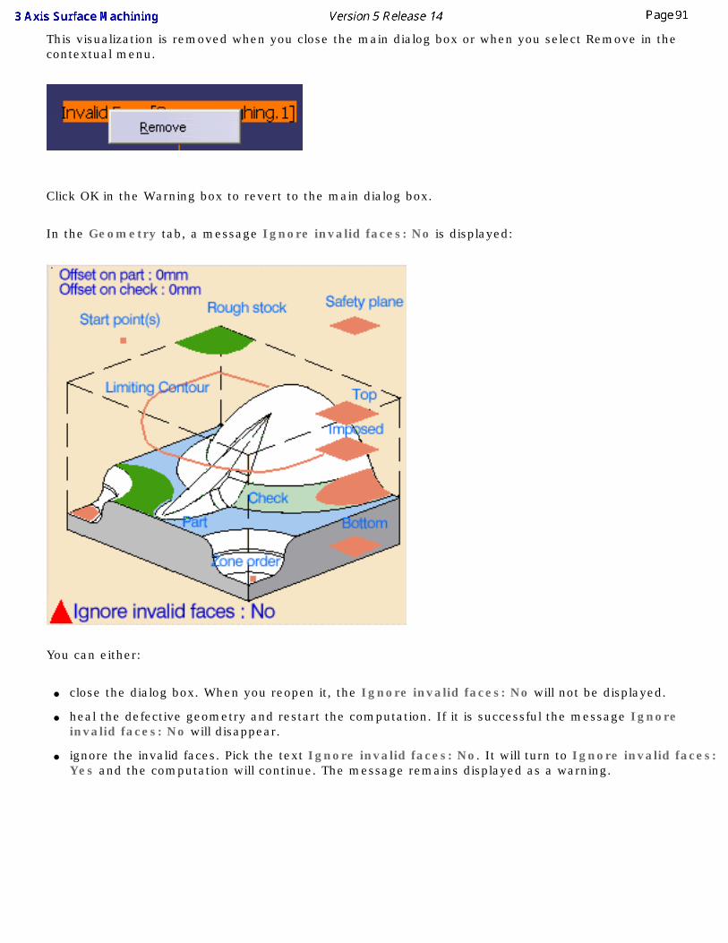
This visualization is removed when you close the main dialog box or when you select Remove in the contextual menu.
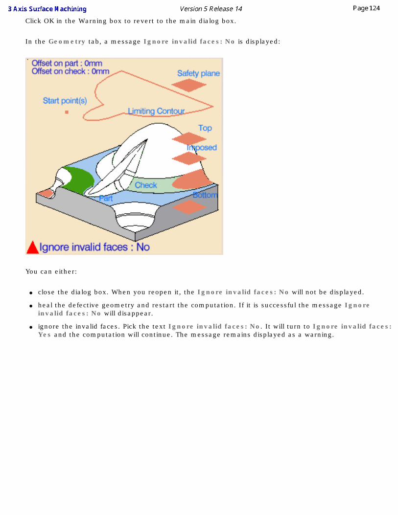
Click OK in the Warning box to revert to the main dialog box.
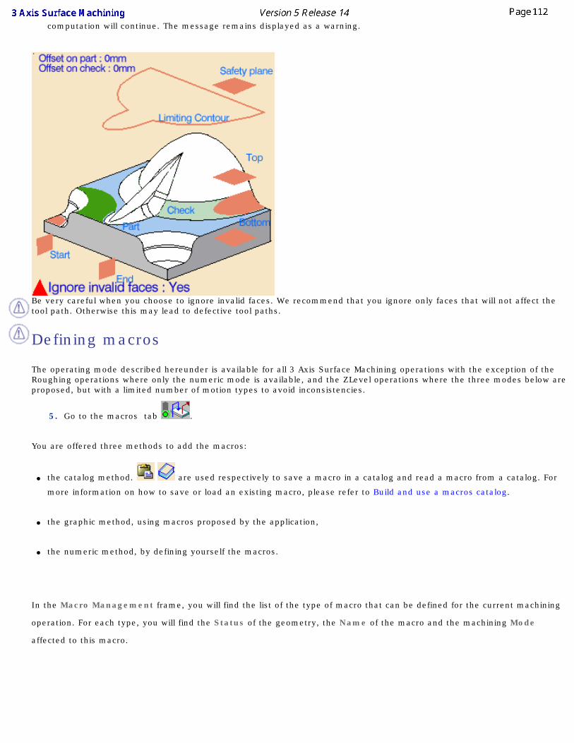
In the Geometry tab, a message Ignore invalid faces: No is displayed:
You can either:
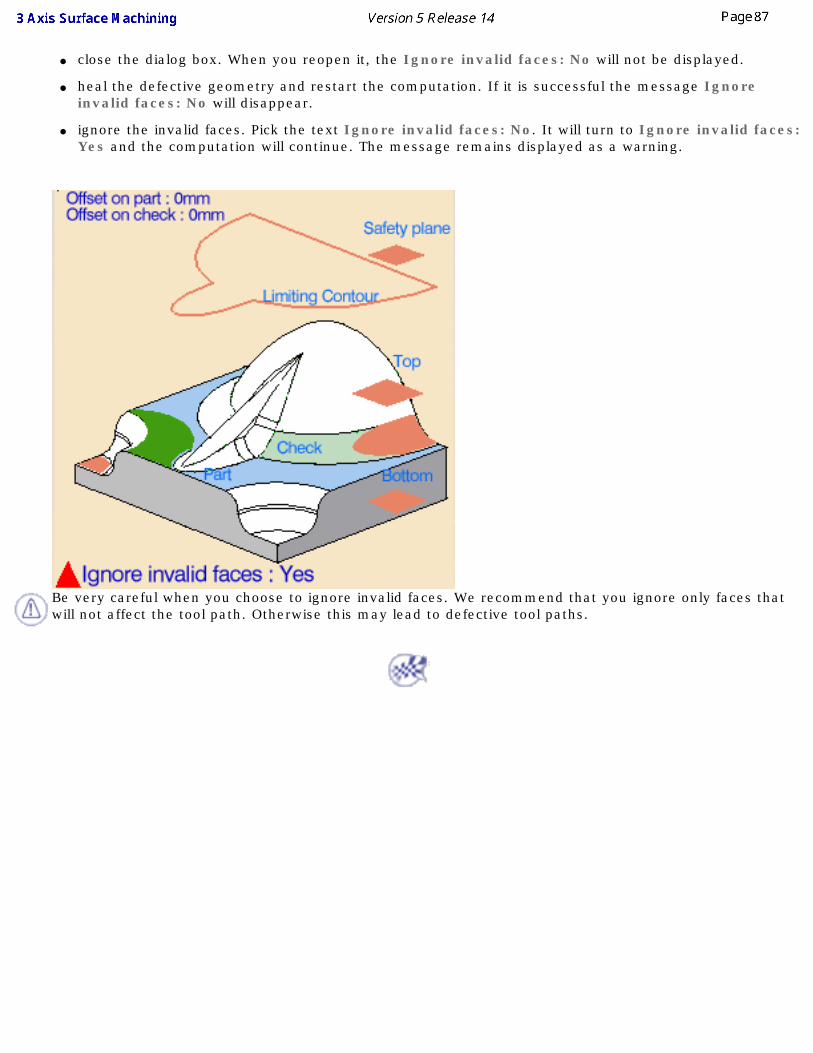
● close the dialog box. When you reopen it, the Ignore invalid faces: No will not be displayed.
● heal the defective geometry and restart the computation. If it is successful the message Ignore invalid faces: No will disappear.
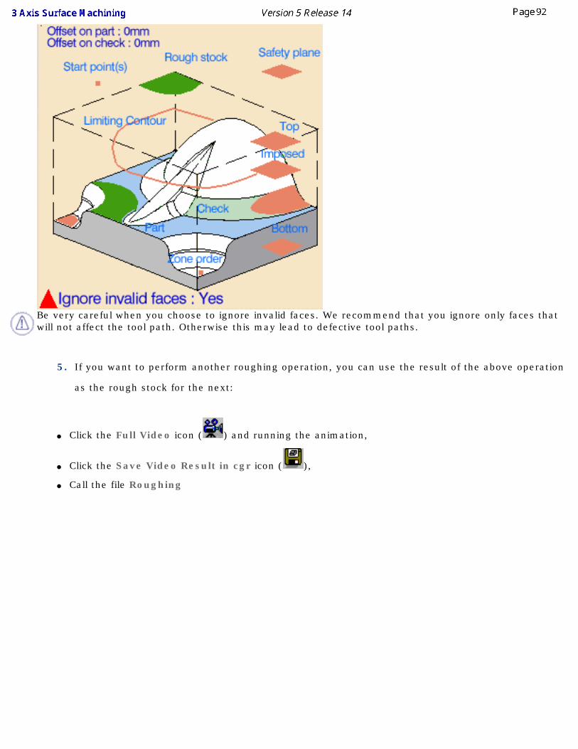
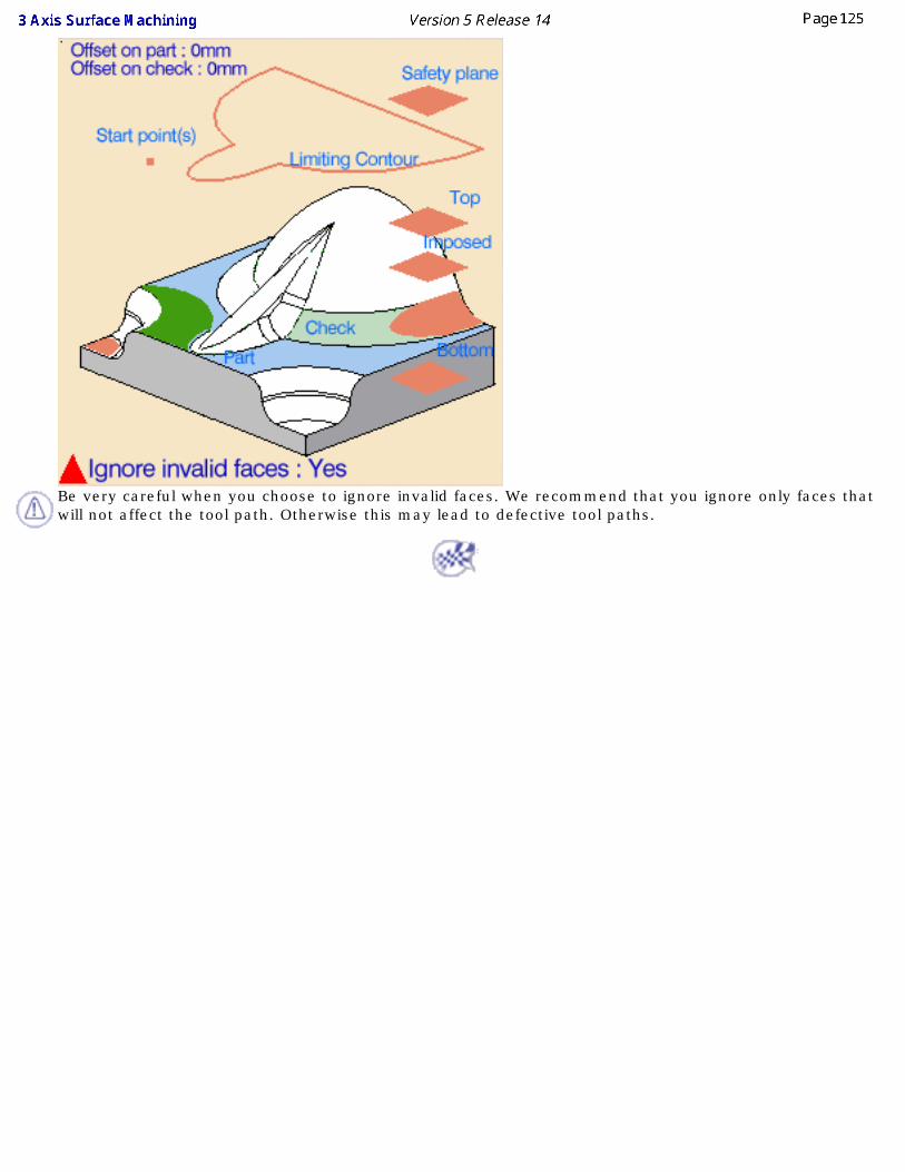
● ignore the invalid faces. Pick the text Ignore invalid faces: No. It will turn to Ignore invalid faces: Yes and the computation will continue. The message remains displayed as a warning.
Be very careful when you choose to ignore invalid faces. We recommend that you ignore only faces that will not affect the tool path. Otherwise this may lead to defective tool paths.
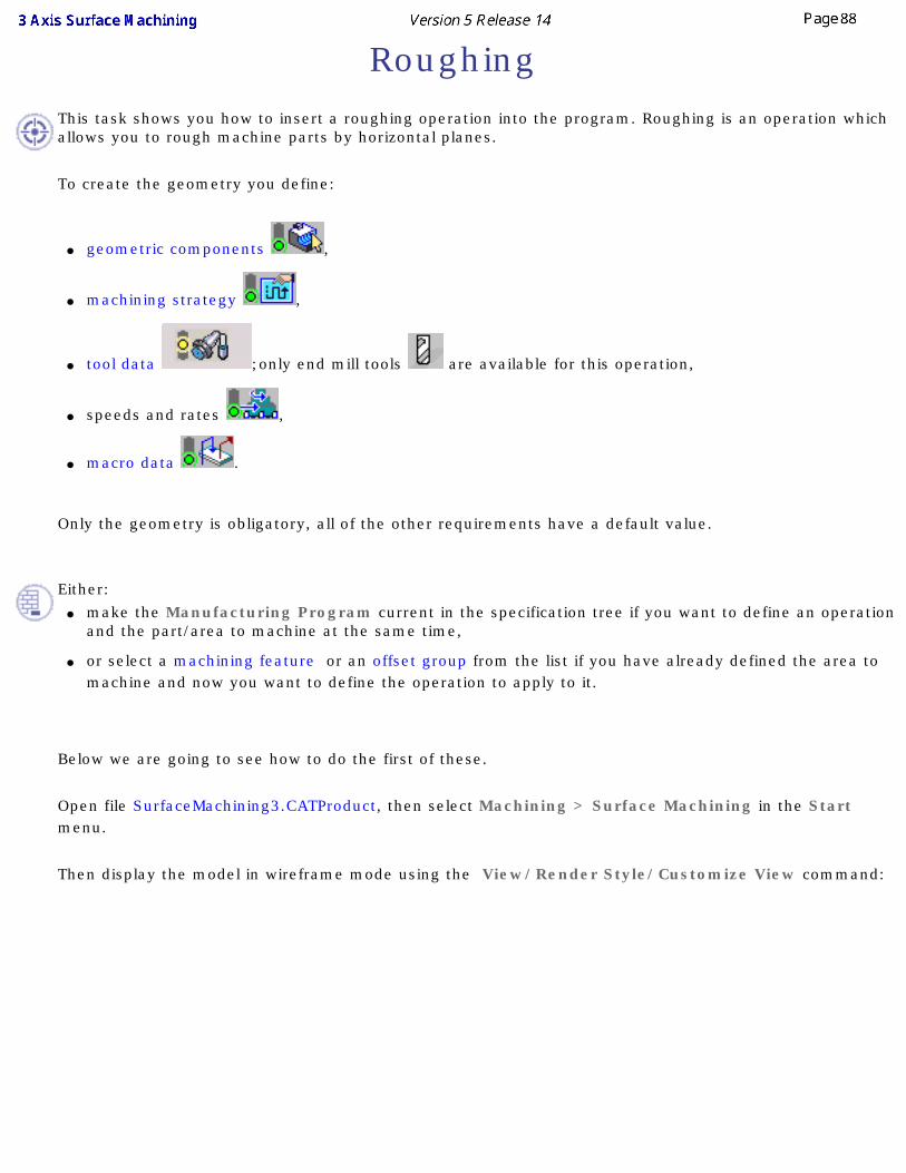
RoughingThis task shows you how to insert a roughing operation into the program. Roughing is an operation which allows you to rough machine parts by horizontal planes.
To create the geometry you define:
● geometric components ,
● machining strategy ,
● tool data ;only end mill tools are available for this operation,
● speeds and rates ,
● macro data .
Only the geometry is obligatory, all of the other requirements have a default value.
Either:
● make the Manufacturing Program current in the specification tree if you want to define an operation and the part/area to machine at the same time,
● or select a machining feature or an offset group from the list if you have already defined the area to machine and now you want to define the operation to apply to it.
Below we are going to see how to do the first of these.
Open file SurfaceMachining3.CATProduct, then select Machining > Surface Machining in the Start menu.
Then display the model in wireframe mode using the View/Render Style/Customize View command:
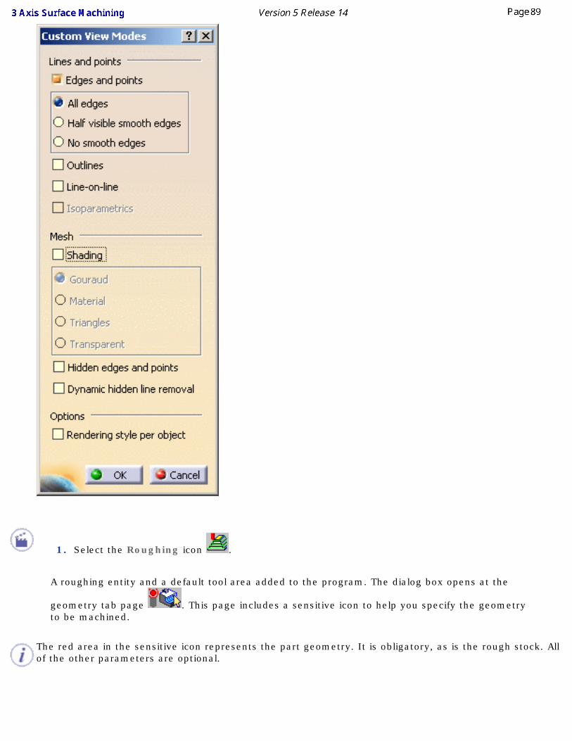
1. Select the Roughing icon .
A roughing entity and a default tool area added to the program. The dialog box opens at the
geometry tab page . This page includes a sensitive icon to help you specify the geometry to be machined.
The red area in the sensitive icon represents the part geometry. It is obligatory, as is the rough stock. All of the other parameters are optional.
2. Click the red area in the sensitive icon and select the part in the viewer. Then double click
anywhere in the viewer to confirm your selection and redisplay the dialog box.
3. Click the rough stock in the sensitive icon.
Select the stock in the viewer.
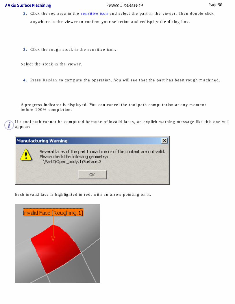
4. Press Replay to compute the operation. You will see that the part has been rough machined.
A progress indicator is displayed. You can cancel the tool path computation at any moment before 100% completion.
If a tool path cannot be computed because of invalid faces, an explicit warning message like this one will appear:
Each invalid face is highlighted in red, with an arrow pointing on it.
This visualization is removed when you close the main dialog box or when you select Remove in the contextual menu.
Click OK in the Warning box to revert to the main dialog box.
In the Geometry tab, a message Ignore invalid faces: No is displayed:
You can either:
● close the dialog box. When you reopen it, the Ignore invalid faces: No will not be displayed.
● heal the defective geometry and restart the computation. If it is successful the message Ignore invalid faces: No will disappear.
● ignore the invalid faces. Pick the text Ignore invalid faces: No. It will turn to Ignore invalid faces: Yes and the computation will continue. The message remains displayed as a warning.
Be very careful when you choose to ignore invalid faces. We recommend that you ignore only faces that will not affect the tool path. Otherwise this may lead to defective tool paths.
5. If you want to perform another roughing operation, you can use the result of the above operation
as the rough stock for the next:
● Click the Full Video icon ( ) and running the animation,
● Click the Save Video Result in cgr icon ( ),
● Call the file Roughing
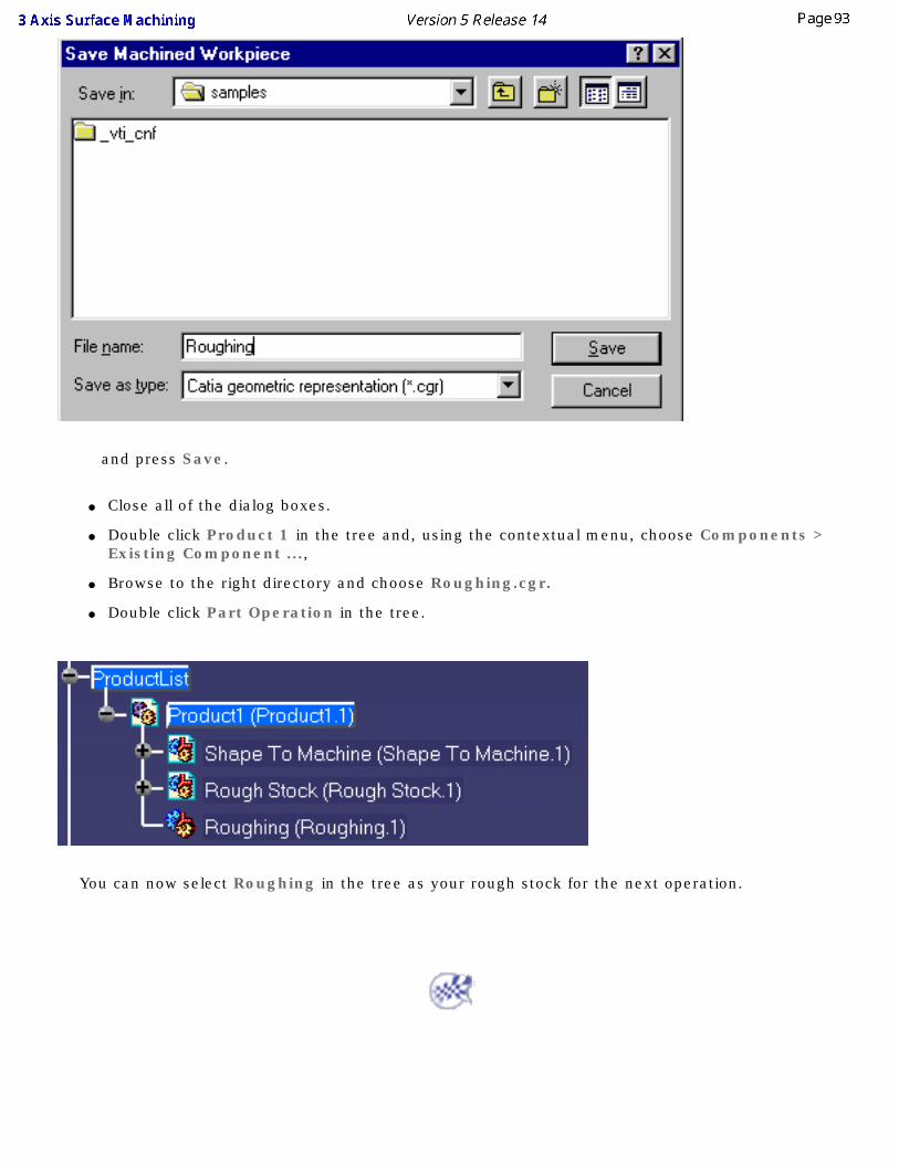
and press Save.
● Close all of the dialog boxes.
● Double click Product 1 in the tree and, using the contextual menu, choose Components > Existing Component ...,
● Browse to the right directory and choose Roughing.cgr.
● Double click Part Operation in the tree.
You can now select Roughing in the tree as your rough stock for the next operation.
Roughing - Ordering Zones
This task will show you how to set the order in which the zones on a part are machined. Zones can be either pockets or the outer part.
You must have a part that has a point or a plane defined in the each of the zones you want to select.
1. Open ZoneOrder.CATProcess from the samples directory.
2. Click the Roughing icon .
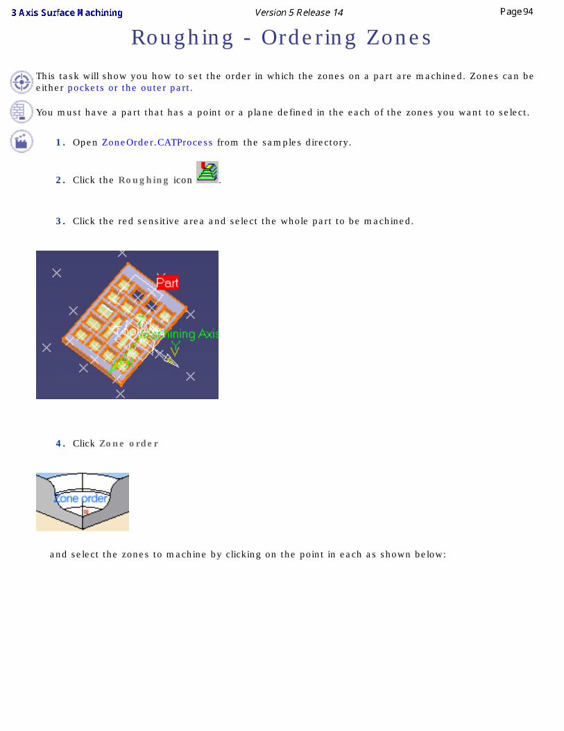
3. Click the red sensitive area and select the whole part to be machined.
4. Click Zone order
and select the zones to machine by clicking on the point in each as shown below:
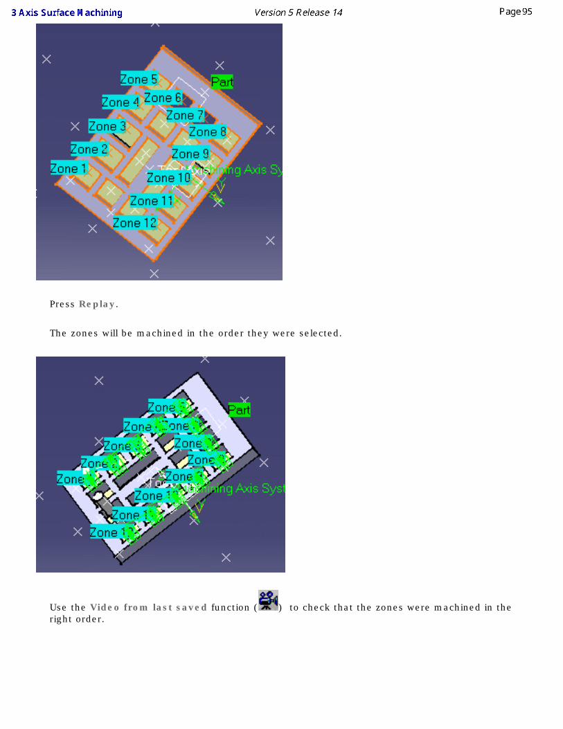
Press Replay.
The zones will be machined in the order they were selected.
Use the Video from last saved function ( ) to check that the zones were machined in the right order.
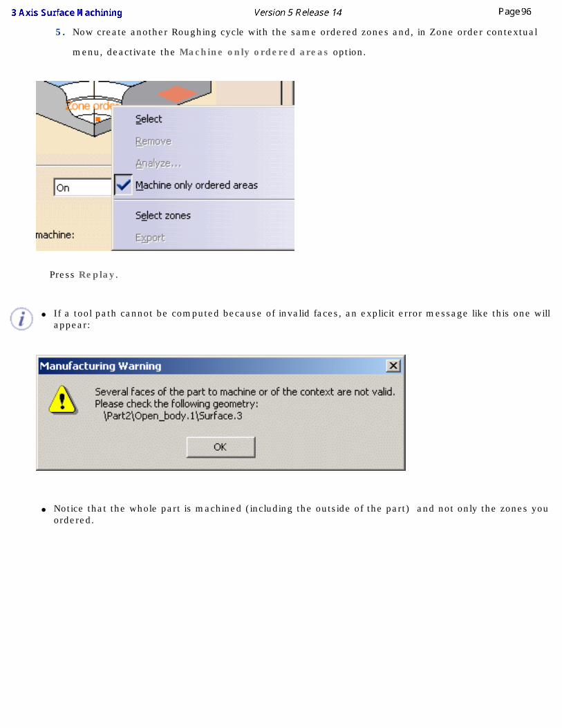
5. Now create another Roughing cycle with the same ordered zones and, in Zone order contextual
menu, deactivate the Machine only ordered areas option.
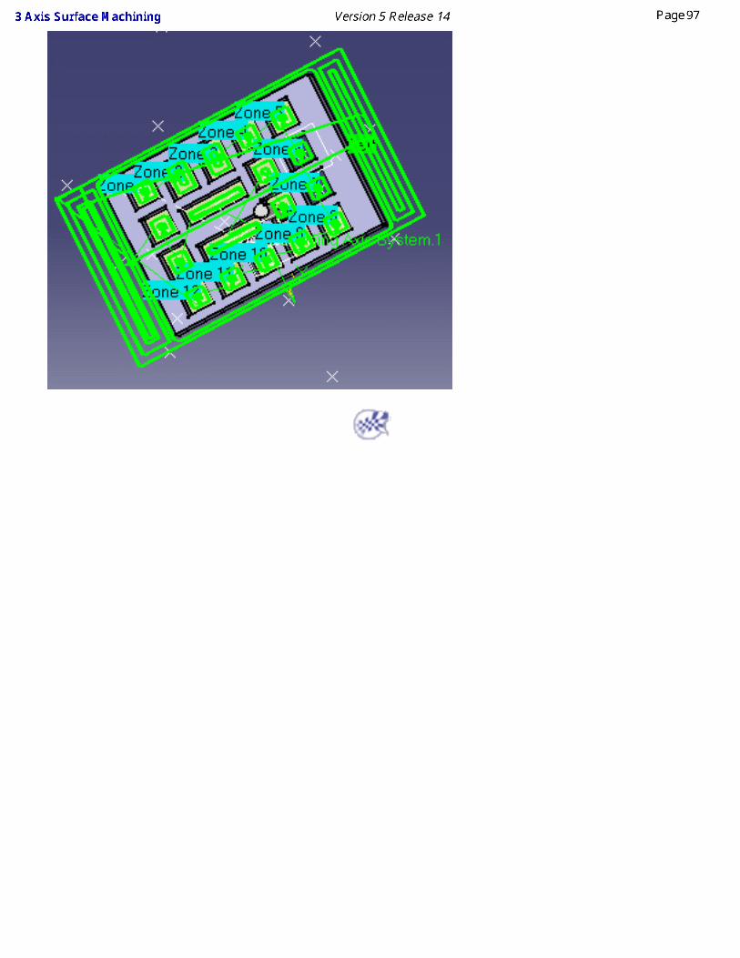
Press Replay.
● If a tool path cannot be computed because of invalid faces, an explicit error message like this one will appear:
● Notice that the whole part is machined (including the outside of the part) and not only the zones you ordered.
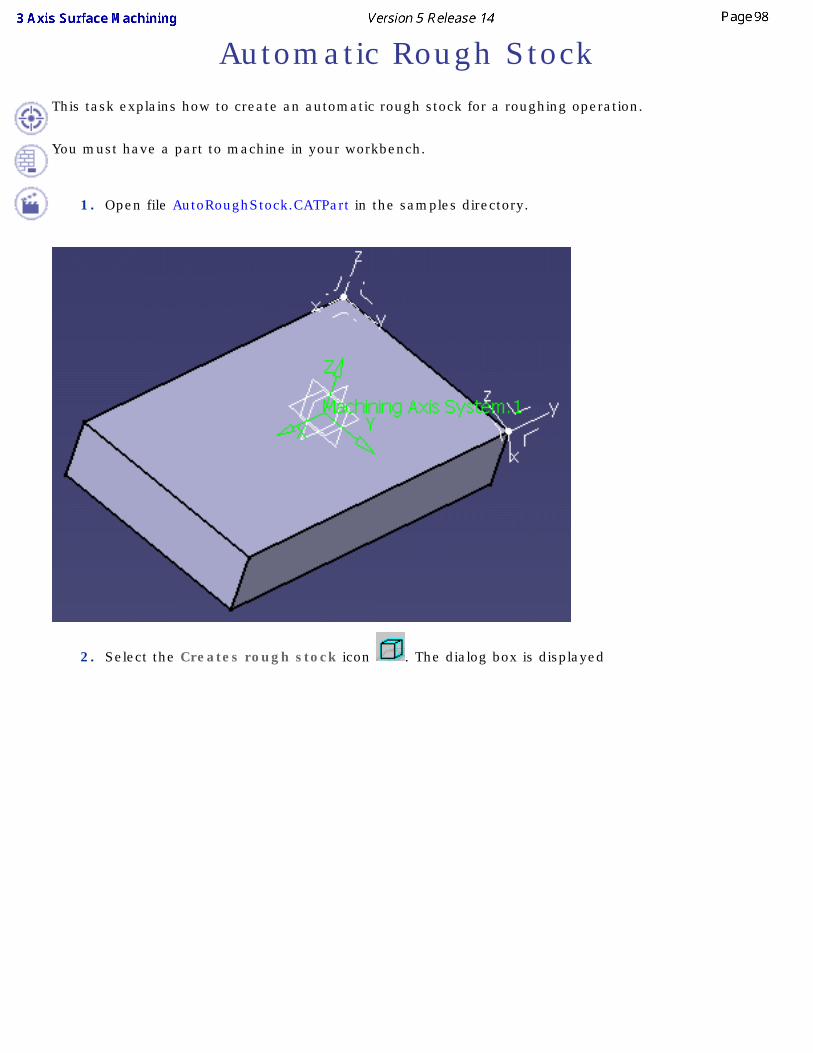
Automatic Rough StockThis task explains how to create an automatic rough stock for a roughing operation.
You must have a part to machine in your workbench.
1. Open file AutoRoughStock.CATPart in the samples directory.
2. Select the Creates rough stock icon . The dialog box is displayed
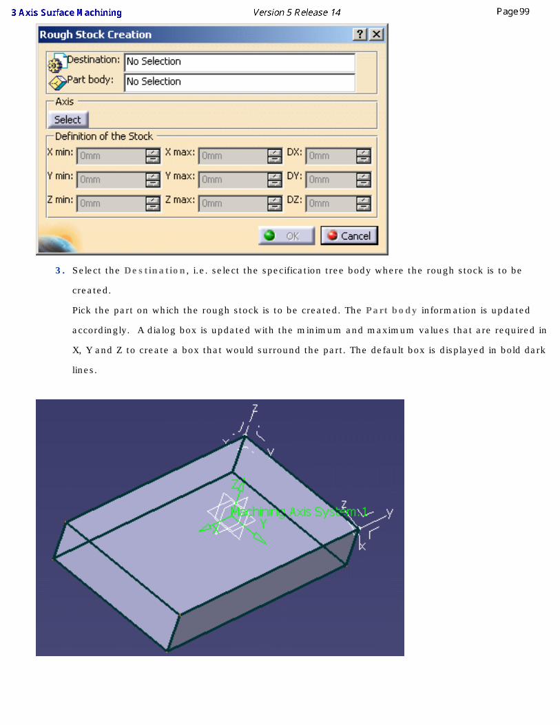
3. Select the Destination, i.e. select the specification tree body where the rough stock is to be
created.
Pick the part on which the rough stock is to be created. The Part body information is updated
accordingly. A dialog box is updated with the minimum and maximum values that are required in
X, Y and Z to create a box that would surround the part. The default box is displayed in bold dark
lines.
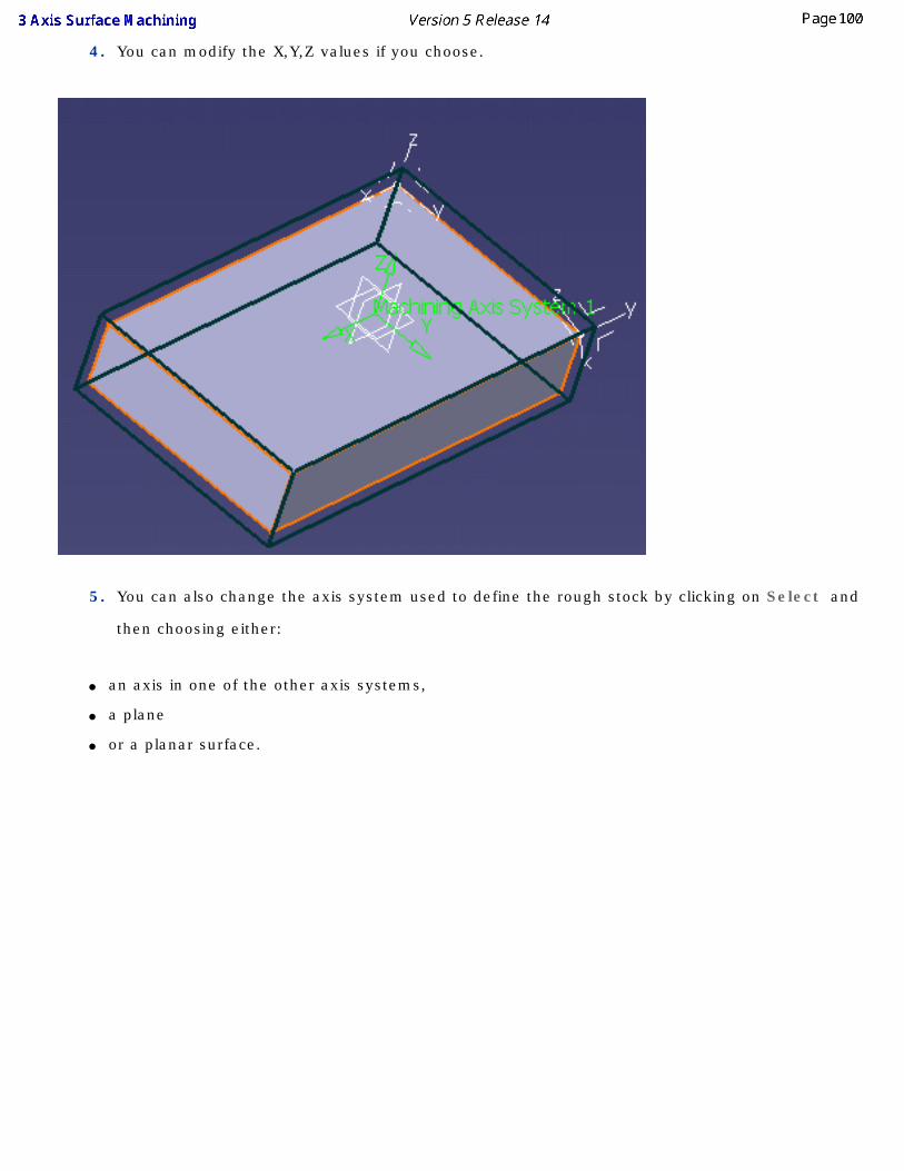
4. You can modify the X,Y,Z values if you choose.
5. You can also change the axis system used to define the rough stock by clicking on Select and
then choosing either:
● an axis in one of the other axis systems,
● a plane
● or a planar surface.
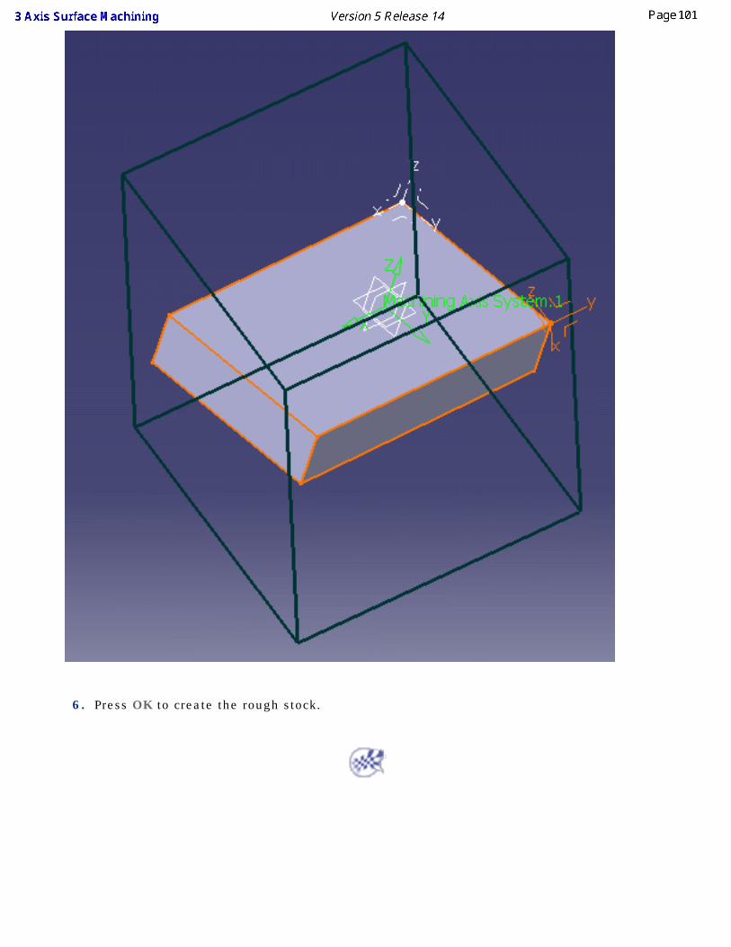
6. Press OK to create the rough stock.
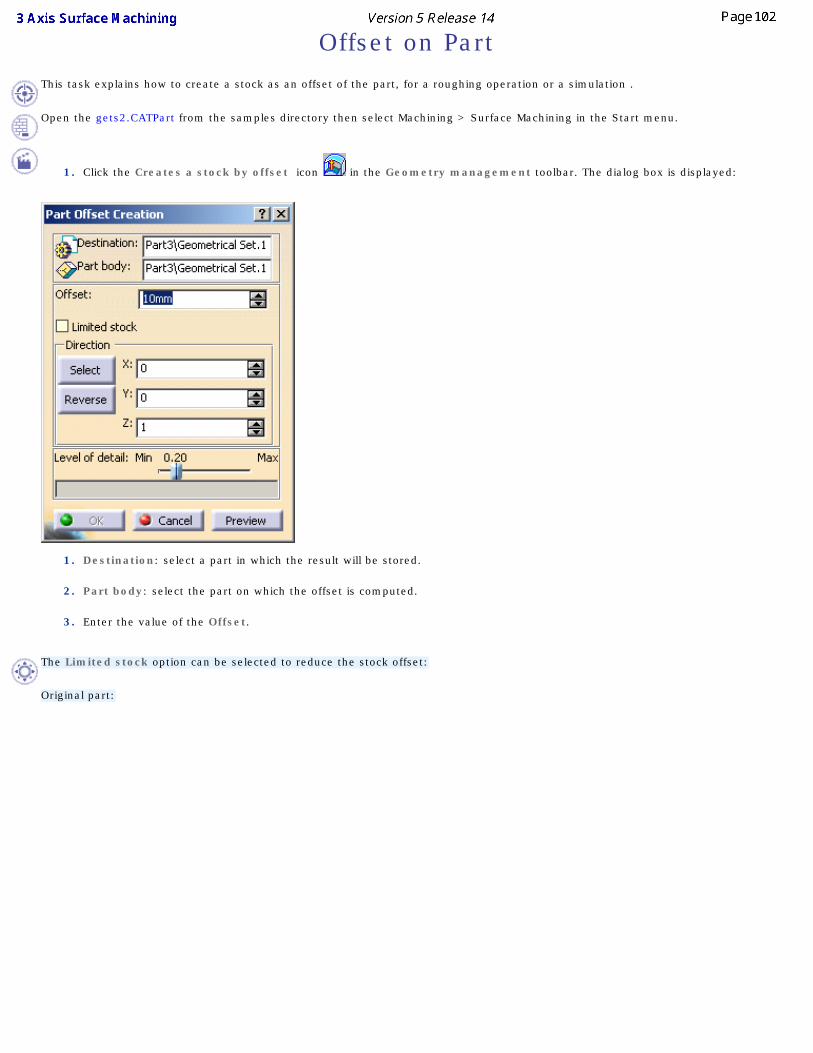
Offset on PartThis task explains how to create a stock as an offset of the part, for a roughing operation or a simulation .
Open the gets2.CATPart from the samples directory then select Machining > Surface Machining in the Start menu.
1. Click the Creates a stock by offset icon in the Geometry management toolbar. The dialog box is displayed:
1. Destination: select a part in which the result will be stored.
2. Part body: select the part on which the offset is computed.
3. Enter the value of the Offset.
The Limited stock option can be selected to reduce the stock offset:
Original part:
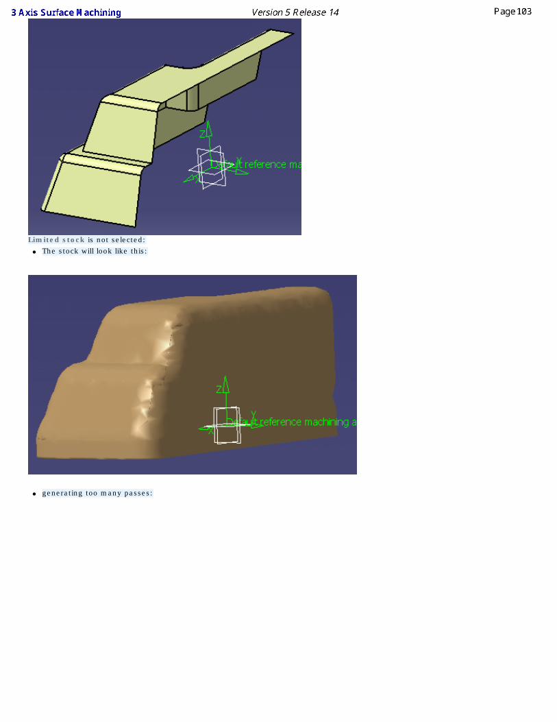
Limited stock is not selected:● The stock will look like this:
● generating too many passes:
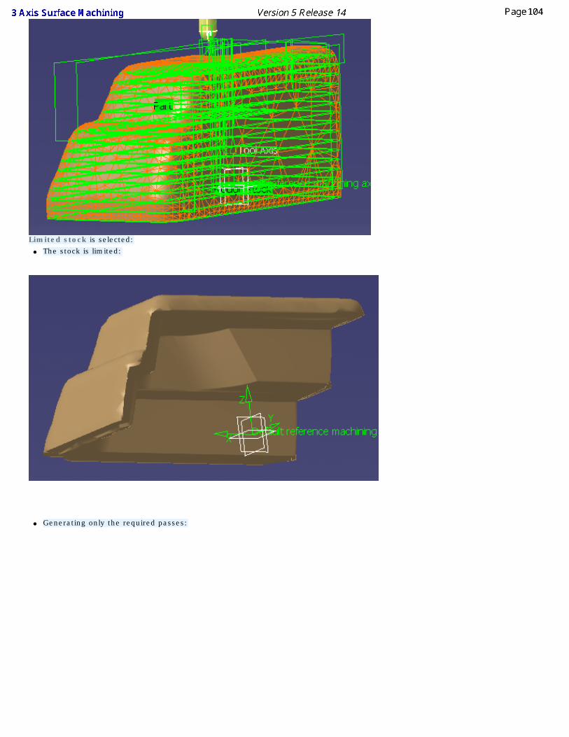
Limited stock is selected:● The stock is limited:
● Generating only the required passes:
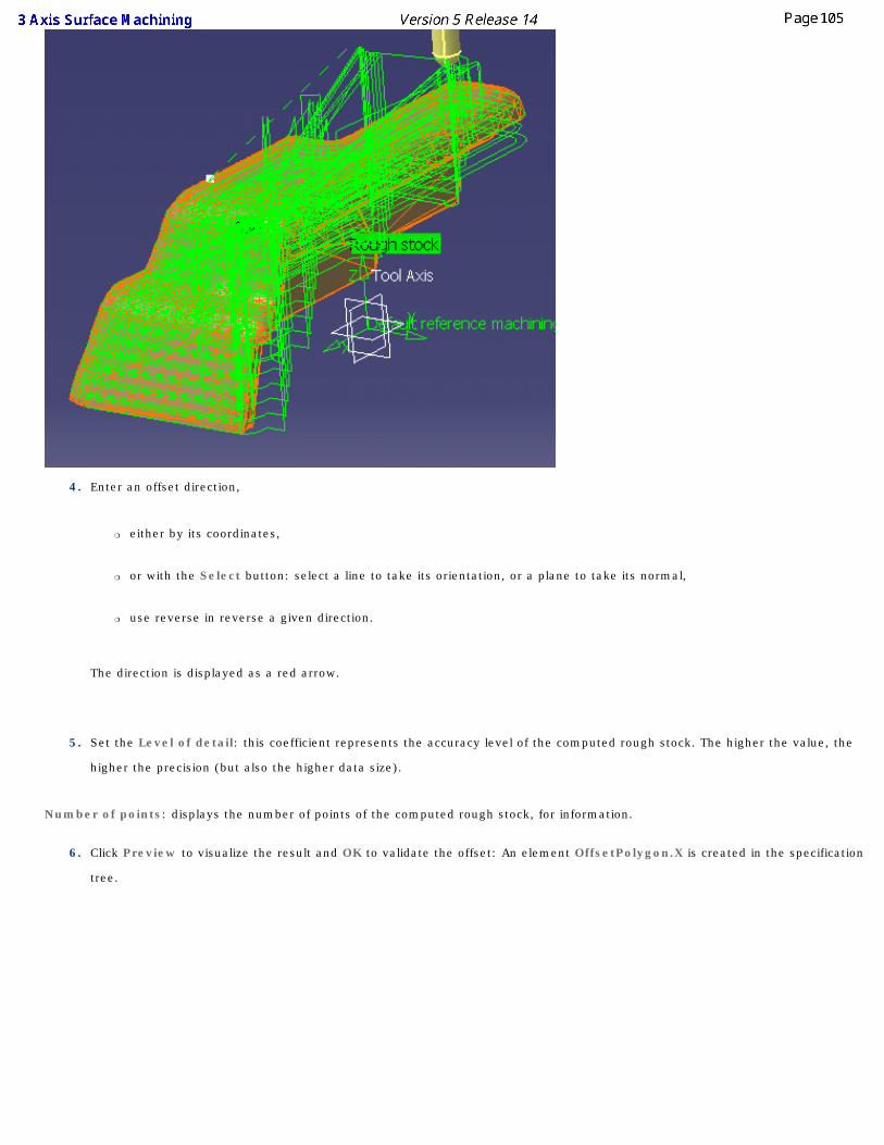
4. Enter an offset direction,
❍ either by its coordinates,
❍ or with the Select button: select a line to take its orientation, or a plane to take its normal,
❍ use reverse in reverse a given direction.
The direction is displayed as a red arrow.
5. Set the Level of detail: this coefficient represents the accuracy level of the computed rough stock. The higher the value, the
higher the precision (but also the higher data size).
Number of points: displays the number of points of the computed rough stock, for information.
6. Click Preview to visualize the result and OK to validate the offset: An element OffsetPolygon.X is created in the specification
tree.
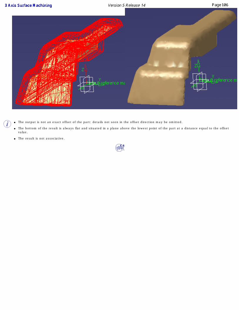
● The output is not an exact offset of the part: details not seen in the offset direction may be omitted.
● The bottom of the result is always flat and situated in a plane above the lowest point of the part at a distance equal to the offset value.
● The result is not associative.
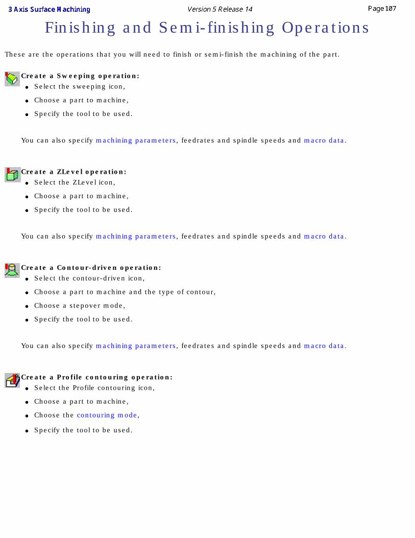
Finishing and Semi-finishing OperationsThese are the operations that you will need to finish or semi-finish the machining of the part.
Create a Sweeping operation: ● Select the sweeping icon,
● Choose a part to machine,
● Specify the tool to be used.
You can also specify machining parameters, feedrates and spindle speeds and macro data.
Create a ZLevel operation:
● Select the ZLevel icon,
● Choose a part to machine,
● Specify the tool to be used.
You can also specify machining parameters, feedrates and spindle speeds and macro data.
Create a Contour-driven operation:
● Select the contour-driven icon,
● Choose a part to machine and the type of contour,
● Choose a stepover mode,
● Specify the tool to be used.
You can also specify machining parameters, feedrates and spindle speeds and macro data.
Create a Profile contouring operation:
● Select the Profile contouring icon,
● Choose a part to machine,
● Choose the contouring mode,
● Specify the tool to be used.
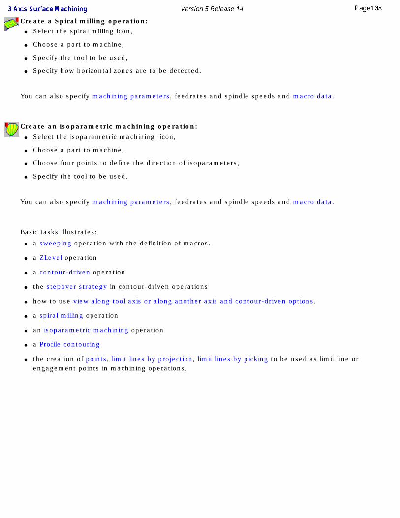
Create a Spiral milling operation: ● Select the spiral milling icon,
● Choose a part to machine,
● Specify the tool to be used,
● Specify how horizontal zones are to be detected.
You can also specify machining parameters, feedrates and spindle speeds and macro data.
Create an isoparametric machining operation:
● Select the isoparametric machining icon,
● Choose a part to machine,
● Choose four points to define the direction of isoparameters,
● Specify the tool to be used.
You can also specify machining parameters, feedrates and spindle speeds and macro data.
Basic tasks illustrates:
● a sweeping operation with the definition of macros.
● a ZLevel operation
● a contour-driven operation
● the stepover strategy in contour-driven operations
● how to use view along tool axis or along another axis and contour-driven options.
● a spiral milling operation
● an isoparametric machining operation
● a Profile contouring
● the creation of points, limit lines by projection, limit lines by picking to be used as limit line or engagement points in machining operations.
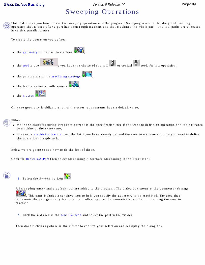
Sweeping OperationsThis task shows you how to insert a sweeping operation into the program. Sweeping is a semi-finishing and finishing operation that is used after a part has been rough machine and that machines the whole part. The tool paths are executed in vertical parallel planes.
To create the operation you define:
● the geometry of the part to machine ,
● the tool to use ; you have the choice of end mill or conical tools for this operation,
● the parameters of the machining strategy ,
● the feedrates and spindle speeds ,
● the macros .
Only the geometry is obligatory, all of the other requirements have a default value.
Either:
● make the Manufacturing Program current in the specification tree if you want to define an operation and the part/area to machine at the same time,
● or select a machining feature from the list if you have already defined the area to machine and now you want to define the operation to apply to it.
Below we are going to see how to do the first of these.
Open file Basic1.CATPart then select Machining > Surface Machining in the Start menu.
1. Select the Sweeping icon .
A Sweeping entity and a default tool are added to the program. The dialog box opens at the geometry tab page
. This page includes a sensitive icon to help you specify the geometry to be machined. The area that represents the part geometry is colored red indicating that the geometry is required for defining the area to machine.
2. Click the red area in the sensitive icon and select the part in the viewer.
Then double click anywhere in the viewer to confirm your selection and redisplay the dialog box.
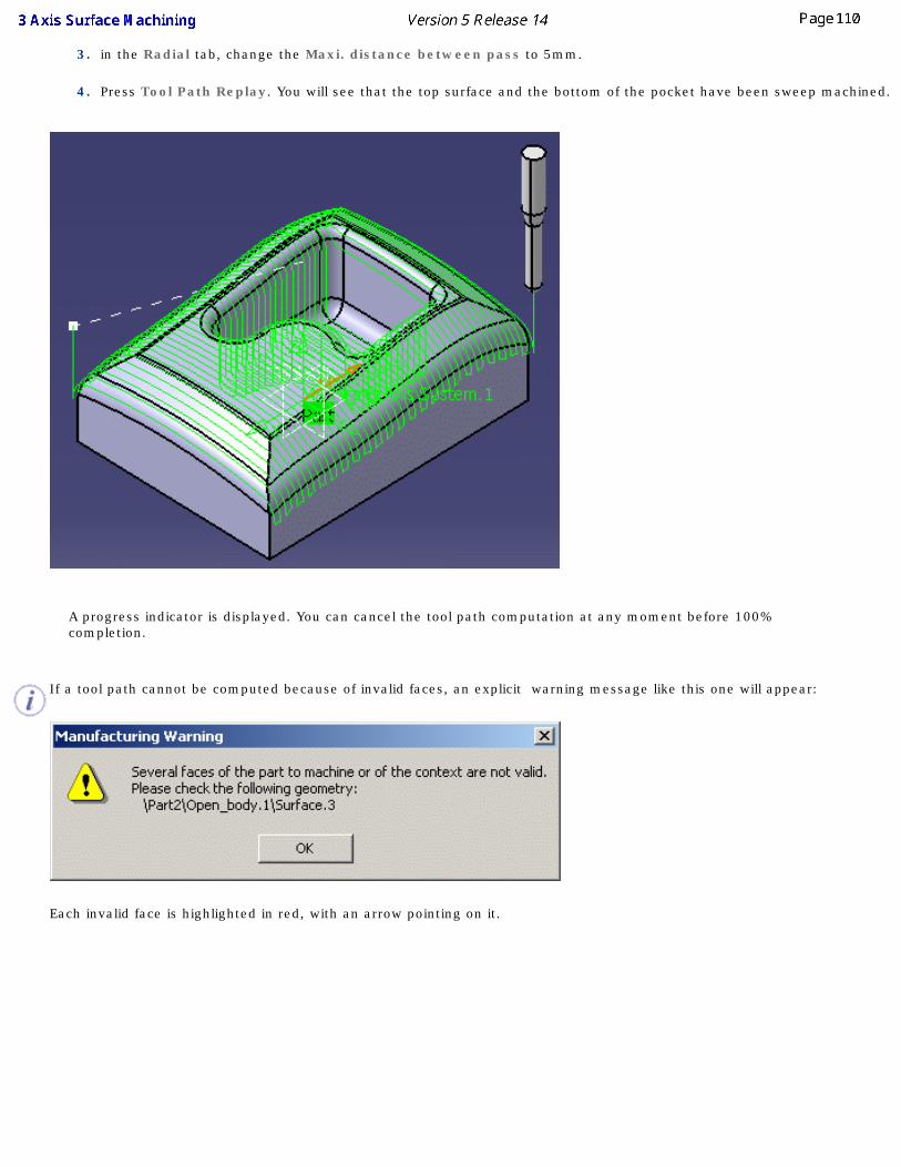
3. in the Radial tab, change the Maxi. distance between pass to 5mm.
4. Press Tool Path Replay. You will see that the top surface and the bottom of the pocket have been sweep machined.
A progress indicator is displayed. You can cancel the tool path computation at any moment before 100% completion.
If a tool path cannot be computed because of invalid faces, an explicit warning message like this one will appear:
Each invalid face is highlighted in red, with an arrow pointing on it.
This visualization is removed when you close the main dialog box or when you select Remove in the contextual menu.
Click OK in the Warning box to revert to the main dialog box.
In the Geometry tab, a message Ignore invalid faces: No is displayed:
You can either:
● close the dialog box. When you reopen it, the Ignore invalid faces: No will not be displayed.
● heal the defective geometry and restart the computation. If it is successful the message Ignore invalid faces: No will disappear.
● ignore the invalid faces. Pick the text Ignore invalid faces: No. It will turn to Ignore invalid faces: Yes and the
computation will continue. The message remains displayed as a warning.
Be very careful when you choose to ignore invalid faces. We recommend that you ignore only faces that will not affect the tool path. Otherwise this may lead to defective tool paths.
Defining macros
The operating mode described hereunder is available for all 3 Axis Surface Machining operations with the exception of the Roughing operations where only the numeric mode is available, and the ZLevel operations where the three modes below are proposed, but with a limited number of motion types to avoid inconsistencies.
5. Go to the macros tab .
You are offered three methods to add the macros:
● the catalog method. are used respectively to save a macro in a catalog and read a macro from a catalog. For
more information on how to save or load an existing macro, please refer to Build and use a macros catalog.
● the graphic method, using macros proposed by the application,
● the numeric method, by defining yourself the macros.
In the Macro Management frame, you will find the list of the type of macro that can be defined for the current machining
operation. For each type, you will find the Status of the geometry, the Name of the macro and the machining Mode
affected to this macro.
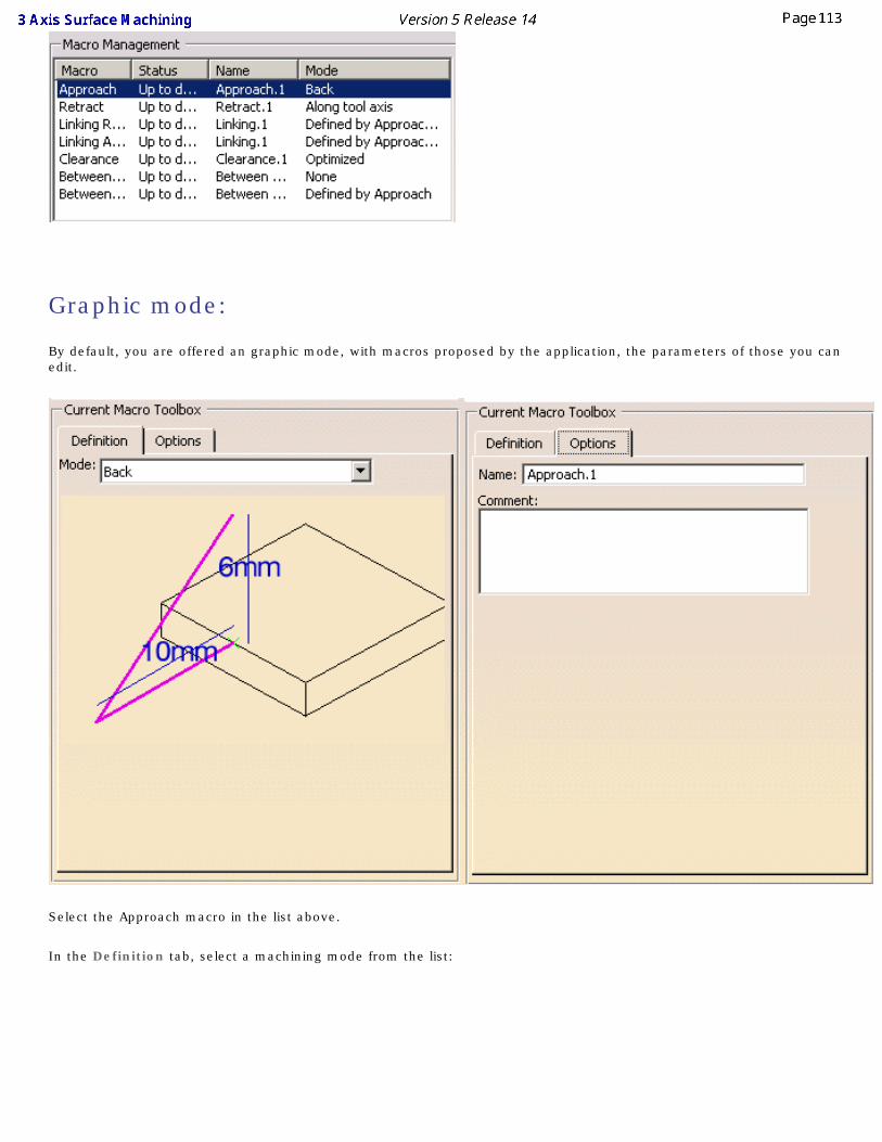
Graphic mode:
By default, you are offered an graphic mode, with macros proposed by the application, the parameters of those you can edit.
Select the Approach macro in the list above.
In the Definition tab, select a machining mode from the list:
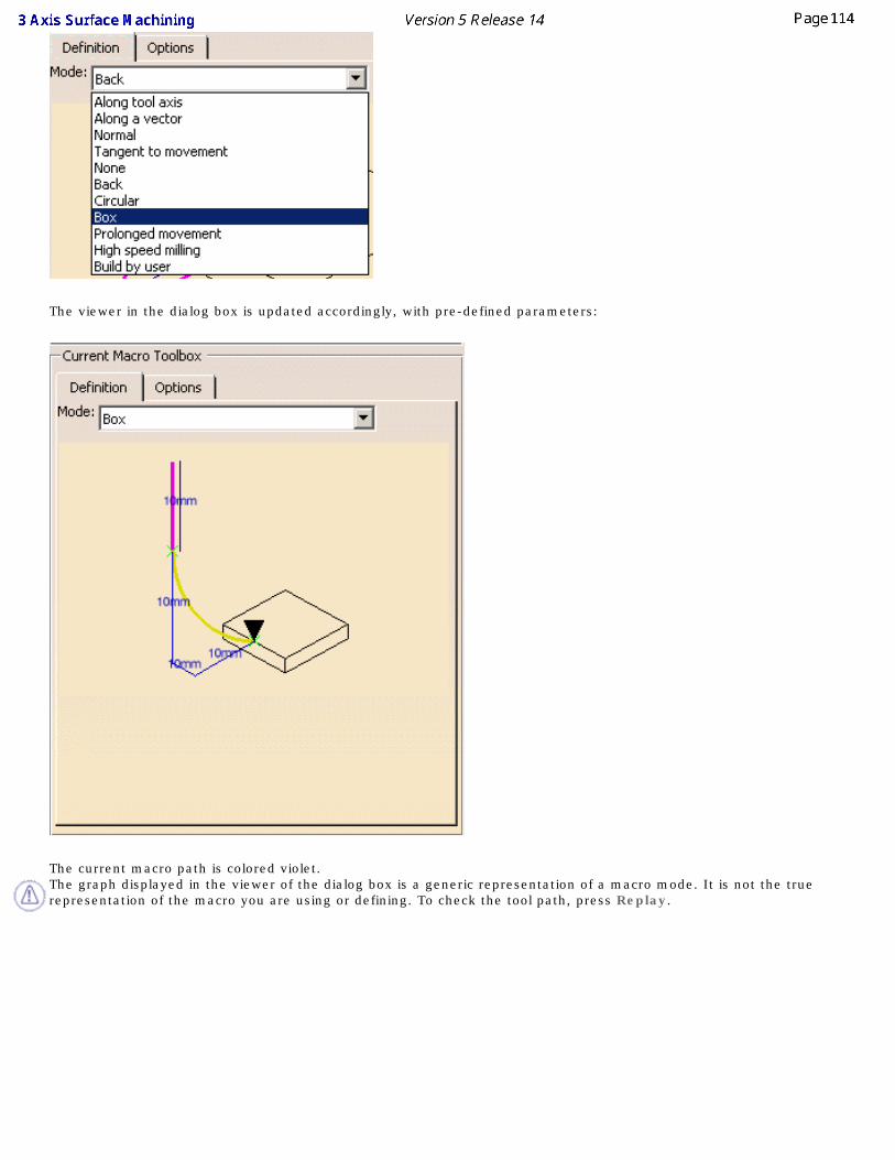
The viewer in the dialog box is updated accordingly, with pre-defined parameters:
The current macro path is colored violet. The graph displayed in the viewer of the dialog box is a generic representation of a macro mode. It is not the true representation of the macro you are using or defining. To check the tool path, press Replay.
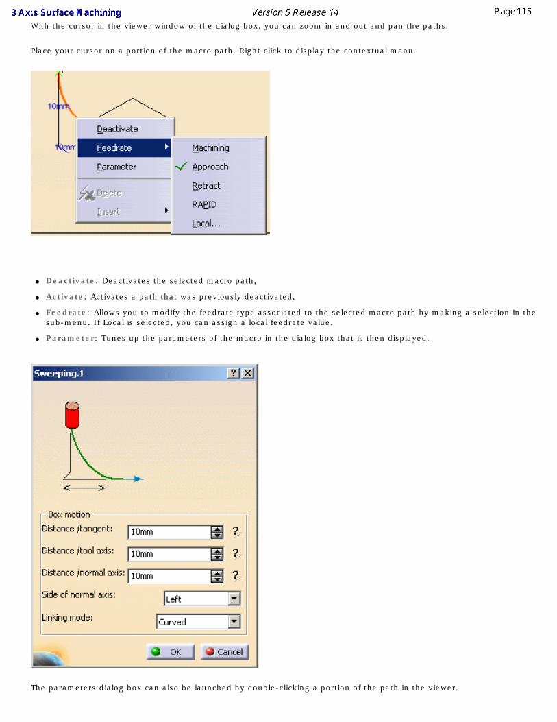
With the cursor in the viewer window of the dialog box, you can zoom in and out and pan the paths.
Place your cursor on a portion of the macro path. Right click to display the contextual menu.
● Deactivate: Deactivates the selected macro path,
● Activate: Activates a path that was previously deactivated,
● Feedrate: Allows you to modify the feedrate type associated to the selected macro path by making a selection in the sub-menu. If Local is selected, you can assign a local feedrate value.
● Parameter: Tunes up the parameters of the macro in the dialog box that is then displayed.
The parameters dialog box can also be launched by double-clicking a portion of the path in the viewer.
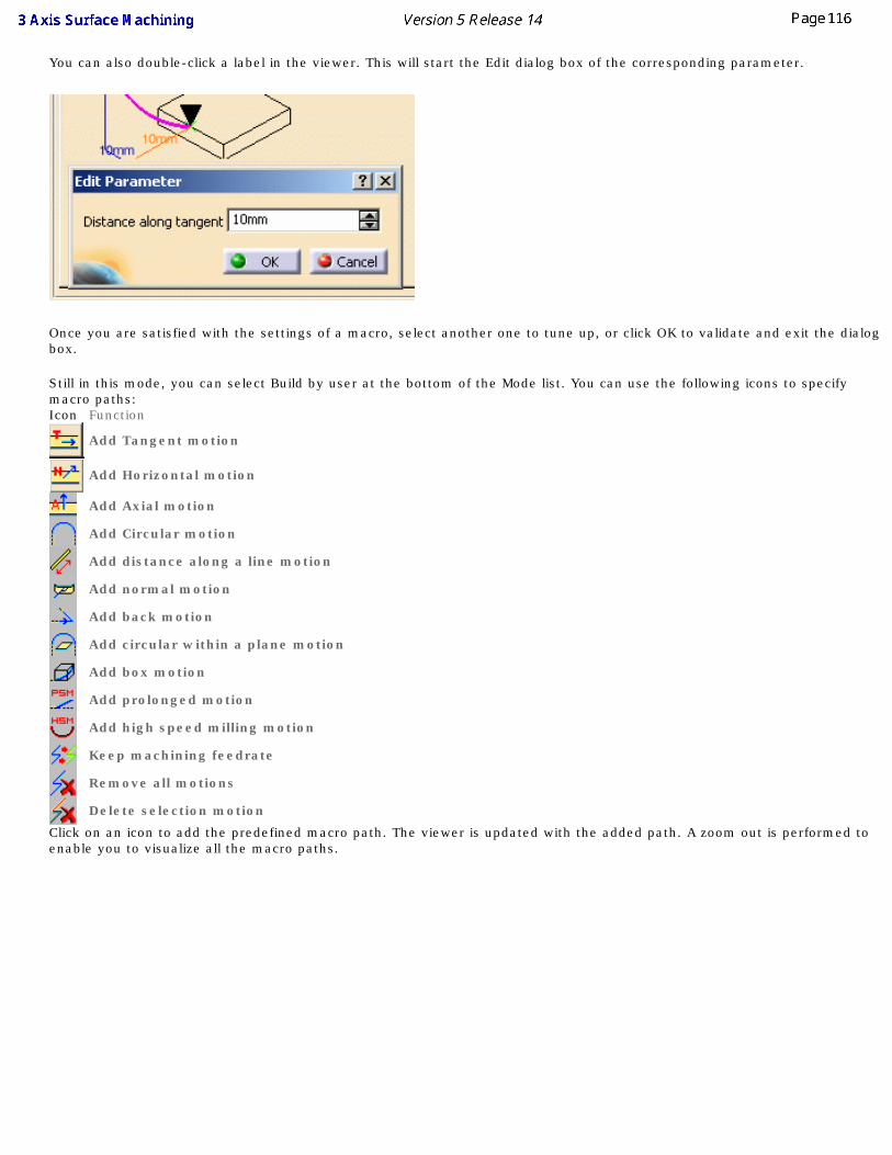
You can also double-click a label in the viewer. This will start the Edit dialog box of the corresponding parameter.
Once you are satisfied with the settings of a macro, select another one to tune up, or click OK to validate and exit the dialog box.
Still in this mode, you can select Build by user at the bottom of the Mode list. You can use the following icons to specify macro paths:Icon Function
Add Tangent motion
Add Horizontal motion
Add Axial motion
Add Circular motion
Add distance along a line motion
Add normal motion
Add back motion
Add circular within a plane motion
Add box motion
Add prolonged motion
Add high speed milling motion
Keep machining feedrate
Remove all motions
Delete selection motion
Click on an icon to add the predefined macro path. The viewer is updated with the added path. A zoom out is performed to enable you to visualize all the macro paths.
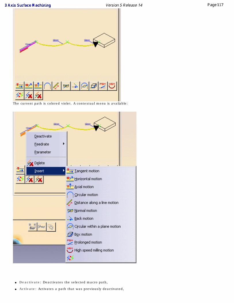
The current path is colored violet. A contextual menu is available:
● Deactivate: Deactivates the selected macro path,
● Activate: Activates a path that was previously deactivated,
● Feedrate: Allows you to modify the feedrate type associated to the selected macro path by making a selection in the sub-menu. If Local is selected, you can assign a local feedrate value.
● Parameter: Tunes up the parameters of the macro in the dialog box that is then displayed.
The parameters dialog box can also be launched by double-clicking a portion of the path in the viewer.
● Delete: Deletes the current macro path
● Insert: Inserts another macro path.
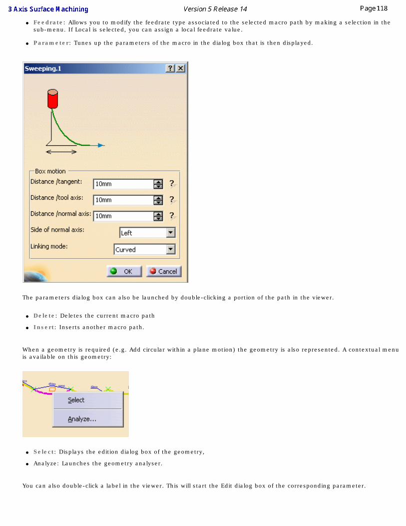
When a geometry is required (e.g. Add circular within a plane motion) the geometry is also represented. A contextual menu is available on this geometry:
● Select: Displays the edition dialog box of the geometry,
● Analyze: Launches the geometry analyser.
You can also double-click a label in the viewer. This will start the Edit dialog box of the corresponding parameter.
The graph displayed in the viewer of the dialog box is a generic representation of a macro mode. It is not the true representation of the macro you are using or defining. To check the result of you settings, press Replay.
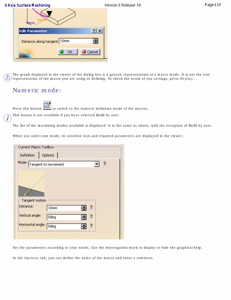
Numeric mode:
Press this button to switch to the numeric definition mode of the macros.
This button is not available if you have selected Build by user.
The list of the machining modes available is displayed. It is the same as above, with the exception of Build by user.
When you select one mode, its sensitive icon and required parameters are displayed in the viewer :
Set the parameters according to your needs. Use the interrogation mark to display or hide the graphical help.
In the Options tab, you can define the name of the macro and enter a comment.

More information is available in the Macro Reference chapter.
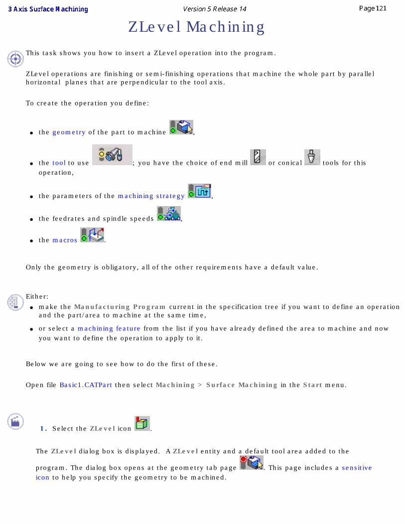
ZLevel Machining This task shows you how to insert a ZLevel operation into the program.
ZLevel operations are finishing or semi-finishing operations that machine the whole part by parallel horizontal planes that are perpendicular to the tool axis.
To create the operation you define:
● the geometry of the part to machine ,
● the tool to use ; you have the choice of end mill or conical tools for this operation,
● the parameters of the machining strategy ,
● the feedrates and spindle speeds ,
● the macros .
Only the geometry is obligatory, all of the other requirements have a default value.
Either:
● make the Manufacturing Program current in the specification tree if you want to define an operation and the part/area to machine at the same time,
● or select a machining feature from the list if you have already defined the area to machine and now you want to define the operation to apply to it.
Below we are going to see how to do the first of these.
Open file Basic1.CATPart then select Machining > Surface Machining in the Start menu.
1. Select the ZLevel icon .
The ZLevel dialog box is displayed. A ZLevel entity and a default tool area added to the
program. The dialog box opens at the geometry tab page . This page includes a sensitive icon to help you specify the geometry to be machined.
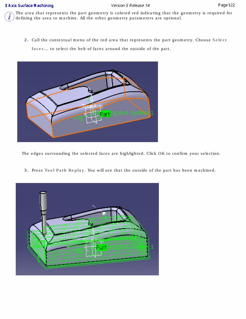
The area that represents the part geometry is colored red indicating that the geometry is required for defining the area to machine. All the other geometry parameters are optional.
2. Call the contextual menu of the red area that represents the part geometry. Choose Select
faces... to select the belt of faces around the outside of the part.
The edges surrounding the selected faces are highlighted. Click OK to confirm your selection.
3. Press Tool Path Replay. You will see that the outside of the part has been machined.
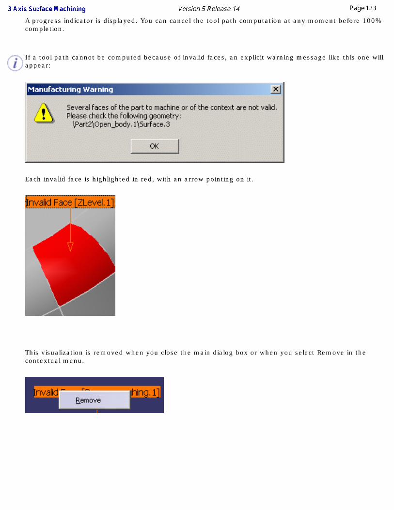
A progress indicator is displayed. You can cancel the tool path computation at any moment before 100% completion.
If a tool path cannot be computed because of invalid faces, an explicit warning message like this one will appear:
Each invalid face is highlighted in red, with an arrow pointing on it.
This visualization is removed when you close the main dialog box or when you select Remove in the contextual menu.
Click OK in the Warning box to revert to the main dialog box.
In the Geometry tab, a message Ignore invalid faces: No is displayed:
You can either:
● close the dialog box. When you reopen it, the Ignore invalid faces: No will not be displayed.
● heal the defective geometry and restart the computation. If it is successful the message Ignore invalid faces: No will disappear.
● ignore the invalid faces. Pick the text Ignore invalid faces: No. It will turn to Ignore invalid faces: Yes and the computation will continue. The message remains displayed as a warning.
Be very careful when you choose to ignore invalid faces. We recommend that you ignore only faces that will not affect the tool path. Otherwise this may lead to defective tool paths.
Contour-driven Machining
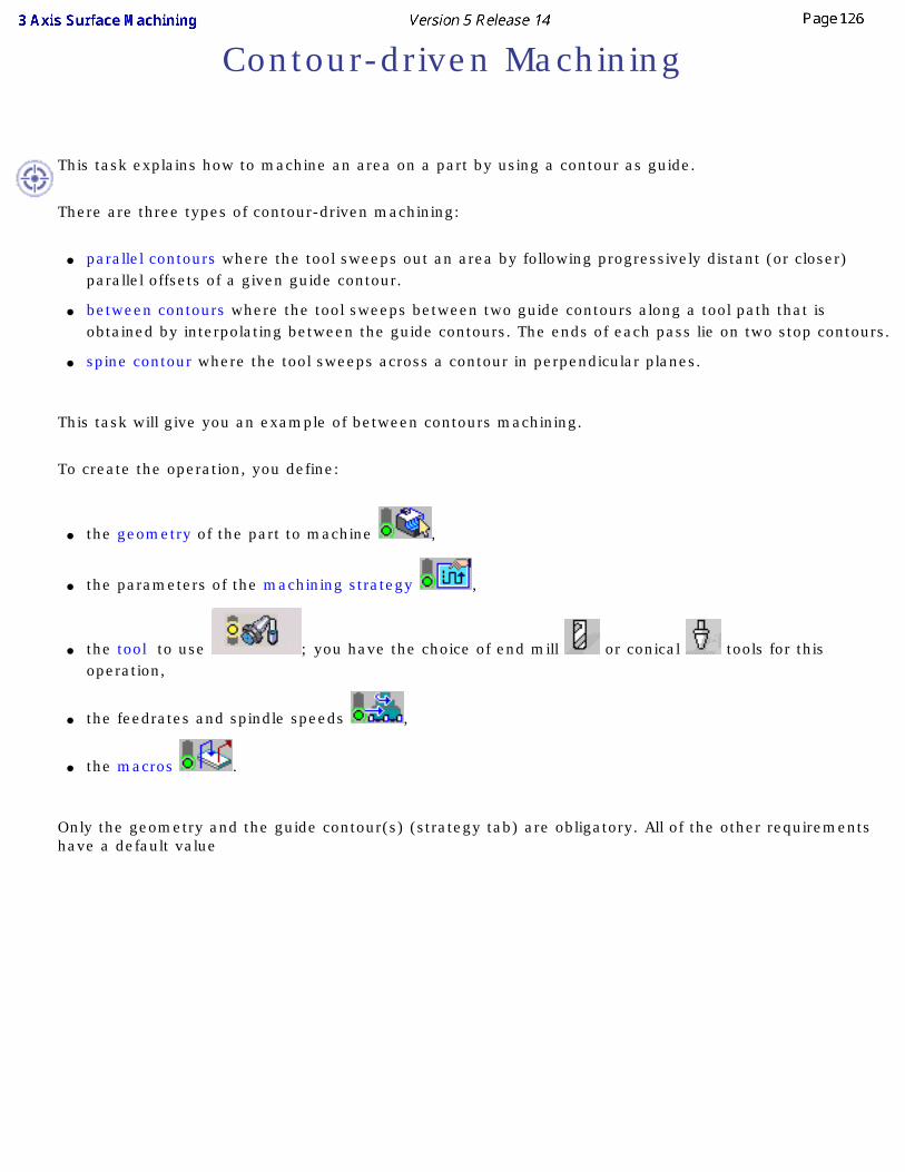
This task explains how to machine an area on a part by using a contour as guide.
There are three types of contour-driven machining:
● parallel contours where the tool sweeps out an area by following progressively distant (or closer) parallel offsets of a given guide contour.
● between contours where the tool sweeps between two guide contours along a tool path that is obtained by interpolating between the guide contours. The ends of each pass lie on two stop contours.
● spine contour where the tool sweeps across a contour in perpendicular planes.
This task will give you an example of between contours machining.
To create the operation, you define:
● the geometry of the part to machine ,
● the parameters of the machining strategy ,
● the tool to use ; you have the choice of end mill or conical tools for this operation,
● the feedrates and spindle speeds ,
● the macros .
Only the geometry and the guide contour(s) (strategy tab) are obligatory. All of the other requirements have a default value
Either: ● make the Manufacturing Program current in the specification tree if you want to define an operation
and the part/area to machine at the same time,
● or select a machining feature from the list if you have already defined the area to machine and now you want to define the operation to apply to it.
Below we are going to see how to do the first of these with a between contours operation on a small area of a part.
Open file Basic2.CATPart, then select Machining > Surface Machining in the Start menu.
1. Select the Contour-driven icon .
The Contour-driven dialog box is displayed. The dialog box opens at the geometry tab page
.
2. Click the red area in the sensitive icon and select the part in the viewer.
Double click anywhere in the viewer to confirm your selection and redisplay the dialog box.
3. Go to the Strategy tab. Check the Between contours option.
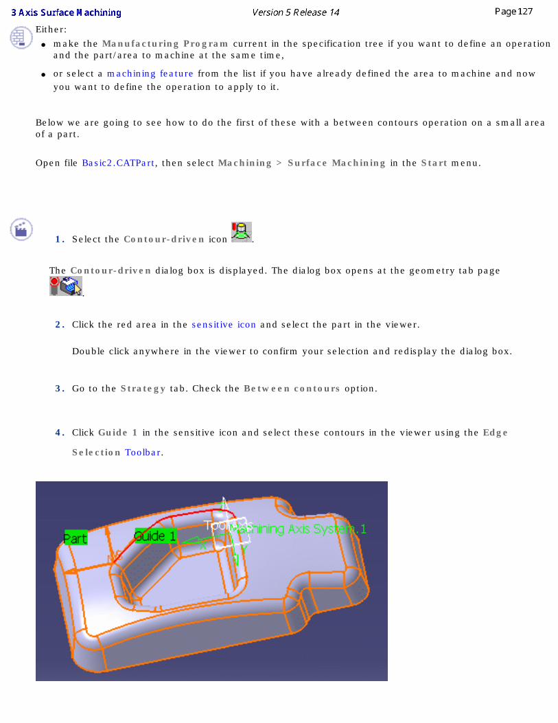
4. Click Guide 1 in the sensitive icon and select these contours in the viewer using the Edge
Selection Toolbar.
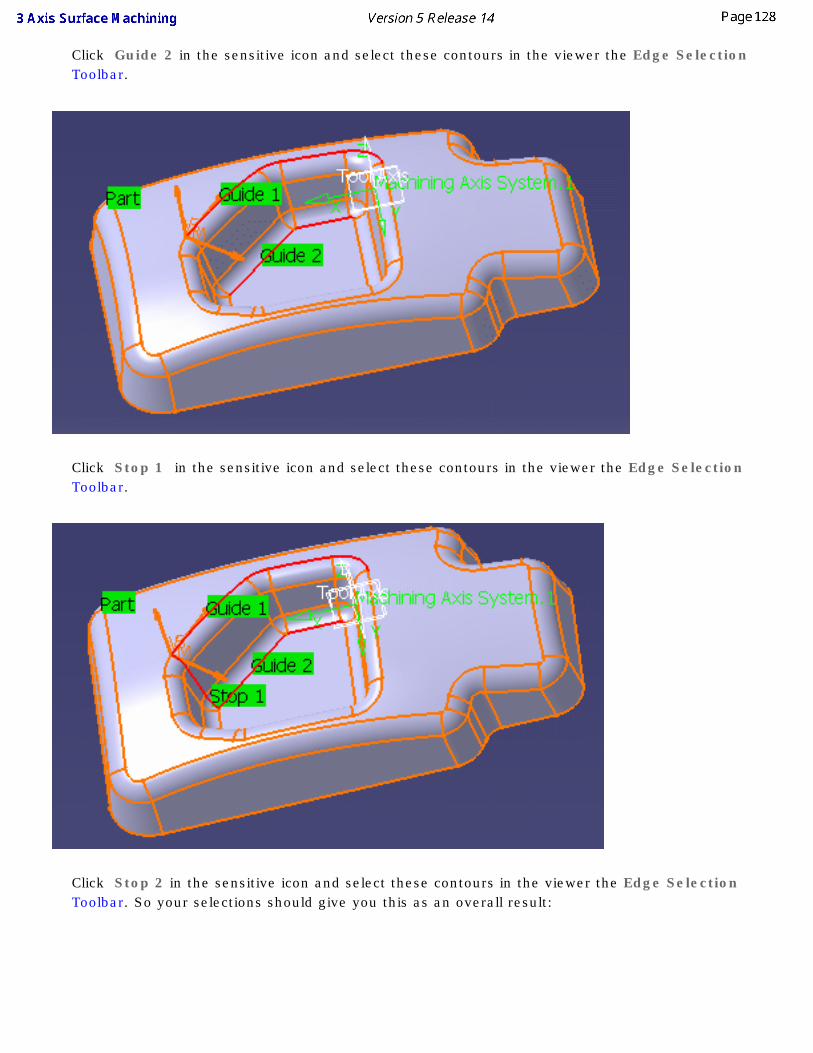
Click Guide 2 in the sensitive icon and select these contours in the viewer the Edge Selection Toolbar.
Click Stop 1 in the sensitive icon and select these contours in the viewer the Edge Selection Toolbar.
Click Stop 2 in the sensitive icon and select these contours in the viewer the Edge Selection Toolbar. So your selections should give you this as an overall result:
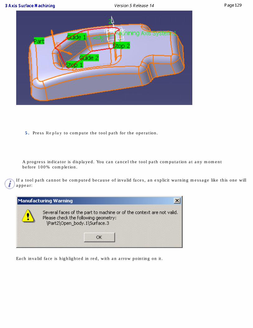
5. Press Replay to compute the tool path for the operation.
A progress indicator is displayed. You can cancel the tool path computation at any moment before 100% completion.
If a tool path cannot be computed because of invalid faces, an explicit warning message like this one will appear:
Each invalid face is highlighted in red, with an arrow pointing on it.

This visualization is removed when you close the main dialog box or when you select Remove in the contextual menu.
Click OK in the Warning box to revert to the main dialog box.
In the Geometry tab, a message Ignore invalid faces: No is displayed:

You can either:
● close the dialog box. When you reopen it, the Ignore invalid faces: No will not be displayed.
● heal the defective geometry and restart the computation. If it is successful the message Ignore invalid faces: No will disappear.
● ignore the invalid faces. Pick the text Ignore invalid faces: No. It will turn to Ignore invalid faces: Yes and the computation will continue. The message remains displayed as a warning.
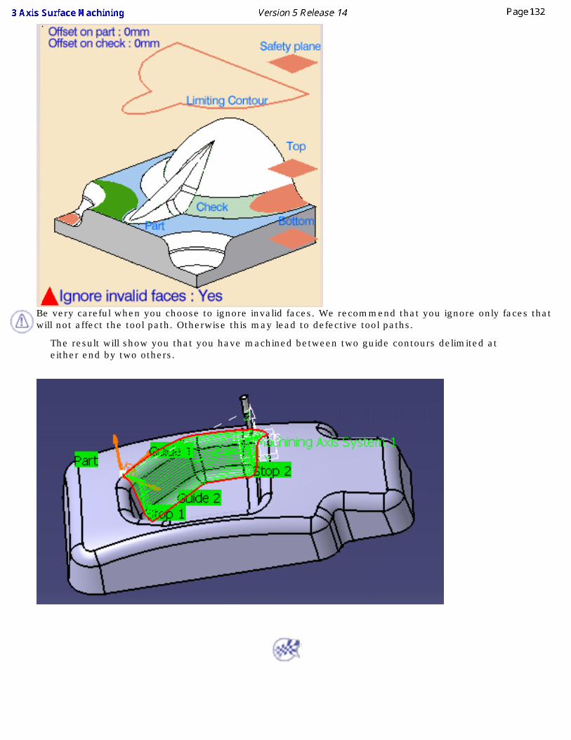
Be very careful when you choose to ignore invalid faces. We recommend that you ignore only faces that will not affect the tool path. Otherwise this may lead to defective tool paths.
The result will show you that you have machined between two guide contours delimited at either end by two others.
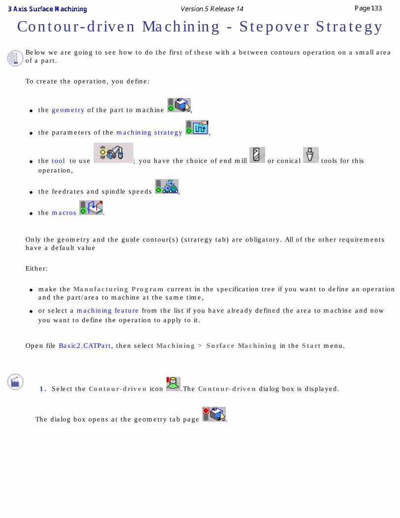
Contour-driven Machining - Stepover StrategyBelow we are going to see how to do the first of these with a between contours operation on a small area of a part.
To create the operation, you define:
● the geometry of the part to machine ,
● the parameters of the machining strategy ,
● the tool to use ; you have the choice of end mill or conical tools for this operation,
● the feedrates and spindle speeds ,
● the macros .
Only the geometry and the guide contour(s) (strategy tab) are obligatory. All of the other requirements have a default value
Either:
● make the Manufacturing Program current in the specification tree if you want to define an operation and the part/area to machine at the same time,
● or select a machining feature from the list if you have already defined the area to machine and now you want to define the operation to apply to it.
Open file Basic2.CATPart, then select Machining > Surface Machining in the Start menu.
1. Select the Contour-driven icon .The Contour-driven dialog box is displayed.
The dialog box opens at the geometry tab page .
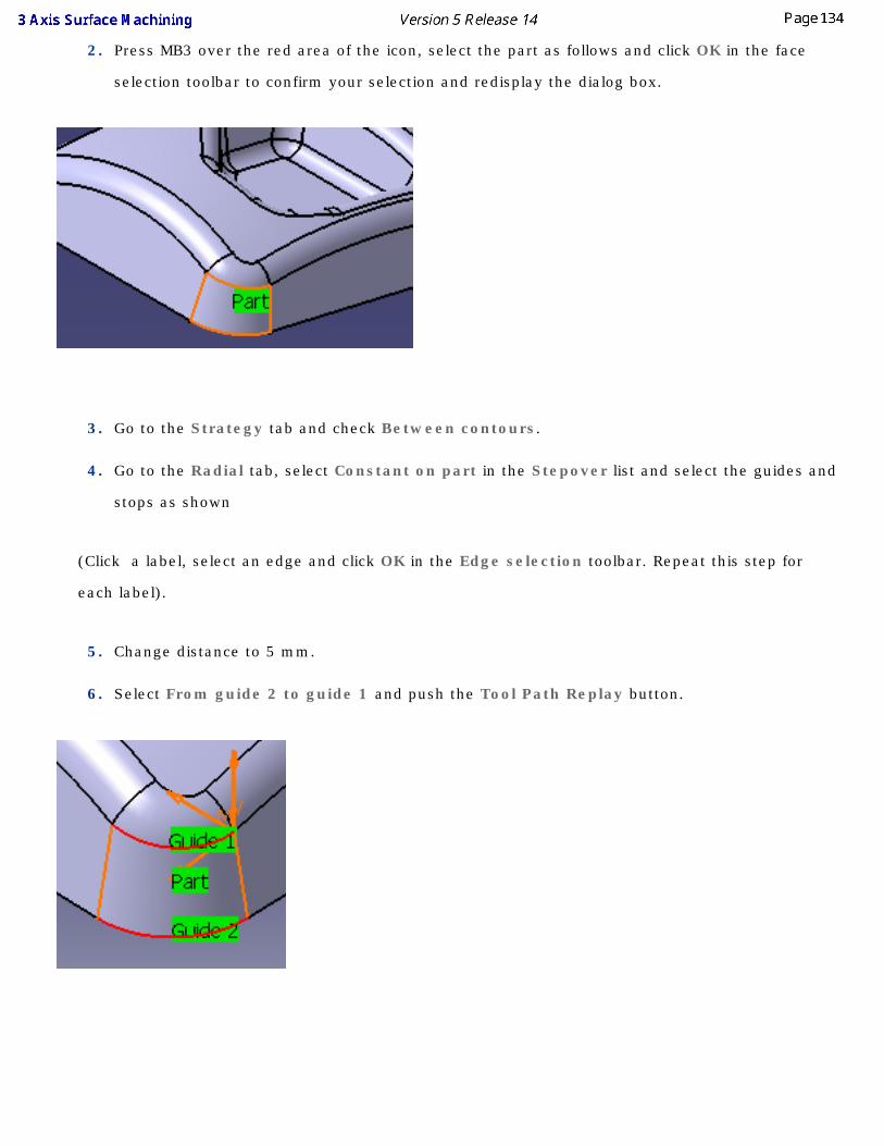
2. Press MB3 over the red area of the icon, select the part as follows and click OK in the face
selection toolbar to confirm your selection and redisplay the dialog box.
3. Go to the Strategy tab and check Between contours.
4. Go to the Radial tab, select Constant on part in the Stepover list and select the guides and
stops as shown
(Click a label, select an edge and click OK in the Edge selection toolbar. Repeat this step for
each label).
5. Change distance to 5 mm.
6. Select From guide 2 to guide 1 and push the Tool Path Replay button.

The result is of an equal distance on the part surface from guide 2 to guide 1
Note the bottom of the machined area and how the paths remain perfectly parallel to each other but because of the shape of the surface they finish gradually on guide 1.
7. With the same parameters, switch to Maximum on part and push the Tool Path Replay button.
There is a variation in the distance between the paths on the surface but the paths respect both
guide 1 and guide 2. There is no gradual finish on Guide 1 as there was with Constant on part.
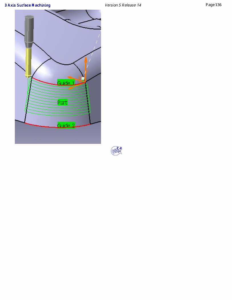
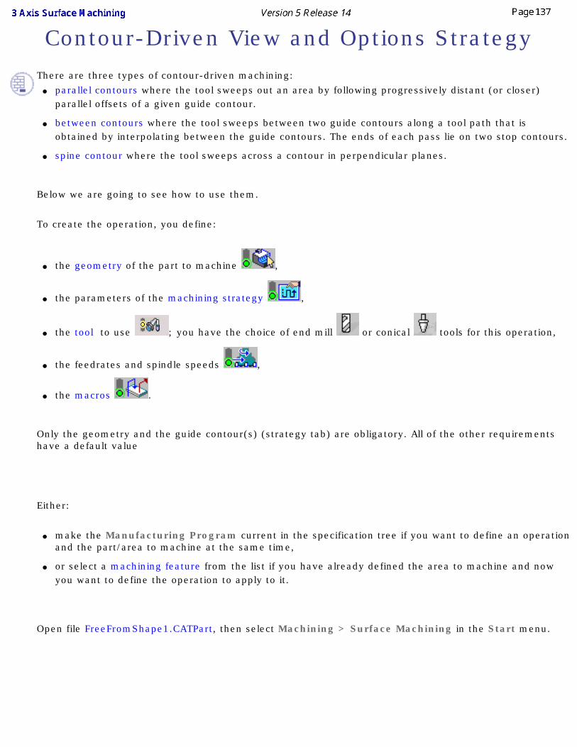
Contour-Driven View and Options StrategyThere are three types of contour-driven machining:
● parallel contours where the tool sweeps out an area by following progressively distant (or closer) parallel offsets of a given guide contour.
● between contours where the tool sweeps between two guide contours along a tool path that is obtained by interpolating between the guide contours. The ends of each pass lie on two stop contours.
● spine contour where the tool sweeps across a contour in perpendicular planes.
Below we are going to see how to use them.
To create the operation, you define:
● the geometry of the part to machine ,
● the parameters of the machining strategy ,
● the tool to use ; you have the choice of end mill or conical tools for this operation,
● the feedrates and spindle speeds ,
● the macros .
Only the geometry and the guide contour(s) (strategy tab) are obligatory. All of the other requirements have a default value
Either:
● make the Manufacturing Program current in the specification tree if you want to define an operation and the part/area to machine at the same time,
● or select a machining feature from the list if you have already defined the area to machine and now you want to define the operation to apply to it.
Open file FreeFromShape1.CATPart, then select Machining > Surface Machining in the Start menu.
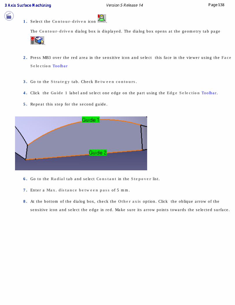
1. Select the Contour-driven icon .
The Contour-driven dialog box is displayed. The dialog box opens at the geometry tab page
.
2. Press MB3 over the red area in the sensitive icon and select this face in the viewer using the Face
Selection Toolbar
3. Go to the Strategy tab. Check Between contours.
4. Click the Guide 1 label and select one edge on the part using the Edge Selection Toolbar.
5. Repeat this step for the second guide.
6. Go to the Radial tab and select Constant in the Stepover list.
7. Enter a Max. distance between pass of 5 mm.
8. At the bottom of the dialog box, check the Other axis option. Click the oblique arrow of the
sensitive icon and select the edge in red. Make sure its arrow points towards the selected surface.
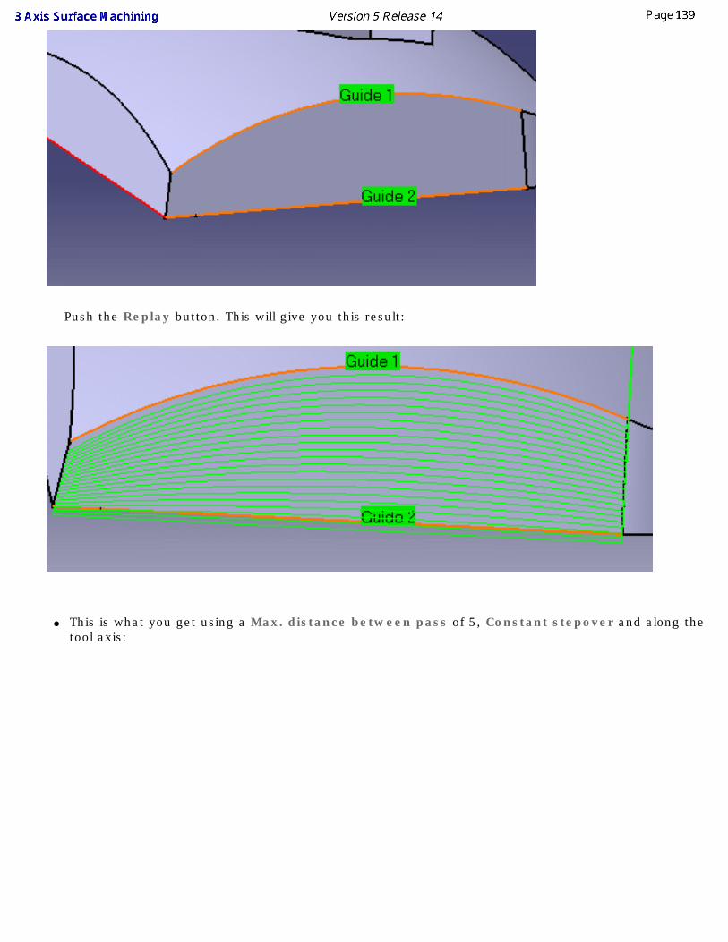
Push the Replay button. This will give you this result:
● This is what you get using a Max. distance between pass of 5, Constant stepover and along the tool axis:
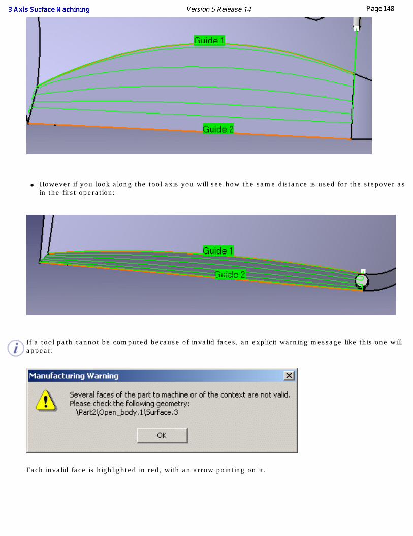
● However if you look along the tool axis you will see how the same distance is used for the stepover as in the first operation:
If a tool path cannot be computed because of invalid faces, an explicit warning message like this one will appear:
Each invalid face is highlighted in red, with an arrow pointing on it.
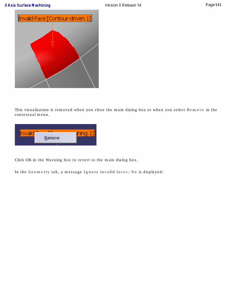
This visualization is removed when you close the main dialog box or when you select Remove in the contextual menu.
Click OK in the Warning box to revert to the main dialog box.
In the Geometry tab, a message Ignore invalid faces: No is displayed:
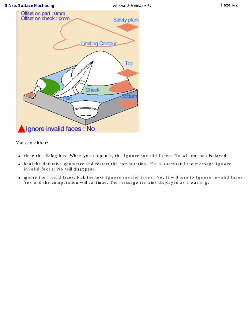
You can either:
● close the dialog box. When you reopen it, the Ignore invalid faces: No will not be displayed.
● heal the defective geometry and restart the computation. If it is successful the message Ignore invalid faces: No will disappear.
● ignore the invalid faces. Pick the text Ignore invalid faces: No. It will turn to Ignore invalid faces: Yes and the computation will continue. The message remains displayed as a warning.
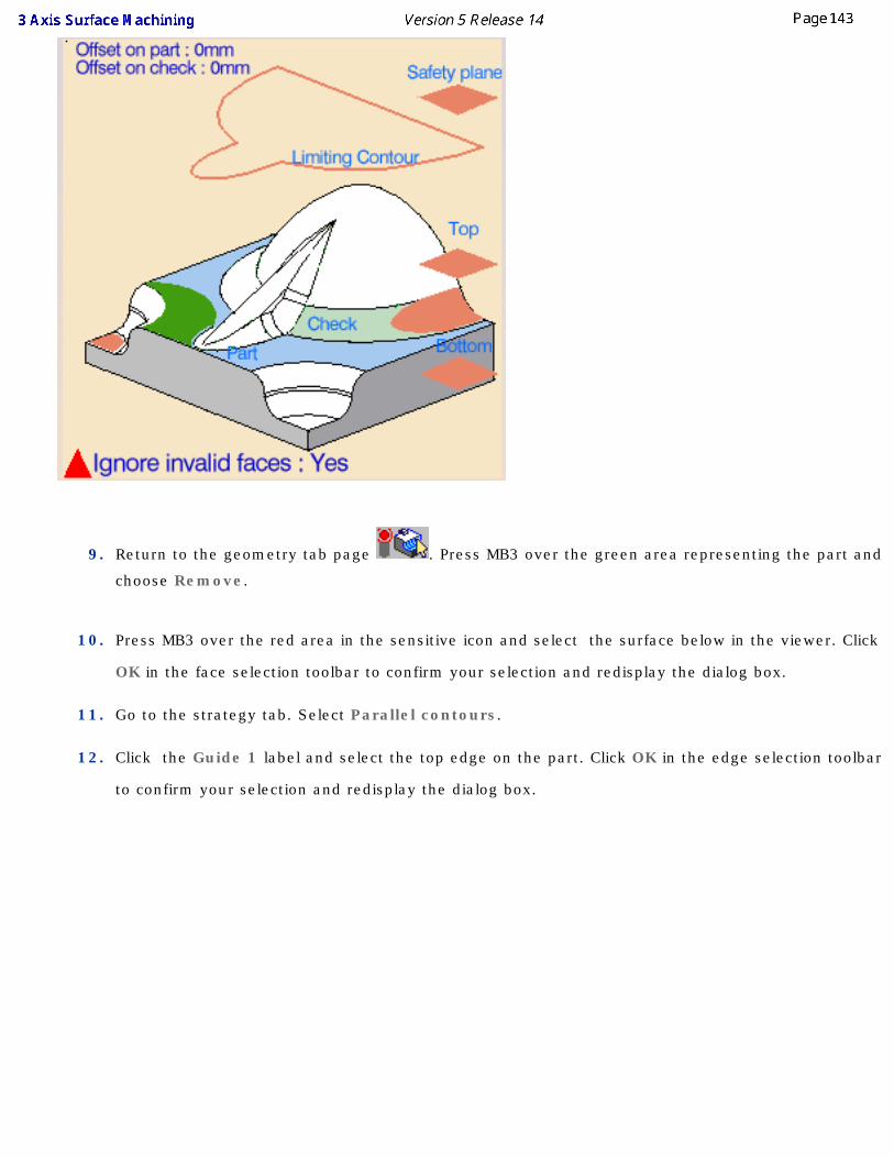
9. Return to the geometry tab page . Press MB3 over the green area representing the part and
choose Remove.
10. Press MB3 over the red area in the sensitive icon and select the surface below in the viewer. Click
OK in the face selection toolbar to confirm your selection and redisplay the dialog box.
11. Go to the strategy tab. Select Parallel contours.
12. Click the Guide 1 label and select the top edge on the part. Click OK in the edge selection toolbar
to confirm your selection and redisplay the dialog box.
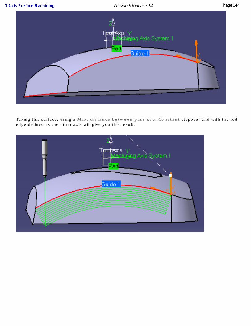
Taking this surface, using a Max. distance between pass of 5, Constant stepover and with the red edge defined as the other axis will give you this result:
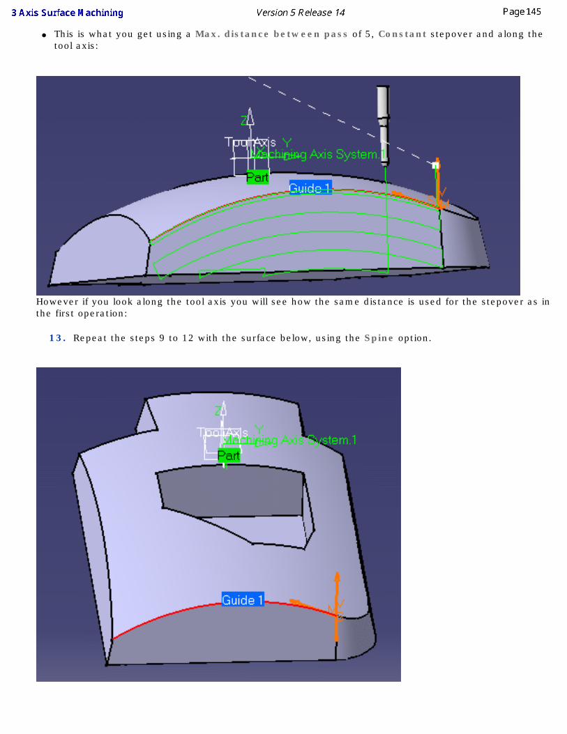
● This is what you get using a Max. distance between pass of 5, Constant stepover and along the tool axis:
However if you look along the tool axis you will see how the same distance is used for the stepover as in the first operation:
13. Repeat the steps 9 to 12 with the surface below, using the Spine option.
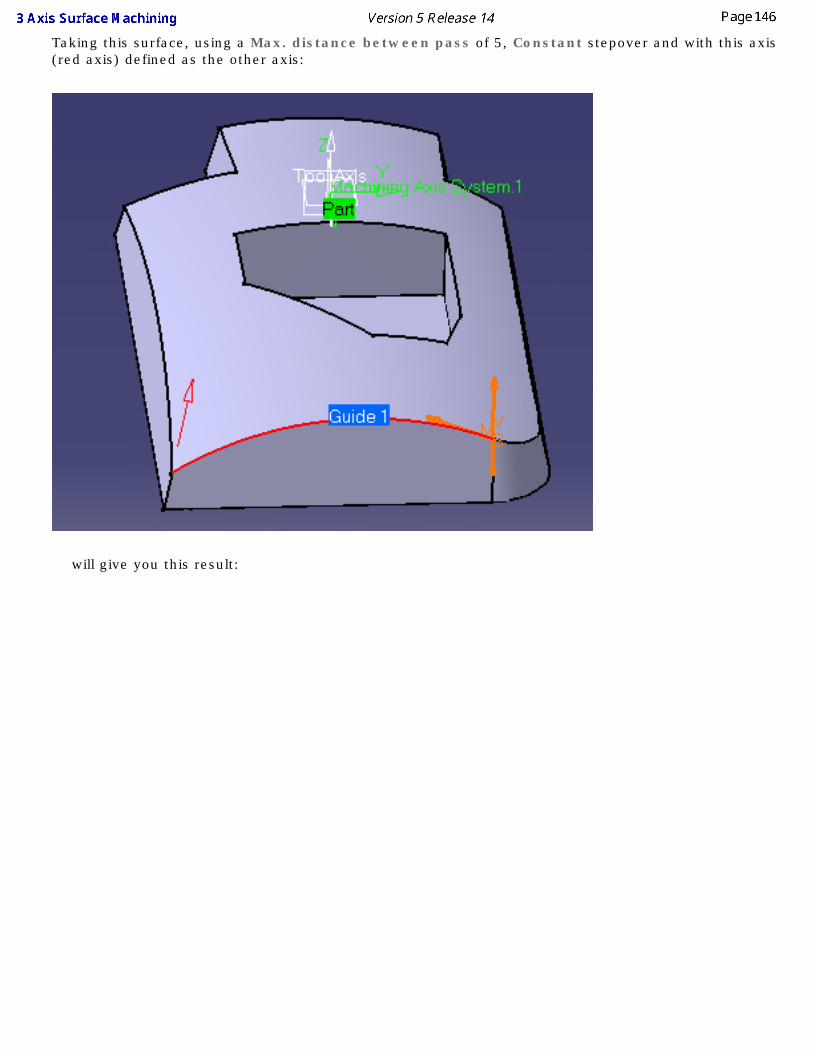
Taking this surface, using a Max. distance between pass of 5, Constant stepover and with this axis (red axis) defined as the other axis:
will give you this result:
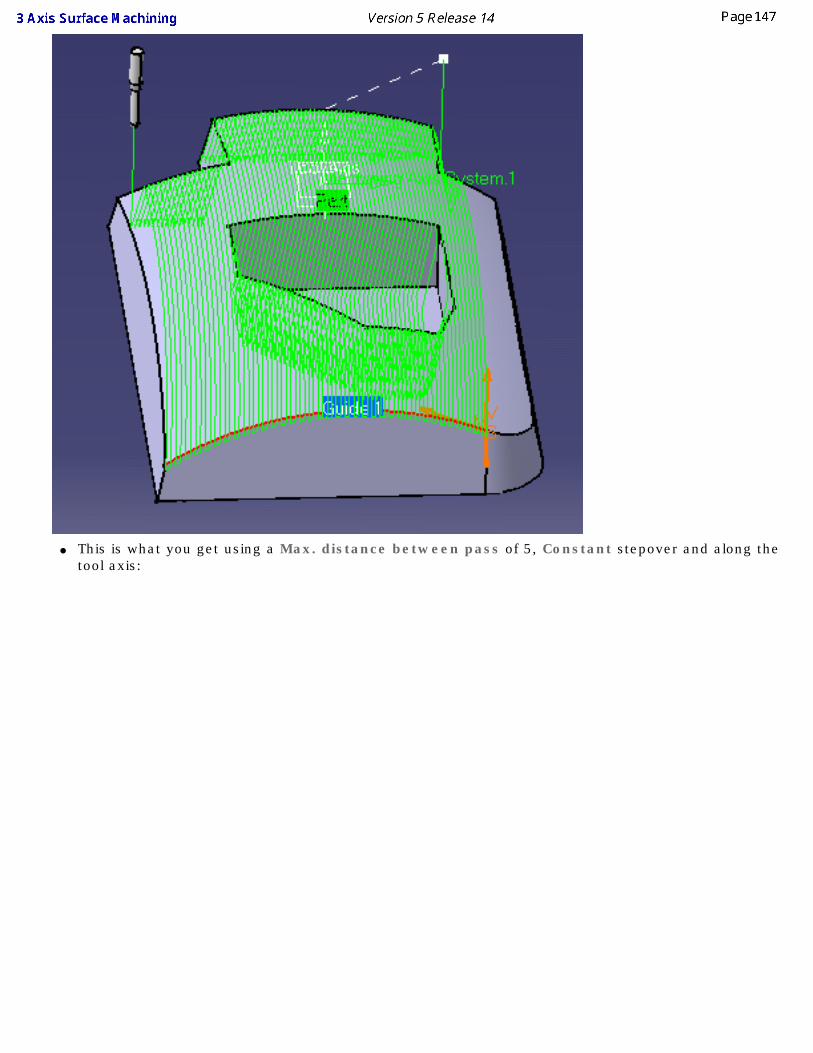
● This is what you get using a Max. distance between pass of 5, Constant stepover and along the tool axis:
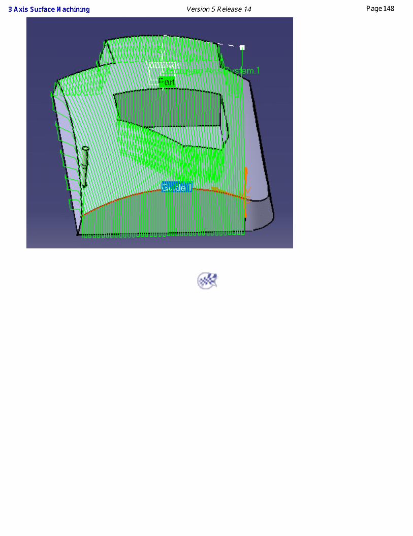
Isoparametric MachiningThis task shows you how to insert a isoparametric machining operation into the program. Isoparametric machining is an operation which allows you to select strips of faces and machine along their isoparametrics.
To create the operation you define:
● the geometry of the part to machine ,
● the parameters of the machining strategy ,
● the tool to use ;end mill, face mill , conical mill and T-slotter tool can be used for this operation,
● the feedrates and spindle speeds ,
● the macros .
Only the geometry is obligatory, all of the other requirements have a default value.
Either:
● make the Manufacturing Program current in the specification tree if you want to define an operation and the part/area to machine at the same time,
● or select a machining feature from the list if you have already defined the area to machine and now you want to define the operation to apply to it.
Below we are going to see how to do the first of these.
Open file Basic2.CATPart then select Machining > Surface Machining in the Start menu.
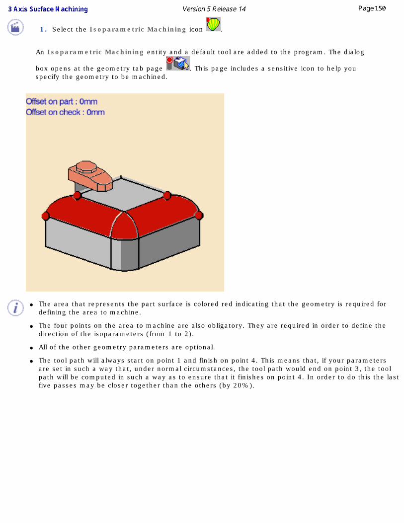
1. Select the Isoparametric Machining icon .
An Isoparametric Machining entity and a default tool are added to the program. The dialog
box opens at the geometry tab page . This page includes a sensitive icon to help you specify the geometry to be machined.
● The area that represents the part surface is colored red indicating that the geometry is required for defining the area to machine.
● The four points on the area to machine are also obligatory. They are required in order to define the direction of the isoparameters (from 1 to 2).
● All of the other geometry parameters are optional.
● The tool path will always start on point 1 and finish on point 4. This means that, if your parameters are set in such a way that, under normal circumstances, the tool path would end on point 3, the tool path will be computed in such a way as to ensure that it finishes on point 4. In order to do this the last five passes may be closer together than the others (by 20%).
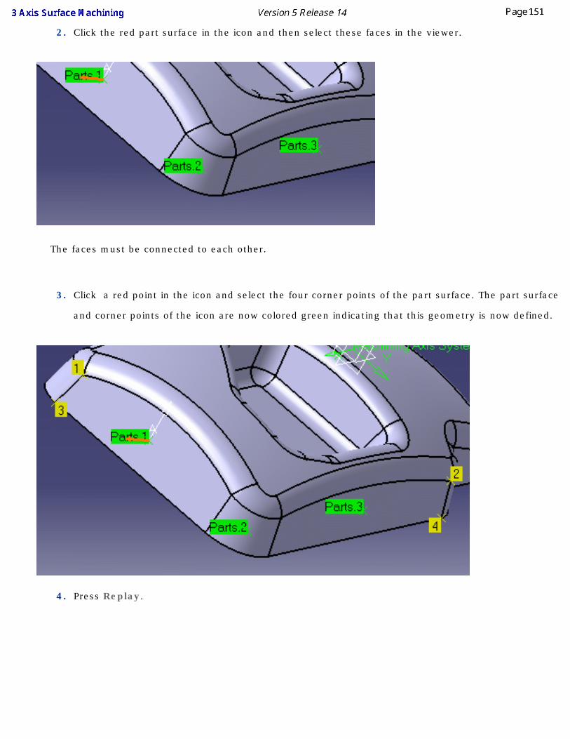
2. Click the red part surface in the icon and then select these faces in the viewer.
The faces must be connected to each other.
3. Click a red point in the icon and select the four corner points of the part surface. The part surface
and corner points of the icon are now colored green indicating that this geometry is now defined.
4. Press Replay.
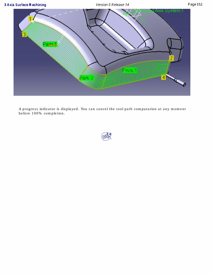
A progress indicator is displayed. You can cancel the tool path computation at any moment before 100% completion.
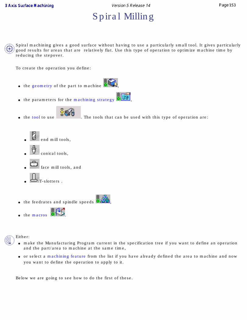
Spiral Milling
Spiral machining gives a good surface without having to use a particularly small tool. It gives particularly good results for areas that are relatively flat. Use this type of operation to optimize machine time by reducing the stepover.
To create the operation you define:
● the geometry of the part to machine ,
● the parameters for the machining strategy ,
● the tool to use . The tools that can be used with this type of operation are:
● end mill tools,
● conical tools,
● face mill tools, and
● T-slotters .
● the feedrates and spindle speeds ,
● the macros .
Either:
● make the Manufacturing Program current in the specification tree if you want to define an operation and the part/area to machine at the same time,
● or select a machining feature from the list if you have already defined the area to machine and now you want to define the operation to apply to it.
Below we are going to see how to do the first of these.
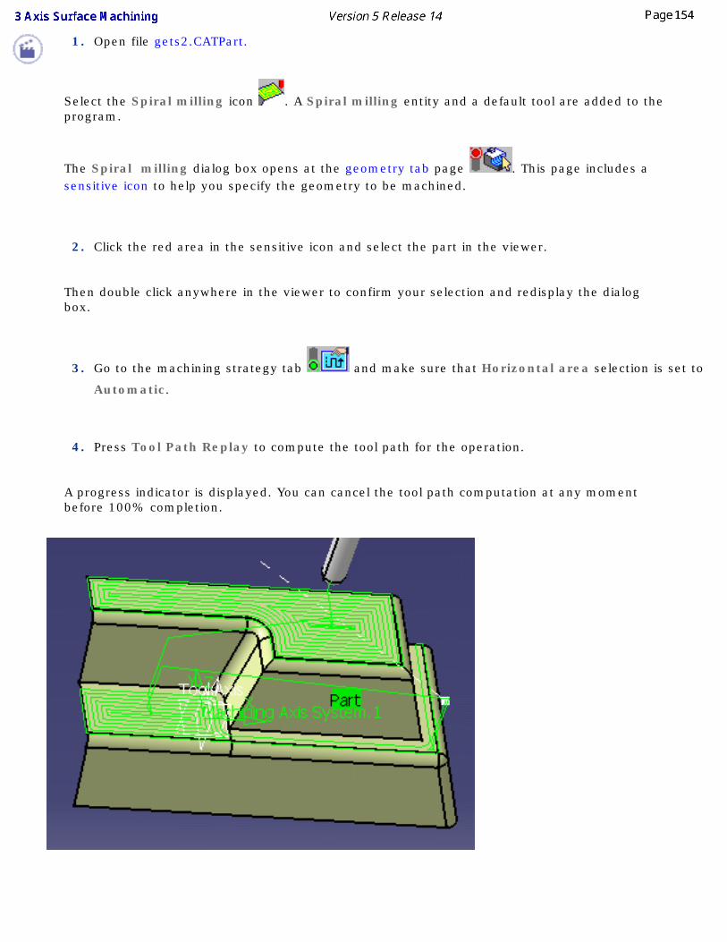
1. Open file gets2.CATPart.
Select the Spiral milling icon . A Spiral milling entity and a default tool are added to the program.
The Spiral milling dialog box opens at the geometry tab page . This page includes a sensitive icon to help you specify the geometry to be machined.
2. Click the red area in the sensitive icon and select the part in the viewer.
Then double click anywhere in the viewer to confirm your selection and redisplay the dialog box.
3. Go to the machining strategy tab and make sure that Horizontal area selection is set to
Automatic.
4. Press Tool Path Replay to compute the tool path for the operation.
A progress indicator is displayed. You can cancel the tool path computation at any moment before 100% completion.
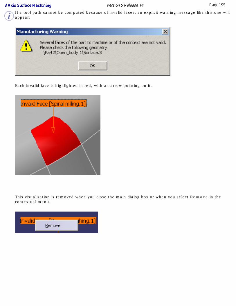
If a tool path cannot be computed because of invalid faces, an explicit warning message like this one will appear:
Each invalid face is highlighted in red, with an arrow pointing on it.
This visualization is removed when you close the main dialog box or when you select Remove in the contextual menu.
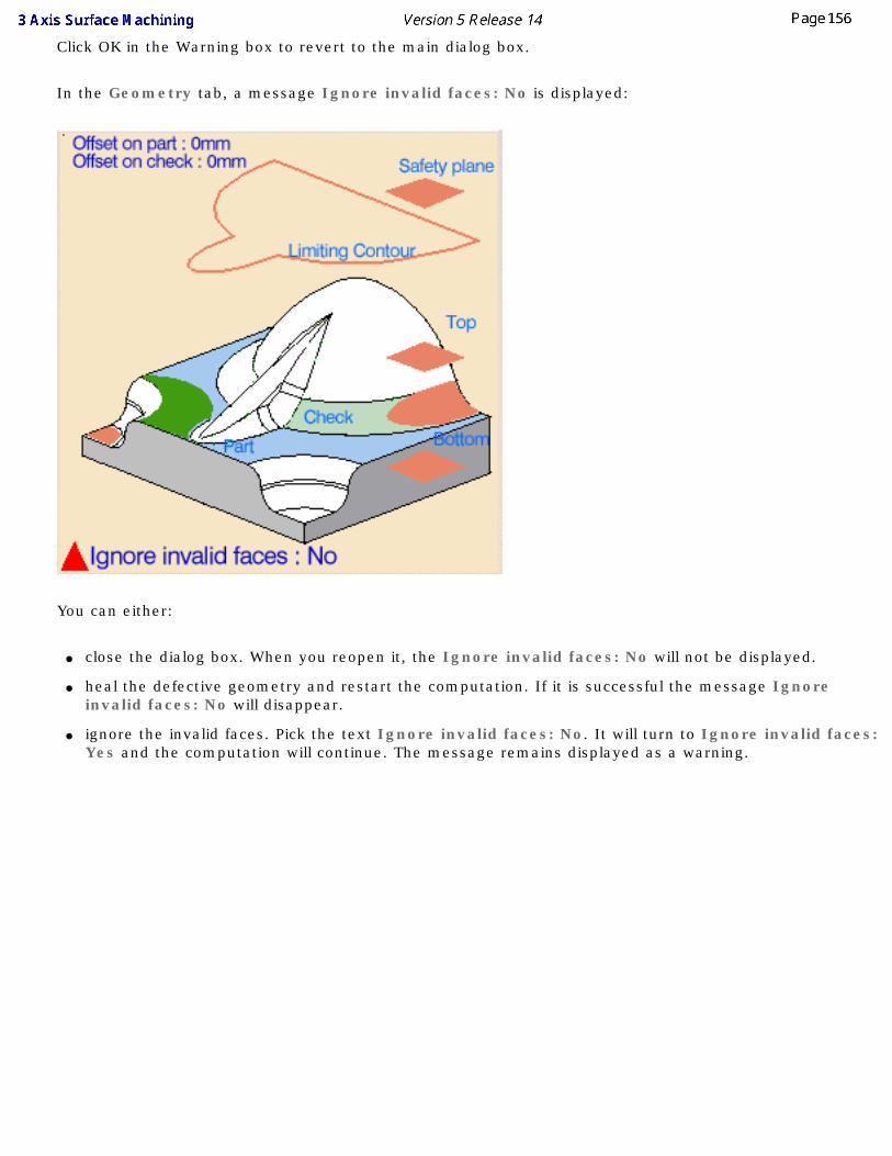
Click OK in the Warning box to revert to the main dialog box.
In the Geometry tab, a message Ignore invalid faces: No is displayed:
You can either:
● close the dialog box. When you reopen it, the Ignore invalid faces: No will not be displayed.
● heal the defective geometry and restart the computation. If it is successful the message Ignore invalid faces: No will disappear.
● ignore the invalid faces. Pick the text Ignore invalid faces: No. It will turn to Ignore invalid faces: Yes and the computation will continue. The message remains displayed as a warning.
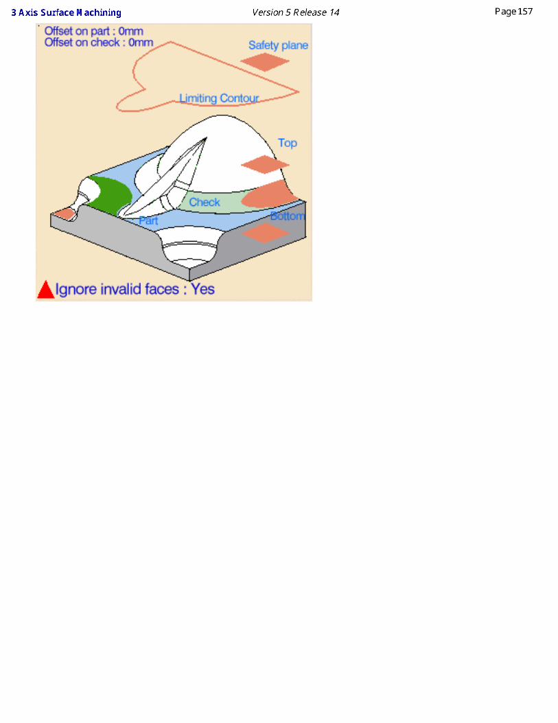
Create a Profile Contouring OperationThis task explains how to create a profile contouring operation on a part.
A profile contouring operation can be created from machining:
● Between two planesThe tool follows a contour between the top and bottom planes while respecting user-defined geometry limitations and machining strategy parameters.
● Between two curvesThe tool follows the trajectory defined by the top and bottom guide curves while respecting user-defined geometry limitations and machining strategy parameters.
● Between a curve and surfacesThe tool follows a trajectory defined by a top guide curve and the bottom surfaces while respecting user-defined geometry limitations and machining strategy parameters.
See the Prismatic Machining User's Guide for more information on these functions.
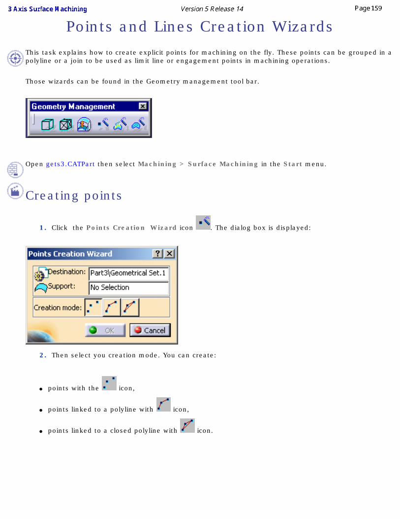
Points and Lines Creation WizardsThis task explains how to create explicit points for machining on the fly. These points can be grouped in a polyline or a join to be used as limit line or engagement points in machining operations.
Those wizards can be found in the Geometry management tool bar.
Open gets3.CATPart then select Machining > Surface Machining in the Start menu.
Creating points
1. Click the Points Creation Wizard icon . The dialog box is displayed:
2. Then select you creation mode. You can create:
● points with the icon,
● points linked to a polyline with icon,
● points linked to a closed polyline with icon.
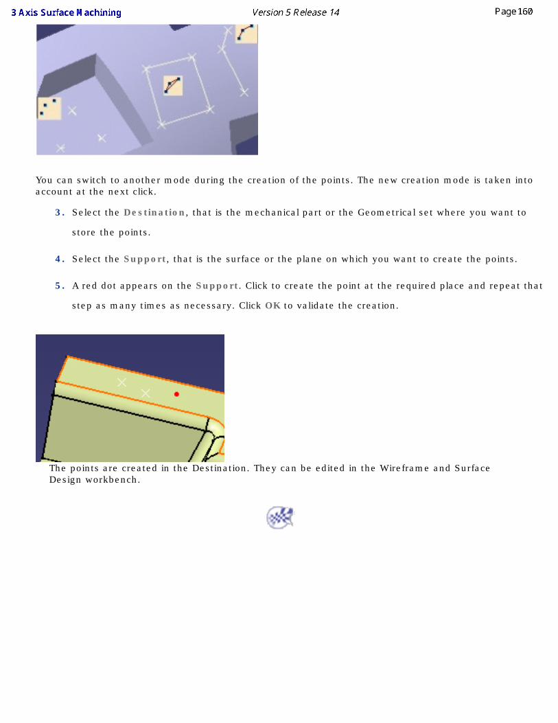
You can switch to another mode during the creation of the points. The new creation mode is taken into account at the next click.
3. Select the Destination, that is the mechanical part or the Geometrical set where you want to
store the points.
4. Select the Support, that is the surface or the plane on which you want to create the points.
5. A red dot appears on the Support. Click to create the point at the required place and repeat that
step as many times as necessary. Click OK to validate the creation.
The points are created in the Destination. They can be edited in the Wireframe and Surface Design workbench.
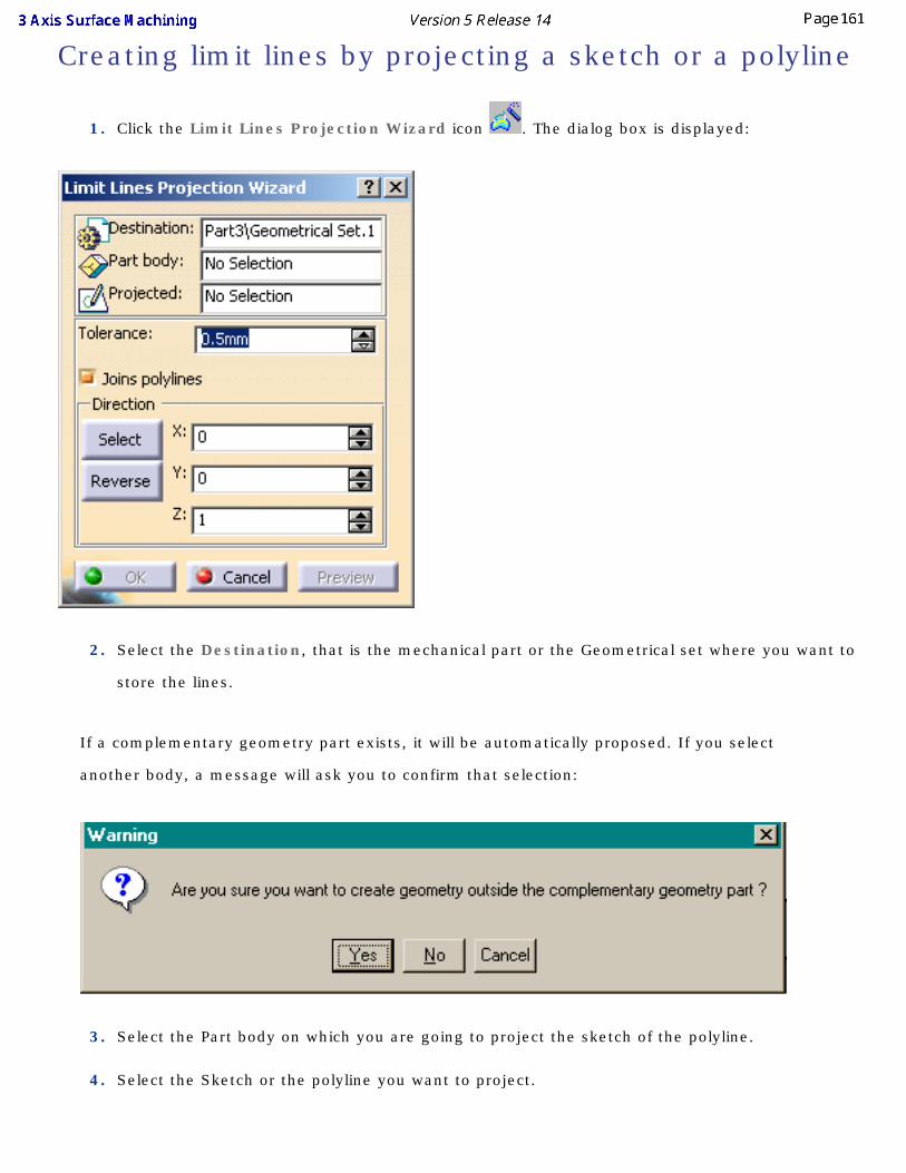
Creating limit lines by projecting a sketch or a polyline
1. Click the Limit Lines Projection Wizard icon . The dialog box is displayed:
2. Select the Destination, that is the mechanical part or the Geometrical set where you want to
store the lines.
If a complementary geometry part exists, it will be automatically proposed. If you select
another body, a message will ask you to confirm that selection:
3. Select the Part body on which you are going to project the sketch of the polyline.
4. Select the Sketch or the polyline you want to project.
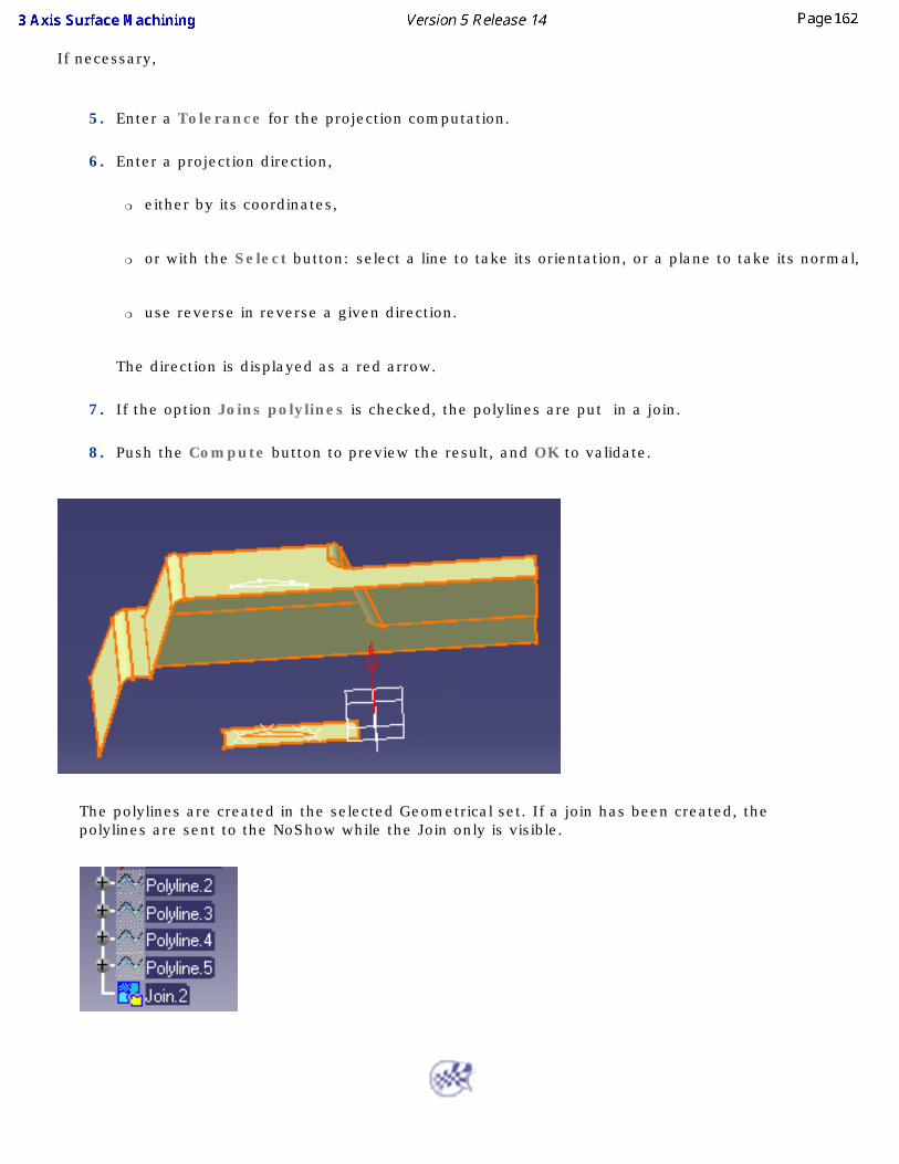
If necessary,
5. Enter a Tolerance for the projection computation.
6. Enter a projection direction,
❍ either by its coordinates,
❍ or with the Select button: select a line to take its orientation, or a plane to take its normal,
❍ use reverse in reverse a given direction.
The direction is displayed as a red arrow.
7. If the option Joins polylines is checked, the polylines are put in a join.
8. Push the Compute button to preview the result, and OK to validate.
The polylines are created in the selected Geometrical set. If a join has been created, the polylines are sent to the NoShow while the Join only is visible.
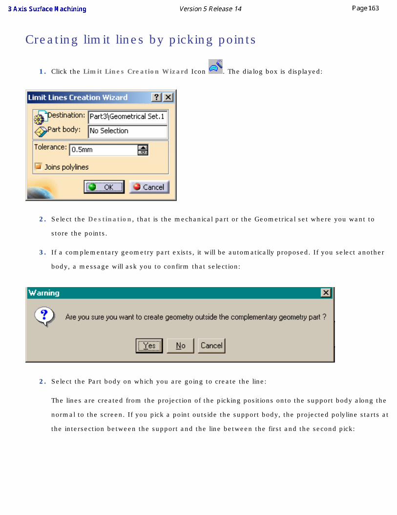
Creating limit lines by picking points
1. Click the Limit Lines Creation Wizard Icon . The dialog box is displayed:
2. Select the Destination, that is the mechanical part or the Geometrical set where you want to
store the points.
3. If a complementary geometry part exists, it will be automatically proposed. If you select another
body, a message will ask you to confirm that selection:
2. Select the Part body on which you are going to create the line:
The lines are created from the projection of the picking positions onto the support body along the
normal to the screen. If you pick a point outside the support body, the projected polyline starts at
the intersection between the support and the line between the first and the second pick:
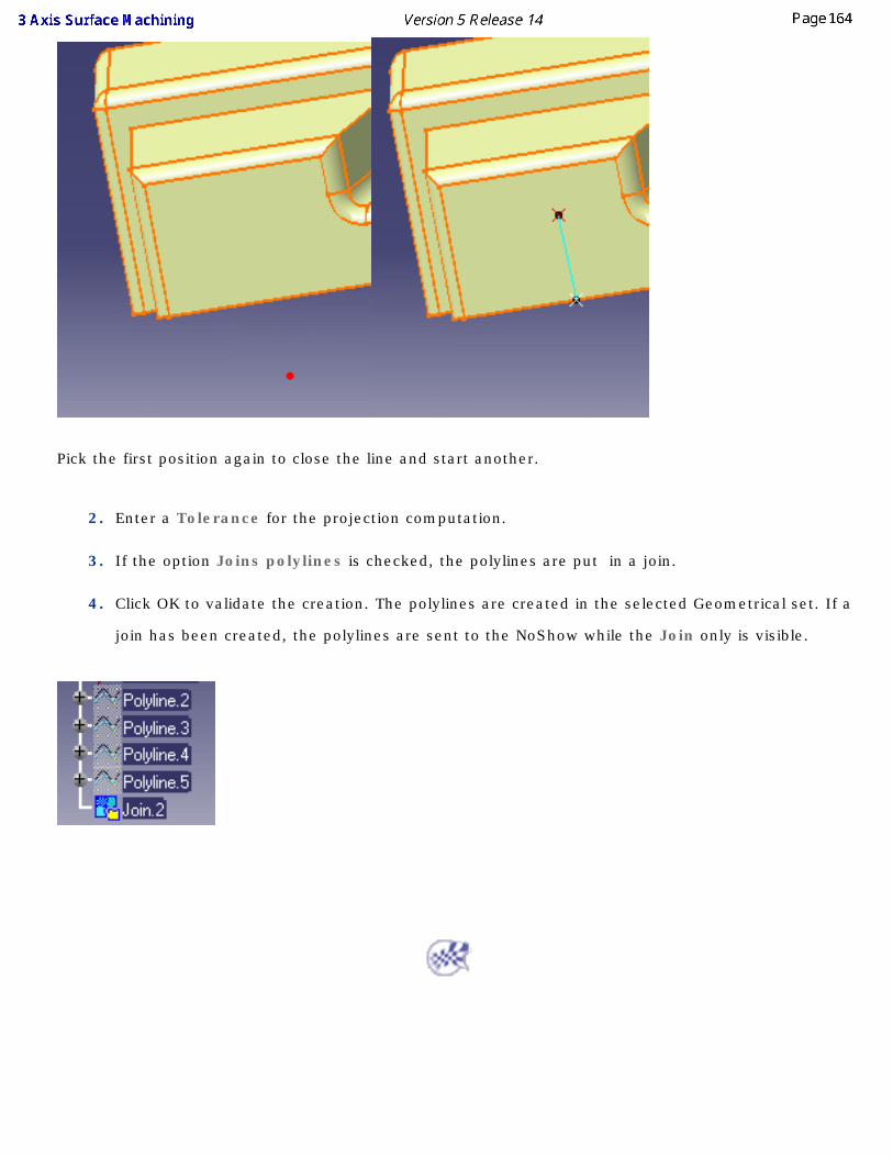
Pick the first position again to close the line and start another.
2. Enter a Tolerance for the projection computation.
3. If the option Joins polylines is checked, the polylines are put in a join.
4. Click OK to validate the creation. The polylines are created in the selected Geometrical set. If a
join has been created, the polylines are sent to the NoShow while the Join only is visible.
Reworking Operations These are the tasks that you will use to rework an area on a part where there is residual material. Before using one of these operations, compute the areas that you want to rework.
Create a pencil operation: ● Select the pencil icon,
● Choose a part to machine,
● Specify the tool to be used.
You can also specify machining parameters, feedrates and spindle speeds and macro data.Create a reworking operation:
● Select the Roughing icon,
● Choose a part to machine
● Specify the tool to be used,
● Specify the type of roughing.
You can also specify machining parameters, feedrates and spindle speeds and macro data.Basic tasks illustrate:
● a Pencil operation,
● a Reworking operation
Pencil Operations This task shows you how to insert a pencil operation into the program. A pencil operation is one where the tool remains tangent in two places to the surface to be machined during the cycle. It is often used to remove crests along the intersection of two surfaces that were left behind by a previous operation.
To create the operation you define:
● the geometry of the part to machine ,
● the parameters of the machining strategy ,
● the tool to use ; you have the choice of end mill or conical tools for this operation,
● the feedrates and spindle speeds,
● the macros .
Only the geometry is obligatory, all of the other parameters have a default value.
Either:
● make the Manufacturing Program current in the specification tree if you want to define an operation and the part/area to machine at the same time,
● or select a machining feature from the list if you have already defined the area to machine and now you want to define the operation to apply to it.
Below we are going to see how to do the first of these.
1. Open file gets2.CATPart.
A Pencil entity and a default tool have been added to the program.
Select the Pencil icon . The dialog box opens at the geometry page . This page includes a sensitive icon to help you specify the geometry to be machined.
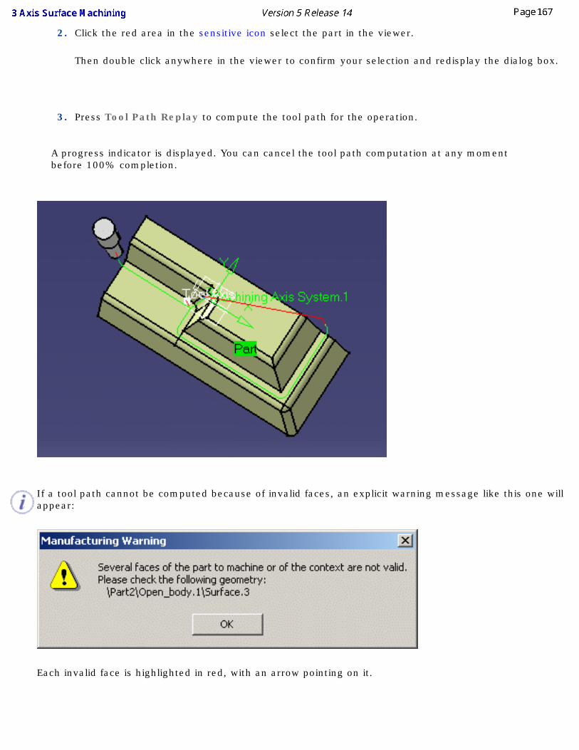
2. Click the red area in the sensitive icon select the part in the viewer.
Then double click anywhere in the viewer to confirm your selection and redisplay the dialog box.
3. Press Tool Path Replay to compute the tool path for the operation.
A progress indicator is displayed. You can cancel the tool path computation at any moment before 100% completion.
If a tool path cannot be computed because of invalid faces, an explicit warning message like this one will appear:
Each invalid face is highlighted in red, with an arrow pointing on it.
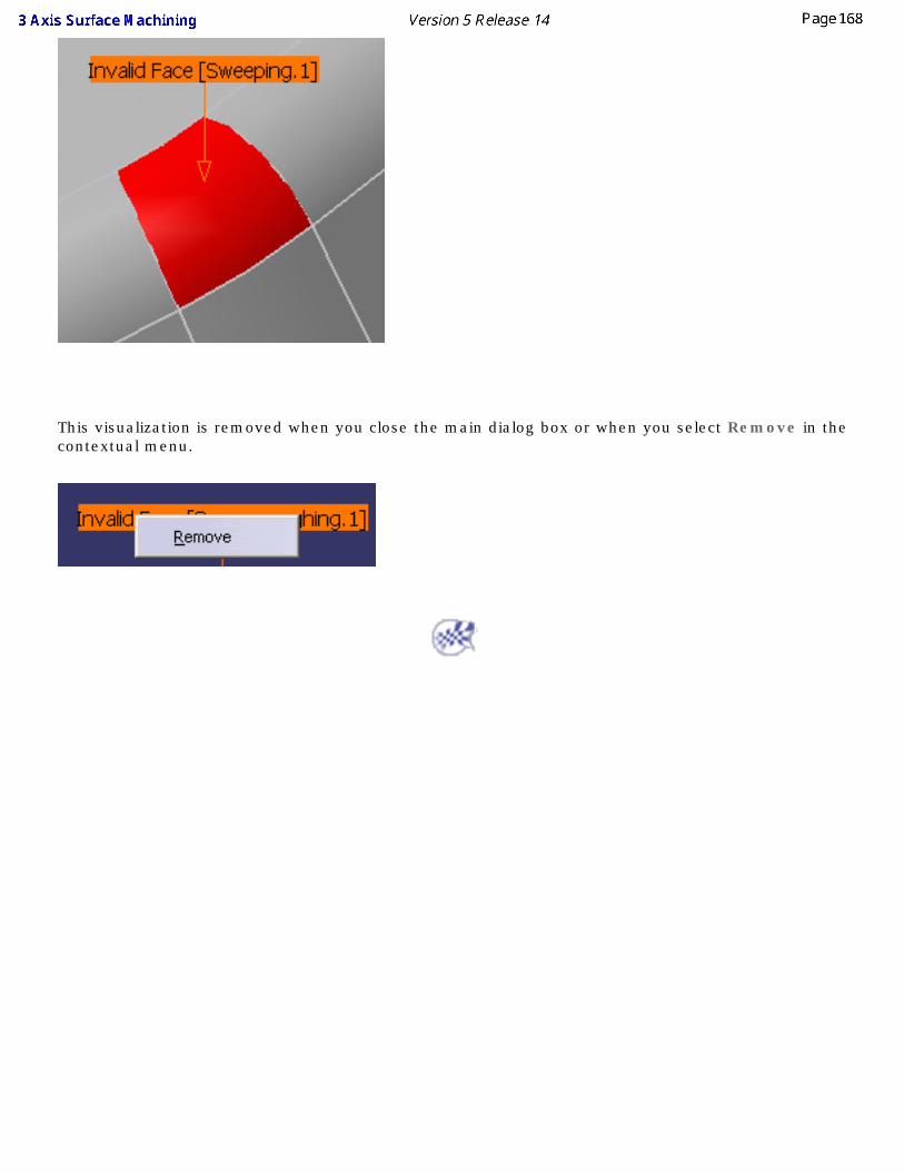
This visualization is removed when you close the main dialog box or when you select Remove in the contextual menu.
Roughing Rework Operations This task explains how to rework a part.
You must have defined a rough stock in the part operation. A rough stock that is defined in the part operation before starting the definition of the Manufacturing Program will be used for all of the successive operations, each working on the residual material left by the operation before it.
You must have computed at least one machining operation prior to this one in the Manufacturing Program.
The rough stock used for a program where you insert a reworking operation must be topologically closed, that is, it cannot be formed by a set of faces.
Roughing rework does not function correctly if you have a rough stock in several parts because the rework rough stock will be defined as the containment box around them.
In order to simplify the scenario, the sample given below already contains a rough stock.
1. Open the Basic.CATProcess file.
Select Rough stock in the Product list and hide it using the Hide/Show option in the contextual menu.
Fully expand the Manufacturing Program. You will see that a first roughing operation has already been effected. Select that operation.
Select the Roughing icon . The dialog box opens at the Geometry tab .
2. Click the red area in the sensitive icon and select the part in the viewer.
Then double click anywhere in the viewer to confirm your selection and redisplay the dialog box.
3. Go to the Tool tab .
Push this button and choose the tool called T2 End Mill D 5 in the dialog box that is displayed.
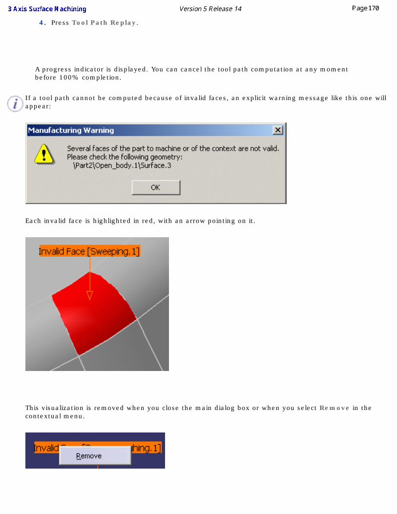
4. Press Tool Path Replay.
A progress indicator is displayed. You can cancel the tool path computation at any moment before 100% completion.
If a tool path cannot be computed because of invalid faces, an explicit warning message like this one will appear:
Each invalid face is highlighted in red, with an arrow pointing on it.
This visualization is removed when you close the main dialog box or when you select Remove in the contextual menu.
5. You can, if you wish, modify any of the other parameters:
● geometry
● machining strategy,
● speeds and rates,
● macro data,
● the type or size of tool used.
in the dialog box but this is not obligatory as they all have default values.
Machining FeaturesMachining features are areas that you define on a part. You may want to define an area where you want to use a specific type of operation or you may want to define an area to rework because there is too much residual material on the part.
Besides this, you can also decide to define a specific offset on an area of a part or a group of varied offsets on a part.
Area to machine
Area to rework
Offset Group
Useful information can also be found in the Using Geometrical Areas chapter.
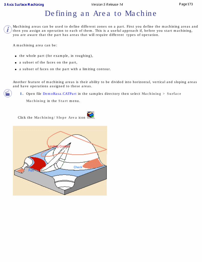
Defining an Area to MachineMachining areas can be used to define different zones on a part. First you define the machining areas and then you assign an operation to each of them. This is a useful approach if, before you start machining, you are aware that the part has areas that will require different types of operation.
A machining area can be:
● the whole part (for example, in roughing),
● a subset of the faces on the part,
● a subset of faces on the part with a limiting contour.
Another feature of machining areas is their ability to be divided into horizontal, vertical and sloping areas and have operations assigned to these areas.
1. Open file DemoRasa.CATPart in the samples directory then select Machining > Surface
Machining in the Start menu.
Click the Machining/Slope Area icon .
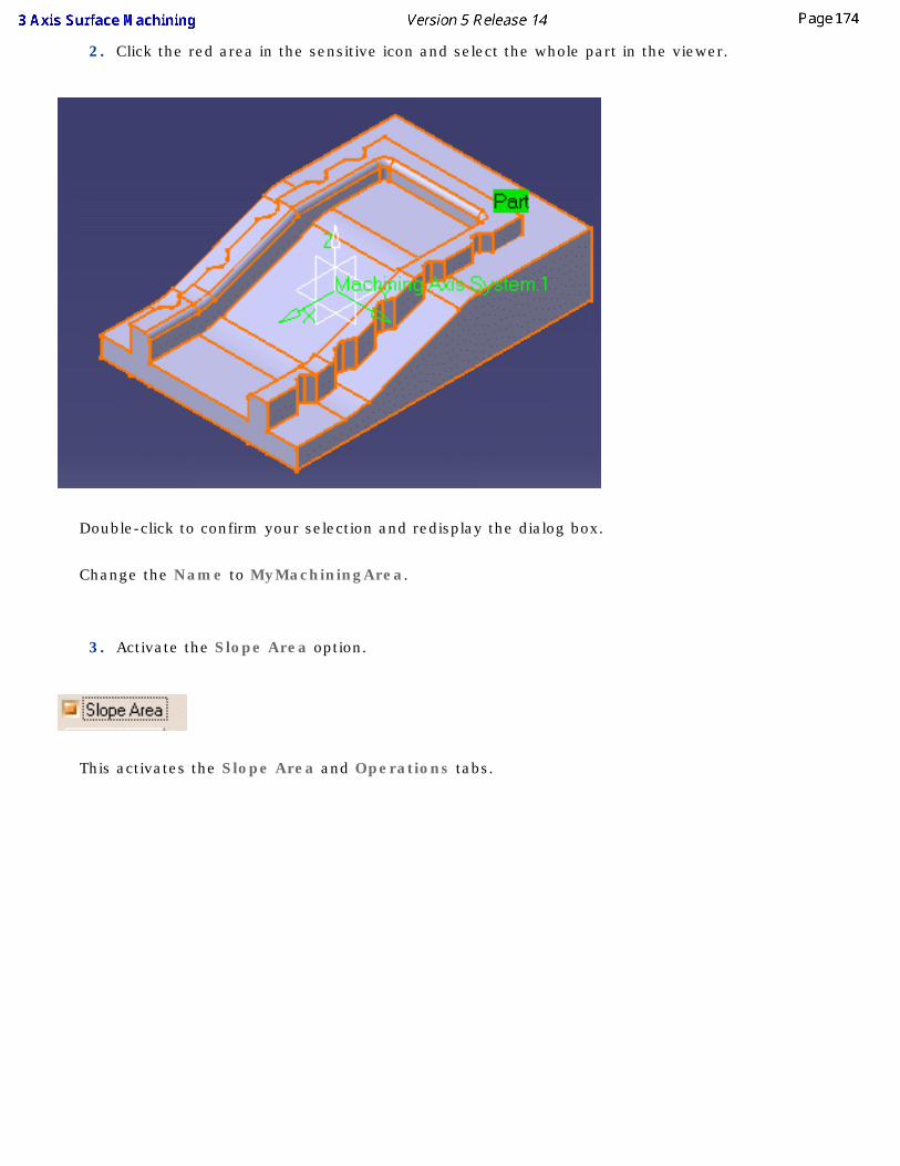
2. Click the red area in the sensitive icon and select the whole part in the viewer.
Double-click to confirm your selection and redisplay the dialog box.
Change the Name to MyMachiningArea.
3. Activate the Slope Area option.
This activates the Slope Area and Operations tabs.
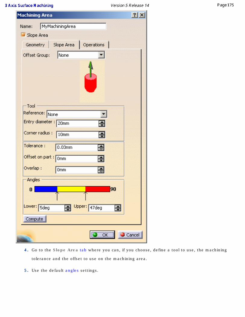
4. Go to the Slope Area tab where you can, if you choose, define a tool to use, the machining
tolerance and the offset to use on the machining area.
5. Use the default angles settings.
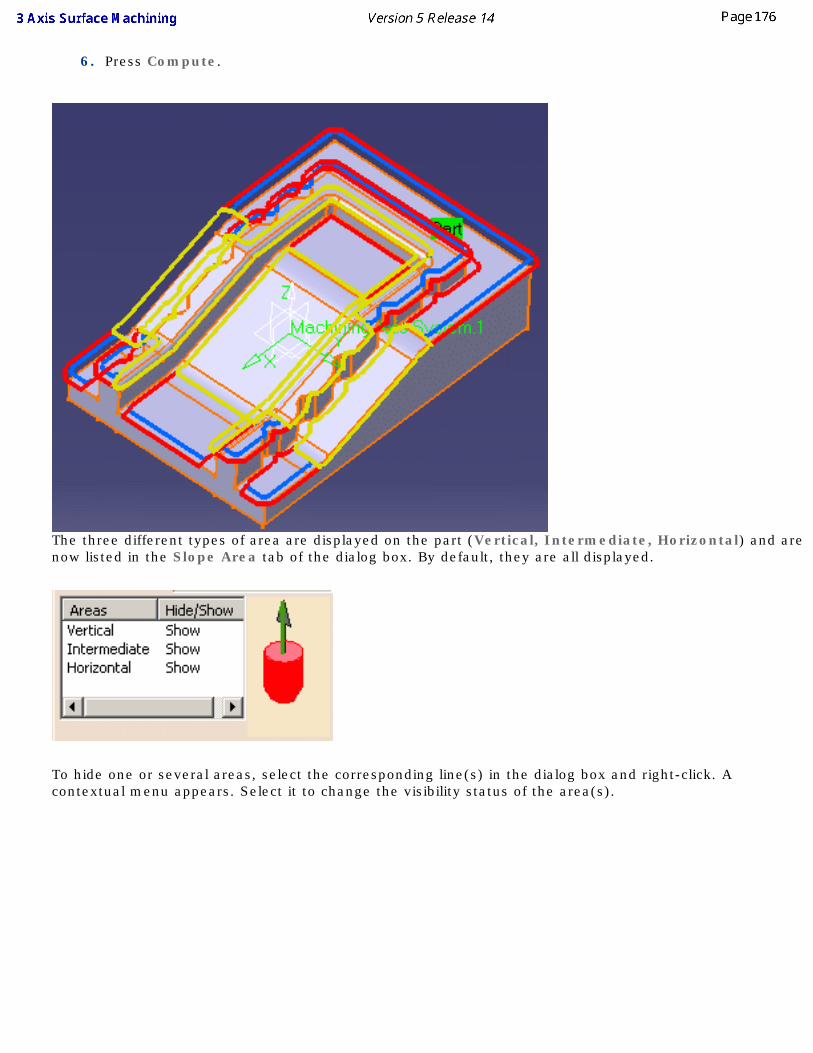
6. Press Compute.
The three different types of area are displayed on the part (Vertical, Intermediate, Horizontal) and are now listed in the Slope Area tab of the dialog box. By default, they are all displayed.
To hide one or several areas, select the corresponding line(s) in the dialog box and right-click. A contextual menu appears. Select it to change the visibility status of the area(s).
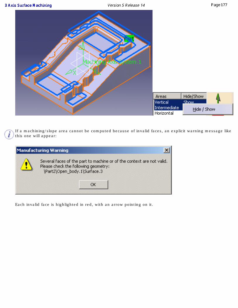
If a machining/slope area cannot be computed because of invalid faces, an explicit warning message like this one will appear:
Each invalid face is highlighted in red, with an arrow pointing on it.
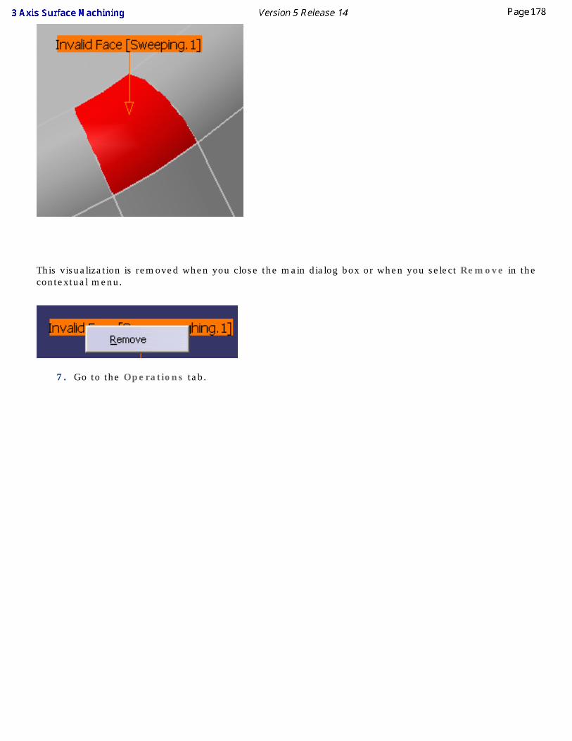
This visualization is removed when you close the main dialog box or when you select Remove in the contextual menu.
7. Go to the Operations tab.
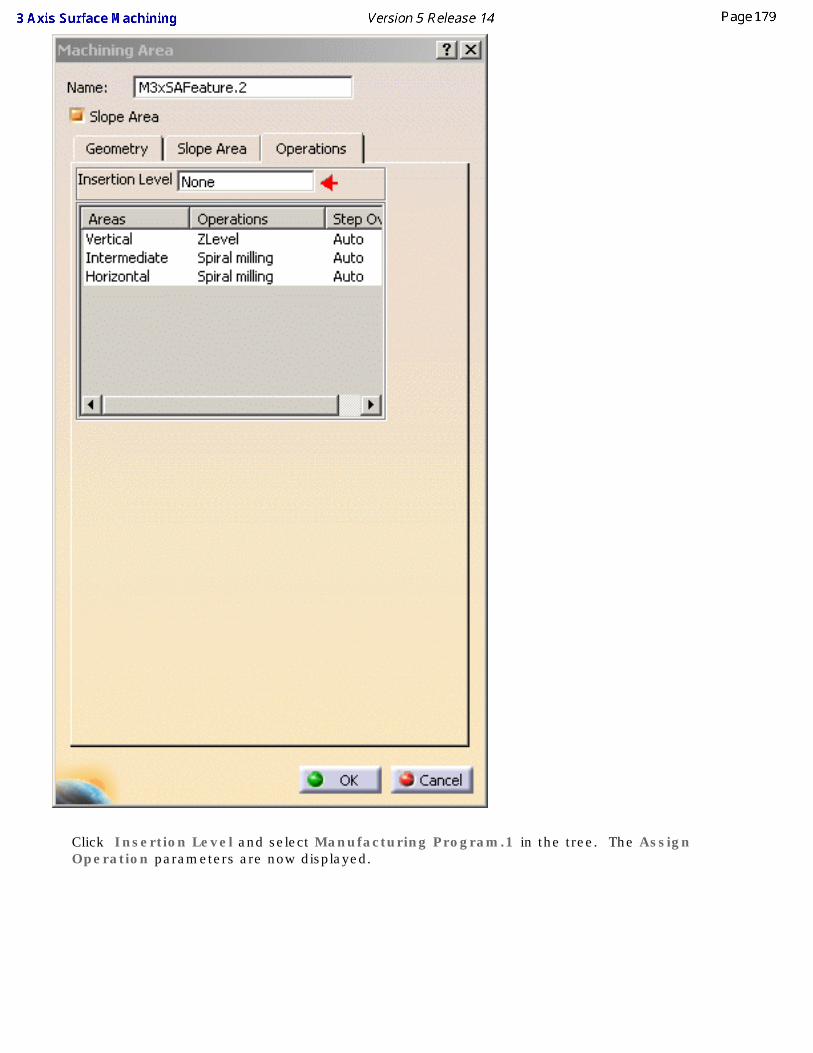
Click Insertion Level and select Manufacturing Program.1 in the tree. The Assign Operation parameters are now displayed.
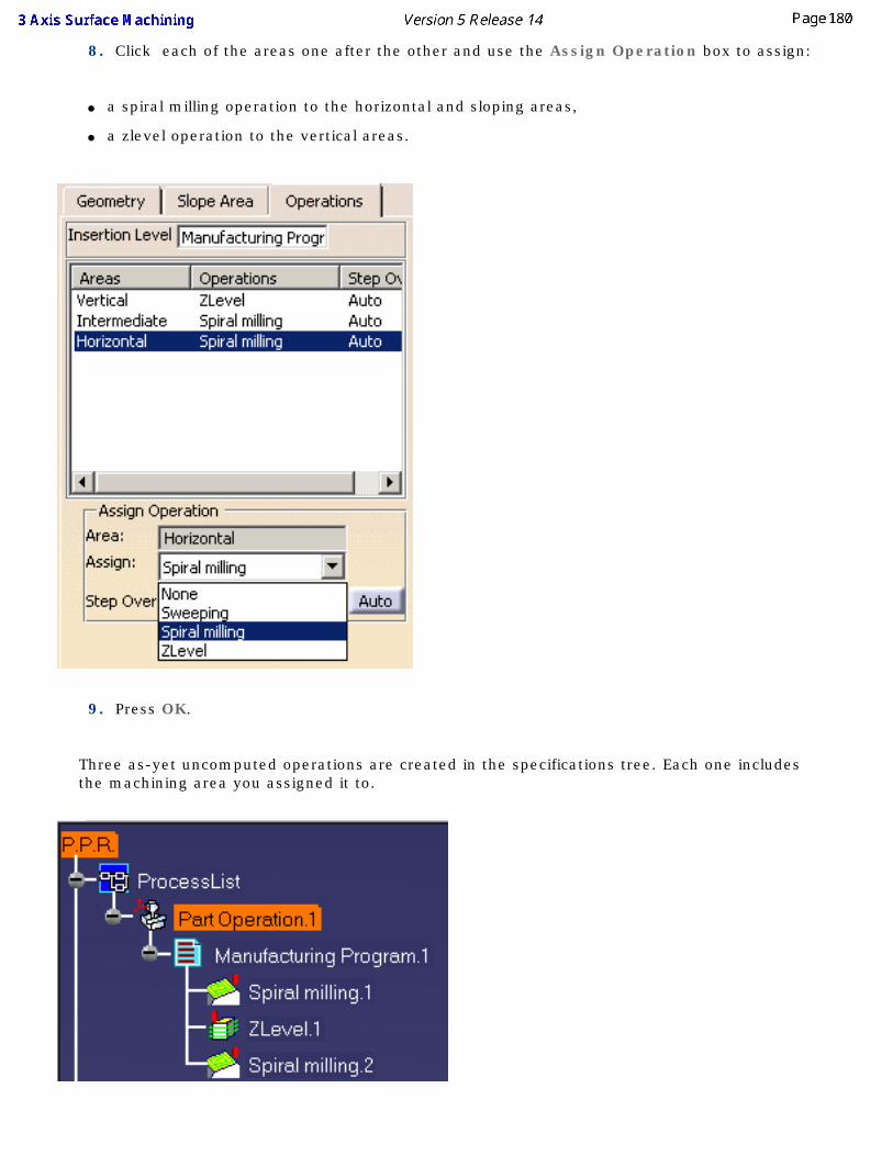
8. Click each of the areas one after the other and use the Assign Operation box to assign:
● a spiral milling operation to the horizontal and sloping areas,
● a zlevel operation to the vertical areas.
9. Press OK.
Three as-yet uncomputed operations are created in the specifications tree. Each one includes the machining area you assigned it to.
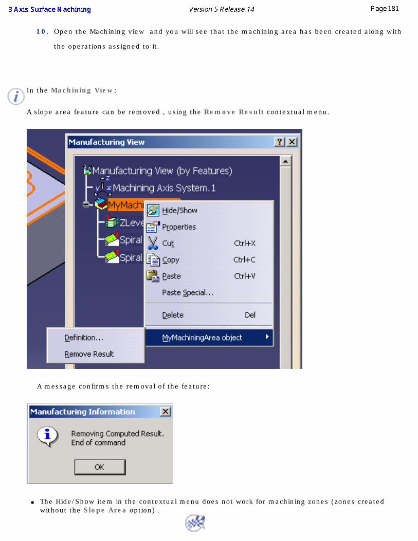
10. Open the Machining view and you will see that the machining area has been created along with
the operations assigned to it.
In the Machining View:
A slope area feature can be removed , using the Remove Result contextual menu.
A message confirms the removal of the feature:
● The Hide/Show item in the contextual menu does not work for machining zones (zones created without the Slope Area option) .
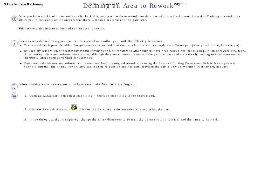
Defining an Area to ReworkOnce you have machined a part and visually checked it, you may decide to rework certain areas where residual material remains. Defining a rework area allows you to focus only on the areas where there is residual material and this gain time.
This task explains how to define and edit an area to rework.
Rework areas defined on a given part can be re-used on another part, with the following limitations:
● This re-usability is possible with a design change (i.e. evolution of the part) but not with a completely different part (from punch to die, for example).
● Re-usability is more uncertain if many manual divisions and/or transfers to other subsets have been carried out for the computation of rework area takes those cutting points and subsets into account, although they are no longer relevant if the part has changed dramatically, leading to incoherent results (horizontal areas seen as vertical, for example).
● Those manual divisions and subsets can be removed from the original rework area using the Remove Cutting Points and Delete Non-updated Subsets buttons. The original rework area can then be re-used on another part, provided the part is only an evolution from the original one.
Before creating a rework area you must have executed a Manufacturing Program.
1. Open gets2.CATPart then select Machining > Surface Machining in the Start menu.
2. Click the Rework Area icon . Click on the Part area in the sensitive icon and select the part.
3. In the dialog box that is displayed, change the Entry diameter to 10 mm, the Corner radius to 5 mm and the name to Rework.
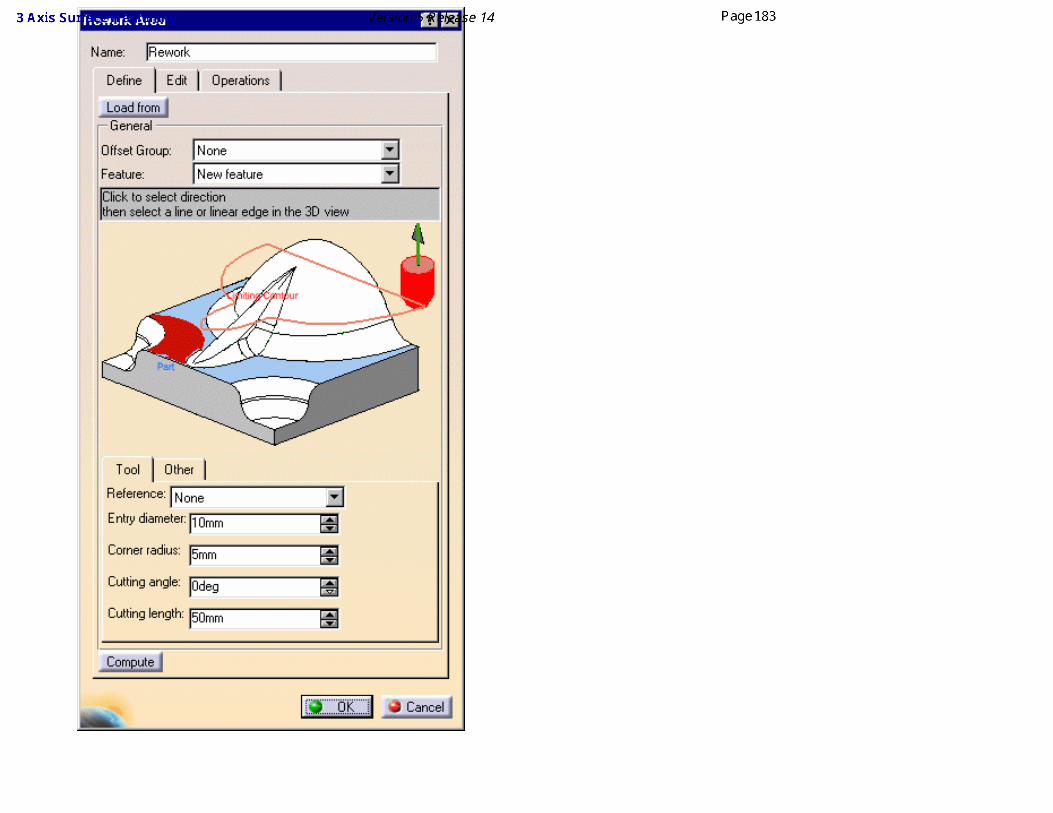
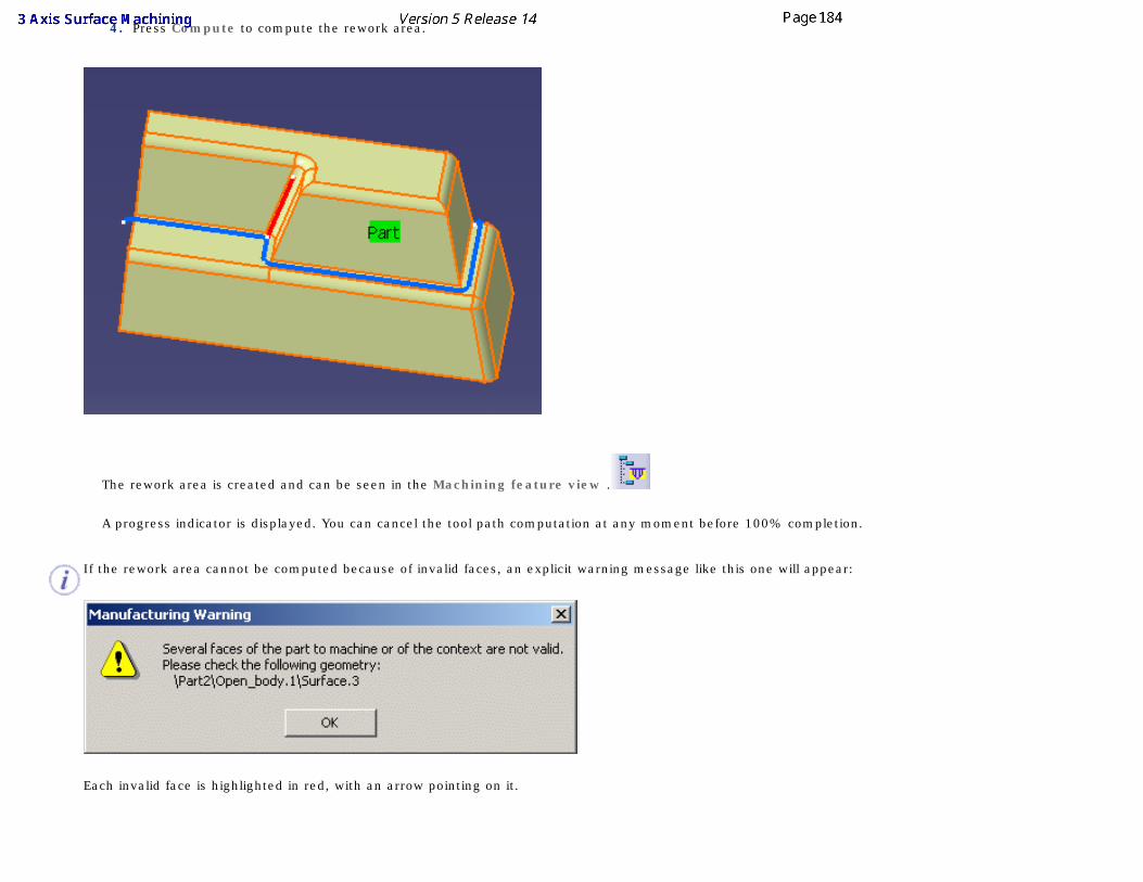
4. Press Compute to compute the rework area.
The rework area is created and can be seen in the Machining feature view .
A progress indicator is displayed. You can cancel the tool path computation at any moment before 100% completion.
If the rework area cannot be computed because of invalid faces, an explicit warning message like this one will appear:
Each invalid face is highlighted in red, with an arrow pointing on it.
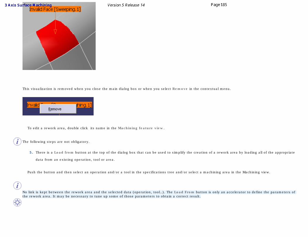
This visualization is removed when you close the main dialog box or when you select Remove in the contextual menu.
To edit a rework area, double click its name in the Machining feature view.
The following steps are not obligatory.
5. There is a Load from button at the top of the dialog box that can be used to simplify the creation of a rework area by loading all of the appropriate
data from an existing operation, tool or area.
Push the button and then select an operation and/or a tool in the specifications tree and/or select a machining area in the Machining view.
No link is kept between the rework area and the selected data (operation, tool..). The Load From button is only an accelerator to define the parameters of the rework area. It may be necessary to tune up some of those parameters to obtain a correct result.
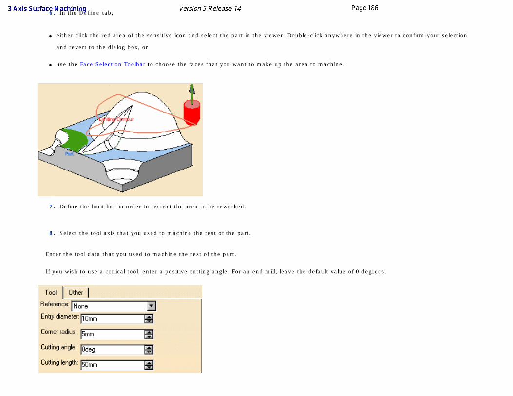
6. In the Define tab,
● either click the red area of the sensitive icon and select the part in the viewer. Double-click anywhere in the viewer to confirm your selection
and revert to the dialog box, or
● use the Face Selection Toolbar to choose the faces that you want to make up the area to machine.
7. Define the limit line in order to restrict the area to be reworked.
8. Select the tool axis that you used to machine the rest of the part.
Enter the tool data that you used to machine the rest of the part.
If you wish to use a conical tool, enter a positive cutting angle. For an end mill, leave the default value of 0 degrees.
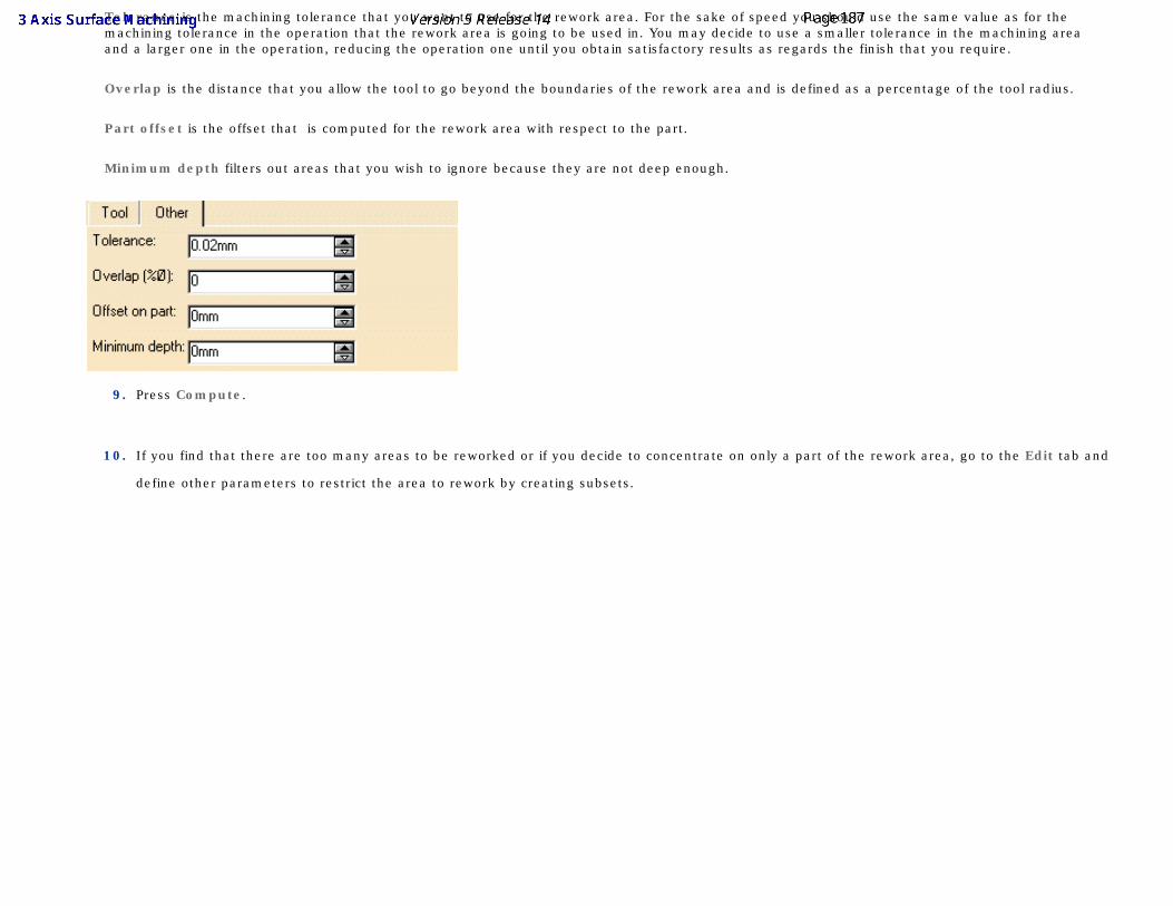
Tolerance is the machining tolerance that you want to use for the rework area. For the sake of speed you should use the same value as for the machining tolerance in the operation that the rework area is going to be used in. You may decide to use a smaller tolerance in the machining area and a larger one in the operation, reducing the operation one until you obtain satisfactory results as regards the finish that you require.
Overlap is the distance that you allow the tool to go beyond the boundaries of the rework area and is defined as a percentage of the tool radius.
Part offset is the offset that is computed for the rework area with respect to the part.
Minimum depth filters out areas that you wish to ignore because they are not deep enough.
9. Press Compute.
10. If you find that there are too many areas to be reworked or if you decide to concentrate on only a part of the rework area, go to the Edit tab and
define other parameters to restrict the area to rework by creating subsets.
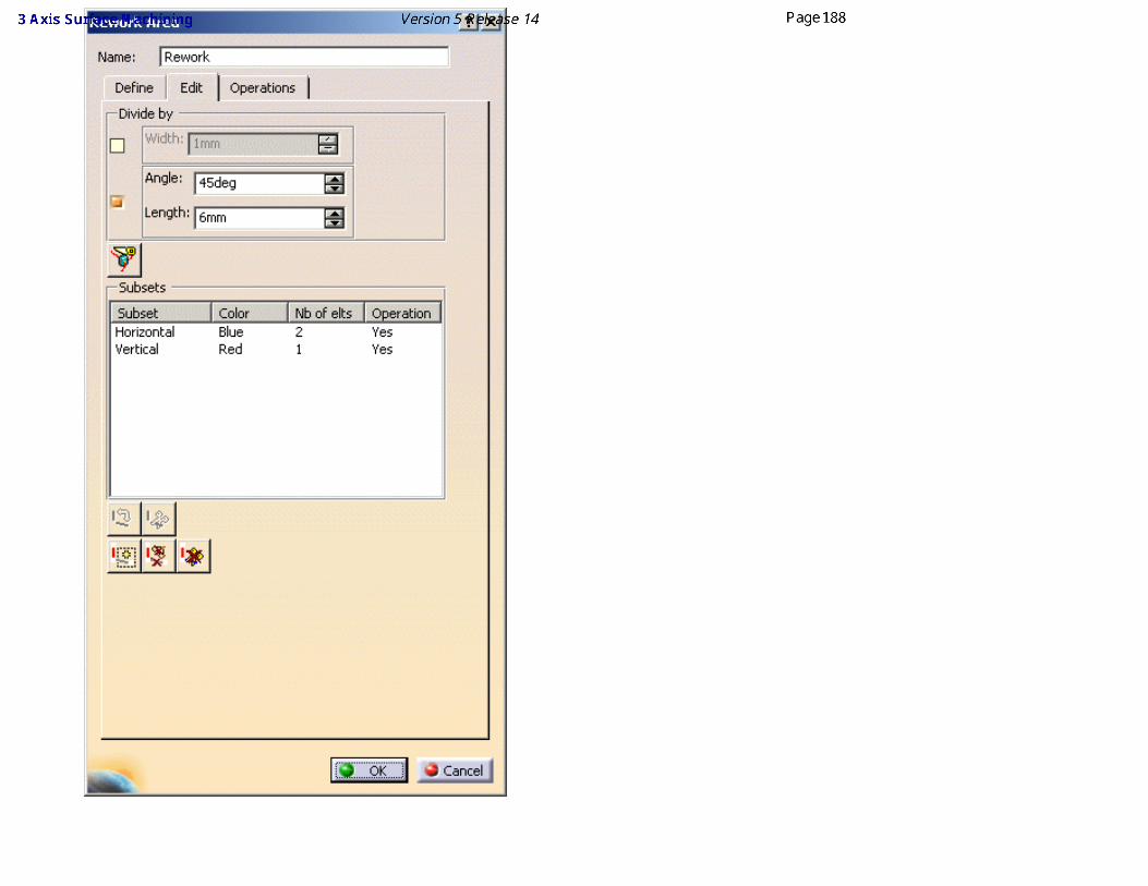
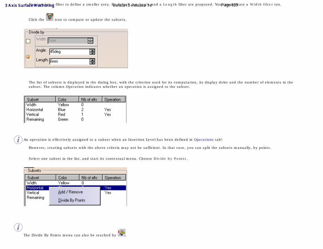
You can use a filter to define a smaller area. By default, an Angle and a Length filter are proposed. You can activate a Width filter too.
Click the icon to compute or update the subsets.
The list of subsets is displayed in the dialog box, with the criterion used for its computation, its display dolor and the number of elements in the subset. The column Operation indicates whether an operation is assigned to the subset.
An operation is effectively assigned to a subset when an Insertion Level has been defined in Operations tab!
However, creating subsets with the above criteria may not be sufficient. In that case, you can split the subsets manually, by points.
Select one subset in the list, and start its contextual menu. Choose Divide by Points.
The Divide By Points menu can also be reached by .
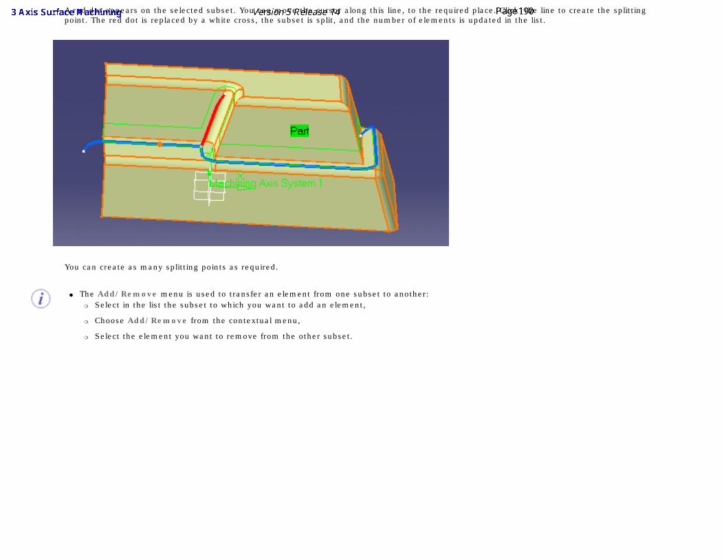
A red dot appears on the selected subset. You can move the cursor along this line, to the required place. Click the line to create the splitting point. The red dot is replaced by a white cross, the subset is split, and the number of elements is updated in the list.
You can create as many splitting points as required.
● The Add/Remove menu is used to transfer an element from one subset to another: ❍ Select in the list the subset to which you want to add an element,
❍ Choose Add/Remove from the contextual menu,
❍ Select the element you want to remove from the other subset.
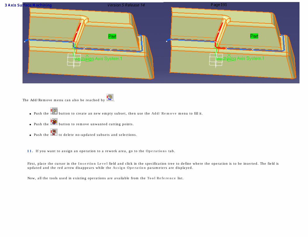
The Add/Remove menu can also be reached by .
● Push the button to create an new empty subset, then use the Add/Remove menu to fill it.
● Push the button to remove unwanted cutting points.
● Push the to delete no-updated subsets and selections.
11. If you want to assign an operation to a rework area, go to the Operations tab.
First, place the cursor in the Insertion Level field and click in the specification tree to define where the operation is to be inserted. The field is updated and the red arrow disappears while the Assign Operation parameters are displayed.
Now, all the tools used in existing operations are available from the Tool Reference list.
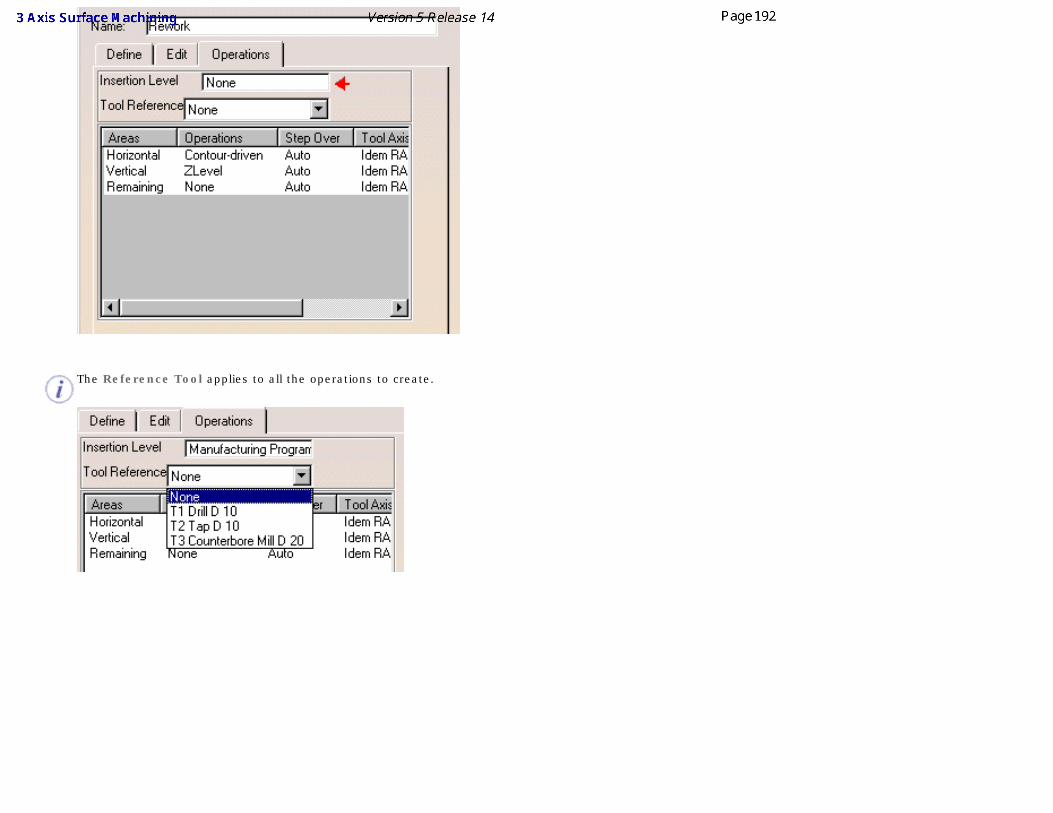
The Reference Tool applies to all the operations to create.
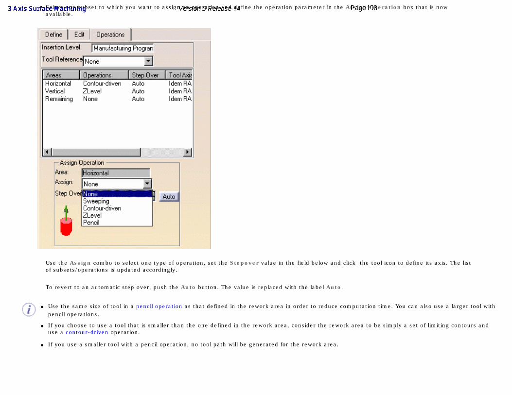
Select one subset to which you want to assign an operation and define the operation parameter in the Assign Operation box that is now available.
Use the Assign combo to select one type of operation, set the Stepover value in the field below and click the tool icon to define its axis. The list of subsets/operations is updated accordingly.
To revert to an automatic step over, push the Auto button. The value is replaced with the label Auto.
● Use the same size of tool in a pencil operation as that defined in the rework area in order to reduce computation time. You can also use a larger tool with pencil operations.
● If you choose to use a tool that is smaller than the one defined in the rework area, consider the rework area to be simply a set of limiting contours and use a contour-driven operation.
● If you use a smaller tool with a pencil operation, no tool path will be generated for the rework area.
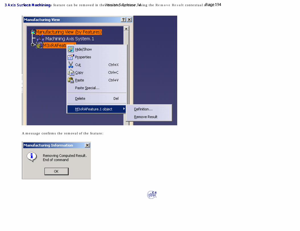
● A rework area feature can be removed in the Machining View, using the Remove Result contextual menu.
A message confirms the removal of the feature:
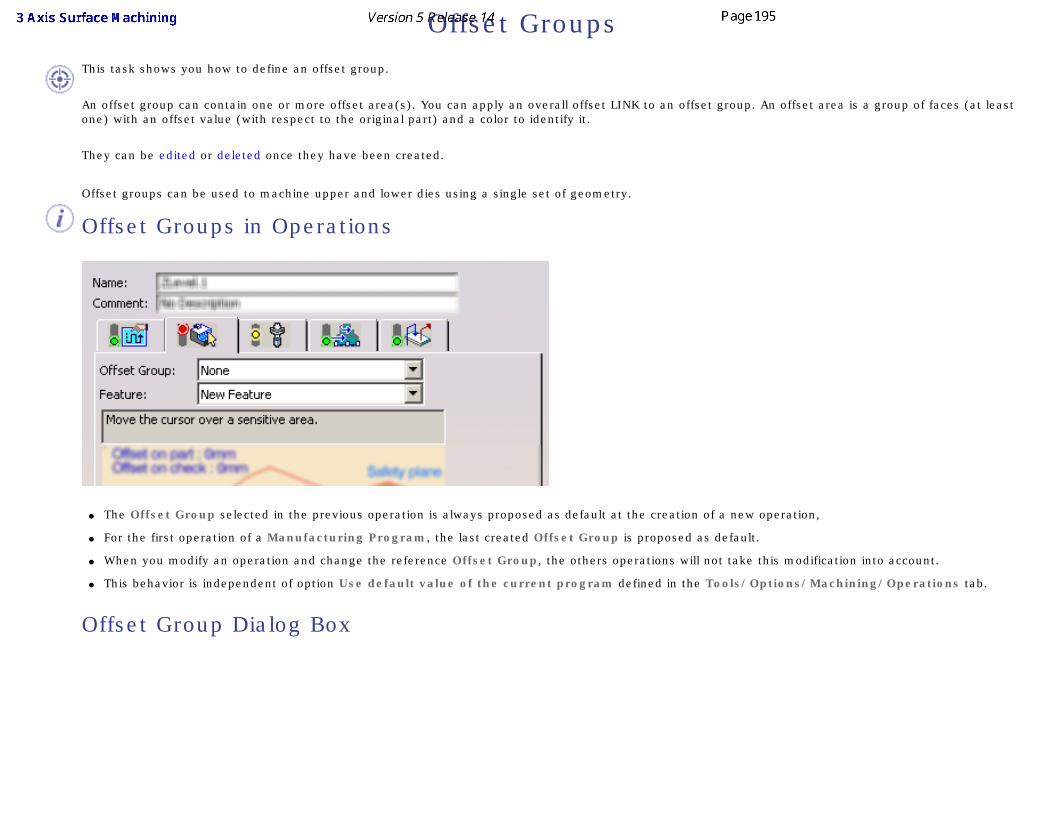
Offset Groups
This task shows you how to define an offset group.
An offset group can contain one or more offset area(s). You can apply an overall offset LINK to an offset group. An offset area is a group of faces (at least one) with an offset value (with respect to the original part) and a color to identify it.
They can be edited or deleted once they have been created.
Offset groups can be used to machine upper and lower dies using a single set of geometry.
Offset Groups in Operations
● The Offset Group selected in the previous operation is always proposed as default at the creation of a new operation,
● For the first operation of a Manufacturing Program, the last created Offset Group is proposed as default.
● When you modify an operation and change the reference Offset Group, the others operations will not take this modification into account.
● This behavior is independent of option Use default value of the current program defined in the Tools/Options/Machining/Operations tab.
Offset Group Dialog Box

● Offset Global in the upper part of the dialog box is the overall offset that will be applied to the group in general. However, it is applied only to offset areas in the offset group that do not have their own specific offset.
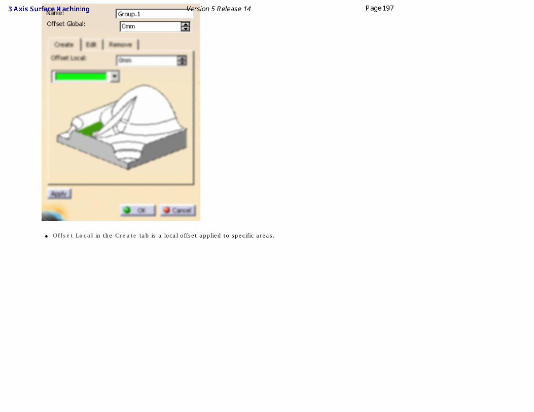
● Offset Local in the Create tab is a local offset applied to specific areas.
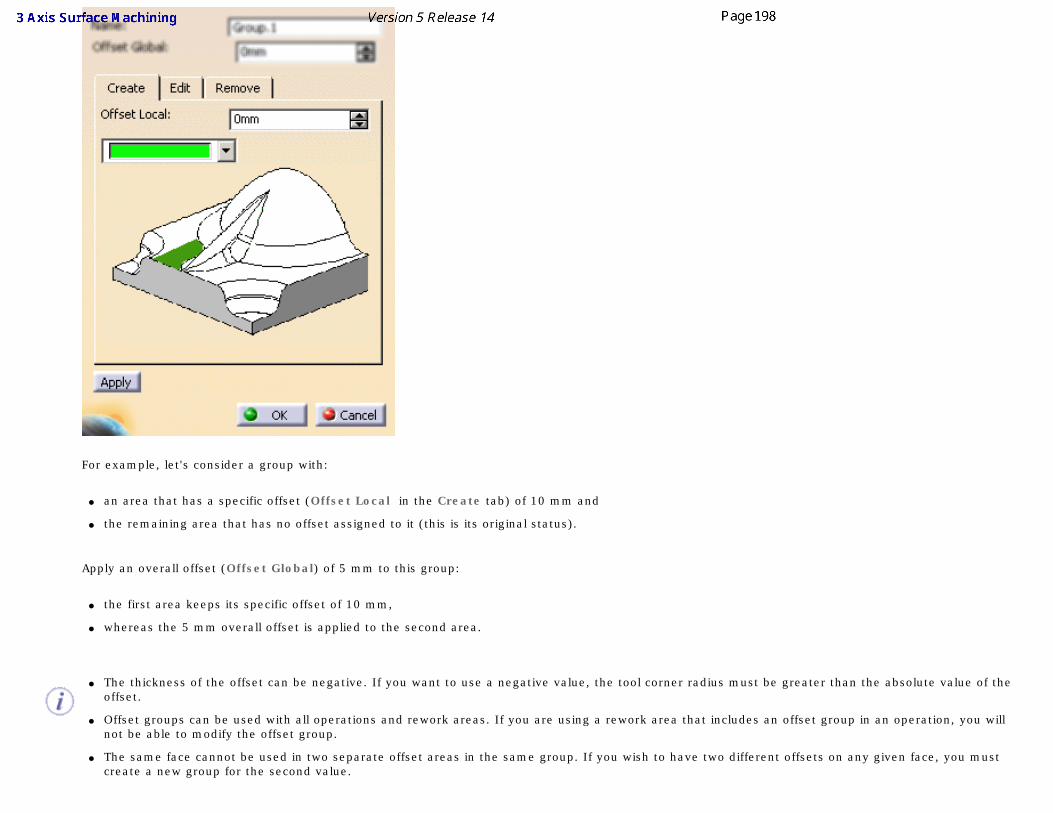
For example, let's consider a group with:
● an area that has a specific offset (Offset Local in the Create tab) of 10 mm and
● the remaining area that has no offset assigned to it (this is its original status).
Apply an overall offset (Offset Global) of 5 mm to this group:
● the first area keeps its specific offset of 10 mm,
● whereas the 5 mm overall offset is applied to the second area.
● The thickness of the offset can be negative. If you want to use a negative value, the tool corner radius must be greater than the absolute value of the
offset.
● Offset groups can be used with all operations and rework areas. If you are using a rework area that includes an offset group in an operation, you will not be able to modify the offset group.
● The same face cannot be used in two separate offset areas in the same group. If you wish to have two different offsets on any given face, you must create a new group for the second value.
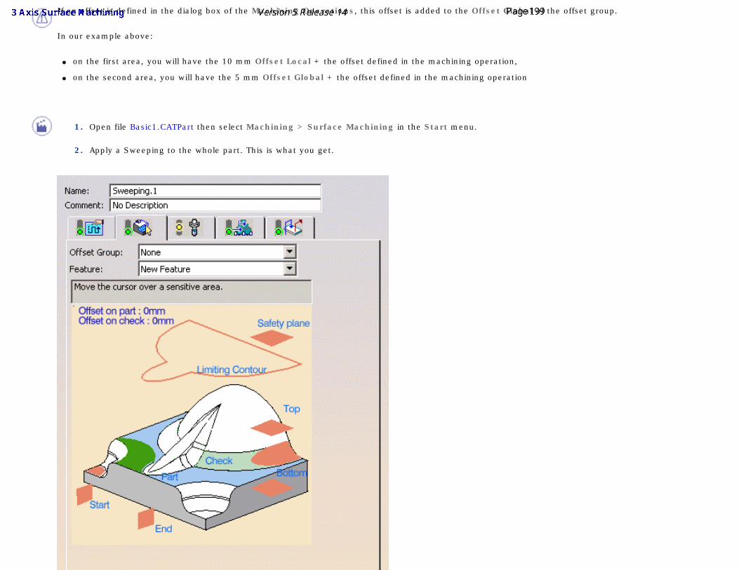
If an offset is defined in the dialog box of the Machining Operations, this offset is added to the Offset Global of the offset group.
In our example above:
● on the first area, you will have the 10 mm Offset Local + the offset defined in the machining operation,
● on the second area, you will have the 5 mm Offset Global + the offset defined in the machining operation
1. Open file Basic1.CATPart then select Machining > Surface Machining in the Start menu.
2. Apply a Sweeping to the whole part. This is what you get.
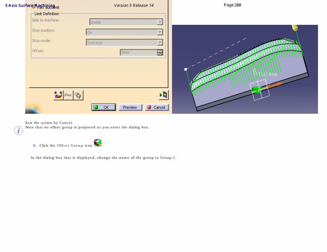
Exit the action by Cancel. Note that no offset group is proposed as you enter the dialog box.
3. Click the Offset Group icon .
In the dialog box that is displayed, change the name of the group to Group.1.
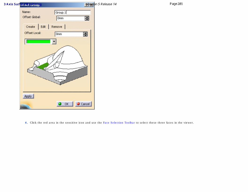
4. Click the red area in the sensitive icon and use the Face Selection Toolbar to select these three faces in the viewer.
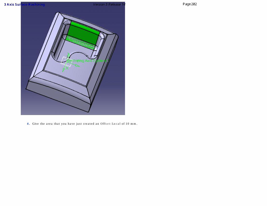
4. Give the area that you have just created an Offset Local of 10 mm.
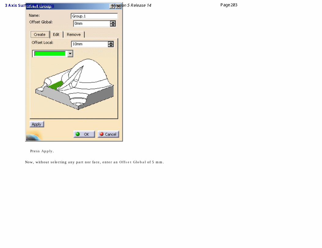
Press Apply.
Now, without selecting any part nor face, enter an Offset Global of 5 mm.
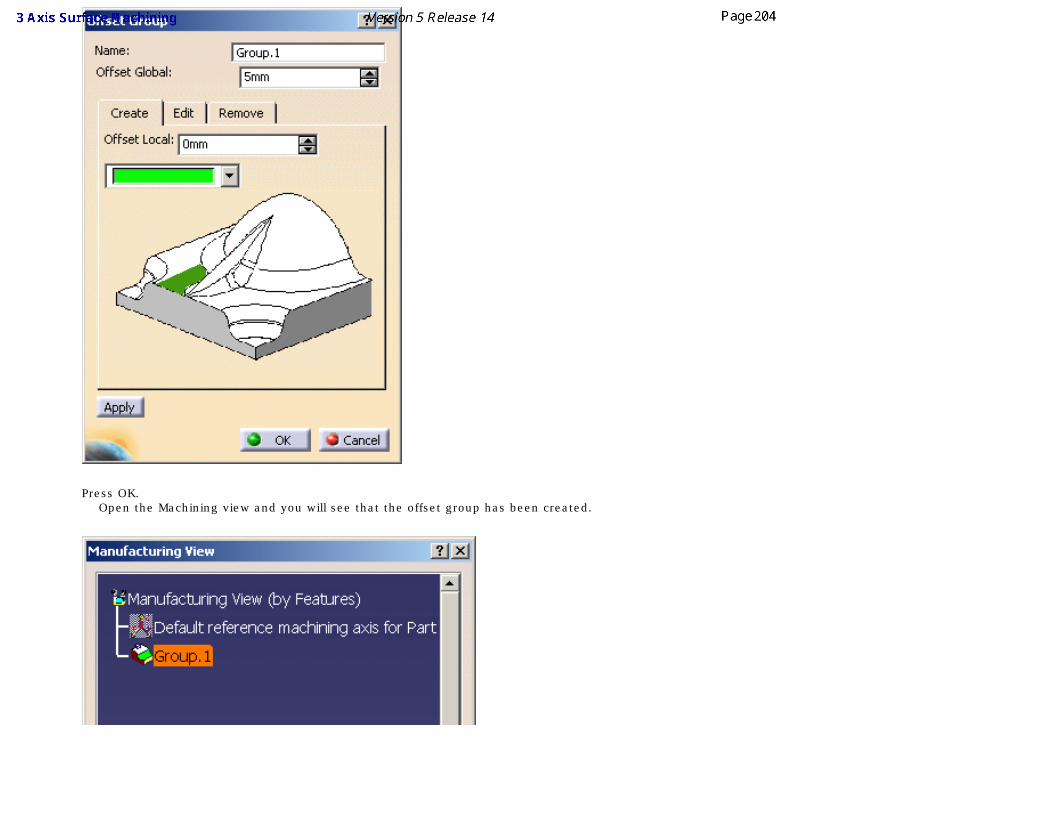
Press OK. Open the Machining view and you will see that the offset group has been created.
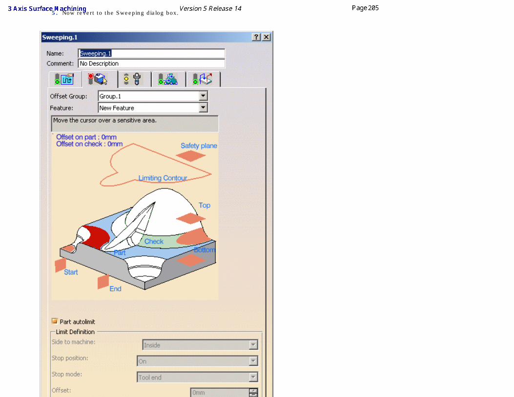
5. Now revert to the Sweeping dialog box.
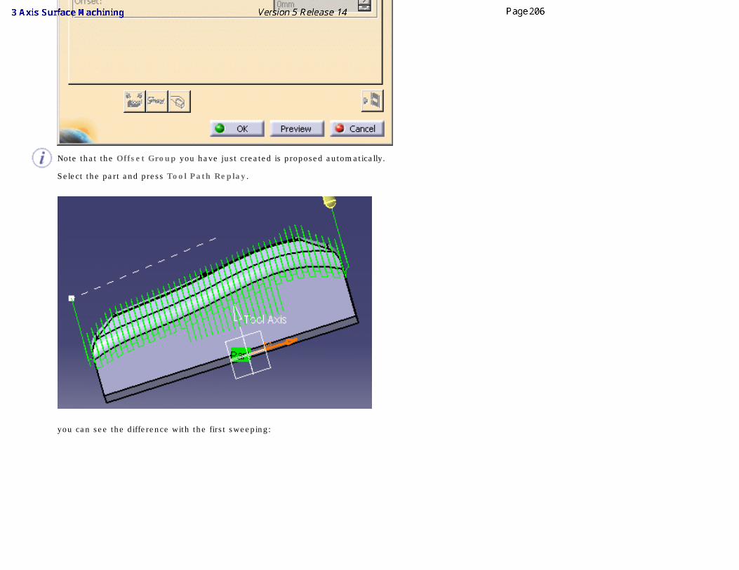
Note that the Offset Group you have just created is proposed automatically.
Select the part and press Tool Path Replay.
you can see the difference with the first sweeping:
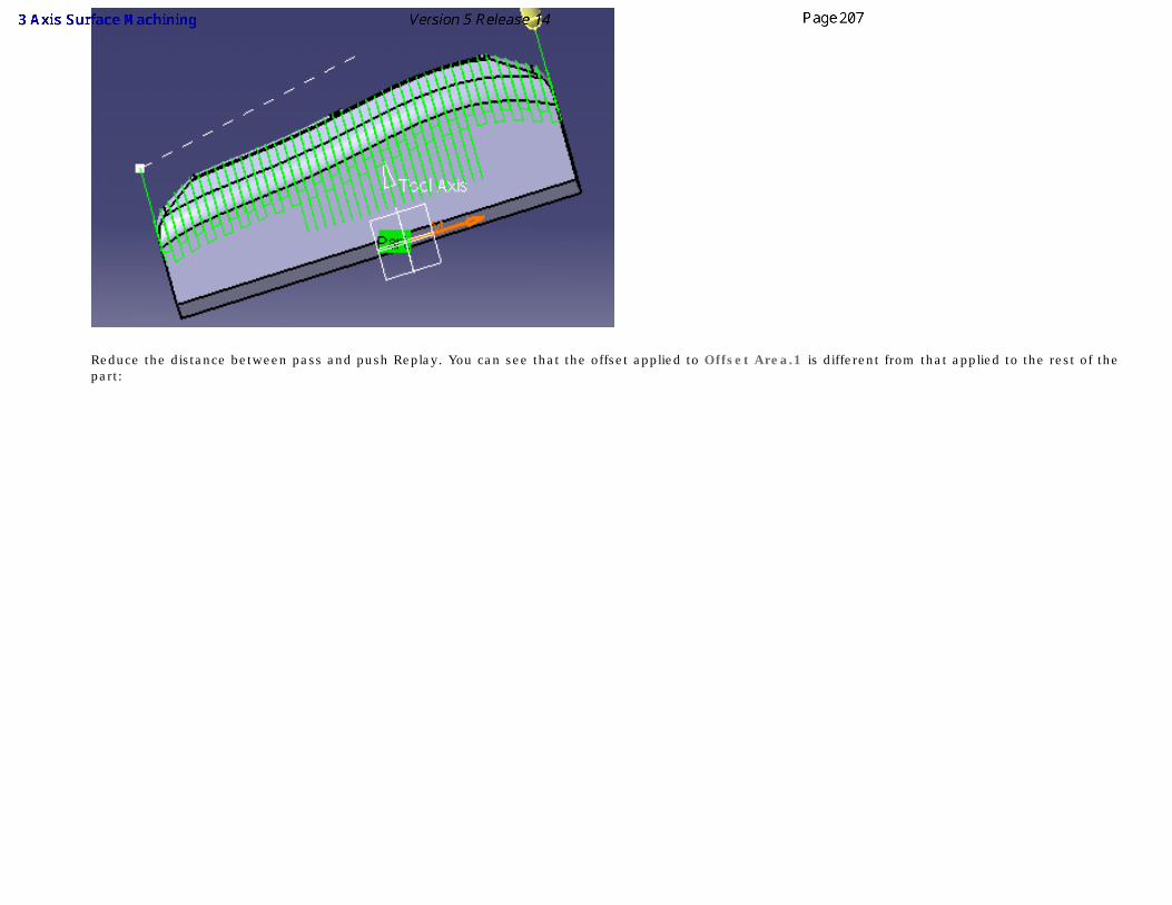
Reduce the distance between pass and push Replay. You can see that the offset applied to Offset Area.1 is different from that applied to the rest of the part:
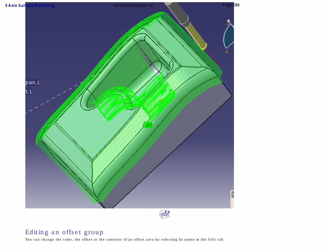
Editing an offset group
You can change the color, the offset or the contents of an offset area by selecting its name in the Edit tab.
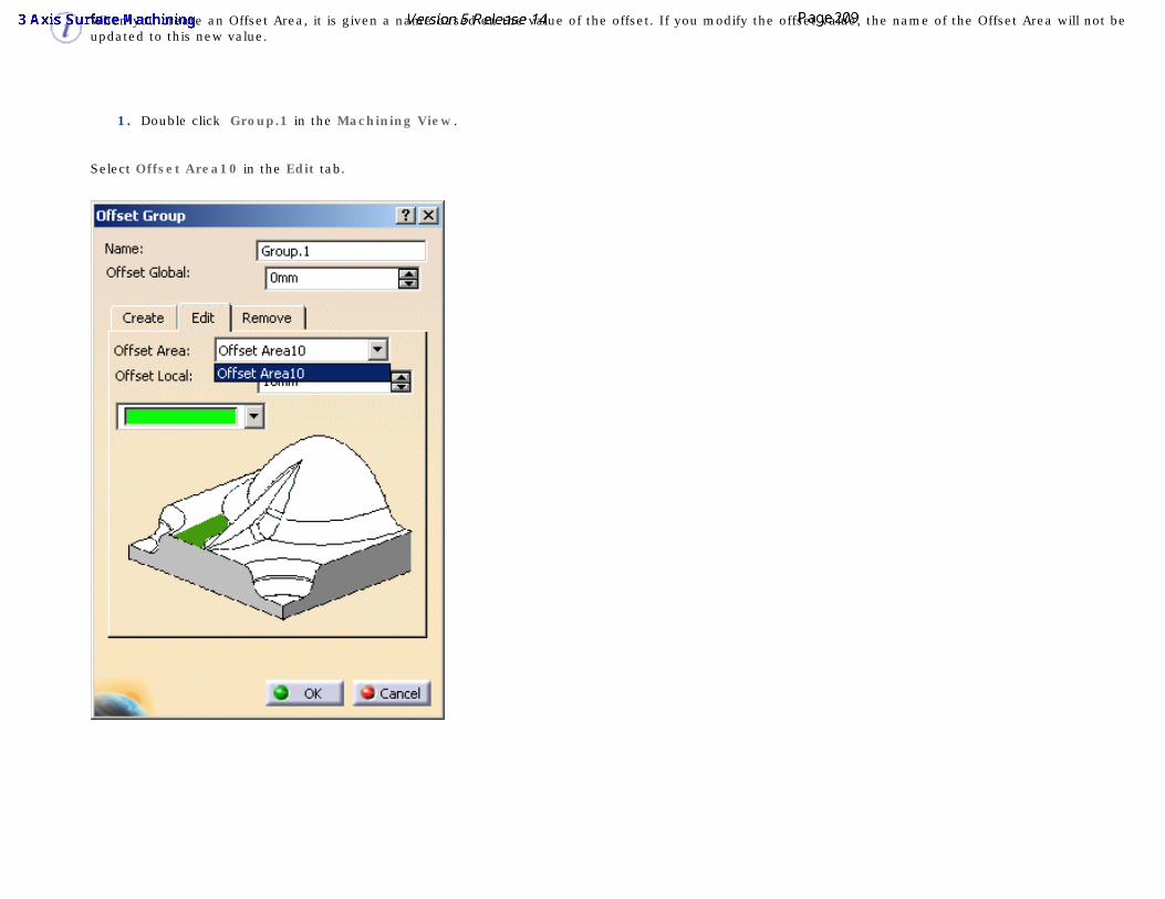
When you create an Offset Area, it is given a name based on the value of the offset. If you modify the offset value, the name of the Offset Area will not be updated to this new value.
1. Double click Group.1 in the Machining View.
Select Offset Area10 in the Edit tab.
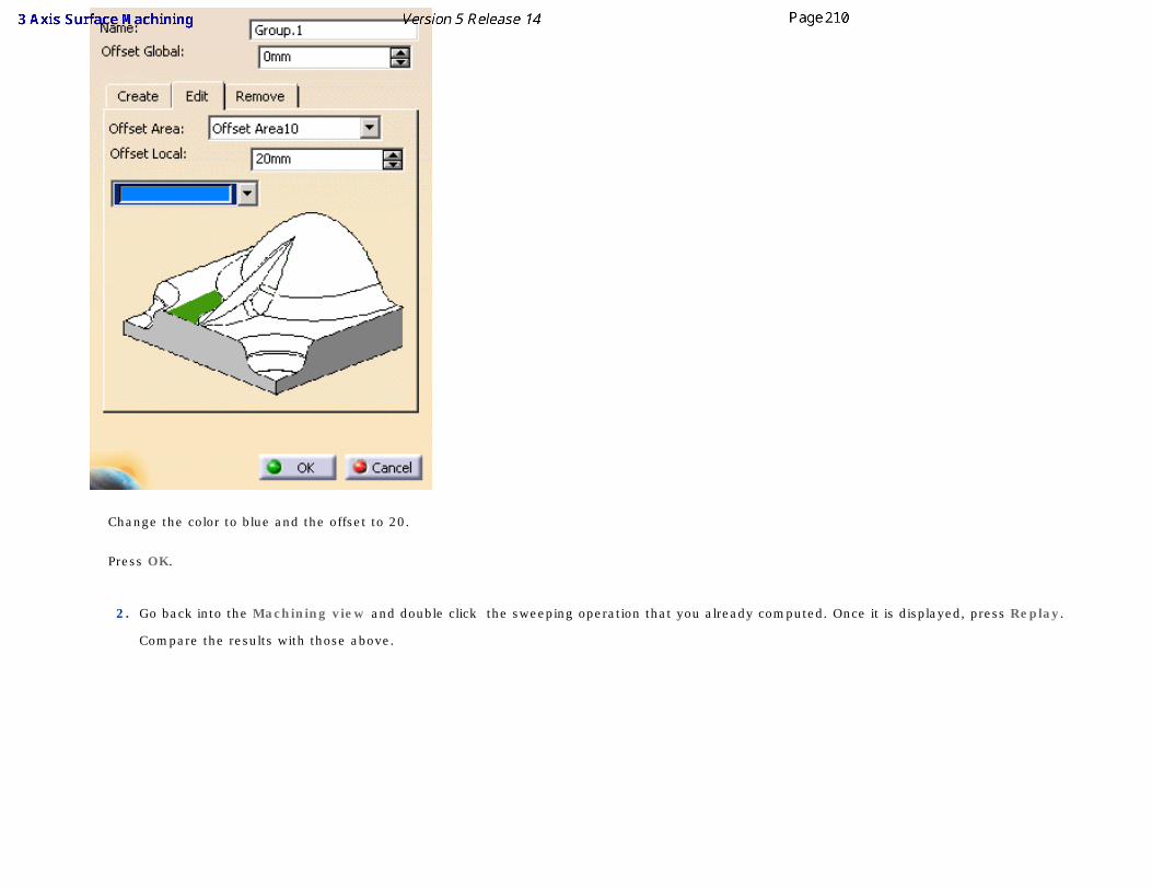
Change the color to blue and the offset to 20.
Press OK.
2. Go back into the Machining view and double click the sweeping operation that you already computed. Once it is displayed, press Replay.
Compare the results with those above.
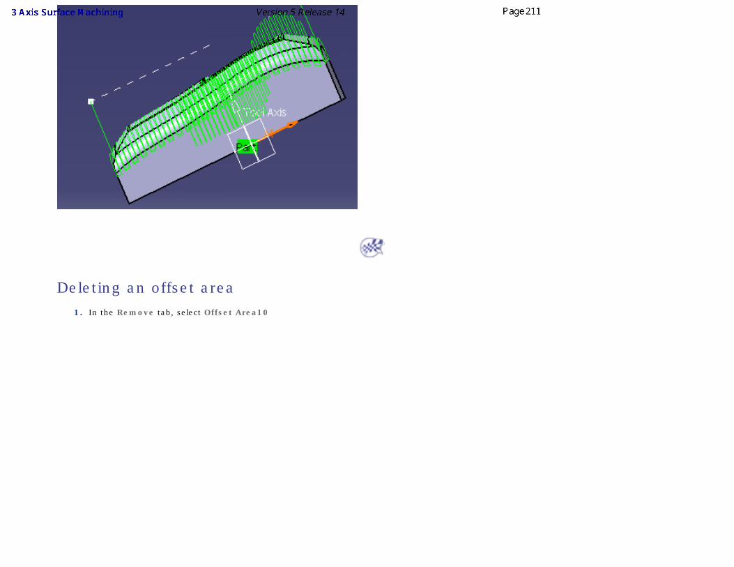
Deleting an offset area
1. In the Remove tab, select Offset Area10
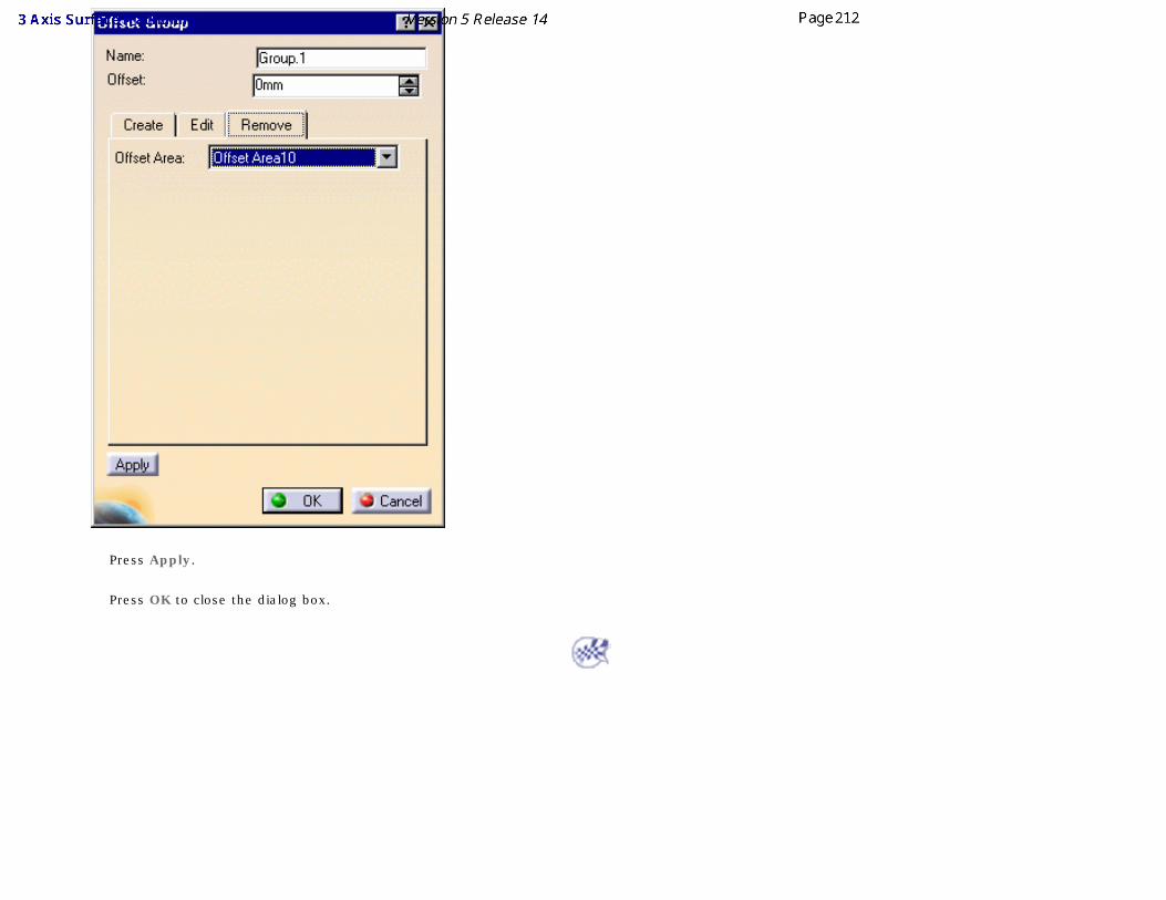
Press Apply.
Press OK to close the dialog box.
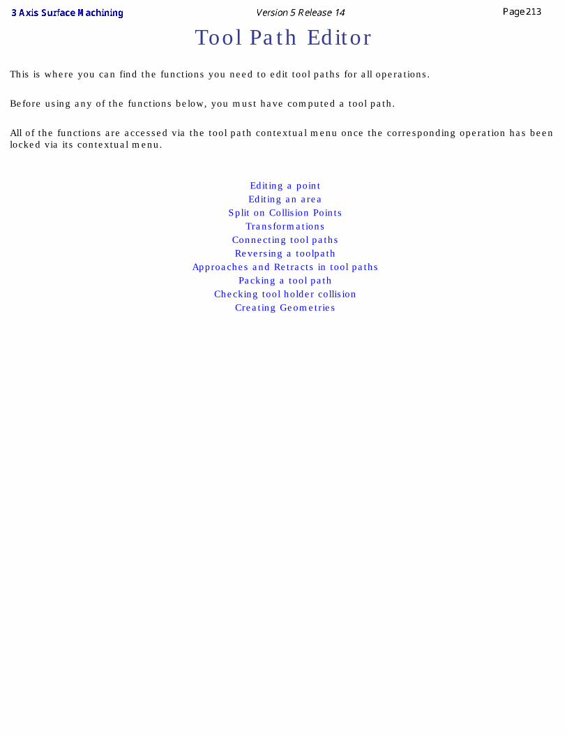
Tool Path Editor This is where you can find the functions you need to edit tool paths for all operations.
Before using any of the functions below, you must have computed a tool path.
All of the functions are accessed via the tool path contextual menu once the corresponding operation has been locked via its contextual menu.
Editing a pointEditing an area
Split on Collision PointsTransformations
Connecting tool pathsReversing a toolpath
Approaches and Retracts in tool pathsPacking a tool path
Checking tool holder collisionCreating Geometries
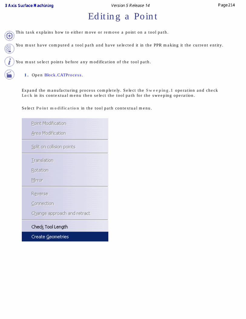
Editing a PointThis task explains how to either move or remove a point on a tool path.
You must have computed a tool path and have selected it in the PPR making it the current entity.
You must select points before any modification of the tool path.
1. Open Block.CATProcess.
Expand the manufacturing process completely. Select the Sweeping.1 operation and check Lock in its contextual menu then select the tool path for the sweeping operation.
Select Point modification in the tool path contextual menu.
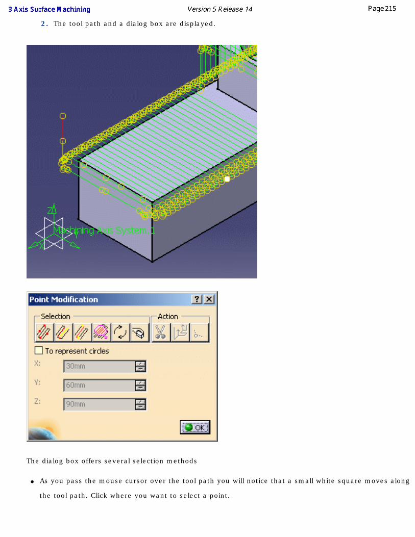
2. The tool path and a dialog box are displayed.
The dialog box offers several selection methods
● As you pass the mouse cursor over the tool path you will notice that a small white square moves along
the tool path. Click where you want to select a point.
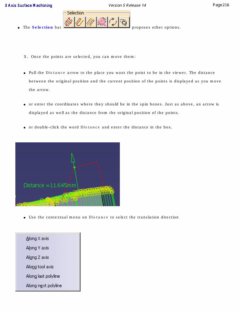
● The Selection bar proposes other options.
3. Once the points are selected, you can move them:
● Pull the Distance arrow to the place you want the point to be in the viewer. The distance
between the original position and the current position of the points is displayed as you move
the arrow.
● or enter the coordinates where they should be in the spin boxes. Just as above, an arrow is
displayed as well as the distance from the original position of the points.
● or double-click the word Distance and enter the distance in the box.
● Use the contextual menu on Distance to select the translation direction
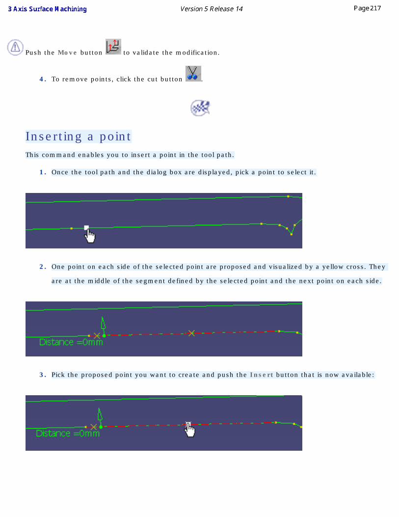
Push the Move button to validate the modification.
4. To remove points, click the cut button .
Inserting a point This command enables you to insert a point in the tool path.
1. Once the tool path and the dialog box are displayed, pick a point to select it.
2. One point on each side of the selected point are proposed and visualized by a yellow cross. They
are at the middle of the segment defined by the selected point and the next point on each side.
3. Pick the proposed point you want to create and push the Insert button that is now available:
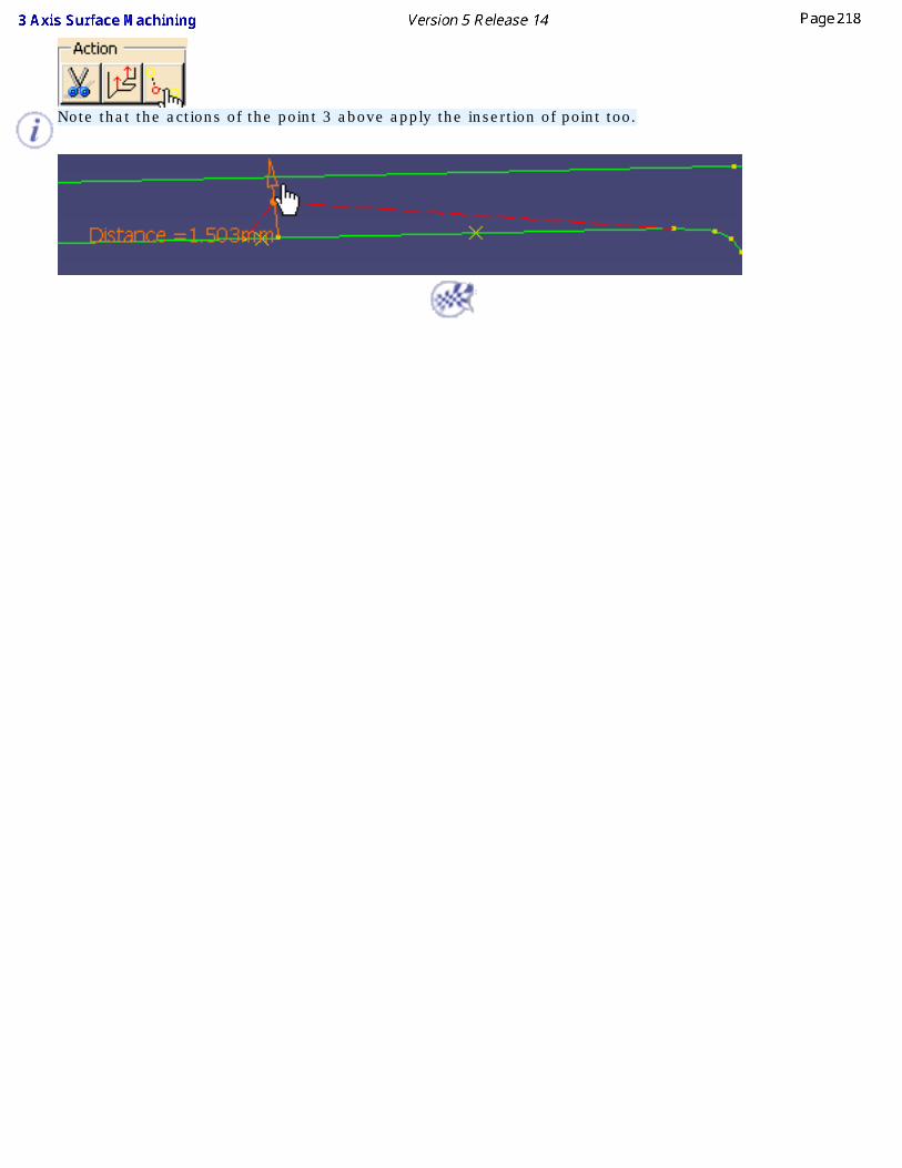
Note that the actions of the point 3 above apply the insertion of point too.
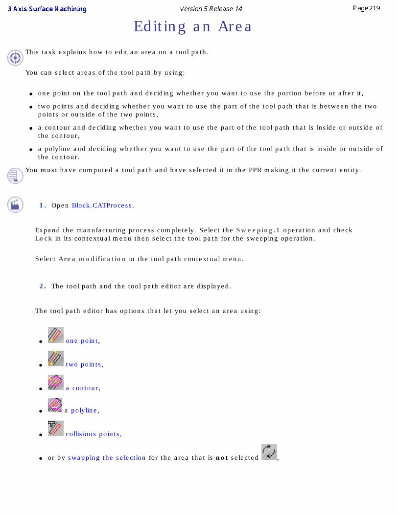
Editing an Area This task explains how to edit an area on a tool path.
You can select areas of the tool path by using:
● one point on the tool path and deciding whether you want to use the portion before or after it,
● two points and deciding whether you want to use the part of the tool path that is between the two points or outside of the two points,
● a contour and deciding whether you want to use the part of the tool path that is inside or outside of the contour,
● a polyline and deciding whether you want to use the part of the tool path that is inside or outside of the contour.
You must have computed a tool path and have selected it in the PPR making it the current entity.
1. Open Block.CATProcess.
Expand the manufacturing process completely. Select the Sweeping.1 operation and check Lock in its contextual menu then select the tool path for the sweeping operation.
Select Area modification in the tool path contextual menu.
2. The tool path and the tool path editor are displayed.
The tool path editor has options that let you select an area using:
● one point,
● two points,
● a contour,
● a polyline,
● collisions points,
● or by swapping the selection for the area that is not selected ,
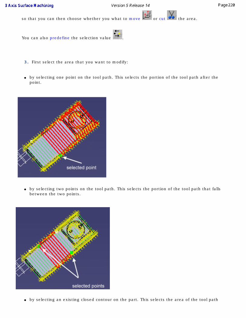
so that you can then choose whether you what to move or cut the area.
You can also predefine the selection value .
3. First select the area that you want to modify:
● by selecting one point on the tool path. This selects the portion of the tool path after the point.
● by selecting two points on the tool path. This selects the portion of the tool path that falls between the two points.
● by selecting an existing closed contour on the part. This selects the area of the tool path
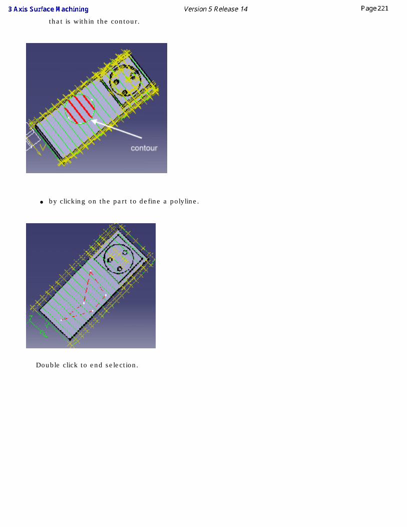
that is within the contour.
● by clicking on the part to define a polyline.
Double click to end selection.
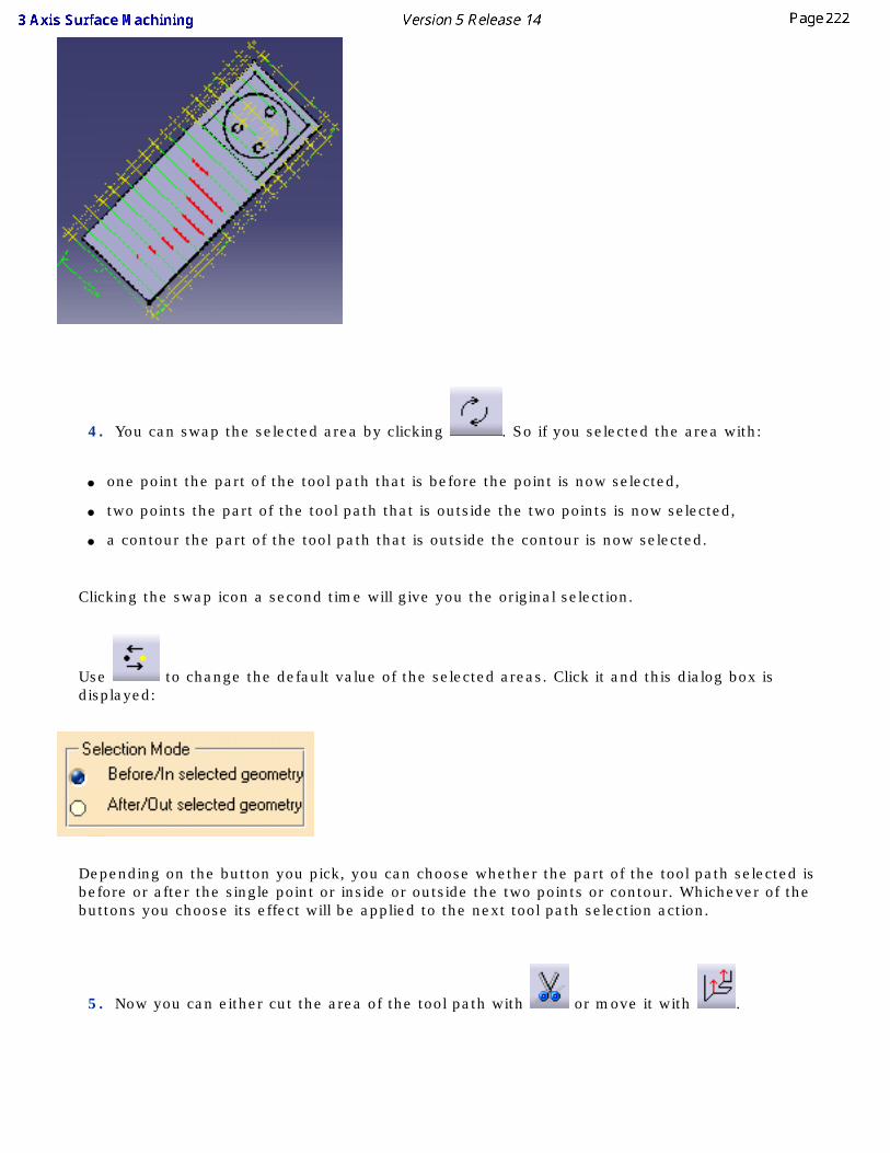
4. You can swap the selected area by clicking . So if you selected the area with:
● one point the part of the tool path that is before the point is now selected,
● two points the part of the tool path that is outside the two points is now selected,
● a contour the part of the tool path that is outside the contour is now selected.
Clicking the swap icon a second time will give you the original selection.
Use to change the default value of the selected areas. Click it and this dialog box is displayed:
Depending on the button you pick, you can choose whether the part of the tool path selected is before or after the single point or inside or outside the two points or contour. Whichever of the buttons you choose its effect will be applied to the next tool path selection action.
5. Now you can either cut the area of the tool path with or move it with .
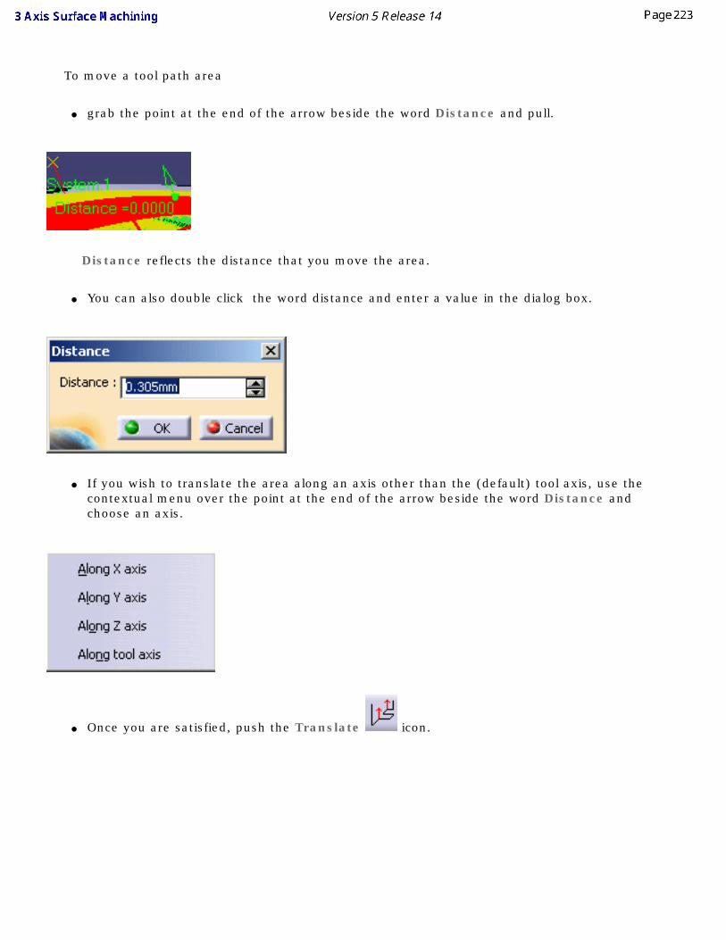
To move a tool path area
● grab the point at the end of the arrow beside the word Distance and pull.
Distance reflects the distance that you move the area.
● You can also double click the word distance and enter a value in the dialog box.
● If you wish to translate the area along an axis other than the (default) tool axis, use the contextual menu over the point at the end of the arrow beside the word Distance and choose an axis.
● Once you are satisfied, push the Translate icon.
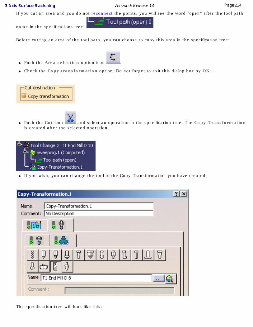
If you cut an area and you do not reconnect the points, you will see the word "open" after the tool path
name in the specifications tree.
Before cutting an area of the tool path, you can choose to copy this area in the specification tree:
● Push the Area selection option icon .
● Check the Copy transformation option. Do not forget to exit this dialog box by OK.
● Push the Cut icon and select an operation in the specification tree. The Copy-Transformation is created after the selected operation.
● If you wish, you can change the tool of the Copy-Transformation you have created:
The specification tree will look like this:
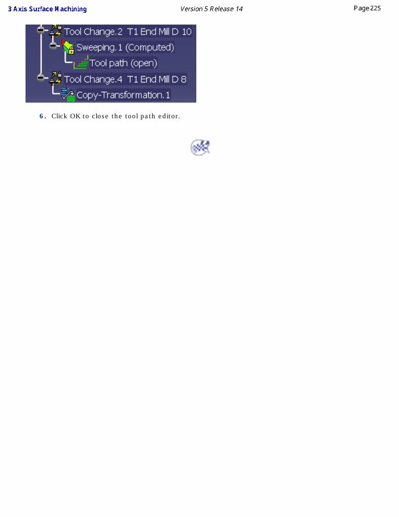
6. Click OK to close the tool path editor.
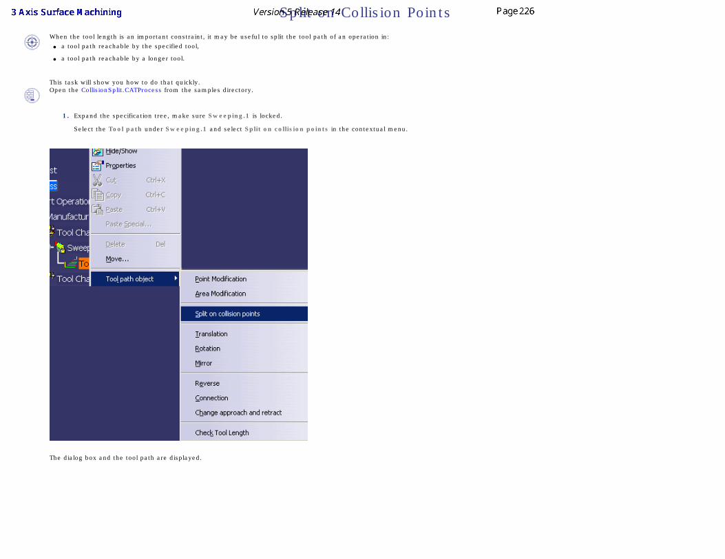
Split on Collision Points When the tool length is an important constraint, it may be useful to split the tool path of an operation in:
● a tool path reachable by the specified tool,
● a tool path reachable by a longer tool.
This task will show you how to do that quickly.Open the CollisionSplit.CATProcess from the samples directory.
1. Expand the specification tree, make sure Sweeping.1 is locked.
Select the Tool path under Sweeping.1 and select Split on collision points in the contextual menu.
The dialog box and the tool path are displayed.
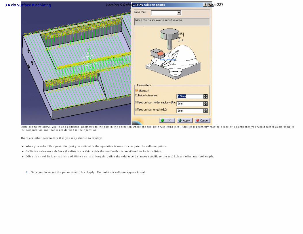
Extra geometry allows you to add additional geometry to the part in the operation where the tool path was computed. Additional geometry may be a face or a clamp that you would rather avoid using in the computation and that is not defined in the operation.
There are other parameters that you may choose to modify:
● When you select Use part, the part you defined in the operation is used to compute the collision points.
● Collision tolerance defines the distance within which the tool holder is considered to be in collision.
● Offset on tool holder radius and Offset on tool length define the tolerance distances specific to the tool holder radius and tool length.
2. Once you have set the parameters, click Apply. The points in collision appear in red:
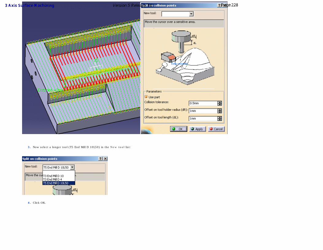
3. Now select a longer tool (T5 End Mill D 10L50) in the New tool list:
4. Click OK.
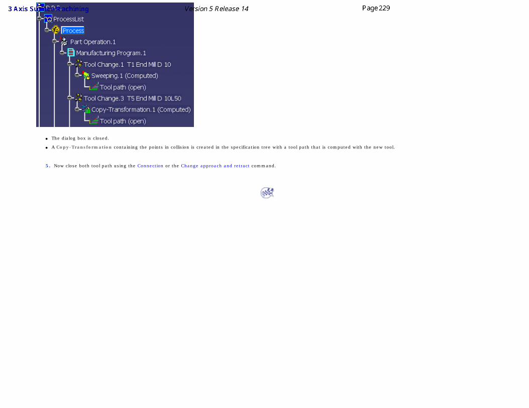
● The dialog box is closed.
● A Copy-Transformation containing the points in collision is created in the specification tree with a tool path that is computed with the new tool.
5. Now close both tool path using the Connection or the Change approach and retract command.
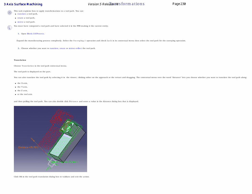
TransformationsThis task explains how to apply transformations to a tool path. You can:
● translate a tool path,
● rotate a tool path,
● mirror a tool path.
You must have computed a tool path and have selected it in the PPR making it the current entity.
1. Open Block.CATProcess.
Expand the manufacturing process completely. Select the Sweeping.1 operation and check Lock in its contextual menu then select the tool path for the sweeping operation.
2. Choose whether you want to translate, rotate or mirror-reflect the tool path.
3. Translation
Choose Translation in the tool path contextual menu.
The tool path is displayed on the part.
You can also translate the tool path by selecting it in the viewer, clicking either on the approach or the retract and dragging. The contextual menu over the word "distance" lets you choose whether you want to translate the tool path along:
● the X axis,
● the Y axis,
● the Z axis,
● or the tool axis.
and then pulling the tool path. You can also double click Distance and enter a value in the distance dialog box that is displayed.
Click OK in the tool path translation dialog box to validate and exit the action.
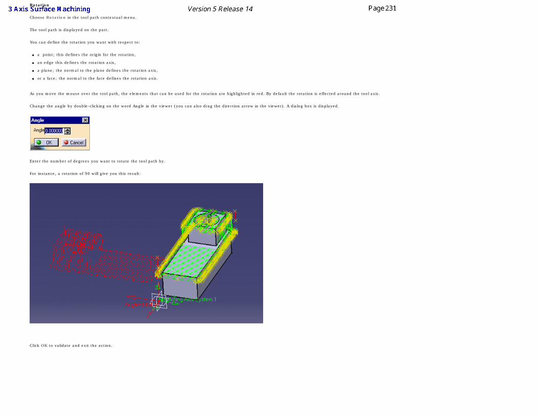
Rotation
Choose Rotation in the tool path contextual menu.
The tool path is displayed on the part.
You can define the rotation you want with respect to:
● a point; this defines the origin for the rotation,
● an edge this defines the rotation axis,
● a plane; the normal to the plane defines the rotation axis,
● or a face; the normal to the face defines the rotation axis.
As you move the mouse over the tool path, the elements that can be used for the rotation are highlighted in red. By default the rotation is effected around the tool axis.
Change the angle by double-clicking on the word Angle in the viewer (you can also drag the direction arrow in the viewer). A dialog box is displayed.
Enter the number of degrees you want to rotate the tool path by.
For instance, a rotation of 90 will give you this result:
Click OK to validate and exit the action.
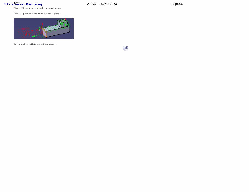
Mirror
Choose Mirror in the tool path contextual menu.
Choose a plane or a face to be the mirror plane.
Double click to validate and exit the action.
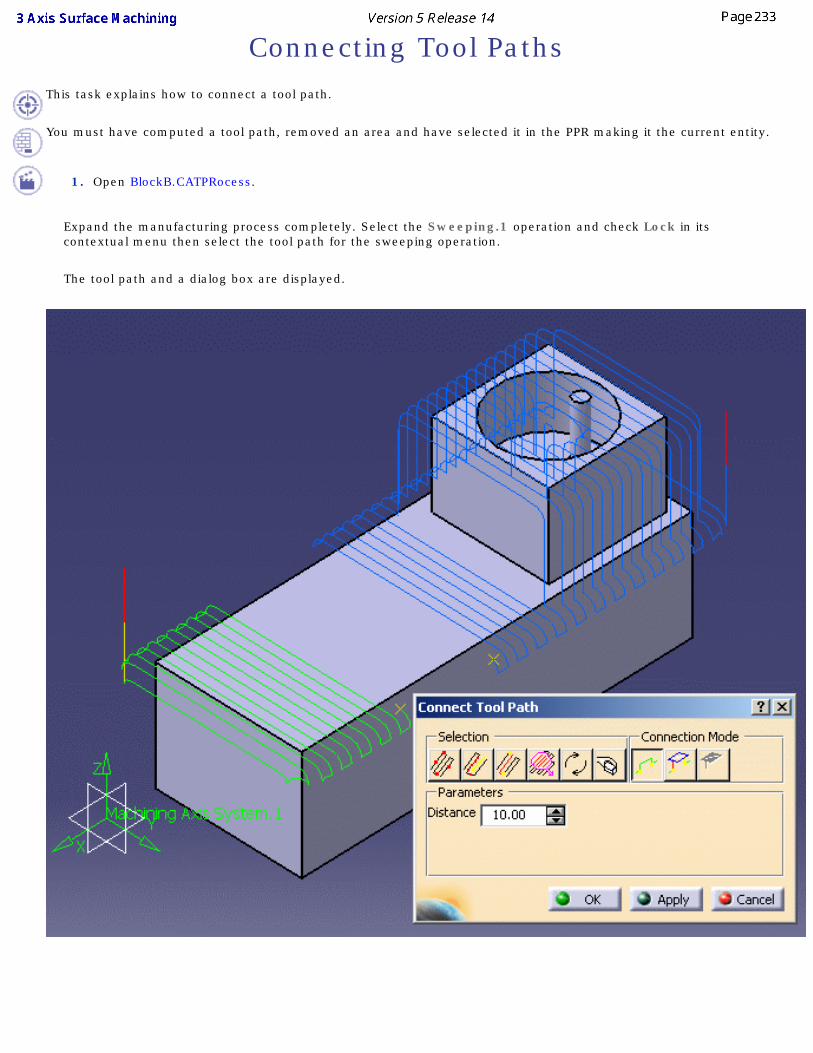
Connecting Tool PathsThis task explains how to connect a tool path.
You must have computed a tool path, removed an area and have selected it in the PPR making it the current entity.
1. Open BlockB.CATPRocess.
Expand the manufacturing process completely. Select the Sweeping.1 operation and check Lock in its contextual menu then select the tool path for the sweeping operation.
The tool path and a dialog box are displayed.
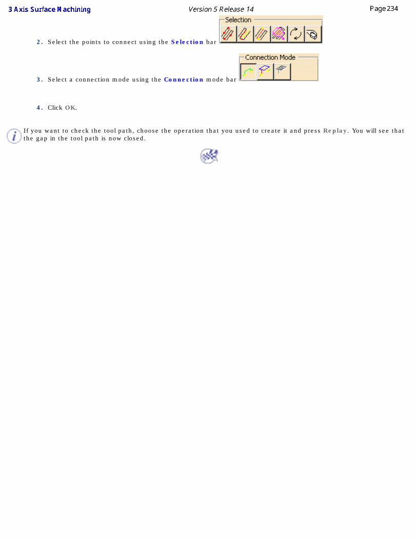
2. Select the points to connect using the Selection bar
3. Select a connection mode using the Connection mode bar
4. Click OK.
If you want to check the tool path, choose the operation that you used to create it and press Replay. You will see that the gap in the tool path is now closed.
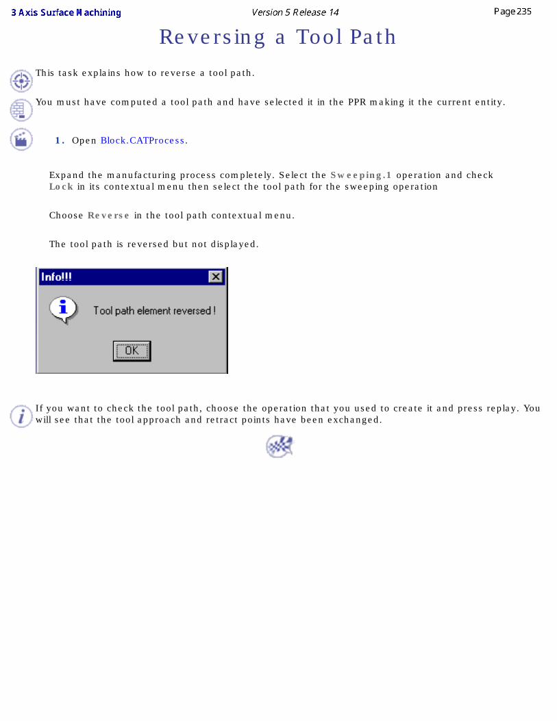
Reversing a Tool PathThis task explains how to reverse a tool path.
You must have computed a tool path and have selected it in the PPR making it the current entity.
1. Open Block.CATProcess.
Expand the manufacturing process completely. Select the Sweeping.1 operation and check Lock in its contextual menu then select the tool path for the sweeping operation
Choose Reverse in the tool path contextual menu.
The tool path is reversed but not displayed.
If you want to check the tool path, choose the operation that you used to create it and press replay. You will see that the tool approach and retract points have been exchanged.
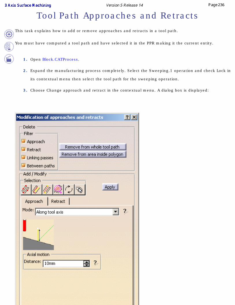
Tool Path Approaches and RetractsThis task explains how to add or remove approaches and retracts in a tool path.
You must have computed a tool path and have selected it in the PPR making it the current entity.
1. Open Block.CATProcess.
2. Expand the manufacturing process completely. Select the Sweeping.1 operation and check Lock in
its contextual menu then select the tool path for the sweeping operation.
3. Choose Change approach and retract in the contextual menu. A dialog box is displayed:
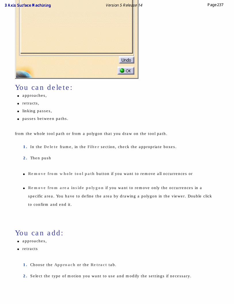
You can delete:● approaches,
● retracts,
● linking passes,
● passes between paths.
from the whole tool path or from a polygon that you draw on the tool path.
1. In the Delete frame, in the Filter section, check the appropriate boxes.
2. Then push
● Remove from whole tool path button if you want to remove all occurrences or
● Remove from area inside polygon if you want to remove only the occurrences in a
specific area. You have to define the area by drawing a polygon in the viewer. Double click
to confirm and end it.
You can add:● approaches,
● retracts
1. Choose the Approach or the Retract tab.
2. Select the type of motion you want to use and modify the settings if necessary.
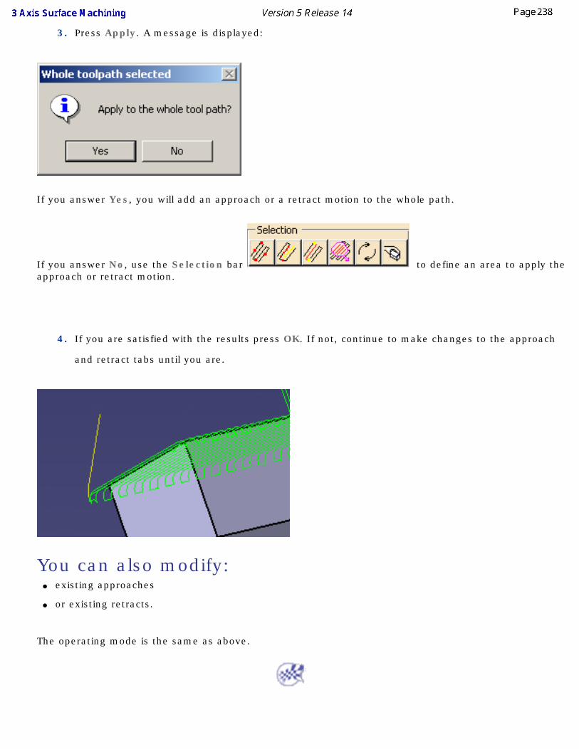
3. Press Apply. A message is displayed:
If you answer Yes, you will add an approach or a retract motion to the whole path.
If you answer No, use the Selection bar to define an area to apply the approach or retract motion.
4. If you are satisfied with the results press OK. If not, continue to make changes to the approach
and retract tabs until you are.
You can also modify:● existing approaches
● or existing retracts.
The operating mode is the same as above.
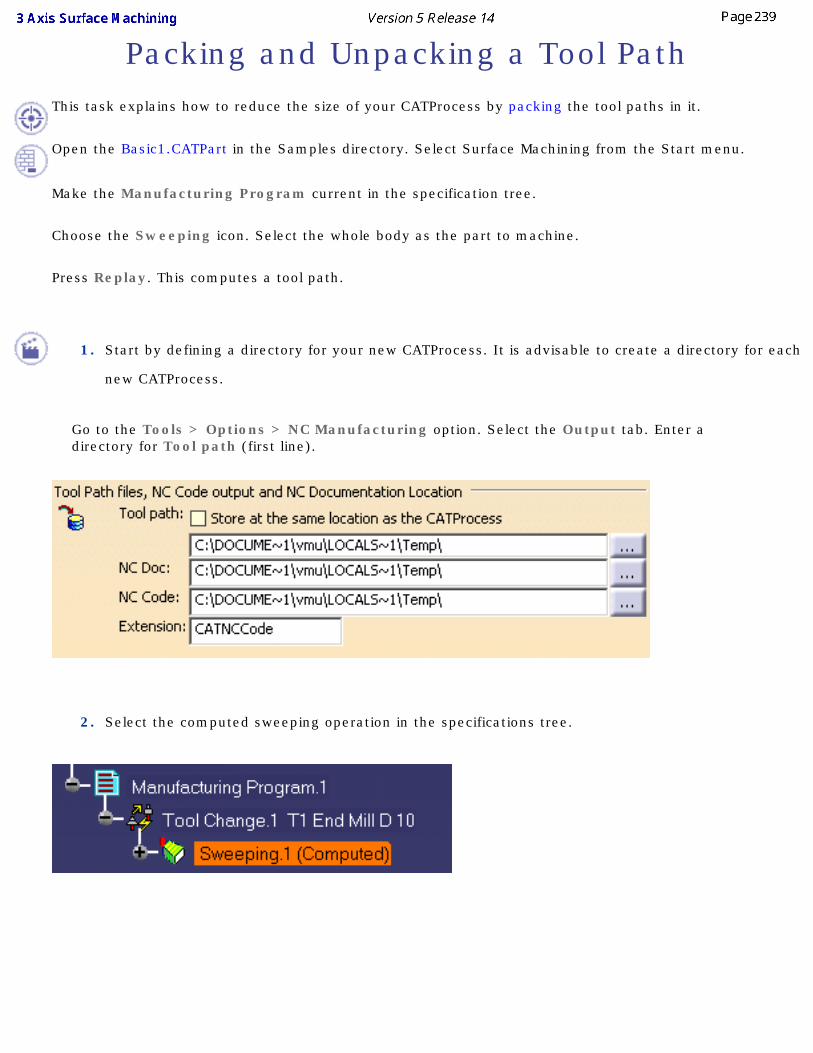
Packing and Unpacking a Tool PathThis task explains how to reduce the size of your CATProcess by packing the tool paths in it.
Open the Basic1.CATPart in the Samples directory. Select Surface Machining from the Start menu.
Make the Manufacturing Program current in the specification tree.
Choose the Sweeping icon. Select the whole body as the part to machine.
Press Replay. This computes a tool path.
1. Start by defining a directory for your new CATProcess. It is advisable to create a directory for each
new CATProcess.
Go to the Tools > Options > NC Manufacturing option. Select the Output tab. Enter a directory for Tool path (first line).
2. Select the computed sweeping operation in the specifications tree.
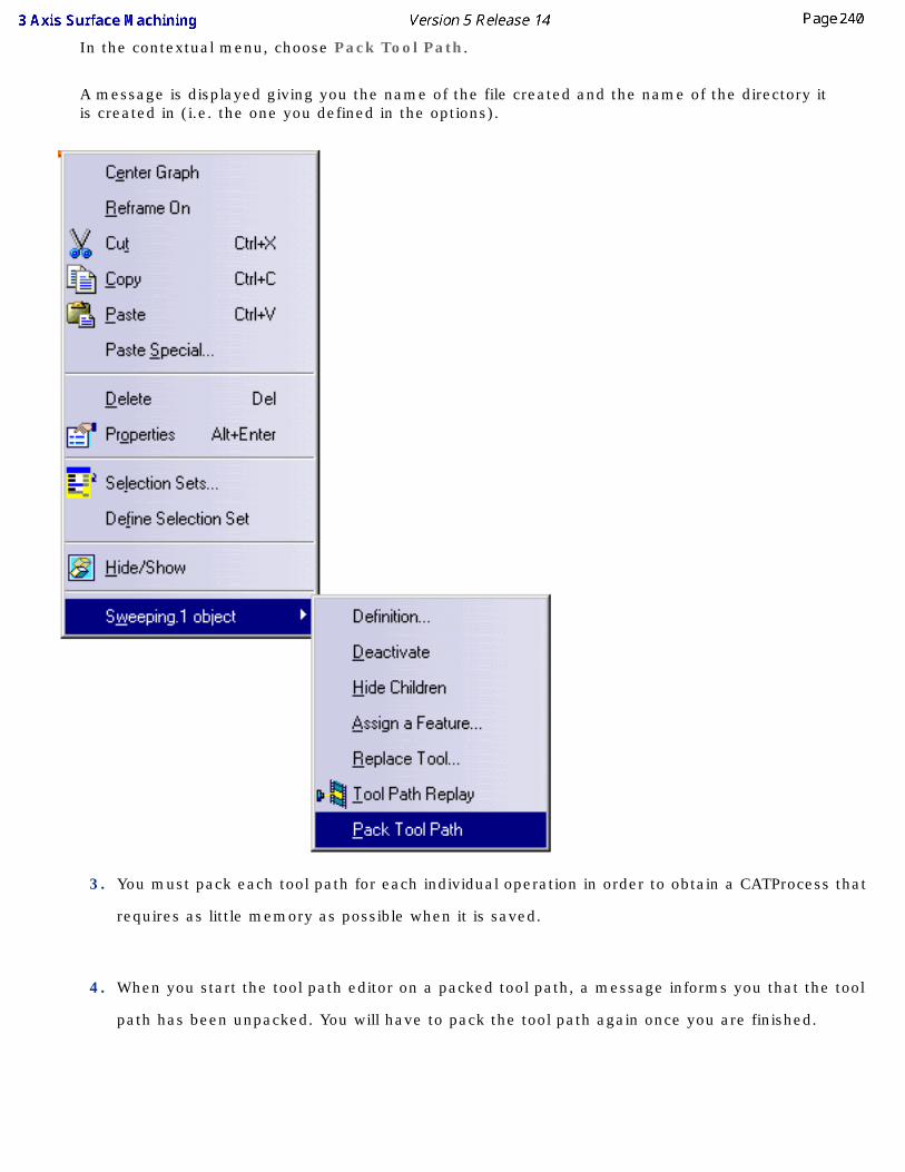
In the contextual menu, choose Pack Tool Path.
A message is displayed giving you the name of the file created and the name of the directory it is created in (i.e. the one you defined in the options).
3. You must pack each tool path for each individual operation in order to obtain a CATProcess that
requires as little memory as possible when it is saved.
4. When you start the tool path editor on a packed tool path, a message informs you that the tool
path has been unpacked. You will have to pack the tool path again once you are finished.

When you have a CATProcess that contains a packed tool path and you copy the CATProcess anywhere else, the file containing the tool path does not follow and the tool path cannot be replayed on the new computer. Solve this by sending the CATProcess to the new computer via the using the File > Send to option rather than copying it.
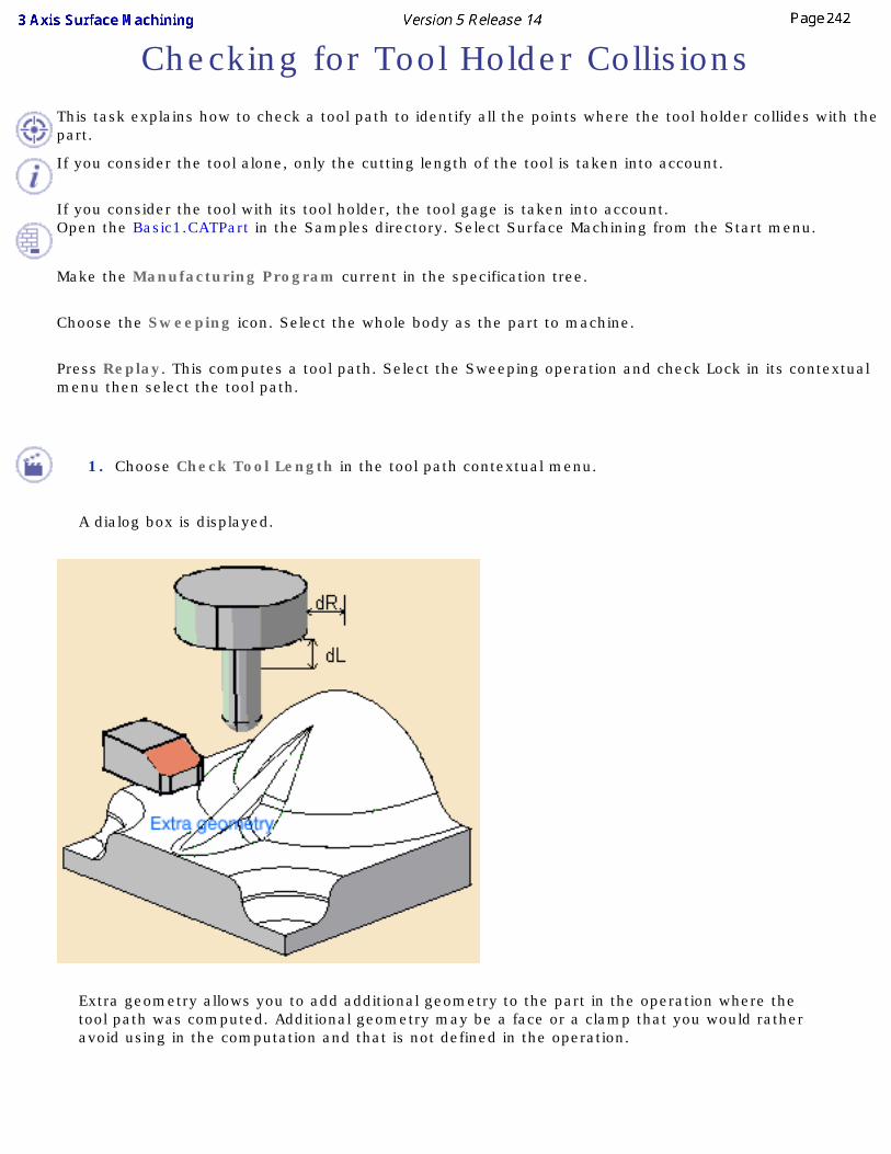
Checking for Tool Holder CollisionsThis task explains how to check a tool path to identify all the points where the tool holder collides with the part.
If you consider the tool alone, only the cutting length of the tool is taken into account.
If you consider the tool with its tool holder, the tool gage is taken into account.Open the Basic1.CATPart in the Samples directory. Select Surface Machining from the Start menu.
Make the Manufacturing Program current in the specification tree.
Choose the Sweeping icon. Select the whole body as the part to machine.
Press Replay. This computes a tool path. Select the Sweeping operation and check Lock in its contextual menu then select the tool path.
1. Choose Check Tool Length in the tool path contextual menu.
A dialog box is displayed.
Extra geometry allows you to add additional geometry to the part in the operation where the tool path was computed. Additional geometry may be a face or a clamp that you would rather avoid using in the computation and that is not defined in the operation.
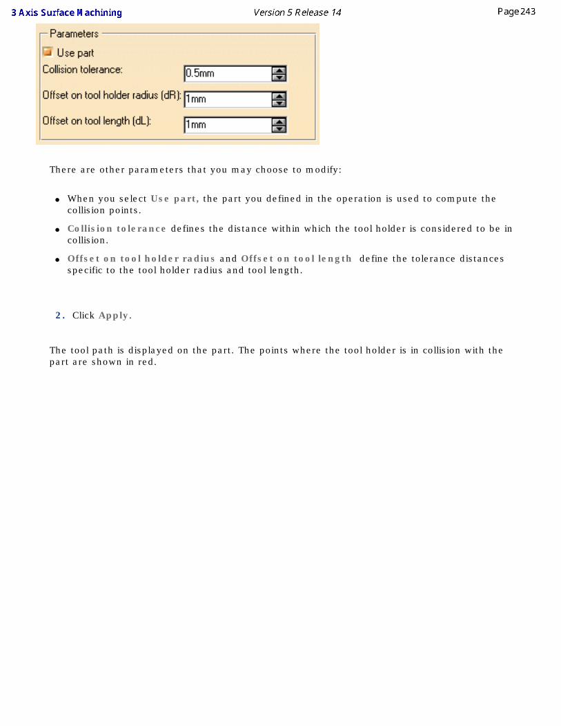
There are other parameters that you may choose to modify:
● When you select Use part, the part you defined in the operation is used to compute the collision points.
● Collision tolerance defines the distance within which the tool holder is considered to be in collision.
● Offset on tool holder radius and Offset on tool length define the tolerance distances specific to the tool holder radius and tool length.
2. Click Apply.
The tool path is displayed on the part. The points where the tool holder is in collision with the part are shown in red.
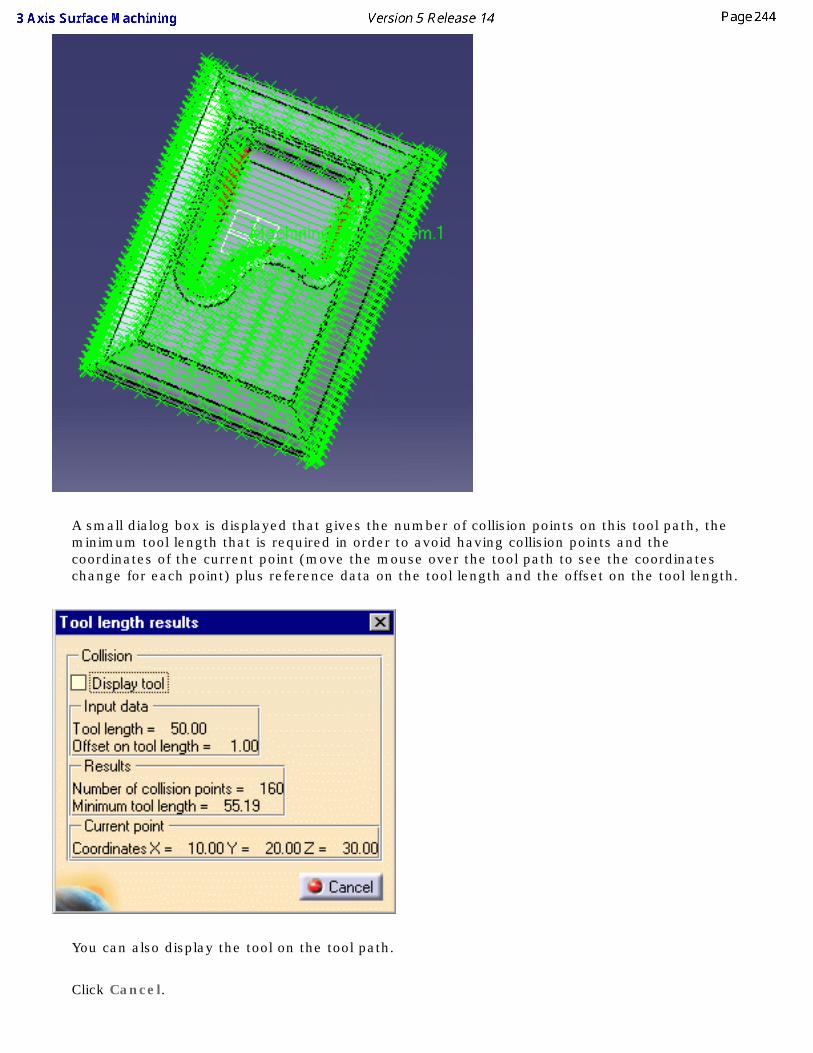
A small dialog box is displayed that gives the number of collision points on this tool path, the minimum tool length that is required in order to avoid having collision points and the coordinates of the current point (move the mouse over the tool path to see the coordinates change for each point) plus reference data on the tool length and the offset on the tool length.
You can also display the tool on the tool path.
Click Cancel.
Close the dialog box
This is only a visual check to let you see where the collision points are and find the tool length that is required to avoid them.
3. You now have the choice of either changing the tool length or editing the tool path in order to get
rid of the collision points.
If you want to change the tool length you must create a new tool or select another tool.
4. Select the tool path again in the specifications tree. Choose Area modification in the contextual
menu.
The tool path is displayed.
5. Click the Select collision points icon .
The same dialog box as above is displayed. Change the parameter values if you wish.
6. Press Apply to display the collision points in red on the toolpath.
You can then cut ( ) the collision points from the tool path.
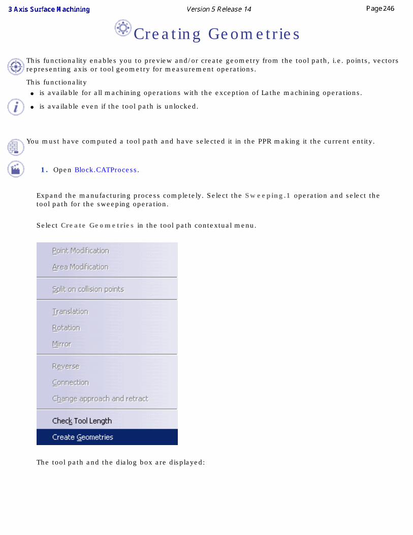
Creating GeometriesThis functionality enables you to preview and/or create geometry from the tool path, i.e. points, vectors representing axis or tool geometry for measurement operations.
This functionality ● is available for all machining operations with the exception of Lathe machining operations.
● is available even if the tool path is unlocked.
You must have computed a tool path and have selected it in the PPR making it the current entity.
1. Open Block.CATProcess.
Expand the manufacturing process completely. Select the Sweeping.1 operation and select the tool path for the sweeping operation.
Select Create Geometries in the tool path contextual menu.
The tool path and the dialog box are displayed:
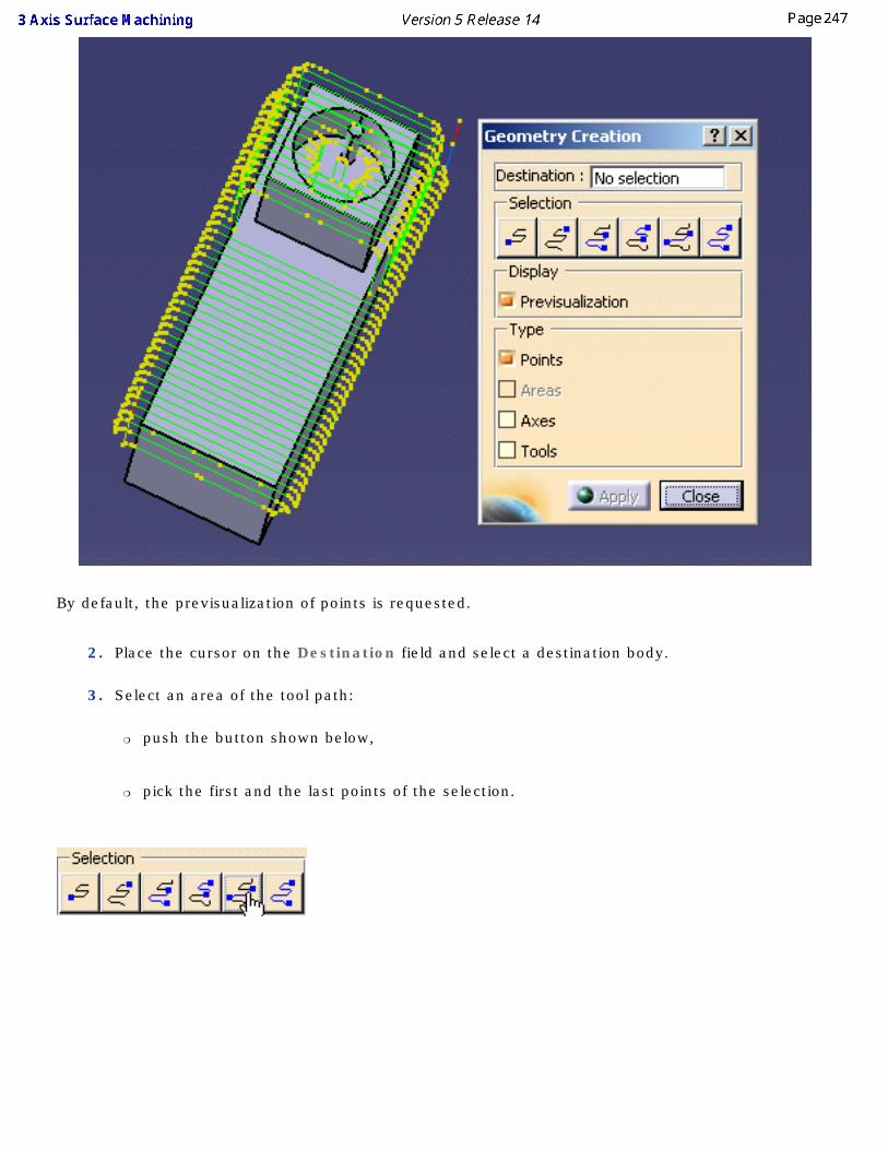
By default, the previsualization of points is requested.
2. Place the cursor on the Destination field and select a destination body.
3. Select an area of the tool path:
❍ push the button shown below,
❍ pick the first and the last points of the selection.
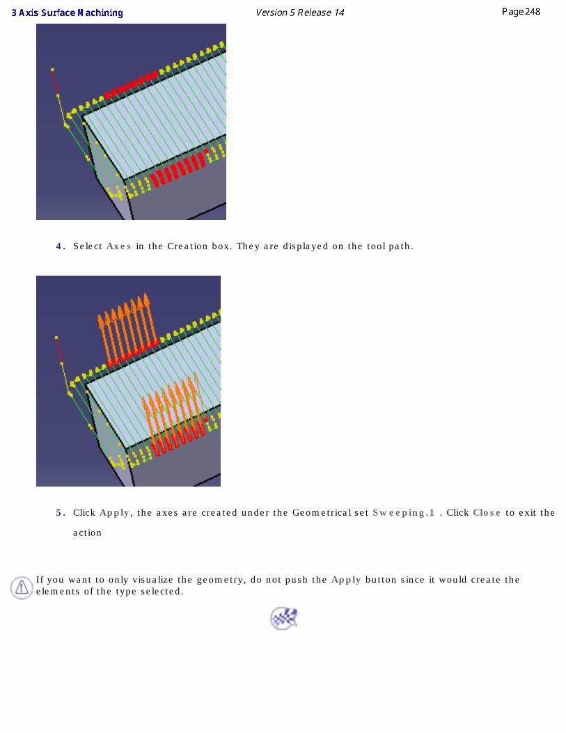
4. Select Axes in the Creation box. They are displayed on the tool path.
5. Click Apply, the axes are created under the Geometrical set Sweeping.1 . Click Close to exit the
action
If you want to only visualize the geometry, do not push the Apply button since it would create the elements of the type selected.

Importing files There are two types of files that can be imported into the Surface Machining workbench:
STL FilesImporting Files
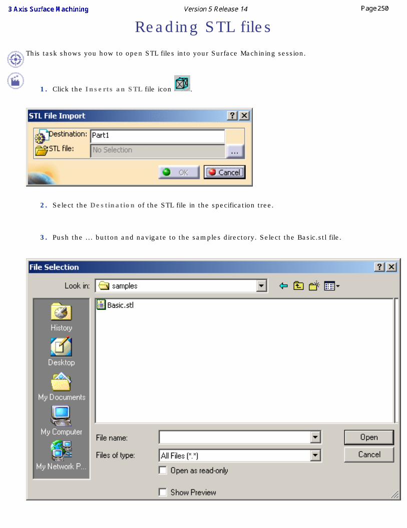
Reading STL filesThis task shows you how to open STL files into your Surface Machining session.
1. Click the Inserts an STL file icon .
2. Select the Destination of the STL file in the specification tree.
3. Push the ... button and navigate to the samples directory. Select the Basic.stl file.
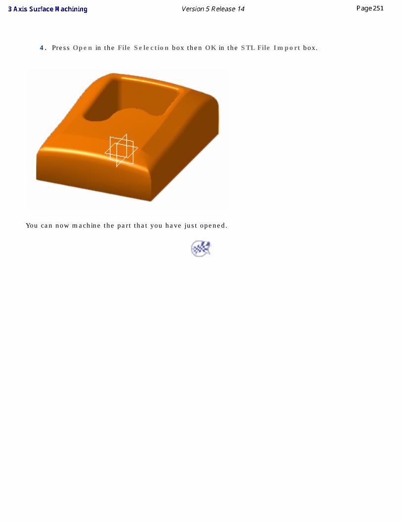
4. Press Open in the File Selection box then OK in the STL File Import box.
You can now machine the part that you have just opened.
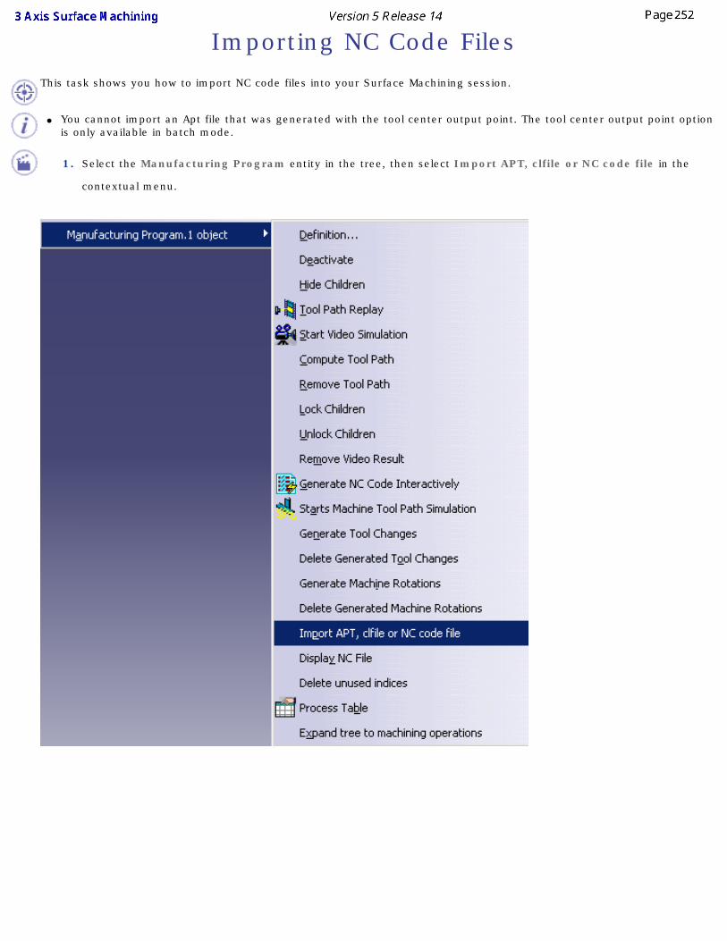
Importing NC Code FilesThis task shows you how to import NC code files into your Surface Machining session.
● You cannot import an Apt file that was generated with the tool center output point. The tool center output point option is only available in batch mode.
1. Select the Manufacturing Program entity in the tree, then select Import APT, clfile or NC code file in the
contextual menu.
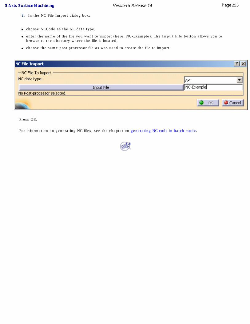
2. In the NC File Import dialog box:
● choose NCCode as the NC data type,
● enter the name of the file you want to import (here, NC-Example). The Input File button allows you to browse to the directory where the file is located,
● choose the same post processor file as was used to create the file to import.
Press OK.
For information on generating NC files, see the chapter on generating NC code in batch mode.
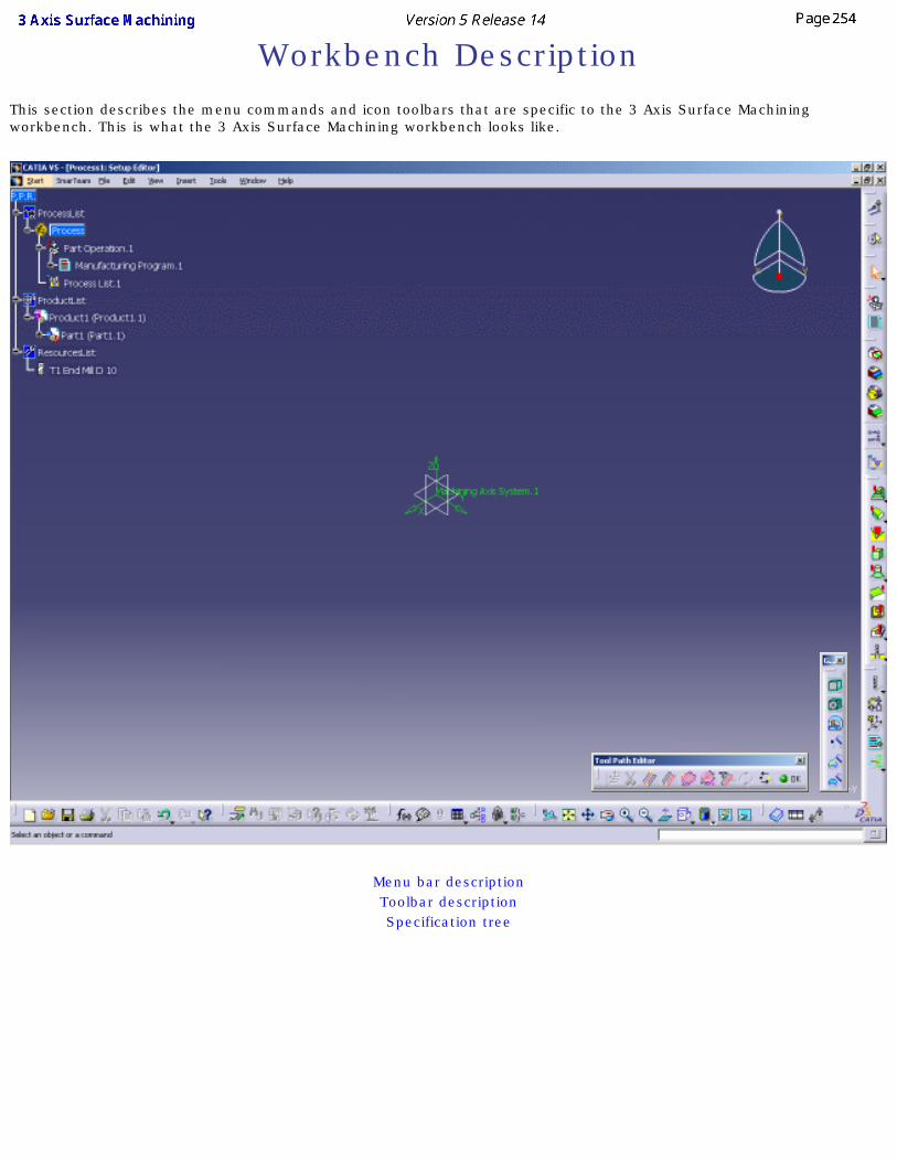
Workbench DescriptionThis section describes the menu commands and icon toolbars that are specific to the 3 Axis Surface Machining workbench. This is what the 3 Axis Surface Machining workbench looks like.
Menu bar descriptionToolbar descriptionSpecification tree
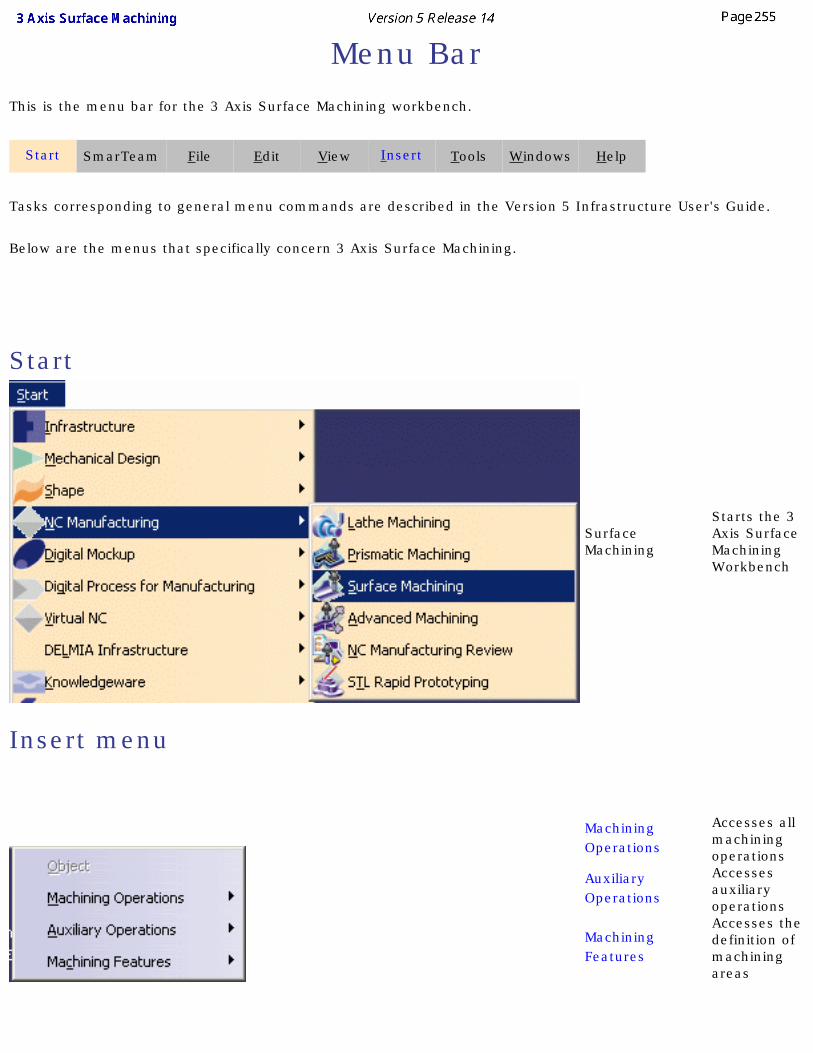
Menu BarThis is the menu bar for the 3 Axis Surface Machining workbench.
Start SmarTeam File Edit View Insert Tools Windows Help
Tasks corresponding to general menu commands are described in the Version 5 Infrastructure User's Guide.
Below are the menus that specifically concern 3 Axis Surface Machining.
Start
Surface Machining
Starts the 3 Axis Surface Machining Workbench
Insert menu
Machining Operations
Accesses all machining operations
Auxiliary Operations
Accesses auxiliary operations
Machining Features
Accesses the definition of machining areas
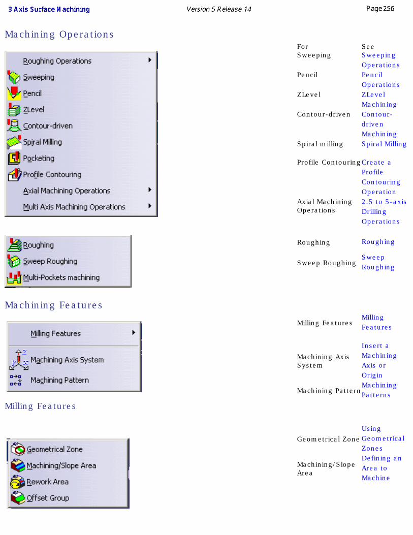
Machining Operations
For See Sweeping Sweeping
Operations Pencil Pencil
Operations ZLevel ZLevel
Machining Contour-driven Contour-
driven Machining
Spiral milling Spiral Milling Profile ContouringCreate a
Profile Contouring Operation
Axial Machining Operations
2.5 to 5-axis Drilling Operations
Roughing Roughing
Sweep RoughingSweep Roughing
Machining Features
Milling FeaturesMilling Features
Machining Axis System
Insert a Machining Axis or Origin
Machining PatternMachining Patterns
Milling Features
Geometrical ZoneUsing Geometrical Zones
Machining/Slope Area
Defining an Area to Machine

Rework Area Defining an Area to Rework
Offset Group Offset Group
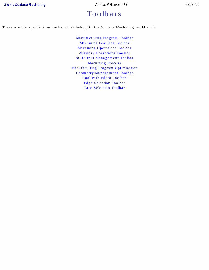
ToolbarsThese are the specific icon toolbars that belong to the Surface Machining workbench.
Manufacturing Program ToolbarMachining Features Toolbar
Machining Operations ToolbarAuxiliary Operations Toolbar
NC Output Management ToolbarMachining Process
Manufacturing Program Optimization Geometry Management Toolbar
Tool Path Editor ToolbarEdge Selection ToolbarFace Selection Toolbar
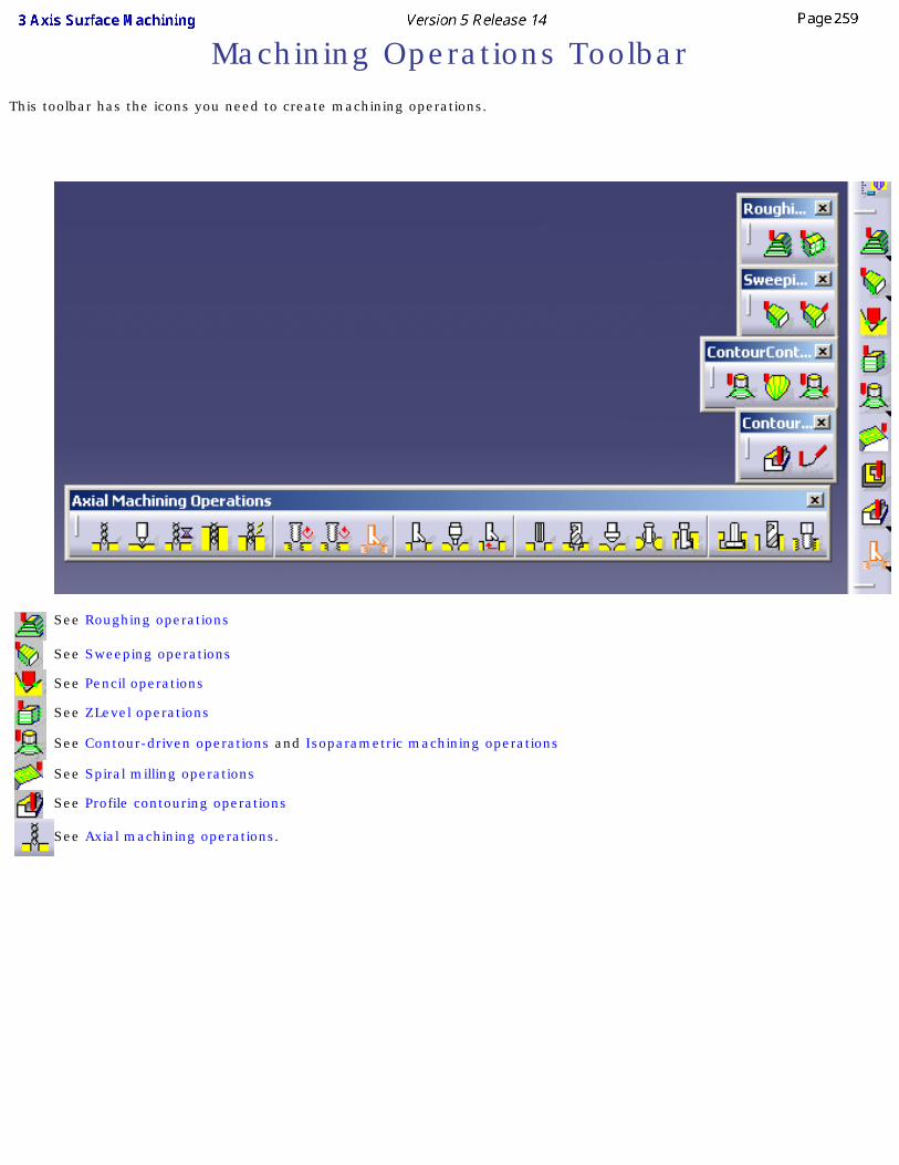
Machining Operations ToolbarThis toolbar has the icons you need to create machining operations.
See Roughing operations
See Sweeping operations
See Pencil operations
See ZLevel operations
See Contour-driven operations and Isoparametric machining operations
See Spiral milling operations
See Profile contouring operations
See Axial machining operations.
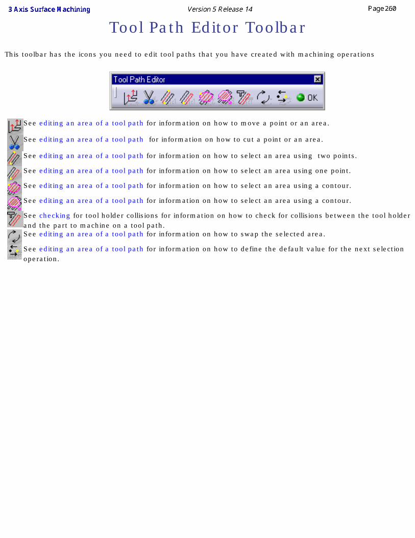
Tool Path Editor ToolbarThis toolbar has the icons you need to edit tool paths that you have created with machining operations
See editing an area of a tool path for information on how to move a point or an area.
See editing an area of a tool path for information on how to cut a point or an area.
See editing an area of a tool path for information on how to select an area using two points.
See editing an area of a tool path for information on how to select an area using one point.
See editing an area of a tool path for information on how to select an area using a contour.
See editing an area of a tool path for information on how to select an area using a contour.
See checking for tool holder collisions for information on how to check for collisions between the tool holder and the part to machine on a tool path.See editing an area of a tool path for information on how to swap the selected area.
See editing an area of a tool path for information on how to define the default value for the next selection operation.
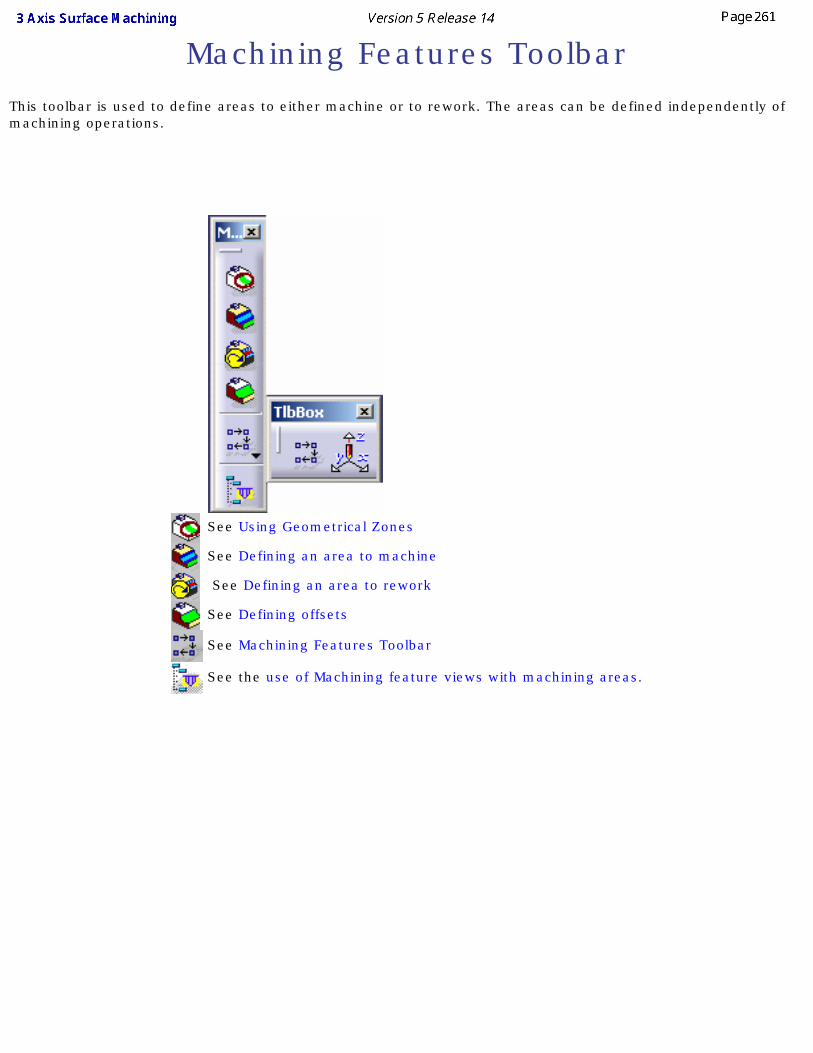
Machining Features ToolbarThis toolbar is used to define areas to either machine or to rework. The areas can be defined independently of machining operations.
See Using Geometrical Zones
See Defining an area to machine
See Defining an area to rework
See Defining offsets
See Machining Features Toolbar
See the use of Machining feature views with machining areas.
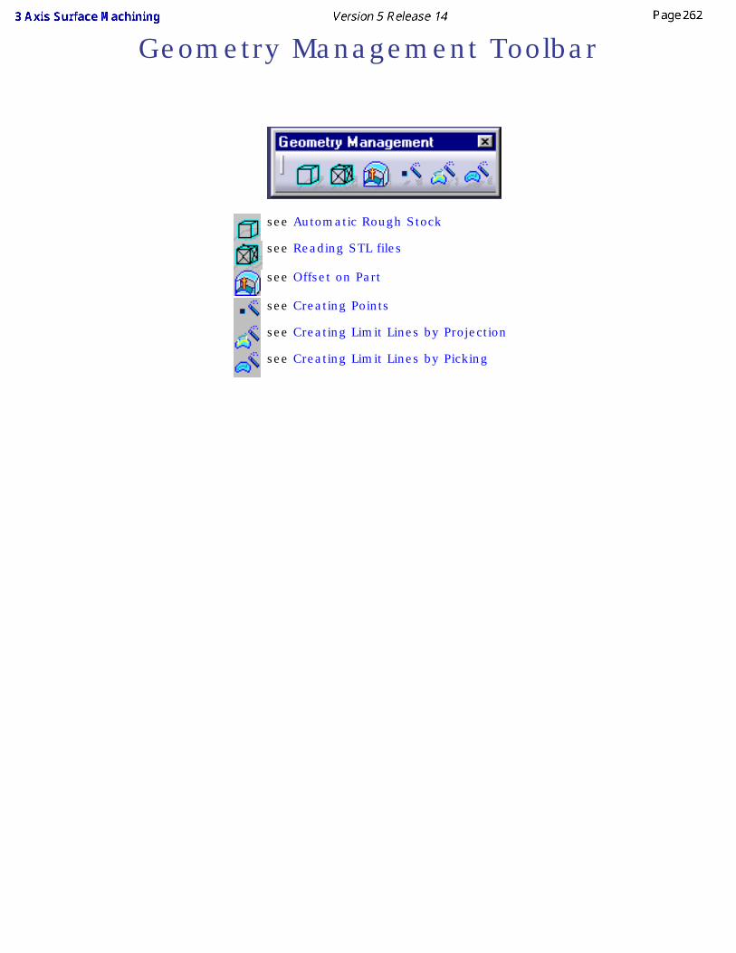
Geometry Management Toolbar
see Automatic Rough Stock
see Reading STL files
see Offset on Part
see Creating Points
see Creating Limit Lines by Projection
see Creating Limit Lines by Picking

Minimum Tool Length
see Compute Tool Gage on Assembly
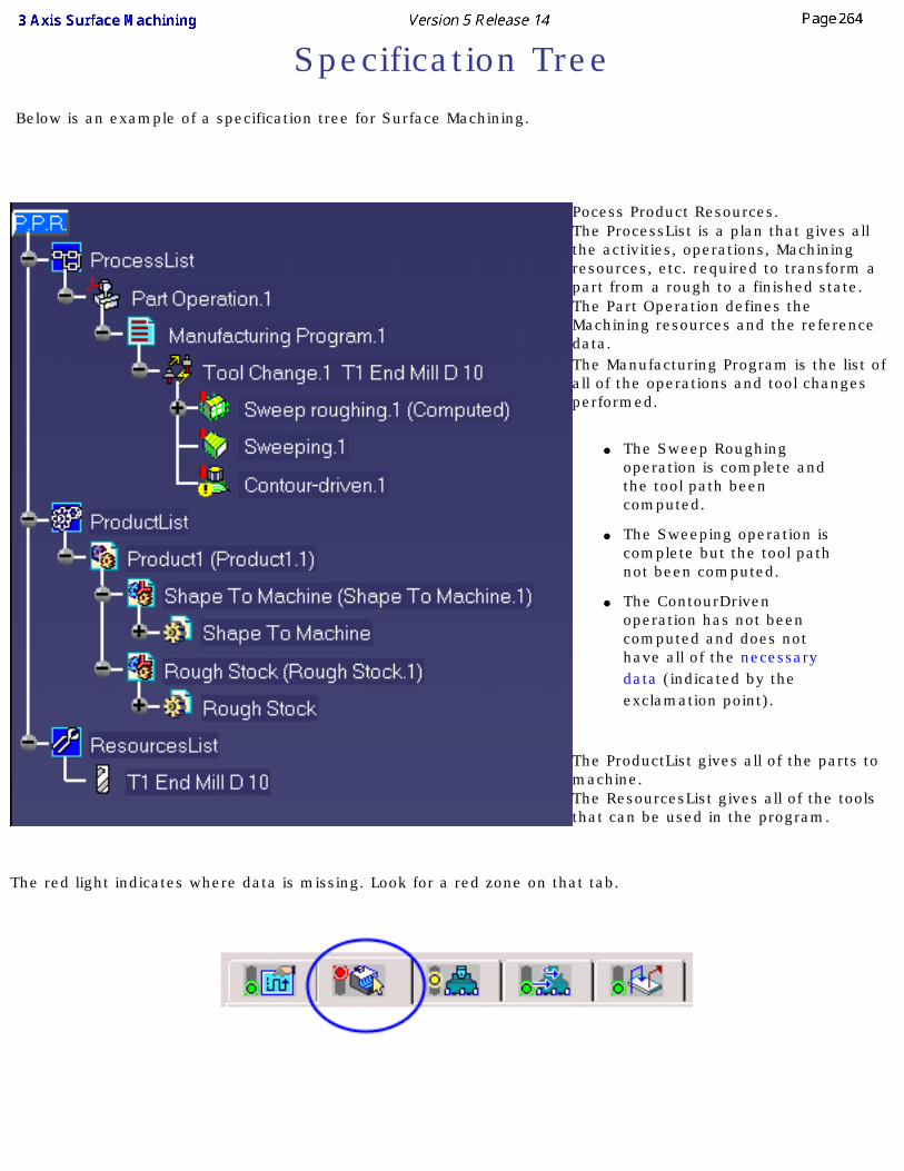
Specification Tree Below is an example of a specification tree for Surface Machining.
Pocess Product Resources.The ProcessList is a plan that gives all the activities, operations, Machining resources, etc. required to transform a part from a rough to a finished state.The Part Operation defines the Machining resources and the reference data.The Manufacturing Program is the list of all of the operations and tool changes performed.
● The Sweep Roughing operation is complete and the tool path been computed.
● The Sweeping operation is complete but the tool path not been computed.
● The ContourDriven operation has not been computed and does not have all of the necessary data (indicated by the exclamation point).
The ProductList gives all of the parts to machine.The ResourcesList gives all of the tools that can be used in the program.
The red light indicates where data is missing. Look for a red zone on that tab.
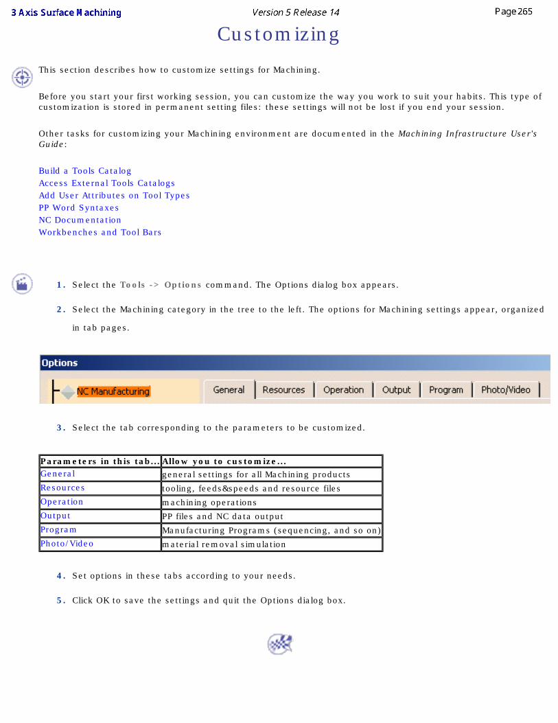
Customizing
This section describes how to customize settings for Machining.
Before you start your first working session, you can customize the way you work to suit your habits. This type of customization is stored in permanent setting files: these settings will not be lost if you end your session.
Other tasks for customizing your Machining environment are documented in the Machining Infrastructure User's Guide:
Build a Tools Catalog Access External Tools Catalogs Add User Attributes on Tool Types PP Word Syntaxes NC Documentation Workbenches and Tool Bars
1. Select the Tools -> Options command. The Options dialog box appears.
2. Select the Machining category in the tree to the left. The options for Machining settings appear, organized
in tab pages.
3. Select the tab corresponding to the parameters to be customized.
Parameters in this tab... Allow you to customize...General general settings for all Machining productsResources tooling, feeds&speeds and resource filesOperation machining operationsOutput PP files and NC data outputProgram Manufacturing Programs (sequencing, and so on)Photo/Video material removal simulation
4. Set options in these tabs according to your needs.
5. Click OK to save the settings and quit the Options dialog box.
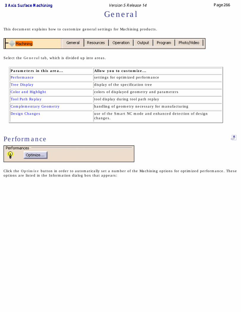
General
This document explains how to customize general settings for Machining products.
Select the General tab, which is divided up into areas.
Parameters in this area... Allow you to customize...
Performance settings for optimized performance
Tree Display display of the specification tree
Color and Highlight colors of displayed geometry and parameters
Tool Path Replay tool display during tool path replay
Complementary Geometry handling of geometry necessary for manufacturing
Design Changes use of the Smart NC mode and enhanced detection of design changes.
Performance
Click the Optimize button in order to automatically set a number of the Machining options for optimized performance. These options are listed in the Information dialog box that appears:
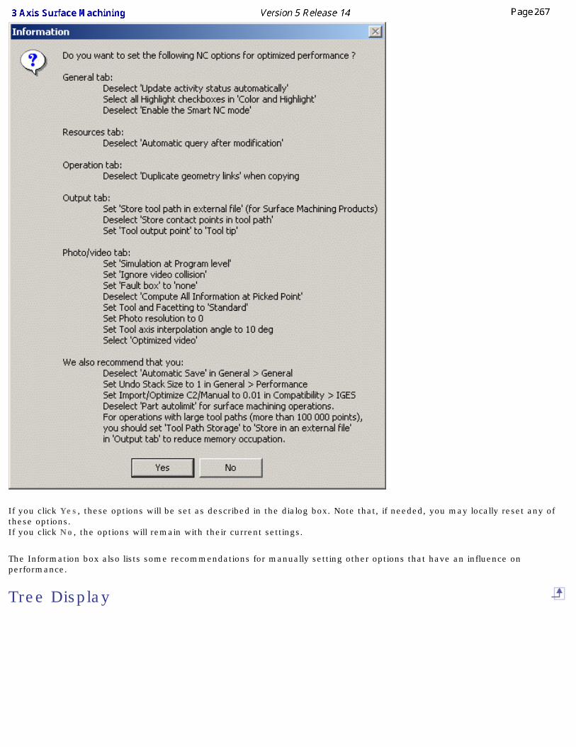
If you click Yes, these options will be set as described in the dialog box. Note that, if needed, you may locally reset any of these options.If you click No, the options will remain with their current settings.
The Information box also lists some recommendations for manually setting other options that have an influence on performance.
Tree Display
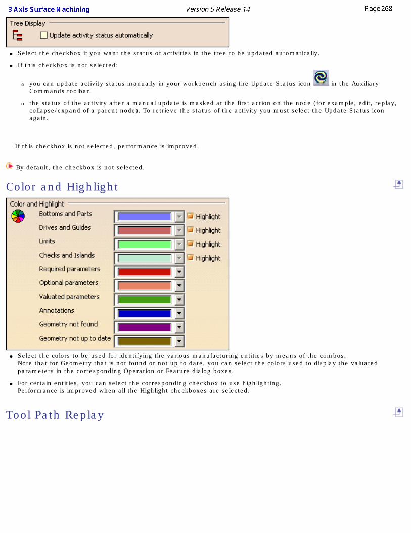
● Select the checkbox if you want the status of activities in the tree to be updated automatically.
● If this checkbox is not selected:
❍ you can update activity status manually in your workbench using the Update Status icon in the Auxiliary Commands toolbar.
❍ the status of the activity after a manual update is masked at the first action on the node (for example, edit, replay, collapse/expand of a parent node). To retrieve the status of the activity you must select the Update Status icon again.
If this checkbox is not selected, performance is improved.
By default, the checkbox is not selected.
Color and Highlight
● Select the colors to be used for identifying the various manufacturing entities by means of the combos. Note that for Geometry that is not found or not up to date, you can select the colors used to display the valuated parameters in the corresponding Operation or Feature dialog boxes.
● For certain entities, you can select the corresponding checkbox to use highlighting. Performance is improved when all the Highlight checkboxes are selected.
Tool Path Replay
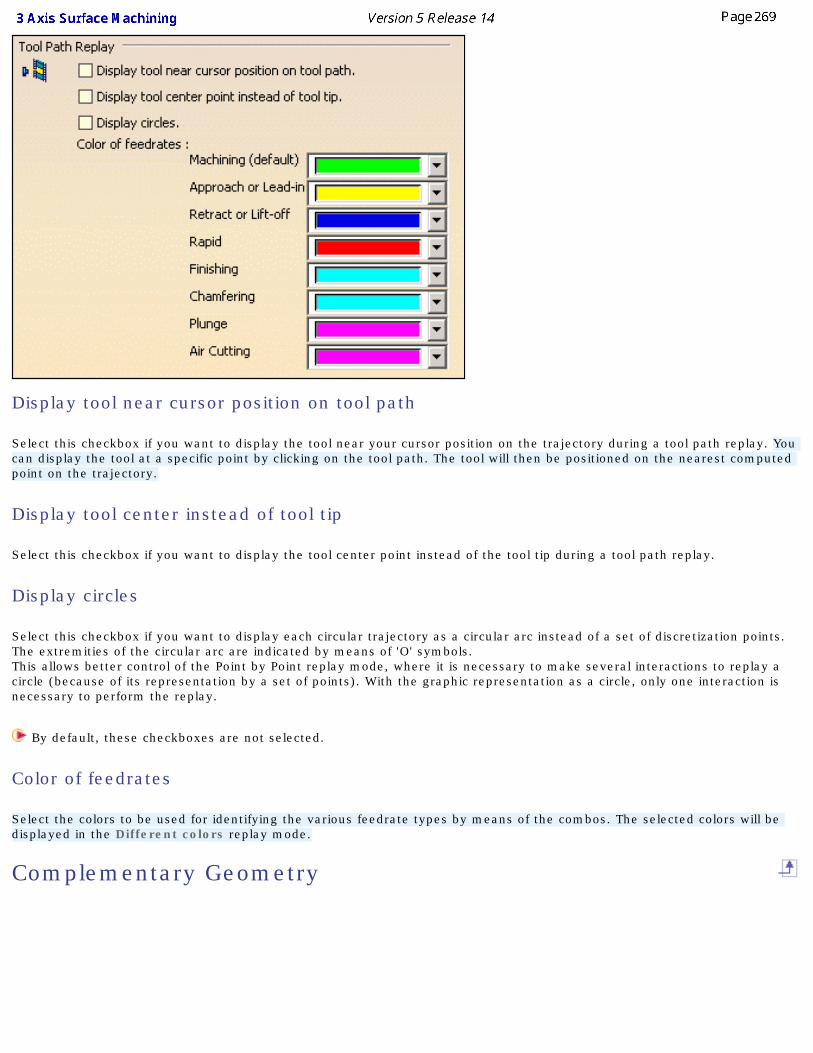
Display tool near cursor position on tool path
Select this checkbox if you want to display the tool near your cursor position on the trajectory during a tool path replay. You can display the tool at a specific point by clicking on the tool path. The tool will then be positioned on the nearest computed point on the trajectory.
Display tool center instead of tool tip
Select this checkbox if you want to display the tool center point instead of the tool tip during a tool path replay.
Display circles
Select this checkbox if you want to display each circular trajectory as a circular arc instead of a set of discretization points. The extremities of the circular arc are indicated by means of 'O' symbols.This allows better control of the Point by Point replay mode, where it is necessary to make several interactions to replay a circle (because of its representation by a set of points). With the graphic representation as a circle, only one interaction is necessary to perform the replay.
By default, these checkboxes are not selected.
Color of feedrates
Select the colors to be used for identifying the various feedrate types by means of the combos. The selected colors will be displayed in the Different colors replay mode.
Complementary Geometry
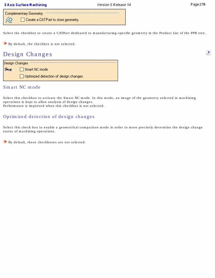
Select the checkbox to create a CATPart dedicated to manufacturing-specific geometry in the Product List of the PPR tree.
By default, the checkbox is not selected.
Design Changes
Smart NC mode
Select this checkbox to activate the Smart NC mode. In this mode, an image of the geometry selected in machining operations is kept to allow analysis of design changes.Performance is improved when this checkbox is not selected.
Optimized detection of design changes
Select this check box to enable a geometrical comparison mode in order to more precisely determine the design change status of machining operations.
By default, these checkboxes are not selected.
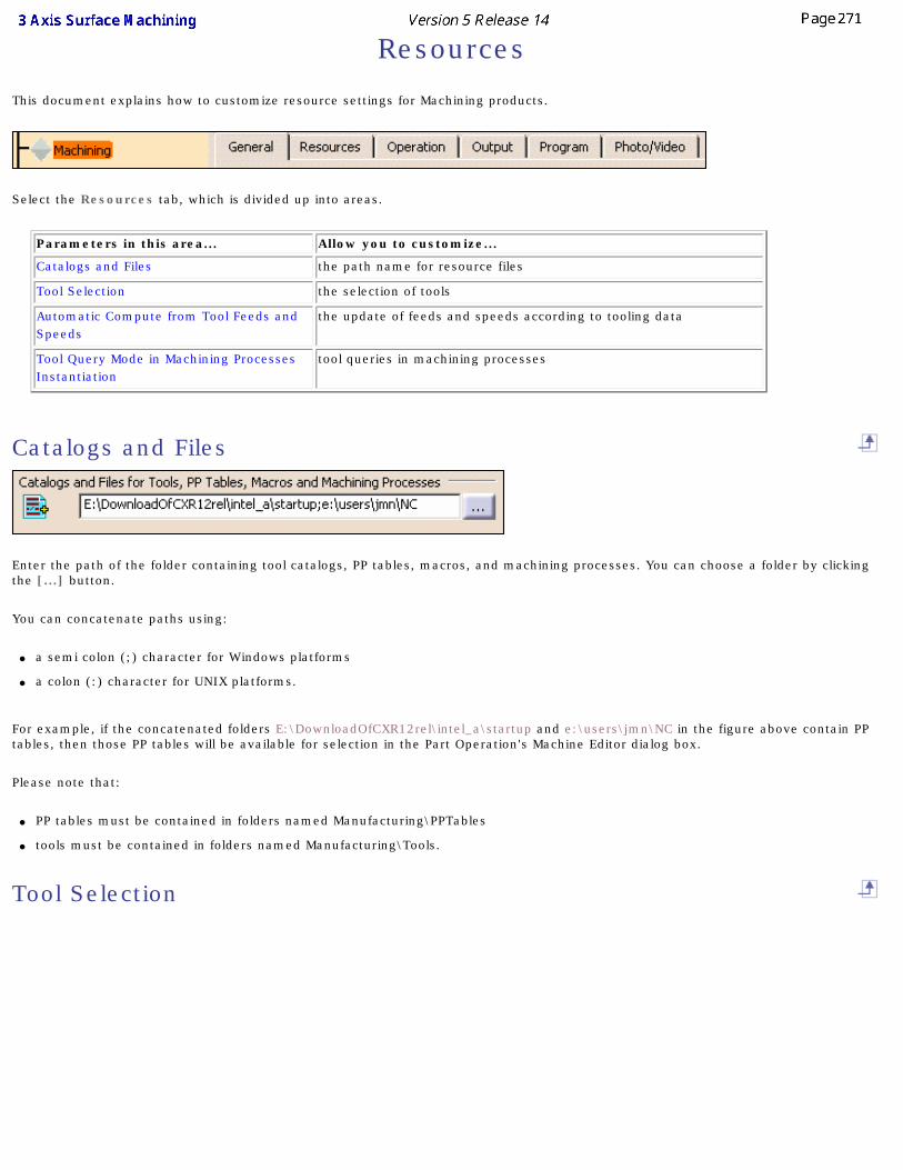
Resources
This document explains how to customize resource settings for Machining products.
Select the Resources tab, which is divided up into areas.
Parameters in this area... Allow you to customize...
Catalogs and Files the path name for resource files
Tool Selection the selection of tools
Automatic Compute from Tool Feeds and Speeds
the update of feeds and speeds according to tooling data
Tool Query Mode in Machining Processes Instantiation
tool queries in machining processes
Catalogs and Files
Enter the path of the folder containing tool catalogs, PP tables, macros, and machining processes. You can choose a folder by clicking the [...] button.
You can concatenate paths using:
● a semi colon (;) character for Windows platforms
● a colon (:) character for UNIX platforms.
For example, if the concatenated folders E:\DownloadOfCXR12rel\intel_a\startup and e:\users\jmn\NC in the figure above contain PP tables, then those PP tables will be available for selection in the Part Operation's Machine Editor dialog box.
Please note that:
● PP tables must be contained in folders named Manufacturing\PPTables
● tools must be contained in folders named Manufacturing\Tools.
Tool Selection
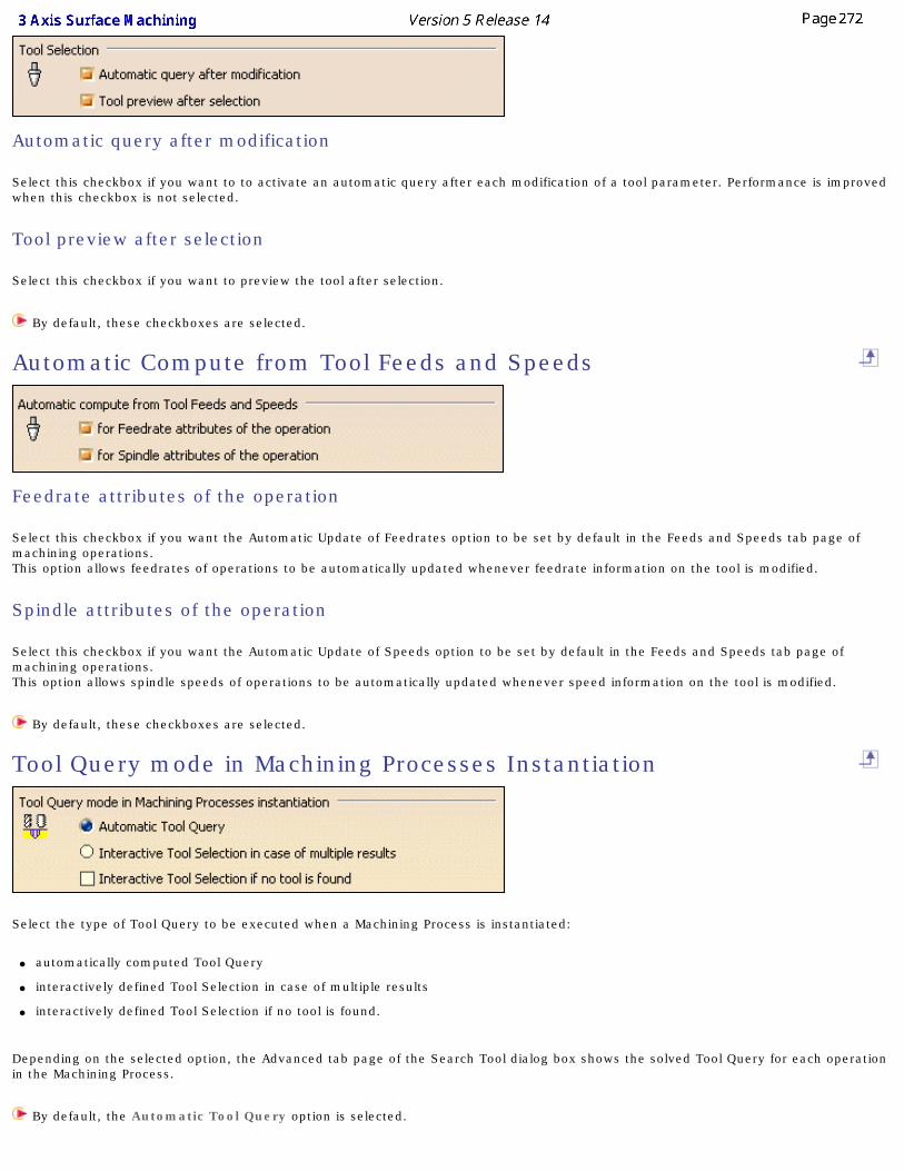
Automatic query after modification
Select this checkbox if you want to to activate an automatic query after each modification of a tool parameter. Performance is improved when this checkbox is not selected.
Tool preview after selection
Select this checkbox if you want to preview the tool after selection.
By default, these checkboxes are selected.
Automatic Compute from Tool Feeds and Speeds
Feedrate attributes of the operation
Select this checkbox if you want the Automatic Update of Feedrates option to be set by default in the Feeds and Speeds tab page of machining operations.This option allows feedrates of operations to be automatically updated whenever feedrate information on the tool is modified.
Spindle attributes of the operation
Select this checkbox if you want the Automatic Update of Speeds option to be set by default in the Feeds and Speeds tab page of machining operations.This option allows spindle speeds of operations to be automatically updated whenever speed information on the tool is modified.
By default, these checkboxes are selected.
Tool Query mode in Machining Processes Instantiation
Select the type of Tool Query to be executed when a Machining Process is instantiated:
● automatically computed Tool Query
● interactively defined Tool Selection in case of multiple results
● interactively defined Tool Selection if no tool is found.
Depending on the selected option, the Advanced tab page of the Search Tool dialog box shows the solved Tool Query for each operation in the Machining Process.
By default, the Automatic Tool Query option is selected.
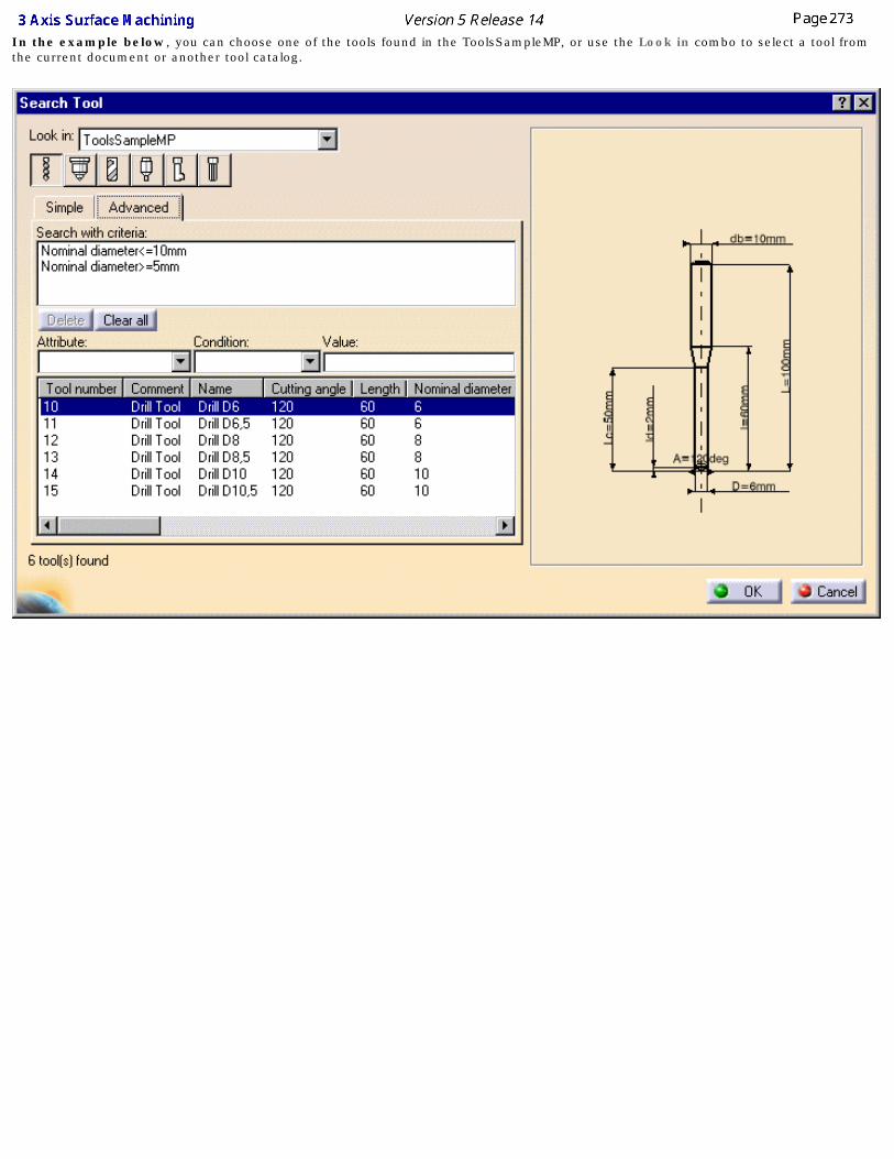
In the example below, you can choose one of the tools found in the ToolsSampleMP, or use the Look in combo to select a tool from the current document or another tool catalog.
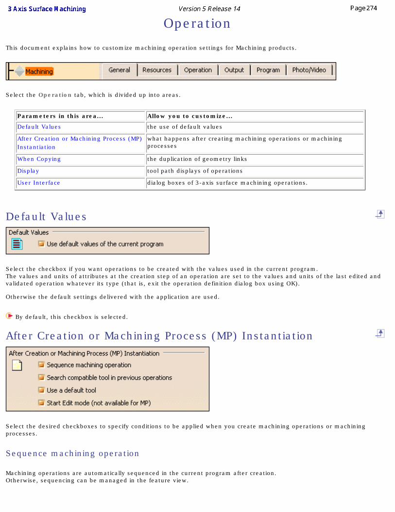
Operation
This document explains how to customize machining operation settings for Machining products.
Select the Operation tab, which is divided up into areas.
Parameters in this area... Allow you to customize...
Default Values the use of default values
After Creation or Machining Process (MP) Instantiation
what happens after creating machining operations or machining processes
When Copying the duplication of geometry links
Display tool path displays of operations
User Interface dialog boxes of 3-axis surface machining operations.
Default Values
Select the checkbox if you want operations to be created with the values used in the current program. The values and units of attributes at the creation step of an operation are set to the values and units of the last edited and validated operation whatever its type (that is, exit the operation definition dialog box using OK).
Otherwise the default settings delivered with the application are used.
By default, this checkbox is selected.
After Creation or Machining Process (MP) Instantiation
Select the desired checkboxes to specify conditions to be applied when you create machining operations or machining processes.
Sequence machining operation
Machining operations are automatically sequenced in the current program after creation. Otherwise, sequencing can be managed in the feature view.
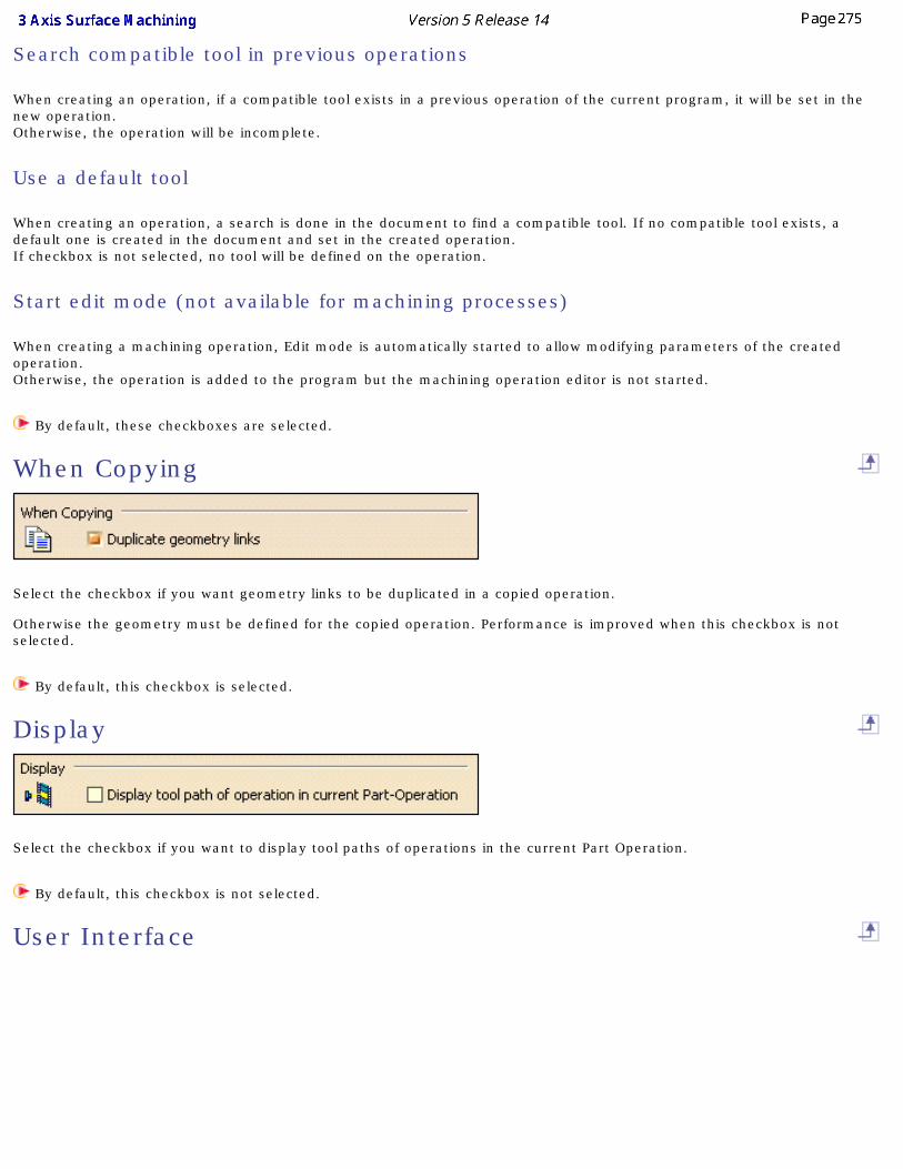
Search compatible tool in previous operations
When creating an operation, if a compatible tool exists in a previous operation of the current program, it will be set in the new operation. Otherwise, the operation will be incomplete.
Use a default tool
When creating an operation, a search is done in the document to find a compatible tool. If no compatible tool exists, a default one is created in the document and set in the created operation.If checkbox is not selected, no tool will be defined on the operation.
Start edit mode (not available for machining processes)
When creating a machining operation, Edit mode is automatically started to allow modifying parameters of the created operation.Otherwise, the operation is added to the program but the machining operation editor is not started.
By default, these checkboxes are selected.
When Copying
Select the checkbox if you want geometry links to be duplicated in a copied operation.
Otherwise the geometry must be defined for the copied operation. Performance is improved when this checkbox is not selected.
By default, this checkbox is selected.
Display
Select the checkbox if you want to display tool paths of operations in the current Part Operation.
By default, this checkbox is not selected.
User Interface

Select the checkbox if you want to have the possibility of simplifying the dialog boxes of machining operations (that is, you can display the minimum number of parameters necessary for a correct tool path). This setting is available for 3-axis surface machining operations only.
By default, this checkbox is not selected.
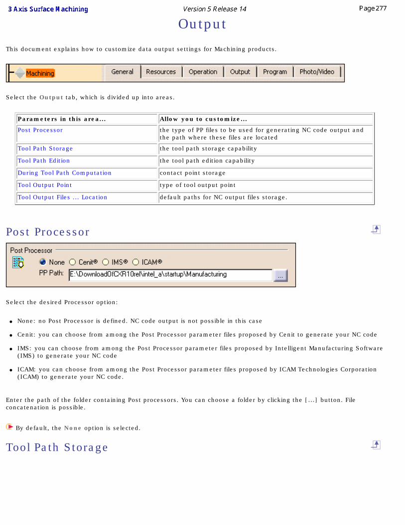
Output
This document explains how to customize data output settings for Machining products.
Select the Output tab, which is divided up into areas.
Parameters in this area... Allow you to customize...
Post Processor the type of PP files to be used for generating NC code output and the path where these files are located
Tool Path Storage the tool path storage capability
Tool Path Edition the tool path edition capability
During Tool Path Computation contact point storage
Tool Output Point type of tool output point
Tool Output Files ... Location default paths for NC output files storage.
Post Processor
Select the desired Processor option:
● None: no Post Processor is defined. NC code output is not possible in this case
● Cenit: you can choose from among the Post Processor parameter files proposed by Cenit to generate your NC code
● IMS: you can choose from among the Post Processor parameter files proposed by Intelligent Manufacturing Software (IMS) to generate your NC code
● ICAM: you can choose from among the Post Processor parameter files proposed by ICAM Technologies Corporation (ICAM) to generate your NC code.
Enter the path of the folder containing Post processors. You can choose a folder by clicking the [...] button. File concatenation is possible.
By default, the None option is selected.
Tool Path Storage
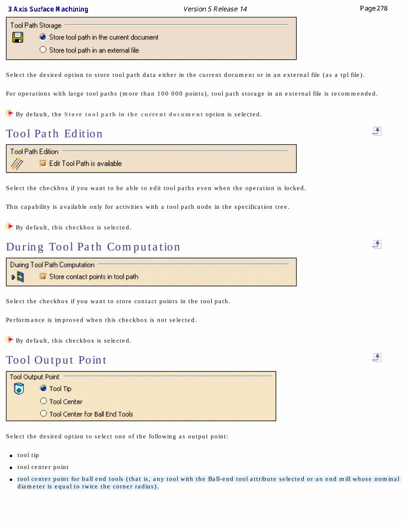
Select the desired option to store tool path data either in the current document or in an external file (as a tpl file).
For operations with large tool paths (more than 100 000 points), tool path storage in an external file is recommended.
By default, the Store tool path in the current document option is selected.
Tool Path Edition
Select the checkbox if you want to be able to edit tool paths even when the operation is locked.
This capability is available only for activities with a tool path node in the specification tree.
By default, this checkbox is selected.
During Tool Path Computation
Select the checkbox if you want to store contact points in the tool path.
Performance is improved when this checkbox is not selected.
By default, this checkbox is selected.
Tool Output Point
Select the desired option to select one of the following as output point:
● tool tip
● tool center point
● tool center point for ball end tools (that is, any tool with the Ball-end tool attribute selected or an end mill whose nominal diameter is equal to twice the corner radius).
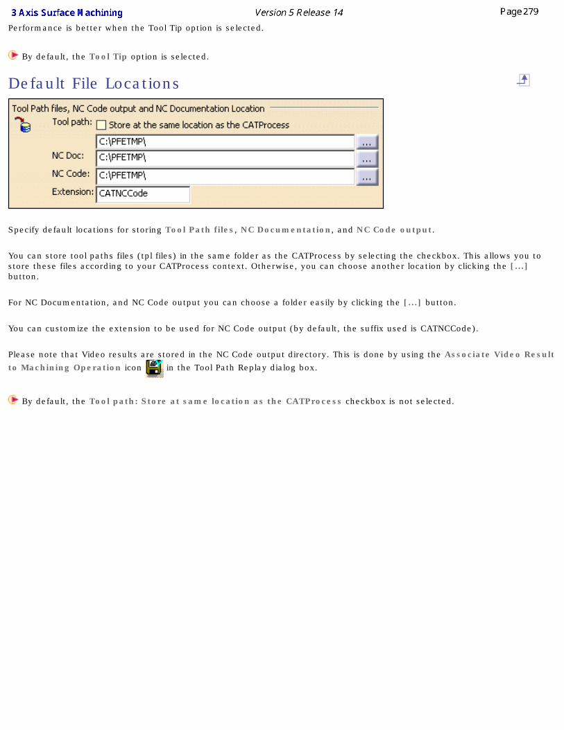
Performance is better when the Tool Tip option is selected.
By default, the Tool Tip option is selected.
Default File Locations
Specify default locations for storing Tool Path files, NC Documentation, and NC Code output.
You can store tool paths files (tpl files) in the same folder as the CATProcess by selecting the checkbox. This allows you to store these files according to your CATProcess context. Otherwise, you can choose another location by clicking the [...] button.
For NC Documentation, and NC Code output you can choose a folder easily by clicking the [...] button.
You can customize the extension to be used for NC Code output (by default, the suffix used is CATNCCode).
Please note that Video results are stored in the NC Code output directory. This is done by using the Associate Video Result
to Machining Operation icon in the Tool Path Replay dialog box.
By default, the Tool path: Store at same location as the CATProcess checkbox is not selected.
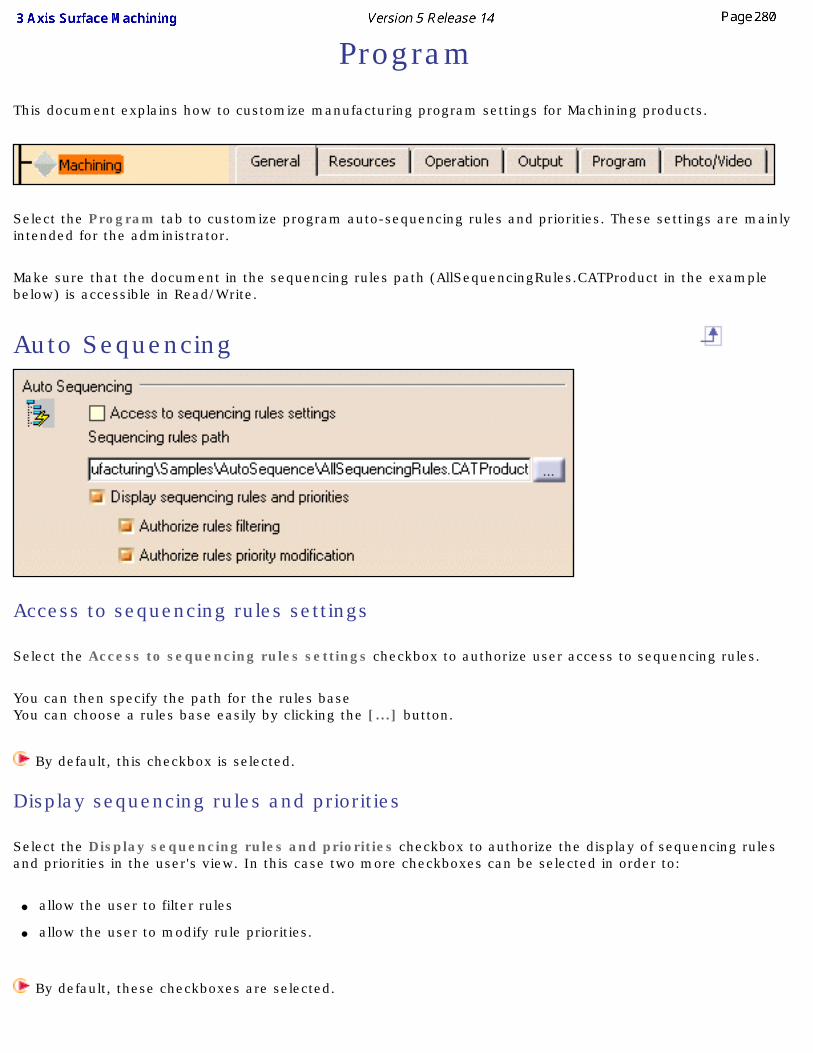
Program
This document explains how to customize manufacturing program settings for Machining products.
Select the Program tab to customize program auto-sequencing rules and priorities. These settings are mainly intended for the administrator.
Make sure that the document in the sequencing rules path (AllSequencingRules.CATProduct in the example below) is accessible in Read/Write.
Auto Sequencing
Access to sequencing rules settings
Select the Access to sequencing rules settings checkbox to authorize user access to sequencing rules.
You can then specify the path for the rules base You can choose a rules base easily by clicking the [...] button.
By default, this checkbox is selected.
Display sequencing rules and priorities
Select the Display sequencing rules and priorities checkbox to authorize the display of sequencing rules and priorities in the user's view. In this case two more checkboxes can be selected in order to:
● allow the user to filter rules
● allow the user to modify rule priorities.
By default, these checkboxes are selected.
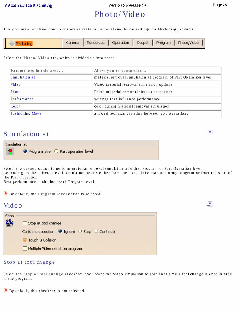
Photo/Video
This document explains how to customize material removal simulation settings for Machining products.
Select the Photo/Video tab, which is divided up into areas.
Parameters in this area... Allow you to customize...
Simulation at material removal simulation at program of Part Operation level
Video Video material removal simulation options
Photo Photo material removal simulation options
Performance settings that influence performance
Color color during material removal simulation
Positioning Move allowed tool axis variation between two operations
Simulation at
Select the desired option to perform material removal simulation at either Program or Part Operation level. Depending on the selected level, simulation begins either from the start of the manufacturing program or from the start of the Part Operation. Best performance is obtained with Program level.
By default, the Program level option is selected.
Video
Stop at tool change
Select the Stop at tool change checkbox if you want the Video simulation to stop each time a tool change is encountered in the program.
By default, this checkbox is not selected.
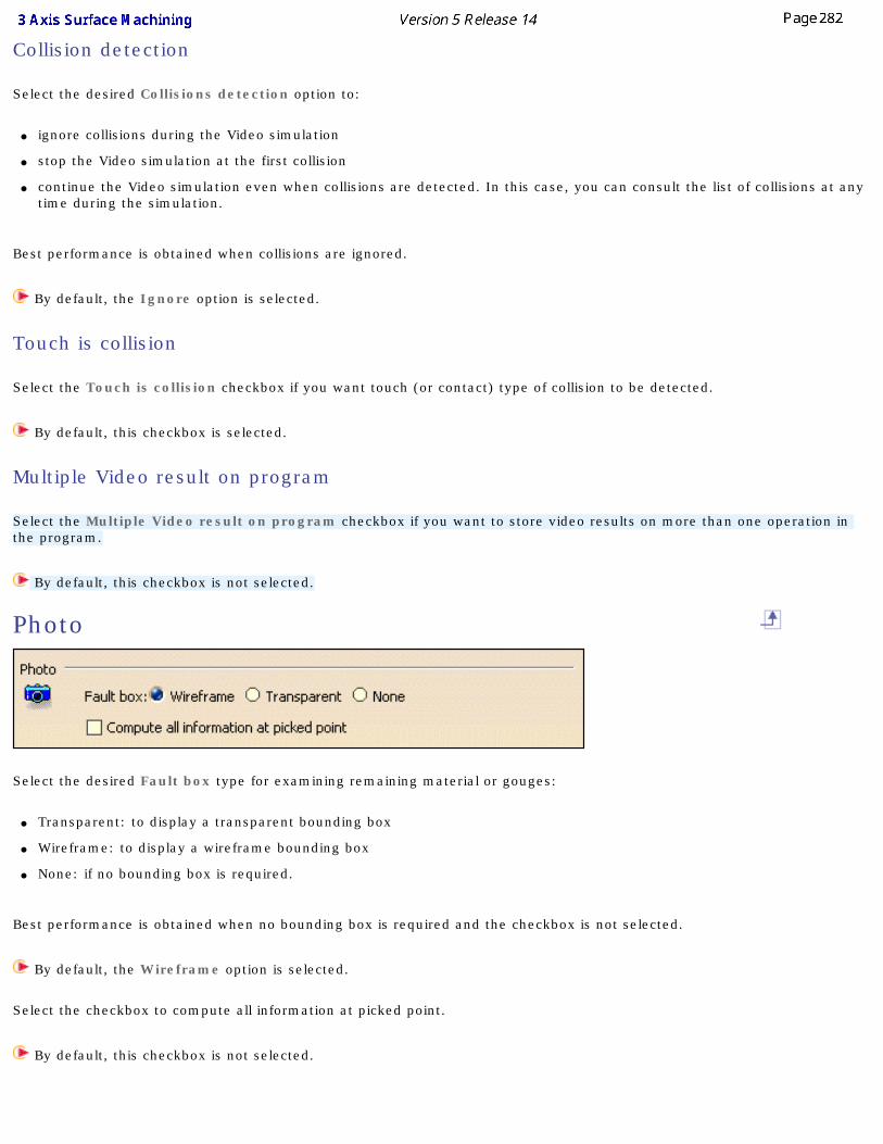
Collision detection
Select the desired Collisions detection option to:
● ignore collisions during the Video simulation
● stop the Video simulation at the first collision
● continue the Video simulation even when collisions are detected. In this case, you can consult the list of collisions at any time during the simulation.
Best performance is obtained when collisions are ignored.
By default, the Ignore option is selected.
Touch is collision
Select the Touch is collision checkbox if you want touch (or contact) type of collision to be detected.
By default, this checkbox is selected.
Multiple Video result on program
Select the Multiple Video result on program checkbox if you want to store video results on more than one operation in the program.
By default, this checkbox is not selected.
Photo
Select the desired Fault box type for examining remaining material or gouges:
● Transparent: to display a transparent bounding box
● Wireframe: to display a wireframe bounding box
● None: if no bounding box is required.
Best performance is obtained when no bounding box is required and the checkbox is not selected.
By default, the Wireframe option is selected.
Select the checkbox to compute all information at picked point.
By default, this checkbox is not selected.
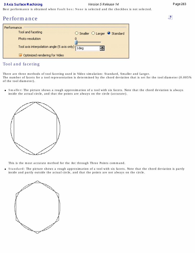
Best performance is obtained when Fault box: None is selected and the checkbox is not selected.
Performance
Tool and faceting
There are three methods of tool faceting used in Video simulation: Standard, Smaller and Larger. The number of facets for a tool representation is determined by the chord deviation that is set for the tool diameter (0.005% of the tool diameter).
● Smaller: The picture shows a rough approximation of a tool with six facets. Note that the chord deviation is always inside the actual circle, and that the points are always on the circle (accurate).
This is the most accurate method for the Arc through Three Points command.
● Standard: The picture shows a rough approximation of a tool with six facets. Note that the chord deviation is partly inside and partly outside the actual circle, and that the points are not always on the circle.
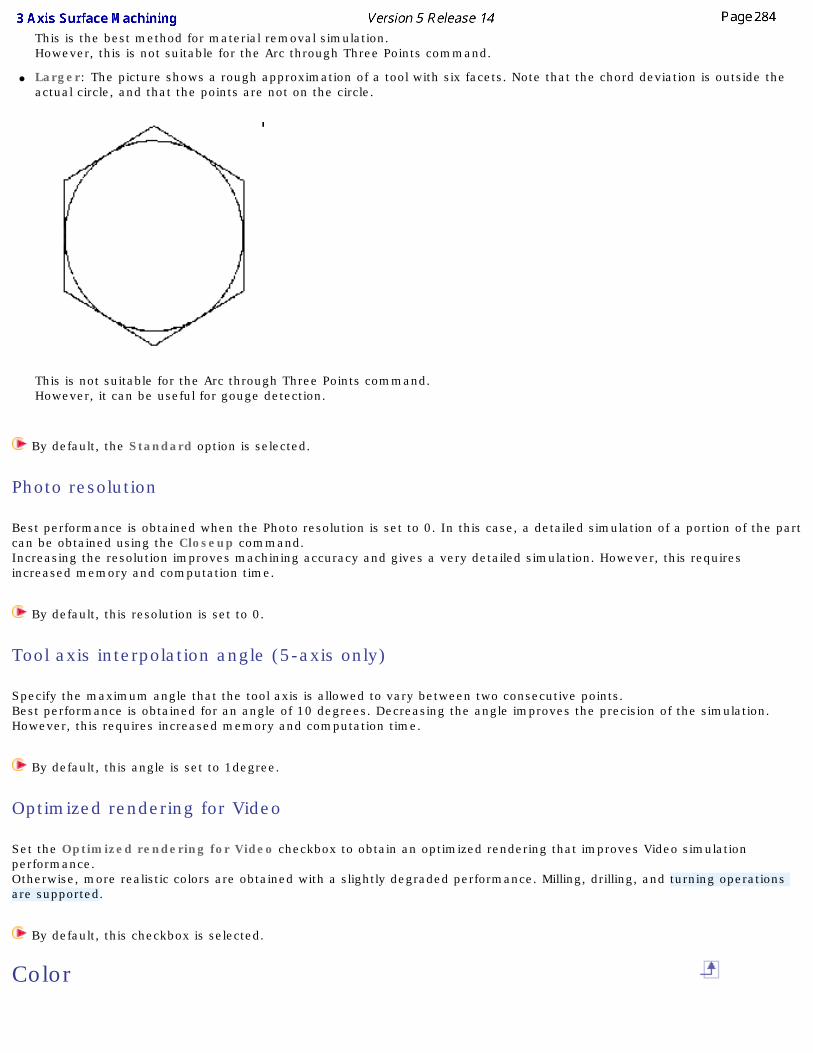
This is the best method for material removal simulation. However, this is not suitable for the Arc through Three Points command.
● Larger: The picture shows a rough approximation of a tool with six facets. Note that the chord deviation is outside the actual circle, and that the points are not on the circle.
This is not suitable for the Arc through Three Points command.However, it can be useful for gouge detection.
By default, the Standard option is selected.
Photo resolution
Best performance is obtained when the Photo resolution is set to 0. In this case, a detailed simulation of a portion of the part can be obtained using the Closeup command.Increasing the resolution improves machining accuracy and gives a very detailed simulation. However, this requires increased memory and computation time.
By default, this resolution is set to 0.
Tool axis interpolation angle (5-axis only)
Specify the maximum angle that the tool axis is allowed to vary between two consecutive points. Best performance is obtained for an angle of 10 degrees. Decreasing the angle improves the precision of the simulation. However, this requires increased memory and computation time.
By default, this angle is set to 1degree.
Optimized rendering for Video
Set the Optimized rendering for Video checkbox to obtain an optimized rendering that improves Video simulation performance.Otherwise, more realistic colors are obtained with a slightly degraded performance. Milling, drilling, and turning operations are supported.
By default, this checkbox is selected.
Color
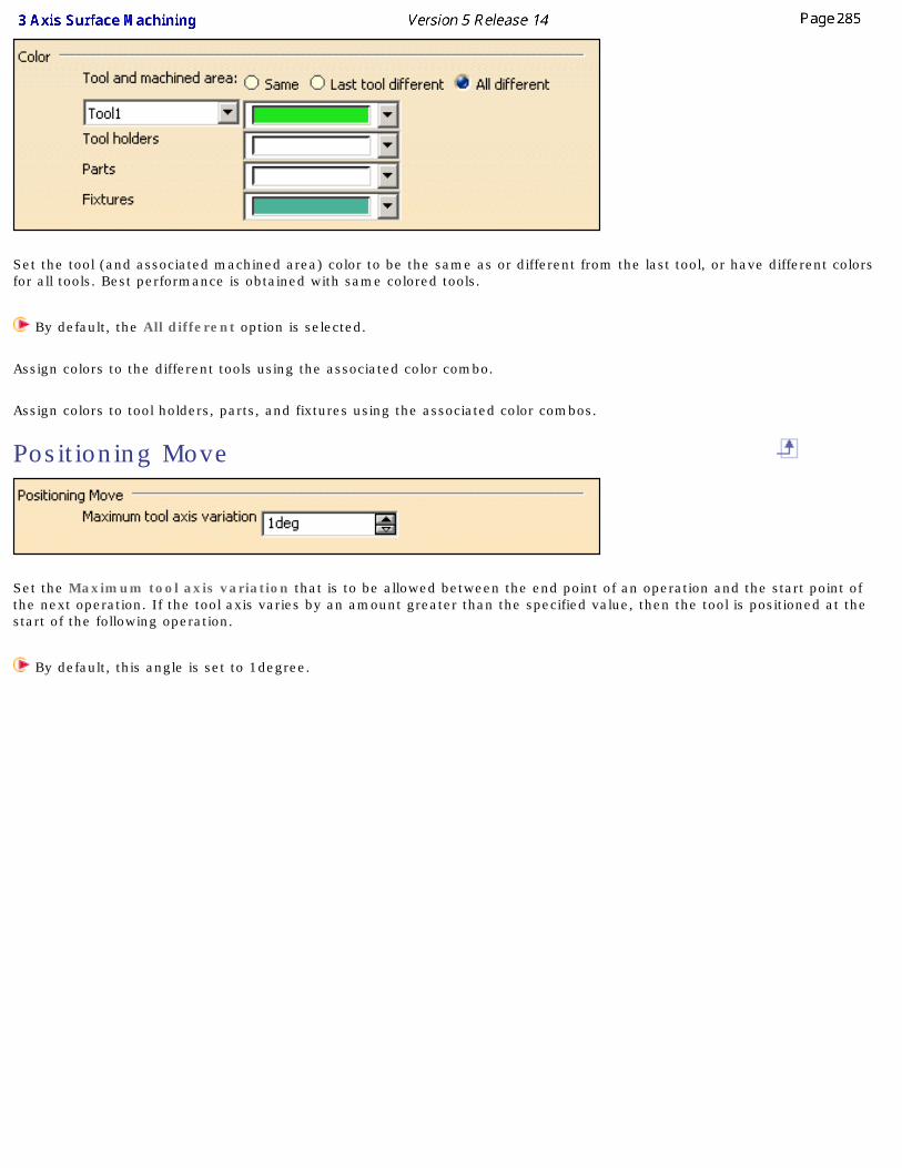
Set the tool (and associated machined area) color to be the same as or different from the last tool, or have different colors for all tools. Best performance is obtained with same colored tools.
By default, the All different option is selected.
Assign colors to the different tools using the associated color combo.
Assign colors to tool holders, parts, and fixtures using the associated color combos.
Positioning Move
Set the Maximum tool axis variation that is to be allowed between the end point of an operation and the start point of the next operation. If the tool axis varies by an amount greater than the specified value, then the tool is positioned at the start of the following operation.
By default, this angle is set to 1degree.
Reference InformationReference information that is specific to the 3 Axis Surface Machining product can be found in this section.
Sweep Roughing ParametersRoughing ParametersSweeping Parameters
ZLevel ParametersSpiral Milling Parameters
Contour-driven ParametersPencil Parameters
Isoparametric Machining ParametersTool Path Editor Parameters
Machining/Slope Areas ParametersMacros Parameters
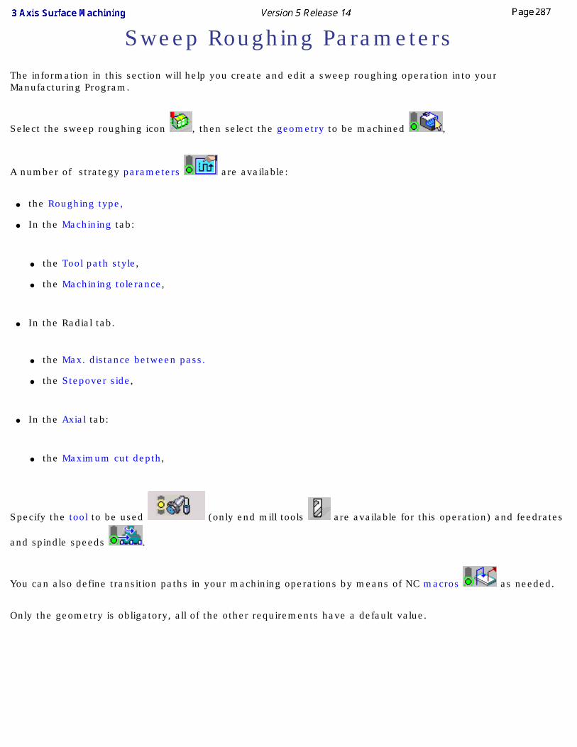
Sweep Roughing ParametersThe information in this section will help you create and edit a sweep roughing operation into your Manufacturing Program.
Select the sweep roughing icon , then select the geometry to be machined ,
A number of strategy parameters are available:
● the Roughing type,
● In the Machining tab:
● the Tool path style,
● the Machining tolerance,
● In the Radial tab.
● the Max. distance between pass.
● the Stepover side,
● In the Axial tab:
● the Maximum cut depth,
Specify the tool to be used (only end mill tools are available for this operation) and feedrates
and spindle speeds .
You can also define transition paths in your machining operations by means of NC macros as needed.
Only the geometry is obligatory, all of the other requirements have a default value.
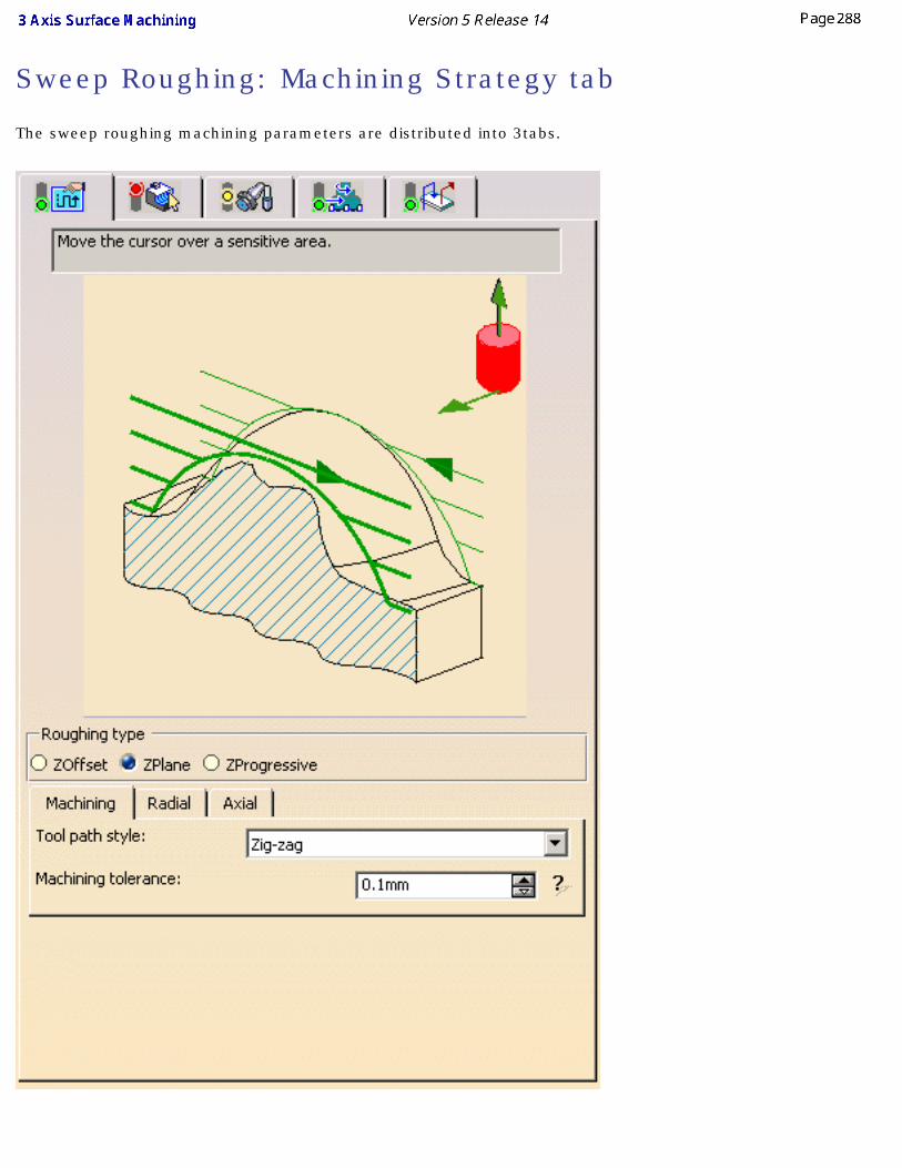
Sweep Roughing: Machining Strategy tab
The sweep roughing machining parameters are distributed into 3tabs.
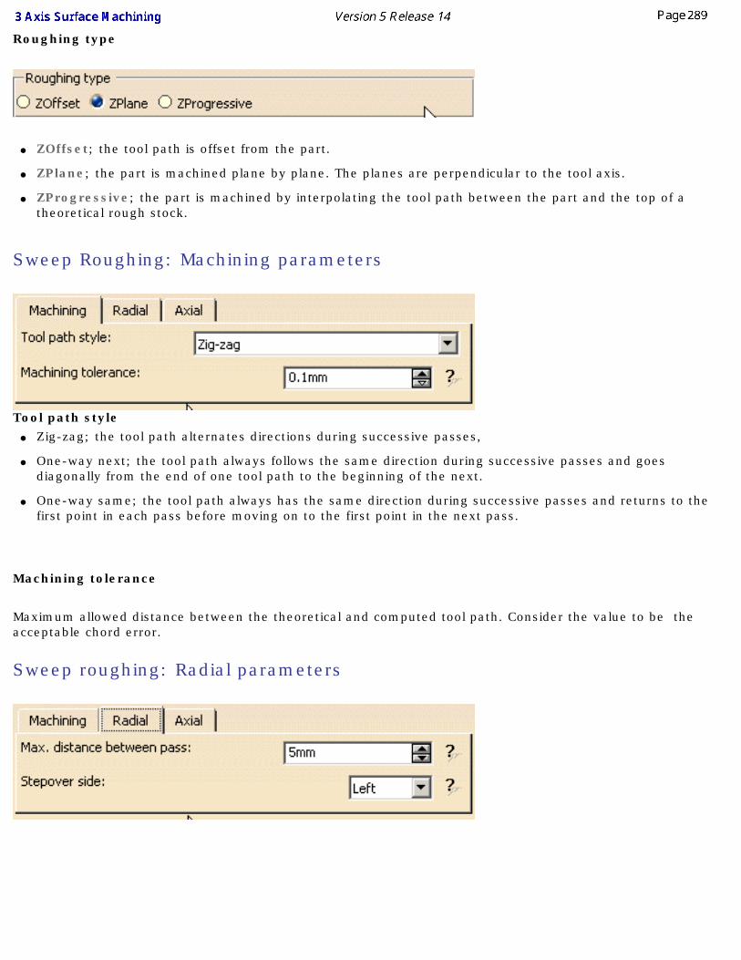
Roughing type
● ZOffset; the tool path is offset from the part.
● ZPlane; the part is machined plane by plane. The planes are perpendicular to the tool axis.
● ZProgressive; the part is machined by interpolating the tool path between the part and the top of a theoretical rough stock.
Sweep Roughing: Machining parameters
Tool path style● Zig-zag; the tool path alternates directions during successive passes,
● One-way next; the tool path always follows the same direction during successive passes and goes diagonally from the end of one tool path to the beginning of the next.
● One-way same; the tool path always has the same direction during successive passes and returns to the first point in each pass before moving on to the first point in the next pass.
Machining tolerance
Maximum allowed distance between the theoretical and computed tool path. Consider the value to be the acceptable chord error.
Sweep roughing: Radial parameters
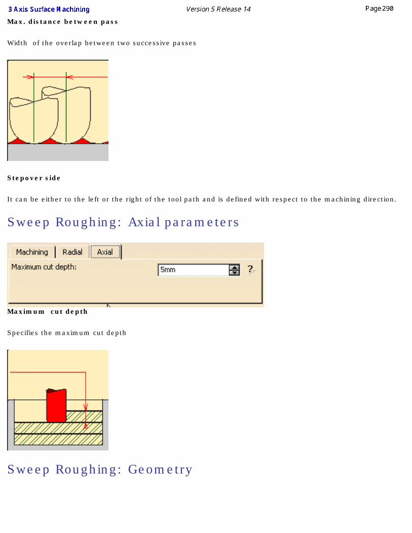
Max. distance between pass
Width of the overlap between two successive passes
Stepover side
It can be either to the left or the right of the tool path and is defined with respect to the machining direction.
Sweep Roughing: Axial parameters
Maximum cut depth
Specifies the maximum cut depth
Sweep Roughing: Geometry
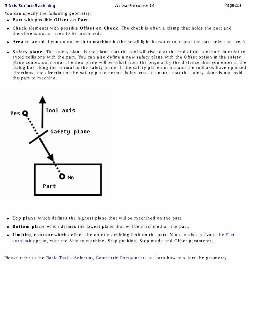
You can specify the following geometry: ● Part with possible Offset on Part.
● Check elements with possible Offset on Check. The check is often a clamp that holds the part and therefore is not an area to be machined.
● Area to avoid if you do not wish to machine it (the small light brown corner near the part selection area).
● Safety plane. The safety plane is the plane that the tool will rise to at the end of the tool path in order to
avoid collisions with the part. You can also define a new safety plane with the Offset option in the safety plane contextual menu. The new plane will be offset from the original by the distance that you enter in the dialog box along the normal to the safety plane. If the safety plane normal and the tool axis have opposed directions, the direction of the safety plane normal is inverted to ensure that the safety plane is not inside the part to machine.
● Top plane which defines the highest plane that will be machined on the part,
● Bottom plane which defines the lowest plane that will be machined on the part,
● Limiting contour which defines the outer machining limit on the part. You can also activate the Part autolimit option, with the Side to machine, Stop position, Stop mode and Offset parameters.
Please refer to the Basic Task - Selecting Geometric Components to learn how to select the geometry.
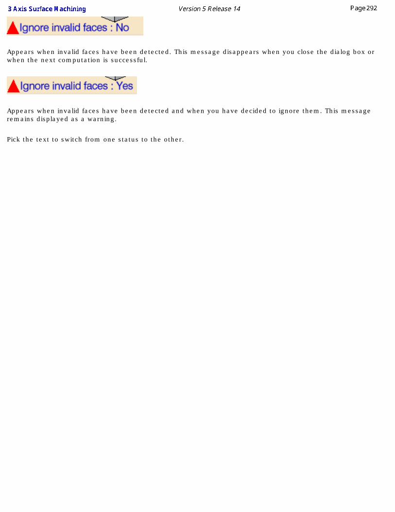
Appears when invalid faces have been detected. This message disappears when you close the dialog box or when the next computation is successful.
Appears when invalid faces have been detected and when you have decided to ignore them. This message remains displayed as a warning.
Pick the text to switch from one status to the other.
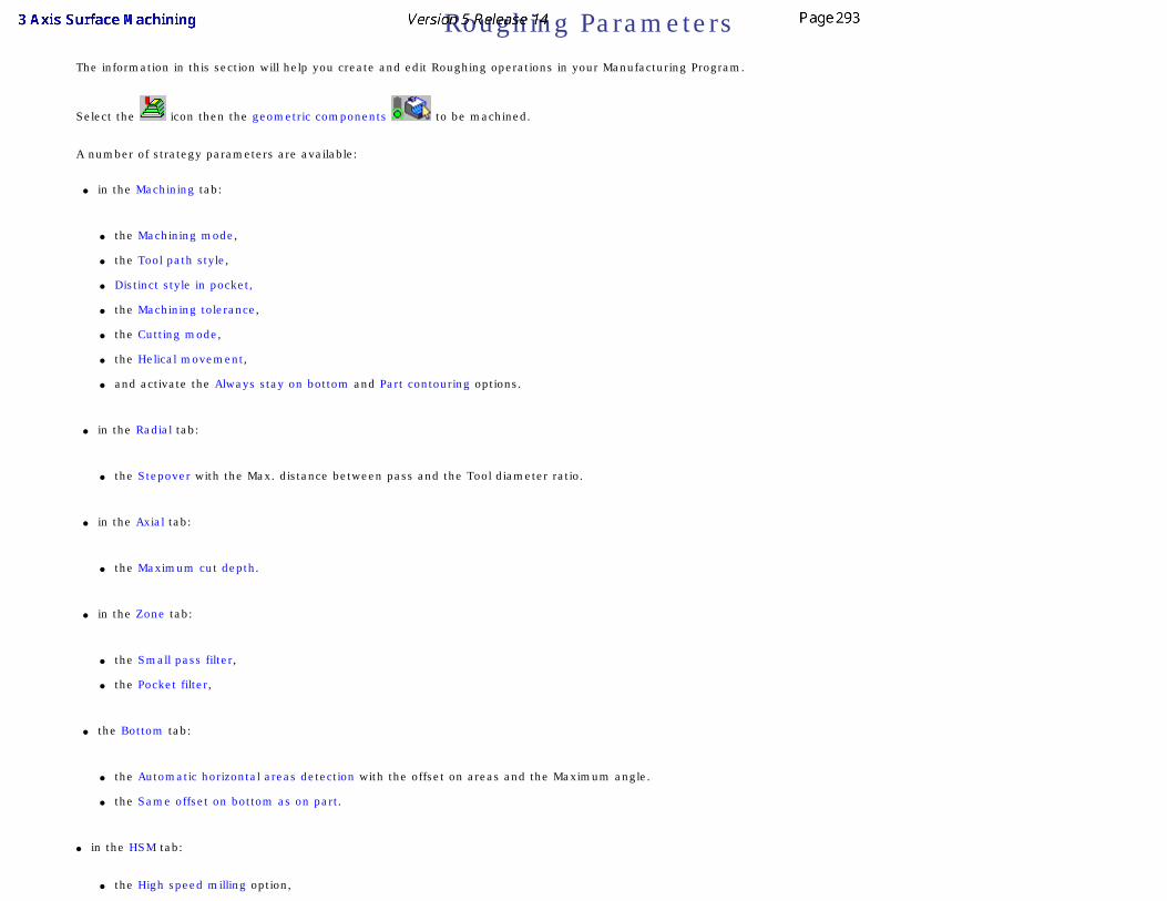
Roughing ParametersThe information in this section will help you create and edit Roughing operations in your Manufacturing Program.
Select the icon then the geometric components to be machined.
A number of strategy parameters are available:
● in the Machining tab:
● the Machining mode,
● the Tool path style,
● Distinct style in pocket,
● the Machining tolerance,
● the Cutting mode,
● the Helical movement,
● and activate the Always stay on bottom and Part contouring options.
● in the Radial tab:
● the Stepover with the Max. distance between pass and the Tool diameter ratio.
● in the Axial tab:
● the Maximum cut depth.
● in the Zone tab:
● the Small pass filter,
● the Pocket filter,
● the Bottom tab:
● the Automatic horizontal areas detection with the offset on areas and the Maximum angle.
● the Same offset on bottom as on part.
● in the HSM tab:
● the High speed milling option,
● its Corner radius.
Specify the tool to be used (only end mill tools are available for this operation) and speeds and rates .
You can also define transition paths in your machining operations by means of NC macros as needed. These transition paths are useful to:
● optimize retract distances,
● set the Approach and Retract parameters.
Only the geometry is obligatory, all of the other requirements have a default value.
Roughing: Machining Strategy tab
The roughing strategy parameters are distributed into 6 tabs. By default, all 6 tabs are displayed with all their parameters. However, current operations only require a reduced list of those parameters.
Push the <<Less button to display only those current parameters. The Zone and the Bottom tab are hidden, as well as the Variable cut depths button in the Axial tab.
Push the More>> button to re-display all parameters.
You can also use the modal option User Interface Simplified mode in the Tools -> Options -> Machining -> Operation tab.
By default, all tabs and all parameters are displayed: Press <<Less to display a reduced list of tabs and parameters:
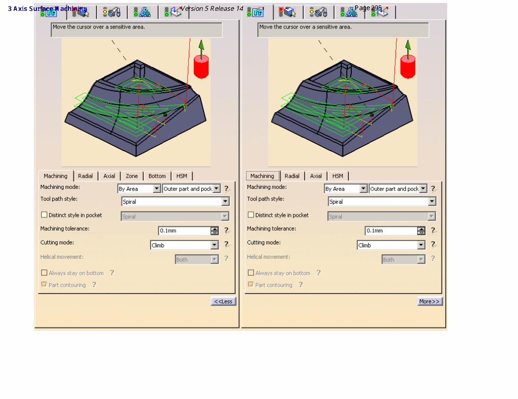
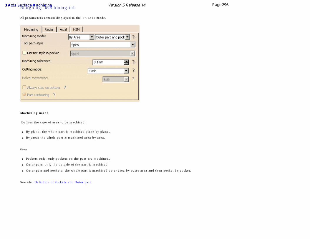
Roughing: Machining tab
All parameters remain displayed in the <<Less mode.
Machining mode
Defines the type of area to be machined:
● By plane: the whole part is machined plane by plane,
● By area: the whole part is machined area by area,
then
● Pockets only: only pockets on the part are machined,
● Outer part: only the outside of the part is machined,
● Outer part and pockets: the whole part is machined outer area by outer area and then pocket by pocket.
See also Definition of Pockets and Outer part.
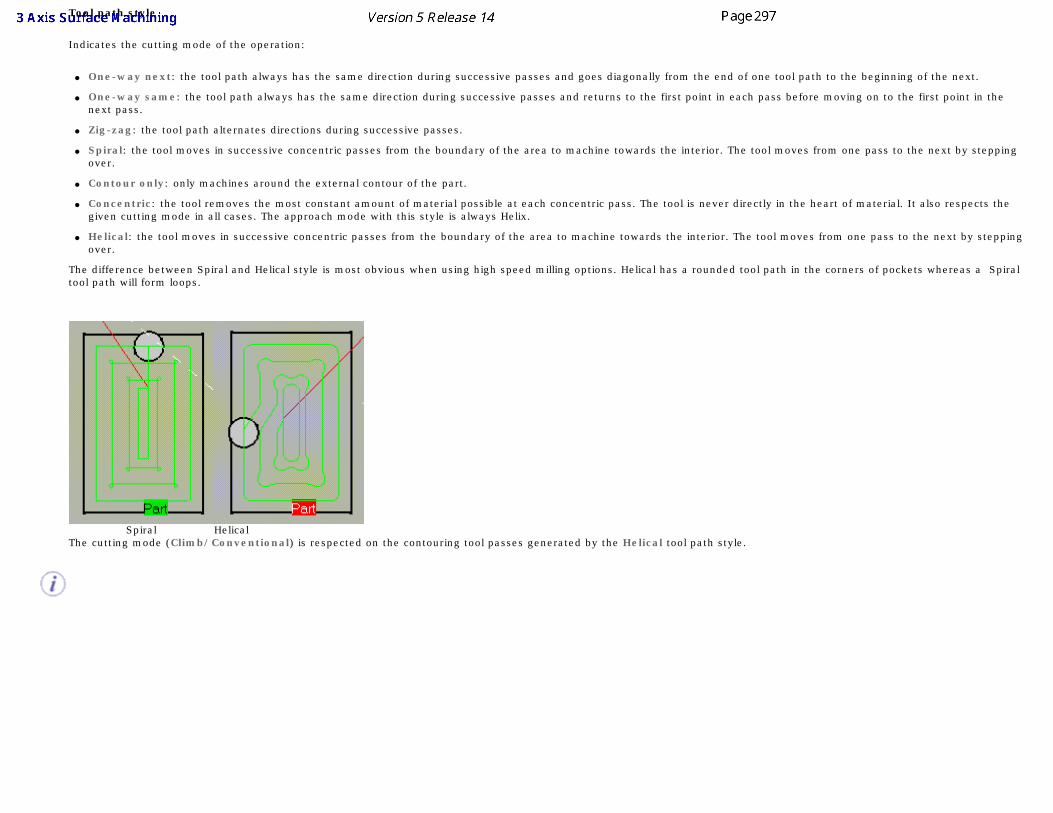
Tool path style
Indicates the cutting mode of the operation:
● One-way next: the tool path always has the same direction during successive passes and goes diagonally from the end of one tool path to the beginning of the next.
● One-way same: the tool path always has the same direction during successive passes and returns to the first point in each pass before moving on to the first point in the next pass.
● Zig-zag: the tool path alternates directions during successive passes.
● Spiral: the tool moves in successive concentric passes from the boundary of the area to machine towards the interior. The tool moves from one pass to the next by stepping over.
● Contour only: only machines around the external contour of the part.
● Concentric: the tool removes the most constant amount of material possible at each concentric pass. The tool is never directly in the heart of material. It also respects the given cutting mode in all cases. The approach mode with this style is always Helix.
● Helical: the tool moves in successive concentric passes from the boundary of the area to machine towards the interior. The tool moves from one pass to the next by stepping over.
The difference between Spiral and Helical style is most obvious when using high speed milling options. Helical has a rounded tool path in the corners of pockets whereas a Spiral tool path will form loops.
Spiral Helical The cutting mode (Climb/Conventional) is respected on the contouring tool passes generated by the Helical tool path style.
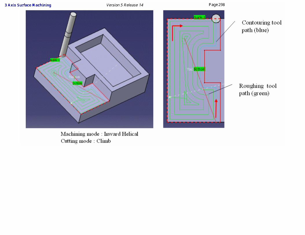
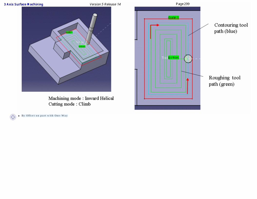
● By Offset on part with One-Way
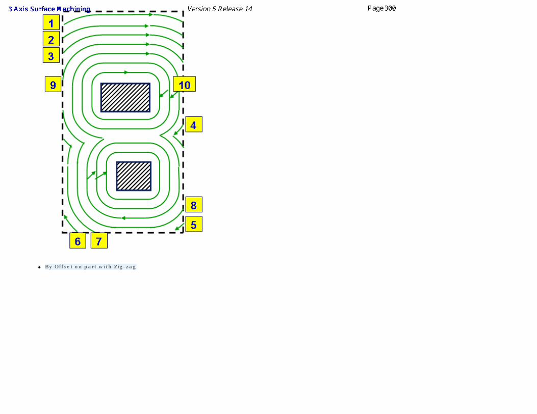
● By Offset on part with Zig-zag
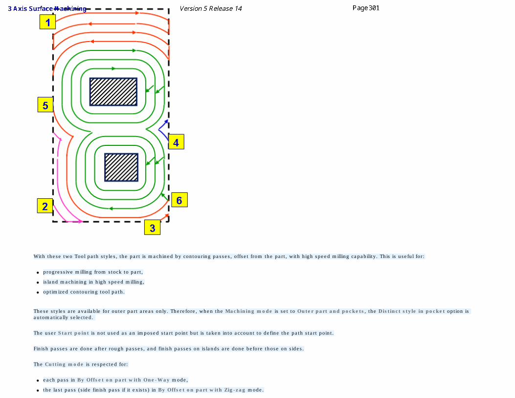
With these two Tool path styles, the part is machined by contouring passes, offset from the part, with high speed milling capability. This is useful for:
● progressive milling from stock to part,
● island machining in high speed milling,
● optimized contouring tool path.
These styles are available for outer part areas only. Therefore, when the Machining mode is set to Outer part and pockets, the Distinct style in pocket option is automatically selected.
The user Start point is not used as an imposed start point but is taken into account to define the path start point.
Finish passes are done after rough passes, and finish passes on islands are done before those on sides.
The Cutting mode is respected for:
● each pass in By Offset on part with One-Way mode,
● the last pass (side finish pass if it exists) in By Offset on part with Zig-zag mode.
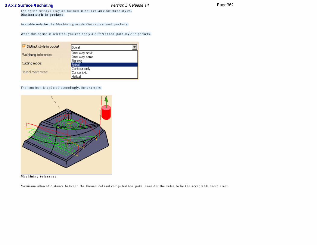
The option Always stay on bottom is not available for these styles. Distinct style in pockets
Available only for the Machining mode Outer part and pockets.
When this option is selected, you can apply a different tool path style to pockets.
The icon icon is updated accordingly, for example:
Machining tolerance
Maximum allowed distance between the theoretical and computed tool path. Consider the value to be the acceptable chord error.
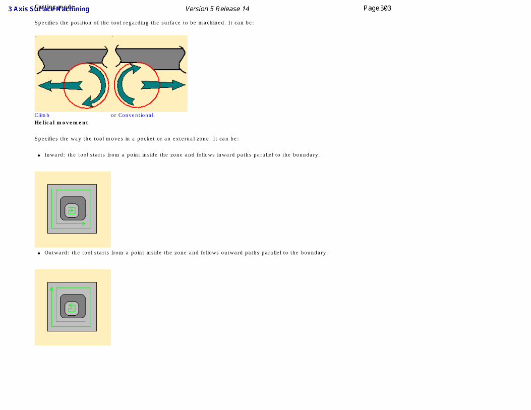
Cutting mode
Specifies the position of the tool regarding the surface to be machined. It can be:
Climb or Conventional.Helical movement
Specifies the way the tool moves in a pocket or an external zone. It can be:
● Inward: the tool starts from a point inside the zone and follows inward paths parallel to the boundary.
● Outward: the tool starts from a point inside the zone and follows outward paths parallel to the boundary.
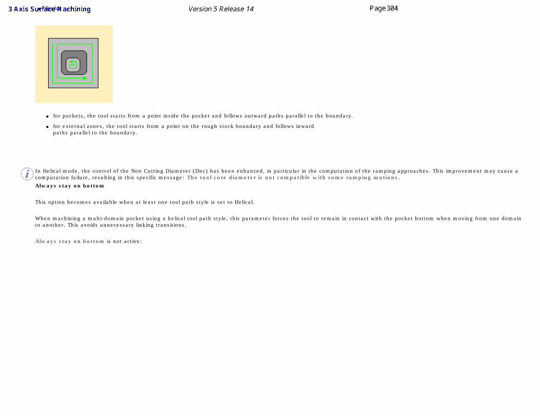
● Both:
● for pockets, the tool starts from a point inside the pocket and follows outward paths parallel to the boundary.
● for external zones, the tool starts from a point on the rough stock boundary and follows inward paths parallel to the boundary.
In Helical mode, the control of the Non Cutting Diameter (Dnc) has been enhanced, in particular in the computation of the ramping approaches. This improvement may cause a computation failure, resulting in this specific message: The tool core diameter is not compatible with some ramping motions.
Always stay on bottom
This option becomes available when at least one tool path style is set to Helical.
When machining a multi-domain pocket using a helical tool path style, this parameter forces the tool to remain in contact with the pocket bottom when moving from one domain to another. This avoids unnecessary linking transitions.
Always stay on bottom is not active:
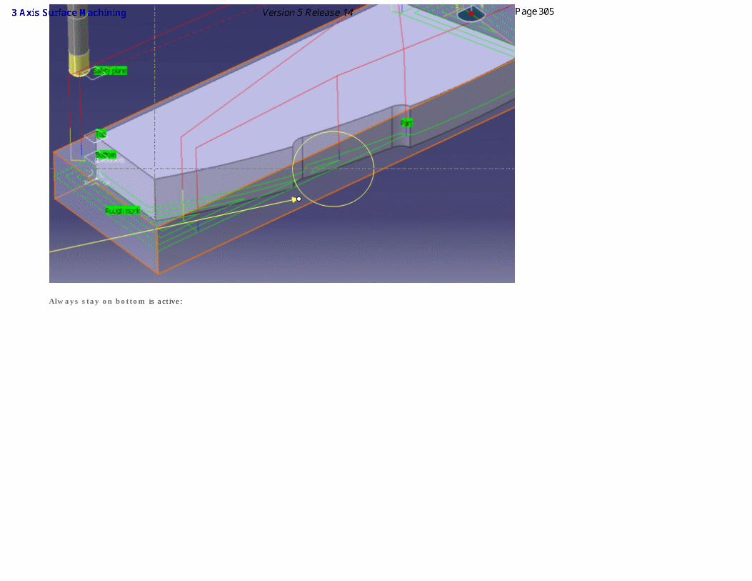
Always stay on bottom is active:
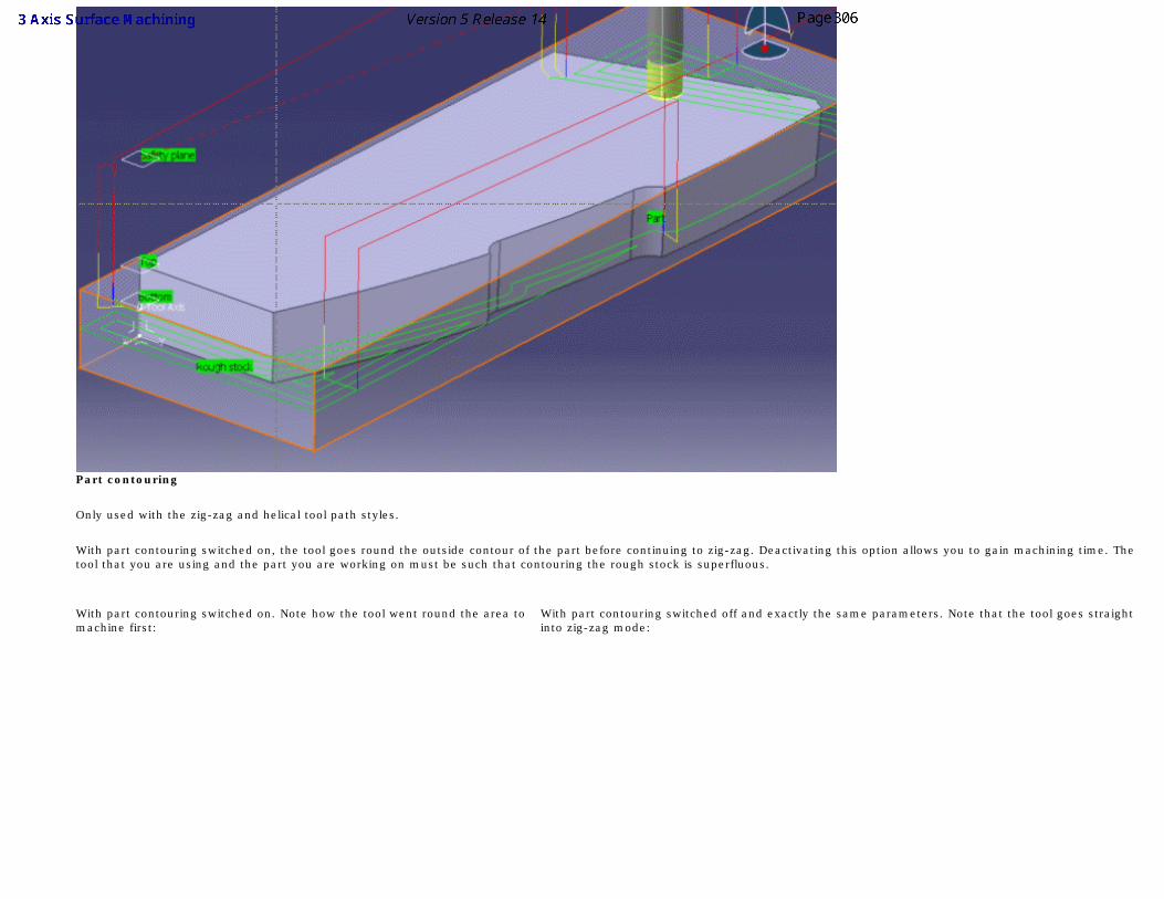
Part contouring
Only used with the zig-zag and helical tool path styles.
With part contouring switched on, the tool goes round the outside contour of the part before continuing to zig-zag. Deactivating this option allows you to gain machining time. The tool that you are using and the part you are working on must be such that contouring the rough stock is superfluous.
With part contouring switched on. Note how the tool went round the area to machine first:
With part contouring switched off and exactly the same parameters. Note that the tool goes straight into zig-zag mode:
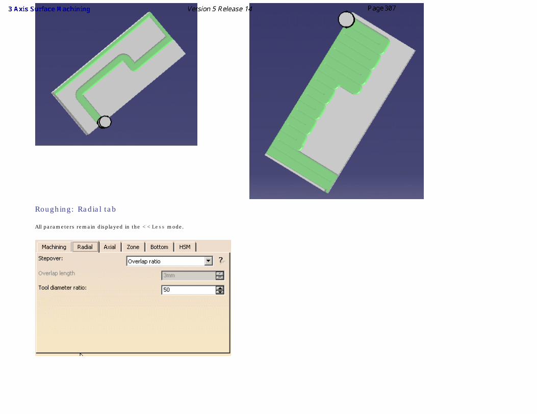
Roughing: Radial tab
All parameters remain displayed in the <<Less mode.
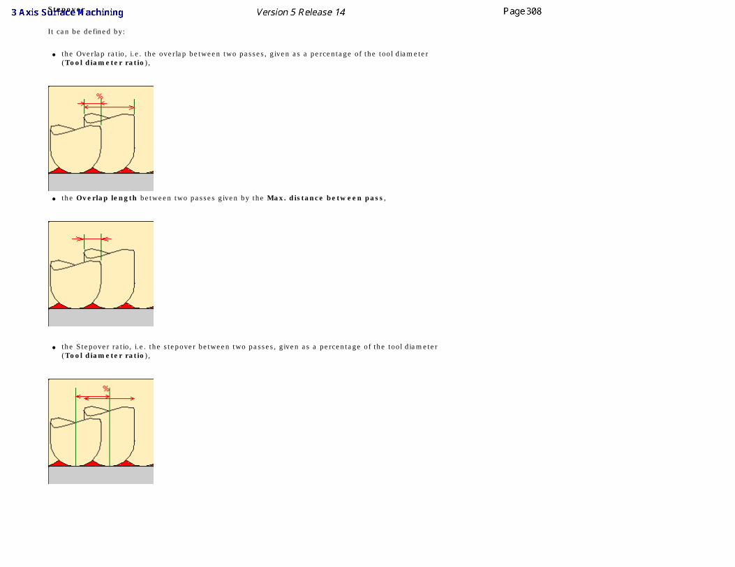
Stepover
It can be defined by:
● the Overlap ratio, i.e. the overlap between two passes, given as a percentage of the tool diameter (Tool diameter ratio),
● the Overlap length between two passes given by the Max. distance between pass,
● the Stepover ratio, i.e. the stepover between two passes, given as a percentage of the tool diameter(Tool diameter ratio),
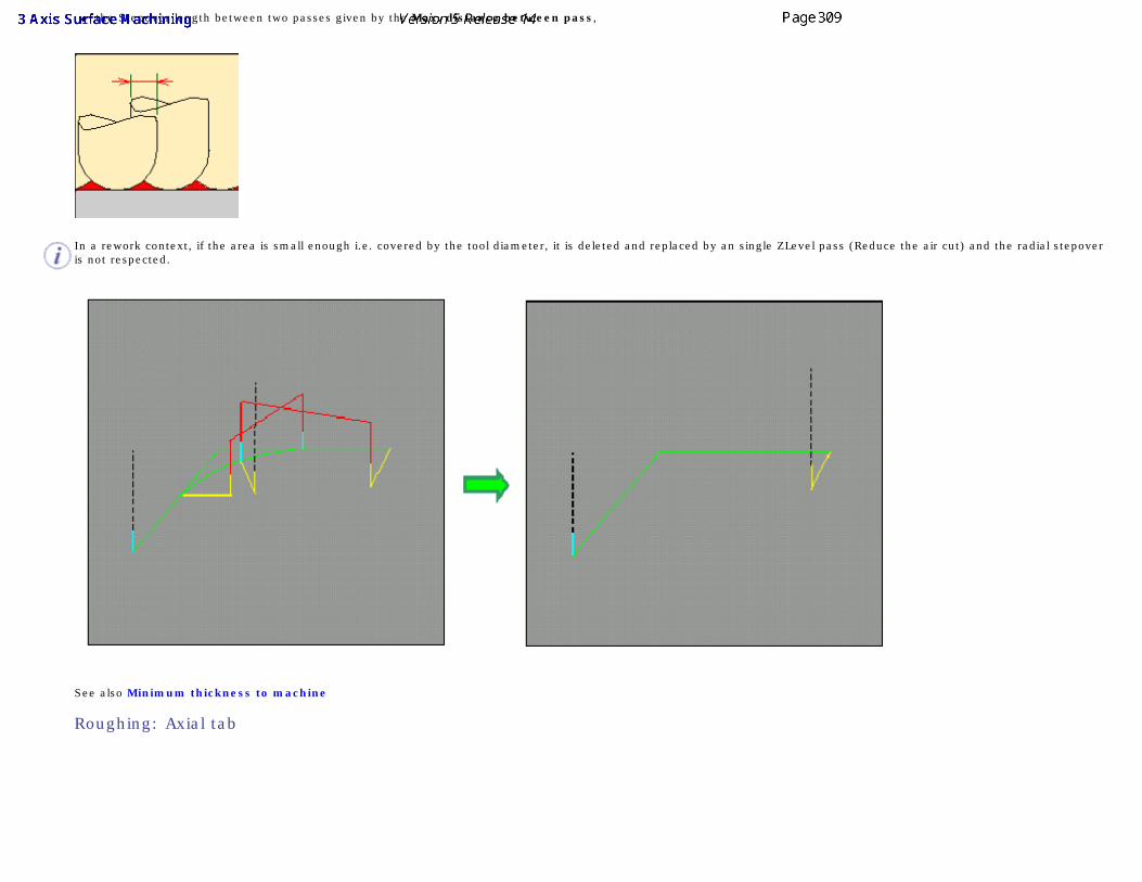
● the Stepover length between two passes given by the Max. distance between pass,
In a rework context, if the area is small enough i.e. covered by the tool diameter, it is deleted and replaced by an single ZLevel pass (Reduce the air cut) and the radial stepover is not respected.
See also Minimum thickness to machine
Roughing: Axial tab
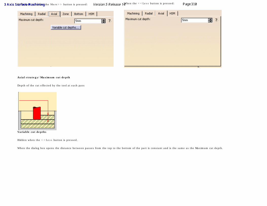
By default, or when the More>> button is pressed: When the <<Less button is pressed:
Axial strategy/Maximum cut depth
Depth of the cut effected by the tool at each pass
Variable cut depths
Hidden when the <<Less button is pressed.
When the dialog box opens the distance between passes from the top to the bottom of the part is constant and is the same as the Maximum cut depth.
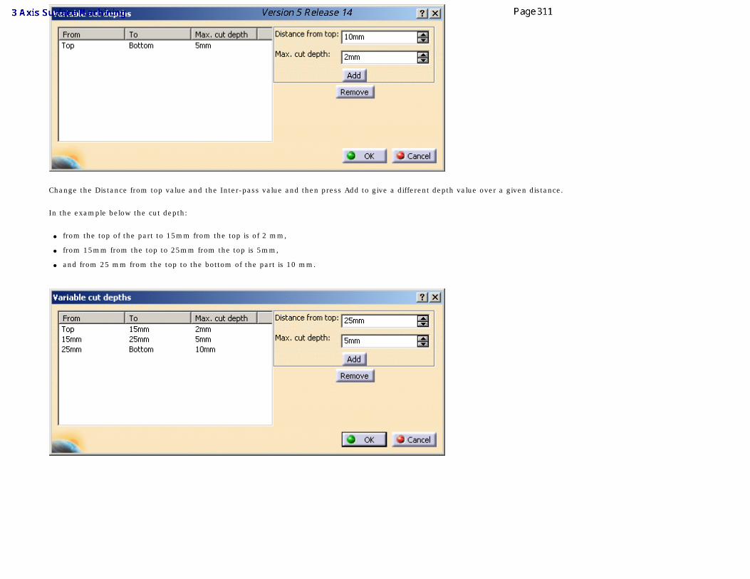
Change the Distance from top value and the Inter-pass value and then press Add to give a different depth value over a given distance.
In the example below the cut depth:
● from the top of the part to 15mm from the top is of 2 mm,
● from 15mm from the top to 25mm from the top is 5mm,
● and from 25 mm from the top to the bottom of the part is 10 mm.
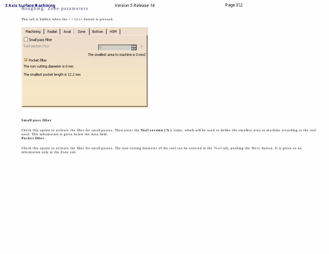
Roughing: Zone parameters
This tab is hidden when the <<Less button is pressed.
Small pass filter
Check this option to activate the filter for small passes. Then enter the Tool section (%) value, which will be used to define the smallest area to machine according to the tool used. This information is given below the data field.
Pocket filter
Check this option to activate the filter for small passes. The non-cutting diameter of the tool can be entered in the Tool tab, pushing the More button. It is given as an information only in the Zone tab.
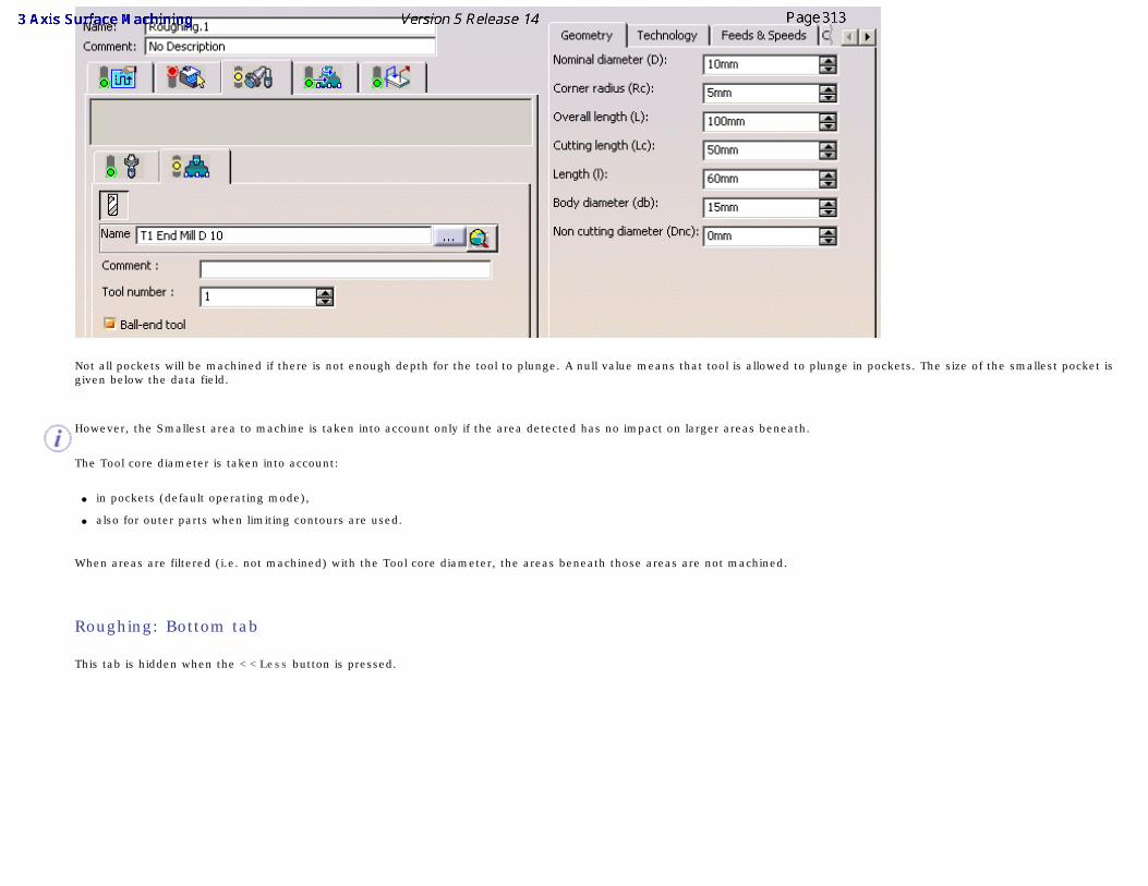
Not all pockets will be machined if there is not enough depth for the tool to plunge. A null value means that tool is allowed to plunge in pockets. The size of the smallest pocket is given below the data field.
However, the Smallest area to machine is taken into account only if the area detected has no impact on larger areas beneath.
The Tool core diameter is taken into account:
● in pockets (default operating mode),
● also for outer parts when limiting contours are used.
When areas are filtered (i.e. not machined) with the Tool core diameter, the areas beneath those areas are not machined.
Roughing: Bottom tab
This tab is hidden when the <<Less button is pressed.
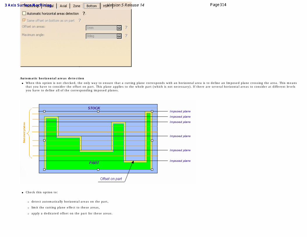
Automatic horizontal areas detection
● When this option is not checked, the only way to ensure that a cutting plane corresponds with an horizontal area is to define an Imposed plane crossing the area. This means that you have to consider the offset on part. This plane applies to the whole part (which is not necessary). If there are several horizontal areas to consider at different levels you have to define all of the corresponding imposed planes.
● Check this option to:
❍ detect automatically horizontal areas on the part,
❍ limit the cutting plane effect to these areas,
❍ apply a dedicated offset on the part for these areas.
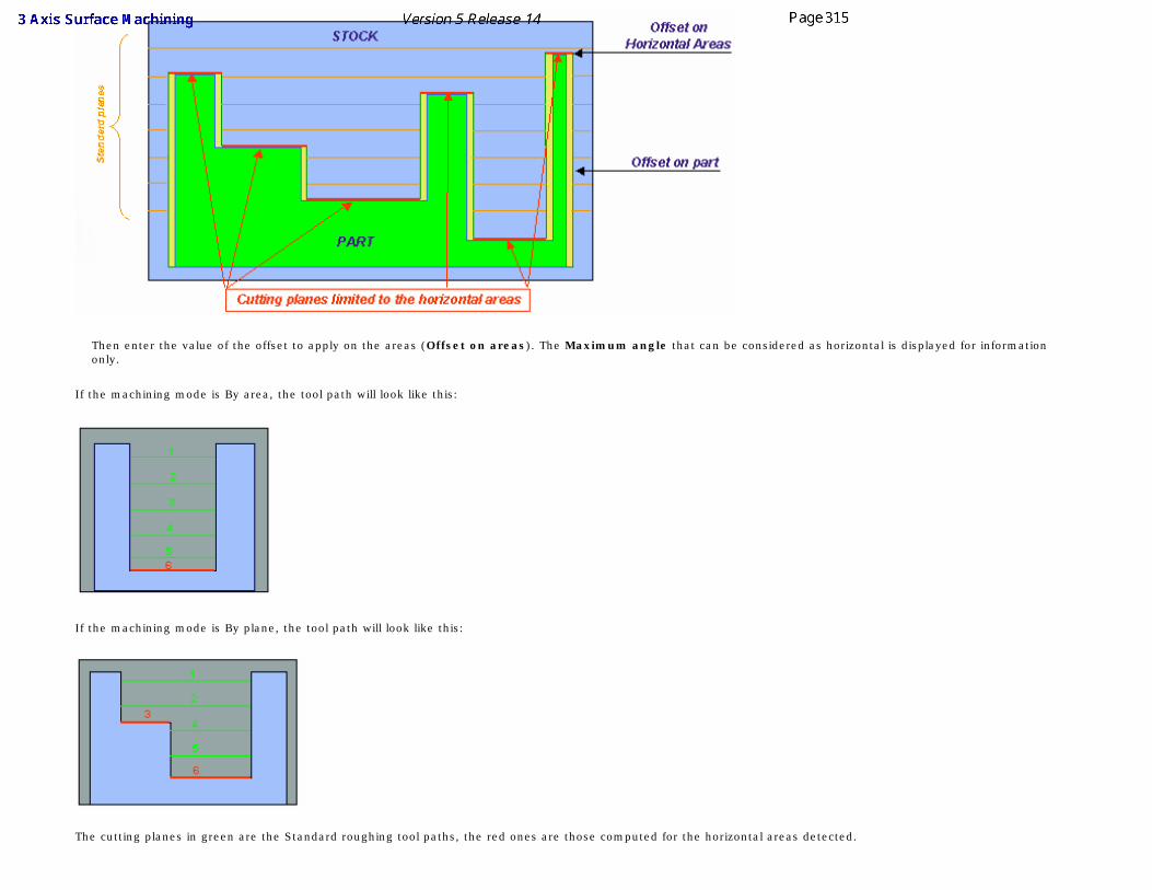
Then enter the value of the offset to apply on the areas (Offset on areas). The Maximum angle that can be considered as horizontal is displayed for information only.
If the machining mode is By area, the tool path will look like this:
If the machining mode is By plane, the tool path will look like this:
The cutting planes in green are the Standard roughing tool paths, the red ones are those computed for the horizontal areas detected.
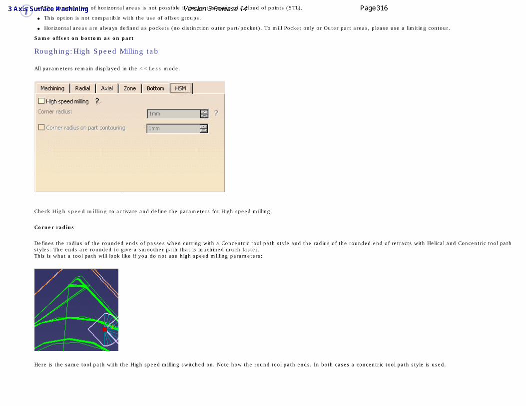
● The computation of horizontal areas is not possible if the part is made of a cloud of points (STL).
● This option is not compatible with the use of offset groups.
● Horizontal areas are always defined as pockets (no distinction outer part/pocket). To mill Pocket only or Outer part areas, please use a limiting contour.
Same offset on bottom as on part
Roughing:High Speed Milling tab
All parameters remain displayed in the <<Less mode.
Check High speed milling to activate and define the parameters for High speed milling.
Corner radius
Defines the radius of the rounded ends of passes when cutting with a Concentric tool path style and the radius of the rounded end of retracts with Helical and Concentric tool path styles. The ends are rounded to give a smoother path that is machined much faster.This is what a tool path will look like if you do not use high speed milling parameters:
Here is the same tool path with the High speed milling switched on. Note how the round tool path ends. In both cases a concentric tool path style is used.
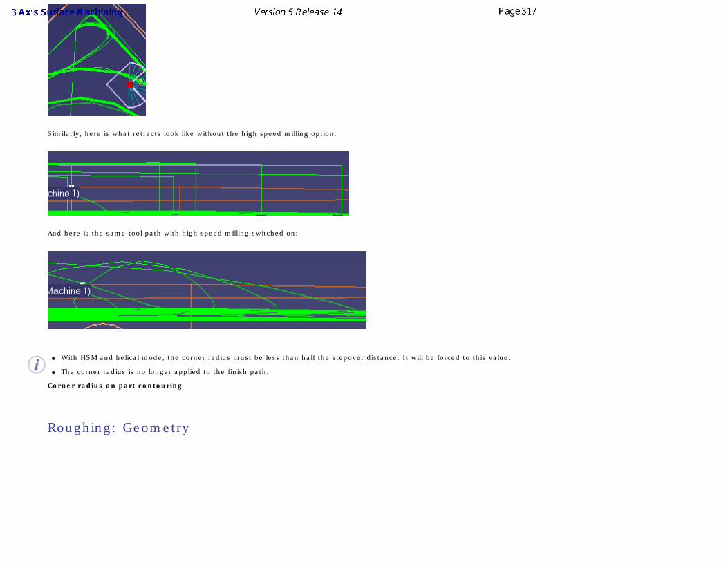
Similarly, here is what retracts look like without the high speed milling option:
And here is the same tool path with high speed milling switched on:
● With HSM and helical mode, the corner radius must be less than half the stepover distance. It will be forced to this value.
● The corner radius is no longer applied to the finish path.
Corner radius on part contouring
Roughing: Geometry
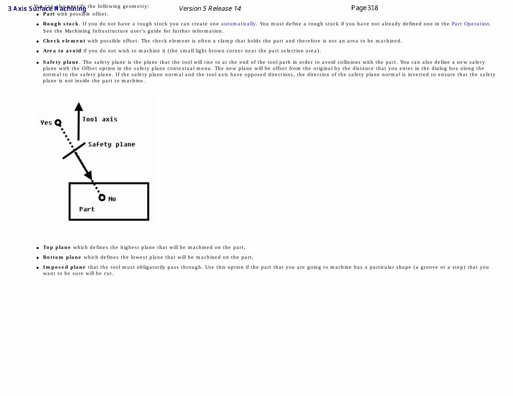
You can also specify the following geometry: ● Part with possible offset.
● Rough stock. If you do not have a rough stock you can create one automatically. You must define a rough stock if you have not already defined one in the Part Operation. See the Machining Infrastructure user's guide for further information.
● Check element with possible offset. The check element is often a clamp that holds the part and therefore is not an area to be machined.
● Area to avoid if you do not wish to machine it (the small light brown corner near the part selection area).
● Safety plane. The safety plane is the plane that the tool will rise to at the end of the tool path in order to avoid collisions with the part. You can also define a new safety plane with the Offset option in the safety plane contextual menu. The new plane will be offset from the original by the distance that you enter in the dialog box along the normal to the safety plane. If the safety plane normal and the tool axis have opposed directions, the direction of the safety plane normal is inverted to ensure that the safety plane is not inside the part to machine.
● Top plane which defines the highest plane that will be machined on the part,
● Bottom plane which defines the lowest plane that will be machined on the part,
● Imposed plane that the tool must obligatorily pass through. Use this option if the part that you are going to machine has a particular shape (a groove or a step) that you want to be sure will be cut.
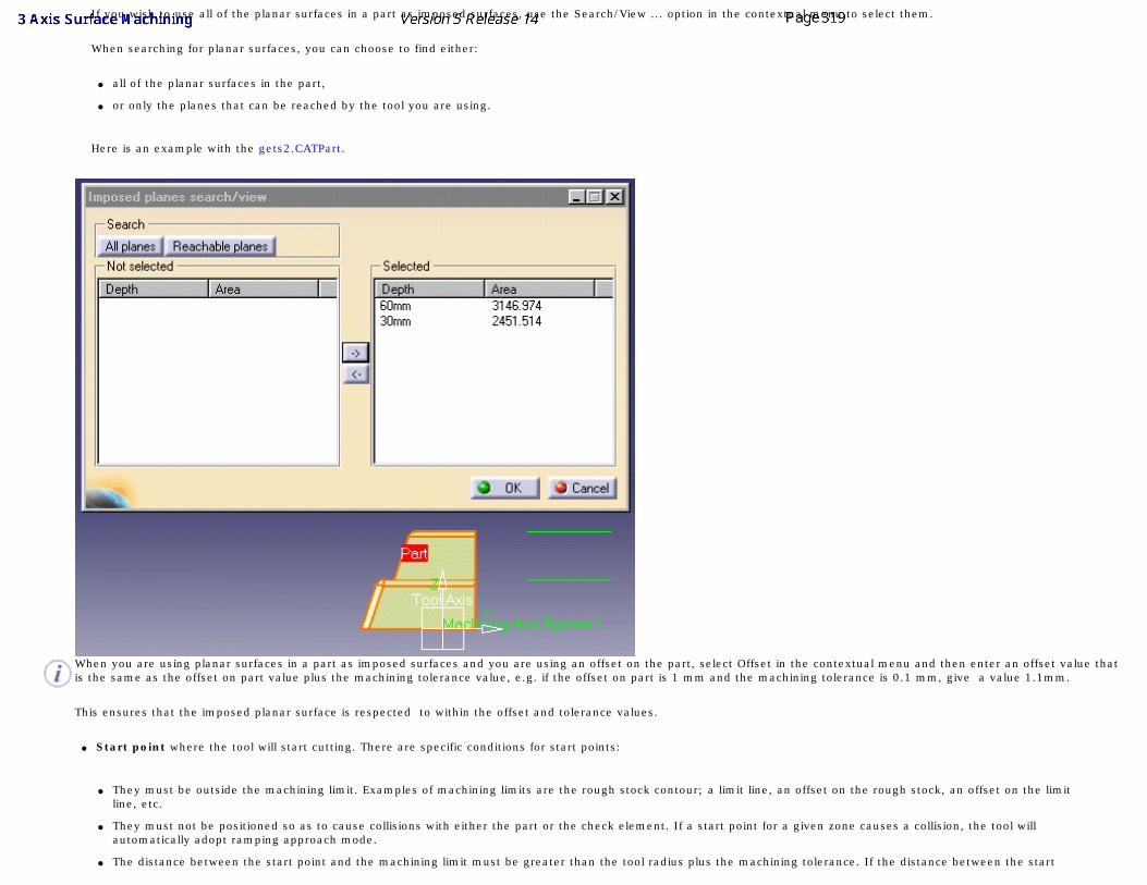
If you wish to use all of the planar surfaces in a part as imposed surfaces, use the Search/View ... option in the contextual menu to select them.
When searching for planar surfaces, you can choose to find either:
● all of the planar surfaces in the part,
● or only the planes that can be reached by the tool you are using.
Here is an example with the gets2.CATPart.
When you are using planar surfaces in a part as imposed surfaces and you are using an offset on the part, select Offset in the contextual menu and then enter an offset value that is the same as the offset on part value plus the machining tolerance value, e.g. if the offset on part is 1 mm and the machining tolerance is 0.1 mm, give a value 1.1mm.
This ensures that the imposed planar surface is respected to within the offset and tolerance values.
● Start point where the tool will start cutting. There are specific conditions for start points:
● They must be outside the machining limit. Examples of machining limits are the rough stock contour; a limit line, an offset on the rough stock, an offset on the limit line, etc.
● They must not be positioned so as to cause collisions with either the part or the check element. If a start point for a given zone causes a collision, the tool will automatically adopt ramping approach mode.
● The distance between the start point and the machining limit must be greater than the tool radius plus the machining tolerance. If the distance between the start
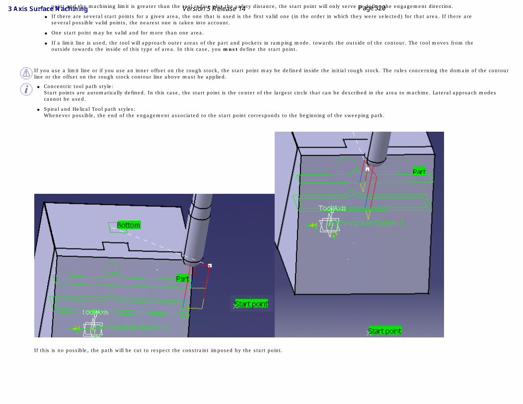
point and the machining limit is greater than the tool radius plus the safety distance, the start point will only serve to define the engagement direction.
● If there are several start points for a given area, the one that is used is the first valid one (in the order in which they were selected) for that area. If there are several possible valid points, the nearest one is taken into account.
● One start point may be valid and for more than one area.
● If a limit line is used, the tool will approach outer areas of the part and pockets in ramping mode. towards the outside of the contour. The tool moves from the outside towards the inside of this type of area. In this case, you must define the start point.
If you use a limit line or if you use an inner offset on the rough stock, the start point may be defined inside the initial rough stock. The rules concerning the domain of the contour line or the offset on the rough stock contour line above must be applied.
● Concentric tool path style: Start points are automatically defined. In this case, the start point is the center of the largest circle that can be described in the area to machine. Lateral approach modes cannot be used.
● Spiral and Helical Tool path styles: Whenever possible, the end of the engagement associated to the start point corresponds to the beginning of the sweeping path.
If this is no possible, the path will be cut to respect the constraint imposed by the start point.
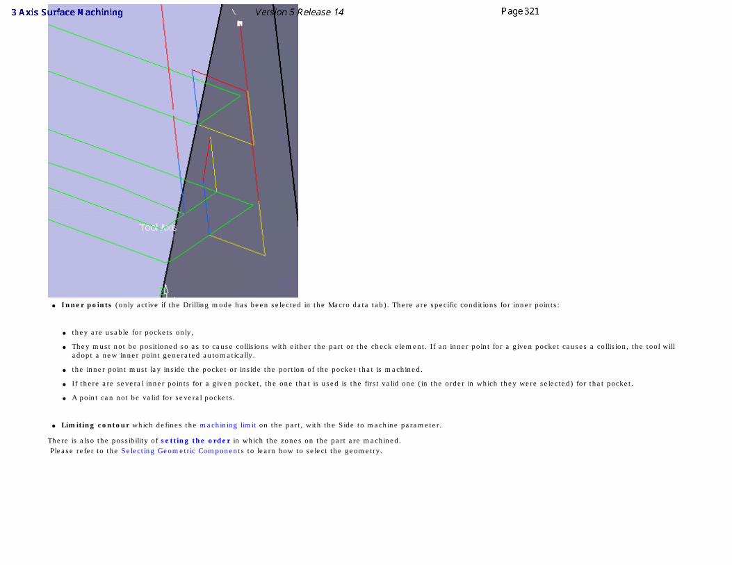
● Inner points (only active if the Drilling mode has been selected in the Macro data tab). There are specific conditions for inner points:
● they are usable for pockets only,
● They must not be positioned so as to cause collisions with either the part or the check element. If an inner point for a given pocket causes a collision, the tool will adopt a new inner point generated automatically.
● the inner point must lay inside the pocket or inside the portion of the pocket that is machined.
● If there are several inner points for a given pocket, the one that is used is the first valid one (in the order in which they were selected) for that pocket.
● A point can not be valid for several pockets.
● Limiting contour which defines the machining limit on the part, with the Side to machine parameter.
There is also the possibility of setting the order in which the zones on the part are machined. Please refer to the Selecting Geometric Components to learn how to select the geometry.
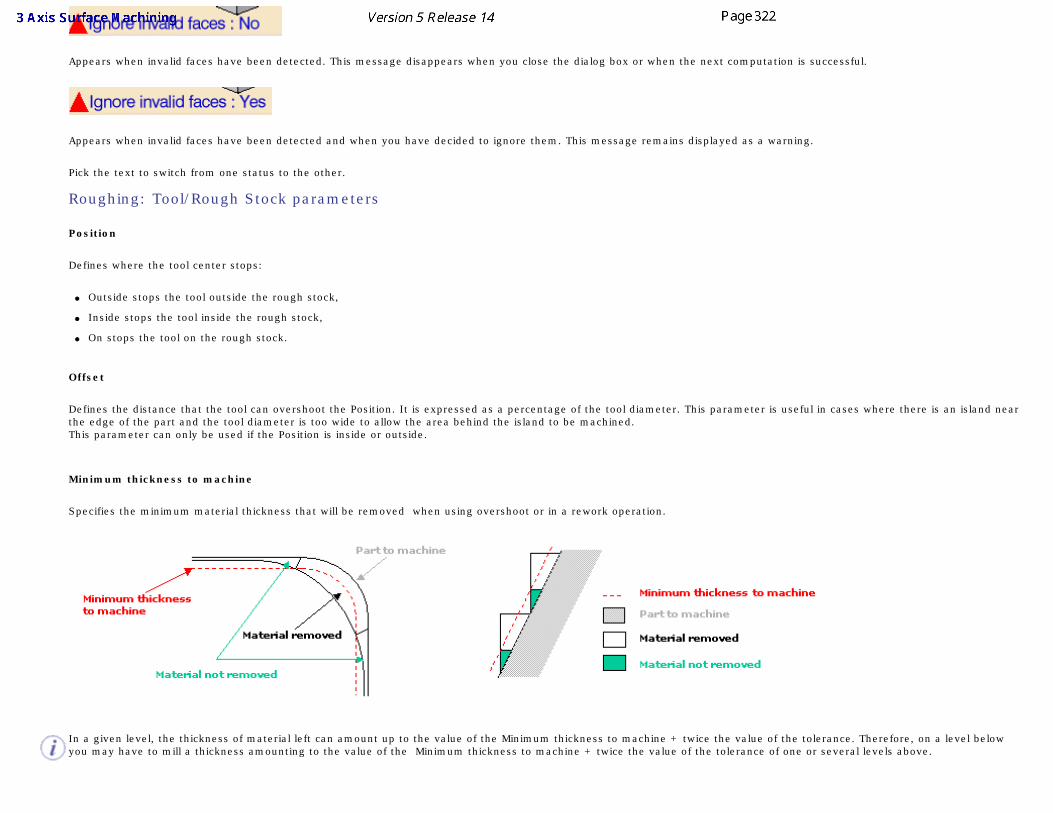
Appears when invalid faces have been detected. This message disappears when you close the dialog box or when the next computation is successful.
Appears when invalid faces have been detected and when you have decided to ignore them. This message remains displayed as a warning.
Pick the text to switch from one status to the other.
Roughing: Tool/Rough Stock parameters
Position
Defines where the tool center stops:
● Outside stops the tool outside the rough stock,
● Inside stops the tool inside the rough stock,
● On stops the tool on the rough stock.
Offset
Defines the distance that the tool can overshoot the Position. It is expressed as a percentage of the tool diameter. This parameter is useful in cases where there is an island near the edge of the part and the tool diameter is too wide to allow the area behind the island to be machined. This parameter can only be used if the Position is inside or outside.
Minimum thickness to machine
Specifies the minimum material thickness that will be removed when using overshoot or in a rework operation.
In a given level, the thickness of material left can amount up to the value of the Minimum thickness to machine + twice the value of the tolerance. Therefore, on a level below you may have to mill a thickness amounting to the value of the Minimum thickness to machine + twice the value of the tolerance of one or several levels above.
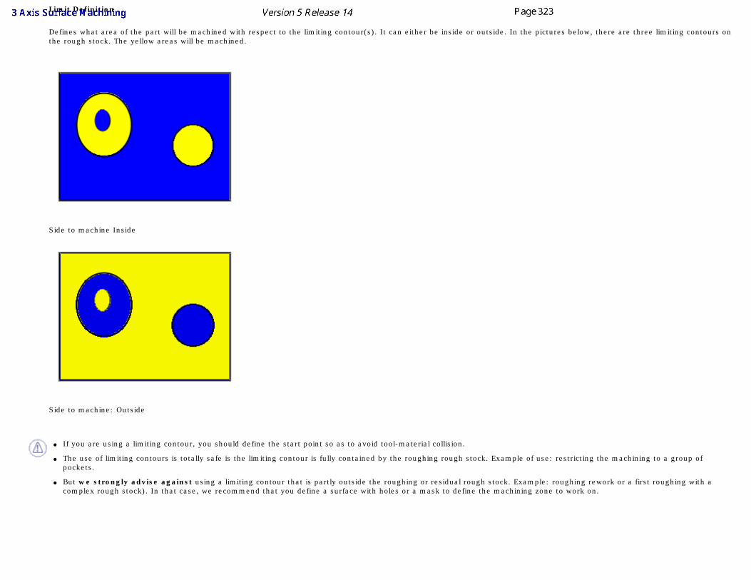
Limit Definition
Defines what area of the part will be machined with respect to the limiting contour(s). It can either be inside or outside. In the pictures below, there are three limiting contours on the rough stock. The yellow areas will be machined.
Side to machine Inside
Side to machine: Outside
● If you are using a limiting contour, you should define the start point so as to avoid tool-material collision.
● The use of limiting contours is totally safe is the limiting contour is fully contained by the roughing rough stock. Example of use: restricting the machining to a group of pockets.
● But we strongly advise against using a limiting contour that is partly outside the roughing or residual rough stock. Example: roughing rework or a first roughing with a complex rough stock). In that case, we recommend that you define a surface with holes or a mask to define the machining zone to work on.
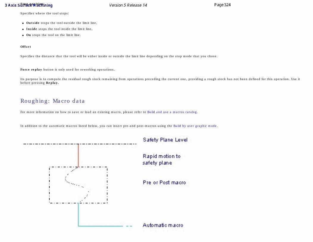
Stop position
Specifies where the tool stops:
● Outside stops the tool outside the limit line,
● Inside stops the tool inside the limit line,
● On stops the tool on the limit line.
Offset
Specifies the distance that the tool will be either inside or outside the limit line depending on the stop mode that you chose.
Force replay button is only used for reworking operations.
Its purpose is to compute the residual rough stock remaining from operations preceding the current one, providing a rough stock has not been defined for this operation. Use it before pressing Replay.
Roughing: Macro data
For more information on how to save or load an existing macro, please refer to Build and use a macros catalog.
In addition to the automatic macros listed below, you can insert pre-and post-macros using the Build by user graphic mode.
If the last motion of the pre- or post-macro is above the safety plane level, there will be no rapid motion to the safety plane.
Optimize retract
This button optimizes tool retract movements. This means that when the tool moves over a surface where there are no obstructions, it will not rise as high as the safety plane because there is no danger of tool-part collisions. The result is a gain in time.
● The parameter Optimize Retract takes the rough stock left by the previous operation into account.
● If you have defined a safety plane, you should deactivate the Optimize retracts option. If you do not, the safety plane will be ignored.
●
Axial safety distance
Maximum distance that the tool will rise to when moving from the end of one pass to the beginning of the next.
Mode
Specifies the engagement of the tool in the material:
● Plunge; the tool plunges vertically,
● Drilling; the tool plunges into previously drilled holes. You can change the Drilling tool diameter, Drilling tool angle and Drilling tool length,
● Ramping; the tool moves progressively down at the Ramping angle,
● Helix; the tool moves progressively down at the ramping angle with its center along a (vertical) circular helix of Helix diameter.
Those four approach modes apply to pockets.
● If the Tool Path is Concentric, the approach is always Helix, either on outer areas or pockets.
● Ramping approach mode applies to pockets but also outer areas in given conditions:
● If a limit line is used, the tool will approach outer areas of the part and pockets in ramping mode.
● If a lateral approach is not possible (due to the check element), the approach is made in ramping mode.
Approach distance
Engagement distance for plunge mode.
Radial safety distance
Distance that the tool moves horizontally before it begins its approach.
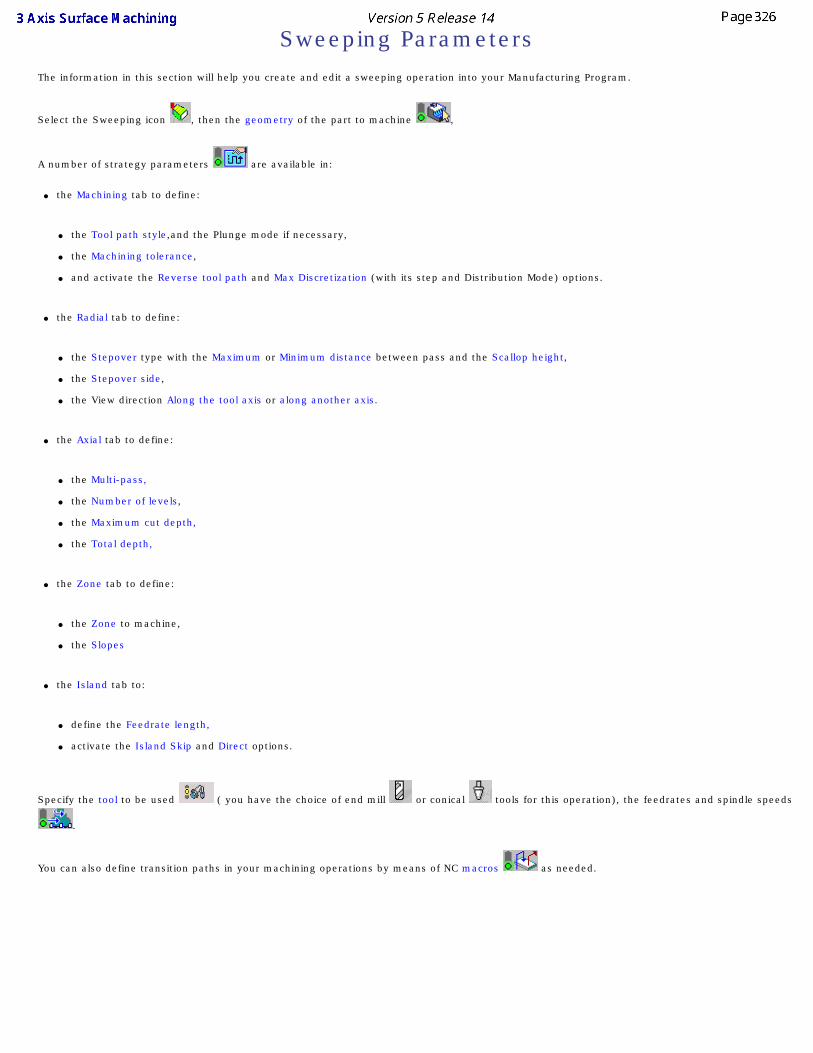
Sweeping ParametersThe information in this section will help you create and edit a sweeping operation into your Manufacturing Program.
Select the Sweeping icon , then the geometry of the part to machine ,
A number of strategy parameters are available in:
● the Machining tab to define:
● the Tool path style,and the Plunge mode if necessary,
● the Machining tolerance,
● and activate the Reverse tool path and Max Discretization (with its step and Distribution Mode) options.
● the Radial tab to define:
● the Stepover type with the Maximum or Minimum distance between pass and the Scallop height,
● the Stepover side,
● the View direction Along the tool axis or along another axis.
● the Axial tab to define:
● the Multi-pass,
● the Number of levels,
● the Maximum cut depth,
● the Total depth,
● the Zone tab to define:
● the Zone to machine,
● the Slopes
● the Island tab to:
● define the Feedrate length,
● activate the Island Skip and Direct options.
Specify the tool to be used ( you have the choice of end mill or conical tools for this operation), the feedrates and spindle speeds
.
You can also define transition paths in your machining operations by means of NC macros as needed.
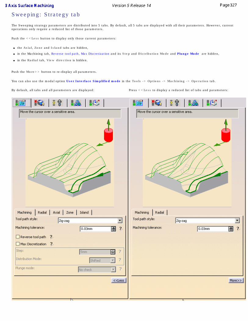
Sweeping: Strategy tab
The Sweeping strategy parameters are distributed into 5 tabs. By default, all 5 tabs are displayed with all their parameters. However, current operations only require a reduced list of those parameters.
Push the <<Less button to display only those current parameters:
● the Axial, Zone and Island tabs are hidden,
● in the Machining tab, Reverse tool path, Max Discretization and its Step and Distribution Mode and Plunge Mode are hidden,
● in the Radial tab, View direction is hidden.
Push the More>> button to re-display all parameters.
You can also use the modal option User Interface Simplified mode in the Tools -> Options -> Machining -> Operation tab. By default, all tabs and all parameters are displayed: Press <<Less to display a reduced list of tabs and parameters:
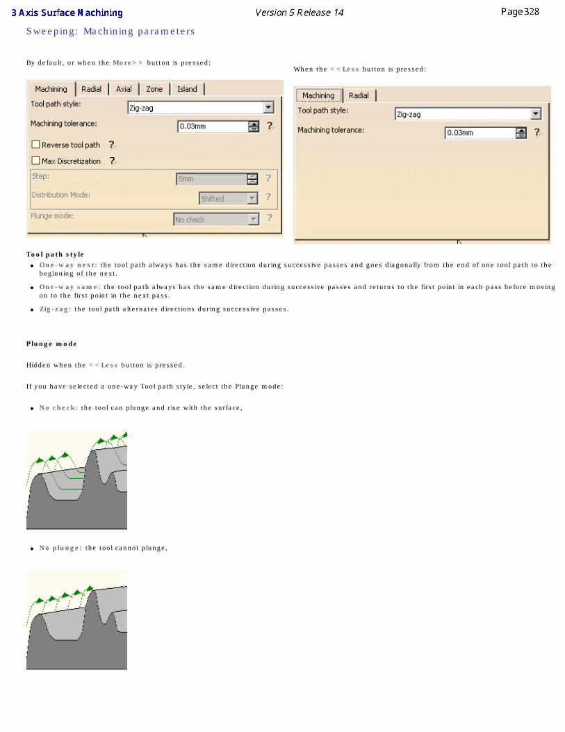
Sweeping: Machining parameters
By default, or when the More>> button is pressed:
When the <<Less button is pressed:
Tool path style ● One-way next: the tool path always has the same direction during successive passes and goes diagonally from the end of one tool path to the
beginning of the next.
● One-way same: the tool path always has the same direction during successive passes and returns to the first point in each pass before moving on to the first point in the next pass.
● Zig-zag: the tool path alternates directions during successive passes.
Plunge mode
Hidden when the <<Less button is pressed.
If you have selected a one-way Tool path style, select the Plunge mode:
● No check: the tool can plunge and rise with the surface,
● No plunge: the tool cannot plunge,
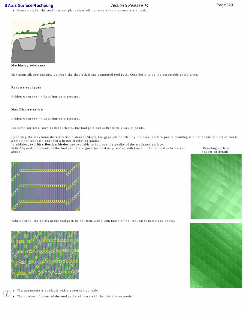
● Same height: the tool does not plunge but will not stop when it encounters a peak.
Machining tolerance
Maximum allowed distance between the theoretical and computed tool path. Consider it to be the acceptable chord error.
Reverse tool path
Hidden when the <<Less button is pressed.
Max Discretization
Hidden when the <<Less button is pressed.
For some surfaces, such as flat surfaces, the tool path can suffer from a lack of points.
By setting the maximum discretization distance (Step), the gaps will be filled by the exact surface points resulting in a better distribution of points, a smoother tool path and then a better machining quality.
In addition, two Distribution Modes are available to improve the quality of the machined surface.With Aligned, the points of the tool path are aligned (as best as possible) with those of the tool paths below and above.
Resulting surface(Zoom on details)
With Shifted, the points of the tool path do not form a line with those of the tool paths below and above.
● This parameter is available with a spherical tool only.
● The number of points of the tool paths will vary with the distribution mode.
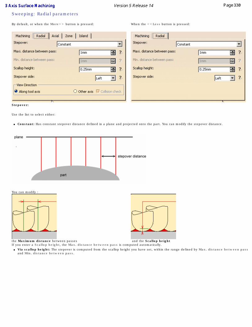
Sweeping: Radial parameters
By default, or when the More>> button is pressed: When the <<Less button is pressed:
Stepover:
Use the list to select either:
● Constant: Has constant stepover distance defined in a plane and projected onto the part. You can modify the stepover distance.
You can modify :
the Maximum distance between passes and the Scallop height If you enter a Scallop height, the Max. distance between pass is computed automatically.
● Via scallop height: The stepover is computed from the scallop height you have set, within the range defined by Max. distance between pass and Min. distance between pass.
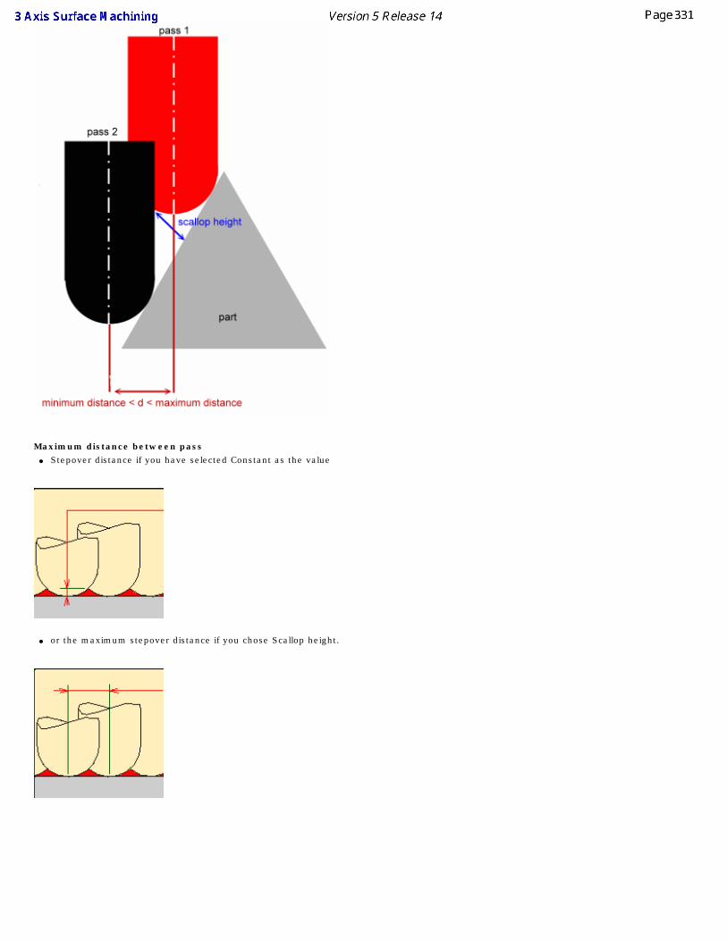
Maximum distance between pass
● Stepover distance if you have selected Constant as the value
● or the maximum stepover distance if you chose Scallop height.
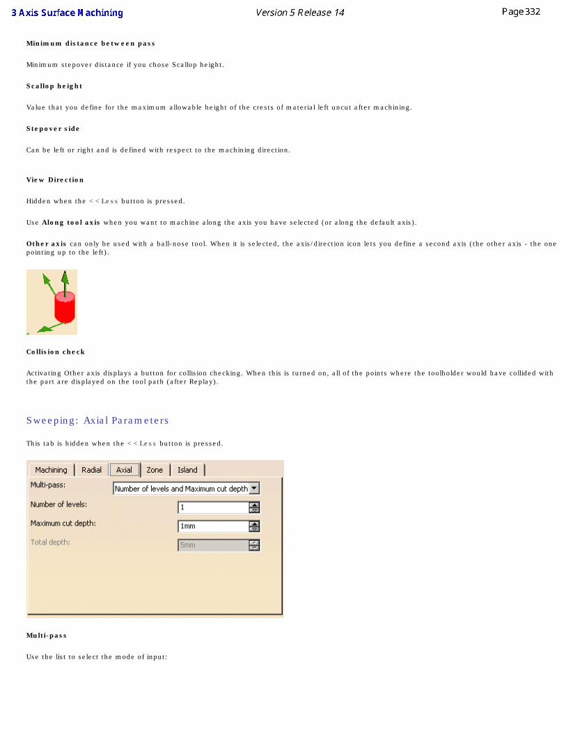
Minimum distance between pass
Minimum stepover distance if you chose Scallop height.
Scallop height
Value that you define for the maximum allowable height of the crests of material left uncut after machining.
Stepover side
Can be left or right and is defined with respect to the machining direction.
View Direction
Hidden when the <<Less button is pressed.
Use Along tool axis when you want to machine along the axis you have selected (or along the default axis).
Other axis can only be used with a ball-nose tool. When it is selected, the axis/direction icon lets you define a second axis (the other axis - the one pointing up to the left).
Collision check
Activating Other axis displays a button for collision checking. When this is turned on, all of the points where the toolholder would have collided with the part are displayed on the tool path (after Replay).
Sweeping: Axial Parameters
This tab is hidden when the <<Less button is pressed.
Multi-pass
Use the list to select the mode of input:
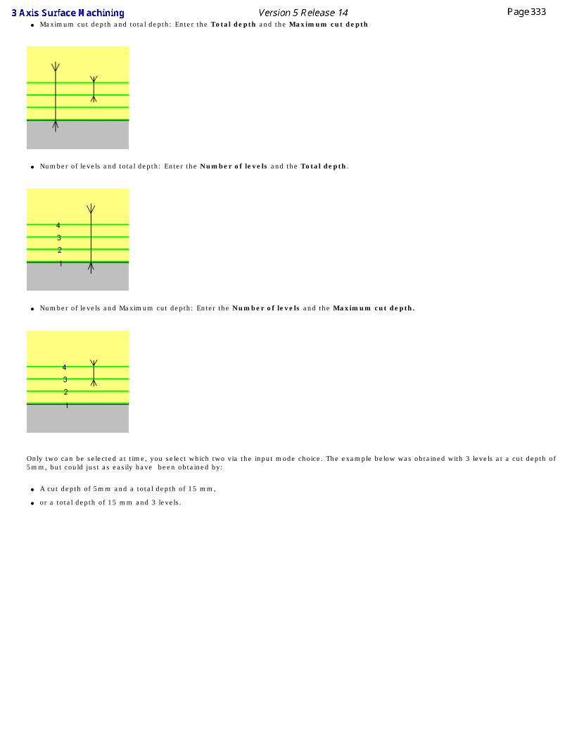
● Maximum cut depth and total depth: Enter the Total depth and the Maximum cut depth
● Number of levels and total depth: Enter the Number of levels and the Total depth.
● Number of levels and Maximum cut depth: Enter the Number of levels and the Maximum cut depth.
Only two can be selected at time, you select which two via the input mode choice. The example below was obtained with 3 levels at a cut depth of 5mm, but could just as easily have been obtained by:
● A cut depth of 5mm and a total depth of 15 mm,
● or a total depth of 15 mm and 3 levels.
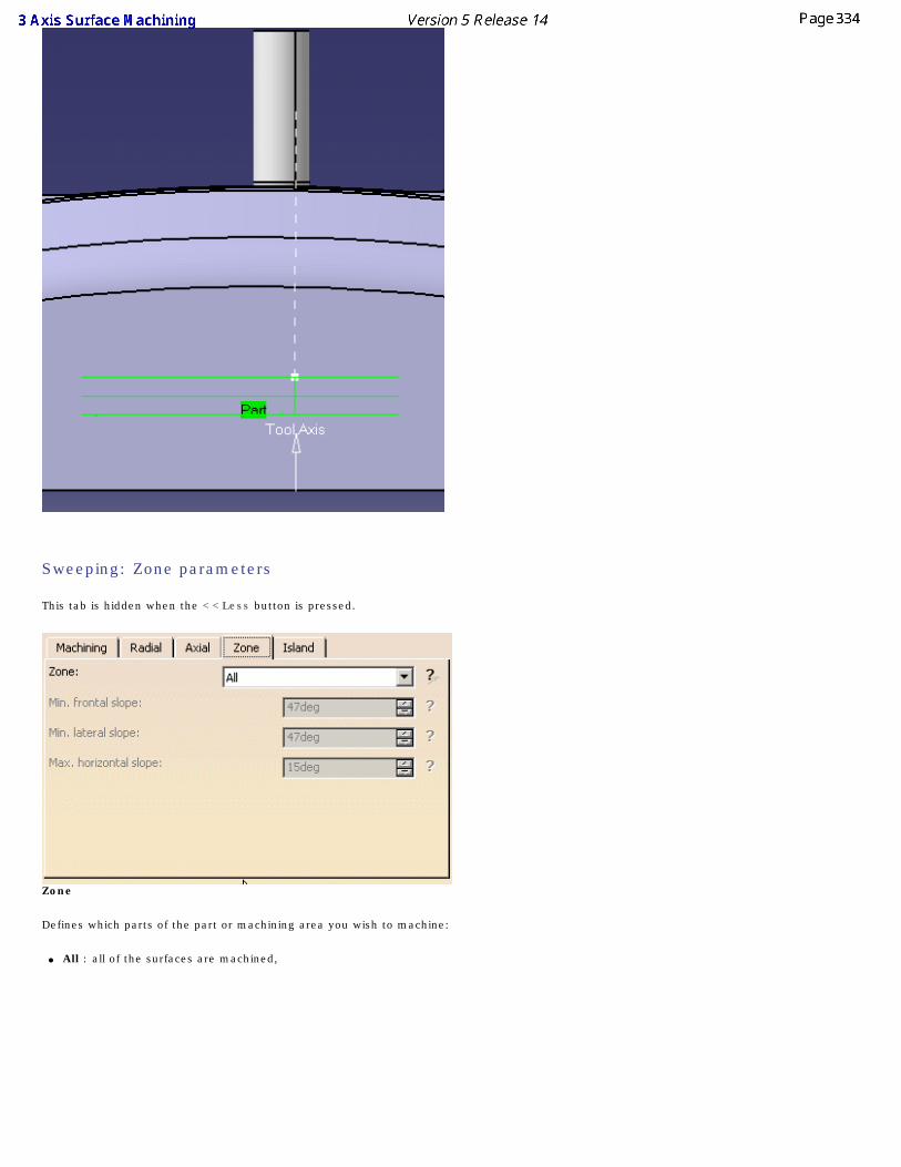
Sweeping: Zone parameters
This tab is hidden when the <<Less button is pressed.
Zone
Defines which parts of the part or machining area you wish to machine:
● All : all of the surfaces are machined,
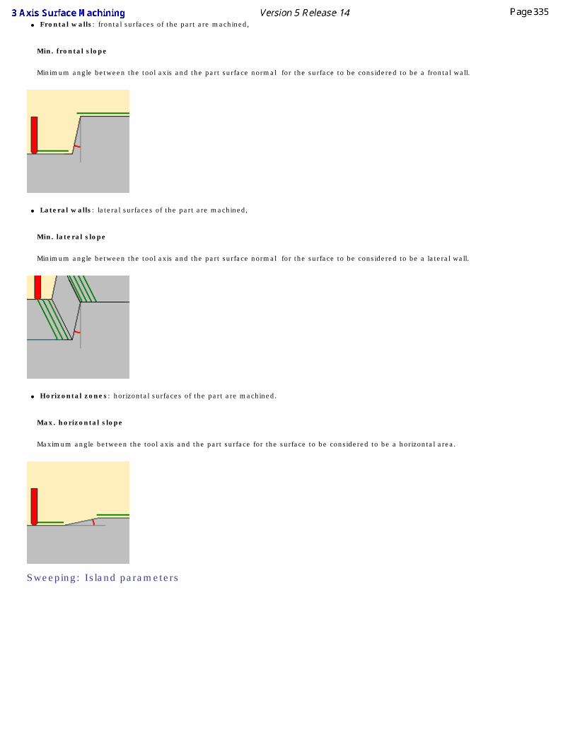
● Frontal walls: frontal surfaces of the part are machined,
Min. frontal slope
Minimum angle between the tool axis and the part surface normal for the surface to be considered to be a frontal wall.
● Lateral walls: lateral surfaces of the part are machined,
Min. lateral slope
Minimum angle between the tool axis and the part surface normal for the surface to be considered to be a lateral wall.
● Horizontal zones: horizontal surfaces of the part are machined.
Max. horizontal slope
Maximum angle between the tool axis and the part surface for the surface to be considered to be a horizontal area.
Sweeping: Island parameters
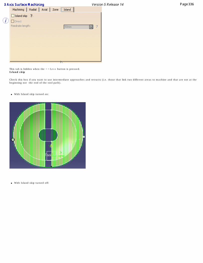
This tab is hidden when the <<Less button is pressed.Island skip
Check this box if you want to use intermediate approaches and retracts (i.e. those that link two different areas to machine and that are not at the beginning nor the end of the tool path).
● With Island skip turned on:
● With Island skip turned off:
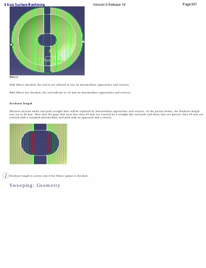
Direct
With Direct checked, the tool is not allowed to rise on intermediate approaches and retracts.
Whit Direct not checked, the tool will rise to 10 mm on intermediate approaches and retracts.
Feedrate length
Distance beyond which tool path straight lines will be replaced by intermediate approaches and retracts. In the picture below, the Feedrate length was set to 45 mm. Note that the gaps that were less than 45 mm are crossed by a straight line tool path and those that are greater than 45 mm are crossed with a standard intermediate tool path with an approach and a retract.
Feedrate length is active only if the Direct option is checked.
Sweeping: Geometry
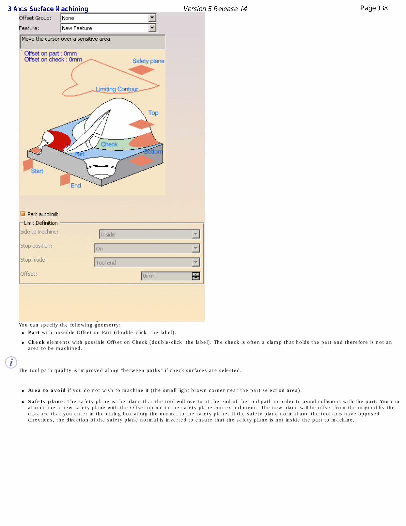
You can specify the following geometry: ● Part with possible Offset on Part (double-click the label).
● Check elements with possible Offset on Check (double-click the label). The check is often a clamp that holds the part and therefore is not an area to be machined.
The tool path quality is improved along "between paths" if check surfaces are selected.
● Area to avoid if you do not wish to machine it (the small light brown corner near the part selection area).
● Safety plane. The safety plane is the plane that the tool will rise to at the end of the tool path in order to avoid collisions with the part. You can
also define a new safety plane with the Offset option in the safety plane contextual menu. The new plane will be offset from the original by the distance that you enter in the dialog box along the normal to the safety plane. If the safety plane normal and the tool axis have opposed directions, the direction of the safety plane normal is inverted to ensure that the safety plane is not inside the part to machine.
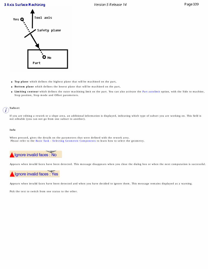
● Top plane which defines the highest plane that will be machined on the part,
● Bottom plane which defines the lowest plane that will be machined on the part,
● Limiting contour which defines the outer machining limit on the part. You can also activate the Part autolimit option, with the Side to machine, Stop position, Stop mode and Offset parameters.
Subset
If you are editing a rework or a slope area, an additional information is displayed, indicating which type of subset you are working on. This field is not editable (you can not go from one subset to another).
Info
When pressed, gives the details on the parameters that were defined with the rework area. Please refer to the Basic Task - Selecting Geometric Components to learn how to select the geometry.
Appears when invalid faces have been detected. This message disappears when you close the dialog box or when the next computation is successful.
Appears when invalid faces have been detected and when you have decided to ignore them. This message remains displayed as a warning.
Pick the text to switch from one status to the other.
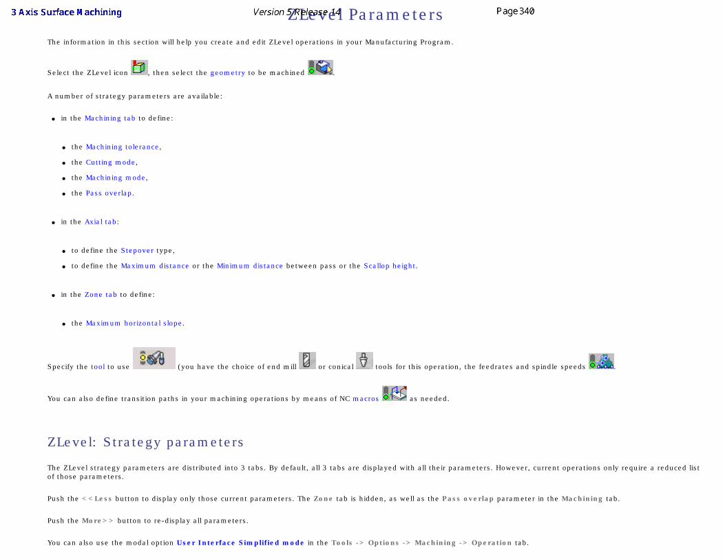
ZLevel ParametersThe information in this section will help you create and edit ZLevel operations in your Manufacturing Program.
Select the ZLevel icon , then select the geometry to be machined .
A number of strategy parameters are available:
● in the Machining tab to define:
● the Machining tolerance,
● the Cutting mode,
● the Machining mode,
● the Pass overlap.
● in the Axial tab:
● to define the Stepover type,
● to define the Maximum distance or the Minimum distance between pass or the Scallop height.
● in the Zone tab to define:
● the Maximum horizontal slope.
Specify the tool to use (you have the choice of end mill or conical tools for this operation, the feedrates and spindle speeds .
You can also define transition paths in your machining operations by means of NC macros as needed.
ZLevel: Strategy parameters
The ZLevel strategy parameters are distributed into 3 tabs. By default, all 3 tabs are displayed with all their parameters. However, current operations only require a reduced list of those parameters.
Push the <<Less button to display only those current parameters. The Zone tab is hidden, as well as the Pass overlap parameter in the Machining tab.
Push the More>> button to re-display all parameters.
You can also use the modal option User Interface Simplified mode in the Tools -> Options -> Machining -> Operation tab.
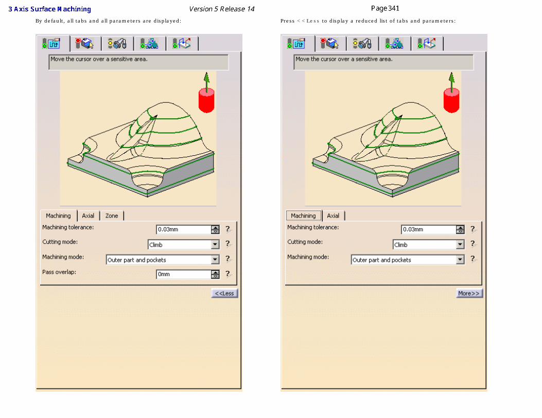
By default, all tabs and all parameters are displayed: Press <<Less to display a reduced list of tabs and parameters:
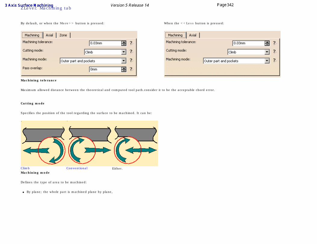
ZLevel: Machining tab
By default, or when the More>> button is pressed: When the <<Less button is pressed:
Machining tolerance
Maximum allowed distance between the theoretical and computed tool path.consider it to be the acceptable chord error.
Cutting mode
Specifies the position of the tool regarding the surface to be machined. It can be:
Climb Conventional Either.Machining mode
Defines the type of area to be machined:
● By plane; the whole part is machined plane by plane,
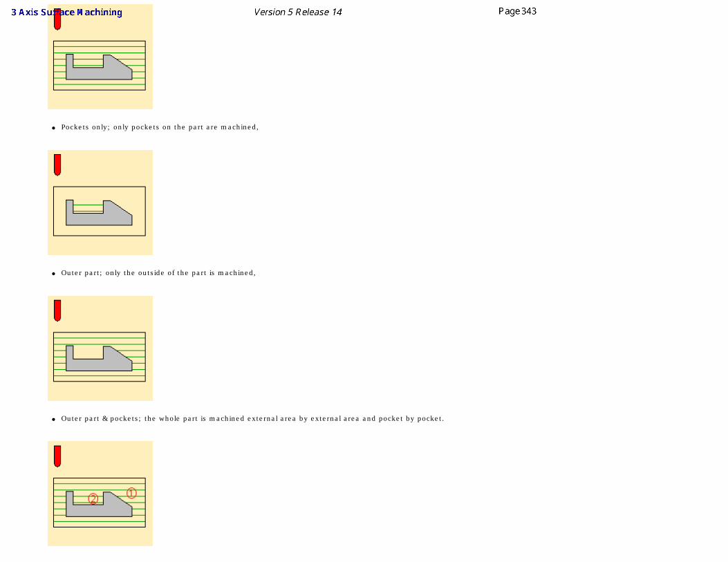
● Pockets only; only pockets on the part are machined,
● Outer part; only the outside of the part is machined,
● Outer part & pockets; the whole part is machined external area by external area and pocket by pocket.
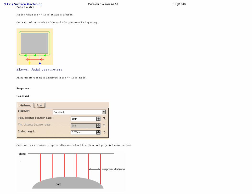
Pass overlap
Hidden when the <<Less button is pressed.
the width of the overlap of the end of a pass over its beginning.
ZLevel: Axial parameters
All parameters remain displayed in the <<Less mode.
Stepover
Constant
Constant has a constant stepover distance defined in a plane and projected onto the part.
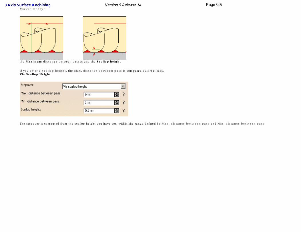
You can modify :
the Maximum distance between passes and the Scallop height
If you enter a Scallop height, the Max. distance between pass is computed automatically.Via Scallop Height
The stepover is computed from the scallop height you have set, within the range defined by Max. distance between pass and Min. distance between pass.
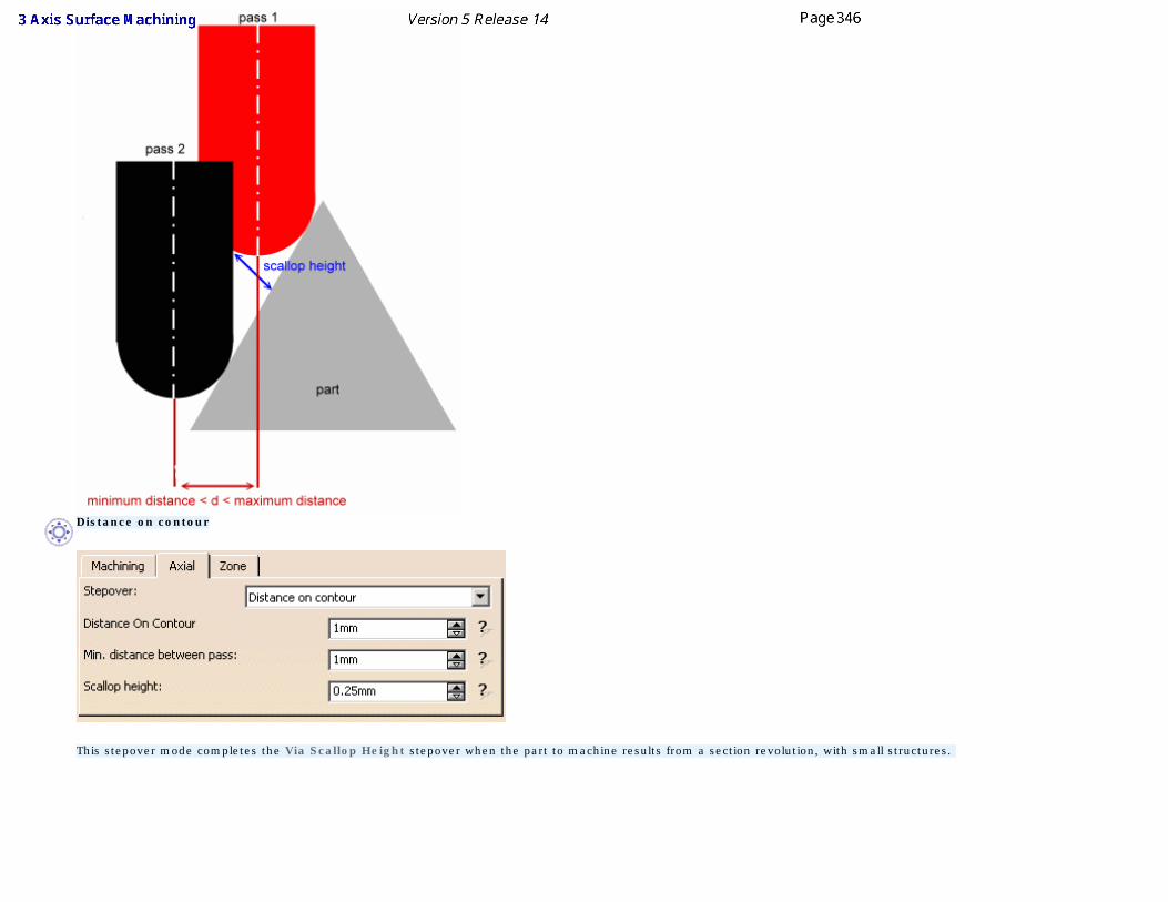
Distance on contour
This stepover mode completes the Via Scallop Height stepover when the part to machine results from a section revolution, with small structures.
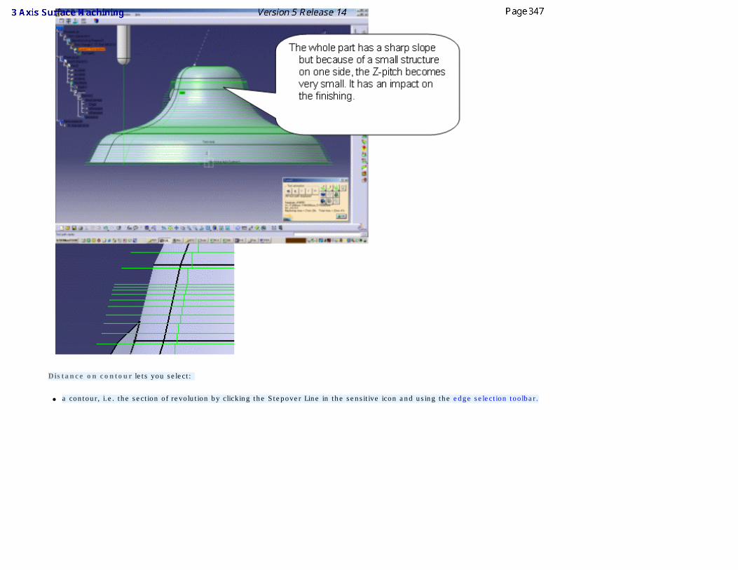
Distance on contour lets you select:
● a contour, i.e. the section of revolution by clicking the Stepover Line in the sensitive icon and using the edge selection toolbar.
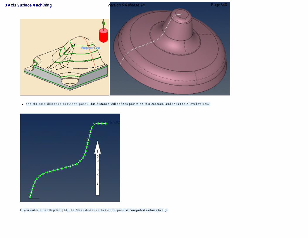
● and the Max distance between pass. This distance will defines points on this contour, and thus the Z level values.
If you enter a Scallop height, the Max. distance between pass is computed automatically.
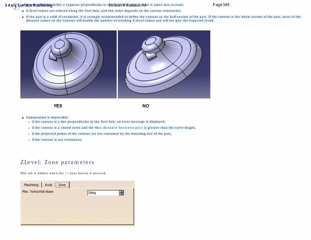
● if several points define a segment perpendicular to the Tool Axis, only 1 point is taken into account.
● Z-level values are ordered along the Tool Axis, and this order depends on the contour orientation.
● If the part is a solid of revolution, it is strongly recommended to define the contour as the half-section of the part. If the contour is the whole section of the part, most of the distance values on the Contour will double the number of resulting Z-level values and will not give the expected result.
● Computation is impossible:❍ if the contour is a line perpendicular to the Tool Axis, an error message is displayed,
❍ if the contour is a closed curve and the Max distance between pass is greater than the curve length,
❍ if the projected points of the contour are not contained by the bounding box of the part,
❍ if the contour is not continuous.
ZLevel: Zone parameters
This tab is hidden when the <<Less button is pressed.
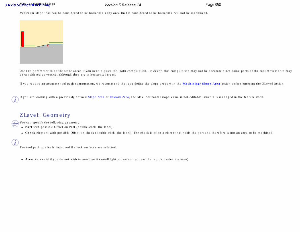
Max. horizontal slope
Maximum slope that can be considered to be horizontal (any area that is considered to be horizontal will not be machined).
Use this parameter to define slope areas if you need a quick tool path computation. However, this computation may not be accurate since some parts of the tool movements may be considered as vertical although they are in horizontal areas.
If you require an accurate tool path computation, we recommend that you define the slope areas with the Machining/Slope Area action before entering the ZLevel action.
If you are working with a previously defined Slope Area or Rework Area, the Max. horizontal slope value is not editable, since it is managed in the feature itself.
ZLevel: Geometry
You can specify the following geometry: ● Part with possible Offset on Part (double-click the label)
● Check element with possible Offset on check (double-click the label). The check is often a clamp that holds the part and therefore is not an area to be machined.
The tool path quality is improved if check surfaces are selected.
● Area to avoid if you do not wish to machine it (small light brown corner near the red part selection area).
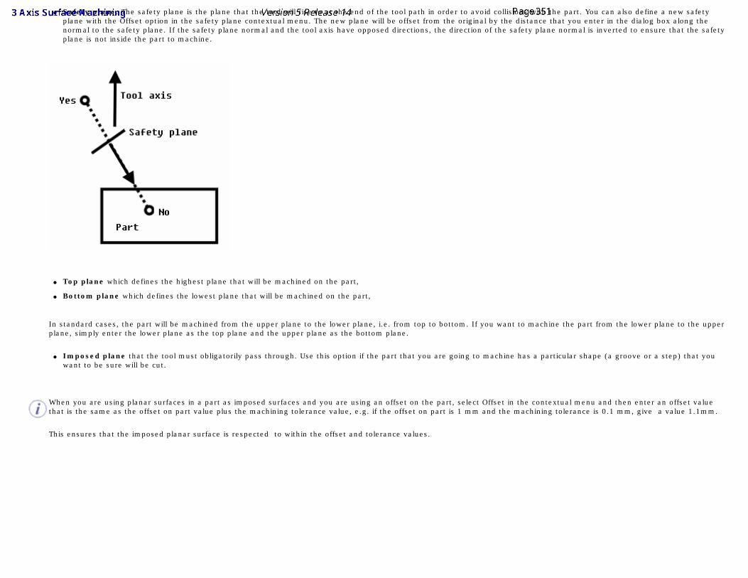
● Safety plane. The safety plane is the plane that the tool will rise to at the end of the tool path in order to avoid collisions with the part. You can also define a new safety
plane with the Offset option in the safety plane contextual menu. The new plane will be offset from the original by the distance that you enter in the dialog box along the normal to the safety plane. If the safety plane normal and the tool axis have opposed directions, the direction of the safety plane normal is inverted to ensure that the safety plane is not inside the part to machine.
● Top plane which defines the highest plane that will be machined on the part,
● Bottom plane which defines the lowest plane that will be machined on the part,
In standard cases, the part will be machined from the upper plane to the lower plane, i.e. from top to bottom. If you want to machine the part from the lower plane to the upper plane, simply enter the lower plane as the top plane and the upper plane as the bottom plane.
● Imposed plane that the tool must obligatorily pass through. Use this option if the part that you are going to machine has a particular shape (a groove or a step) that you want to be sure will be cut.
When you are using planar surfaces in a part as imposed surfaces and you are using an offset on the part, select Offset in the contextual menu and then enter an offset value that is the same as the offset on part value plus the machining tolerance value, e.g. if the offset on part is 1 mm and the machining tolerance is 0.1 mm, give a value 1.1mm.
This ensures that the imposed planar surface is respected to within the offset and tolerance values.
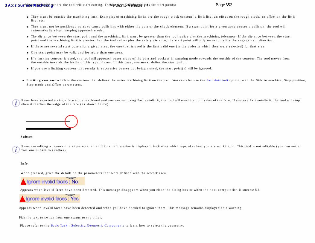
● Start point(s) where the tool will start cutting. There are specific conditions for start points:
● They must be outside the machining limit. Examples of machining limits are the rough stock contour; a limit line, an offset on the rough stock, an offset on the limit line, etc.
● They must not be positioned so as to cause collisions with either the part or the check element. If a start point for a given zone causes a collision, the tool will automatically adopt ramping approach mode.
● The distance between the start point and the machining limit must be greater than the tool radius plus the machining tolerance. If the distance between the start point and the machining limit is greater than the tool radius plus the safety distance, the start point will only serve to define the engagement direction.
● If there are several start points for a given area, the one that is used is the first valid one (in the order in which they were selected) for that area.
● One start point may be valid and for more than one area.
● If a limiting contour is used, the tool will approach outer areas of the part and pockets in ramping mode towards the outside of the contour. The tool moves from the outside towards the inside of this type of area. In this case, you must define the start point.
● If you use a limiting contour that results in successive passes not being closed, the start point(s) will be ignored.
● Limiting contour which is the contour that defines the outer machining limit on the part. You can also use the Part Autolimit option, with the Side to machine, Stop position, Stop mode and Offset parameters.
If you have selected a single face to be machined and you are not using Part autolimit, the tool will machine both sides of the face. If you use Part autolimit, the tool will stop when it reaches the edge of the face (as shown below).
Subset
If you are editing a rework or a slope area, an additional information is displayed, indicating which type of subset you are working on. This field is not editable (you can not go from one subset to another).
Info
When pressed, gives the details on the parameters that were defined with the rework area.
Appears when invalid faces have been detected. This message disappears when you close the dialog box or when the next computation is successful.
Appears when invalid faces have been detected and when you have decided to ignore them. This message remains displayed as a warning.
Pick the text to switch from one status to the other.
Please refer to the Basic Task - Selecting Geometric Components to learn how to select the geometry.
Spiral Milling Parameters
The information in this section will help you create and edit Spiral milling operations in your Manufacturing Program.
Select the Spiral milling icon , then select the geometry to be machined .
A number of strategy parameters are available:
● Horizontal zone selection,
● in the Machining tab to define:
● the Machining tolerance,
● the Cutting mode,
● the Offset on contour,
● the Helical movement,
● or activate the Reverse tool path option.
● in the Radial tab:
● to define the Max. distance between pass,
● to activate the Along tool axis or Other axis option.
● in the Axial tab to define:
● the Multi-pass parameters,
● the Number of levels,
● the Maximum cut depth,
● the Total depth,
● the Sequencing.
● in the Zone tab to define the Max. frontal slope,
● in the HSM tab:
● to activate the High speed milling,
● to define the Corner radius.
Specify the tool to use (the tools that can be used with this type of operation are end mill tools , conical tools , face mill tools
,and T-slotters ), the feedrates and spindle speeds ,
You can also define transition paths in your machining operations by means of NC macros as needed.
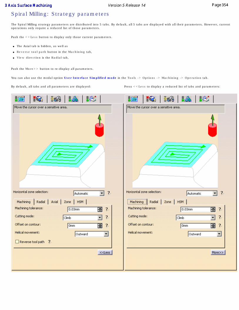
Spiral Milling: Strategy parameters
The Spiral Milling strategy parameters are distributed into 5 tabs. By default, all 5 tabs are displayed with all their parameters. However, current operations only require a reduced list of those parameters.
Push the <<Less button to display only those current parameters.
● The Axial tab is hidden, as well as
● Reverse tool path button in the Machining tab,
● View direction is the Radial tab,
Push the More>> button to re-display all parameters.
You can also use the modal option User Interface Simplified mode in the Tools -> Options -> Machining -> Operation tab. By default, all tabs and all parameters are displayed: Press <<Less to display a reduced list of tabs and parameters:
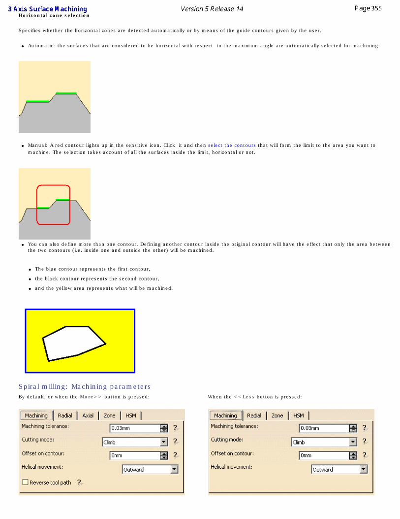
Horizontal zone selection
Specifies whether the horizontal zones are detected automatically or by means of the guide contours given by the user.
● Automatic: the surfaces that are considered to be horizontal with respect to the maximum angle are automatically selected for machining.
● Manual: A red contour lights up in the sensitive icon. Click it and then select the contours that will form the limit to the area you want to machine. The selection takes account of all the surfaces inside the limit, horizontal or not.
● You can also define more than one contour. Defining another contour inside the original contour will have the effect that only the area between the two contours (i.e. inside one and outside the other) will be machined.
● The blue contour represents the first contour,
● the black contour represents the second contour,
● and the yellow area represents what will be machined.
Spiral milling: Machining parameters
By default, or when the More>> button is pressed: When the <<Less button is pressed:
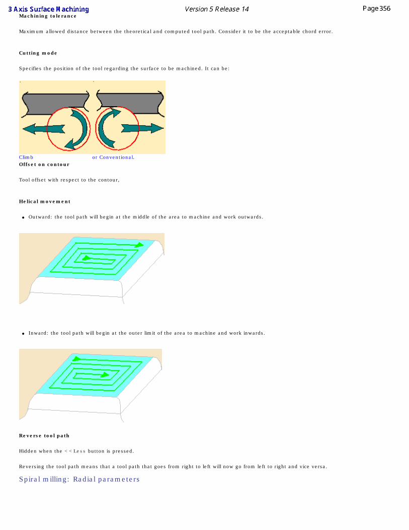
Machining tolerance
Maximum allowed distance between the theoretical and computed tool path. Consider it to be the acceptable chord error.
Cutting mode
Specifies the position of the tool regarding the surface to be machined. It can be:
Climb or Conventional.Offset on contour
Tool offset with respect to the contour,
Helical movement
● Outward: the tool path will begin at the middle of the area to machine and work outwards.
● Inward: the tool path will begin at the outer limit of the area to machine and work inwards.
Reverse tool path
Hidden when the <<Less button is pressed.
Reversing the tool path means that a tool path that goes from right to left will now go from left to right and vice versa.
Spiral milling: Radial parameters
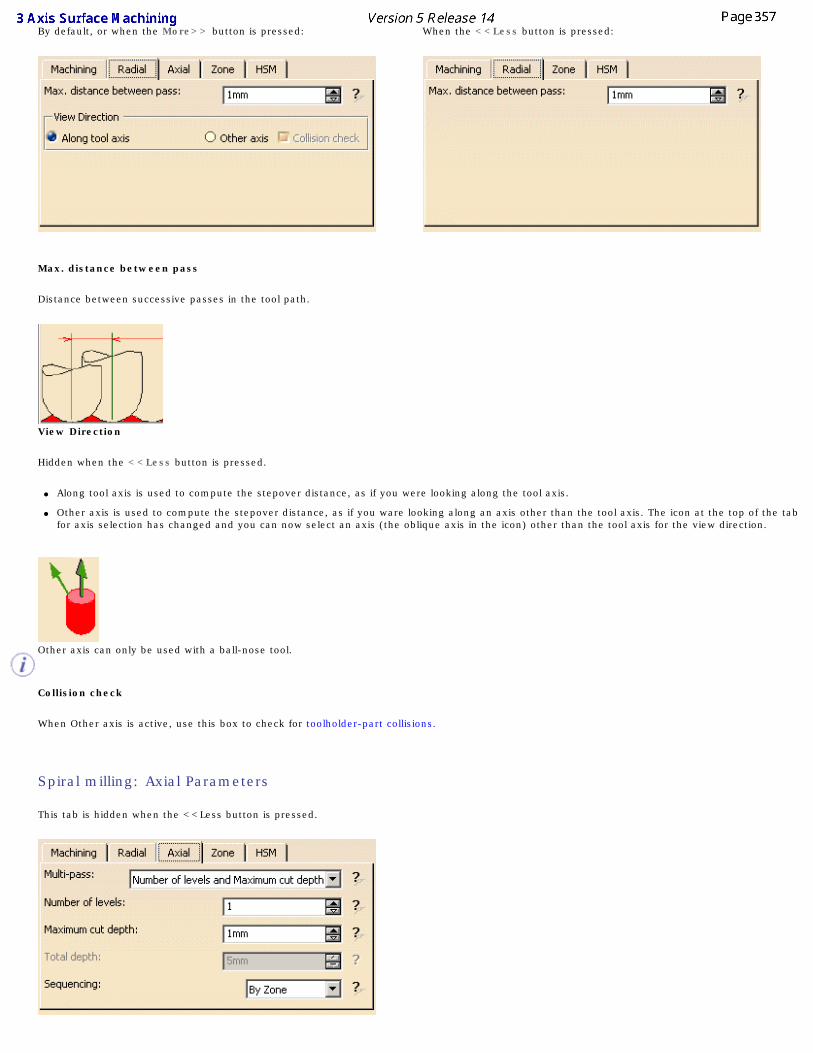
By default, or when the More>> button is pressed:
When the <<Less button is pressed:
Max. distance between pass
Distance between successive passes in the tool path.
View Direction
Hidden when the <<Less button is pressed.
● Along tool axis is used to compute the stepover distance, as if you were looking along the tool axis.
● Other axis is used to compute the stepover distance, as if you ware looking along an axis other than the tool axis. The icon at the top of the tab for axis selection has changed and you can now select an axis (the oblique axis in the icon) other than the tool axis for the view direction.
Other axis can only be used with a ball-nose tool.
Collision check
When Other axis is active, use this box to check for toolholder-part collisions.
Spiral milling: Axial Parameters
This tab is hidden when the <<Less button is pressed.
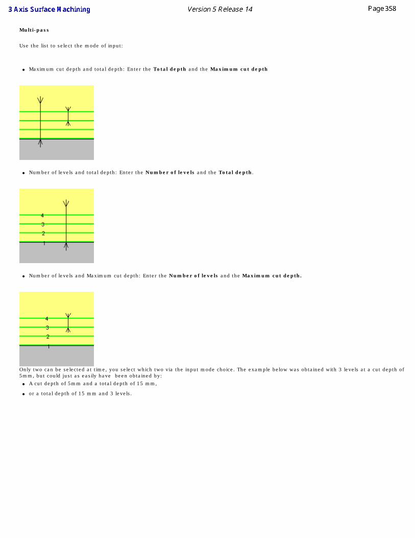
Multi-pass
Use the list to select the mode of input:
● Maximum cut depth and total depth: Enter the Total depth and the Maximum cut depth
● Number of levels and total depth: Enter the Number of levels and the Total depth.
● Number of levels and Maximum cut depth: Enter the Number of levels and the Maximum cut depth.
Only two can be selected at time, you select which two via the input mode choice. The example below was obtained with 3 levels at a cut depth of 5mm, but could just as easily have been obtained by:
● A cut depth of 5mm and a total depth of 15 mm,
● or a total depth of 15 mm and 3 levels.
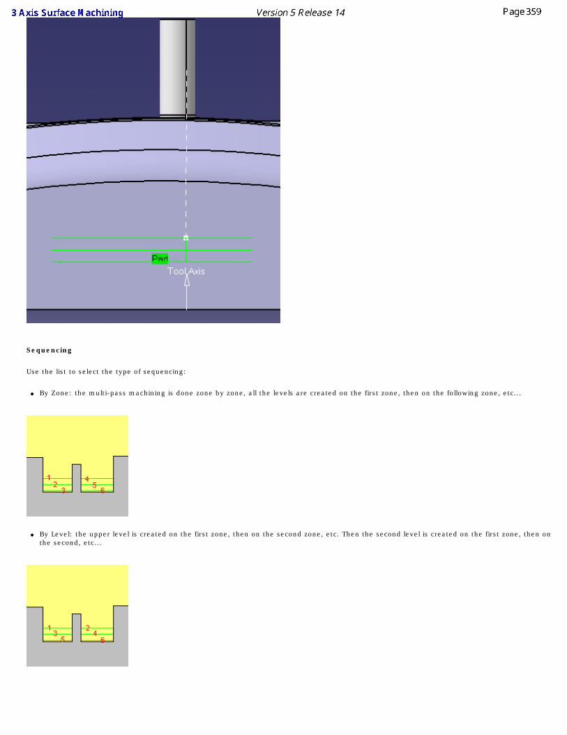
Sequencing
Use the list to select the type of sequencing:
● By Zone: the multi-pass machining is done zone by zone, all the levels are created on the first zone, then on the following zone, etc...
● By Level: the upper level is created on the first zone, then on the second zone, etc. Then the second level is created on the first zone, then on
the second, etc...
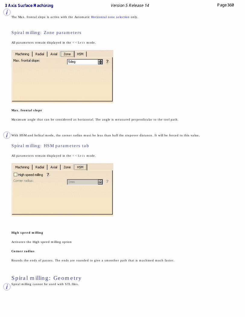
The Max. frontal slope is active with the Automatic Horizontal zone selection only.
Spiral milling: Zone parameters
All parameters remain displayed in the <<Less mode.
Max. frontal slope
Maximum angle that can be considered as horizontal. The angle is measured perpendicular to the tool path.
With HSM and helical mode, the corner radius must be less than half the stepover distance. It will be forced to this value.
Spiral milling: HSM parameters tab
All parameters remain displayed in the <<Less mode.
High speed milling
Activates the High speed milling option
Corner radius
Rounds the ends of passes. The ends are rounded to give a smoother path that is machined much faster.
Spiral milling: Geometry Spiral milling cannot be used with STL files.
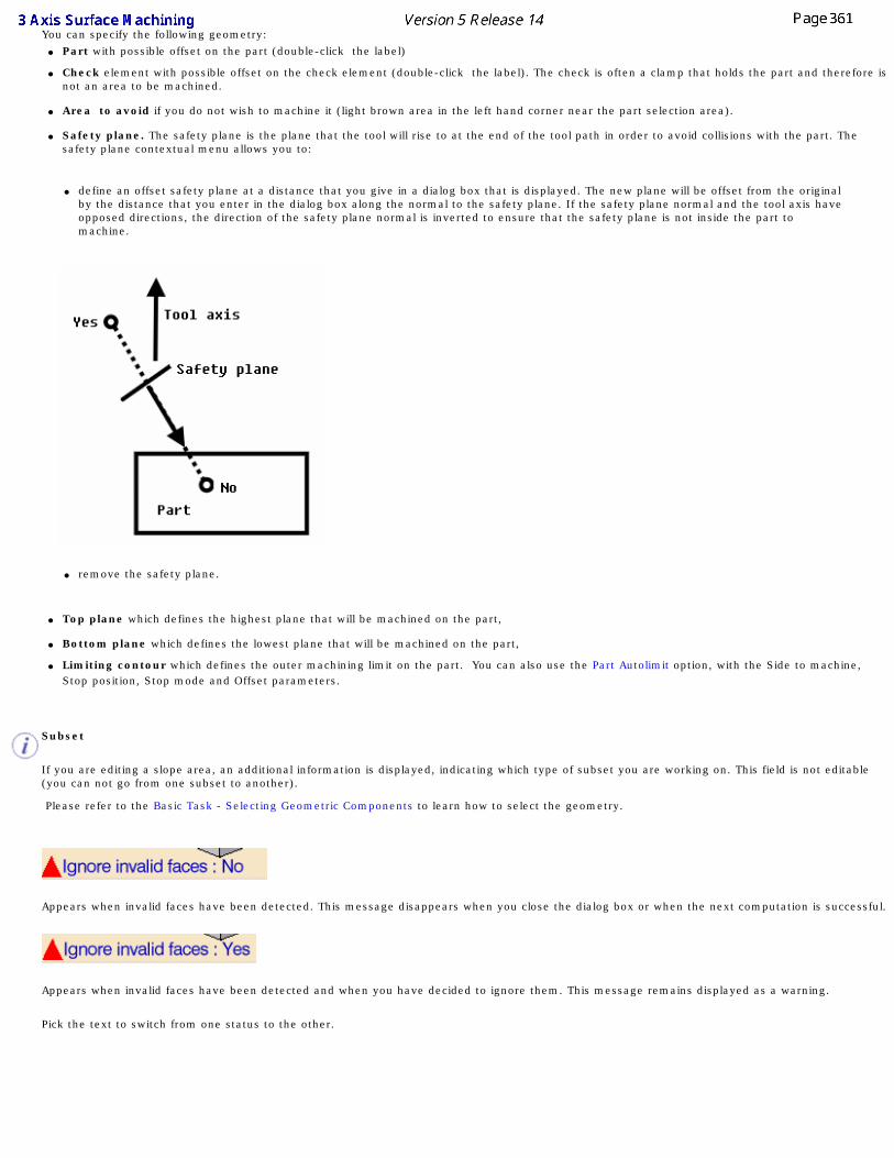
You can specify the following geometry: ● Part with possible offset on the part (double-click the label)
● Check element with possible offset on the check element (double-click the label). The check is often a clamp that holds the part and therefore is not an area to be machined.
● Area to avoid if you do not wish to machine it (light brown area in the left hand corner near the part selection area).
● Safety plane. The safety plane is the plane that the tool will rise to at the end of the tool path in order to avoid collisions with the part. The
safety plane contextual menu allows you to:
● define an offset safety plane at a distance that you give in a dialog box that is displayed. The new plane will be offset from the original by the distance that you enter in the dialog box along the normal to the safety plane. If the safety plane normal and the tool axis have opposed directions, the direction of the safety plane normal is inverted to ensure that the safety plane is not inside the part to machine.
● remove the safety plane.
● Top plane which defines the highest plane that will be machined on the part,
● Bottom plane which defines the lowest plane that will be machined on the part,
● Limiting contour which defines the outer machining limit on the part. You can also use the Part Autolimit option, with the Side to machine, Stop position, Stop mode and Offset parameters.
Subset
If you are editing a slope area, an additional information is displayed, indicating which type of subset you are working on. This field is not editable (you can not go from one subset to another).
Please refer to the Basic Task - Selecting Geometric Components to learn how to select the geometry.
Appears when invalid faces have been detected. This message disappears when you close the dialog box or when the next computation is successful.
Appears when invalid faces have been detected and when you have decided to ignore them. This message remains displayed as a warning.
Pick the text to switch from one status to the other.
Contour-driven ParametersThe information in this section will help you create and edit Contour-driven operations in your Manufacturing Program.
Select the Contour-driven icon then the geometry of the part to machine .
A number of strategy parameters are available. You should choose the cycle type (between contours, parallel contours or spine contour) before setting any of the other parameters. The parameters that you can use depend on the cycle type you choose:
Between Contours:
In the machining strategy tab, use
● the sensitive icon:
● to define the tool axis,
● to visualize the tool path style that you chose.
Parallel contour:
In the machining strategy tab, use
● the sensitive icon:
● to define the tool axis,
● to visualize the tool path style that you chose.
Spine contour:
In the machining strategy tab, use
● the sensitive icon:
● to define the tool axis,
● to visualize the tool path style that you chose.
● the Machining tab to define:
● the Tool path style,
● the Machining tolerance,
● activate the Reverse tool path and Max Discretization (with its Step and Distribution mode) options.
● the Machining tab to define:
● the Tool path style,
● the Machining tolerance,
● activate the Reverse tool path and Max Discretization with its Step and Distribution mode) options.
● the Machining tab to define:
● the Tool path style,
● the Machining tolerance,
● activate the Reverse tool path and Max Discretization (with its Step and Distribution mode) options.
● the Radial tab to define the stepover type:
● Constant (though Max. distance between pass, Scallop height)
● Constant on part or Maximum on part (through Distance, Sweeping strategy, Reference, Position, Offset)
● Via scallop height (Max. distance between pass, Min. distance between pass, Scallop height)
● the Position on guide
● the Offset on guide
● or activate the Along tool axis or Other axis options.
● the Radial tab to define:
● Constant (though Max. distance between pass, Scallop height),
● Constant on part (through Distance, Sweeping strategy, Reference, Position, Offset)
● Via scallop height (through Maximum and Minimum distances, Scallop height)
or activate the Along tool axis or Other axis options.
● the Radial tab to define:
● Constant (though Max. distance between pass, Scallop height),
● Via scallop height (through Maximum and Minimum distances, Scallop height)
or activate the Along tool axis or Other axis options.
● the Axial tab to define:
● the Multi-pass,
● the Number of levels,
● the Maximum cut depth,
● the Total depth.
● the Axial tab to define:
● the Multi-pass,
● the Number of levels,
● the Maximum cut depth,
● the Total depth.
● the Axial tab to define:
● the Multi-pass,
● the Number of levels,
● the Maximum cut depth,
● the Total depth.
● the Strategy tab to activate:
● the Pencil rework option,
● the Strategy tab:
● to activate the Pencil rework option,
● to define the Offset on contour,
● the Maximum width to machine,
● the Stepover side,
● the Direction,
● the Initial tool position.
● the Strategy tab is not available.
● the Island tab:
● to activate the Island skip or the Direct option,
● to define the Feedrate length.
● the Island tab:
● to activate the Island skip or the Direct option,
● to define the Feedrate length.
● the Island tab:
● to activate the Island skip or the Direct option,
● to define the Feedrate length.
Specify the tool to use (you have the choice of end mill or conical tools for this operation) and the feedrates and spindle speeds .
You can also define transition paths in your machining operations by means of NC macros as needed.
The Machined Zone tab has been removed from the machining strategy. However, if you are working on a process created in a R8 release, with values other than the default values, the Machined Zone tab is displayed with the maximum slope that can be considered to be horizontal (any area that is considered to be horizontal will not be machined),
If you are working on a process created in a R9 release or higher, the slope parameters are managed by the slope area.
Contour-Driven: Strategy parameters
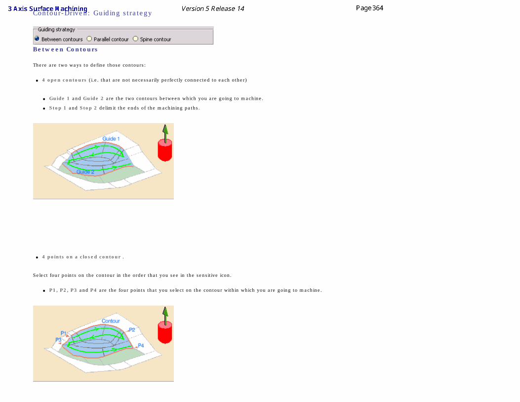
Contour-Driven: Guiding strategy
Between Contours
There are two ways to define those contours:
● 4 open contours (i.e. that are not necessarily perfectly connected to each other)
● Guide 1 and Guide 2 are the two contours between which you are going to machine.
● Stop 1 and Stop 2 delimit the ends of the machining paths.
● 4 points on a closed contour .
Select four points on the contour in the order that you see in the sensitive icon.
● P1, P2, P3 and P4 are the four points that you select on the contour within which you are going to machine.
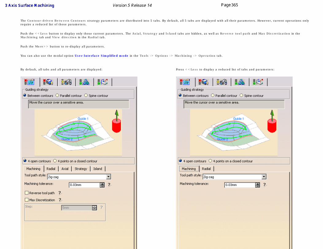
The Contour-driven Between Contours strategy parameters are distributed into 5 tabs. By default, all 5 tabs are displayed with all their parameters. However, current operations only require a reduced list of those parameters.
Push the <<Less button to display only those current parameters. The Axial, Strategy and Island tabs are hidden, as well as Reverse tool path and Max Discretization in the Machining tab and View direction in the Radial tab.
Push the More>> button to re-display all parameters.
You can also use the modal option User Interface Simplified mode in the Tools -> Options -> Machining -> Operation tab.
By default, all tabs and all parameters are displayed: Press <<Less to display a reduced list of tabs and parameters:
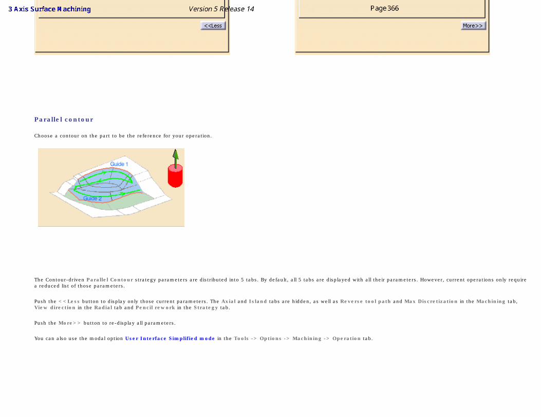
Parallel contour
Choose a contour on the part to be the reference for your operation.
The Contour-driven Parallel Contour strategy parameters are distributed into 5 tabs. By default, all 5 tabs are displayed with all their parameters. However, current operations only require a reduced list of those parameters.
Push the <<Less button to display only those current parameters. The Axial and Island tabs are hidden, as well as Reverse tool path and Max Discretization in the Machining tab, View direction in the Radial tab and Pencil rework in the Strategy tab.
Push the More>> button to re-display all parameters.
You can also use the modal option User Interface Simplified mode in the Tools -> Options -> Machining -> Operation tab.
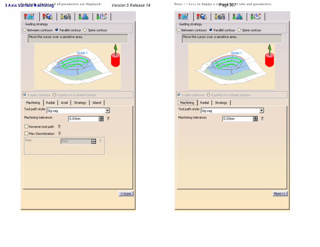
By default, all tabs and all parameters are displayed: Press <<Less to display a reduced list of tabs and parameters:
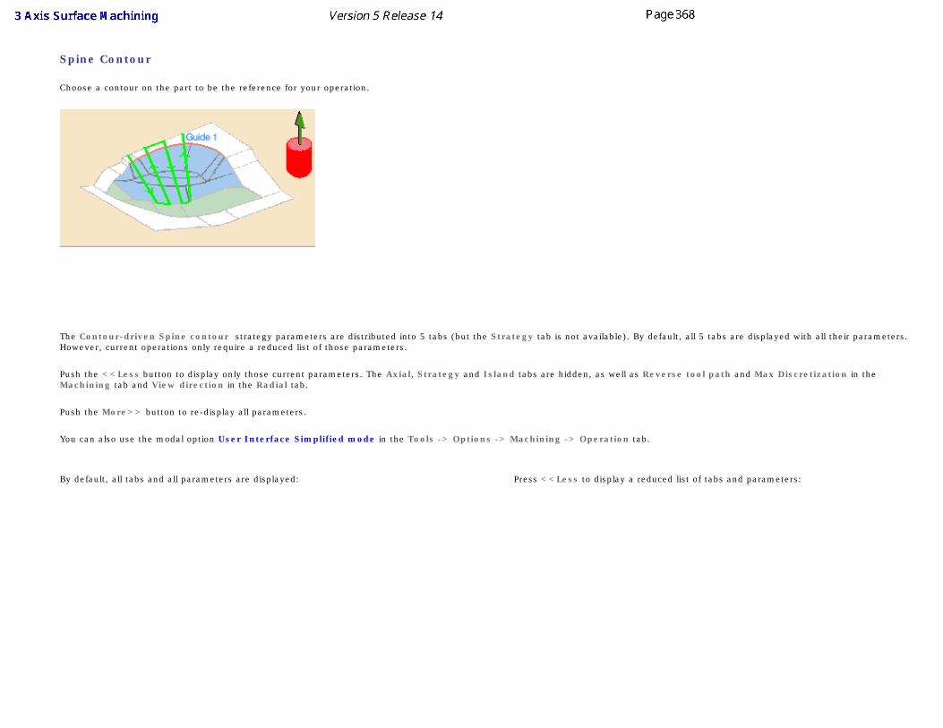
Spine Contour
Choose a contour on the part to be the reference for your operation.
The Contour-driven Spine contour strategy parameters are distributed into 5 tabs (but the Strategy tab is not available). By default, all 5 tabs are displayed with all their parameters. However, current operations only require a reduced list of those parameters.
Push the <<Less button to display only those current parameters. The Axial, Strategy and Island tabs are hidden, as well as Reverse tool path and Max Discretization in the Machining tab and View direction in the Radial tab.
Push the More>> button to re-display all parameters.
You can also use the modal option User Interface Simplified mode in the Tools -> Options -> Machining -> Operation tab.
By default, all tabs and all parameters are displayed: Press <<Less to display a reduced list of tabs and parameters:
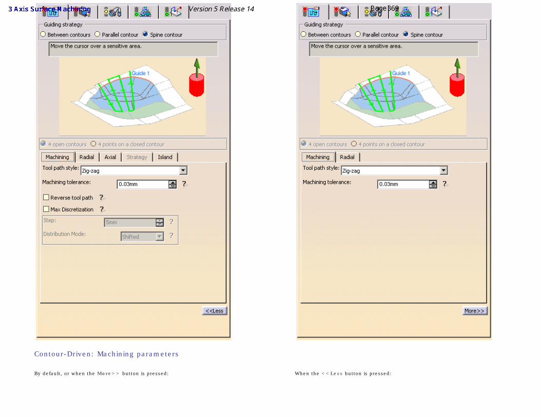
Contour-Driven: Machining parameters
By default, or when the More>> button is pressed: When the <<Less button is pressed:
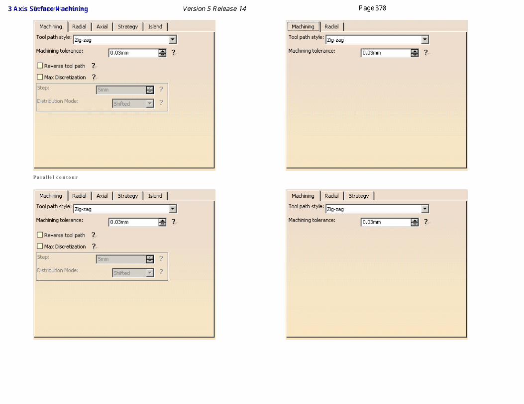
Between contours
Parallel contour
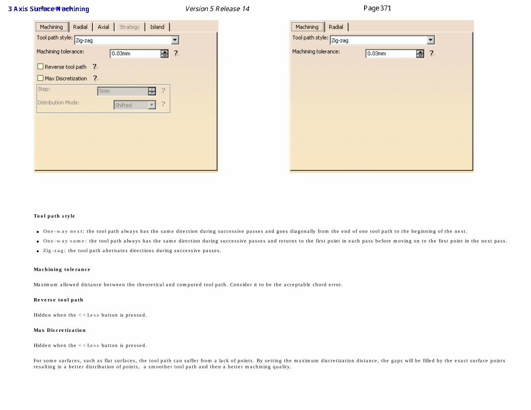
Spine contour
Tool path style
● One-way next: the tool path always has the same direction during successive passes and goes diagonally from the end of one tool path to the beginning of the next.
● One-way same: the tool path always has the same direction during successive passes and returns to the first point in each pass before moving on to the first point in the next pass.
● Zig-zag: the tool path alternates directions during successive passes.
Machining tolerance
Maximum allowed distance between the theoretical and computed tool path. Consider it to be the acceptable chord error.
Reverse tool path
Hidden when the <<Less button is pressed.
Max Discretization
Hidden when the <<Less button is pressed.
For some surfaces, such as flat surfaces, the tool path can suffer from a lack of points. By setting the maximum discretization distance, the gaps will be filled by the exact surface points resulting in a better distribution of points, a smoother tool path and then a better machining quality.
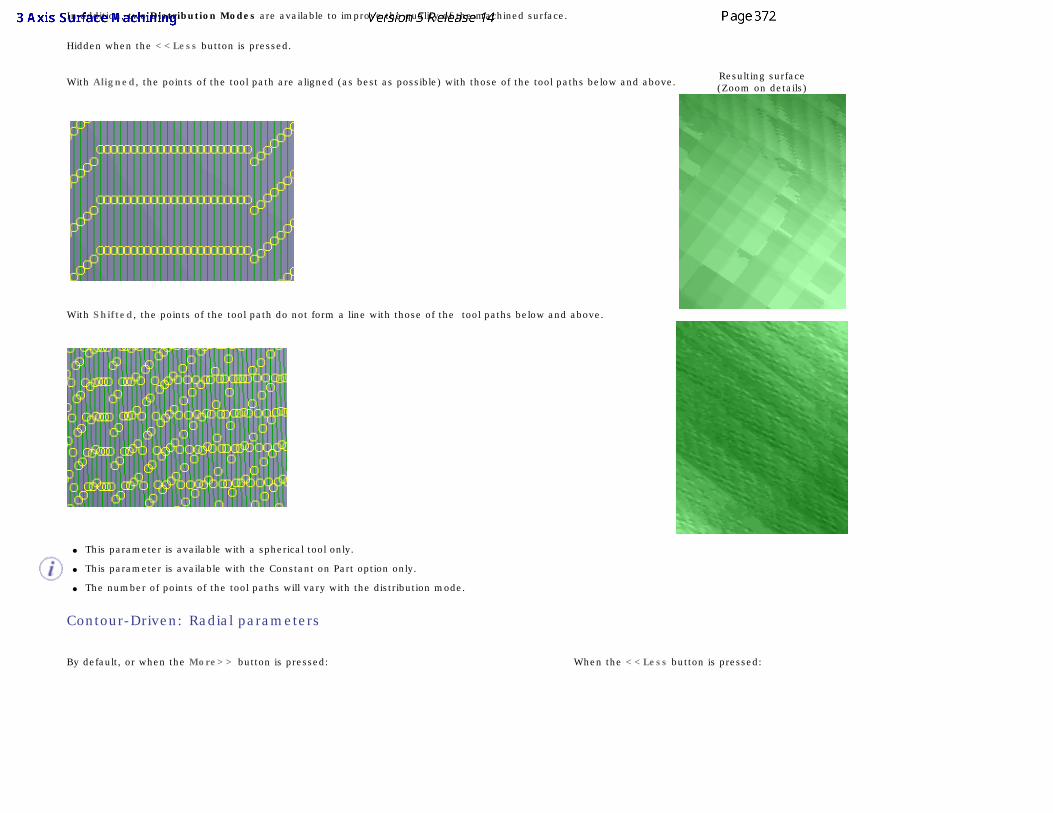
In addition, two Distribution Modes are available to improve the quality of the machined surface.
Hidden when the <<Less button is pressed.
With Aligned, the points of the tool path are aligned (as best as possible) with those of the tool paths below and above. Resulting surface(Zoom on details)
With Shifted, the points of the tool path do not form a line with those of the tool paths below and above.
● This parameter is available with a spherical tool only.
● This parameter is available with the Constant on Part option only.
● The number of points of the tool paths will vary with the distribution mode.
Contour-Driven: Radial parameters
By default, or when the More>> button is pressed: When the <<Less button is pressed:
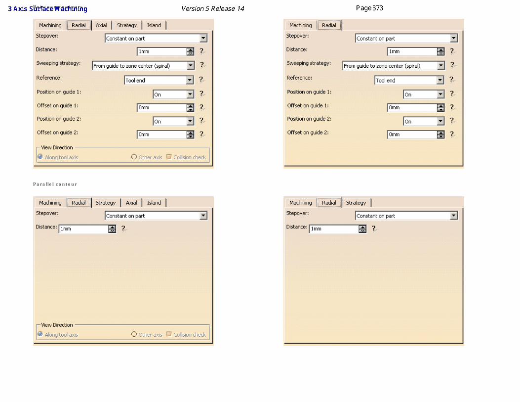
Between contours
Parallel contour
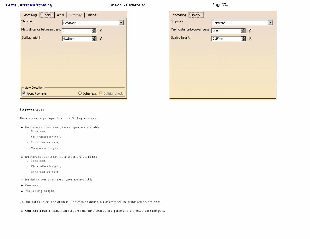
Spine contour
Stepover type:
The stepover type depends on the Guiding strategy:
● for Between contours, those types are available:❍ Constant,
❍ Via scallop height,
❍ Constant on part,
❍ Maximum on part.
● for Parallel contour, those types are available:❍ Constant,
❍ Via scallop height,
❍ Constant on part.
● for Spine contour, those types are available:
● Constant,
● Via scallop height.
Use the list to select one of them. The corresponding parameters will be displayed accordingly.
● Constant: Has a maximum stepover distance defined in a plane and projected onto the part.
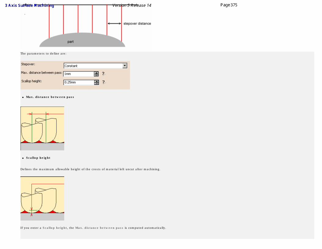
The parameters to define are:
● Max. distance between pass
● Scallop height
Defines the maximum allowable height of the crests of material left uncut after machining.
If you enter a Scallop height, the Max. distance between pass is computed automatically.
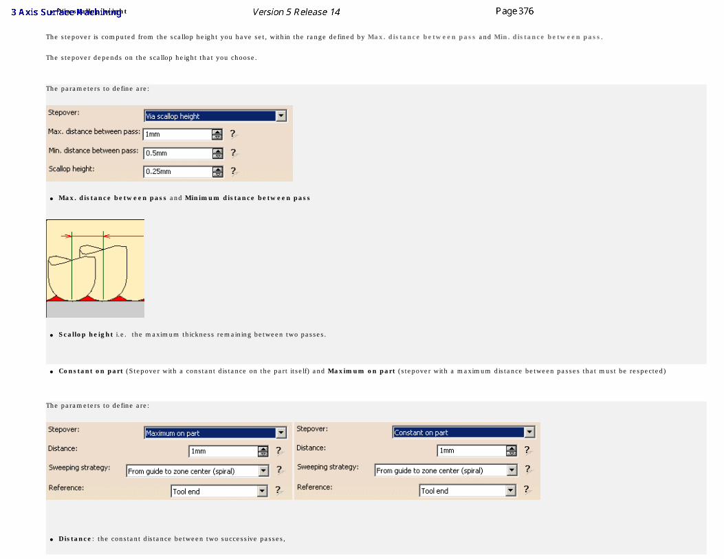
● Via scallop height
The stepover is computed from the scallop height you have set, within the range defined by Max. distance between pass and Min. distance between pass.
The stepover depends on the scallop height that you choose.
The parameters to define are:
● Max. distance between pass and Minimum distance between pass
● Scallop height i.e. the maximum thickness remaining between two passes.
● Constant on part (Stepover with a constant distance on the part itself) and Maximum on part (stepover with a maximum distance between passes that must be respected)
The parameters to define are:
● Distance: the constant distance between two successive passes,
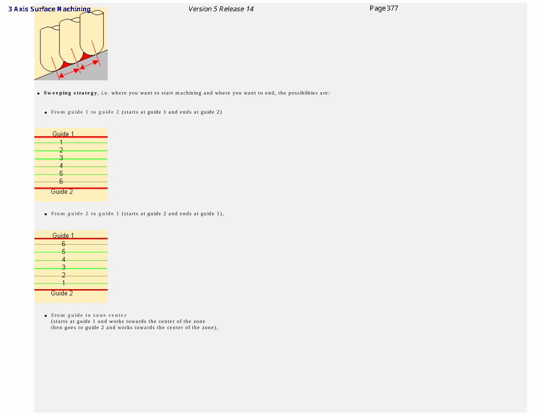
● Sweeping strategy, i.e. where you want to start machining and where you want to end, the possibilities are:
● From guide 1 to guide 2 (starts at guide 1 and ends at guide 2)
● From guide 2 to guide 1 (starts at guide 2 and ends at guide 1),
● From guide to zone center (starts at guide 1 and works towards the center of the zone then goes to guide 2 and works towards the center of the zone),
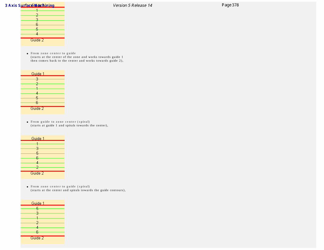
● From zone center to guide (starts at the center of the zone and works towards guide 1 then comes back to the center and works towards guide 2),
● From guide to zone center (spiral) (starts at guide 1 and spirals towards the center),
● From zone center to guide (spiral) (starts at the center and spirals towards the guide contours),
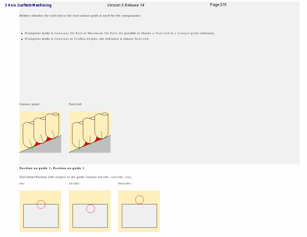
● Reference
Defines whether the tool end or the tool contact point is used for the computation:
● If stepover mode is Constant On Part or Maximum On Part, it's possible to choose a Tool end or a Contact point reference.
● If stepover mode is Constant or Scallop height, the reference is always Tool end.
Contact point: Tool end:
Position on guide 1, Position on guide 2
Tool initial Position with respect to the guide contour (inside, outside, on),
On: Inside: Outside:
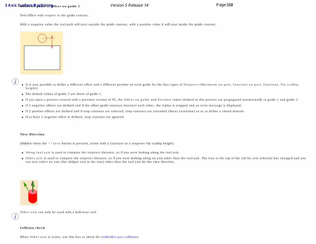
Offset on guide 1, Offset on guide 2
Tool Offset with respect to the guide contour.
With a negative value the tool path will start outside the guide contour, with a positive value it will start inside the guide contour.
● It is now possible to define a different offset and a different position on each guide for the four types of Stepover (Maximum on part, Constant on part, Constant, Via scallop height).
● The default values of guide 2 are those of guide 1.
● If you open a process created with a previous version of V5, the Offset on guide and Position values defined in this process are propagated automatically to guide 1 and guide 2.
● If 2 negative offsets are defined and if the offset guide contours intersect each other, the replay is stopped and an error message is displayed.
● If 2 positive offsets are defined and if stop contours are selected, stop contours are extended (linear extension) so as to define a closed domain.
● If at least 1 negative offset is defined, stop contours are ignored.
View Direction
(Hidden when the <<Less button is pressed, active with a Constant or a stepover Via scallop height)
● Along tool axis is used to compute the stepover distance, as if you were looking along the tool axis.
● Other axis is used to compute the stepover distance, as if you ware looking along an axis other than the tool axis. The icon at the top of the tab for axis selection has changed and you can now select an axis (the oblique axis in the icon) other than the tool axis for the view direction.
Other axis can only be used with a ball-nose tool.
Collision check
When Other axis is active, use this box to check for toolholder-part collisions.
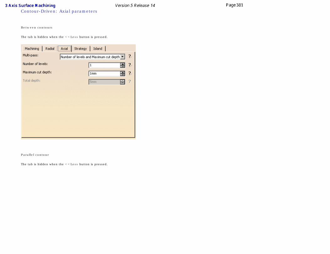
Contour-Driven: Axial parameters
Between contours
The tab is hidden when the <<Less button is pressed.
Parallel contour
The tab is hidden when the <<Less button is pressed.
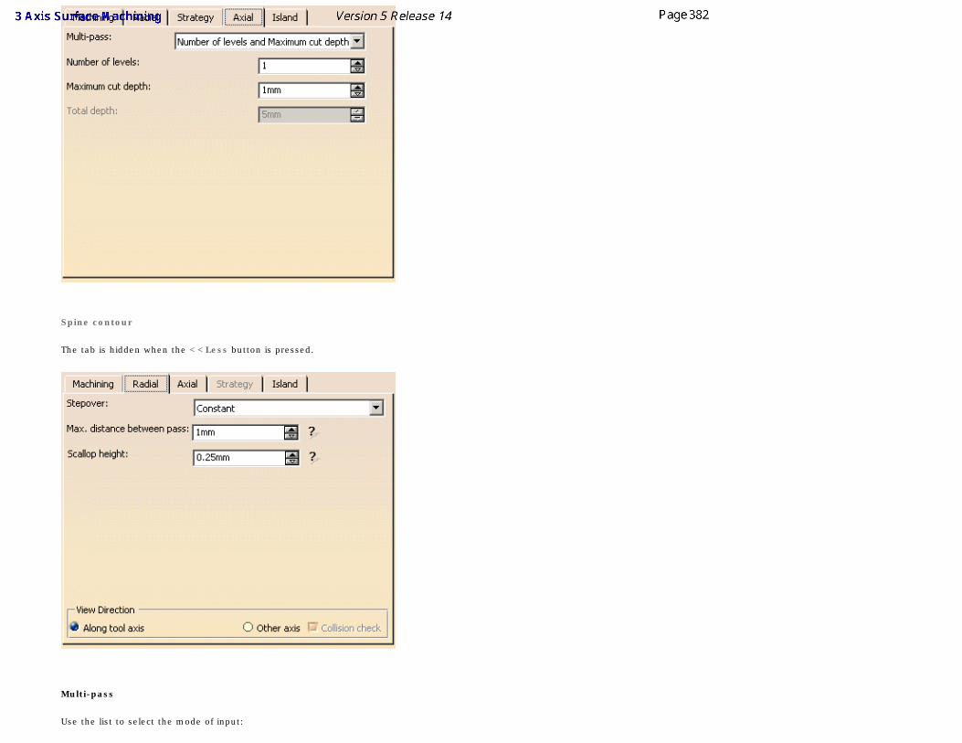
Spine contour
The tab is hidden when the <<Less button is pressed.
Multi-pass
Use the list to select the mode of input:
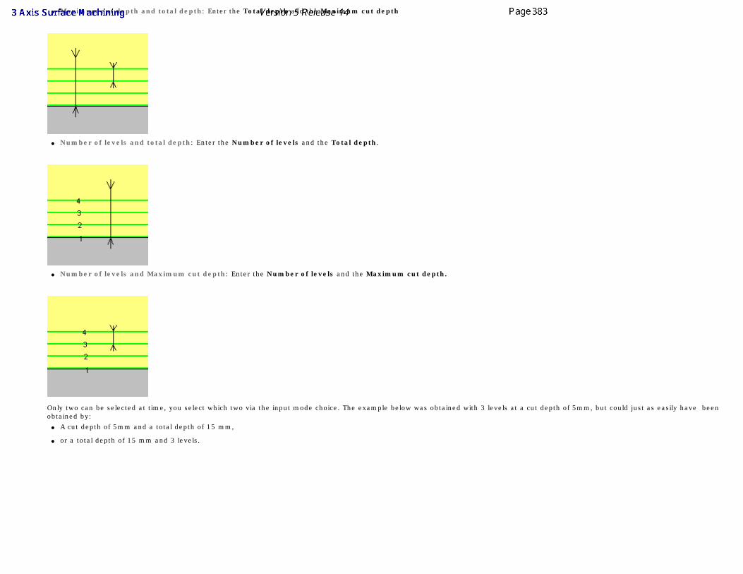
● Maximum cut depth and total depth: Enter the Total depth and the Maximum cut depth
● Number of levels and total depth: Enter the Number of levels and the Total depth.
● Number of levels and Maximum cut depth: Enter the Number of levels and the Maximum cut depth.
Only two can be selected at time, you select which two via the input mode choice. The example below was obtained with 3 levels at a cut depth of 5mm, but could just as easily have been obtained by:
● A cut depth of 5mm and a total depth of 15 mm,
● or a total depth of 15 mm and 3 levels.
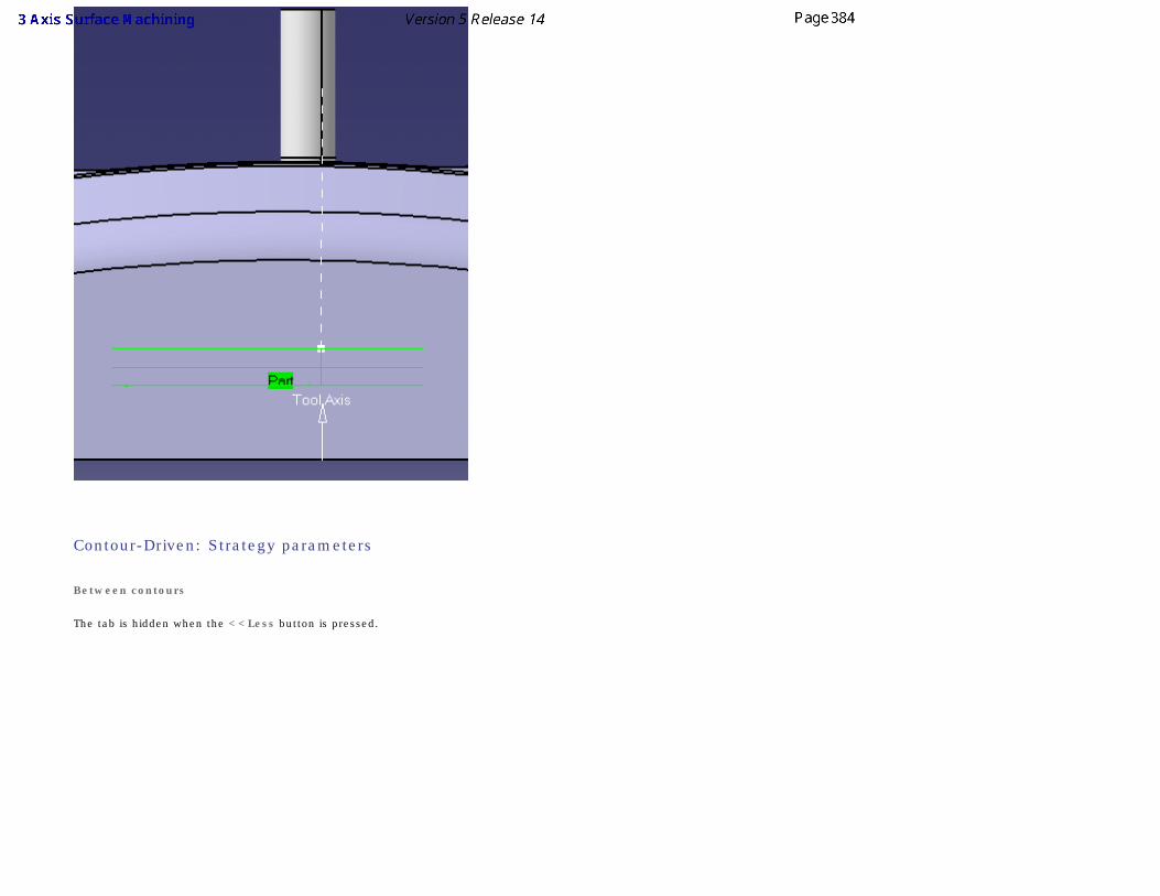
Contour-Driven: Strategy parameters
Between contours
The tab is hidden when the <<Less button is pressed.
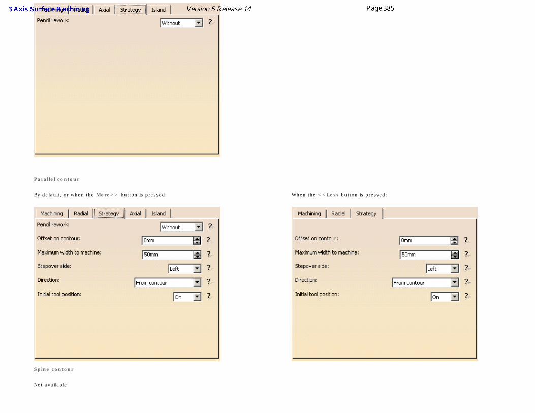
Parallel contour
By default, or when the More>> button is pressed:
When the <<Less button is pressed:
Spine contour
Not available
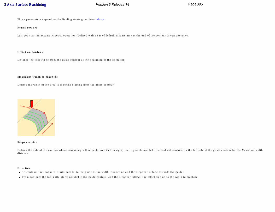
Those parameters depend on the Guiding strategy as listed above.
Pencil rework
Lets you start an automatic pencil operation (defined with a set of default parameters) at the end of the contour driven operation.
Offset on contour
Distance the tool will be from the guide contour at the beginning of the operation
Maximum width to machine
Defines the width of the area to machine starting from the guide contour,
Stepover side
Defines the side of the contour where machining will be performed (left or right), i.e. if you choose Left, the tool will machine on the left side of the guide contour for the Maximum width distance,
Direction ● To contour: the tool path starts parallel to the guide at the width to machine and the stepover is done towards the guide
● From contour: the tool path starts parallel to the guide contour and the stepover follows the offset side up to the width to machine
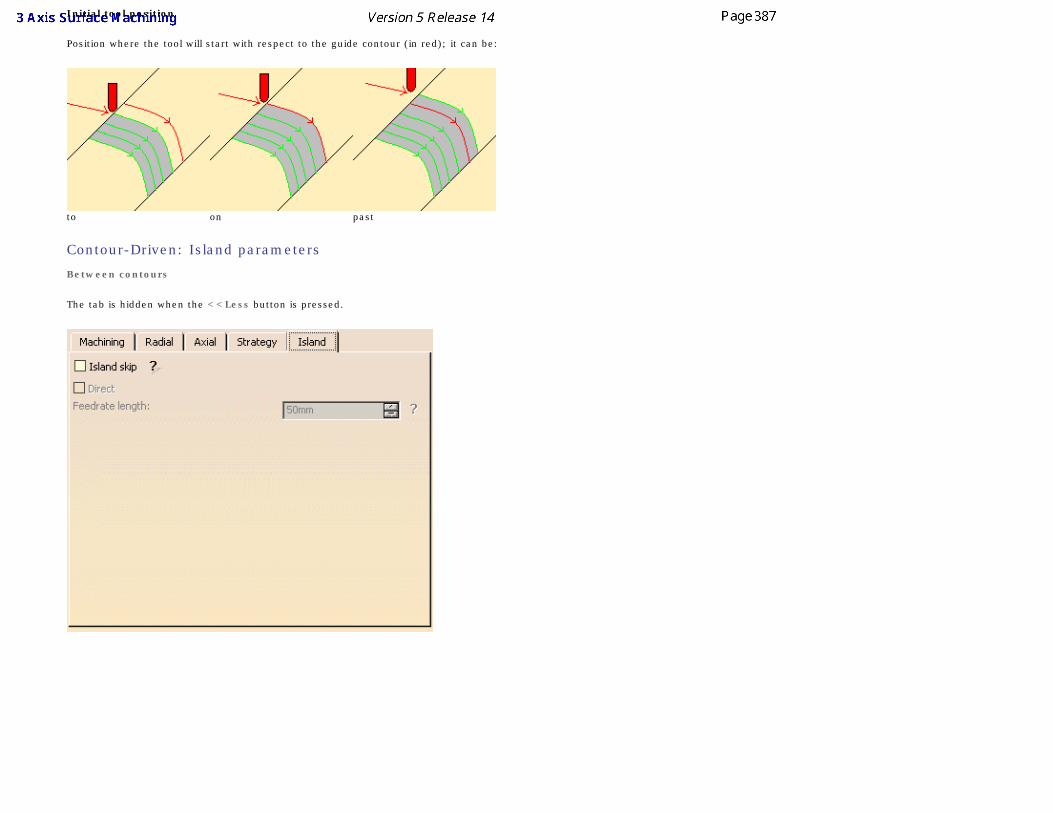
Initial tool position
Position where the tool will start with respect to the guide contour (in red); it can be:
to on past
Contour-Driven: Island parameters
Between contours
The tab is hidden when the <<Less button is pressed.
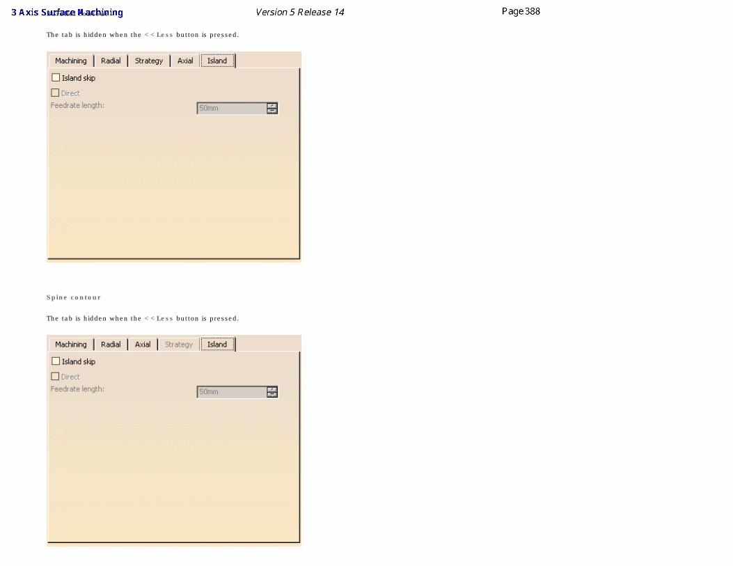
Parallel contour
The tab is hidden when the <<Less button is pressed.
Spine contour
The tab is hidden when the <<Less button is pressed.
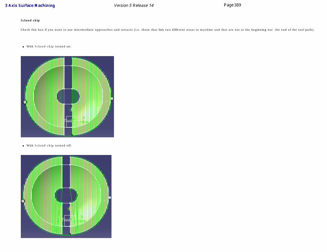
Island skip
Check this box if you want to use intermediate approaches and retracts (i.e. those that link two different areas to machine and that are not at the beginning nor the end of the tool path).
● With Island skip turned on:
● With Island skip turned off:
Direct
When this box is checked, the tool is not allowed to rise on intermediate approaches and retracts. When Direct is not checked, the tool will rise to 10 mm on intermediate approaches and retracts.
Feedrate length
Defines the distance beyond which tool path straight lines will be replaced by intermediate approaches and retracts. In the picture below, the Feedrate length was set to 45 mm. Note that the gaps that were less than 45 mm are crossed by a straight line tool path and those that are greater than 45 mm are crossed with a standard intermediate tool path with an approach and a retract.
Feedrate length is only active if the Direct option is checked.
Contour-Driven: GeometryYou can specify the following geometry:
● Part with possible offset on part (double-click the label).
● Check element with possible offset on check element (double-click the label). The check is often a clamp that holds the part and therefore is not an area to be machined.
The tool path quality is improved along "between paths" if check surfaces are selected.
● Area to avoid if you do not wish to machine it (light brown area in the left hand corner near the part selection area).
● Safety plane. The safety plane is the plane that the tool will rise to at the end of the tool path in order to avoid collisions with the part. The safety plane contextual menu allows you to
define:
● an offset safety plane at a distance that you give in a dialog box that is displayed. The new plane will be offset from the original by the distance that you enter in the dialog box along the normal to the safety plane. If the safety plane normal and the tool axis have opposed directions, the direction of the safety plane normal is inverted to ensure that the safety plane is not inside the part to machine.
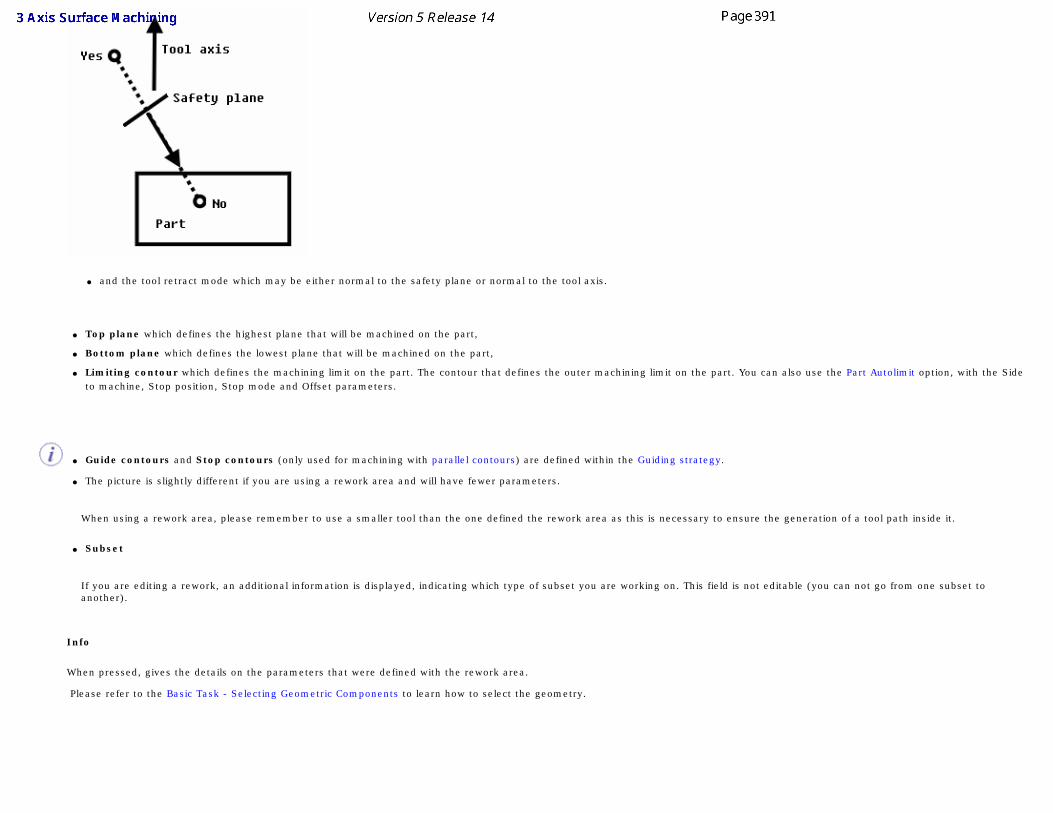
● and the tool retract mode which may be either normal to the safety plane or normal to the tool axis.
● Top plane which defines the highest plane that will be machined on the part,
● Bottom plane which defines the lowest plane that will be machined on the part,
● Limiting contour which defines the machining limit on the part. The contour that defines the outer machining limit on the part. You can also use the Part Autolimit option, with the Side to machine, Stop position, Stop mode and Offset parameters.
● Guide contours and Stop contours (only used for machining with parallel contours) are defined within the Guiding strategy.
● The picture is slightly different if you are using a rework area and will have fewer parameters.
When using a rework area, please remember to use a smaller tool than the one defined the rework area as this is necessary to ensure the generation of a tool path inside it.
● Subset
If you are editing a rework, an additional information is displayed, indicating which type of subset you are working on. This field is not editable (you can not go from one subset to another).
Info
When pressed, gives the details on the parameters that were defined with the rework area.
Please refer to the Basic Task - Selecting Geometric Components to learn how to select the geometry.
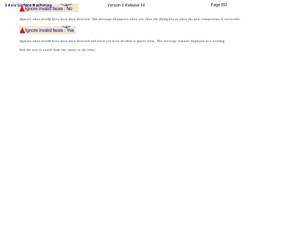
Appears when invalid faces have been detected. This message disappears when you close the dialog box or when the next computation is successful.
Appears when invalid faces have been detected and when you have decided to ignore them. This message remains displayed as a warning.
Pick the text to switch from one status to the other.
Pencil ParametersThe information in this section will help you create and edit pencil operations in your Manufacturing Program.
Select the Pencil icon , then select the geometry to be machined .
A number of strategy parameters are available:
● in the Machining tab to define:
❍ the Machining tolerance,
❍ the Axial direction,
❍ the Minimum change length,
❍ the Cutting mode.
● in the Axial tab to define:
❍ the Multi-pass input parameters,
❍ the Number of levels,
❍ the Maximum cut depth,
❍ the Total depth,
❍ the Sequencing mode.
Specify the tool to use (the tools that can be used with this type of operation are end mill or conical tools), the feedrates and
spindle speeds ,
You can also define transition paths in your machining operations by means of NC macros as needed.
Pencil: Strategy parameters
The Sweeping strategy parameters are distributed into 2 tabs. By default, all 2 tabs are displayed with all their parameters. However, current operations only require a reduced list of those parameters.
Push the <<Less button to display only those current parameters:
● the Axial tab is hidden,
Push the More>> button to re-display all parameters.
You can also use the modal option User Interface Simplified mode in the Tools -> Options -> Machining -> Operation tab.
By default, all tabs and all parameters are displayed: Press <<Less to display a reduced list of tabs and parameters:
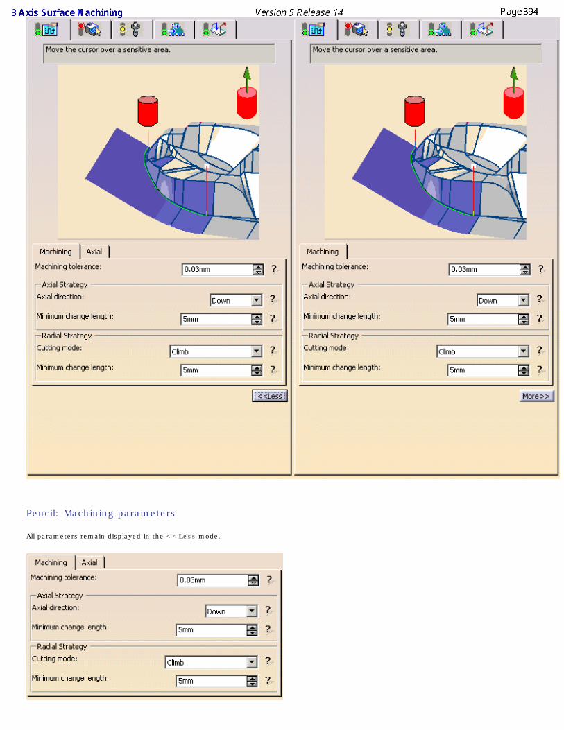
Pencil: Machining parameters
All parameters remain displayed in the <<Less mode.
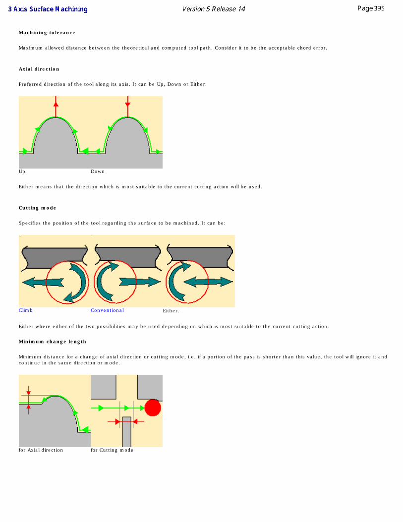
Machining tolerance
Maximum allowed distance between the theoretical and computed tool path. Consider it to be the acceptable chord error.
Axial direction
Preferred direction of the tool along its axis. It can be Up, Down or Either.
Up Down
Either means that the direction which is most suitable to the current cutting action will be used.
Cutting mode
Specifies the position of the tool regarding the surface to be machined. It can be:
Climb Conventional Either.
Either where either of the two possibilities may be used depending on which is most suitable to the current cutting action.
Minimum change length
Minimum distance for a change of axial direction or cutting mode, i.e. if a portion of the pass is shorter than this value, the tool will ignore it and continue in the same direction or mode.
for Axial direction for Cutting mode
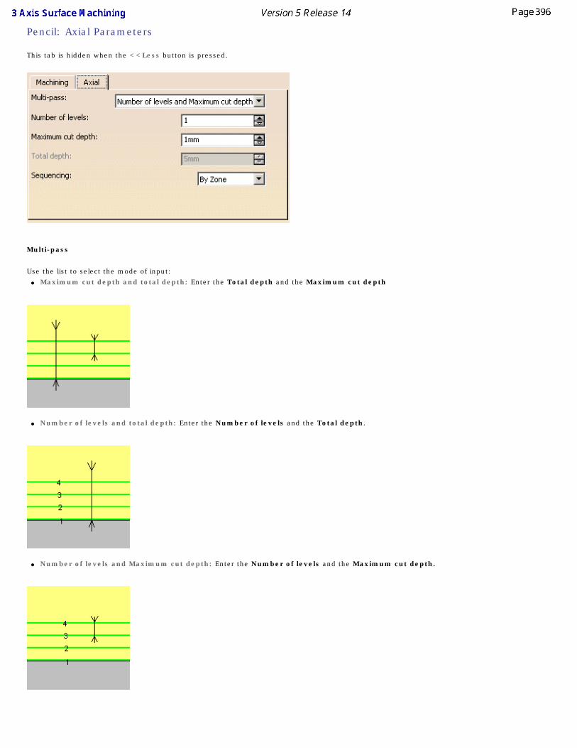
Pencil: Axial Parameters
This tab is hidden when the <<Less button is pressed.
Multi-pass
Use the list to select the mode of input:● Maximum cut depth and total depth: Enter the Total depth and the Maximum cut depth
● Number of levels and total depth: Enter the Number of levels and the Total depth.
● Number of levels and Maximum cut depth: Enter the Number of levels and the Maximum cut depth.
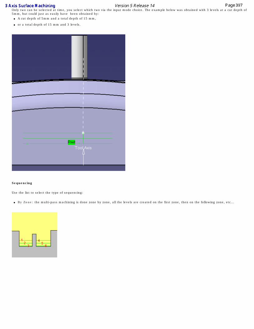
Only two can be selected at time, you select which two via the input mode choice. The example below was obtained with 3 levels at a cut depth of 5mm, but could just as easily have been obtained by:
● A cut depth of 5mm and a total depth of 15 mm,
● or a total depth of 15 mm and 3 levels.
Sequencing
Use the list to select the type of sequencing:
● By Zone: the multi-pass machining is done zone by zone, all the levels are created on the first zone, then on the following zone, etc...
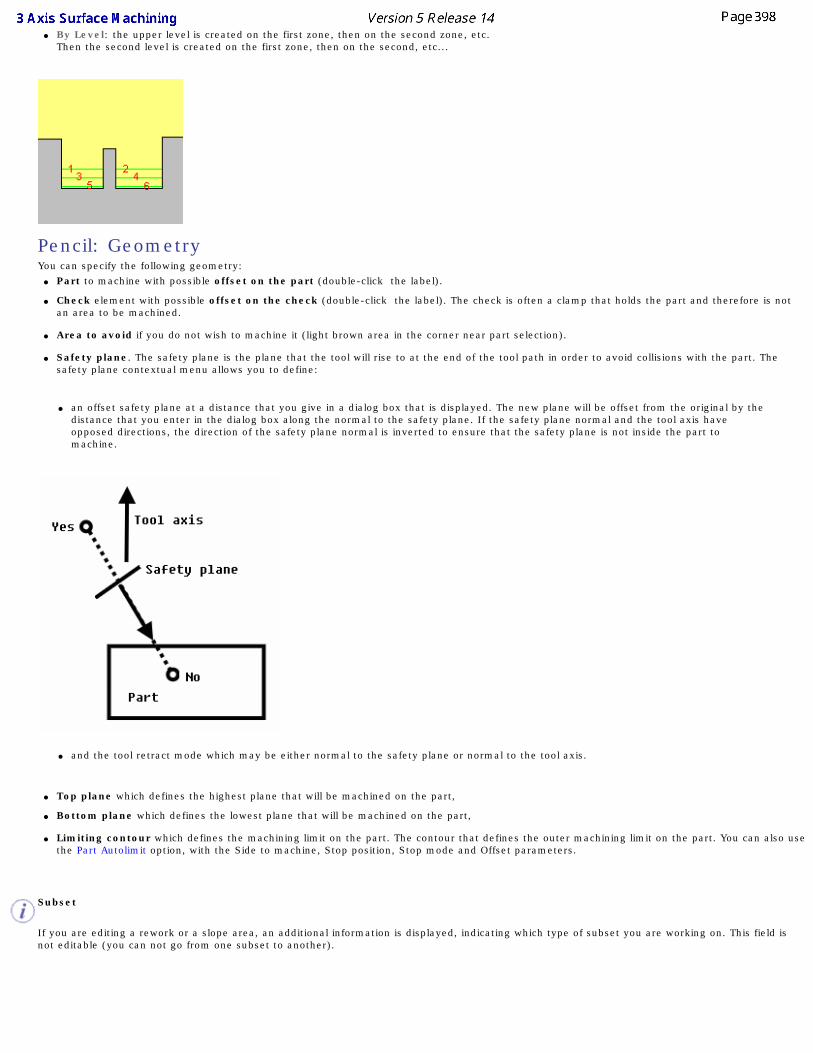
● By Level: the upper level is created on the first zone, then on the second zone, etc.
Then the second level is created on the first zone, then on the second, etc...
Pencil: GeometryYou can specify the following geometry:
● Part to machine with possible offset on the part (double-click the label).
● Check element with possible offset on the check (double-click the label). The check is often a clamp that holds the part and therefore is not an area to be machined.
● Area to avoid if you do not wish to machine it (light brown area in the corner near part selection).
● Safety plane. The safety plane is the plane that the tool will rise to at the end of the tool path in order to avoid collisions with the part. The
safety plane contextual menu allows you to define:
● an offset safety plane at a distance that you give in a dialog box that is displayed. The new plane will be offset from the original by the distance that you enter in the dialog box along the normal to the safety plane. If the safety plane normal and the tool axis have opposed directions, the direction of the safety plane normal is inverted to ensure that the safety plane is not inside the part to machine.
● and the tool retract mode which may be either normal to the safety plane or normal to the tool axis.
● Top plane which defines the highest plane that will be machined on the part,
● Bottom plane which defines the lowest plane that will be machined on the part,
● Limiting contour which defines the machining limit on the part. The contour that defines the outer machining limit on the part. You can also use the Part Autolimit option, with the Side to machine, Stop position, Stop mode and Offset parameters.
Subset
If you are editing a rework or a slope area, an additional information is displayed, indicating which type of subset you are working on. This field is not editable (you can not go from one subset to another).

Info
When pressed, gives the details on the parameters that were defined with the rework area. Please refer to the Basic Task - Selecting Geometric Components to learn how to select the geometry.
Appears when invalid faces have been detected. This message disappears when you close the dialog box or when the next computation is successful.
Appears when invalid faces have been detected and when you have decided to ignore them. This message remains displayed as a warning.
Pick the text to switch from one status to the other.
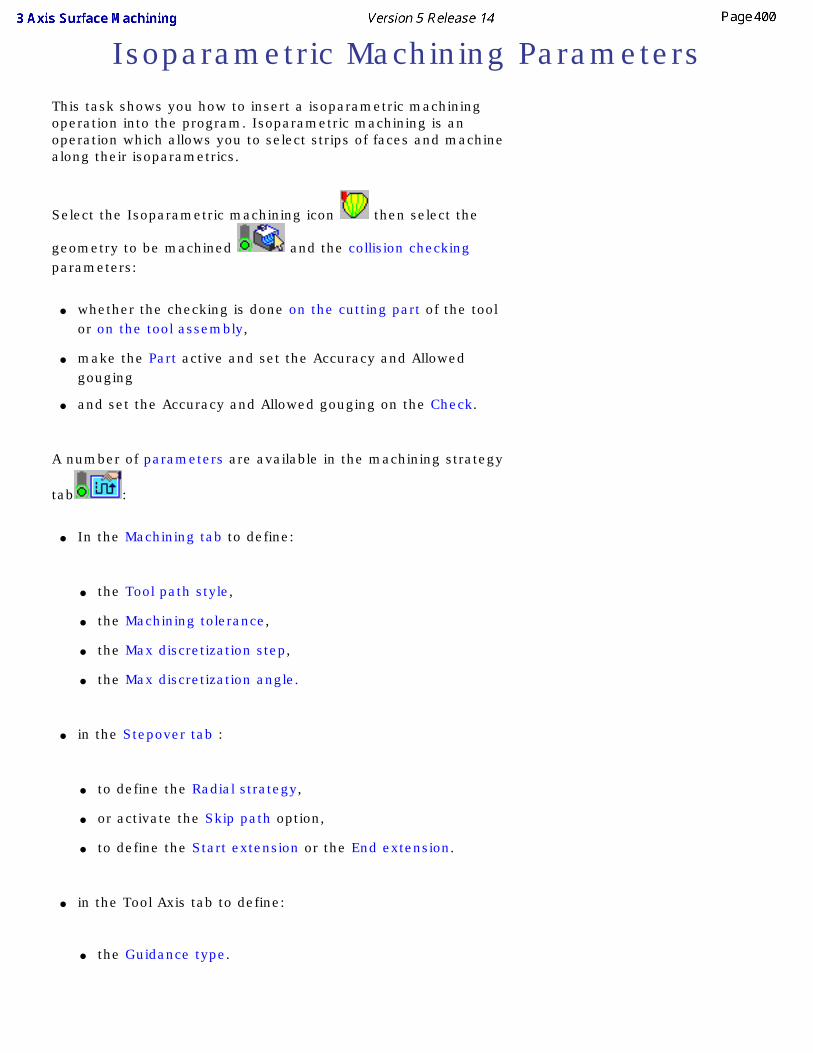
Isoparametric Machining ParametersThis task shows you how to insert a isoparametric machining operation into the program. Isoparametric machining is an operation which allows you to select strips of faces and machine along their isoparametrics.
Select the Isoparametric machining icon then select the
geometry to be machined and the collision checking parameters:
● whether the checking is done on the cutting part of the tool or on the tool assembly,
● make the Part active and set the Accuracy and Allowed gouging
● and set the Accuracy and Allowed gouging on the Check.
A number of parameters are available in the machining strategy
tab :
● In the Machining tab to define:
● the Tool path style,
● the Machining tolerance,
● the Max discretization step,
● the Max discretization angle.
● in the Stepover tab :
● to define the Radial strategy,
● or activate the Skip path option,
● to define the Start extension or the End extension.
● in the Tool Axis tab to define:
● the Guidance type.
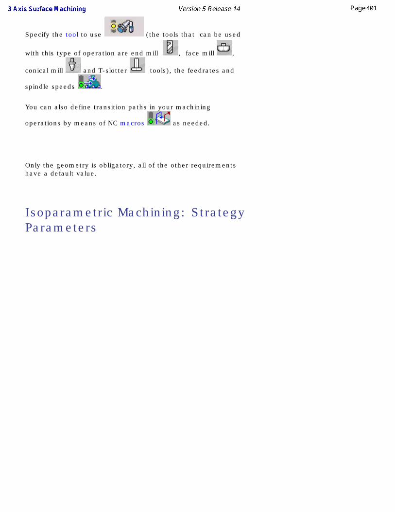
Specify the tool to use (the tools that can be used
with this type of operation are end mill , face mill ,
conical mill and T-slotter tools), the feedrates and
spindle speeds .
You can also define transition paths in your machining
operations by means of NC macros as needed.
Only the geometry is obligatory, all of the other requirements have a default value.
Isoparametric Machining: Strategy Parameters
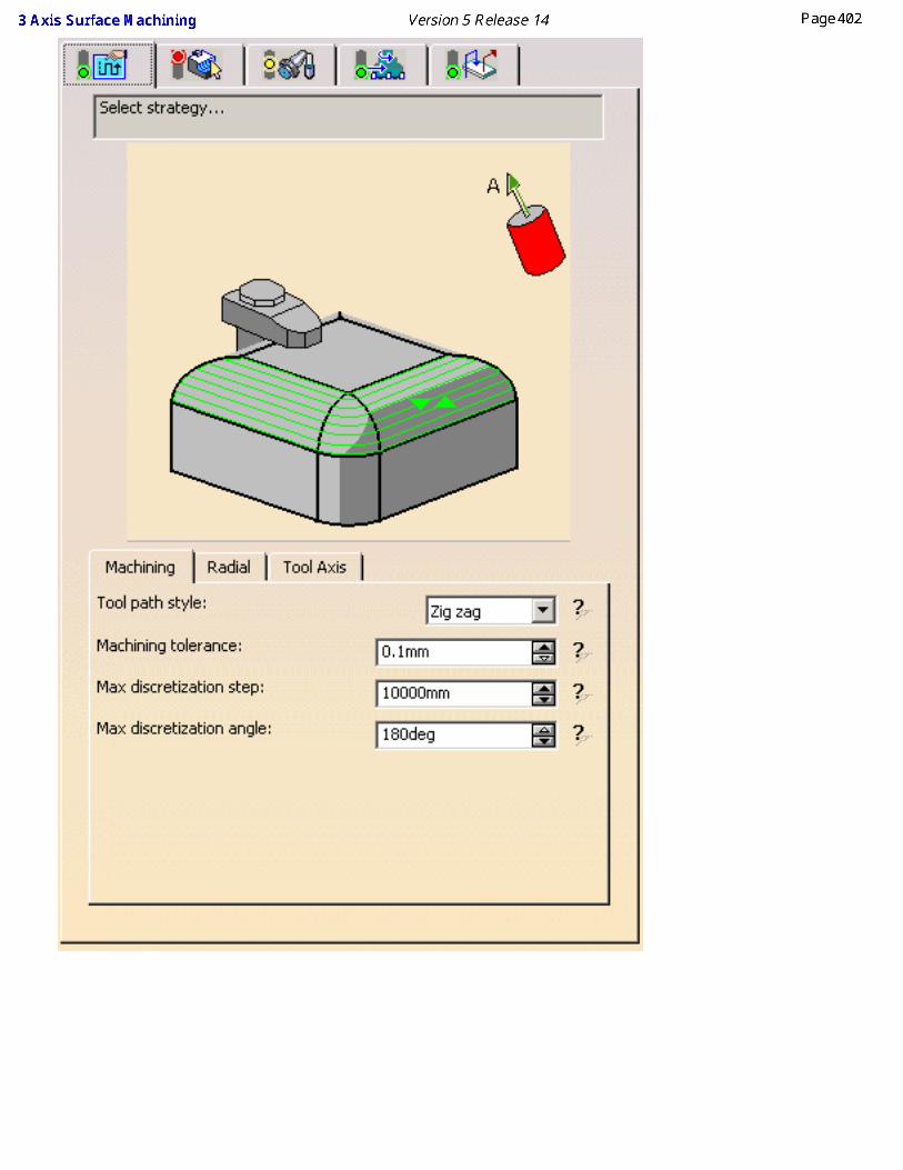
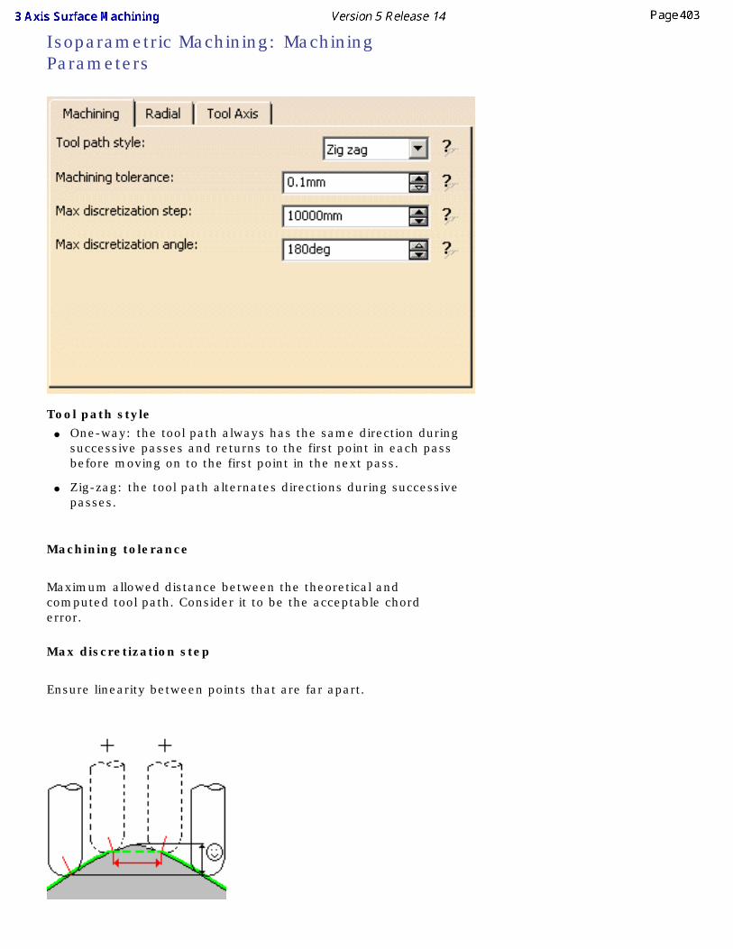
Isoparametric Machining: Machining Parameters
Tool path style ● One-way: the tool path always has the same direction during
successive passes and returns to the first point in each pass before moving on to the first point in the next pass.
● Zig-zag: the tool path alternates directions during successive passes.
Machining tolerance
Maximum allowed distance between the theoretical and computed tool path. Consider it to be the acceptable chord error.
Max discretization step
Ensure linearity between points that are far apart.
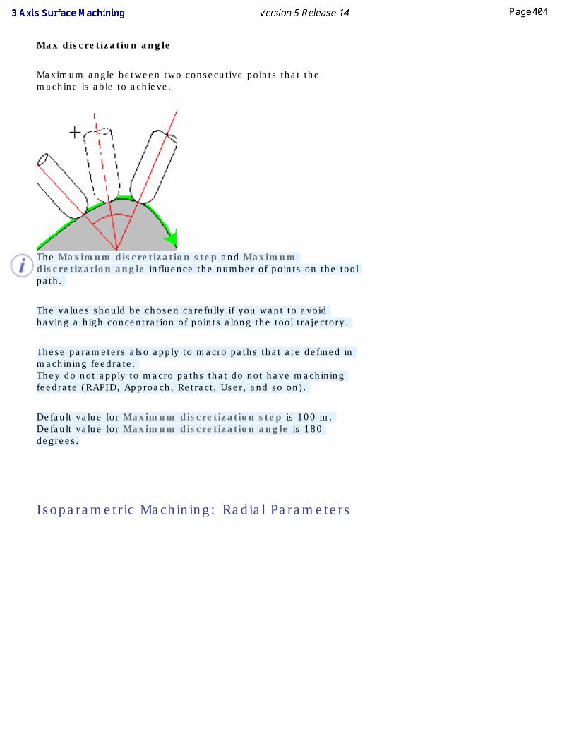
Max discretization angle
Maximum angle between two consecutive points that the machine is able to achieve.
The Maximum discretization step and Maximum discretization angle influence the number of points on the tool path.
The values should be chosen carefully if you want to avoid having a high concentration of points along the tool trajectory.
These parameters also apply to macro paths that are defined in machining feedrate. They do not apply to macro paths that do not have machining feedrate (RAPID, Approach, Retract, User, and so on).
Default value for Maximum discretization step is 100 m. Default value for Maximum discretization angle is 180 degrees.
Isoparametric Machining: Radial Parameters
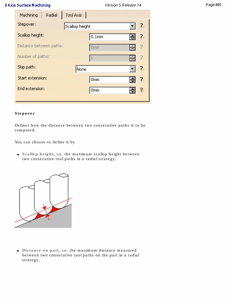
Stepover
Defines how the distance between two consecutive paths is to be computed.
You can choose to define it by
● Scallop height, i.e. the maximum scallop height between two consecutive tool paths in a radial strategy.
● Distance on part, i.e. the maximum distance measured between two consecutive tool paths on the part in a radial strategy.
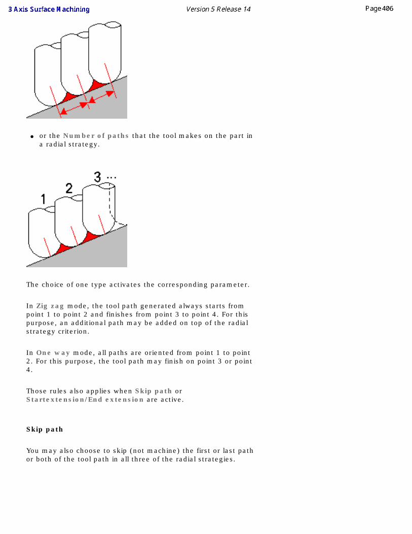
● or the Number of paths that the tool makes on the part in a radial strategy.
The choice of one type activates the corresponding parameter.
In Zig zag mode, the tool path generated always starts from point 1 to point 2 and finishes from point 3 to point 4. For this purpose, an additional path may be added on top of the radial strategy criterion.
In One way mode, all paths are oriented from point 1 to point 2. For this purpose, the tool path may finish on point 3 or point 4.
Those rules also applies when Skip path or Startextension/End extension are active.
Skip path
You may also choose to skip (not machine) the first or last path or both of the tool path in all three of the radial strategies.
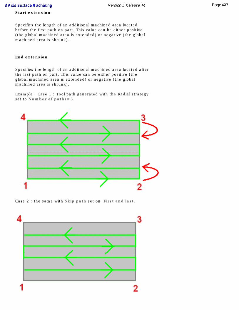
Start extension
Specifies the length of an additional machined area located before the first path on part. This value can be either positive (the global machined area is extended) or negative (the global machined area is shrunk).
End extension
Specifies the length of an additional machined area located after the last path on part. This value can be either positive (the global machined area is extended) or negative (the global machined area is shrunk).
Example : Case 1 : Tool path generated with the Radial strategy
set to Number of paths=5.
Case 2 : the same with Skip path set on First and last.
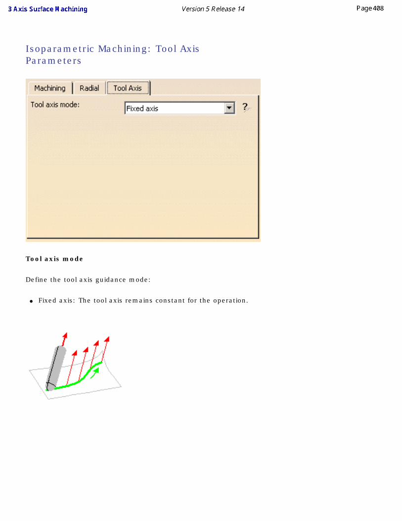
Isoparametric Machining: Tool Axis Parameters
Tool axis mode
Define the tool axis guidance mode:
● Fixed axis: The tool axis remains constant for the operation.
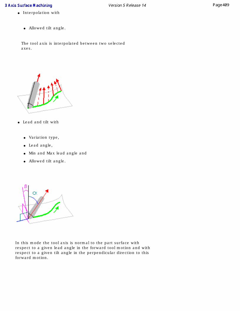
● Interpolation with
● Allowed tilt angle.
The tool axis is interpolated between two selected axes.
● Lead and tilt with
● Variation type,
● Lead angle,
● Min and Max lead angle and
● Allowed tilt angle.
In this mode the tool axis is normal to the part surface with respect to a given lead angle in the forward tool motion and with respect to a given tilt angle in the perpendicular direction to this forward motion.
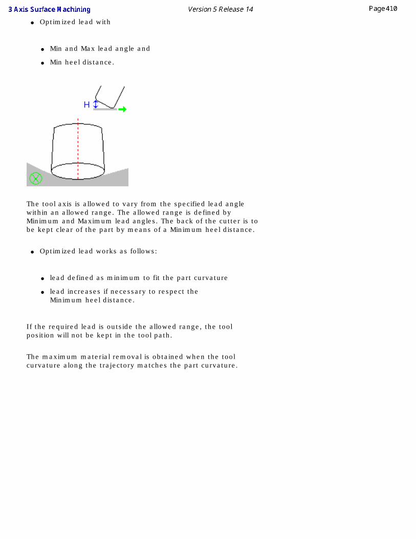
● Optimized lead with
● Min and Max lead angle and
● Min heel distance.
The tool axis is allowed to vary from the specified lead angle within an allowed range. The allowed range is defined by Minimum and Maximum lead angles. The back of the cutter is to be kept clear of the part by means of a Minimum heel distance.
● Optimized lead works as follows:
● lead defined as minimum to fit the part curvature
● lead increases if necessary to respect the Minimum heel distance.
If the required lead is outside the allowed range, the tool position will not be kept in the tool path.
The maximum material removal is obtained when the tool curvature along the trajectory matches the part curvature.
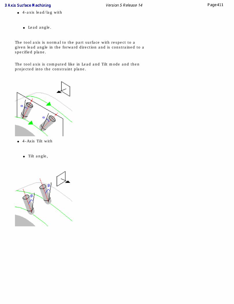
● 4-axis lead/lag with
● Lead angle.
The tool axis is normal to the part surface with respect to a given lead angle in the forward direction and is constrained to a specified plane.
The tool axis is computed like in Lead and Tilt mode and then projected into the constraint plane.
● 4-Axis Tilt with
● Tilt angle,
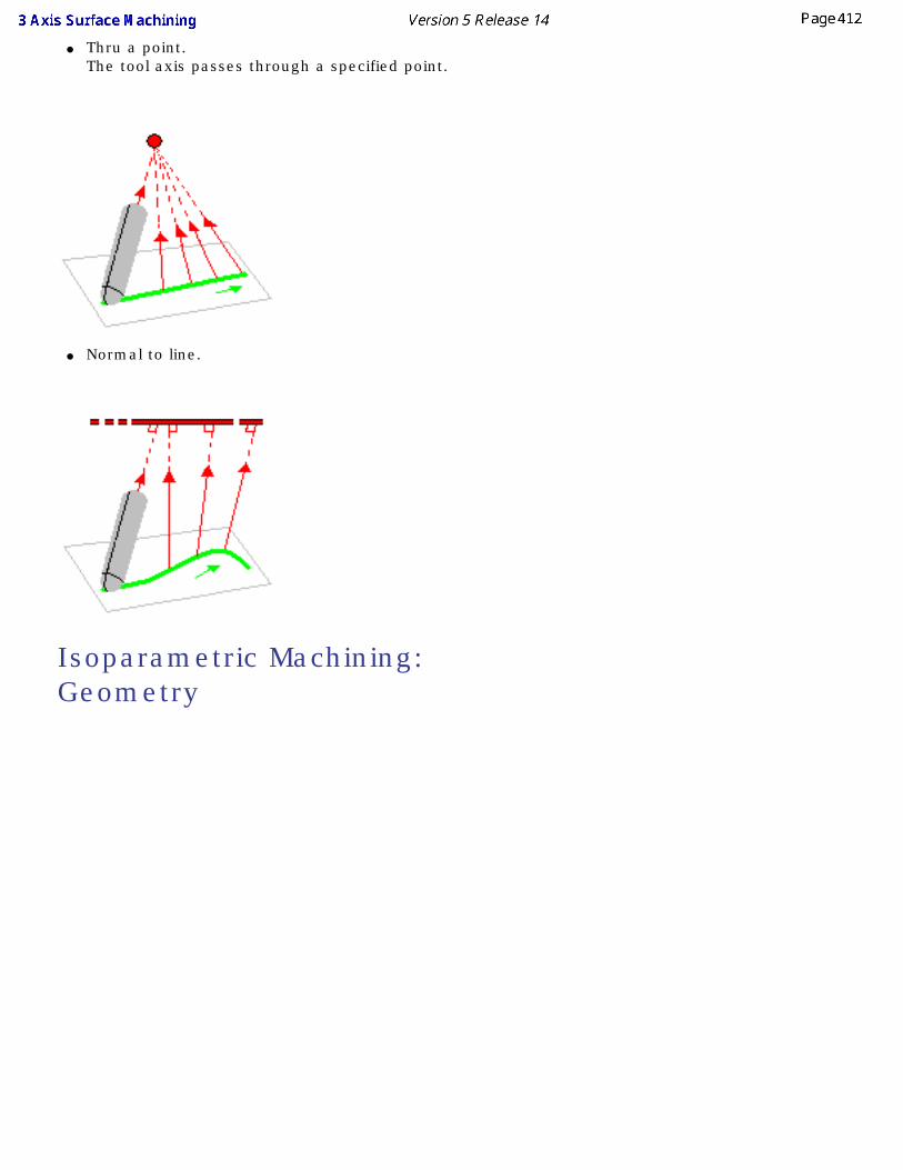
● Thru a point. The tool axis passes through a specified point.
● Normal to line.
Isoparametric Machining: Geometry
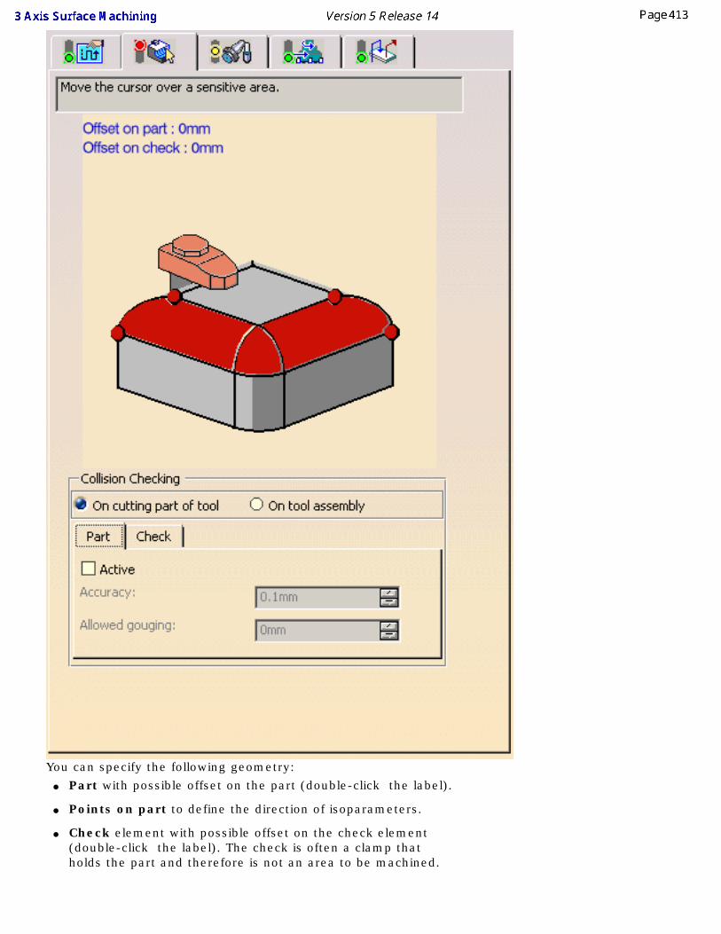
You can specify the following geometry: ● Part with possible offset on the part (double-click the label).
● Points on part to define the direction of isoparameters.
● Check element with possible offset on the check element (double-click the label). The check is often a clamp that holds the part and therefore is not an area to be machined.
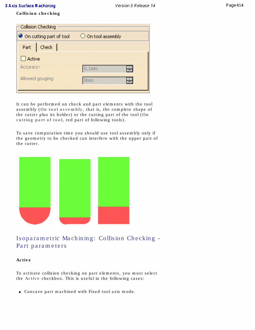
Collision checking
It can be performed on check and part elements with the tool assembly (On tool assembly, that is, the complete shape of the cutter plus its holder) or the cutting part of the tool (On cutting part of tool, red part of following tools).
To save computation time you should use tool assembly only if the geometry to be checked can interfere with the upper part of the cutter.
Isoparametric Machining: Collision Checking - Part parameters
Active
To activate collision checking on part elements, you must select the Active checkbox. This is useful in the following cases:
● Concave part machined with Fixed tool axis mode.
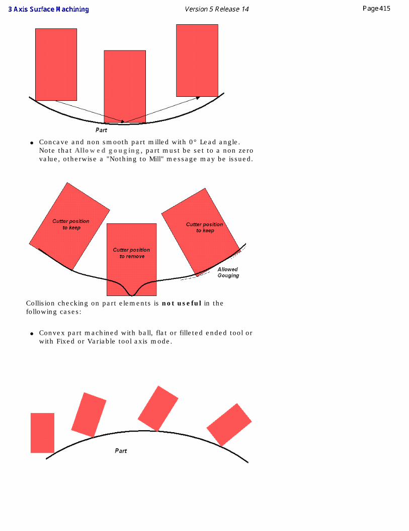
● Concave and non smooth part milled with 0° Lead angle. Note that Allowed gouging, part must be set to a non zero value, otherwise a "Nothing to Mill" message may be issued.
Collision checking on part elements is not useful in the following cases:
● Convex part machined with ball, flat or filleted ended tool or with Fixed or Variable tool axis mode.
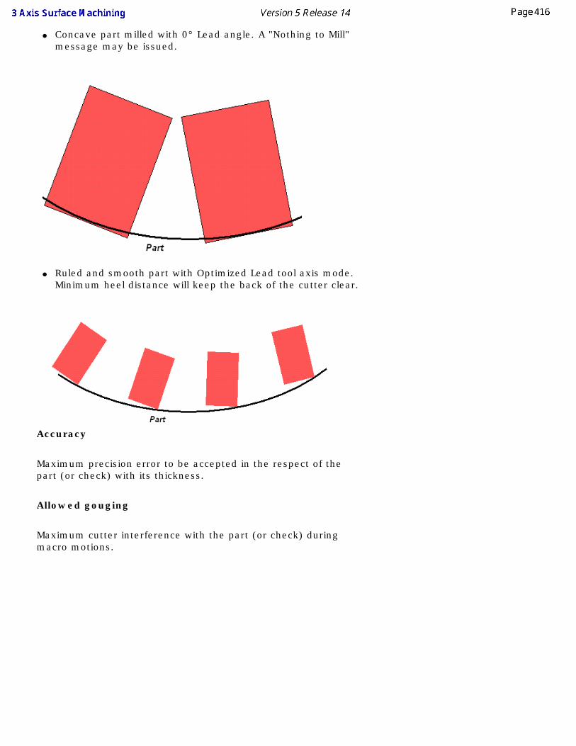
● Concave part milled with 0° Lead angle. A "Nothing to Mill" message may be issued.
● Ruled and smooth part with Optimized Lead tool axis mode. Minimum heel distance will keep the back of the cutter clear.
Accuracy
Maximum precision error to be accepted in the respect of the part (or check) with its thickness.
Allowed gouging
Maximum cutter interference with the part (or check) during macro motions.
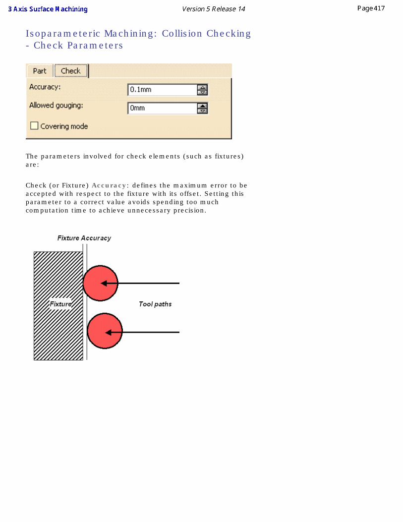
Isoparameteric Machining: Collision Checking - Check Parameters
The parameters involved for check elements (such as fixtures) are:
Check (or Fixture) Accuracy: defines the maximum error to be accepted with respect to the fixture with its offset. Setting this parameter to a correct value avoids spending too much computation time to achieve unnecessary precision.
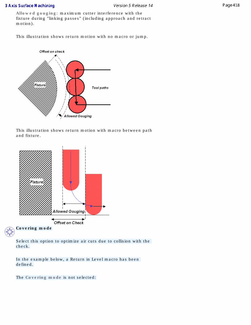
Allowed gouging: maximum cutter interference with the fixture during "linking passes" (including approach and retract motion).
This illustration shows return motion with no macro or jump.
This illustration shows return motion with macro between path and fixture.
Covering mode
Select this option to optimize air cuts due to collision with the check.
In the example below, a Return in Level macro has been defined.
The Covering mode is not selected:
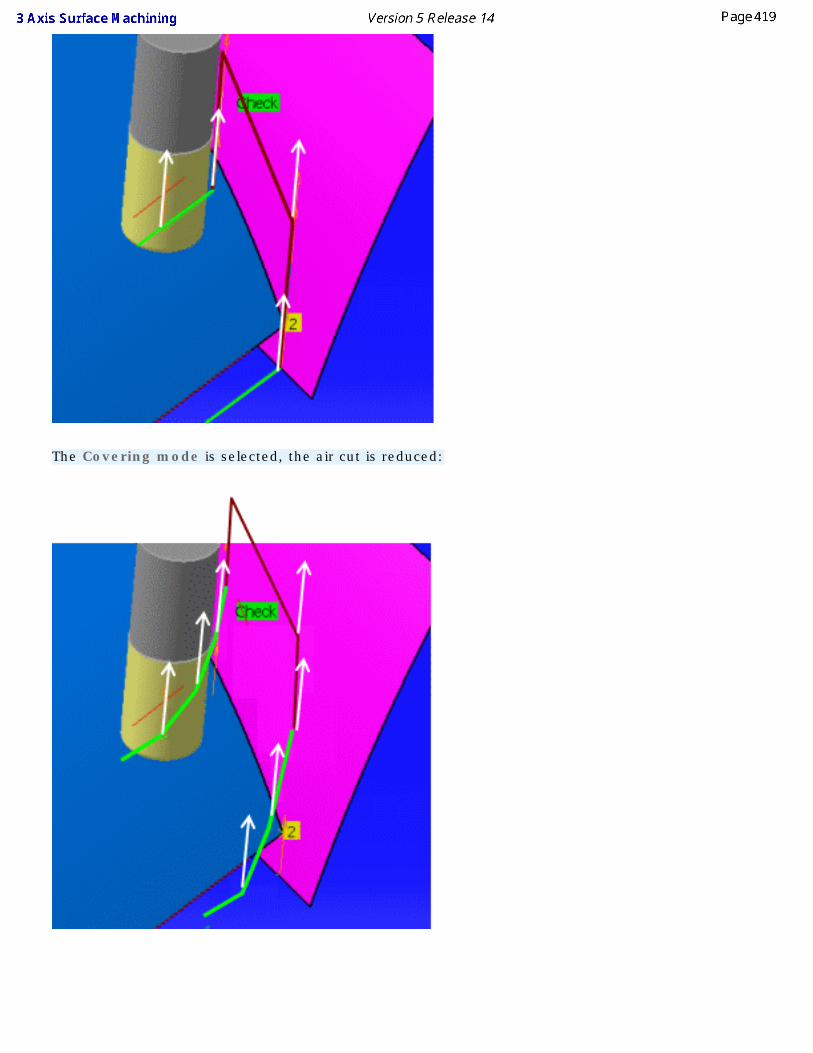
The Covering mode is selected, the air cut is reduced:

● You can apply a positive or negative offset on the check,
● The Covering mode applies to the tool path (in green), not to the macro motions (in red),
● The Covering mode applies to the whole set of check surfaces defined in the machining operation
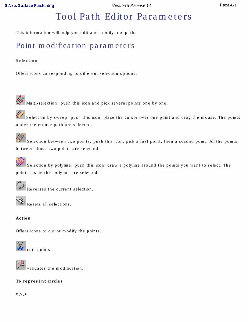
Tool Path Editor ParametersThis information will help you edit and modify tool path.
Point modification parameters
Selection
Offers icons corresponding to different selection options.
Multi-selection: push this icon and pick several points one by one.
Selection by sweep: push this icon, place the cursor over one point and drag the mouse. The points
under the mouse path are selected.
Selection between two points: push this icon, pick a first point, then a second point. All the points
between those two points are selected.
Selection by polyline: push this icon, draw a polyline around the points you want to select. The
points inside this polyline are selected.
Reverses the current selection.
Resets all selections.
Action
Offers icons to cut or modify the points.
cuts points.
validates the modification.
To represent circles
x,y,z
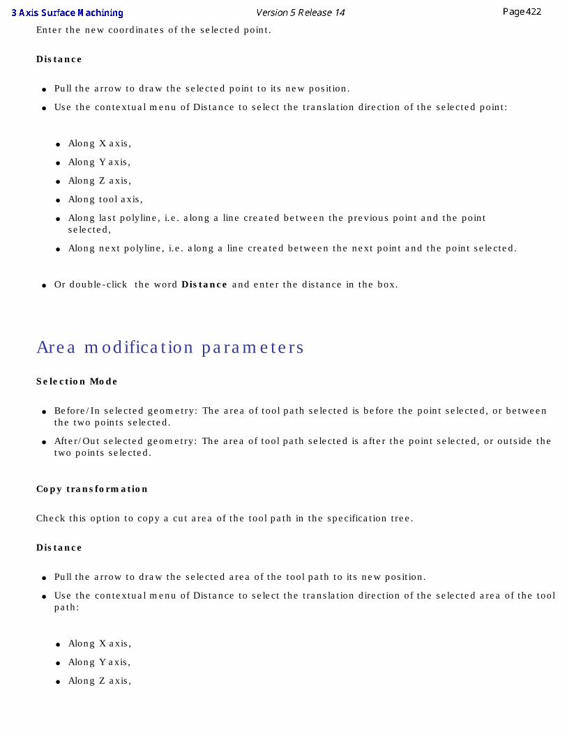
Enter the new coordinates of the selected point.
Distance
● Pull the arrow to draw the selected point to its new position.
● Use the contextual menu of Distance to select the translation direction of the selected point:
● Along X axis,
● Along Y axis,
● Along Z axis,
● Along tool axis,
● Along last polyline, i.e. along a line created between the previous point and the point selected,
● Along next polyline, i.e. along a line created between the next point and the point selected.
● Or double-click the word Distance and enter the distance in the box.
Area modification parameters
Selection Mode
● Before/In selected geometry: The area of tool path selected is before the point selected, or between the two points selected.
● After/Out selected geometry: The area of tool path selected is after the point selected, or outside the two points selected.
Copy transformation
Check this option to copy a cut area of the tool path in the specification tree.
Distance
● Pull the arrow to draw the selected area of the tool path to its new position.
● Use the contextual menu of Distance to select the translation direction of the selected area of the tool path:
● Along X axis,
● Along Y axis,
● Along Z axis,
● Along tool axis.
● Or double-click the word Distance and enter the distance in the box.
Translation parameters
Distance
● Pull the arrow to draw the selected area of the tool path to its new position.
● Use the contextual menu of Distance to select the translation direction of the selected area of the tool path:
● Along X axis,
● Along Y axis,
● Along Z axis,
● Along tool axis.
● Or double-click the word Distance and enter the distance in the box
Rotation parameters
Angle
● Pull the arrow to draw the selected area of the tool path to its new position.
● Use the contextual menu of Angle to select the rotation axis of the selected area of the tool path:
● Rotation around X axis,
● Rotation around Y axis,
● Rotation around Z axis,
● Rotation around tool axis.
● Or double-click the word Angle and enter the angle in the box
Connect parameters
Selection
Offers icons corresponding to different selection options.
Multi-selection: push this icon and pick several points one by one.
Selection by sweep: push this icon, place the cursor over one point and drag the mouse. The points
under the mouse path are selected.
Selection between two points: push this icon, pick a first point, then a second point. All the points
between those two points are selected.
Selection by polyline: push this icon, draw a polyline around the points you want to select. The
points inside this polyline are selected.
Reverses the current selection.
Resets all selections.
Connection mode
Connects points directly
Connects points through a plane
Connects points through the safety plane of the operation.
Distance
Defines the distance the tool will rise to.
X, Y, Z and Nx, Ny, Nz
Define the safety plane through a point and a normal. The connection will go through the point in the plane.
Change approach and retract parameters
Delete
Filter
Check the type of the path you want to delete:
● Approach
● Retract
● Linking passes
● Between paths
You can select several types.
Remove from whole tool path
The action takes the whole tool path into account.
Remove from area inside polygon
The action takes only the selected portion of the tool path into account. You select this portion by drawing a polygon on the tool path.
Add/Modify
Selection
Offers icons corresponding to different selection options.
Multi-selection: push this icon and pick several points one by one.
Selection by sweep: push this icon, place the cursor over one point and drag the mouse. The points
under the mouse path are selected.
Selection between two points: push this icon, pick a first point, then a second point. All the points
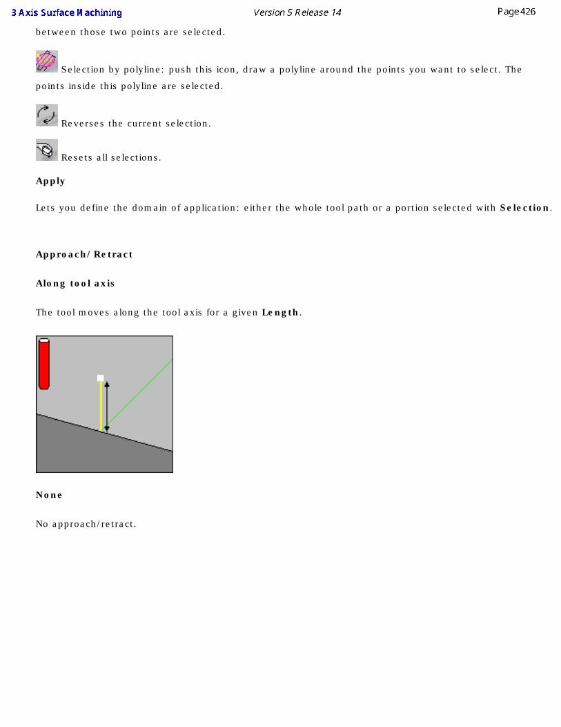
between those two points are selected.
Selection by polyline: push this icon, draw a polyline around the points you want to select. The
points inside this polyline are selected.
Reverses the current selection.
Resets all selections.
Apply
Lets you define the domain of application: either the whole tool path or a portion selected with Selection.
Approach/Retract
Along tool axis
The tool moves along the tool axis for a given Length.
None
No approach/retract.
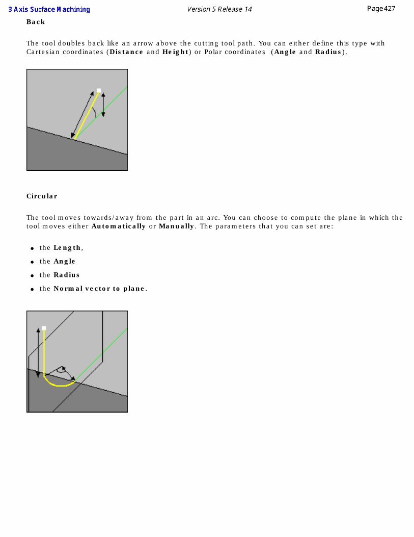
Back
The tool doubles back like an arrow above the cutting tool path. You can either define this type with Cartesian coordinates (Distance and Height) or Polar coordinates (Angle and Radius).
Circular
The tool moves towards/away from the part in an arc. You can choose to compute the plane in which the tool moves either Automatically or Manually. The parameters that you can set are:
● the Length,
● the Angle
● the Radius
● the Normal vector to plane.
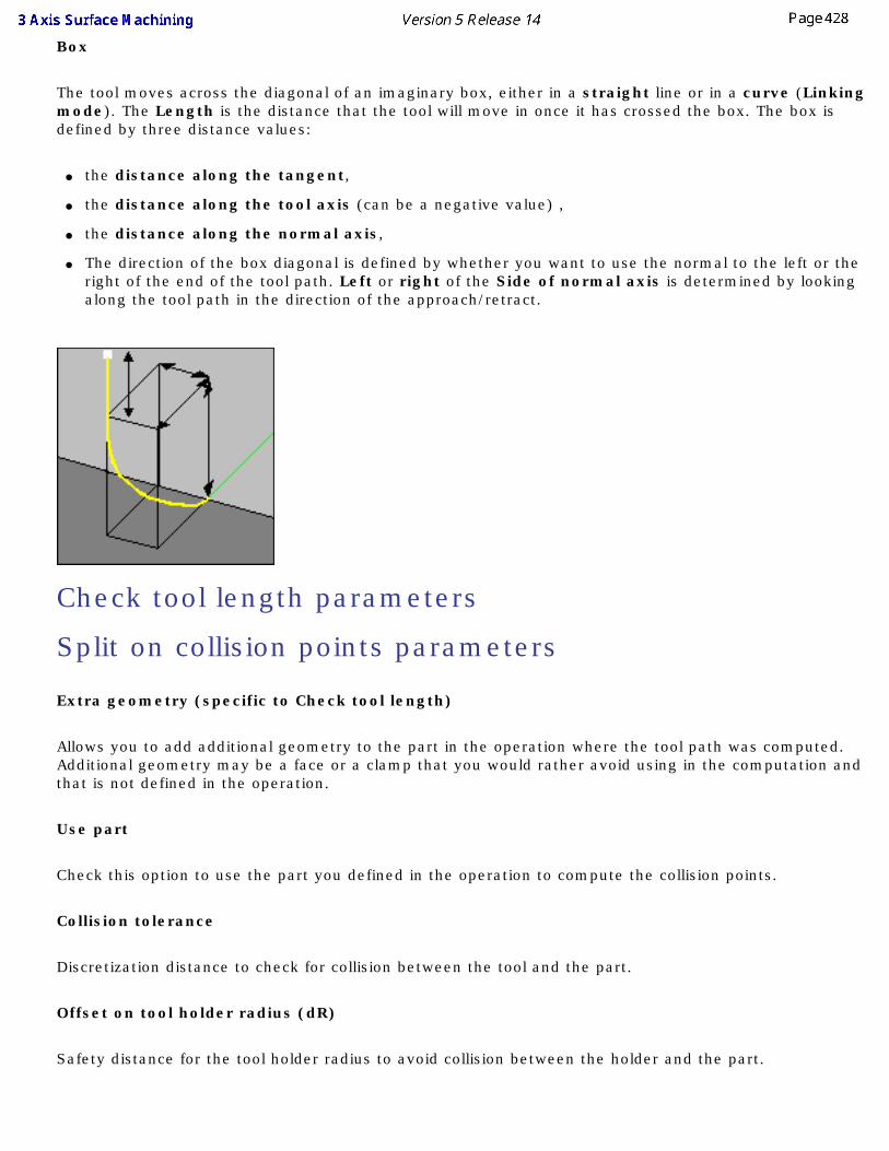
Box
The tool moves across the diagonal of an imaginary box, either in a straight line or in a curve (Linking mode). The Length is the distance that the tool will move in once it has crossed the box. The box is defined by three distance values:
● the distance along the tangent,
● the distance along the tool axis (can be a negative value) ,
● the distance along the normal axis,
● The direction of the box diagonal is defined by whether you want to use the normal to the left or the right of the end of the tool path. Left or right of the Side of normal axis is determined by looking along the tool path in the direction of the approach/retract.
Check tool length parameters
Split on collision points parameters
Extra geometry (specific to Check tool length)
Allows you to add additional geometry to the part in the operation where the tool path was computed. Additional geometry may be a face or a clamp that you would rather avoid using in the computation and that is not defined in the operation.
Use part
Check this option to use the part you defined in the operation to compute the collision points.
Collision tolerance
Discretization distance to check for collision between the tool and the part.
Offset on tool holder radius (dR)
Safety distance for the tool holder radius to avoid collision between the holder and the part.
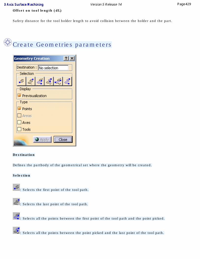
Offset on tool length (dL)
Safety distance for the tool holder length to avoid collision between the holder and the part.
Create Geometries parameters
Destination
Defines the partbody of the geometrical set where the geometry will be created.
Selection
: Selects the first point of the tool path.
: Selects the last point of the tool path.
: Selects all the points between the first point of the tool path and the point picked.
: Selects all the points between the point picked and the last point of the tool path.
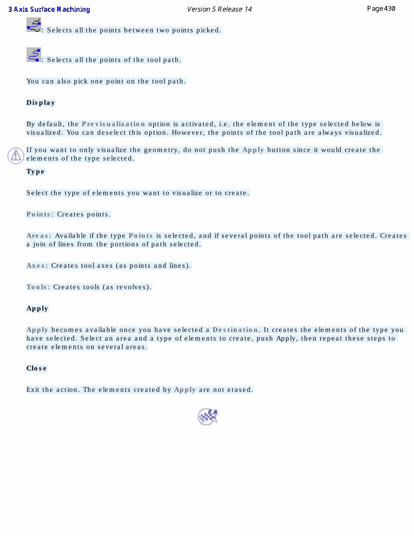
: Selects all the points between two points picked.
: Selects all the points of the tool path.
You can also pick one point on the tool path.
Display
By default, the Previsualization option is activated, i.e. the element of the type selected below is visualized. You can deselect this option. However, the points of the tool path are always visualized.
If you want to only visualize the geometry, do not push the Apply button since it would create the elements of the type selected.
Type
Select the type of elements you want to visualize or to create.
Points: Creates points.
Areas: Available if the type Points is selected, and if several points of the tool path are selected. Creates a join of lines from the portions of path selected.
Axes: Creates tool axes (as points and lines).
Tools: Creates tools (as revolves).
Apply
Apply becomes available once you have selected a Destination. It creates the elements of the type you have selected. Select an area and a type of elements to create, push Apply, then repeat these steps to create elements on several areas.
Close
Exit the action. The elements created by Apply are not erased.
Machining/Slope Areas ParametersThe information in this section will help you create and edit a machining areas and slope areas.
Machining and Slope areas can be used to define different zones on a part. First you define the Machining/Slope areas and then you assign an operation to each of them. This is a useful approach if, before you start machining, you are aware that the part has areas that will require different types of operation.
Another feature of machining areas is their ability to be divided into horizontal, vertical and sloping areas and have operations assigned to these areas.
Select the Machining/Slope area icon , then the geometry of the part to machine in the Geometry tab.
The Slope Area option gives access to:
● the Slope Area tab with:
● tool parameters,
● machining parameters,
● angle parameters.
● the Operations tab to assign machining operations to the defined areas.
Main Panel
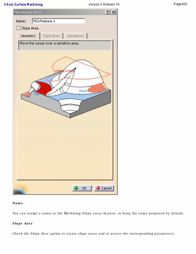
Name
You can assign a name to the Machining/Slope areas feature, or keep the name proposed by default.
Slope Area
Check the Slope Area option to create slope areas and to access the corresponding parameters.
Slope area cannot be used with STL files.
Geometry
With the sensitive icon, you can select the following elements:
● Part.
● Check element. The check is often a clamp that holds the part and therefore is not an area to be machined.
● Area to avoid if you do not wish to machine it (small light brown corner near the red part selection area).
● Limiting contour which is the contour that defines the outer machining limit on the part.
A machining area can be:
● the whole part (for example, in roughing),
● a subset of the faces on the part,
● a subset of faces on the part with a limiting contour.
Slope Area tab
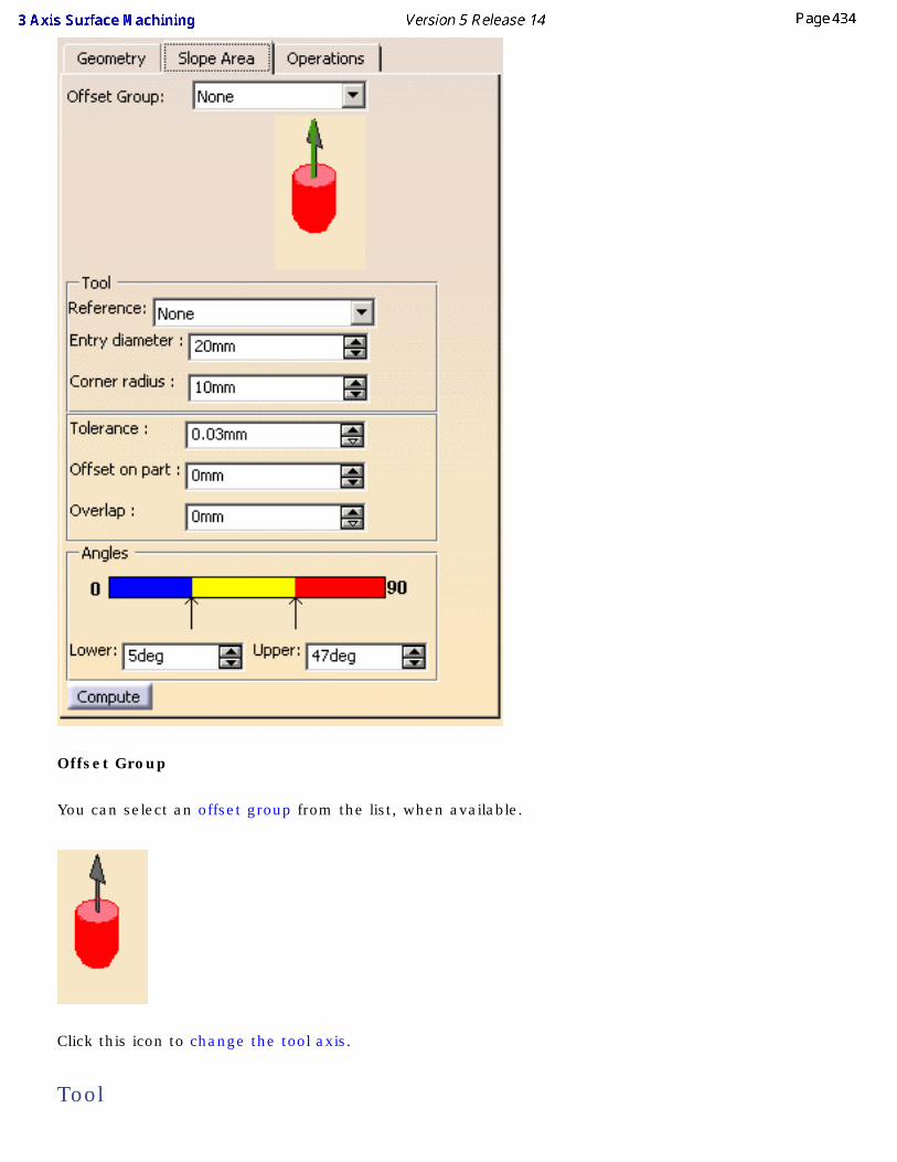
Offset Group
You can select an offset group from the list, when available.
Click this icon to change the tool axis.
Tool
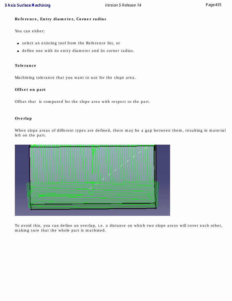
Reference, Entry diameter, Corner radius
You can either:
● select an existing tool from the Reference list, or
● define one with its entry diameter and its corner radius.
Tolerance
Machining tolerance that you want to use for the slope area.
Offset on part
Offset that is computed for the slope area with respect to the part.
Overlap
When slope areas of different types are defined, there may be a gap between them, resulting in material left on the part.
To avoid this, you can define an overlap, i.e. a distance on which two slope areas will cover each other, making sure that the whole part is machined.
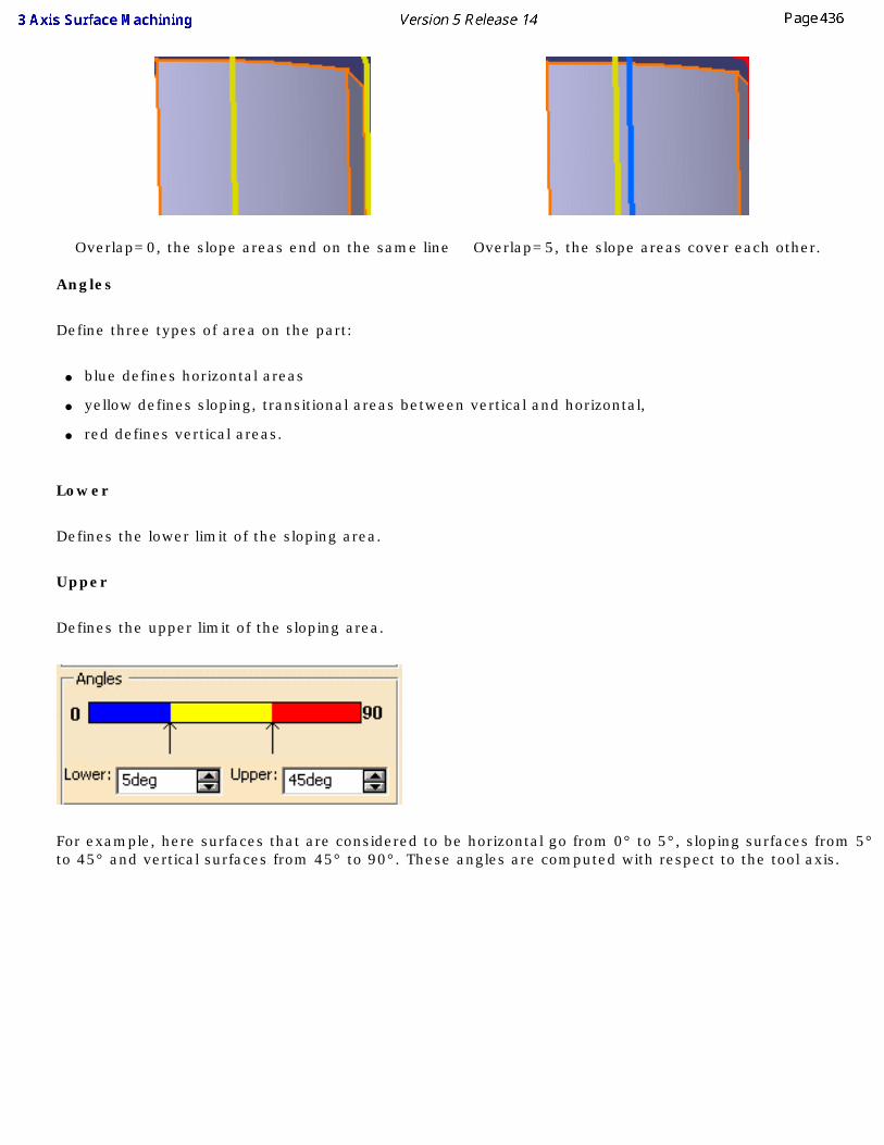
Overlap=0, the slope areas end on the same line Overlap=5, the slope areas cover each other.
Angles
Define three types of area on the part:
● blue defines horizontal areas
● yellow defines sloping, transitional areas between vertical and horizontal,
● red defines vertical areas.
Lower
Defines the lower limit of the sloping area.
Upper
Defines the upper limit of the sloping area.
For example, here surfaces that are considered to be horizontal go from 0° to 5°, sloping surfaces from 5° to 45° and vertical surfaces from 45° to 90°. These angles are computed with respect to the tool axis.
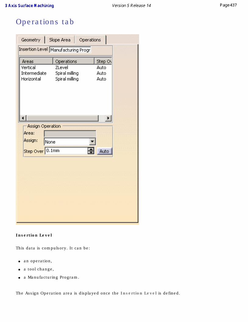
Operations tab
Insertion Level
This data is compulsory. It can be:
● an operation,
● a tool change,
● a Manufacturing Program.
The Assign Operation area is displayed once the Insertion Level is defined.
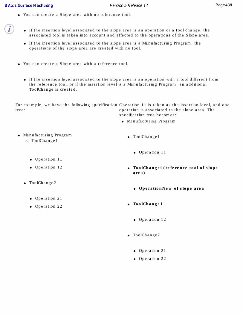
● You can create a Slope area with no reference tool.
● If the insertion level associated to the slope area is an operation or a tool change, the associated tool is taken into account and affected to the operations of the Slope area.
● If the insertion level associated to the slope area is a Manufacturing Program, the operations of the slope area are created with no tool.
● You can create a Slope area with a reference tool.
● If the insertion level associated to the slope area is an operation with a tool different from the reference tool, or if the insertion level is a Manufacturing Program, an additional ToolChange is created.
For example, we have the following specification tree:
● Manufacturing Program ❍ ToolChange1
● Operation 11
● Operation 12
● ToolChange2
● Operation 21
● Operation 22
Operation 11 is taken as the insertion level, and one operation is associated to the slope area. The specification tree becomes:
● Manufacturing Program
● ToolChange1
● Operation 11
● ToolChangei (reference tool of slope area)
● OperationNew of slope area
● ToolChange1'
● Operation 12
● ToolChange2
● Operation 21
● Operation 22
Areas, Operations, Step over, Assign Operation
Used to assign an operation to the machining/slope areas.
● To do so, select one area to which you want to assign an operation and define the operation parameter in the Assign Operation box that is now available.
● Use the Assign combo to select one type of operation, set the Step Over value in the field below.
● To revert to an automatic step over, push the Auto button. The value is replaced with the label Auto.
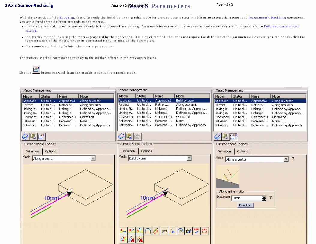
Macro Parameters With the exception of the Roughing, that offers only the Build by user graphic mode for pre-and post-macros in addition to automatic macros, and Isoparametric Machining operations,
you are offered three different methods to add macros:● the catalog method, by using macros already built and stored in a catalog. For more information on how to save or load an existing macro, please refer to Build and use a macros
catalog.
● the graphic method, by using the macros proposed by the application. It is a quick method, that does not require the definition of the parameters. However, you can double-click the representation of the macro, or use its contextual menu, to tune up the parameters.
● the numeric method, by defining the macros parameters.
The numeric method corresponds roughly to the method offered in the previous releases.
Use the button to switch from the graphic mode to the numeric mode.
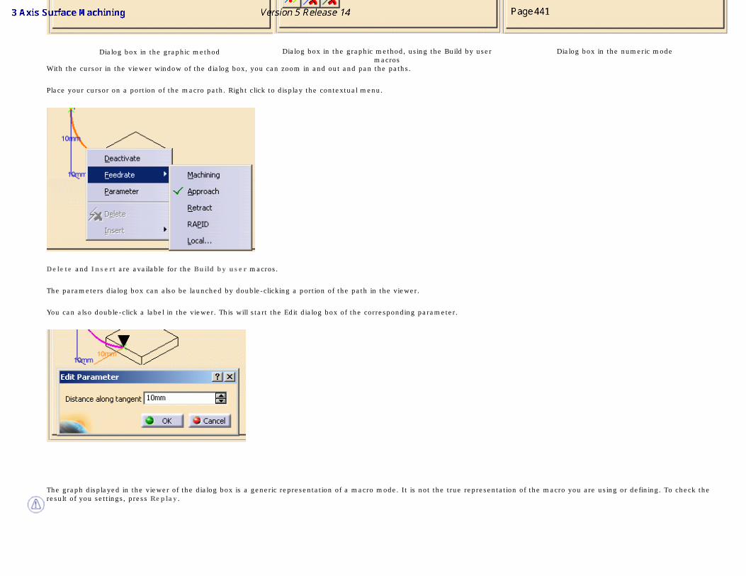
Dialog box in the graphic method Dialog box in the graphic method, using the Build by user macros
Dialog box in the numeric mode
With the cursor in the viewer window of the dialog box, you can zoom in and out and pan the paths.
Place your cursor on a portion of the macro path. Right click to display the contextual menu.
Delete and Insert are available for the Build by user macros.
The parameters dialog box can also be launched by double-clicking a portion of the path in the viewer.
You can also double-click a label in the viewer. This will start the Edit dialog box of the corresponding parameter.
The graph displayed in the viewer of the dialog box is a generic representation of a macro mode. It is not the true representation of the macro you are using or defining. To check the result of you settings, press Replay.
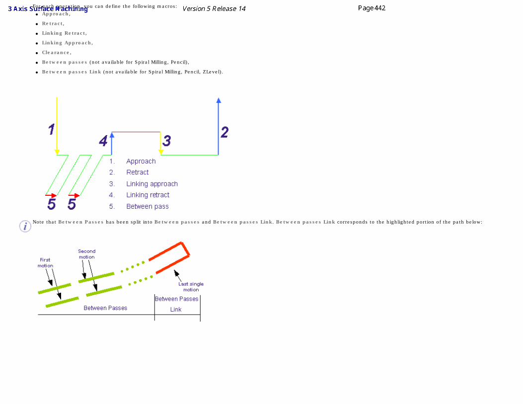
For each operation, you can define the following macros:● Approach,
● Retract,
● Linking Retract,
● Linking Approach,
● Clearance,
● Between passes (not available for Spiral Milling, Pencil),
● Between passes Link (not available for Spiral Milling, Pencil, ZLevel).
Note that Between Passes has been split into Between passes and Between passes Link. Between passes Link corresponds to the highlighted portion of the path below:
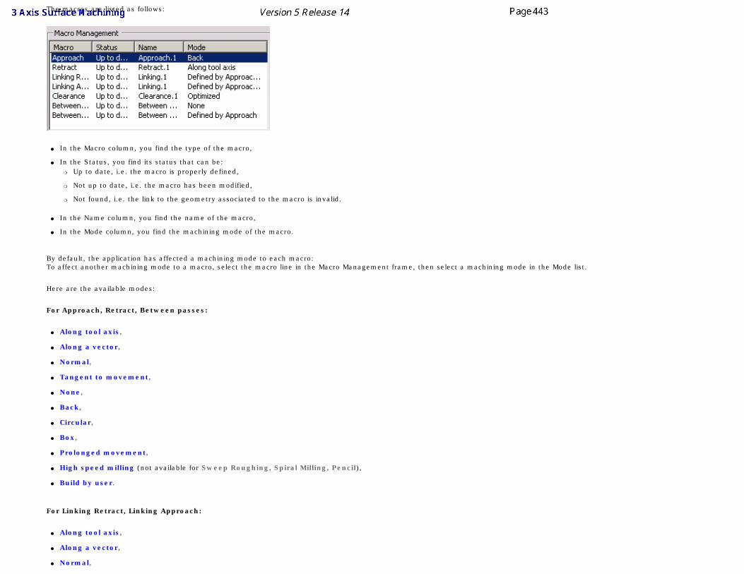
The macros are listed as follows:
● In the Macro column, you find the type of the macro,
● In the Status, you find its status that can be:❍ Up to date, i.e. the macro is properly defined,
❍ Not up to date, i.e. the macro has been modified,
❍ Not found, i.e. the link to the geometry associated to the macro is invalid.
● In the Name column, you find the name of the macro,
● In the Mode column, you find the machining mode of the macro.
By default, the application has affected a machining mode to each macro:To affect another machining mode to a macro, select the macro line in the Macro Management frame, then select a machining mode in the Mode list.
Here are the available modes:
For Approach, Retract, Between passes:
● Along tool axis,
● Along a vector,
● Normal,
● Tangent to movement,
● None,
● Back,
● Circular,
● Box,
● Prolonged movement,
● High speed milling (not available for Sweep Roughing, Spiral Milling, Pencil),
● Build by user.
For Linking Retract, Linking Approach:
● Along tool axis,
● Along a vector,
● Normal,
● Tangent to movement,
● None,
● Back,
● Circular,
● Box,
● Prolonged movement,
● High speed milling (not available for Sweep Roughing, Pencil),
● Defined by Approach/Retract,
● Build by user.
For Clearance:
● Optimized,
● Along tool axis,
● Perpendicular to safety plane (not available for ZLevel).
For Between passes Link (not available for Pencil):
● Straight,
● High speed milling (not available for Sweep Roughing),
● Prolonged movement,
● Defined by Approach.
Note that the Circular macro corresponds to the former one, with an automatic definition of the plane, while Add circular within a plane motion correspond to the former one, with a manual definition of the plane.
To avoid inconsistencies, ZLevel operations offer only the relevant macros:
● Approach,
● Retract,
● Linking Retract,
● Linking Approach,
● Clearance,
● Between passes,
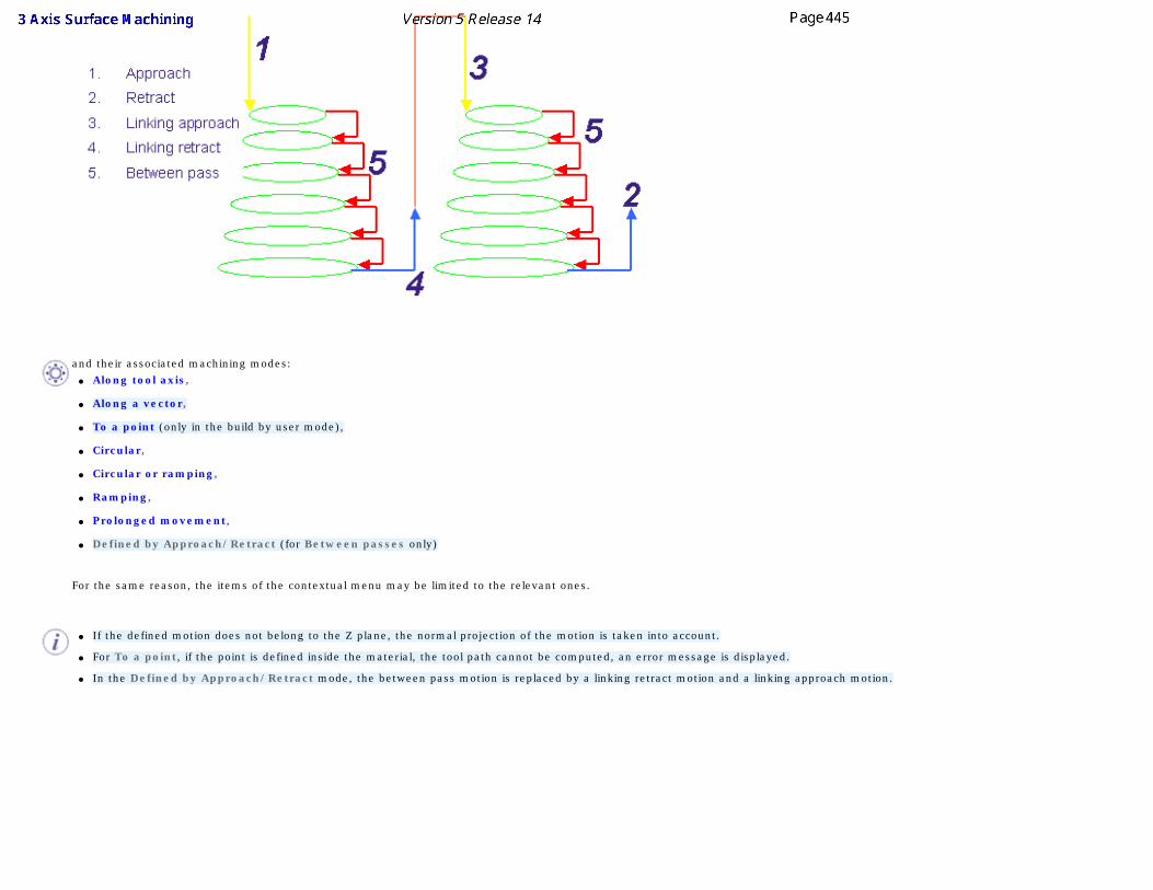
and their associated machining modes:
● Along tool axis,
● Along a vector,
● To a point (only in the build by user mode),
● Circular,
● Circular or ramping,
● Ramping,
● Prolonged movement,
● Defined by Approach/Retract (for Between passes only)
For the same reason, the items of the contextual menu may be limited to the relevant ones.
● If the defined motion does not belong to the Z plane, the normal projection of the motion is taken into account.
● For To a point, if the point is defined inside the material, the tool path cannot be computed, an error message is displayed.
● In the Defined by Approach/Retract mode, the between pass motion is replaced by a linking retract motion and a linking approach motion.
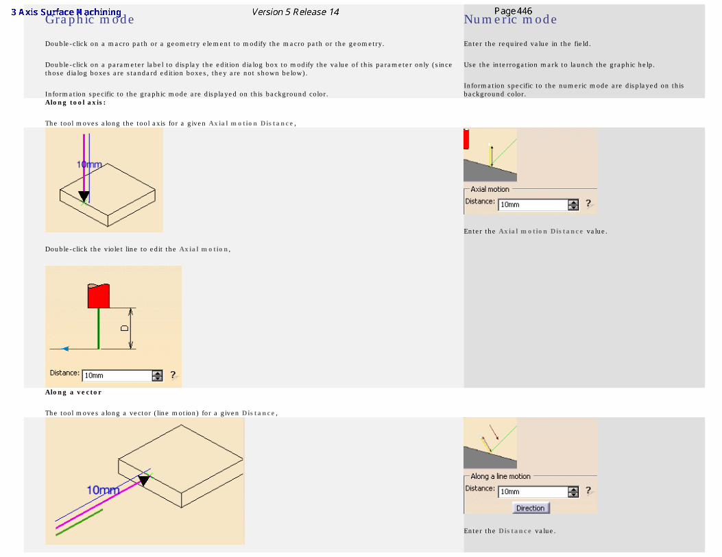
Graphic mode
Double-click on a macro path or a geometry element to modify the macro path or the geometry.
Double-click on a parameter label to display the edition dialog box to modify the value of this parameter only (since those dialog boxes are standard edition boxes, they are not shown below).
Information specific to the graphic mode are displayed on this background color.
Numeric mode
Enter the required value in the field.
Use the interrogation mark to launch the graphic help.
Information specific to the numeric mode are displayed on this background color.
Along tool axis:
The tool moves along the tool axis for a given Axial motion Distance,
Double-click the violet line to edit the Axial motion,
Enter the Axial motion Distance value.
Along a vector
The tool moves along a vector (line motion) for a given Distance,
Enter the Distance value.
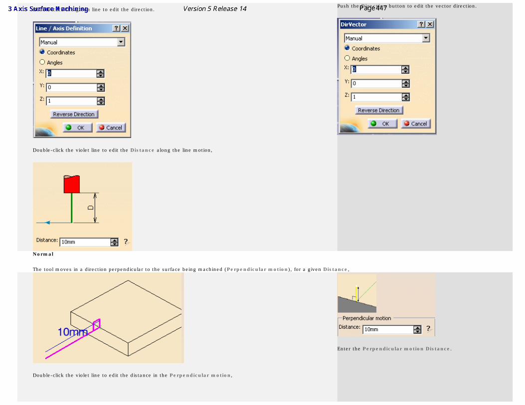
Double-click the green line to edit the direction.
Double-click the violet line to edit the Distance along the line motion,
Push the Direction button to edit the vector direction.
Normal
The tool moves in a direction perpendicular to the surface being machined (Perpendicular motion), for a given Distance,
Double-click the violet line to edit the distance in the Perpendicular motion,
Enter the Perpendicular motion Distance.
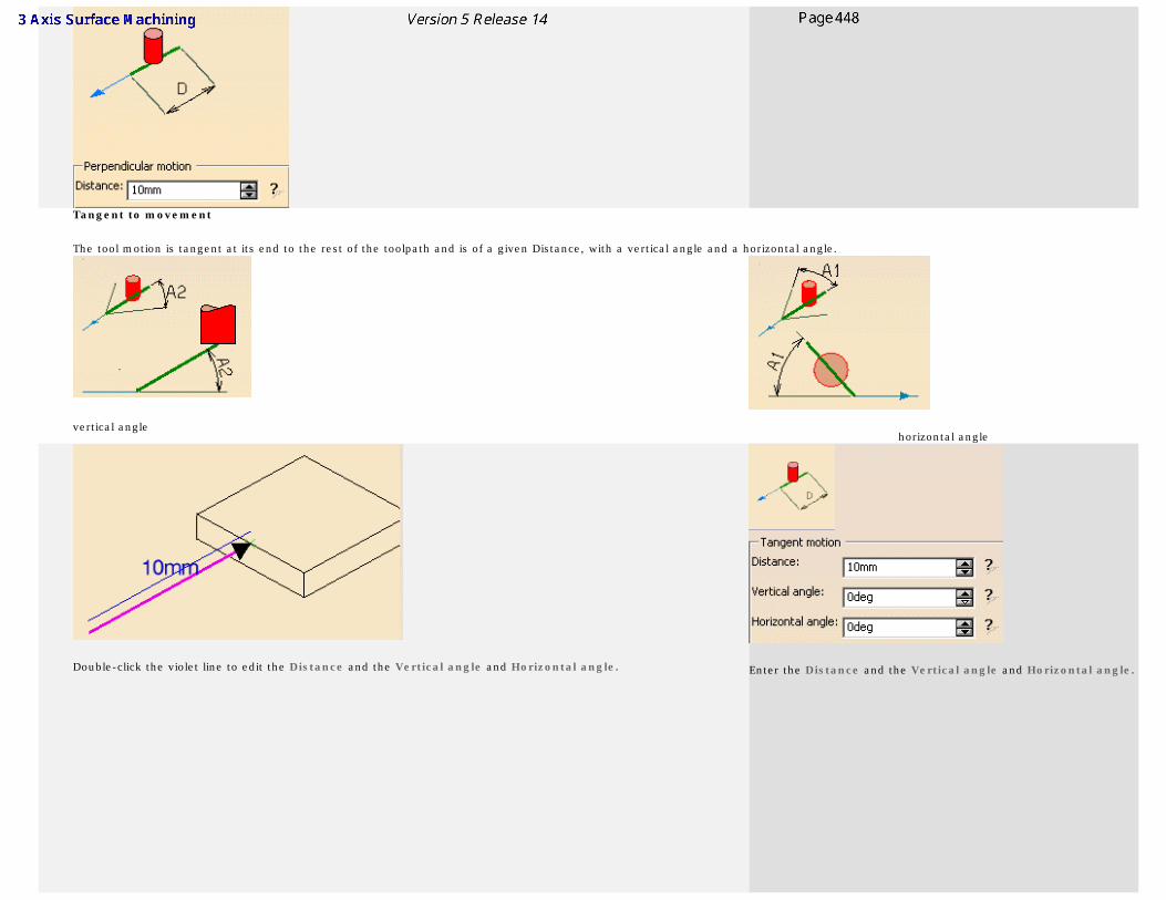
Tangent to movement
The tool motion is tangent at its end to the rest of the toolpath and is of a given Distance, with a vertical angle and a horizontal angle.
vertical anglehorizontal angle
Double-click the violet line to edit the Distance and the Vertical angle and Horizontal angle. Enter the Distance and the Vertical angle and Horizontal angle.
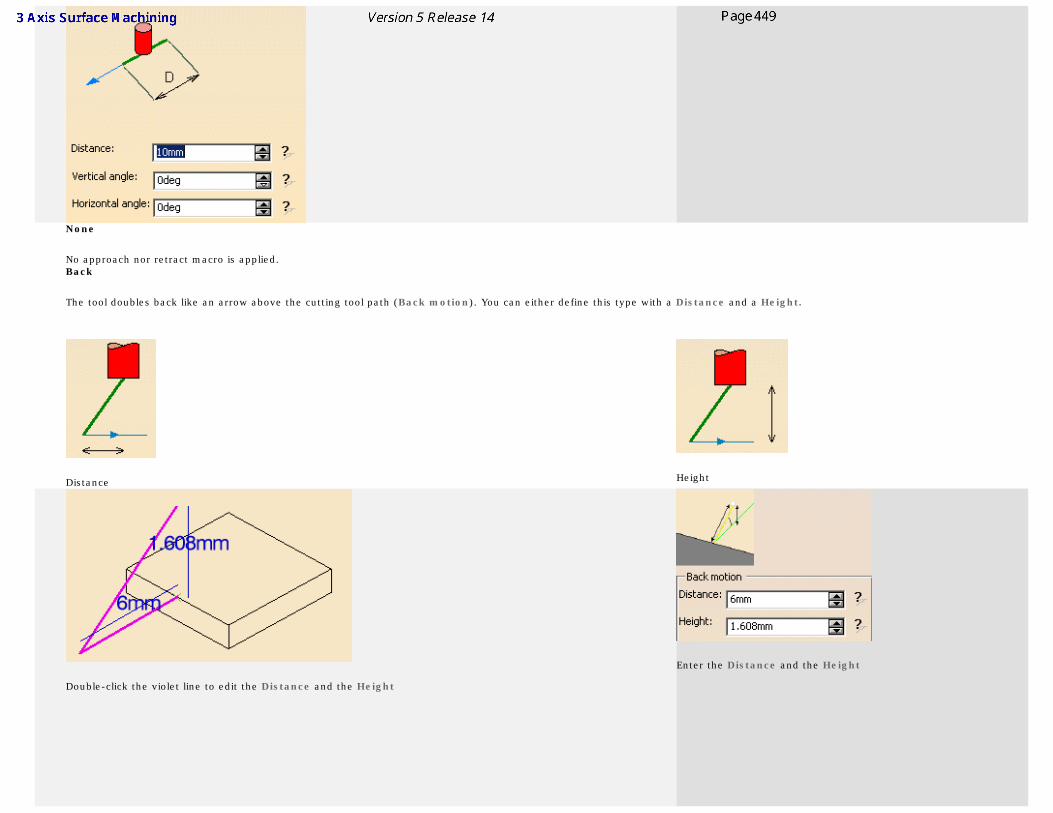
None
No approach nor retract macro is applied. Back
The tool doubles back like an arrow above the cutting tool path (Back motion). You can either define this type with a Distance and a Height.
Distance Height
Double-click the violet line to edit the Distance and the Height
Enter the Distance and the Height
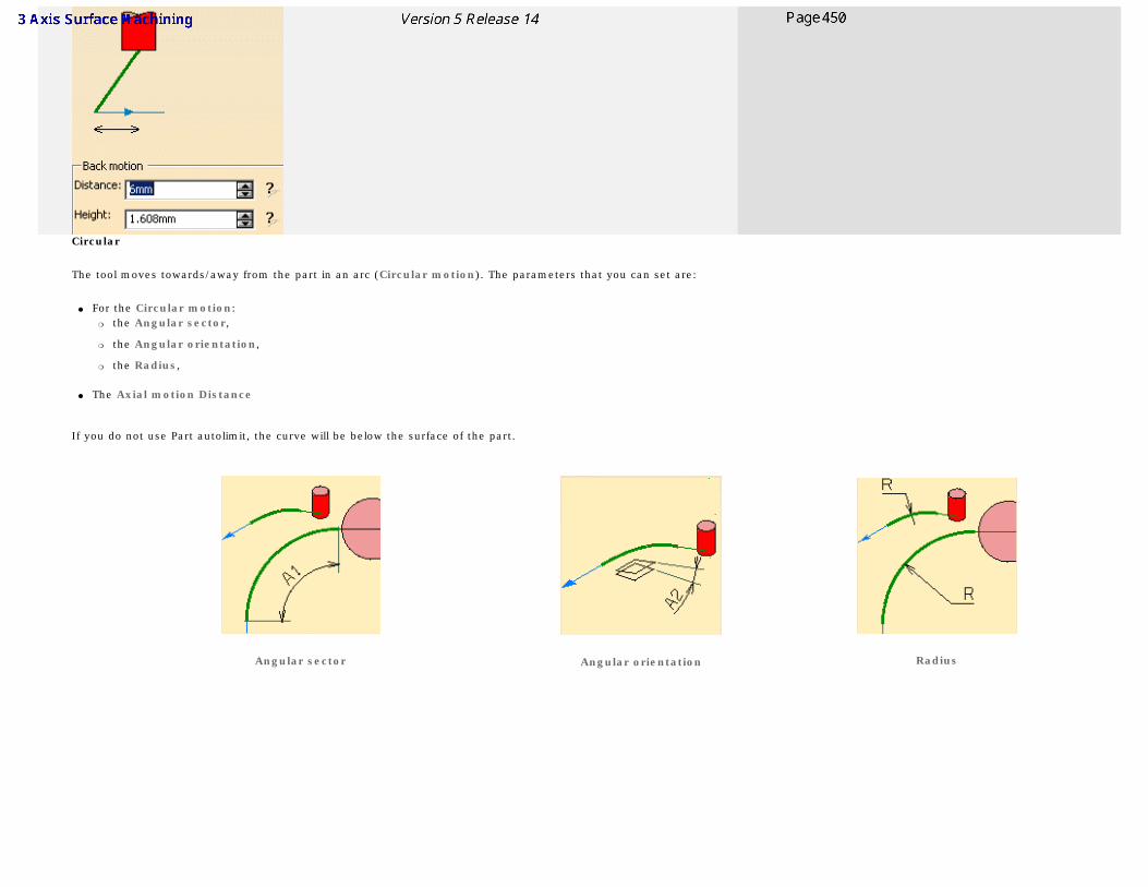
Circular
The tool moves towards/away from the part in an arc (Circular motion). The parameters that you can set are:
● For the Circular motion:❍ the Angular sector,
❍ the Angular orientation,
❍ the Radius,
● The Axial motion Distance
If you do not use Part autolimit, the curve will be below the surface of the part.
Angular sector Angular orientation Radius
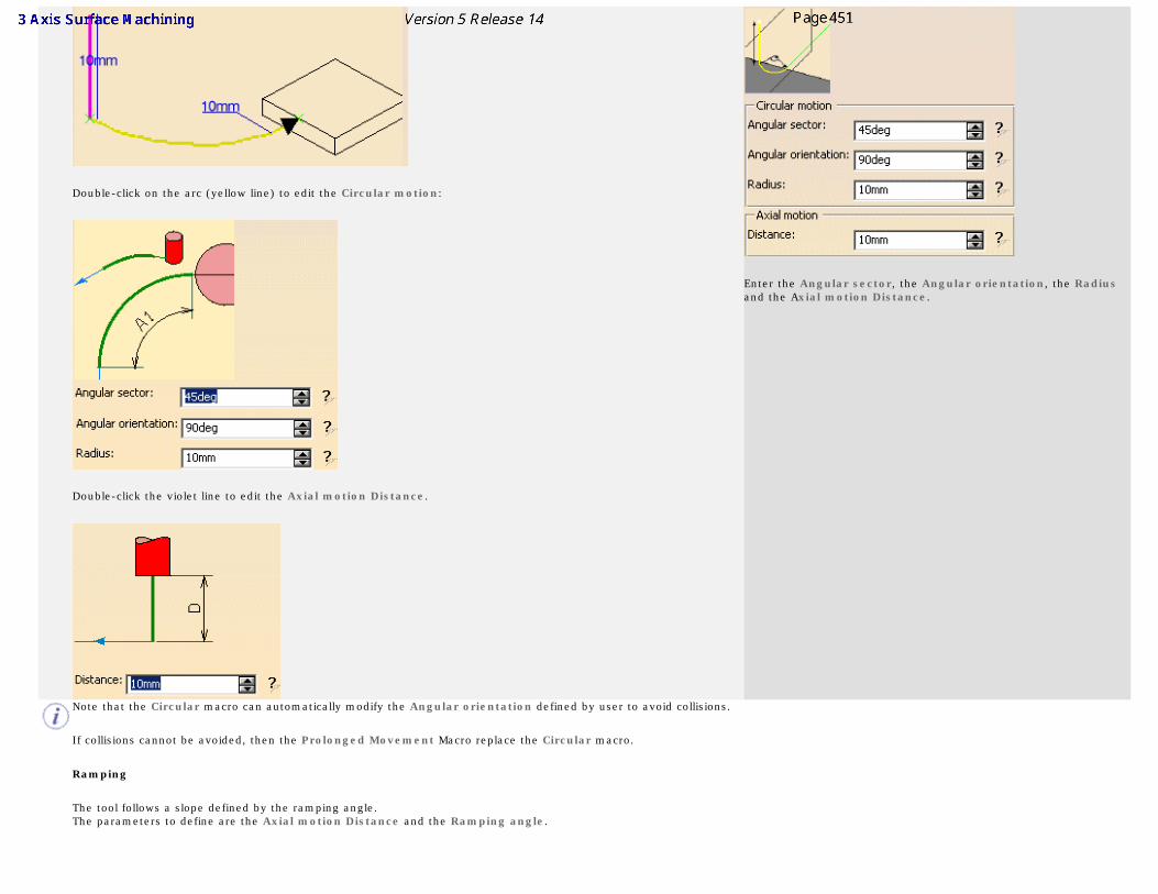
Double-click on the arc (yellow line) to edit the Circular motion:
Double-click the violet line to edit the Axial motion Distance.
Enter the Angular sector, the Angular orientation, the Radius and the Axial motion Distance.
Note that the Circular macro can automatically modify the Angular orientation defined by user to avoid collisions.
If collisions cannot be avoided, then the Prolonged Movement Macro replace the Circular macro.
Ramping
The tool follows a slope defined by the ramping angle. The parameters to define are the Axial motion Distance and the Ramping angle.
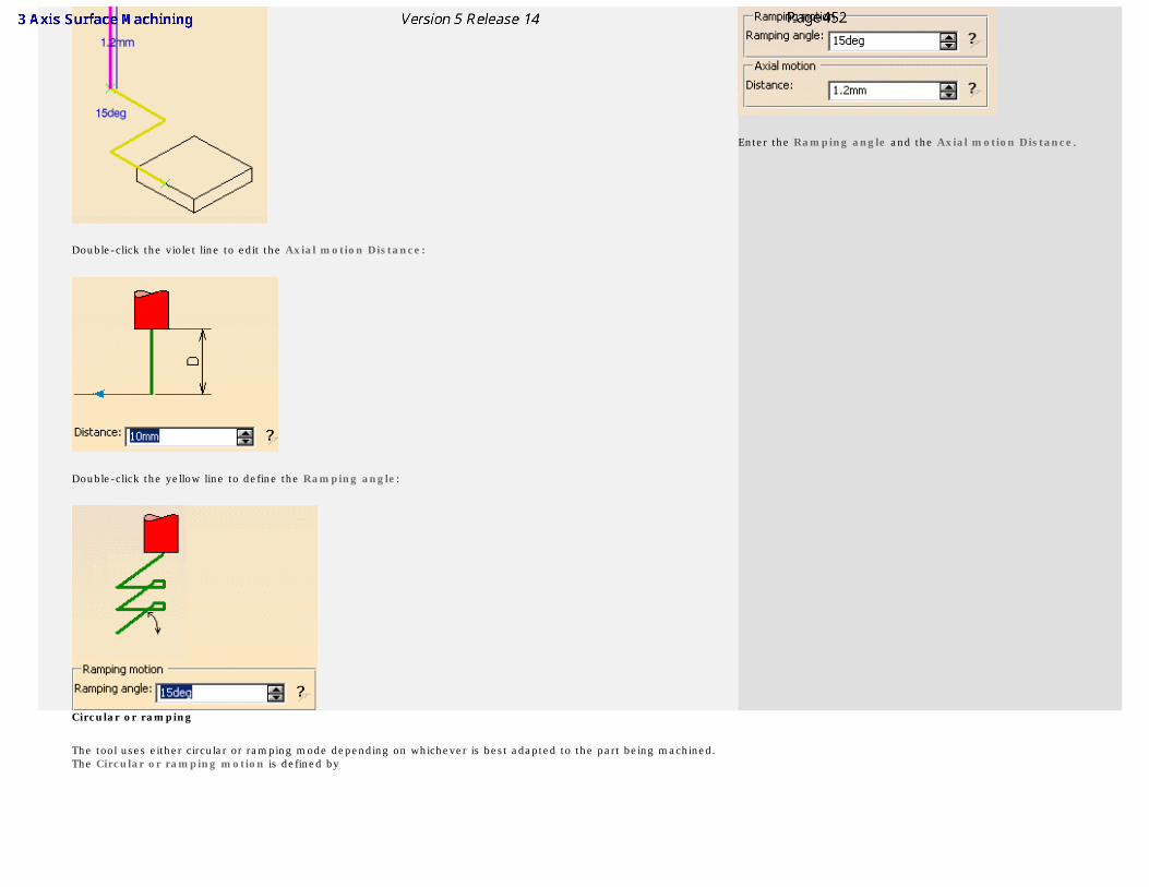
Double-click the violet line to edit the Axial motion Distance:
Double-click the yellow line to define the Ramping angle:
Enter the Ramping angle and the Axial motion Distance.
Circular or ramping
The tool uses either circular or ramping mode depending on whichever is best adapted to the part being machined. The Circular or ramping motion is defined by
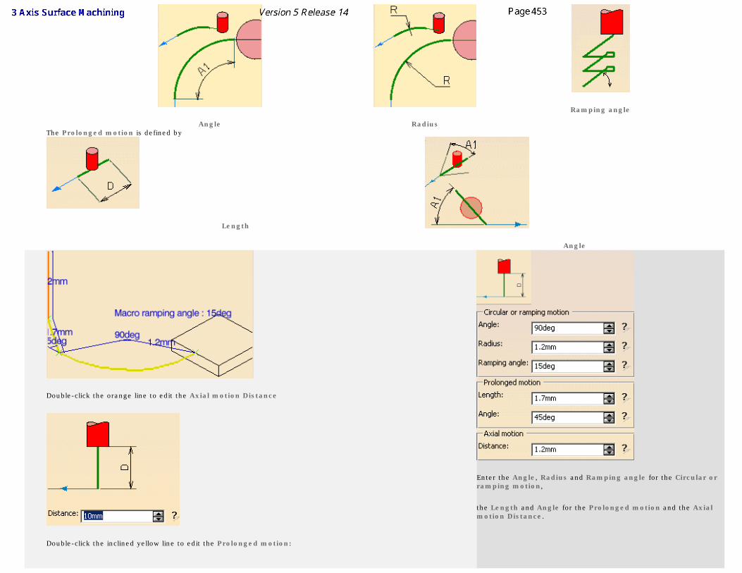
Angle Radius
Ramping angle
The Prolonged motion is defined by
Length
Angle
Double-click the orange line to edit the Axial motion Distance
Double-click the inclined yellow line to edit the Prolonged motion:
Enter the Angle, Radius and Ramping angle for the Circular or ramping motion,
the Length and Angle for the Prolonged motion and the Axial motion Distance.
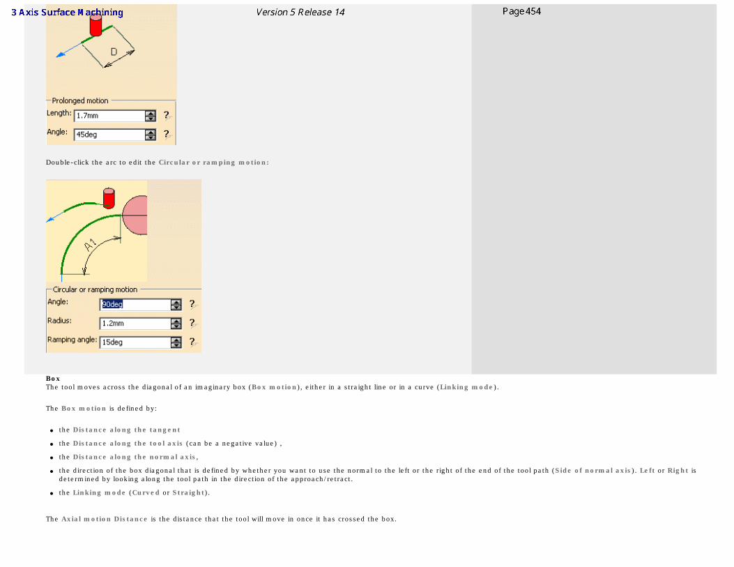
Double-click the arc to edit the Circular or ramping motion:
Box The tool moves across the diagonal of an imaginary box (Box motion), either in a straight line or in a curve (Linking mode).
The Box motion is defined by:
● the Distance along the tangent
● the Distance along the tool axis (can be a negative value) ,
● the Distance along the normal axis,
● the direction of the box diagonal that is defined by whether you want to use the normal to the left or the right of the end of the tool path (Side of normal axis). Left or Right is determined by looking along the tool path in the direction of the approach/retract.
● the Linking mode (Curved or Straight).
The Axial motion Distance is the distance that the tool will move in once it has crossed the box.
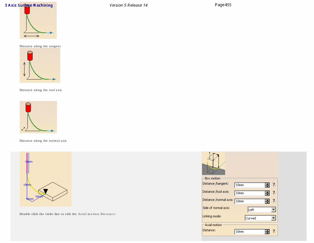
Distance along the tangent
Distance along the tool axis
Distance along the normal axis
Double-click the violet line to edit the Axial motion Distance:
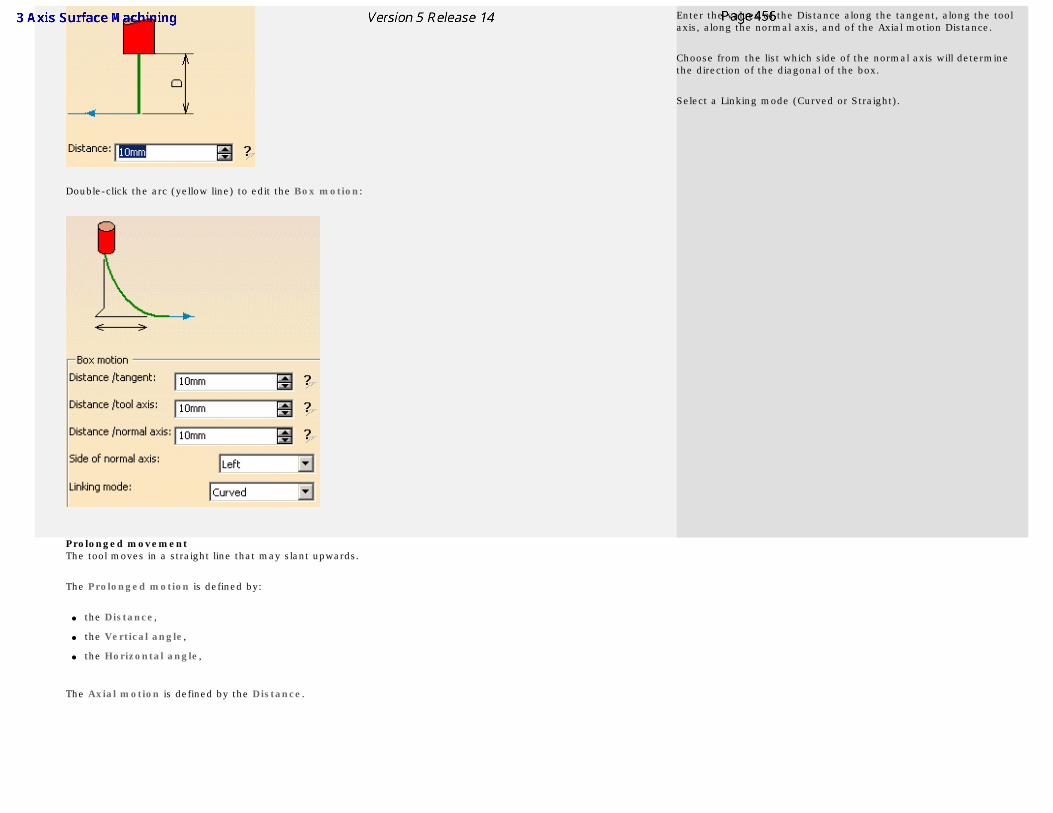
Double-click the arc (yellow line) to edit the Box motion:
Enter the values of the Distance along the tangent, along the tool axis, along the normal axis, and of the Axial motion Distance.
Choose from the list which side of the normal axis will determine the direction of the diagonal of the box.
Select a Linking mode (Curved or Straight).
Prolonged movement The tool moves in a straight line that may slant upwards.
The Prolonged motion is defined by:
● the Distance,
● the Vertical angle,
● the Horizontal angle,
The Axial motion is defined by the Distance.
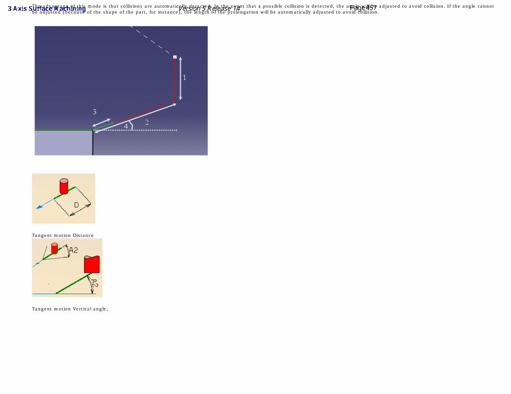
The advantage of this mode is that collisions are automatically detected. In the event that a possible collision is detected, the angle will be adjusted to avoid collision. If the angle cannot be adjusted (because of the shape of the part, for instance), the length of the prolongation will be automatically adjusted to avoid collision.
Tangent motion Distance
Tangent motion Vertical angle,
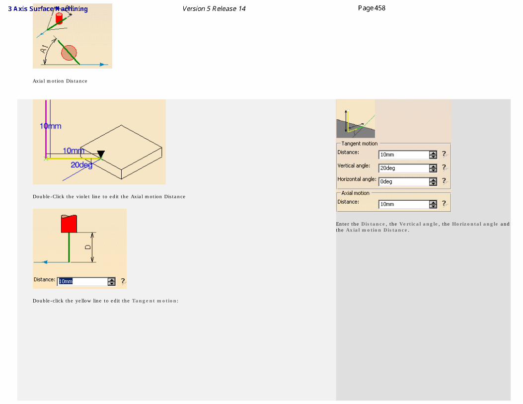
Axial motion Distance
Double-Click the violet line to edit the Axial motion Distance
Double-click the yellow line to edit the Tangent motion:
Enter the Distance, the Vertical angle, the Horizontal angle and the Axial motion Distance.
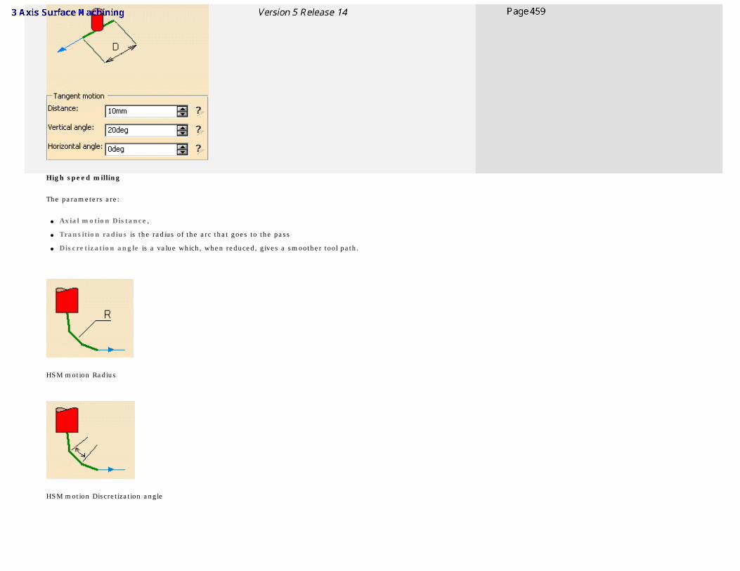
High speed milling
The parameters are:
● Axial motion Distance,
● Transition radius is the radius of the arc that goes to the pass
● Discretization angle is a value which, when reduced, gives a smoother tool path.
HSM motion Radius
HSM motion Discretization angle
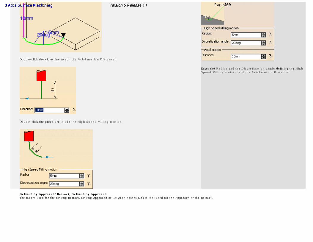
Double-click the violet line to edit the Axial motion Distance:
Double-click the green arc to edit the High Speed Milling motion
Enter the Radius and the Discretization angle defining the High Speed Milling motion, and the Axial motion Distance.
Defined by Approach/Retract, Defined by Approach The macro used for the Linking Retract, Linking Approach or Between passes Link is that used for the Approach or the Retract.
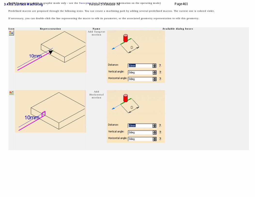
Build by user (available in graphic mode only - see the Sweeping User Task for more information on the operating mode)
Predefined macros are proposed through the following icons. You can create a machining path by adding several predefined macros. The current one is colored violet.
If necessary, you can double-click the line representing the macro to edit its parameter, or the associated geometry representation to edit this geometry.
Icon Representation Name Available dialog boxes
Add Tangent motion
Add
Horizontal motion
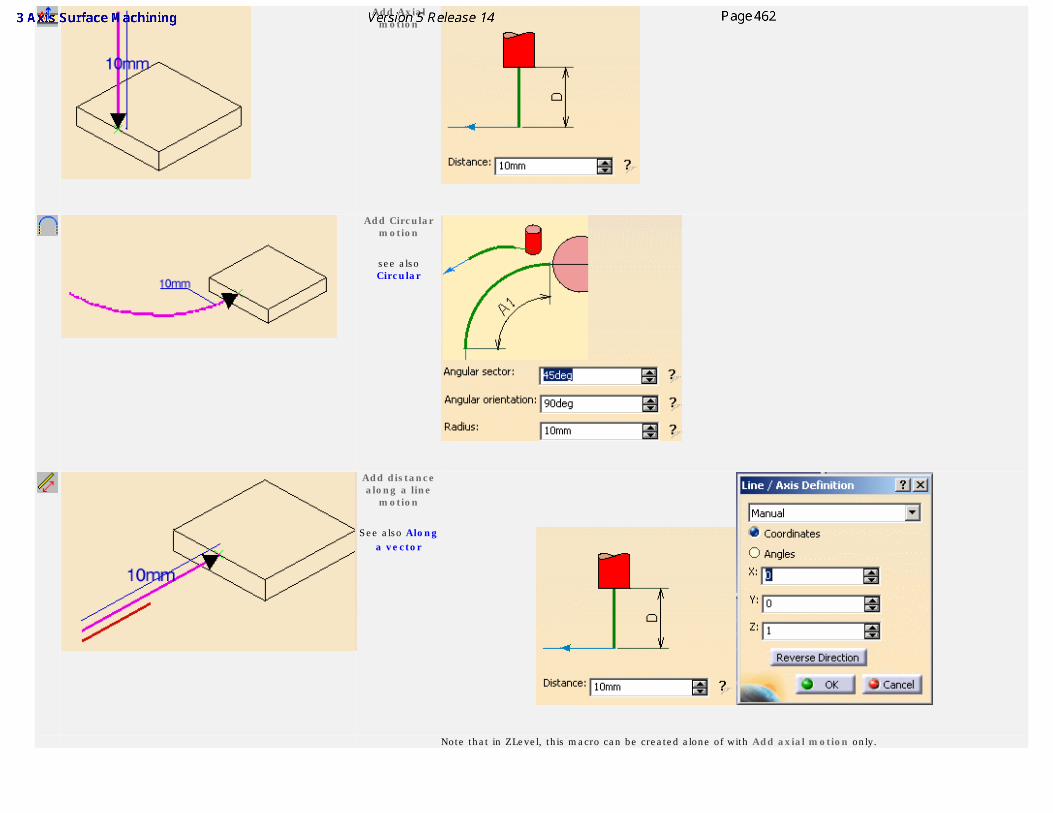
Add Axial motion
Add Circular
motion
see also Circular
Add distance along a line
motion
See also Along a vector
Note that in ZLevel, this macro can be created alone of with Add axial motion only.
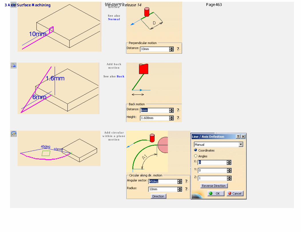
Add normal motion
See also Normal
Add back motion
See also Back
Add circular
within a plane motion
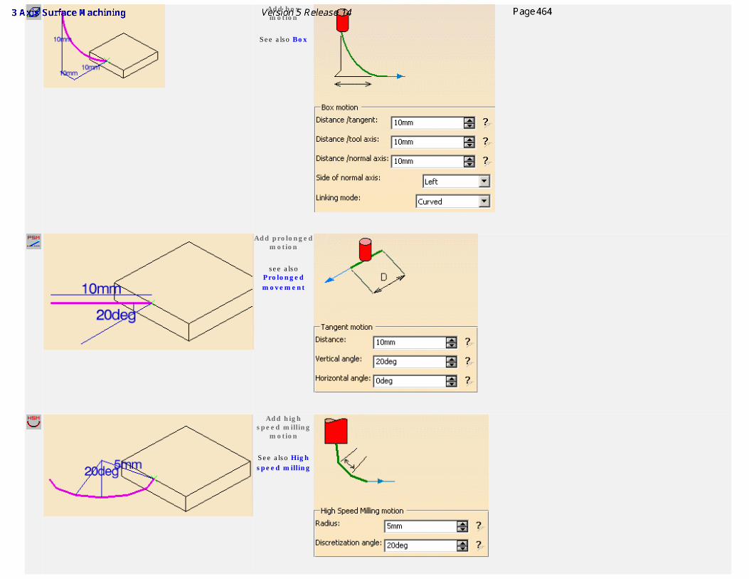
Add box motion
See also Box
Add prolonged
motion
see also Prolonged movement
Add high
speed milling motion
See also High speed milling
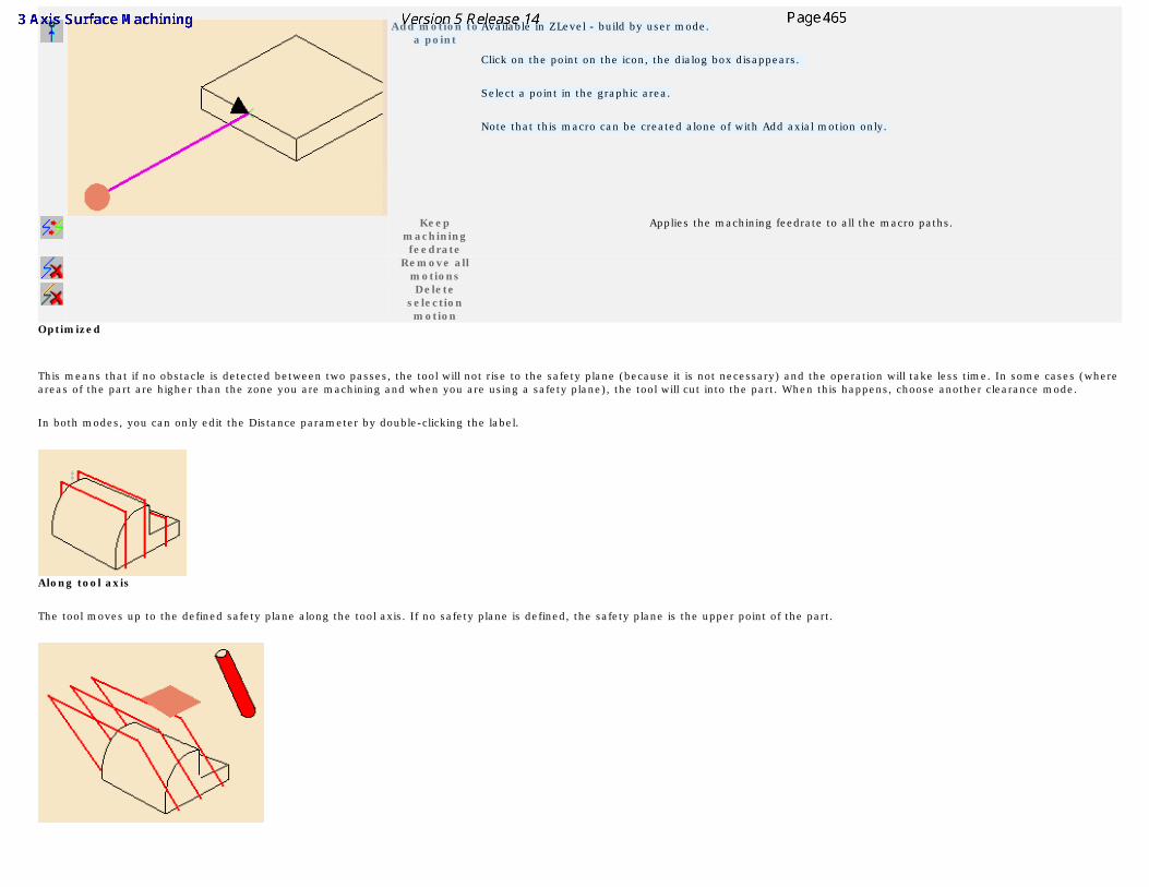
Add motion to
a pointAvailable in ZLevel - build by user mode.
Click on the point on the icon, the dialog box disappears.
Select a point in the graphic area.
Note that this macro can be created alone of with Add axial motion only.
Keep machining feedrate
Applies the machining feedrate to all the macro paths.
Remove all motions
Delete selection motion
Optimized
This means that if no obstacle is detected between two passes, the tool will not rise to the safety plane (because it is not necessary) and the operation will take less time. In some cases (where areas of the part are higher than the zone you are machining and when you are using a safety plane), the tool will cut into the part. When this happens, choose another clearance mode.
In both modes, you can only edit the Distance parameter by double-clicking the label.
Along tool axis
The tool moves up to the defined safety plane along the tool axis. If no safety plane is defined, the safety plane is the upper point of the part.
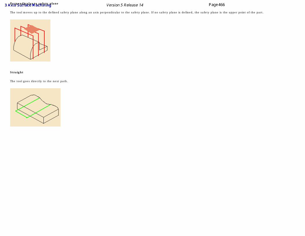
Perpendicular to safety plane
The tool moves up to the defined safety plane along an axis perpendicular to the safety plane. If no safety plane is defined, the safety plane is the upper point of the part.
Straight
The tool goes directly to the next path.
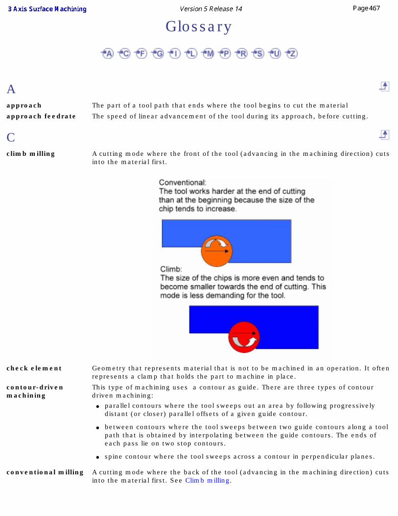
Glossary
Aapproach The part of a tool path that ends where the tool begins to cut the material
approach feedrate The speed of linear advancement of the tool during its approach, before cutting.
Cclimb milling A cutting mode where the front of the tool (advancing in the machining direction) cuts
into the material first.
check element Geometry that represents material that is not to be machined in an operation. It often represents a clamp that holds the part to machine in place.
contour-driven machining
This type of machining uses a contour as guide. There are three types of contour driven machining:
● parallel contours where the tool sweeps out an area by following progressively distant (or closer) parallel offsets of a given guide contour.
● between contours where the tool sweeps between two guide contours along a tool path that is obtained by interpolating between the guide contours. The ends of each pass lie on two stop contours.
● spine contour where the tool sweeps across a contour in perpendicular planes.
conventional milling A cutting mode where the back of the tool (advancing in the machining direction) cuts into the material first. See Climb milling.
cut depth The maximum depth of the cut effected by the tool at each pass.
Ffeedrate The speed of linear advancement of the tool into the material while cutting.
frontal wall An area of the part surface that forms an inclined wall that the advancing tool will climb or descend.
Gguide contour A contour used to guide the tool during an operation.
See Contour-driven machining.
Iimposed plane A plane that the tool must pass through. This option is useful for machining parts that
have grooves or steps and when you want to make sure that these areas are cut.
inner point The point where the tool will start cutting in a roughing operation when the surface to machine has pockets.
Llateral wall An area of the part surface that forms an inclined wall that the tool will advance along
laterally instead of climbing or descending.
limit line A contour that is used to delimit the areas to machine in an operation.
lower plane One of the two planes normal to the tool axis that confines the area to machine. The operation will only machine between this plane and the upper plane.
Mmachining area An area defined on a part either:
● during an operation as part of the machining geometry ,
● or before an operation, the operation being assigned to a machining area afterwards.
A machining area can be:
● the whole part (for example, in roughing),
● a subset of the faces on the part,
● a subset of faces on the part with a limiting contour.
Ppencil operations A pencil operation is one where the tool remains tangent in two places to the surface
to be machined during the cycle. It is often used to remove crests along the intersection of two surfaces that were left behind by a previous operation.
plunge A movement where the tool plunges deeper into the material, advancing along the (negative) tool axis.
pocket An area on a part surface that represents an internal depression (in Z) relative to the surrounding part surfaces. An internal depression is one that does not extend to the outside edge of the part.
P.P.R. Process Product Resources.
Rretract The part of a tool path that begins where the tool stops cutting the material.
rework area An area that cannot be machined with a given tool.
reworking An operation which touches up zones that are left completely unmachined by previous operations.
roughing An operation where a part is rough-machined by horizontal planes.
rough stock The block of raw material to be machined to produce a part.
Ssafety distance A horizontal clearance distance that the tool moves over at the feedrate in order to
disengage the tool from cutting between passes.
scallop height The maximum allowable height of the crests of material left uncut after machining.
spindle speed The speed of the spinning tool around its axis.
start point The point where the tool will start cutting in a roughing operation where the surface to cut is accessed from the outside of the part.
stepover distance The width of the overlap between two successive passes.
stop contours The two contours connecting the ends of two guide contours in contour-driven machining (between contours option). The ends of each pass lie on the stop contours.
sweeping operations Sweeping operations machine the whole part and are used for finishing and semi-finishing work. The tool paths are executed in vertical parallel planes.
sweep roughing An operation where a part is rough-machined by vertical planes.
Uupper plane One of the two planes normal to the tool axis that confines the area to machine. The
operation will only machine between this plane and the lower plane.
ZZLevel machining An operation where the tool progressively follows the part surface at different
constant Z values (heights).
Index
Numerics4 open contours
Contour-driven 4 points on a closed contour
Contour-driven
AAccuracy
Isoparametric Machining Activate
Macros
Tool Gage Activate All
Tool Gage Active
Isoparametric Machining Add Axial motion
Macros Add back motion
Macros Add box motion
Macros Add Circular motion
Macros Add circular within a plane motion
Macros Add distance along a line motion
Macros Add high speed milling motion
Macros Add Horizontal motion
Macros Add normal motion
Macros Add prolonged motion
Macros All
Sweeping Allowed gouging
Isoparametric Machining Along a vector
Macros Along tool axis
Macros
Spiral milling
Sweeping
Tool path editor Always stay on bottom
Roughing Analyze
Macros Angle
Tool path editor Angles
Machining/Slope area Angular orientation
Macros Angular sector
Macros Approach distance
Roughing Approach modes
Roughing Area modification
command Area modification parameters
Tool path editor Area-oriented machining
Getting started
Area-oriented machining methodology Areas
Machining/Slope area Assign operations
Machining/Slope area Automatic horizontal areas detections
Roughing
Automatic rough stock Avoiding
Tool holder collisions Axial direction
Pencil Axial motion Distance
Macros Axial safety distance
Roughing Axial tab
Contour-driven
Pencil
Roughing
Spiral milling
Sweep roughing
Sweeping
ZLevel Axis system
Rough Stock
BBack
Macros
Tool path editor Between Contours
Contour-driven
Bottom tab
Roughing Box
Macros
Tool path editor Box linking mode
Tool path editor Box motion
Macros Build by user
Macros
CCGR as rough stock
Roughing Change approach and retract
command
Tool path editor Change tool axis
Machining/Slope area Changing selection defaults
Tool path editor Check parameters
Isoparametric Machining Check Tool Length
command Check tool length parameters
Tool path editor Circular
Macros
Tool path editor Circular motion
Macros Circular or ramping
Macros
Circular or ramping motion
Macros Clearance along tool axis
Macros Climb
Pencil
ZLevel Collision check
Contour-driven
Isoparametric Machining
Spiral milling
Sweeping Collision Checking - Check
Isoparametric Machining Collision Checking - Part
Isoparametric Machining Collision tolerance
Split on collision points
Tool path editor command
Area modification
Change approach and retract
Check Tool Length
Compute Tool Gage on Assembly
Connection
Contour-driven
Creates a stock by offset
Creates rough stock
Cut an area
Generate Documentation
Generate NC Code in Batch Mode
Geometrical Zone
Import APT, clfile or NC Code file
Insert an STL file
Isoparametric Machining
Limit Lines Creation Wizard
Limit Lines Projection Wizard
Machining View
Machining/Slope Area
Mirror
Offset Group
Pack Tool Path
Pencil
Point modification
Points Creation Wizard
Profile Contouring
Reverse
Reverse the selected area
Rework
Rework Area
Rotation
Roughing
Select area option
Select by 1 point
Select by 2 points
Select by contour
Select by polyline
Spiral Milling
Sweep Roughing
Sweeping
Tool Path Replay
Translate an area
Translation
ZLevel Compute All
Tool Gage
Compute the plane
Tool path editor Compute Tool Gage on Assembly
command Connect parameters
Tool path editor Connecting tool path
Tool path editor Connection
command Constant
Contour-driven
Sweeping Constant on part
Contour-driven Constant stepover
ZLevel Contour-driven
4 open contours
4 points on a closed contour
Axial tab
Between Contours
Collision check
command
Constant
Constant on part
Direct
Direction
Distance
Distribution mode
Feedrate length
From guide 1 to guide 2
From guide 2 to guide 1
From guide to zone center
From guide to zone center (spiral)
From zone center to guide
From zone center to guide (spiral)
Geometry
Guiding strategy
Ignore invalid faces
Initial tool position
Island skip
Island tab
Machining tab
Machining tolerance
Max. distance between pass
Maximum cut depth
Maximum cut depth and total depth
Maximum Discretization
Maximum on part
Maximum width to machine
Minimum distance between pass
Multi pass
Number of levels
Number of levels and Maximum cut depth
Number of levels and total depth
Offset on contour
Offset on guide 2
Offset on guide 1
Parallel contour
Pencil rework
Position on guide 1
Position on guide 2
Radial tab
Reference
Reverse tool path
Rework area
Scallop height
Spine Contour
Stepover
Stepover side
Strategy tab
Sweeping strategy
Tool path style
Total depth
Via scallop height
View direction Conventional
Pencil
ZLevel Copy transformation
Tool path editor Copy-Transformation
Split on collision points Corner radius
Machining/Slope area
Roughing
Spiral milling Corner radius on part contouring
Roughing Covering mode
Isoparametric Machining Create Geometries parameters
Tool path editor Creates a stock by offset
command Creates rough stock
command Creating
Offset groups Creating geometry
Tool path editor Current Length
Tool Gage Cut an area
command Cutting mode
Pencil
Roughing
Spiral milling
ZLevel
DDeactivate
Macros Deactivate All
Tool Gage Defined by Approach
Macros Defined by Approach/Retract
Macros Defining
Machining/Slope area
Rework area Definition
Macros Delete
Macros
Offset groups
Tool path editor Delete approaches
Tool path editor Delete linking passes
Tool path editor Delete passes between paths
Tool path editor Delete retracts
Tool path editor Delete selection motion
Macros Destination
Offset on part
Tool path editor Direct
Contour-driven
Sweeping Direction
Contour-driven
Offset on part Display
Tool path editor Distance
Contour-driven Distance along the normal axis
Macros Distance along the tangent
Macros Distance along the tool axis
Macros Distance for area modification
Tool path editor Distance for point modification
Tool path editor Distance for straight connection
Tool path editor Distance for translation
Tool path editor Distance on contour stepover
ZLevel Distinct style in pockets
Roughing Distribution mode
Contour-driven
Sweeping Divide by Points
Rework area
EEditing
Offset groups Editing a point
Tool path editor Editing an area
Tool path editor End extension
Isoparametric Machining Entry diameter
Machining/Slope area Extra geometry
Tool path editor
FFeedrate
Macros Feedrate length
Contour-driven
Sweeping Filter
Rework area
Finishing and semi-finishing operations Force replay
Roughing From guide 1 to guide 2
Contour-driven From guide 2 to guide 1
Contour-driven From guide to zone center
Contour-driven From guide to zone center (spiral)
Contour-driven From zone center to guide
Contour-driven From zone center to guide (spiral)
Contour-driven Frontal walls
Sweeping
GGenerate Documentation
command Generate NC Code in Batch Mode
command Geometric components tab
Isoparametric Machining
Roughing
Spiral milling
Sweep roughing
Sweeping
ZLevel Geometrical Zone
command Geometry
Contour-driven
Machining/Slope area
Part autolimit
Pencil Getting started
Area-oriented machining
Operation-oriented machining
Guiding strategy
Contour-driven
HHelical movement
Roughing
Spiral milling High speed milling
Macros
Roughing
Spiral milling Horizontal angle
Macros Horizontal zone selection
Spiral milling HSM tab
Roughing
Spiral milling
IIgnore invalid faces
Contour-driven Import APT, clfile or NC Code file
command Importing
NC Code files
Importing files
Importing NC code files Information on rework area
Sweeping Initial tool position
Contour-driven Insert
Macros Insert an STL file
command Inserting a point
Tool path editor Island skip
Contour-driven
Sweeping Island tab
Contour-driven
Sweeping Isoparametric Machining
Accuracy
Active
Allowed gouging
Check parameters
Collision check
Collision Checking - Check
Collision Checking - Part
command
Covering mode
End extension
Geometric components tab
Machining tab
Machining tolerance
Max discretization angle
Max discretization step
On cutting part of tool
On tool assembly
Parameters
Radial tab
Skip path
Start extension
Stepover
Strategy parameters
Tool axis mode
Tool Axis Parameters
Tool path style
Tools
KKeep machining feedrate
Macros
LLateral walls
Sweeping Length along tool axis
Tool path editor Level of detail
Offset on part Limit Definition
Roughing Limit line
Rework area Limit Lines Creation Wizard
command Limit Lines Projection Wizard
command Linking mode
Macros Load from
Rework area Lower
Machining/Slope area
MMachining features Machining mode
Roughing
ZLevel Machining parameters
ZLevel Machining strategy tab
Pencil
Roughing
Spiral milling
Sweep roughing
Sweeping
ZLevel Machining tab
Contour-driven
Isoparametric Machining
Roughing
Spiral milling
Sweep roughing Machining tolerance
Contour-driven
Isoparametric Machining
Pencil
Roughing
Spiral milling
Sweep roughing
Sweeping
ZLevel Machining View
command Machining/Slope Area
command Machining/Slope area
Angles
Areas
Assign operations
Change tool axis
Corner radius
Defining
Entry diameter
Geometry
Lower
Main panel
Name
Offset group
Offset on part
Operations
Operations tab
Overlap
Reference
Remove Result
Slope area
Slope Area tab
Step over
Tolerance
Upper Macro data tab
Roughing Macro Management
Macros Macros
Activate
Add Axial motion
Add back motion
Add box motion
Add Circular motion
Add circular within a plane motion
Add distance along a line motion
Add high speed milling motion
Add Horizontal motion
Add normal motion
Add prolonged motion
Along a vector
Along tool axis
Analyze
Angular orientation
Angular sector
Axial motion Distance
Back
Box
Box motion
Build by user
Circular
Circular motion
Circular or ramping
Circular or ramping motion
Clearance along tool axis
Deactivate
Defined by Approach
Defined by Approach/Retract
Definition
Delete
Delete selection motion
Distance along the normal axis
Distance along the tangent
Distance along the tool axis
Feedrate
High speed milling
Horizontal angle
Insert
Keep machining feedrate
Linking mode
Macro Management
Mode
Name
None
Normal
Optimized
Options
Parameter
Perpendicular motion
Perpendicular to safety plane
Prolonged movement
Radius
Ramping
Remove all motions
Select
Side of normal axis
Status
Straight
Tangent to movement
To a point motion
Vertical angle Main panel
Machining/Slope area Max discretization angle
Isoparametric Machining Max discretization step
Isoparametric Machining
Max. distance between pass
Contour-driven
Spiral milling
Sweep roughing Max. horizontal slope
ZLevel Maximum angle
Roughing
Spiral milling Maximum cut depth
Contour-driven
Pencil
Roughing
Spiral milling
Sweep roughing
Sweeping Maximum cut depth and total depth
Contour-driven Maximum Discretization
Contour-driven
Sweeping Maximum distance
ZLevel Maximum distance between pass
Sweeping Maximum horizontal slope
Sweeping Maximum on part
Contour-driven Maximum width to machine
Contour-driven Minimum change length
Pencil Minimum distance
ZLevel Minimum distance between pass
Contour-driven
Sweeping Minimum frontal slope
Sweeping Minimum lateral slope
Sweeping Minimum thickness to machine
Roughing Minimum Tool Gage
Tool Gage Mirror
command Mirror translation of the tool path
Tool path editor Mode
Macros Moving an area
Tool path editor Multi pass
Contour-driven
Sweeping Multi-pass
Pencil
Spiral milling
NName
Machining/Slope area
Macros
Tool Gage NC Code files
Importing None
Macros
Tool path editor Normal
Macros Number of levels
Contour-driven
Pencil
Spiral milling
Sweeping Number of levels and Maximum cut depth
Contour-driven Number of levels and total depth
Contour-driven Number of points
Offset on part
OOffset for limit line
Roughing Offset for Position
Roughing Offset Group
command Offset group
Machining/Slope area Offset groups
Creating
Delete
Editing
Thickness Offset on areas
Roughing Offset on contour
Contour-driven
Spiral milling
Offset on guide 2
Contour-driven Offset on part
Destination
Direction
Level of detail
Machining/Slope area
Number of points
Part body
Value Offset on tool holder radius
Split on collision points
Tool path editor Offset on tool length
Split on collision points
Tool path editor Offset on guide 1
Contour-driven On cutting part of tool
Isoparametric Machining On tool assembly
Isoparametric Machining Open
Tool path editor Operation-oriented machining
Getting started
Operation-oriented machining methodology Operations
Machining/Slope area
Rework area
Tool Gage Operations tab
Machining/Slope area Optimize retract
Roughing Optimized
Macros Options
Macros Ordering Zones
Roughing Other axis
Spiral milling
Sweeping Overlap
Machining/Slope area
Rework area Overlap length
Roughing
PPack Tool Path
command Packing and unpacking a tool path
Tool path editor Parallel contour
Contour-driven Parameter
Macros Parameters
Isoparametric Machining
Pencil
Roughing
Spiral milling
Sweep roughing
Sweeping
Tool holder collisions Part autolimit
Geometry Part body
Offset on part Part contouring
Roughing Part offset
Rework area Pass overlap
ZLevel Pencil
Axial direction
Axial tab
Climb
command
Conventional
Cutting mode
Geometry
Machining strategy tab
Machining tolerance
Maximum cut depth
Minimum change length
Multi-pass
Number of levels
Parameters
Sequencing
SubSet
Total depth Pencil rework
Contour-driven Perpendicular motion
Macros Perpendicular to safety plane
Macros Plunge mode
Sweeping Pocket filter
Roughing Point modification
command Point modification parameters
Tool path editor Points Creation Wizard
command Position
Roughing Position on guide 1
Contour-driven Position on guide 2
Contour-driven Profile Contouring
command Prolonged movement
Macros
RRadial safety distance
Roughing Radial tab
Contour-driven
Isoparametric Machining
Roughing
Spiral milling
Sweep roughing
Sweeping Radius
Macros Ramping
Macros Reading
STL files
Reading STL files Reducing the size of a tool path
Saving memory Reference
Contour-driven
Machining/Slope area Reference Tool
Rework area Remove all motions
Macros Remove from area inside polygon
Tool path editor Remove from whole tool path
Tool path editor Remove Result
Machining/Slope area
Rework area Removing a point
Tool path editor Report
Tool Gage Reset
Tool Gage Reverse
command Reverse the selected area
command Reverse tool path
Contour-driven
Spiral milling
Sweeping
Tool path editor Rework
command Rework Area
command Rework area
Contour-driven
Defining
Divide by Points
Filter
Limit line
Load from
Operations
Overlap
Part offset
Reference Tool
Remove Result
Tolerance
Tool
Tool axis
Reworking operations Rotating the tool path
Tool path editor Rotation
command
Tool path editor
Rough machining operations Rough Stock
Axis system Roughing
Always stay on bottom
Approach distance
Approach modes
Automatic horizontal areas detections
Axial safety distance
Axial tab
Bottom tab
CGR as rough stock
command
Corner radius
Corner radius on part contouring
Cutting mode
Distinct style in pockets
Force replay
Geometric components tab
Helical movement
High speed milling
HSM tab
Limit Definition
Machining mode
Machining strategy tab
Machining tab
Machining tolerance
Macro data tab
Maximum angle
Maximum cut depth
Minimum thickness to machine
Offset for limit line
Offset for Position
Offset on areas
Optimize retract
Ordering Zones
Overlap length
Parameters
Part contouring
Pocket filter
Position
Radial safety distance
Radial tab
Same offset on bottom as on part
Setting zones order
Small pass filter
Stepover
Stop position
Tool diameter ratio
Tool path style
Tools
Variable cut depths
Zone tab Roughing type
Sweep roughing
SSafety plane
Tool path editor Same offset on bottom as on part
Roughing Saving memory
Reducing the size of a tool path Scallop height
Contour-driven
Sweeping
ZLevel Scallop height stepover
ZLevel Select
Macros Select All
Tool Gage Select area option
command Select areas
Tool path editor Select by 1 point
command
Select by 2 points
command Select by contour
command Select by polyline
command Selecting an area with a closed contour
Tool path editor Selecting an area with a polyline
Tool path editor Selecting an area with one point
Tool path editor Selecting an area with two points
Tool path editor Selection
Tool Gage
Tool path editor Selection for geometry
Tool path editor Selection mode
Tool path editor Sequencing
Pencil
Spiral milling Setting zones order
Roughing Side of normal axis
Macros Skip path
Isoparametric Machining Slope area
Machining/Slope area Slope Area tab
Machining/Slope area Small pass filter
Roughing Spine Contour
Contour-driven Spiral Milling
command Spiral milling
Along tool axis
Axial tab
Collision check
Corner radius
Cutting mode
Geometric components tab
Helical movement
High speed milling
Horizontal zone selection
HSM tab
Machining strategy tab
Machining tab
Machining tolerance
Max. distance between pass
Maximum angle
Maximum cut depth
Multi-pass
Number of levels
Offset on contour
Other axis
Parameters
Radial tab
Reverse tool path
Sequencing
SubSet
Tools
Total depth
View Direction
Zone tab Split on Collision Points
Tool path editor Split on collision points
Collision tolerance
Copy-Transformation
Offset on tool holder radius
Offset on tool length
Use part Split on collision points parameters
Tool path editor Start extension
Isoparametric Machining Status
Macros Step
Sweeping Step over
Machining/Slope area Stepover
Contour-driven
Isoparametric Machining
Roughing
Sweeping Stepover side
Contour-driven
Sweep roughing
Sweeping STL files
Reading Stop position
Roughing Straight
Macros Strategy parameters
Isoparametric Machining
Strategy tab
Contour-driven SubSet
Pencil
Spiral milling
Sweeping
ZLevel Swapping selection
Tool path editor Sweep Roughing
command Sweep roughing
Axial tab
Geometric components tab
Machining strategy tab
Machining tab
Machining tolerance
Max. distance between pass
Maximum cut depth
Parameters
Radial tab
Roughing type
Stepover side
Tool path style
Tools Sweeping
All
Along tool axis
Axial tab
Collision check
command
Constant
Direct
Distribution mode
Feedrate length
Frontal walls
Geometric components tab
Information on rework area
Island skip
Island tab
Lateral walls
Machining strategy tab
Machining tolerance
Maximum cut depth
Maximum Discretization
Maximum distance between pass
Maximum horizontal slope
Minimum distance between pass
Minimum frontal slope
Minimum lateral slope
Multi pass
Number of levels
Other axis
Parameters
Plunge mode
Radial tab
Reverse tool path
Scallop height
Step
Stepover
Stepover side
SubSet
Tool path style
Tools
Total depth
Via scallop height
Zone
Zone tab Sweeping strategy
Contour-driven
TTangent to movement
Macros Thickness
Offset groups To a point motion
Macros To represent circles
Tool path editor Tolerance
Machining/Slope area
Rework area Tool
Rework area
Tool axis
Rework area Tool axis mode
Isoparametric Machining Tool Axis Parameters
Isoparametric Machining Tool diameter ratio
Roughing Tool Gage
Activate
Activate All
Compute All
Current Length
Deactivate All
Minimum Tool Gage
Name
Operations
Report
Reset
Select All
Selection Tool holder collisions
Avoiding
Parameters Tool path editor
Along tool axis
Angle
Area modification parameters
Back
Box
Box linking mode
Change approach and retract
Changing selection defaults
Check tool length parameters
Circular
Collision tolerance
Compute the plane
Connect parameters
Connecting tool path
Copy transformation
Create Geometries parameters
Creating geometry
Delete
Delete approaches
Delete linking passes
Delete passes between paths
Delete retracts
Destination
Display
Distance for area modification
Distance for point modification
Distance for straight connection
Distance for translation
Editing a point
Editing an area
Extra geometry
Inserting a point
Length along tool axis
Mirror translation of the tool path
Moving an area
None
Offset on tool holder radius
Offset on tool length
Open
Packing and unpacking a tool path
Point modification parameters
Remove from area inside polygon
Remove from whole tool path
Removing a point
Reverse tool path
Rotating the tool path
Rotation
Safety plane
Select areas
Selecting an area with a closed contour
Selecting an area with a polyline
Selecting an area with one point
Selecting an area with two points
Selection
Selection for geometry
Selection mode
Split on Collision Points
Split on collision points parameters
Swapping selection
To represent circles
Transformations
Translating an area along an axis
Translating the tool path
Translation parameters
Use part Tool Path Replay
command Tool path style
Contour-driven
Isoparametric Machining
Roughing
Sweep roughing
Sweeping Tools
Isoparametric Machining
Roughing
Spiral milling
Sweep roughing
Sweeping Tools Options - Machining
General
Operation
Output
Photo/Video
Program
Resources
Total depth
Contour-driven
Pencil
Spiral milling
Sweeping Transformations
Tool path editor Translate an area
command Translating an area along an axis
Tool path editor Translating the tool path
Tool path editor Translation
command Translation parameters
Tool path editor
UUpper
Machining/Slope area Use part
Split on collision points
Tool path editor
VValue
Offset on part Variable cut depths
Roughing Vertical angle
Macros Via scallop height
Contour-driven
Sweeping View Direction
Spiral milling View direction
Contour-driven
ZZLevel
Axial tab
Climb
command
Constant stepover
Conventional
Cutting mode
Distance on contour stepover
Geometric components tab
Machining mode
Machining parameters
Machining strategy tab
Machining tolerance
Max. horizontal slope
Maximum distance
Minimum distance
Pass overlap
Scallop height
Scallop height stepover
SubSet
Zone tab
ZLevel operations Zone
Sweeping Zone tab
Roughing
Spiral milling
Sweeping
ZLevel