3 axis Digital Compass Module - Elechouse
9
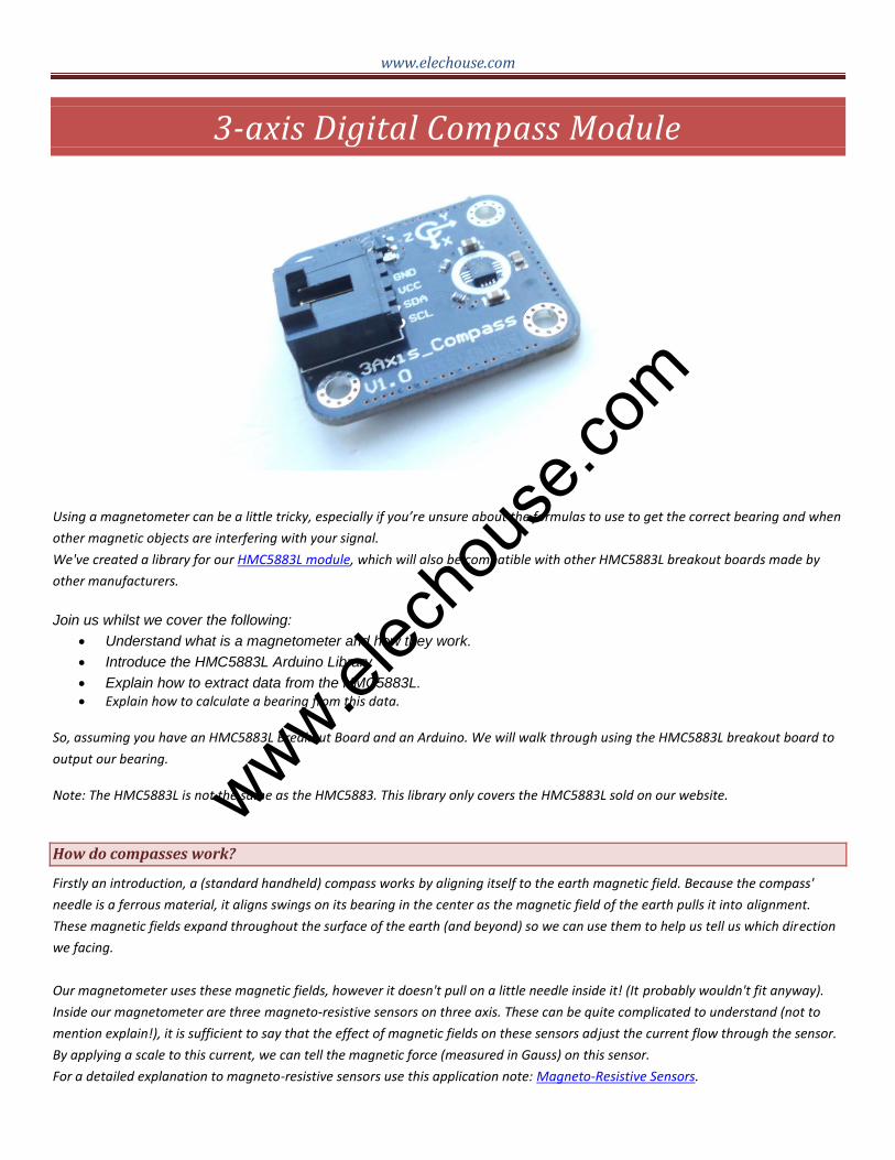
www.elechouse.com 3-axis Digital Compass Module Using a magnetometer can be a little tricky, especially if you’re unsure about the formulas to use to get the correct bearing and when other magnetic objects are interfering with your signal. We've created a library for our HMC5883L module, which will also be compatible with other HMC5883L breakout boards made by other manufacturers. Join us whilst we cover the following: Understand what is a magnetometer and how they work. Introduce the HMC5883L Arduino Library Explain how to extract data from the HMC5883L. Explain how to calculate a bearing from this data. So, assuming you have an HMC5883L Breakout Board and an Arduino. We will walk through using the HMC5883L breakout board to output our bearing. Note: The HMC5883L is not the same as the HMC5883. This library only covers the HMC5883L sold on our website. How do compasses work? Firstly an introduction, a (standard handheld) compass works by aligning itself to the earth magnetic field. Because the compass' needle is a ferrous material, it aligns swings on its bearing in the center as the magnetic field of the earth pulls it into alignment. These magnetic fields expand throughout the surface of the earth (and beyond) so we can use them to help us tell us which direction we facing. Our magnetometer uses these magnetic fields, however it doesn't pull on a little needle inside it! (It probably wouldn't fit anyway). Inside our magnetometer are three magneto-resistive sensors on three axis. These can be quite complicated to understand (not to mention explain!), it is sufficient to say that the effect of magnetic fields on these sensors adjust the current flow through the sensor. By applying a scale to this current, we can tell the magnetic force (measured in Gauss) on this sensor. For a detailed explanation to magneto-resistive sensors use this application note: Magneto-Resistive Sensors. www.elechouse.com
Transcript of 3 axis Digital Compass Module - Elechouse
www.elechouse.com
3-axis Digital Compass Module
Using a magnetometer can be a little tricky, especially if you’re unsure about the formulas to use to get the correct bearing and when
other magnetic objects are interfering with your signal.
We've created a library for our HMC5883L module, which will also be compatible with other HMC5883L breakout boards made by
other manufacturers.
Join us whilst we cover the following:
Understand what is a magnetometer and how they work.
Introduce the HMC5883L Arduino Library
Explain how to extract data from the HMC5883L.
Explain how to calculate a bearing from this data.
So, assuming you have an HMC5883L Breakout Board and an Arduino. We will walk through using the HMC5883L breakout board to
output our bearing.
Note: The HMC5883L is not the same as the HMC5883. This library only covers the HMC5883L sold on our website.
How do compasses work?
Firstly an introduction, a (standard handheld) compass works by aligning itself to the earth magnetic field. Because the compass'
needle is a ferrous material, it aligns swings on its bearing in the center as the magnetic field of the earth pulls it into alignment.
These magnetic fields expand throughout the surface of the earth (and beyond) so we can use them to help us tell us which direction
we facing.
Our magnetometer uses these magnetic fields, however it doesn't pull on a little needle inside it! (It probably wouldn't fit anyway).
Inside our magnetometer are three magneto-resistive sensors on three axis. These can be quite complicated to understand (not to
mention explain!), it is sufficient to say that the effect of magnetic fields on these sensors adjust the current flow through the sensor.
By applying a scale to this current, we can tell the magnetic force (measured in Gauss) on this sensor.
For a detailed explanation to magneto-resistive sensors use this application note: Magneto-Resistive Sensors.
www.elec
hous
e.com
www.elechouse.com
By combining information about two or more of these axis we can start to use the difference in the magnetic fields in the sensors to
infer our bearing to magnetic north.
How do we use one?
Okay, so now we know how to use one, the first step is to get some data out of our compass. The HMC5883L is a device which
communicates over I2C, a really easy communication protocol to use, and our favorite way to interface with our breakout boards
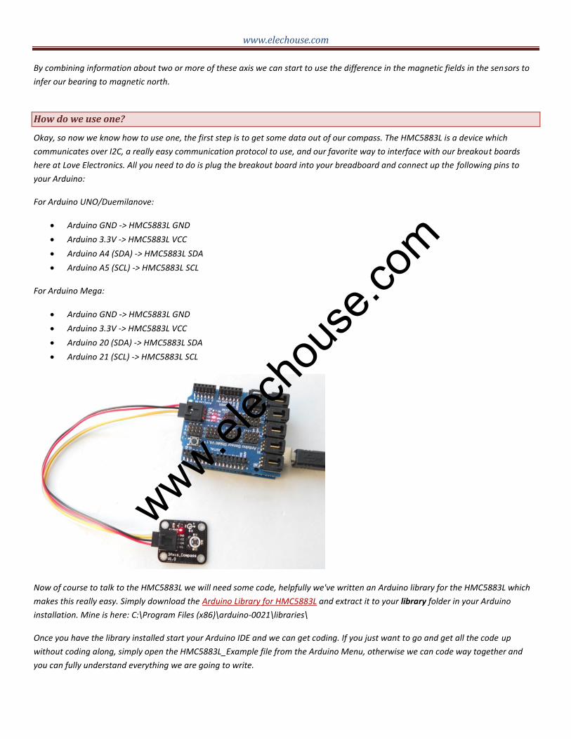
here at Love Electronics. All you need to do is plug the breakout board into your breadboard and connect up the following pins to
your Arduino:
For Arduino UNO/Duemilanove:
Arduino GND -> HMC5883L GND
Arduino 3.3V -> HMC5883L VCC
Arduino A4 (SDA) -> HMC5883L SDA
Arduino A5 (SCL) -> HMC5883L SCL
For Arduino Mega:
Arduino GND -> HMC5883L GND
Arduino 3.3V -> HMC5883L VCC
Arduino 20 (SDA) -> HMC5883L SDA
Arduino 21 (SCL) -> HMC5883L SCL
Now of course to talk to the HMC5883L we will need some code, helpfully we've written an Arduino library for the HMC5883L which
makes this really easy. Simply download the Arduino Library for HMC5883L and extract it to your library folder in your Arduino
installation. Mine is here: C:\Program Files (x86)\arduino-0021\libraries\
Once you have the library installed start your Arduino IDE and we can get coding. If you just want to go and get all the code up
without coding along, simply open the HMC5883L_Example file from the Arduino Menu, otherwise we can code way together and
you can fully understand everything we are going to write.
www.elec
hous
e.com
www.elechouse.com
Using the HMC5883L Arduino Library
What we want to accomplish is an Arduino sketch that will tell us the which direction we are pointing in degrees, so it should read 0°
for when we are point at magnetic north, and 180° when we are pointed south.
For a quick reality check, the bearing you get from your compass will be a little off, the compass senses magnetic fields, so any
ferreous material anywhere near your compass can affect your output considerably. Also any kind of radio waves (I'm looking at you
mobile phone!) and don't even let it see any stereo speakers!!
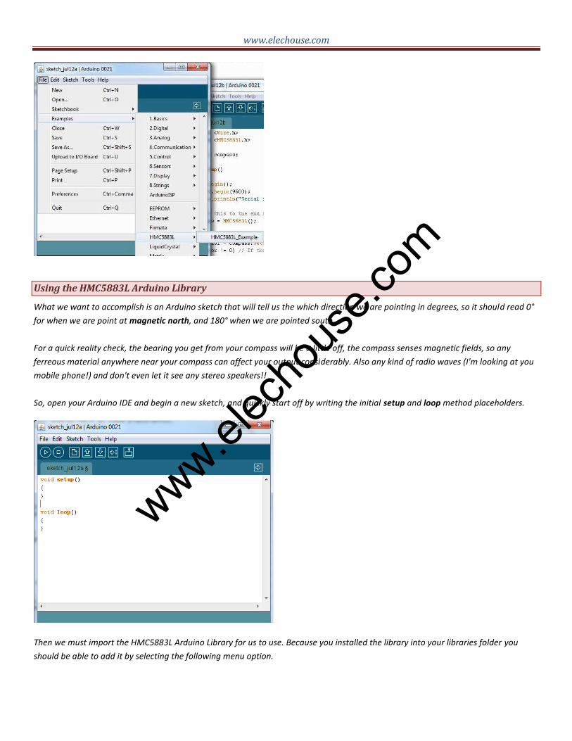
So, open your Arduino IDE and begin a new sketch, and quickly start off by writing the initial setup and loop method placeholders.
Then we must import the HMC5883L Arduino Library for us to use. Because you installed the library into your libraries folder you
should be able to add it by selecting the following menu option.
www.elec
hous
e.com

www.elechouse.com
The HMC5883L communicates over I2C, so we must also import the Wire library (do this the same way) and add the following code to
the setup() method to start the Wire library when we begin our Sketch:
Wire.begin();
We will now able to use devices on the I2C bus. We also want to communicate with our computer to report our findings,
so initialize the serial port by adding the following two lines into setup():
Serial.begin(9600);
Serial.println("Serial started.");
So, if you run this sketch we should get "Serial started." reported via the serial window. Great!
Now we need to declare an instance of the HMC5883L we can use throughout our sketch. So let’s add an HMC5883L as
a global variable by adding outside the setup() and loop() methods, and initialize it inside the setup() method.
// Add this outside the methods as a global variable. HMC5883L compass;
// Add this to the end of setup() to create an instance of HMC5883L.
compass = HMC5883L();
Once we have an instance of the compass we need to set it up, the compass needs to know what kind of gain (response
scale) to work out, and how to output its measurements. We can configure the compass by adding the following lines after
creating the compass in setup():
Serial.println("Setting scale to +/- 1.3 Ga");
int error = compass.SetScale(1.3); // Set the scale of the compass.
if(error != 0) // If there is an error, print it out.
Serial.println(compass.GetErrorText(error));
Serial.println("Setting measurement mode to continuous.");
error = compass.SetMeasurementMode(Measurement_Continuous); // Set the measurement mode to Continuous
if(error != 0) // If there is an error, print it out.
Serial.println(compass.GetErrorText(error));
www.elec
hous
e.com

www.elechouse.com
This will set the gain of the device to 1.3 Gauss (Ga), this means the device is able to report magnetic fields up to -/+ 1.3
Gauss. The lower you can make this number the more precice the compass will be, however if you have other objects
interferring with the compass you may need to raise it to avoid overloading the sensor. Bear in mind that the compass can
only accept certain gains, so check the datasheet to see what is available. If you choose an invalid gain the application
will let you know by means of the error variable the Set method returns.
Your HMC5883L should now be configured and taking measurements, all the remains is to ask the sensor the data! To
make sure we are on the same page, here is my current sketch:
So the HMC5883L Arduino Library can provide two different values for you to use. You can call either of the following:
// Retrive the raw values from the compass (not scaled). MagnetometerRaw raw = compass.ReadRawAxis();
// Retrive the scaled values from the compass (scaled to the configured scale).
MagnetometerScaled scaled = compass.ReadScaledAxis();
ReadRawAxis returns the values retrived straight from the magnetometer, if you are not interested in the actual magnetic strength
of the field you can use this to return a MagnetometerRaw structure, which has three fields for you to access the values on each axis:
www.elec
hous
e.com

www.elechouse.com
MagnetometerRaw raw = compass.ReadRawAxis();
int xAxis = raw.XAxis;
int yAxis = raw.YAxis;
int zAxis = raw.ZAxis;
The ReadScaledAxis provides the same data, in the same structure (named MagnetometerScaled), however these values are scaled
to the gain we set the device to operate (-/+ 1.3 Ga) when we called compass.SetScale(float gauss);. You can use this data when you
want to know the actual magnetic value each sensor is seeing.
Calculate your bearing
Now we know how to use the arduino library to communicate over I2C to the HMC5883L triple axis magnetometer chip we
can put a little bit of math together to calculate the bearing.
What we are going to do is add the following code to the loop() method that is going to retrive the values from the device
and do the actual bearing calculation:
void loop()
{
// Retrive the raw values from the compass (not scaled).
MagnetometerRaw raw = compass.ReadRawAxis();
// Retrived the scaled values from the compass (scaled to the configured scale).
MagnetometerScaled scaled = compass.ReadScaledAxis();
// Calculate heading when the magnetometer is level, then correct for signs of axis.
float heading = atan2(raw.YAxis, raw.XAxis);
// Correct for when signs are reversed.
if(heading < 0)
heading += 2*PI;
// Convert radians to degrees for readability.
float headingDegrees = heading * 180/M_PI;
// Output the data via the serial port.
Output(raw, scaled, heading, headingDegrees);
}
We also need to add the Output method we refer to at the end of this method:
// Output the data down the serial port.
void Output(MagnetometerRaw raw, MagnetometerScaled scaled, float heading, float headingDegrees)
{
Serial.print("Raw:\t");
Serial.print(raw.XAxis);
Serial.print(" ");
Serial.print(raw.YAxis);
www.elec
hous
e.com

www.elechouse.com
Serial.print(" ");
Serial.print(raw.ZAxis);
Serial.print(" \tScaled:\t");
Serial.print(scaled.XAxis);
Serial.print(" ");
Serial.print(scaled.YAxis);
Serial.print(" ");
Serial.print(scaled.ZAxis);
Serial.print(" \tHeading:\t");
Serial.print(heading);
Serial.print(" Radians \t");
Serial.print(headingDegrees);
Serial.println(" Degrees \t");
}
You can now go ahead and run the sketch. Assuming you have got all the code in and connected your compass properly
you should now be getting the following being reported from your serial port!
You should be able to rotate your device and see the bearing rotate from 0 to 360 degrees! Try to keep the compass
away from anything magnetic to avoid interference, but try holding something like your mobile phone next to the compass
to see how bad the effect can be on the results.
For Extra Marks
www.elec
hous
e.com
www.elechouse.com
Now you have the compass heading, you need to know that the magnetic field is not perfect around the earth, there are
changes in the ground, and the core of the earth that affect the readings, and also this even changes over time! This is
called magnetic delincation, and it can totally destroy what would otherwise be a good compass reading. For our
American users, the effect can be quite pronounced. Here is a map of this phenomenon, showing how it changes over
time: Wikipedia
Luckly we can account for this effect in our equations quite easily, at least we can if we are not flying around the world!
(Sorry Boeing...)
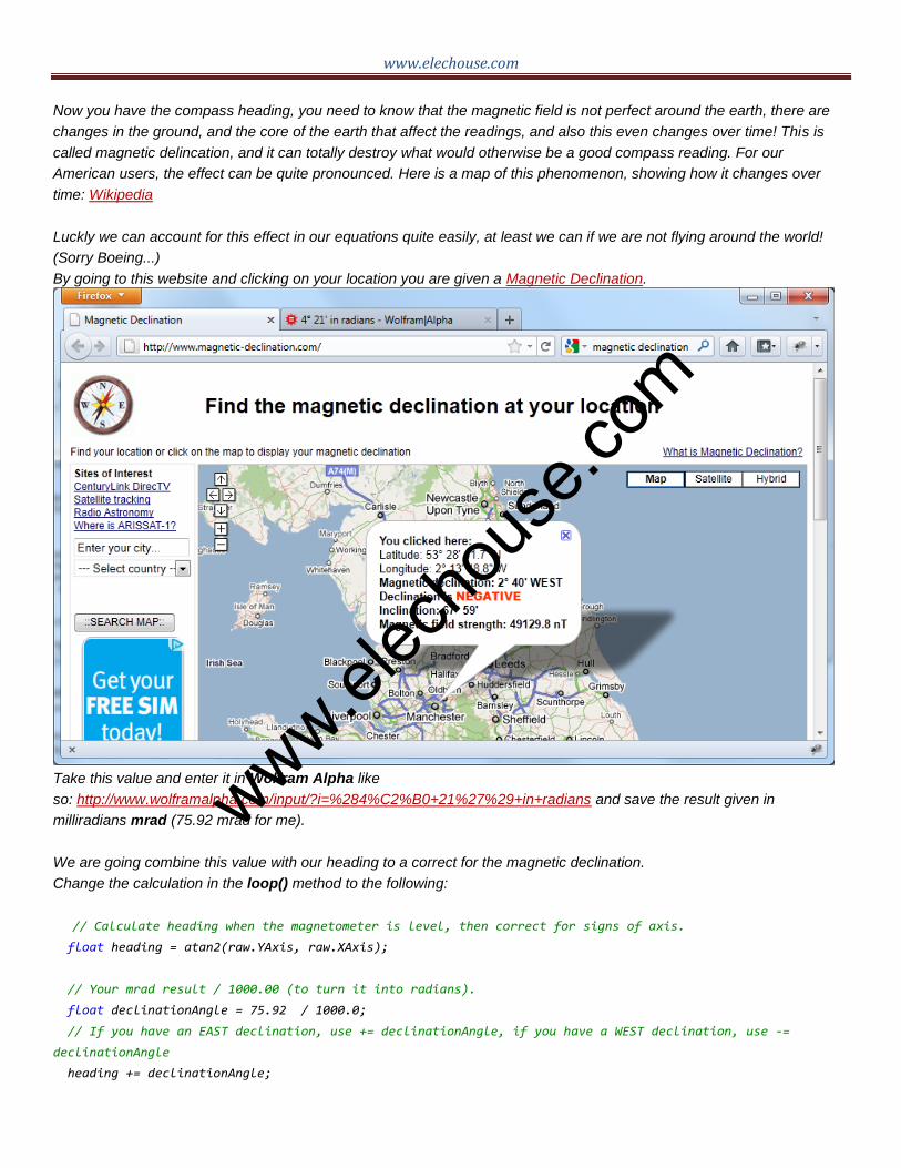
By going to this website and clicking on your location you are given a Magnetic Declination.
Take this value and enter it in Wolfram Alpha like
so: http://www.wolframalpha.com/input/?i=%284%C2%B0+21%27%29+in+radians and save the result given in
milliradians mrad (75.92 mrad for me).
We are going combine this value with our heading to a correct for the magnetic declination.
Change the calculation in the loop() method to the following:
// Calculate heading when the magnetometer is level, then correct for signs of axis. float heading = atan2(raw.YAxis, raw.XAxis);
// Your mrad result / 1000.00 (to turn it into radians).
float declinationAngle = 75.92 / 1000.0;
// If you have an EAST declination, use += declinationAngle, if you have a WEST declination, use -=
declinationAngle
heading += declinationAngle;
www.elec
hous
e.com

www.elechouse.com
// Correct for when signs are reversed.
if(heading < 0)
heading += 2*PI;
// Check for wrap due to addition of declination.
if(heading > 2*PI)
heading -= 2*PI;
// Convert radians to degrees for readability.
float headingDegrees = heading * 180/M_PI;
Congratulations! You have successfully got a bearing from your HMC5883L breakout board and corrected for the problem with
declination.
Disclaimer and Contact
The document refers to information from loveelectronic.co.uk. The information in this document may change without notice. Please visit www.elechouse.com for updating. Revision History
Rev. Date Author Description A Nov. 8th, 2011 Wilson Shen Initial version B Dec.11th,2011 Wilson Shen Add the connect information for Arduino Mega
www.elec
hous
e.com
![3-axis Electronic Compass - AKM · [AK09915] 015006484-E-02 2016/7 - 1 - AK0991 1. General Description AK09915 is 3-axis electronic compass IC with high sensitive Hall sensor technology.](https://static.fdocuments.net/doc/165x107/5adec2667f8b9af05b8b8989/3-axis-electronic-compass-akm-ak09915-015006484-e-02-20167-1-ak0991-1-general.jpg)


![AK8975/AK8975C - AKM - Asahi Kasei Microdevices - …AK8975/C] AK8975/AK8975C 3-axis Electronic Compass 1. Features A 3-axis electronic compass IC with high sensitive Hall sensor technology.](https://static.fdocuments.net/doc/165x107/5adf8edd7f8b9a8f298d1644/ak8975ak8975c-akm-asahi-kasei-microdevices-ak8975c-ak8975ak8975c-3-axis.jpg)