2x, 3x AND 5x E LECTRONIC CROSSOVER...TABLE OF CONTENTS Punch 2x, 3x and 5x Packing List 1...
28
O WNER ’ S M ANUAL 2x, 3 x AND 5x E LECTRONIC C ROSSOVER ® ®
Transcript of 2x, 3x AND 5x E LECTRONIC CROSSOVER...TABLE OF CONTENTS Punch 2x, 3x and 5x Packing List 1...
O W N E R ’ S M A N U A L
2x, 3 x A N D 5 xE L E C T R O N I C C R O S S O V E R
® ®

Dear Customer,
Congratulations on your purchase of the world's finest brand of car audio amplifiers.At Rockford Fosgate we are fanatics about musical reproduction at its best, and we arepleased you chose our product. Through years of engineering expertise, hand craftsman-ship and critical testing procedures, we have created a wide range of products thatreproduce music with all the clarity and richness you deserve.
For maximum performance we recommend you have your new Rockford Fosgateproduct installed by an Authorized Rockford Fosgate Dealer, as we provide specializedtraining through Rockford Technical Training Institute (RTTI). Please read yourwarranty and retain your receipt and original carton for possible future use.
Great product and competent installations are only a piece of the puzzle when it comesto your system. Make sure that your installer is using 100% authentic installationaccessories from Connecting Punch in your installation. Connecting Punch haseverything from RCA cables and speaker wire to Power line and battery connectors.Insist on it! After all, your new system deserves nothing but the best.
To add the finishing touch to your new Rockford Fosgate image order your Rockfordwearables, which include everything from T-shirts and jackets to hats and sunglasses.
To get a free brochure on Rockford Fosgate products and Rockford accessories, in theU.S. call 602-967-3565 or FAX 602-967-8132. For all other countries, call +001-602-967-3565 or FAX +001-602-967-8132.
If, after reading your manual, you still have questions regarding this product,we recommend that you see your Rockford Fosgate dealer. If you need furtherassistance, you can call us direct at 1-800-795-2385. Be sure to have your serialnumber, model number and date of purchase available when you call.
PRACTICE SAFE SOUND™CONTINUOUS EXPOSURE TO SOUND PRESSURE LEVELS OVER
100dB MAY CAUSE PERMANENT HEARING LOSS. HIGH
POWERED AUTOSOUND SYSTEMS MAY PRODUCE SOUND
PRESSURE LEVELS WELL OVER 130dB. USE COMMON SENSE
AND PRACTICE SAFE SOUND.
The serial number can be found on the outside of the box. Please record it inthe space provided below as your permanent record. This will serve asverification of your factory warranty and may become useful in recovering youramplifier if it is ever stolen.
Serial Number: ________________________________
Model Number: ________________________________
T A B L E O F C O N T E N T S
Punch 2x, 3x and 5x Packing List ................................................. 1
Introduction ................................................................................. 1
Operating Features ................................................................. 1
Design Features ............................................................................ 2
1. Gold Plated RCA Jacks ....................................................... 3
2. Power Terminals ................................................................ 3
3. LED Power Indicator .......................................................... 3
4. XCards ............................................................................... 3
5. Input Mode Switch (3x and 5x only) ................................... 3
6. Phase Switch (3x and 5x only) ............................................ 4
7. Mounting Holes ................................................................. 4
8. Fusing ................................................................................ 4
Installation Considerations ........................................................... 5
Mounting and Wiring the Active Crossover .................................. 6
B+ .......................................................................................... 6
GND ...................................................................................... 6
REM ....................................................................................... 6
Input/Output Levels & Connections ........................................ 6
Selecting the XCards .................................................................... 7
Using The Dual Filter (3x and 5x only) ......................................... 8
Installing the XCards .................................................................... 8
Filter Effects .................................................................................. 9
Wiring Diagrams ........................................................................ 10
Appendix A - Building A Custom XCard ..................................... 18
Butterworth Resistor Chart .......................................................... 19
Specifications ............................................................................. 20Warranty .................................................................................... 21
PUNCH 2X/3X/5X PACKING LIST
Punch Electronic CrossoverOwner's Manual
This manual provides information on the features, installation andoperation of the Punch 2x, 3x and 5x Electronic Crossover. Wesuggest you save this manual for future reference.
We strongly recommend you have your Authorized Rockford FosgateDealer install your new active crossover. If you do choose to install theunit yourself, please be sure to read the entire manual before begin-ning your installation.
OPERATING FEATURESThe Punch 2x, 3x and 5x Electronic Crossovers provide for state-of-the-art flexibility and performance demanded by today’s car audioenthusiasts. Features include:
XCards – 3-Way Selectable Electronic Crossover modules thatfeature 12dB per octave filters that give precise crossover points andallow for individual selection of high-pass, low-pass or full range filteroperation.
Dual Filtered, Non-Faded Output with Phase Reversal Switch (3xand 5x only) allows you to create various pass band configurations.In addition, the phase reversal switch enables you to easily correct forphase problems that may be inherent in some system designs.
2 Channel Input on the Punch 2x
2 or 4-Channel Input Mode Switch (3x and 5x only) enables you toselect two (2) or four (4) channels of input.
4 Outputs on the Punch 2x
6 Outputs on the Punch 3x for Front, Rear and a Dual-Filtered, Non-Faded Output.
10 Outputs on the Punch 5x – In addition to the outputs found on thePunch 3x, the 5x also has Front and Rear Dual-Filtered Outputs forcreating additional pass band filter combinations.
Gold Plated RCA Input and Output Jacks reduce corrosion which cancause signal deterioration over time.
– 1 –
I N T R O D U C T I O N
D E S I G N F E A T U R E S
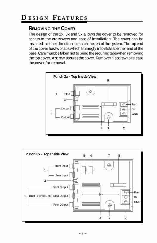
REMOVING THE COVERThe design of the 2x, 3x and 5x allows the cover to be removed foraccess to the crossovers and ease of installation. The cover can beinstalled in either direction to match the rest of the system. The top endof the cover has two tabs which fit snugly into slots at either end of thebase. Care must be taken not to bend the securing tabs when removingthe top cover. A screw secures the cover. Remove this screw to releasethe cover for removal.
Punch 3x - Top Inside View
7
Front Input
Rear Input
1
3
2
Rem
B+
GND
7
Front Output
Dual Filtered Non-Faded Output
Rear Output
4
5 6 8
1
– 2 –
Rem
B+
GND
3
Input1
1Output
Output
4 7 2
Punch 2x - Top Inside View8
– 3 –
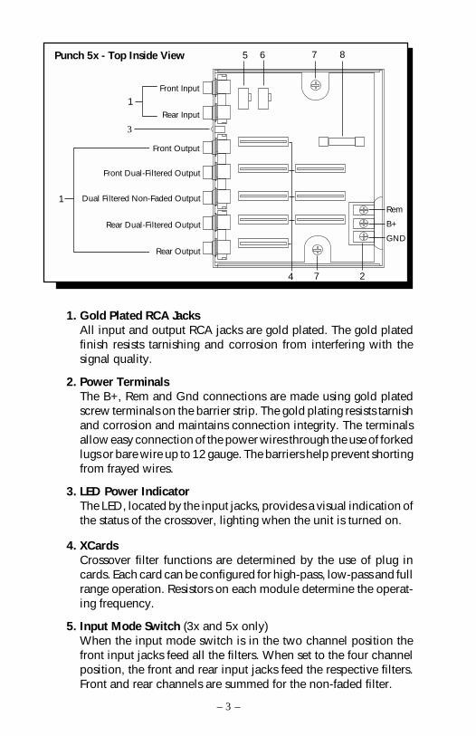
Punch 5x - Top Inside View
Rem
B+
GND
7 86
27
1Front Input
Rear Input
Front Output
Front Dual-Filtered Output
3
Dual Filtered Non-Faded Output
Rear Dual-Filtered Output
Rear Output
1
4
5
1. Gold Plated RCA JacksAll input and output RCA jacks are gold plated. The gold platedfinish resists tarnishing and corrosion from interfering with thesignal quality.
2. Power TerminalsThe B+, Rem and Gnd connections are made using gold platedscrew terminals on the barrier strip. The gold plating resists tarnishand corrosion and maintains connection integrity. The terminalsallow easy connection of the power wires through the use of forkedlugs or bare wire up to 12 gauge. The barriers help prevent shortingfrom frayed wires.
3. LED Power IndicatorThe LED, located by the input jacks, provides a visual indication ofthe status of the crossover, lighting when the unit is turned on.
4. XCardsCrossover filter functions are determined by the use of plug incards. Each card can be configured for high-pass, low-pass and fullrange operation. Resistors on each module determine the operat-ing frequency.
5. Input Mode Switch (3x and 5x only)When the input mode switch is in the two channel position thefront input jacks feed all the filters. When set to the four channelposition, the front and rear input jacks feed the respective filters.Front and rear channels are summed for the non-faded filter.
6. Phase Switch (3x and 5x only)The phase switch allows easy invertion polarity on the non-fadedoutput to optimize sound quality.
7. Mounting HolesThe crossover must be mounted on a flat surface. Two mountingholes in the bottom are used to secure the crossover.
8. FusingThe crossover has a 1/2 amp AGC fast blow power protection fuse.If it is necessary to replace the fuse, use only the same type andrating or the warranty may be voided.
– 4 –

IN S TA L L AT I O N CO N S I D E R AT I O N S
This section focuses on some of the vehicle considerations forinstalling your new Punch Electronic Crossover. Checking yourbattery and current sound system, as well as pre-planning your systemlayout and best wiring routes will save installation time. Whendeciding how to lay out your new system, be sure that each compo-nent will be easily accessible for making adjustments.
Before beginning any installation, be sure to follow these simple rules:
1. Be sure to carefully read and understand the instructions beforeattempting to install the crossover.
2. For safety, disconnect the negative lead from the battery prior tobeginning the installation.
3. For easier assembly, we suggest you run all wires prior tomounting your electronic crossover in place.
4. Route all of the RCA cables close together and away from anyhigh current wires. this will help reduce noise.
5. Use high quality connectors for a reliable installation and tominimize signal or power loss. See your Authorized RockfordFosgate Dealer for wire enhancements.
6. Think before you drill! Be careful not to cut or drill into gas tanks,fuel lines, brake or hydraulic lines, vacuum lines or electricalwiring when working on any vehicle.
7. Never run wires underneath the vehicle. Running the wiresinside the vehicle provides for best protection.
8. Avoid running wires over or through sharp edges. Use rubber orplastic grommets to protect any wires routed through metal,especially the firewall.
9. ALWAYS protect the battery and electrical system from damagewith proper fusing. Install a fuse holder and fuse on the +12Vpower wire within 18” (45.7 cm) of the battery terminal.
10. When grounding to the chassis of the vehicle, scrape all paintfrom the metal to ensure a good, clean ground connection.Grounding connections should be as short as possible and alwaysbe connected to metal that is welded to the main body, or chassis,of the vehicle. Use of a continuity meter will confirm a properground.
– 5 –
M O U N T I N G A N D W I R I N G T H E
E L E C T R O N I C C R O S S O V E R S
– 6 –
The information below describes the various considerations formounting and connecting the active crossovers. For additional infor-mation see the wiring diagrams beginning on page 10.
We recommend mounting the crossover as close to the amplifier(s) aspossible.
The B+ (Power) supplies power to the unit. Connect this terminal toa constant +12 Volt power source by way of an in-line fuse.
The GND (Power Ground) grounds the unit. Connect this terminal tothe chassis of the vehicle. When grounding the unit be sure to scrapeall paint from the metal to ensure a clean electrical connection.
The REM (Remote Turn-On) turns on the unit by way of a +12 Voltsupply source. Connect this terminal to the source unit’s “Amplifier”or “Auto Antenna” lead, either of which will go to +12 volts wheneverthe source unit is on.
If your source unit does not have either a Remote or an Auto Antennalead (or if the Auto Antenna goes down during tape operation), werecommend installing a switch to control the unit manually.
INPUT/OUTPUT LEVELS & CONNECTIONSThe Punch Electronic Crossovers are designed for preamp (input upto 2VRMS) levels. Net gain in the crossover is unity. (Output levels areequal to input levels.)
When connecting the input and output terminals be sure to use highquality shielded interconnecting RCA cables.
• Connect source unit's OUTPUT jacks to the desired crossoverINPUT jacks.
• Connect the desired crossover’s OUTPUT jacks to the Amplifier’sINPUT jacks.
SELECTING THE XCARDS
– 7 –
Punch 3x
100 Hz
100 Hz
Output
Output
100 Hz
100 Hz
100 Hz
Blank
Rear Output
Dual FilteredNon-Faded Output
Front Output
Punch 2x
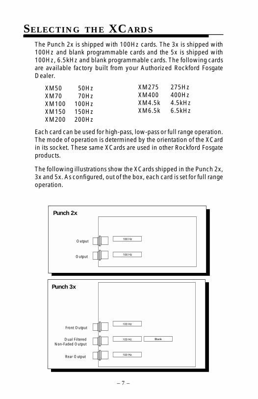
The Punch 2x is shipped with 100Hz cards. The 3x is shipped with100Hz and blank programmable cards and the 5x is shipped with100Hz, 6.5kHz and blank programmable cards. The following cardsare available factory built from your Authorized Rockford FosgateDealer.
XM50 50HzXM70 70HzXM100 100HzXM150 150HzXM200 200Hz
Each card can be used for high-pass, low-pass or full range operation.The mode of operation is determined by the orientation of the XCardin its socket. These same XCards are used in other Rockford Fosgateproducts.
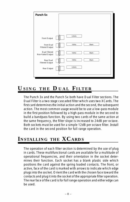
The following illustrations show the XCards shipped in the Punch 2x,3x and 5x. As configured, out of the box, each card is set for full rangeoperation.
XM275 275HzXM400 400HzXM4.5k 4.5kHzXM6.5k 6.5kHz
Punch 5x
6.5kHz
100Hz
100Hz
100Hz
6.5kHz
Blank
Blank
Blank
Front Output
Front DualFiltered Output
Dual FilteredNon-Faded Output
Rear DualFiltered Output
Rear Output
– 8 –
U S I N G T H E D U A L F I LT E R
The Punch 3x and the Punch 5x both have Dual Filter sections. TheDual Filter is a two stage cascaded filter which uses two XCards. Thefirst card determines the initial action and the second, the subsequentaction. The most common usage would be to use a low-pass modulein the first position followed by a high-pass module in the second tobuild a bandpass function. By using two cards of the same action atthe same frequency, the filter slope is increased to 24dB per octave.Both sockets must be used for a simple 12dB per octave filter. Installthe card in the second position for full range operation.
The operation of each filter section is determined by the use of plugin cards. These multifunctional cards are available for a multitude ofoperational frequencies, and their orientation in the socket deter-mines their function. Each socket has a blank plastic side whichpositions the card against the spring loaded contacts. The front, oractive, face of the card is marked with arrows to indicate which edgeplugs into the socket. Orient the card with the chosen face toward thecontacts and plug it into the socket of the appropriate filter operation.The rear face of the card is for full range operation and either edge canbe used.
INSTALLING THE XCARDS
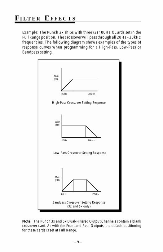
Example: The Punch 3x ships with three (3) 100Hz XCards set in theFull Range position. The crossover will pass through all 20Hz - 20kHzfrequencies. The following diagram shows examples of the types ofresponse curves when programming for a High-Pass, Low-Pass orBandpass setting.
– 9 –
High-Pass Crossover Setting Response
Low-Pass Crossover Setting Response
Bandpass Crossover Setting Response(3x and 5x only)
Note: The Punch 3x and 5x Dual-Filtered Output Channels contain a blankcrossover card. As with the Front and Rear Outputs, the default positioningfor these cards is set at Full Range.
F I L T E R E F F E C T S
Gain(dB)
20Hz 20kHz
Gain(dB)
20Hz 20kHz
Gain(dB)
20Hz 20kHz
W I R I N G D I A G R A M S
– 10 –
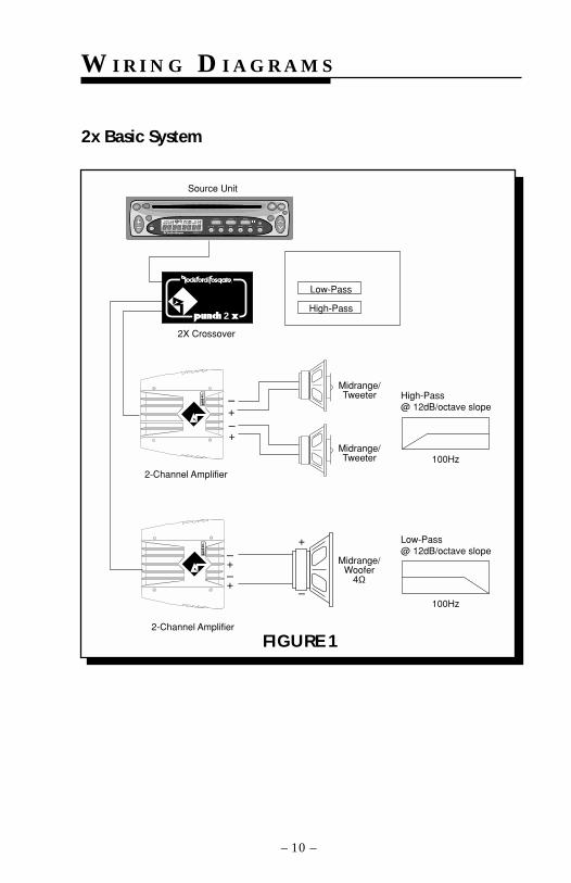
FIGURE 1
2x Basic System
Midrange/Tweeter
2-Channel Amplifier
2-Channel Amplifier
Source Unit
2X Crossover
–+–+
–
+
–+–+
Midrange/Woofer
4Ω
Low-Pass
High-Pass
Midrange/Tweeter
High-Pass@ 12dB/octave slope
100Hz
Low-Pass@ 12dB/octave slope
100Hz
®
®
2
AUD SEL
1 2 3 4 5 6
RDMRPTSCAN PAUSED.SCN DIM
AMFMCh
RPTLD RDMDISC
ST P.SCN LOUDDSPL
R
CLOCK ILLUM
PWR
AUTO
® ®
VOL TUNE
– 11 –
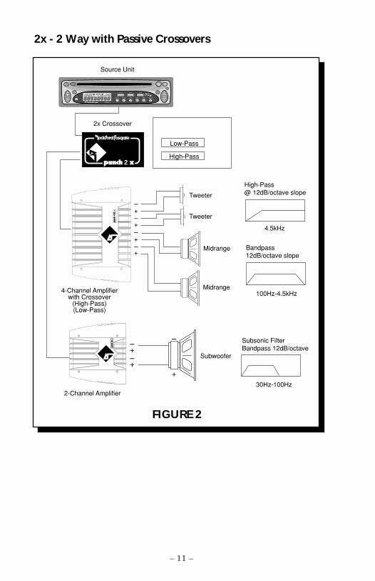
2x - 2 Way with Passive Crossovers
FIGURE 2
100Hz-4.5kHz
Tweeter
4-Channel Amplifierwith Crossover
(High-Pass)(Low-Pass)
2-Channel Amplifier
Source Unit
2x Crossover
–+–+
High-Pass@ 12dB/octave slope
Midrange
–
+
Subsonic FilterBandpass 12dB/octave
Subwoofer
–+–+–+–+
Tweeter
Midrange
4.5kHz
Low-Pass
High-Pass
Bandpass12dB/octave slope
30Hz-100Hz
®
®
2
AUD SEL
1 2 3 4 5 6
RDMRPTSCAN PAUSED.SCN DIM
AMFMCh
RPTLD RDMDISC
ST P.SCN LOUDDSPL
R
CLOCK ILLUM
PWR
AUTO
® ®
VOL TUNE
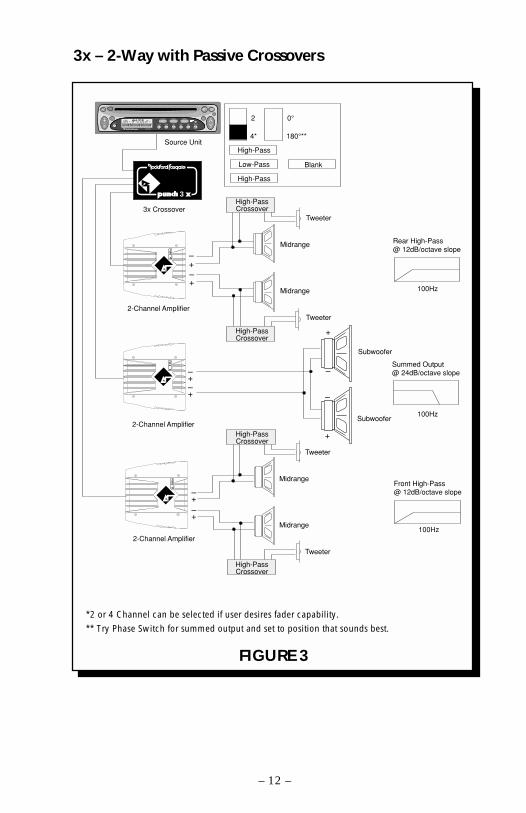
3x – 2-Way with Passive Crossovers
*2 or 4 Channel can be selected if user desires fader capability.
** Try Phase Switch for summed output and set to position that sounds best.
FIGURE 3
– 12 –
Tweeter
Tweeter
Midrange
Midrange
Subwoofer
2-Channel Amplifier
2-Channel Amplifier
2-Channel Amplifier
Source Unit
3x Crossover
–+–+
–
+
–
+
–+–+
–+–+
High-PassCrossover
Tweeter
Tweeter
Midrange
Midrange
Subwoofer
Front High-Pass@ 12dB/octave slope
Rear High-Pass@ 12dB/octave slope
Summed Output@ 24dB/octave slope
High-PassCrossover
High-PassCrossover
High-PassCrossover
0°
180°**
2
4*
High-Pass
Low-Pass
High-Pass
Blank
100Hz
100Hz
100Hz
3®
®
AUD SEL
1 2 3 4 5 6
RDMRPTSCAN PAUSED.SCN DIM
AMFMCh
RPTLD RDMDISC
ST P.SCN LOUDDSPL
R
CLOCK ILLUM
PWR
AUTO
® ®
VOL TUNE
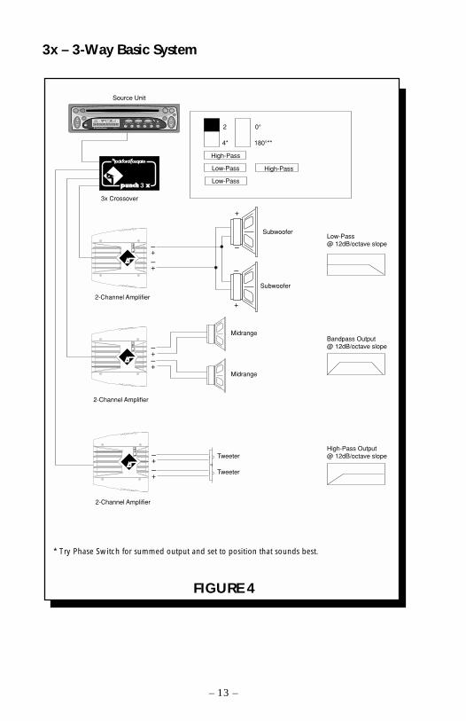
FIGURE 4
* Try Phase Switch for summed output and set to position that sounds best.
– 13 –
3x – 3-Way Basic System
Subwoofer
2-Channel Amplifier
2-Channel Amplifier
2-Channel Amplifier
Source Unit
3x Crossover
–+–+
–
+
–
+
–+–+
–+–+
Tweeter
Tweeter
Midrange
Midrange
Subwoofer
High-Pass
Low-Pass
Low-Pass
High-Pass
Low-Pass@ 12dB/octave slope
Bandpass Output@ 12dB/octave slope
High-Pass Output@ 12dB/octave slope
0°
180°**
2
4*
3®
®
AUD SEL
1 2 3 4 5 6
RDMRPTSCAN PAUSED.SCN DIM
AMFMCh
RPTLD RDMDISC
ST P.SCN LOUDDSPL
R
CLOCK ILLUM
PWR
AUTO
® ®
VOL TUNE
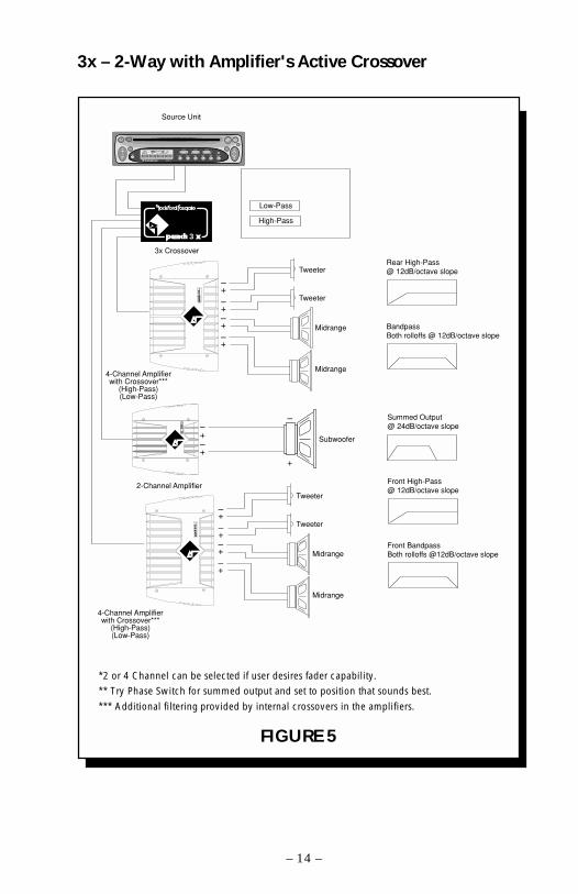
3x – 2-Way with Amplifier's Active Crossover
*2 or 4 Channel can be selected if user desires fader capability.
** Try Phase Switch for summed output and set to position that sounds best.
*** Additional filtering provided by internal crossovers in the amplifiers.
FIGURE 5
– 14 –
Tweeter
Subwoofer
4-Channel Amplifierwith Crossover***
(High-Pass)(Low-Pass)
2-Channel Amplifier
Source Unit
3x Crossover
–+–+
–
+
–+–+
Low-Pass
High-Pass
Summed Output@ 24dB/octave slope
Tweeter
Rear High-Pass@ 12dB/octave slope
BandpassBoth rolloffs @ 12dB/octave slope
–+–+
Midrange
Midrange
3®
®
Tweeter
4-Channel Amplifierwith Crossover***
(High-Pass)(Low-Pass)
–+–+
Tweeter
–+–+
Midrange
Midrange
Front High-Pass@ 12dB/octave slope
Front BandpassBoth rolloffs @12dB/octave slope
AUD SEL
1 2 3 4 5 6
RDMRPTSCAN PAUSED.SCN DIM
AMFMCh
RPTLD RDMDISC
ST P.SCN LOUDDSPL
R
CLOCK ILLUM
PWR
AUTO
® ®
VOL TUNE
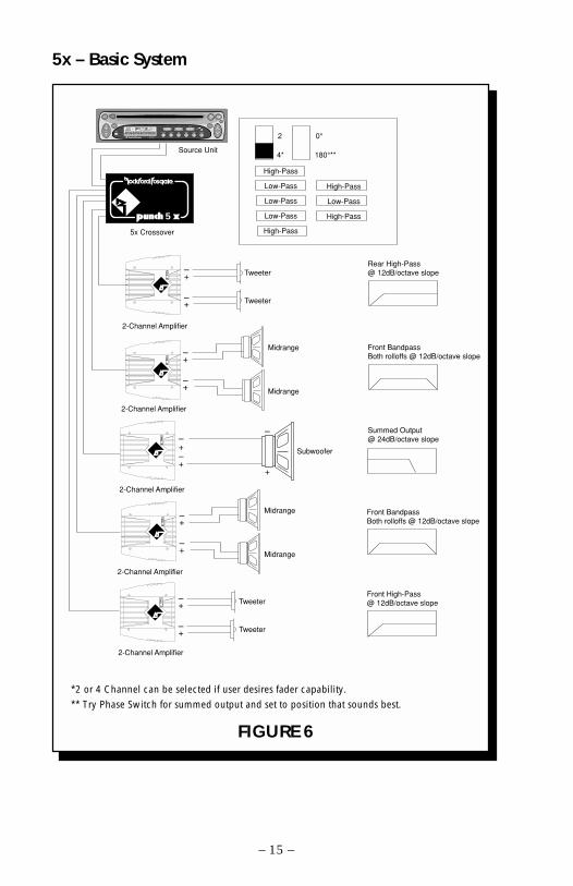
5x – Basic System
*2 or 4 Channel can be selected if user desires fader capability.
** Try Phase Switch for summed output and set to position that sounds best.
FIGURE 6
– 15 –
2-Channel Amplifier
–+
–+
Midrange
Midrange
Tweeter
2-Channel Amplifier
Source Unit
5x Crossover
–+
–+
Summed Output@ 24dB/octave slope
Tweeter
Front High-Pass@ 12dB/octave slope
Rear High-Pass@ 12dB/octave slope
Front BandpassBoth rolloffs @ 12dB/octave slope
2-Channel Amplifier
–+
–+
Midrange
Midrange
Front BandpassBoth rolloffs @ 12dB/octave slope
Tweeter
2-Channel Amplifier
–+
–+ Tweeter
Subwoofer
2-Channel Amplifier
–
+
–+–+
5®
®
High-Pass
Low-Pass
Low-Pass
Low-Pass
High-Pass
High-Pass
Low-Pass
High-Pass
0°
180°**
2
4*
AUD SEL
1 2 3 4 5 6
RDMRPTSCAN PAUSED.SCN DIM
AMFMCh
RPTLD RDMDISC
ST P.SCN LOUDDSPL
R
CLOCK ILLUM
PWR
AUTO
® ®
VOL TUNE
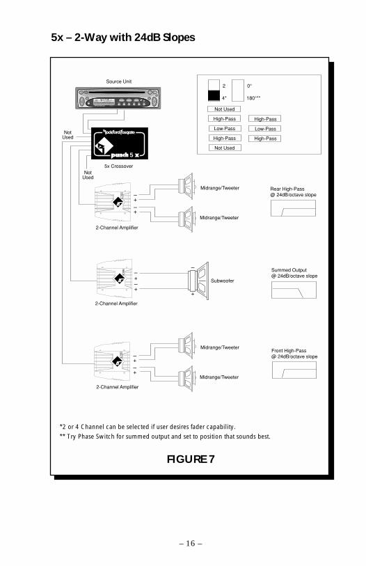
5x – 2-Way with 24dB Slopes
FIGURE 7
*2 or 4 Channel can be selected if user desires fader capability.
** Try Phase Switch for summed output and set to position that sounds best.
– 16 –
Midrange/Tweeter
Subwoofer
2-Channel Amplifier
2-Channel Amplifier
2-Channel Amplifier
Source Unit
5x Crossover
–+–+
–
+
–+–+
–+–+
Summed Output@ 24dB/octave slope
Midrange/Tweeter
Midrange/Tweeter
Midrange/Tweeter
Front High-Pass@ 24dB/octave slope
Rear High-Pass@ 24dB/octave slope
NotUsed
NotUsed
Not Used
High-Pass
Low-Pass
High-Pass
Not Used
High-Pass
Low-Pass
High-Pass
0°
180°**
2
4*
5®
®
AUD SEL
1 2 3 4 5 6
RDMRPTSCAN PAUSED.SCN DIM
AMFMCh
RPTLD RDMDISC
ST P.SCN LOUDDSPL
R
CLOCK ILLUM
PWR
AUTO
® ®
VOL TUNE
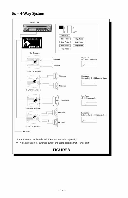
5x – 4-Way System
FIGURE 8
*2 or 4 Channel can be selected if user desires fader capability.
** Try Phase Switch for summed output and set to position that sounds best.
– 17 –
Tweeter
2-Channel Amplifier
Source Unit
5x Crossover
–+
–+ Tweeter
Low-Pass@ 24dB/octave slope
High-Pass@ 12dB/octave slope
BandpassBoth rolloffs @ 12dB/octave slope
Not Used
Low-Pass
Low-Pass
Low-Pass
High-Pass
High-Pass
Low-Pass
High-Pass
2-Channel Amplifier
–+
–+
Midrange
Midrange
BandpassBoth rolloffs @ 12dB/octave slope
Subwoofer
Not Used**
–
+
2-Channel Amplifier
–+
–+
Mid Bass
Mid Bass
2-Channel Amplifier
–+–+
0°
180°**
2
4
5®
®
AUD SEL
1 2 3 4 5 6
RDMRPTSCAN PAUSED.SCN DIM
AMFMCh
RPTLD RDMDISC
ST P.SCN LOUDDSPL
R
CLOCK ILLUM
PWR
AUTO
® ®
VOL TUNE
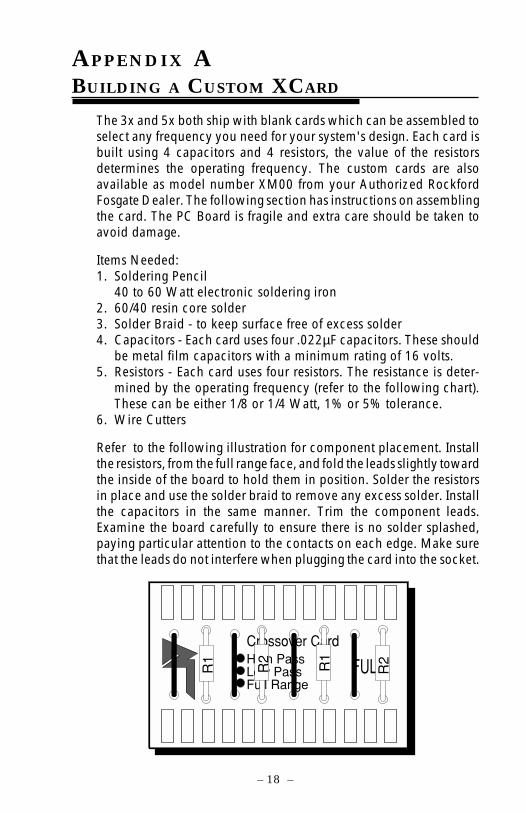
APPENDIX ABUILDING A CUSTOM XCARD
– 18 –
The 3x and 5x both ship with blank cards which can be assembled toselect any frequency you need for your system's design. Each card isbuilt using 4 capacitors and 4 resistors, the value of the resistorsdetermines the operating frequency. The custom cards are alsoavailable as model number XM00 from your Authorized RockfordFosgate Dealer. The following section has instructions on assemblingthe card. The PC Board is fragile and extra care should be taken toavoid damage.
Items Needed:1. Soldering Pencil
40 to 60 Watt electronic soldering iron2. 60/40 resin core solder3. Solder Braid - to keep surface free of excess solder4. Capacitors - Each card uses four .022µF capacitors. These should
be metal film capacitors with a minimum rating of 16 volts.5. Resistors - Each card uses four resistors. The resistance is deter-
mined by the operating frequency (refer to the following chart).These can be either 1/8 or 1/4 Watt, 1% or 5% tolerance.
6. Wire Cutters
Refer to the following illustration for component placement. Installthe resistors, from the full range face, and fold the leads slightly towardthe inside of the board to hold them in position. Solder the resistorsin place and use the solder braid to remove any excess solder. Installthe capacitors in the same manner. Trim the component leads.Examine the board carefully to ensure there is no solder splashed,paying particular attention to the contacts on each edge. Make surethat the leads do not interfere when plugging the card into the socket.
Crossover CardHigh PassLow PassFull Range
FULL R2
R1
R2
R1
Freq. R118.5Hz 390k Ohm26Hz 270k Ohm33Hz 220k Ohm40Hz 180k Ohm48Hz 150k Ohm60Hz 120k Ohm72Hz 100k Ohm88Hz 82k Ohm
106Hz 68k Ohm130Hz 56k Ohm154Hz 47k Ohm185Hz 39k Ohm220Hz 33k Ohm270Hz 27k Ohm330Hz 22k Ohm400Hz 18k Ohm480Hz 15k Ohm600Hz 12k Ohm720Hz 10k Ohm880Hz 8.2k Ohm
1.06kHz 6.8k Ohm1.3kHz 5.6k Ohm
1.54kHz 4.7k Ohm1.85kHz 3.9k Ohm2.2kHz 3.3k Ohm2.7kHz 2.7k Ohm3.3kHz 2.2k Ohm4.0kHz 1.8k Ohm4.8kHz 1.5k Ohm6.0kHz 1.2k Ohm7.2kHz 1k Ohm8.8kHz 820 Ohm
10.6kHz 680 Ohm13.0kHz 560 Ohm15.4kHz 470 Ohm
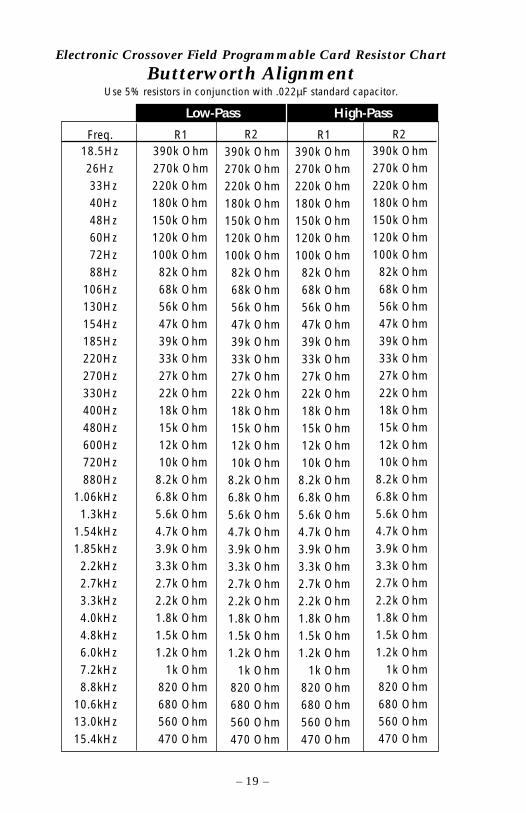
Electronic Crossover Field Programmable Card Resistor Chart
Butterworth AlignmentUse 5% resistors in conjunction with .022µF standard capacitor.
390k Ohm270k Ohm220k Ohm180k Ohm150k Ohm120k Ohm100k Ohm
82k Ohm68k Ohm56k Ohm47k Ohm39k Ohm33k Ohm27k Ohm22k Ohm18k Ohm15k Ohm12k Ohm10k Ohm
8.2k Ohm6.8k Ohm5.6k Ohm4.7k Ohm3.9k Ohm3.3k Ohm2.7k Ohm2.2k Ohm1.8k Ohm1.5k Ohm1.2k Ohm
1k Ohm820 Ohm680 Ohm560 Ohm470 Ohm
R2 R1 R2
Low-Pass High-Pass
390k Ohm270k Ohm220k Ohm180k Ohm150k Ohm120k Ohm100k Ohm
82k Ohm68k Ohm56k Ohm47k Ohm39k Ohm33k Ohm27k Ohm22k Ohm18k Ohm15k Ohm12k Ohm10k Ohm
8.2k Ohm6.8k Ohm5.6k Ohm4.7k Ohm3.9k Ohm3.3k Ohm2.7k Ohm2.2k Ohm1.8k Ohm1.5k Ohm1.2k Ohm
1k Ohm820 Ohm680 Ohm560 Ohm470 Ohm
390k Ohm270k Ohm220k Ohm180k Ohm150k Ohm120k Ohm100k Ohm82k Ohm68k Ohm56k Ohm47k Ohm39k Ohm33k Ohm27k Ohm22k Ohm18k Ohm15k Ohm12k Ohm10k Ohm
8.2k Ohm6.8k Ohm5.6k Ohm4.7k Ohm3.9k Ohm3.3k Ohm2.7k Ohm2.2k Ohm1.8k Ohm1.5k Ohm1.2k Ohm
1k Ohm820 Ohm680 Ohm560 Ohm470 Ohm
– 19 –
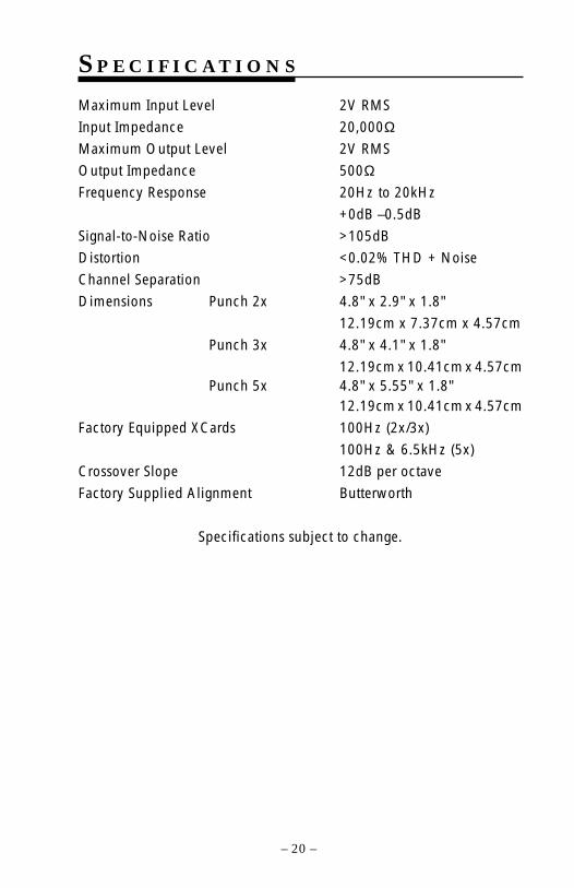
S P E C I F I C A T I O N S
Maximum Input Level 2V RMS
Input Impedance 20,000ΩMaximum Output Level 2V RMS
Output Impedance 500ΩFrequency Response 20Hz to 20kHz
+0dB –0.5dB
Signal-to-Noise Ratio >105dB
Distortion <0.02% THD + Noise
Channel Separation >75dB
Dimensions Punch 2x 4.8" x 2.9" x 1.8"
12.19cm x 7.37cm x 4.57cm
Punch 3x 4.8" x 4.1" x 1.8"
12.19cm x 10.41cm x 4.57cmPunch 5x 4.8" x 5.55" x 1.8"
12.19cm x 10.41cm x 4.57cm
Factory Equipped XCards 100Hz (2x/3x)
100Hz & 6.5kHz (5x)
Crossover Slope 12dB per octave
Factory Supplied Alignment Butterworth
Specifications subject to change.
– 20 –
WARRANTY INFORMATION
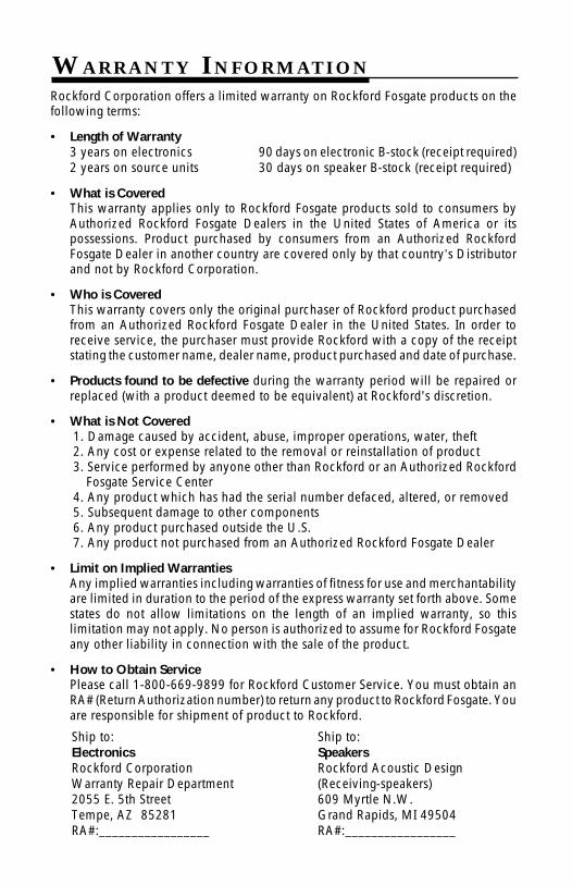
Ship to:SpeakersRockford Acoustic Design(Receiving-speakers)609 Myrtle N.W.Grand Rapids, MI 49504RA#:_________________
Ship to:ElectronicsRockford CorporationWarranty Repair Department2055 E. 5th StreetTempe, AZ 85281RA#:_________________
Rockford Corporation offers a limited warranty on Rockford Fosgate products on thefollowing terms:
• Length of Warranty3 years on electronics 90 days on electronic B-stock (receipt required)2 years on source units 30 days on speaker B-stock (receipt required)
• What is CoveredThis warranty applies only to Rockford Fosgate products sold to consumers byAuthorized Rockford Fosgate Dealers in the United States of America or itspossessions. Product purchased by consumers from an Authorized RockfordFosgate Dealer in another country are covered only by that country’s Distributorand not by Rockford Corporation.
• Who is CoveredThis warranty covers only the original purchaser of Rockford product purchasedfrom an Authorized Rockford Fosgate Dealer in the United States. In order toreceive service, the purchaser must provide Rockford with a copy of the receiptstating the customer name, dealer name, product purchased and date of purchase.
• Products found to be defective during the warranty period will be repaired orreplaced (with a product deemed to be equivalent) at Rockford's discretion.
• What is Not Covered1. Damage caused by accident, abuse, improper operations, water, theft2. Any cost or expense related to the removal or reinstallation of product3. Service performed by anyone other than Rockford or an Authorized Rockford
Fosgate Service Center4. Any product which has had the serial number defaced, altered, or removed5. Subsequent damage to other components6. Any product purchased outside the U.S.7. Any product not purchased from an Authorized Rockford Fosgate Dealer
• Limit on Implied WarrantiesAny implied warranties including warranties of fitness for use and merchantabilityare limited in duration to the period of the express warranty set forth above. Somestates do not allow limitations on the length of an implied warranty, so thislimitation may not apply. No person is authorized to assume for Rockford Fosgateany other liability in connection with the sale of the product.
• How to Obtain ServicePlease call 1-800-669-9899 for Rockford Customer Service. You must obtain anRA# (Return Authorization number) to return any product to Rockford Fosgate. Youare responsible for shipment of product to Rockford.

N O T E S

N O T E S


MAN-0677-A1/94
Rockford Corporation546 South Rockford Drive
Tempe, Arizona 85281 U.S.A.In U.S.A., (602) 967-3565
In Europe, Fax (49) 4207-801250In Japan, Fax (81) 559-79-1265