2$N$ 2/4+ O/I- A6 22$A 2$N$ 2$AC 4 -...
20
3 leveling with roller levelers Preface We are pleased the high demand for ”Leveling with Roller Levelers” has remained strong for over 20 years. With continued strong demand, we strive to raise the standard on leveling technology. Now, 80 years after ARKU was founded, we're pleased to announce publication and release of the fourth edition of ”Leveling with Roller Levelers”. This new edition is filled with color illustrations and a modern layout. We've revised ”Leveling with Roller Levelers” to meet the needs of today's readers. The topic of sheet leveling is more current than ever. Leveling improves the quality of sheet metal processing. The improved tolerances in the flatness of sheet metal parts and coils are obvious. Less obvious are the favourable distribution of residual stresses in the material, which stabilizes the material for the subsequent processes like folding, bending and roll forming. We would also like to take the opportunity to thank Prof. Dr.-Ing. Horst Bräutigam. For nearly 30 years, the author has skillfully combined science and application. Your feedback and constructive criticism is crucial for ARKU to maintain our position as your leveling experts for the future. We look forward to hearing from you! Your Albert Reiss Baden-Baden, July 2009
Transcript of 2$N$ 2/4+ O/I- A6 22$A 2$N$ 2$AC 4 -...

3
leveling with roller levelers
Preface
We are pleased the high demand for ”Leveling withRoller Levelers” has remained strong for over20 years. With continued strong demand, we striveto raise the standard on leveling technology.
Now, 80 years after ARKU was founded, we're pleased to announce publicationand release of the fourth edition of ”Leveling with Roller Levelers”.This new edition is filled with color illustrations and a modern layout. We'verevised ”Leveling with Roller Levelers” to meet the needs of today's readers.
The topic of sheet leveling is more current than ever. Leveling improves thequality of sheet metal processing. The improved tolerances in the flatness ofsheet metal parts and coils are obvious.Less obvious are the favourable distribution of residual stresses in the material,which stabilizes the material for the subsequent processes like folding, bendingand roll forming.
We would also like to take the opportunity to thank Prof. Dr.-Ing. Horst Bräutigam.For nearly 30 years, the author has skillfully combined science and application.
Your feedback and constructive criticism is crucial for ARKU to maintain ourposition as your leveling experts for the future.
We look forward to hearing from you!
Your Albert Reiss
Baden-Baden, July 2009

4
experts in leveling
Imprint:The ARKU series appears in own publishing of the companyARKU Maschinenbau GmbHSiemensstraße 1176532 Baden-BadenGermanyPhone +49 (0) 72 21 / 50 09-0Fax +49 (0) 72 21 / 50 [email protected], www.arku.com© 1987 by ARKU Maschinenbau GmbH1th edition 2009ISBN 978-3-8343-3144-1
All rights, including those of translation, reprinting,photomechanical reproduction or in use of electronic systemsas a whole or in extracts, reserved.Design: Werbeagentur Rommel & Frank, Baden-BadenManufacturing: Vogel Business Media GmbH & Co. KG, Würzburg
Baden-Baden in July 2009

5
leveling with roller levelers
1 Introduction 8
2 Principles of materials science 12
2.1 Tension and compression 12
2.2 Bending 17
3 Principles of leveling 24
3.1 Single bending operation 253.1.1 Elastic bending 253.1.2 Elastic-plastic bending operation 293.1.3 Geometrical limits 34
3.2 Total bending operation 383.2.1 Leveling forces 393.2.2 Residual stresses 413.2.3 Bauschinger effect 43
4 Roller levelers 46
4.1 Basic design of the leveling unit 46
4.2 Drive system 50
4.3 Leveling performance diagram 53
4.4 Machine setting values 55
5 Leveling with roller levelers 58
5.1 Flatness defects and their correction 58
Contents

6
experts in leveling
5.2 Roller levelers for strips 625.2.1 Roller levelers for press feeding lines 635.2.2 Roller levelers for roll forming lines 685.2.3 Roller levelers for cut-to-length lines 70
5.3 Roller levelers for parts 735.3.1 Advantages of parts leveling 735.3.2 Features of modern precision levelers for parts 755.3.3 Levelers for stamped and laser-cut parts 795.3.4 Levelers for flame-cut parts 805.3.5 Levelers for the aerospace industry 825.3.6 Levelers for perforated sheets and blanks 835.3.7 Accessory devices for parts levelers 84
6 Tips und tricks 86
7 Summary 92
8 Glossary 98
8.1 Author 104
8.2 List of literature 105
9 80 Years ARKU 108

7
leveling with roller levelers
Introduction 1
8
experts in leveling
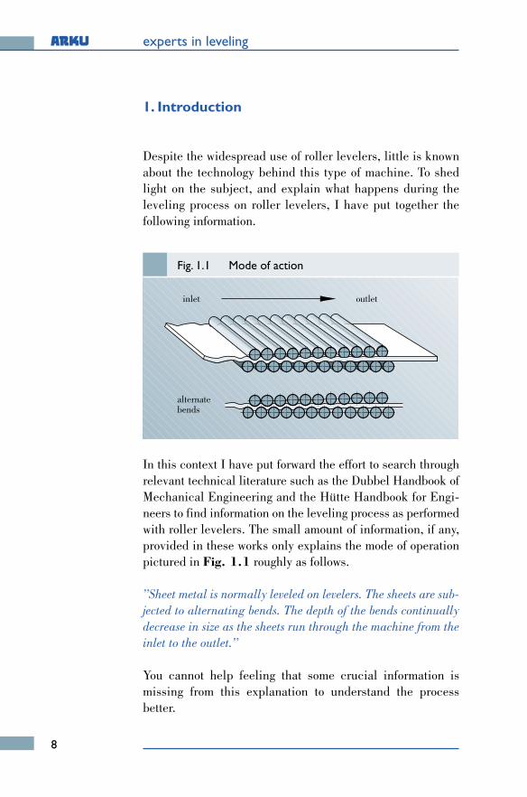
1. Introduction
Despite the widespread use of roller levelers, little is knownabout the technology behind this type of machine. To shedlight on the subject, and explain what happens during theleveling process on roller levelers, I have put together thefollowing information.
In this context I have put forward the effort to search throughrelevant technical literature such as the Dubbel Handbook ofMechanical Engineering and the Hütte Handbook for Engi-neers to find information on the leveling process as performedwith roller levelers. The small amount of information, if any,provided in these works only explains the mode of operationpictured in Fig. 1.1 roughly as follows.
”Sheet metal is normally leveled on levelers. The sheets are sub-jected to alternating bends. The depth of the bends continuallydecrease in size as the sheets run through the machine from theinlet to the outlet.”
You cannot help feeling that some crucial information ismissing from this explanation to understand the processbetter.
Fig. 1.1 Mode of action
inlet outlet
alternatebends

9
leveling with roller levelers
Perhaps the following classification of the roller leveling me-thod can help:
”Roller leveling is classified under bending in the field offorming technology. It is a bending process with rotating tools,whereby the roll axes can be aligned either perpendicular or in-clined to the bending plane.”
This information may not be much more illuminating, buttaken together the two statements make one thing clear:
For this to happen, however, forces have to be applied to thematerial by the leveling rollers.
As the next step toward understanding the leveling principlewe should consider the effects of these forces on the processmaterials, which normally are made of metal.
”The process materialis bent!”

10

leveling with roller levelers
11
Principlesof materials science 2
2.1 Tension and compression
2.2 Bending

12
experts in leveling
2. Principles of materials science
Therefore, we now want to look into the question of how metallicobjects behave when they are subjected to a load. In this case ourconsiderations will be limited to applications of force whichresult in tensile stress, compressive stress and bending stress.
2.1 Tension and compression
A series of predefined tests based on purely phenomenologi-cal methodology is normally performed to analyze the behaviorof objects under load. The tensile test presented in Fig. 2.1supplies the most important characteristic: values for asses-sing a material.
In the tensile test a test rod with cross-section A is loaded witha tensile force F. Depending on the magnitude of this tensileforce, the rod stretches by the amount Δl as indicated in the il-lustration.
Fig. 2.1 Tensile test
test rod
sliced
F F
Δll
F
;FAΔllσε
======
tensile force [N]cross section [mm2]change in length [mm]sample length [mm]tension [N/mm2]elongation [1]
ε =Δl
lσ =
F
A

13
leveling with roller levelers
If you imagine the object cut open somewhere perpendicularto the tensile force F, then said force is distributed inside theobject over the entire cross-sectional area. This distribution isreferred to as stress and is indicated by small arrows distribu-ted over the cross-section.
In correlation with the external tensile force F, this stress is re-ferred to as the tensile stress σ. It is the force F in relation tothe test specimen cross-section A in numerical terms.
It is customary to relate the change of length Δ1 to the origi-nal test specimen length 1. The ratio of Δ1 to 1 is referred toas the elongation ε.
ε [%]εpl1
εpl2
Rm
σZRe
0
S 1
2
Z
Fig. 2.2 Result tensile test
construction steel
σ [N/mm2]
ReσZ
==
yield pointrupture strength
Rm = tensile strength

14
experts in leveling
Let us first consider the zone marked by the straight line OS.If the forces or stresses are kept below the limit value Re of theyield point, then only elastic strains occur. After these stressesare removed, the strains disappear completely and the objectsprings back. Stress and strain are directly proportional toeach other, and the relationship is expressed by Hooke's Lawin the equation.
The proportionality constant E is the modulus of elasticity ofthe material.
If the stress is increased so much as to reach the yield strengthRe, then the yield range of the material is entered. This zoneis marked by the horizontal straight line. The elastic strainsare now accompanied by measurable plastic strains. Henceelastic and plastic strain fractions exist side by side, resultingalways in a total strain.
Spring-back also occurs, for example, if a test specimen is un-loaded from point "1". The elastic strain returns to zero alongthe dot-and-dash line parallel to the Hookian straight line,but a plastic strain εpl1 arises as a permanent strain of the testrod.
σ = E · ε
εtotal = εel + εpl
What you now get from the tensile test in purely qualitativeterms is the simplified result presented in Fig. 2.2, which isvalid for example for a standard construction steel. In thisfigure the stress σ is plotted as a function of the elongation ε.

15
leveling with roller levelers
This yield range characterized by the yield strength Re is nowfollowed by the so-called hardening range. Here the stress in-creases with homogenous straining of the specimen until themaximum value, the tensile strength Rm, is reached. Then thespecimen necks with a local load dip and fractures at point Z,the rupture strength σz.
If a specimen is unloaded for example from point "2" in thehardening zone, then the elastic elongation returns to zero andεpl2 arises as a permanent elongation.
As is evident from Fig. 2.3, not all metallic materials displaythe hardening curve just shown.
ε [%]
σ [N/mm2]
Fig. 2.3 Hardening curve metallic material
0elongation
tens
ion
c
a
b
d
a: brittle steelb: mild steel
c: gray cast irond: copper

16
experts in leveling
The hardening curves for a brittle steel, a soft steel, grey castiron and soft-annealed copper are presented in this figure.
All the curves have a more-or-less distinctive linear startingzone. In other words a Hookian straight line. Brittle steel, greycast iron and copper have practically no yield point, i.e. thetransition from the elastic to the plastic-plastic deformation zo-ne is continuous. With such behavior the yield point Re isreplaced by the proof stress Rpo,2. This is the stress which gi-ves rise to a permanent strain of 0.2 %. Compared to copper orsoft steel, brittle steel has a hardly distinctive plastic zone.Grey cast iron displays practically no noteworthy plastic de-formation. Soft steel displays the behavior already discussedat the beginning.
It is also important to know how a material behaves under com-pressive loading in practice. In this case, the compression testsupplies the characteristic values needed for assessing a com-pressive stress.
Fig. 2.4 shows the hardening curve for tension and compres-sion, again using the example of a standard structural steel.
The compressive stress σd affects a shortening, i.e. compres-sion εd of the specimen. As a rule, the ratio of σd to εd is thesame as in the tensile test, namely the modulus of elasticity E.In other words, Hooke's Law also applies in the compressionzone.
In the compression zone the yield strength Re is replaced bythe compressive yield point Red, which in the case of ductilematerials characterizes the beginning of plastic deformations.Re and Red concur as a rule.
A value for the compressive strength corresponding to the ten-sile strength can be determined only for brittle materials. Aductile material can be crushed practically without destruc-tion.

17
leveling with roller levelers
After this review of loading by tension and compression wenow want to consider loading by bending.
2.2 Bending
Fig. 2.5 shows a straight piece of sheet metal which issupported at both ends and loaded at the centre by a force Facting perpendicular to it. Under the action of the force, as abending moment, the metal sheet bends as indicated by thethin line and stresses arise.
ε [%]
σ [N/mm2]
εd [%]
σd
Fig. 2.4 Hardening curve for tension and compression
elongation
buckling
tension
compression
Re
Red
Hookian straight line: σd
εd
σε
= E=

18
experts in leveling
If we focus on a bent piece of the metal sheet as shown inFig. 2.6, then the following applies:
Inner-lying fibres of the material are compressed; outer-lyingfibres are elongated. In between is a fibre which is neithercompressed nor strained. This fibre is referred to as a neutralfibre.
For better understanding let us consider the tube with outer ra-dius R and inner radius r drawn along side. It is clear that the
pipe
cut outpipe part
r
R
ρn
fiber
neutral
ρ n
bucklinginside
outsideelongation
Fig. 2.6 Bend part
Fig. 2.5 Bending load
sheetF

19
leveling with roller levelers
inner circle with radius r has a smaller circumference than theouter circle with radius R. In relation to the circle with radiusρn lying in between we can say that the inner circle is com-pressed and the outer circle is elongated.
Of course, what applies for the tube as a whole must alsoapply to a piece cut out of the tube. In terms of our bent pieceof metal sheet, ρn is the current bending radius of the neutralfibre.
Fig. 2.7 presents the stresses and elongated which ariseduring the bending. It is assumed that the neutral fibre runs
outside
inside
neutral
Fig. 2.7 Elastical bending load
ρns = sheet thickness
compression
s/2
s/2
tension
0
n
ε (n)
elongation: ε(n) = ρn
nedge elongation: εR =
edge stress: σR = E · εR = E ·
Hooke‘s law: σ = E · ε stress: σ(n) = E · ε(n)
2s( n
2s (
2ρn
s
2ρn
s

20
experts in leveling
in the middle of the cross-section. The strains and compres-sions of the individual fibres increase linearly with the distan-ce from the neutral fibre. This relationship is described bythe above equation where n is the distance from the neutralfibre. It should be noted that compressions are negativestrains.
Hooke's Law applies for elastic loading, i.e. stress and elon-gation are linked together in a linear relationship. The resultis a stress curve (called the bending stress distribution) with alinear distribution according to the elongation. The inner-ly-ing compressed fibres are exposed to a compressive stresswhereas the outer-lying strained fibres are exposed to a tensi-le stress. At the edges the stresses and elongation are greatestin terms of quantity and they are referred to as edge stressesσRand edge elongation εR.
It should be noted that the neutral fibre then lies in the midd-le of the cross-section if no additional tensile or compressiveload exists along with the bending load.
If the maximum values of the edge stresses σR remain underthe yield strength Re, then the bent part springs back to its ori-ginal straight position after the force F is removed.
If the force F is increased (and with it, it's bending momentMb) such that the above limit value Re is reached and excee-ded, then plastic elongation arise first in the edge fibres. Asthe bending moment increases, so deeper lying fibres are gra-dually affected and are likewise plastically deformed. Howe-ver, the plastic deformation is always hindered by fibres lyingfurther inside which are still elastically deformed.
This elastic-plastic bending load has the stress and elongationcharacteristic presented qualitatively in Fig. 2.8.
It is evident that a stress increasing linearly with the distancefrom the neutral fibre exists only in zones near the middle of

21
leveling with roller levelers
the metal sheet. In the edge zones there arises the yield stresswhich corresponds to the respective total strain.
The dot-and-dash line shows the characteristic of the total lon-gitudinal elongation εtotal.It continues to increase linearly withthe distance from the neutral fibre.
If the force F is now removed, the sheet metal will again springback but will no longer reach its original straight position.A permanent bend with corresponding residual stresses is for-med.
Conversely, such a bent metal sheet can be restored to its flatcondition by corresponding counter-bending with due accountfor spring-back. This is a decisive point - missing up until now- for our understanding of the working principle:
”Counter-bendingwith consideration for
spring-back!”
outside
inside
neutral
Fig. 2.8 Elastic-plastic bending load
ρn
0
n
εges
Mb
compression
tension
Mb

22
experts in leveling
In other words, the process of bending and counter-bendingcorresponds to the working principle of roller levelers. It re-quires the yield point of the process material to be exceededwhile, at the same time, ensuring the material is not damagedin any way. However, damage easily arises, for example withbrittle materials, because cracks can develop on the surfacefrom bending beyond the elastic limit.
From this, it is clear that materials with pronounced yieldpoint and with a sufficiently large gap between yield strengthand tensile strength are suitable for leveling.
As a rule of thumb we could say:
Now we want to leave our excursion into materials science andturn to the question of the interaction between leveler and thematerial to be leveled.
”What can be bentcan also be leveled!”