
2H operation manual - atitest.comatitest.com/wp-content/uploads/2016/05/2H-IQ-OQ-RevA.pdf · 11403...
27
IQ/OQ Installation / Operation Qualification MANUAL for the 2H and 2H-N Aerosol Photometers Air Techniques International Division of Hamilton Associates, Inc 11403 Cronridge Drive Owings Mills, MD 21117 USA TEL: 410 363-9696 FAX: 410 363-9695 www.atitest.com [email protected] IQ/OQ 2H, 2H-N Revision 0
Transcript of 2H operation manual - atitest.comatitest.com/wp-content/uploads/2016/05/2H-IQ-OQ-RevA.pdf · 11403...

IQ/OQ
Installation / Operation Qualification MANUAL
for the
2H and 2H-N Aerosol Photometers
Air Techniques International
Division of Hamilton Associates, Inc
11403 Cronridge Drive Owings Mills, MD 21117 USA
TEL: 410 363-9696 FAX: 410 363-9695
www.atitest.com [email protected]
IQ/OQ 2H, 2H-N Revision 0

Revision A 2
This page intentionally left blank
Revision A 3
Table of Contents
1 INSTALLATION QUALIFICATION 6
1.1 Requirements 6
1.2 Unpacking 6
2 SETUP 7
2.1 Locations & Functions 7
2.2 Front Panel Controls and Indicators 8
2.3 Scanning Probe connections 8
2.4 Rear Panel Connections 9
2.5 Side Connection 10
3 OPERATIONAL QUALIFICATION 11
3.1 Initialization 11
3.2 Setup Parameters 11
3.3 Changing Setup Parameters 12
3.4 Setting Up the Alarm Functions 17
3.5 Changing the Reference 17
3.6 UPSTREAM AEROSOL Measurements (DOP or PAO) 18
3.7 Measuring % Leakage - User Defined Reference (USER) 18
3.8 Testing with the 2H 19
3.9 Verifying the Upsream Concentration During Test 19
4 MAINTENANCE 20
4.1 Weekly 20
4.2 Annually 20
4.3 General Maintenance procedures 20
4.4 Recommended Spare Parts 20
4.5 Cleaning the TDA-2SP Scanning Probe Screens 21
4.6 Replacing the Main Power Fuses 21
Revision A 4
4.7 Replacing the HEPA Exhaust Filter 21
A-1. SPECIFICATIONS 22
A-2. TROUBLESHOOTING 23
A-3. QUICK SETUP REFERENCE 24
A-4. RS-232 COMMUNICATION 26
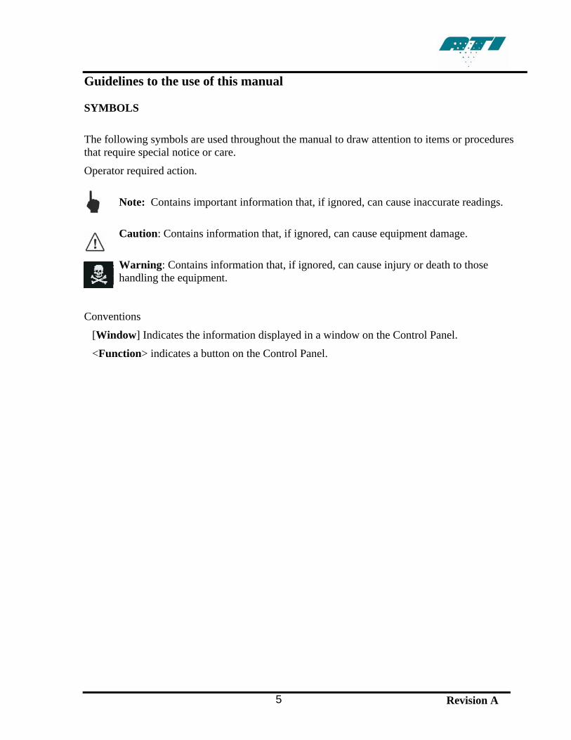
Guidelines to the use of this manual SYMBOLS The following symbols are used throughout the manual to draw attention to items or procedures that require special notice or care.
Operator required action.
Note: Contains important information that, if ignored, can cause inaccurate readings.
Caution: Contains information that, if ignored, can cause equipment damage.
Warning: Contains information that, if ignored, can cause injury or death to those handling the equipment.
Conventions
[Window] Indicates the information displayed in a window on the Control Panel.
<Function> indicates a button on the Control Panel.
Revision A 5
1 INSTALLATION QUALIFICATION
1.1 REQUIREMENTS
NOTE: High ambient temperatures may create instability in the readings. The 2H requires the following for proper operation: • Stable electrical power at 90/240 VAC, single phase, 50/60 Hz, 5 amps. • Environment Operating Range: 35° to105° Fahrenheit (1.6° to 40.6° Celsius)
with less than 75% relative humidity. 1.2 UNPACKING
NOTE: Save all packaging material for future use. Carefully unpack and remove the 2H Aerosol Photometer and all accessories from its shipping container. If the instrument has been damaged in transit, notify the shipper immediately. Make sure the following items are included with both the 2H (9300133) and the 2HHP (9300134): 1) 1 power cord, 6700001 (120 VAC) or T2E0-0063 (220 VAC) 2) 12 feet of clear PVC tubing, 5200116 3) Operating Manual, 1800110 4) Calibration certificate The following items are optional. Check the order packing slip. 1) Shipping case, 9300145 2) 2H-SP Scanning Probe, complete, 9300144
a) 1 round isokinetic nozzle (red), T2E0-0572 b) 1 rectangular isokinetic nozzle (blue), T2E0-0798 c) 1 NSF 1” round nozzle (black), T2E0-0005 d) 1 Scanning probe, T2SP-0881
If any of these items are on the order packing slip but missing from the shipment, contact ATI immediately at:
Air Techniques International Division of Hamilton Associates
11403 Cronridge Drive Owings Mills, Maryland 21117-2247 U.S.A.
Tel: 410 363-9696 Fax: 410 363-9695 www.atitest.com
Revision A 6
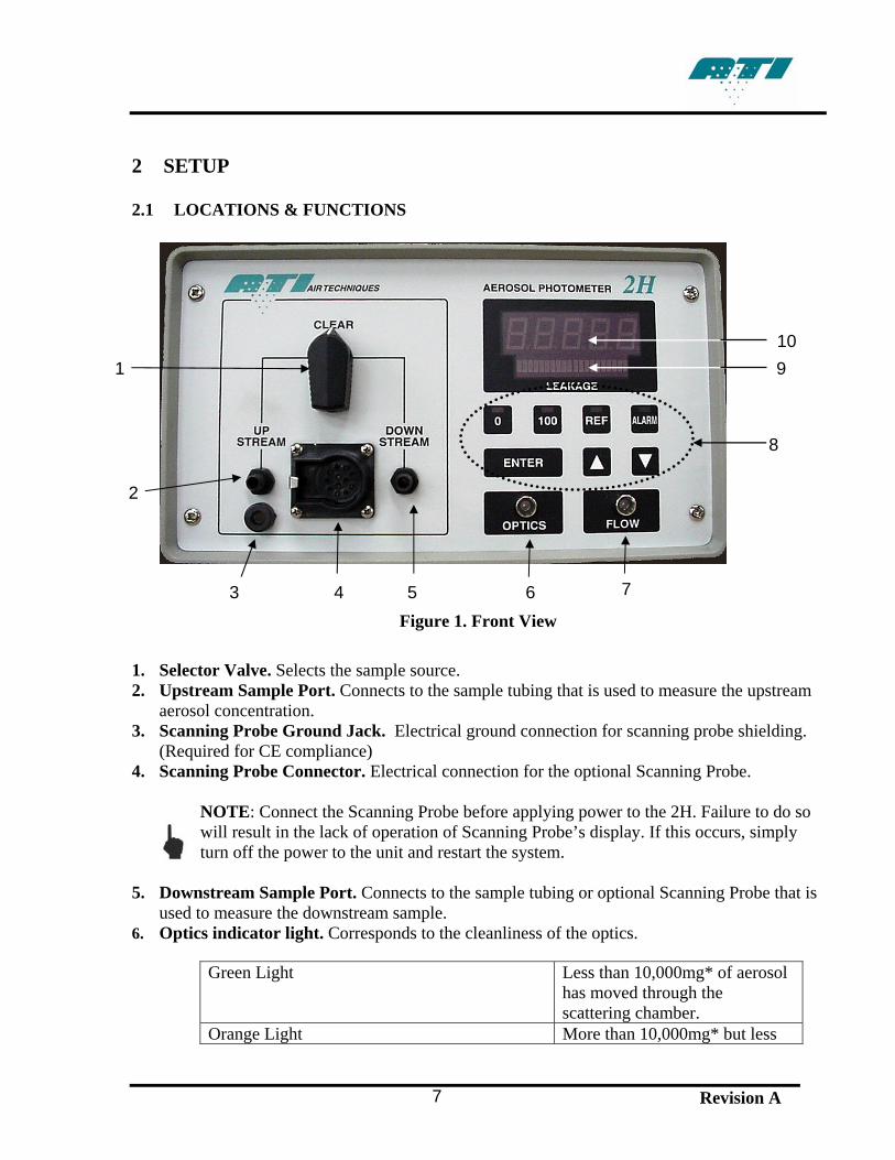
2 SETUP
2.1 LOCATIONS & FUNCTIONS
101 9
8
2
7 3 4 5 6Figure 1. Front View
1. Selector Valve. Selects the sample source. 2. Upstream Sample Port. Connects to the sample tubing that is used to measure the upstream
aerosol concentration. 3. Scanning Probe Ground Jack. Electrical ground connection for scanning probe shielding.
(Required for CE compliance) 4. Scanning Probe Connector. Electrical connection for the optional Scanning Probe.
NOTE: Connect the Scanning Probe before applying power to the 2H. Failure to do so will result in the lack of operation of Scanning Probe’s display. If this occurs, simply turn off the power to the unit and restart the system.
5. Downstream Sample Port. Connects to the sample tubing or optional Scanning Probe that is
used to measure the downstream sample. 6. Optics indicator light. Corresponds to the cleanliness of the optics.
Green Light Less than 10,000mg* of aerosol has moved through the scattering chamber.
Orange Light More than 10,000mg* but less
Revision A 7
than 17,000mg* of aerosol has moved through the scattering chamber.
Red Light More than 17,000mg* of aerosol has moved through the scattering chamber. Servicing of the unit is highly recommended.
* Note: These values are approximate. Actual mass may vary with different airflow rates and aerosols.
7. Flow indicator light. Displays green when flow is within 5% of 1 CFM, yellow when flow is from 5% to 10% of 1 CFM, and red when flow is more than 10% above or below 1 CFM.
8. Function Keys. Used for setting operating parameters and initiating program routines 9. Bar Graph Display. Displays an analog representation of the % leakage to aid in isolating
leaks. 10. Front Panel Display. Indicates % leakage readings and error messages. 2.2 FRONT PANEL CONTROLS AND INDICATORS The front panel contains seven pressure-activated function keys. The <0>, <100>, <REF>, and <ALARM> keys each contain a red LED to indicate the state of the switch or to prompt the operator. The <Δ> and <∇> keys are used to scroll among selections as they are shown on the % LEAKAGE display. The <ENTER> key serves as the command key for sending information to the processor and for initiating or stopping system routines. The <Δ>, <∇>, and <ENTER> keys contain no indicator LED. The % LEAKAGE display is an array of high-visibility LEDs that forms a display screen. The Front Panel Display shows alphanumeric messages. Below it is a Bar Graph Display that gives a visual indication of internal photometer cycling or an analog representation of quantity or percentage. The Scanning Probe contains an unlabeled display on the pistol grip that is a half-scale duplicate of the % LEAKAGE Indicator. The two displays are driven by the same electronics and will always read exactly the same. The Selector Valve, the Scanning Probe connector, and the two barbed fittings are discussed later. 2.3 SCANNING PROBE CONNECTIONS If using the 2H with the Scanning Probe, connect the probe’s electrical connector to the 12-pin connector on the front panel of the 2H before applying power to the photometer. Otherwise, the display on the Scanning Probe will not function. Connect the probe’s sampling hose to the barbed DOWNSTREAM fitting to the right of the 12-pin connector. The cable and sampling hose are
Revision A 8
bound as a single, flexible umbilical. Select the appropriate probe nozzle and screw it onto the threaded end of the flexible portion of the Scanning Probe.
Note: When using the TDA-2SP Scanning Probe with the 2H, the probe must be connected to the photometer before the power is turned on. Otherwise the 2H will not detect the probe and no display will be observed on the pistol grip. If this occurs, switch the power off, verify that the probe is connected properly, and then switch the power back on.
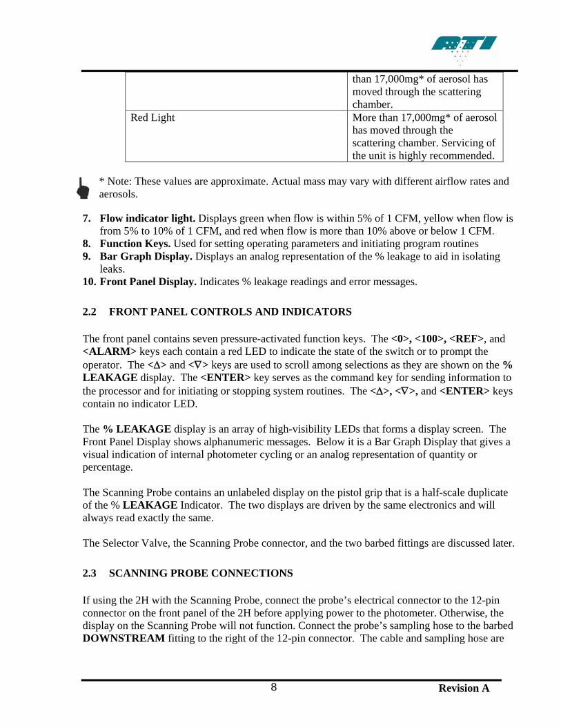
2.4 REAR PANEL CONNECTIONS
32 4 1 5 6
Figure 2. Rear Panel
1. Cooling Fan – Maintains airflow through the unit’s enclosure to stabilize electronics. 2. Power Connector with –Connects to the Power Cord. 3. Fuse Block – Contains 2-amp fuse and spare fuse. 4. Power Switch – Rocker Switch. Turns system power on and off. 5. Serial Number Label – Lists the model and serial number. 6. Vacuum Pump Exhaust – Allows a filter to be installed to eliminate particulate
emissions. The rear panel contains a recessed, 3-pronged male Power Connector, with an integral fuse block and power switch, and a Vacuum Pump Exhaust HEPA Filter.
Revision A 9
CAUTION: The 2H should always be positioned so that the Power Switch, located on the rear panel, is readily accessible in the event the unit needs to be powered off quickly.
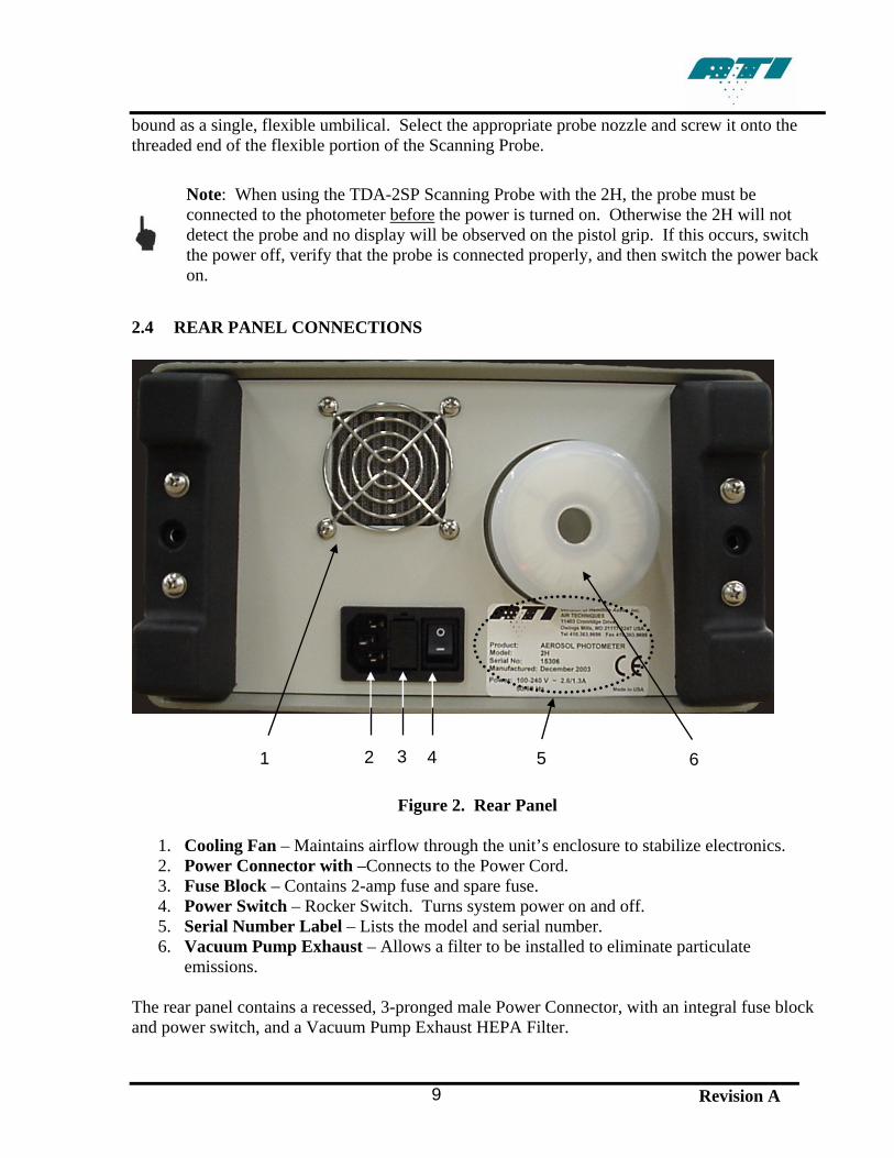
The Power Connector accepts the female end of the Power Cord that comes with the unit. The internal power supply is a universal supply that can operate at either 50 or 60 Hz and with any voltage from 90 to 240 volts, for use in virtually all countries. Therefore, any plug with the correct female end (IEC-320 standard) may be attached to the unit and the universal power supply will automatically switch to use the supplied input power. The Vacuum Pump Exhaust HEPA Filter is provided so that the sensitive environments of cleanrooms can be maintained. The air expelled by the unit is continually filtered of all particulate matter generated by testing aerosols and the unit using this HEPA exhaust system. 2.5 SIDE CONNECTION
Figure 3. RS-232 Port
RS-232 Port. % Leakage data is continuously sent via the RS-232 port as it is updated on the Front Panel Display, approximately once per second. It is recommended that this data be logged to either one of ATI’s data acquisition systems, the DAS1 or the DAS2. Contact ATI or your local representative to learn more about data logging options. If using a terminal program to receive this data, a straight cable must be used (as opposed to a null modem cable). If using a Pocket PC (PPC) to receive data, the type of cable will depend upon the brand of PPC. Contact ATI customer service for complete details.
Revision A 10
Revision A 11
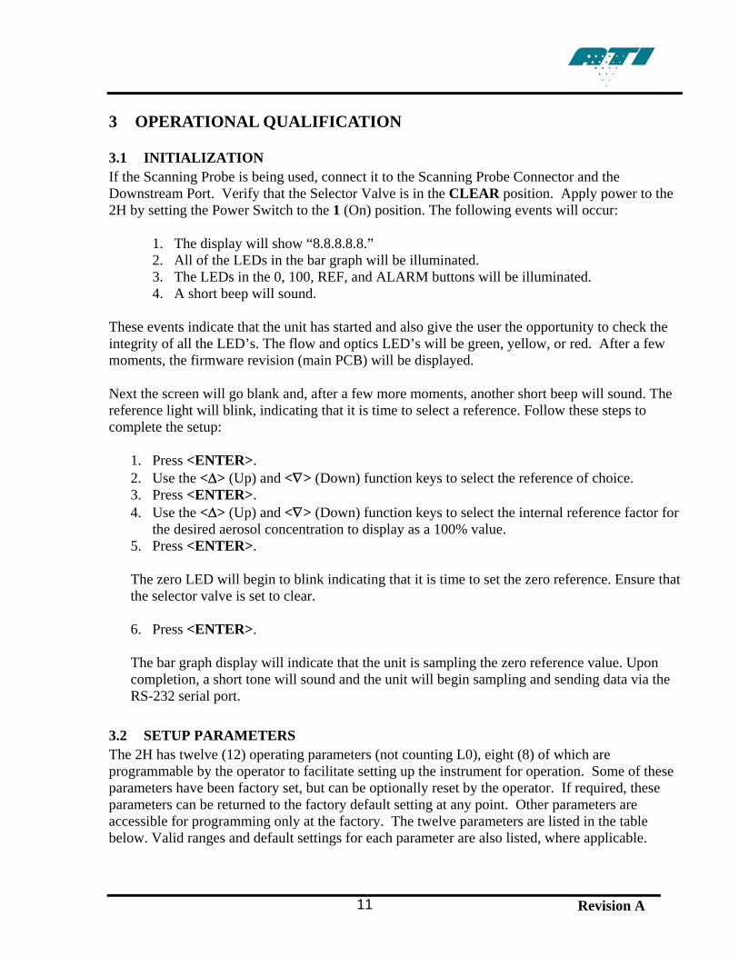
3 OPERATIONAL QUALIFICATION
3.1 INITIALIZATION If the Scanning Probe is being used, connect it to the Scanning Probe Connector and the Downstream Port. Verify that the Selector Valve is in the CLEAR position. Apply power to the 2H by setting the Power Switch to the 1 (On) position. The following events will occur:
1. The display will show “8.8.8.8.8.” 2. All of the LEDs in the bar graph will be illuminated. 3. The LEDs in the 0, 100, REF, and ALARM buttons will be illuminated. 4. A short beep will sound.
These events indicate that the unit has started and also give the user the opportunity to check the integrity of all the LED’s. The flow and optics LED’s will be green, yellow, or red. After a few moments, the firmware revision (main PCB) will be displayed. Next the screen will go blank and, after a few more moments, another short beep will sound. The reference light will blink, indicating that it is time to select a reference. Follow these steps to complete the setup:
1. Press <ENTER>. 2. Use the <Δ> (Up) and <∇> (Down) function keys to select the reference of choice. 3. Press <ENTER>. 4. Use the <Δ> (Up) and <∇> (Down) function keys to select the internal reference factor for
the desired aerosol concentration to display as a 100% value. 5. Press <ENTER>. The zero LED will begin to blink indicating that it is time to set the zero reference. Ensure that the selector valve is set to clear. 6. Press <ENTER>. The bar graph display will indicate that the unit is sampling the zero reference value. Upon completion, a short tone will sound and the unit will begin sampling and sending data via the RS-232 serial port.
3.2 SETUP PARAMETERS The 2H has twelve (12) operating parameters (not counting L0), eight (8) of which are programmable by the operator to facilitate setting up the instrument for operation. Some of these parameters have been factory set, but can be optionally reset by the operator. If required, these parameters can be returned to the factory default setting at any point. Other parameters are accessible for programming only at the factory. The twelve parameters are listed in the table below. Valid ranges and default settings for each parameter are also listed, where applicable.
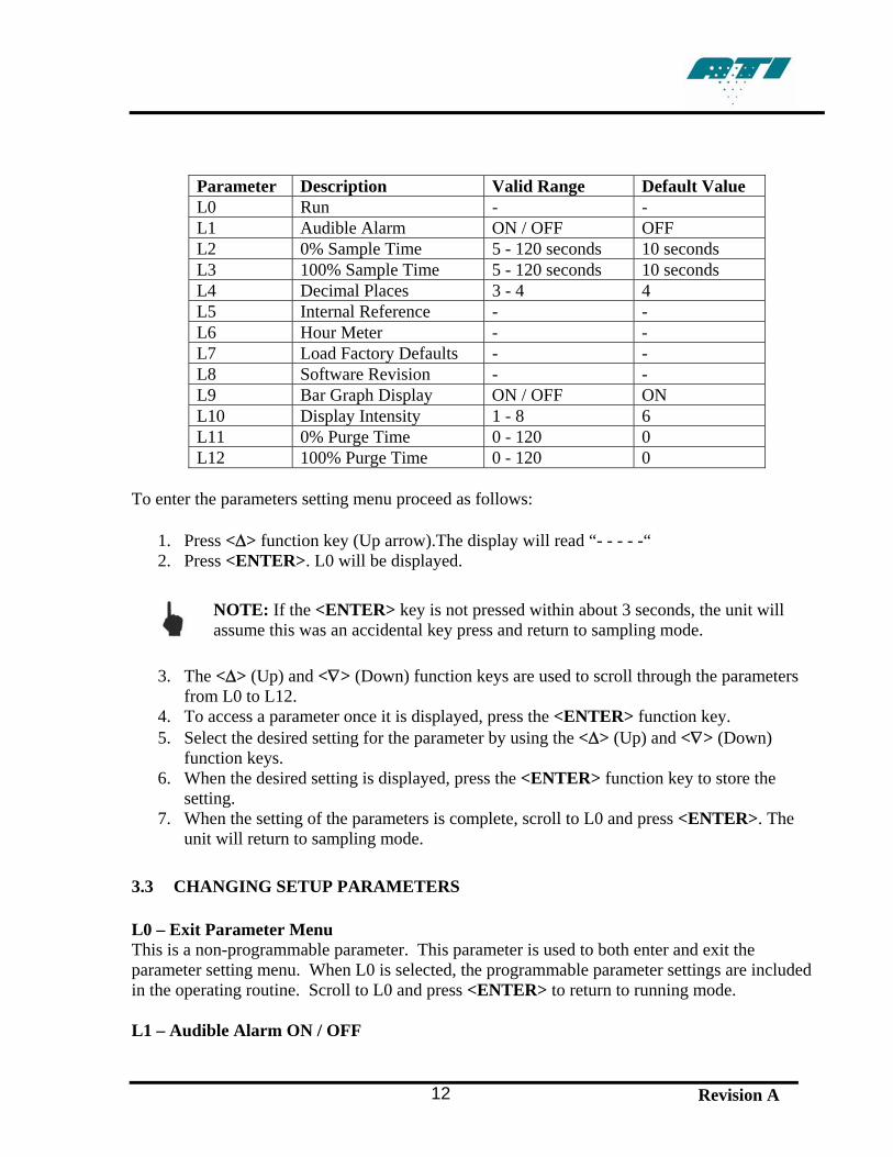
Parameter Description Valid Range Default Value L0 Run - - L1 Audible Alarm ON / OFF OFF L2 0% Sample Time 5 - 120 seconds 10 seconds L3 100% Sample Time 5 - 120 seconds 10 seconds L4 Decimal Places 3 - 4 4 L5 Internal Reference - - L6 Hour Meter - - L7 Load Factory Defaults - - L8 Software Revision - - L9 Bar Graph Display ON / OFF ON L10 Display Intensity 1 - 8 6 L11 0% Purge Time 0 - 120 0 L12 100% Purge Time 0 - 120 0
To enter the parameters setting menu proceed as follows:
1. Press <Δ> function key (Up arrow).The display will read “- - - - -“ 2. Press <ENTER>. L0 will be displayed.
NOTE: If the <ENTER> key is not pressed within about 3 seconds, the unit will assume this was an accidental key press and return to sampling mode.
3. The <Δ> (Up) and <∇> (Down) function keys are used to scroll through the parameters
from L0 to L12. 4. To access a parameter once it is displayed, press the <ENTER> function key. 5. Select the desired setting for the parameter by using the <Δ> (Up) and <∇> (Down)
function keys. 6. When the desired setting is displayed, press the <ENTER> function key to store the
setting. 7. When the setting of the parameters is complete, scroll to L0 and press <ENTER>. The
unit will return to sampling mode.
3.3 CHANGING SETUP PARAMETERS L0 – Exit Parameter Menu This is a non-programmable parameter. This parameter is used to both enter and exit the parameter setting menu. When L0 is selected, the programmable parameter settings are included in the operating routine. Scroll to L0 and press <ENTER> to return to running mode. L1 – Audible Alarm ON / OFF
Revision A 12
Revision A 13
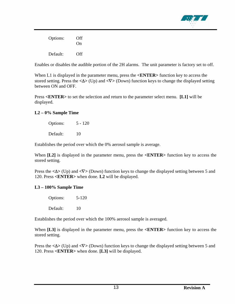
Options: Off
On
Default: Off Enables or disables the audible portion of the 2H alarms. The unit parameter is factory set to off. When L1 is displayed in the parameter menu, press the <ENTER> function key to access the stored setting. Press the <Δ> (Up) and <∇> (Down) function keys to change the displayed setting between ON and OFF. Press <ENTER> to set the selection and return to the parameter select menu. [L1] will be displayed. L2 – 0% Sample Time
Options: 5 - 120
Default: 10 Establishes the period over which the 0% aerosol sample is average. When [L2] is displayed in the parameter menu, press the <ENTER> function key to access the stored setting. Press the <Δ> (Up) and <∇> (Down) function keys to change the displayed setting between 5 and 120. Press <ENTER> when done. L2 will be displayed. L3 – 100% Sample Time
Options: 5-120
Default: 10 Establishes the period over which the 100% aerosol sample is averaged. When [L3] is displayed in the parameter menu, press the <ENTER> function key to access the stored setting. Press the <Δ> (Up) and <∇> (Down) function keys to change the displayed setting between 5 and 120. Press <ENTER> when done. [L3] will be displayed.

L4 – Decimal Places to be displayed
Options: 3 or 4
Default: 4
This parameter is used to select either 3 or 4 decimal places on the % Leakage Display. When [L4] is displayed in the parameter menu, press the <ENTER> function key to access the stored setting. Press the <Δ> (Up) and <∇> (Down) function keys to move the displayed setting between 3 and 4 on the display (3=0.001%, 4=0.0001%). Press <ENTER> to set the selection and return to the parameter select menu. [L4] will be displayed. L5 – Aerosol Reference Selection
Options: DOP, PAO, USER, HIGH
Default: DOP
When [L5] is displayed in the parameter menu, press the <ENTER> function key to access the stored setting.
Note: Refer to section 4.5, page 20 “changing the reference” to change the selection or reestablish internal reference.
See A-7 for correction factors to be used in conjunction with other challenge aerosols. Press <ENTER> to set the selection and return to the parameter select menu. [L5] will be displayed. L6 – Hour Meter
Options: N/A
Default: N/A
Displays the total running time for the unit.
Revision A 14
Revision A 15
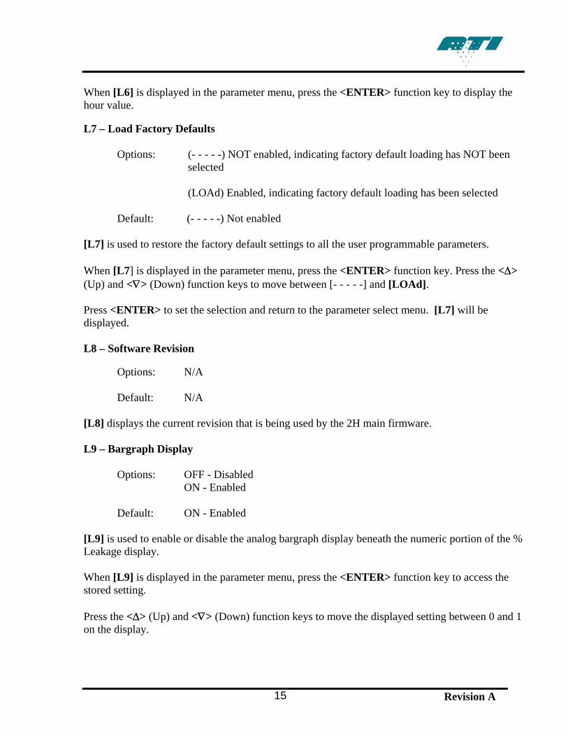
When [L6] is displayed in the parameter menu, press the <ENTER> function key to display the hour value. L7 – Load Factory Defaults
Options: (- - - - -) NOT enabled, indicating factory default loading has NOT been selected
(LOAd) Enabled, indicating factory default loading has been selected
Default: (- - - - -) Not enabled
[L7] is used to restore the factory default settings to all the user programmable parameters. When [L7] is displayed in the parameter menu, press the <ENTER> function key. Press the <Δ> (Up) and <∇> (Down) function keys to move between [- - - - -] and [LOAd]. Press <ENTER> to set the selection and return to the parameter select menu. [L7] will be displayed. L8 – Software Revision
Options: N/A Default: N/A
[L8] displays the current revision that is being used by the 2H main firmware. L9 – Bargraph Display
Options: OFF - Disabled ON - Enabled Default: ON - Enabled
[L9] is used to enable or disable the analog bargraph display beneath the numeric portion of the % Leakage display. When [L9] is displayed in the parameter menu, press the <ENTER> function key to access the stored setting. Press the <Δ> (Up) and <∇> (Down) function keys to move the displayed setting between 0 and 1 on the display.
Revision A 16
Press <ENTER> to set the selection and return to the parameter select menu. [L9] will be displayed. L10 – % Leakage Display Intensity
Options: 1-8 Default: 6
[L10] is used to adjust the intensity of the green LED display in the % Leakage display. When [L10] is displayed in the parameter menu, press the <ENTER> function key to access the stored setting. Press the <Δ> (Up) and <∇> (Down) function keys to move the displayed setting between 1 and 8 on the display. Press <ENTER> to set the selection and return to the parameter select menu. [L10] will be displayed. L11 – 0% Purge Time
Options: 0 - 120 Default: 0
Set the length of time for the system to run before taking reading when calculating the zero value. When [L12] is displayed in the parameter menu, press the <ENTER> function key to access the stored setting. Press the <Δ> (Up) and <∇> (Down) function keys to change the displayed setting between 0 and 120 seconds. Press <ENTER> when done. [L12] will be displayed. L12 – 100% Purge Time
Options: 0 - 120 Default: 0
Set the length of time for the system to run before taking reading when calculating the 100% value. When [L12] is displayed in the parameter menu, press the <ENTER> function key to access the stored setting.
Revision A 17
Press the <Δ> (Up) and <∇> (Down) function keys to change the displayed setting between 0 and 120 seconds. Press <ENTER> when done. [L12] will be displayed. 3.4 SETTING UP THE ALARM FUNCTIONS The 2H has an alarm feature which can alert the user when particle concentration exceeds a user-selected % Leakage value. To set the alarm features, perform the following steps:
1. After system initialization, press the <ALARM> function key. 2. The ALARM LED will flash and the current alarm setting ([ON] or [OFF]) will be
displayed. 3. Press the <Δ> (Up) and <∇> (Down) function keys to change the displayed setting. 4. If changing the alarm set point is not desired, the <ENTER> function key may be pressed
to return to sampling mode. If this is the case, press <ENTER> and proceed to step 8. 5. If the alarm set point is to be changed or checked, press the <ALARM> function key
again to enter the set point mode. 6. Press the <Δ> (Up) and <∇> (Down) function keys to change the displayed set point. 7. Press the <ENTER> key two (2) times to return to the unit to sampling mode. 8. Setup of the alarm is now complete. When the measured concentration exceeds the set
point, the display with flash. If the audible alarm parameter (L1) is set to ON, a tone will also be heard.
3.5 CHANGING THE REFERENCE During the initialization sequence immediately following unit startup, the user is required to select a reference. To change the desired reference anytime thereafter, perform the following steps:
1. Press the <REF> function key. 2. The REF LED will flash and the display will go blank. 3. Press the <ENTER> function key. If the <ENTER> key is not pressed within about three
(3) seconds, the unit will return to sampling mode. 4. Use the <Δ> (Up) and <∇> (Down) function keys to select the desired reference. 5. Press the <ENTER> function key. 6. Use the <Δ> (Up) and <∇> (Down) function keys to select the desired internal reference
factor. 7. Press the <ENTER> function key. The zero LED will begin to blink indicating that it is time to set the zero reference. Double check the selector valve is set to clear. 8. Press <ENTER>. The bar graph display will indicate that the unit is sampling the zero reference value. Upon completion, the unit will return to the sampling mode.
3.6 UPSTREAM AEROSOL MEASUREMENTS (DOP OR PAO)
Note: Do not perform the steps in this section until completing section 3.1, Initialization. Note: If there is a concern that the zero baselines may have drifted, the operator may re-zero the instrument at any time by positioning the selector valve to the clear position, pressing the <0> button, and pressing <ENTER>.
WARNING: The unit should be placed on a flat, stable surface with the area to be monitored within reach of the sample lines.
1. Insert the UPSTREAM sample line into the upstream aerosol / air mixture. Note: The sample line should be as close to the upstream side of the filter as possible.
2. Turn the Selector Valve to the UPSTREAM position. This switches the sample airflow to
the UPSTREAM sampling port on the front panel. The % LEAKAGE display indicates the upstream concentration as compared to the reference that was set in the initialization section. Note: Adjust aerosol for desired challenge aerosol concentration.
3.7 MEASURING % LEAKAGE - USER DEFINED REFERENCE (USER)
1. Insert the UPSTREAM sample line into the upstream aerosol/air mixture.
Note: The sample line should be as close to the upstream side of the filter as possible.
2. Turn the Selector Valve to the UPSTREAM position. This switches the sample airflow to the UPSTREAM sampling port on the front panel. The % LEAKAGE display indicates the upstream reading.
3. Press the <100> button and press <ENTER>. The unit will begin scanning for a 100%
reference value.
Note: If error E4 is given then 100% calibration failed. The most likely reason this would happen is if there is not enough aerosol present to take an accurate reading. Press <ENTER> to clear the error. The unit defaults back to the previous reference setting.
4. After the 100% reference value has been successfully captured, the <0> LED will blink,
indicating that the 0% reference must be calibrated.
5. Switch the selector valve to CLEAR and press the <ENTER> button. The unit will scan for the 0% reference value.
Revision A 18
Revision A 19
6. After the unit has finished scanning for the 0% reference, switch the selector valve to
<DOWNSTREAM>. The % LEAKAGE display indicates the concentration as compared to the upstream value.
3.8 TESTING WITH THE 2H After the 100% and 0% baselines have been established, the unit is ready for testing operations. During testing operations, readings may be taken from either the Front Panel Display or the Scanning Probe, lessening operator distraction. Testing is performed as follows:
1. Turn the selector valve to DOWNSTREAM to permit sampling through the Scanning Probe.
2. Pass the end of the probe over the filter being tested at the rate required by the standard or recommended practice being employed.
3. Read and record the data as it is displayed on either the pistol grip of the probe or the Front Panel Display. Once the 100% baseline has been properly defined, the display readings are given directly in % leakage.
Note: Most current standards and recommended practices require leaks of greater than 0.01% to be identified and repaired. 3.9 VERIFYING THE UPSREAM CONCENTRATION DURING TEST
Turn the Selector Valve to the UPSTREAM position. The % LEAKAGE display shows the concentration of the upstream challenge aerosol in percent of upstream calibration.
The photometer is comparing the real-time concentration of the upstream challenge to the concentration of this same source when it was initially used to establish the 100% baseline. In other words, it is comparing the current concentration level to the starting level.
If the reading seems reasonable, normal testing may be resumed by turning the Selector Valve back to the DOWNSTREAM position. If the concentration of the challenge aerosol has changed significantly, the upstream source should be examined for the cause. Once the situation has been corrected, the upstream challenge aerosol should be restarted, stabilized, and then used to re-establish the 100% baseline as described previously.
4 MAINTENANCE
Scheduled Maintenance 4.1 WEEKLY
• Clean the scanning probe screens. These are located on the black and red circular scanning probe nozzles.
• Clean the gross particulate screen located at the base of the flexible scanning probe extension.
• Remove any loose debris from the Scanning Probe and front panel sampling ports. 4.2 ANNUALLY
• Return the 2H to a factory authorized facility for calibration and cleaning. Please contact the ATI Customer Service Department at 410-363-9696 for a return authorization number. A service date will be scheduled for your instrument at that time.
A Return Authorization can also be obtained using ATI’s website or by sending an e-mail requesting service information to [email protected]. A customer service representative will process your information and contact you with a Return Authorization, necessary instructions and information within 48 hours. 4.3 GENERAL MAINTENANCE PROCEDURES The 2H Aerosol Photometer is a sturdy, solid-state electronic instrument designed to hold up under extended field use. The only moving parts are the vacuum pump, the Selector Valve and the ventilating fan at the rear of the chassis. Field level maintenance is limited to replacement of the HEPA exhaust filter and the fuse. Procedures for these operations are contained in this section.
NOTE: The internal electronics are not user serviceable. Any electronic problems must be analyzed and repaired at an authorized service center.
At present, there is no error message or indication on the front panel that the scattering chamber light source is not working. If the scattering chamber light source has burned out, the operator will witness a lack of response on the unit’s % LEAKAGE display.
4.4 RECOMMENDED SPARE PARTS Spare components are not supplied with the 2H or the 2H-N nuclear unit and must be ordered separately. See section A-4 for a list of recommended spare parts that may be purchased in kit form or individually. These lists include only parts replaceable by the user in the field. Other repairs requiring instrument or component recalibration must be performed at an ATI service center.
Revision A 20
Revision A 21
4.5 CLEANING THE TDA-2SP SCANNING PROBE SCREENS The TDA-2SP Scanning Probe is a rugged, low maintenance device. The probe contains a course wire screen near the base of the flexible neck to prevent fibers and large particles from being drawn into the photometer. In addition, there are screens in each of the two round nozzles that thread onto the flexible neck. The blue rectangular nozzle contains no screen. If the screens accumulate a significant amount of debris and become partially clogged, it can interfere with the airflow and affect the accuracy of the photometer and may put an unnecessary strain on the vacuum pump. It is recommended that all screens be wiped clean with a lint-free cloth before use each day. If the screens are punctured, replace them immediately. Spare nozzles and replacement scanning probe components can be ordered from ATI (see Section A-4). To access the screen in the flexible neck, unscrew the flexible extension from the probe body. A small tool may be necessary to reach into the neck to remove and wipe the surface of the screen. 4.6 REPLACING THE MAIN POWER FUSES Position the 2H with the rear panel readily accessible. Locate the fuse block at the center of the power entry connector. Press the top and bottom tabs toward the center and pull the fuse block straight out from the power entry connector. The two (2) fuses will be exposed for inspection and/or replacement. Replace the fuse block by gently inserting it back into the power entry connector until the tabs snap back into their original location. 4.7 REPLACING THE HEPA EXHAUST FILTER Position the 2H with the rear panel readily accessible. Rotate the HEPA exhaust filter in a counter-clockwise direction until the threads are free of the rear panel bushing. Install the new replacement filter in the same orientation as the filter that was replaced. Care should be taken to avoid cross-threading the filter housing. When installed correctly a cylindrical well should be visible through the filter port. This design directs exhausted airflow to the outside of the filter media core, providing greater surface area and prolonging service life.
Revision A 22
A-1. SPECIFICATIONS
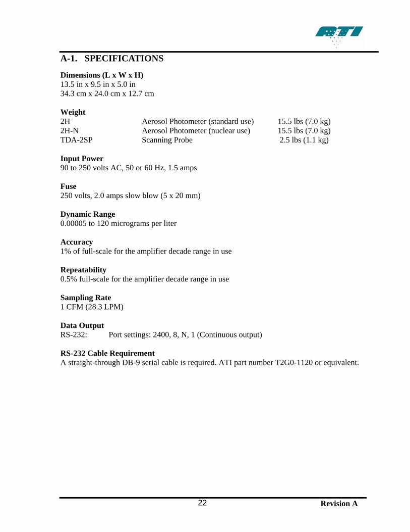
Dimensions (L x W x H) 13.5 in x 9.5 in x 5.0 in 34.3 cm x 24.0 cm x 12.7 cm Weight 2H Aerosol Photometer (standard use) 15.5 lbs (7.0 kg) 2H-N Aerosol Photometer (nuclear use) 15.5 lbs (7.0 kg) TDA-2SP Scanning Probe 2.5 lbs (1.1 kg) Input Power 90 to 250 volts AC, 50 or 60 Hz, 1.5 amps Fuse 250 volts, 2.0 amps slow blow (5 x 20 mm) Dynamic Range 0.00005 to 120 micrograms per liter Accuracy 1% of full-scale for the amplifier decade range in use Repeatability 0.5% full-scale for the amplifier decade range in use Sampling Rate 1 CFM (28.3 LPM) Data Output RS-232: Port settings: 2400, 8, N, 1 (Continuous output) RS-232 Cable Requirement A straight-through DB-9 serial cable is required. ATI part number T2G0-1120 or equivalent.
Revision A 23
A-2. TROUBLESHOOTING
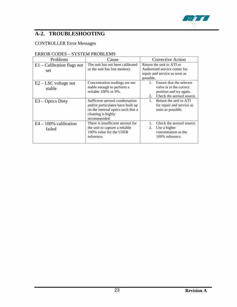
CONTROLLER Error Messages ERROR CODES – SYSTEM PROBLEMS
Problems Cause Corrective Action E1 – Calibration flags not
set The unit has not been calibrated or the unit has lost memory.
Return the unit to ATI or Authorized service center for repair and service as soon as possible.
E2 – LSC voltage not stable
Concentration readings are not stable enough to perform a reliable 100% or 0%.
1. Ensure that the selector valve is in the correct position and try again.
2. Check the aerosol source. E3 – Optics Dirty Sufficient aerosol condensation
and/or particulates have built up on the internal optics such that a cleaning is highly recommended.
1. Return the unit to ATI for repair and service as soon as possible.
E4 – 100% calibration failed
There is insufficient aerosol for the unit to capture a reliable 100% value for the USER reference.
1. Check the aerosol source. 2. Use a higher
concentration as the 100% reference.
Revision A 24
A-3. QUICK SETUP REFERENCE
SETUP
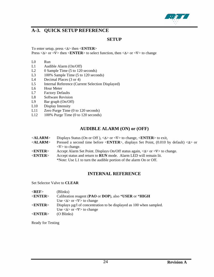
To enter setup, press <Δ> then <ENTER> Press <Δ> or <∇> then <ENTER> to select function, then <Δ> or <∇> to change L0 Run L1 Audible Alarm (On/Off) L2 0 Sample Time (5 to 120 seconds) L3 100% Sample Time (5 to 120 seconds) L4 Decimal Places (3 or 4) L5 Internal Reference (Current Selection Displayed) L6 Hour Meter L7 Factory Defaults L8 Software Revision L9 Bar graph (On/Off) L10 Display Intensity L11 Zero Purge Time (0 to 120 seconds) L12 100% Purge Time (0 to 120 seconds)
AUDIBLE ALARM (ON) or (OFF) <ALARM> Displays Status (On or Off ), <Δ> or <∇> to change, <ENTER> to exit, <ALARM> Pressed a second time before <ENTER>, displays Set Point, (0.010 by default) <Δ> or
<∇> to change. <ENTER> Accept Alarm Set Point. Displays On/Off status again, <Δ> or <∇> to change. <ENTER> Accept status and return to RUN mode. Alarm LED will remain lit. *Note: Use L1 to turn the audible portion of the alarm On or Off.
INTERNAL REFERENCE Set Selector Valve to CLEAR <REF> (Blinks) <ENTER> Calibration reagent (PAO or DOP), also *USER or *HIGH Use <Δ> or <∇> to change <ENTER> Displays µg/l of concentration to be displayed as 100 when sampled. Use <Δ> or <∇> to change <ENTER> (O Blinks) Ready for Testing
Revision A 25
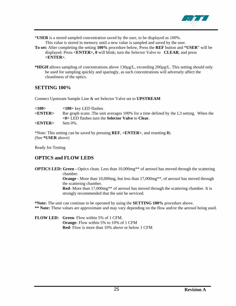
*USER is a stored sampled concentration saved by the user, to be displayed as 100%. This value is stored in memory until a new value is sampled and saved by the user. To set: After completing the setting 100% procedure below, Press the REF button and “USER” will be
displayed. Press <ENTER>, 0 will blink; turn the Selector Valve to CLEAR, and press <ENTER>.
*HIGH allows sampling of concentrations above 130µg/L, exceeding 200µg/L. This setting should only
be used for sampling quickly and sparingly, as such concentrations will adversely affect the cleanliness of the optics.
SETTING 100% Connect Upstream Sample Line & set Selector Valve set to UPSTREAM <100> <100> key LED flashes <ENTER> Bar graph scans .The unit averages 100% for a time defined by the L3 setting. When the
<0> LED flashes turn the Selector Valve to Clear. <ENTER> Sets 0%. *Note: This setting can be saved by pressing REF, <ENTER>, and resetting 0). (See *USER above) Ready for Testing OPTICS and FLOW LEDS OPTICS LED: Green - Optics clean. Less than 10,000mg** of aerosol has moved through the scattering
chamber. Orange - More than 10,000mg, but less than 17,000mg**, of aerosol has moved through
the scattering chamber. Red- More than 17,000mg** of aerosol has moved through the scattering chamber. It is
strongly recommended that the unit be serviced. *Note: The unit can continue to be operated by using the SETTING 100% procedure above. ** Note: These values are approximate and may vary depending on the flow and/or the aerosol being used. FLOW LED: Green- Flow within 5% of 1 CFM.
Orange- Flow within 5% to 10% of 1 CFM Red- Flow is more than 10% above or below 1 CFM
A-4. RS-232 COMMUNICATION
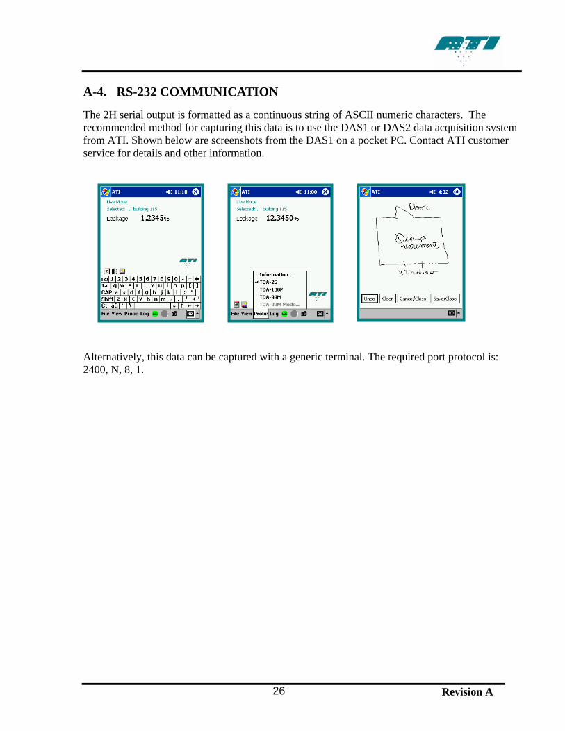
The 2H serial output is formatted as a continuous string of ASCII numeric characters. The recommended method for capturing this data is to use the DAS1 or DAS2 data acquisition system from ATI. Shown below are screenshots from the DAS1 on a pocket PC. Contact ATI customer service for details and other information. Alternatively, this data can be captured with a generic terminal. The required port protocol is: 2400, N, 8, 1.
Revision A 26

Revision A 27
This page intentionally left blank.