29020007 20 final - ComNav Marine · No Autopilot can steer better than its compass ... For larger...
70
Marine Ltd. 1500 Autopilot – Stand Alone System 1510 Autopilot – Network System Operation & Installation Instructions Version 2.0 ComNav R
Transcript of 29020007 20 final - ComNav Marine · No Autopilot can steer better than its compass ... For larger...
Marine Ltd.
1500 Autopilot – Stand Alone System1510 Autopilot – Network System
Operation & Installation InstructionsVersion 2.0
ComNav R

ComNav 1500 / 1510 Autopilot
PN: 29020007
Welcome
Congratulations on your purchase of ComNavMarine’s NX2 1500 Autopilot System! At ComNav,we are proud of our prominence as a leader in thedesign and manufacture of marine Autopilotsystems. Our dedication to performance andreliability will ensure your satisfaction with theComNav 1500. Developed as a result of ComNav’smany years of experience in Autopilot design, the1500 system provides excellent performance andmore features than any other Autopilot in its class.
Yours truly,
Don MorrisVice President OperationsComNav Marine Limited

ComNav 1500 / 1510 Autopilot
PN: 29020007
Warranty Notice
Prior to the installation and/or operation of theequipment, ensure that you read, understandand accept the conditions of the warranties asdetailed in Section 12 of this manual.
Operator’s Warning
The Autopilot will automatically steer yourvessel, however it is only an aid to navigation.Its performance can be affected by manyfactors including equipment failure,environmental conditions and improperhandling or use. This system does not reduceyour responsibility for the control of the vesselwhen underway. You must always be in aposition to monitor the course, supervise theAutopilot, and resume manual control if theneed to do so arises.
Whenever underway, your vessel must beunder the control of a qualified and alertperson.

ComNav 1500 / 1510 Autopilot
PN: 29020007
About This Manual
This manual provides essential information for the safe andreliable operation of the 1501 Autopilot System. You are urged toread this manual in its entirely before you use your Autopilot forthe first time, and to keep it handy until you become thoroughlyfamiliar with the operation of your Autopilot.
Throughout this manual, you will see a number of differenttypefaces used, as well as some distinct phases, or “jargon”.Please take a moment to become familiar with the following terms:
• Each time a push-button is referred to in this manual, the push-button name willappear in bold and CAPITAL letters, e.g. MODE.
• Unless otherwise stated, the push-button presses are momentary.
• Each time a function is mentioned in the text, it will be in brackets and in thesame format, where possible, as displayed, e.g. [HDG] for HeaDinG.
• With the word navigator we mean a GPS, Loran or Decca instrument.
• Which instrument is navigating? By the term navigating, we mean the activeinstrument in which the waypoint memory is used for navigation to calculate thenavigation data, i.e. BTW, DTW etc. There can only be one instrument on theNX2 Network which is keeping the waypoints in memory, but the waypoints canbe reached from all instruments.
ComNav 1500 / 1510 Autopilot
PN: 29020007
1. INTRODUCING THE COMNAV NX2 1500 AUTOPILOT .......................................... 11.1 Capabilities............................................................................................................. 11.2 Principle of Operation............................................................................................. 21.3 Components ........................................................................................................... 31.3.1 Autopilot Instrument Control Head...................................................................... 31.3.2 45 ° Flux Gate Compass..................................................................................... 31.3.3 35 ° Flux Gate Compass..................................................................................... 31.3.4 Distribution Unit .................................................................................................. 31.3.5 Rudder Follower & Linkage ............................................................................... 31.3.6 Reversing Pumpsets........................................................................................... 41.3.7 Linear Drive ........................................................................................................ 41.3.8 Solenoid Valve Drive .......................................................................................... 41.4 Accessories ............................................................................................................ 51.4.1 NX2 Autopilot Instrument Control Head.............................................................. 51.4.2 NX2 Remote Control Instrument......................................................................... 51.4.3 NX2 Analog Rudder Angle Indicator Instrument (RAI) ....................................... 51.4.4 NX2 Multi Control Instrument with Server........................................................... 51.4.5 External Alarm Buzzer ........................................................................................ 51.4.6 NFU Jog Lever.................................................................................................... 5
2. INSTALLATION ......................................................................................................... 62.1 General Comments ................................................................................................ 62.2 Distribution Unit 1500 & 1510................................................................................. 72.2.1 Distribution Unit Connections ........................................................................... 102.2.2 Safety Switch .................................................................................................... 102.2.3 DIP Switches .................................................................................................... 102.2.4 Trim Potentiometers ......................................................................................... 102.3 Control Head ........................................................................................................ 112.4 Flux Gate Compass.............................................................................................. 132.5 Rudder Follower & Linkage ................................................................................. 152.6 Analog Display Rudder Angle Indicator................................................................ 162.7 NMEA 0183 Compass Interface........................................................................... 172.8 LFU101 Full Follow Up (FFU) Tiller Steering ....................................................... 172.9 Reversing Pumpsets ............................................................................................ 172.10 Installing Fittings................................................................................................ 202.11 Mounting the Pumpset...................................................................................... 202.12 Piping the System............................................................................................. 212.13 Filling the System ............................................................................................. 212.14 Linear Drive ...................................................................................................... 212.15 Solenoid Valve Controlled Pumpsets ............................................................... 232.16 Accessories ...................................................................................................... 23
3. ADVANCED OPERATION....................................................................................... 243.1 Adjusting Response (See Calibration Menus)...................................................... 243.2 Rudder [RUD] Function ........................................................................................ 243.3 Sea State [SEA] Function..................................................................................... 243.4 Counter Rudder [CRD] Function .......................................................................... 243.5 Automatic Trim [ATC] Function ............................................................................ 25
4. AUTOPILOT INSTRUMENT CONTROL HEAD OPERATION ................................ 264.1 Instrument Overview ............................................................................................ 264.1.1 Instrument Display............................................................................................. 264.1.2 Instrument Pages and Functions ...................................................................... 26
ComNav 1500 / 1510 Autopilot
PN: 29020007
4.1.3 Instrument Modes ............................................................................................. 264.1.4 Power On/Off .................................................................................................... 264.2 How to Use the Push-Buttons .............................................................................. 274.2.1 MODE................................................................................................................ 274.2.2 LEFT.................................................................................................................. 274.2.3 RIGHT ............................................................................................................... 274.2.4 SET.................................................................................................................... 274.2.5 OFF ................................................................................................................... 274.2.6 Tack................................................................................................................... 274.2.7 Setup Mode ...................................................................................................... 284.2.8 Lighting ............................................................................................................. 28
5. FUNCTION .............................................................................................................. 295.1 Standby Mode ...................................................................................................... 295.2 Autopilot Mode ..................................................................................................... 295.2.1 Activate Automatic Steering ............................................................................ 295.2.2 Turn Off Automatic Steering ............................................................................ 295.2.3 Automatic Steering by Compass ..................................................................... 305.2.4 Automatic Steering by Navigator ...................................................................... 305.2.5 Automatic Steering by Wind ............................................................................. 315.2.6 Power Steering ................................................................................................. 325.2.7 Dodging and Returning to last Automatic Steering Function ............................ 32
6. SETUP..................................................................................................................... 336.1 Setup Mode.......................................................................................................... 336.1.1 Setup Mode Divided into 4 Setup Groups ........................................................ 336.1.2 Access Setup Mode.......................................................................................... 336.1.3 Change a Setting .............................................................................................. 336.1.4 Return to Previous Mode .................................................................................. 336.1.5 Factory Default Settings ................................................................................... 336.2 Lighting Setup Group [Lit]..................................................................................... 346.3 Autopilot Setup Group [P]..................................................................................... 346.3.1 P0, Return [RET] .............................................................................................. 346.3.2 P1, Rudder [RUD]............................................................................................. 346.3.3 P2, Damping of compass heading [SEA].......................................................... 356.3.4 P3, Counter Rudder [CRD]................................................................................ 356.3.5 P4, Damping of wind [WSE] .............................................................................. 366.3.6 P5 Automatic Trim Calibration [ATC]................................................................. 366.3.7 P6, Adaptive Control [ADC] ............................................................................... 366.3.8 P7, Automatic Pilot Calibration [APC]............................................................... 366.3.9 P8, Rudder Reduction Speed [RRS] ................................................................ 376.3.10 P9, Rudder angle limit [LIM].......................................................................... 376.4 Alarm Setup Group [A] ......................................................................................... 386.4.1 A0, Return [RET] .............................................................................................. 386.4.2 A1, Pilot Course Alarm [PCA]........................................................................... 386.4.3 A2, Timer Watch Alarm [TMR].......................................................................... 386.4.4 A3, Cross Track Error Alarm [XTA] ................................................................... 386.4.5 A4, Push-Button Beep [KEY]............................................................................. 386.5 Compass Setup Group [C] ................................................................................... 396.5.1 C0, Return [RET] .............................................................................................. 396.5.2 C1, Magnetic Heading [MAG] ........................................................................... 396.5.3 C2, Local Magnetic Variation [VAR] ................................................................. 396.5.4 C3, Auto-Deviation [Auto DEV]......................................................................... 39

ComNav 1500 / 1510 Autopilot
PN: 29020007
6.5.5 C4, Check Auto-Deviation [Auto CHK] ............................................................. 406.5.6 C5, Clear Auto-Deviation [Auto CLR] ................................................................ 406.5.7 C6, Adjust Compass Alignment [ADJ] .............................................................. 41
7. DOCKSIDE TESTING.............................................................................................. 427.1 Preparations ......................................................................................................... 427.2 Dockside First Start Up ........................................................................................ 427.2.1 Power On........................................................................................................... 427.2.2 Initializing the Instrument in a NX2 Network...................................................... 427.2.3 Re-Initializing the Instrument ............................................................................ 437.3 Remove Air from System ..................................................................................... 437.4 Adjust the Pumpset Flow Rate ............................................................................. 447.5 Functional Tests ................................................................................................... 44
8. SEA TRIALS ............................................................................................................ 458.1 Preparations ......................................................................................................... 458.2 Compass Calibration ............................................................................................ 458.3 Automatic Pilot Calibration [APC]......................................................................... 45
9. FINE TUNING.......................................................................................................... 479.1 Optional Fine Tuning for Special Applications...................................................... 49
10. PROBLEM SOLVING........................................................................................... 5010.1 General ............................................................................................................. 5010.2 Symptom - Cause - Action................................................................................ 5010.3 NX2 Network Error Messages with Cause and Remedy .................................. 53
11. MAINTENANCE ................................................................................................... 5511.1 Instrument Maintenance ................................................................................... 5511.2 Drive Unit Maintenance and Inspection Schedule ............................................ 55
12. WARRANTY INFORMATION............................................................................... 5613. TECHNICAL SPECIFICATIONS.......................................................................... 59
13.1 Autopilot Instrument.......................................................................................... 5913.2 Distribution Unit A-1500.................................................................................... 5913.3 Distribution Unit A-1510.................................................................................... 5913.4 Rudder Follower & Linkage .............................................................................. 5913.5 Pumpsets.......................................................................................................... 6013.6 Linear Drive ...................................................................................................... 6013.7 Solenoid Valve Drive ........................................................................................ 6013.8 NX2 Network Specification ............................................................................... 60
14. Abbreviations........................................................................................................ 61
ComNav 1500 / 1510 Autopilot - 1 -
PN: 29020007
1. INTRODUCING THE COMNAV NX2 1500 AUTOPILOT
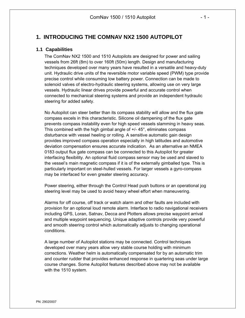
1.1 CapabilitiesThe ComNav NX2 1500 and 1510 Autopilots are designed for power and sailingvessels from 26ft (8m) to over 160ft (50m) length. Design and manufacturingtechniques developed over many years have resulted in a versatile and heavy-dutyunit. Hydraulic drive units of the reversible motor variable speed (PWM) type provideprecise control while consuming low battery power. Connection can be made tosolenoid valves of electro-hydraulic steering systems, allowing use on very largevessels. Hydraulic linear drives provide powerful and accurate control whenconnected to mechanical steering systems and provide an independent hydraulicsteering for added safety.
No Autopilot can steer better than its compass stability will allow and the flux gatecompass excels in this characteristic. Silicone oil dampening of the flux gateprevents compass instability even for high speed vessels slamming in heavy seas.This combined with the high gimbal angle of +/- 45°, eliminates compassdisturbance with vessel heeling or rolling. A sensitive automatic gain designprovides improved compass operation especially in high latitudes and automotivedeviation compensation ensures accurate indication. As an alternative an NMEA0183 output flux gate compass can be connected to this Autopilot for greaterinterfacing flexibility. An optional fluid compass sensor may be used and slaved tothe vessel’s main magnetic compass if it is of the externally gimballed type. This isparticularly important on steel-hulled vessels. For larger vessels a gyro-compassmay be interfaced for even greater steering accuracy.
Power steering, either through the Control Head push buttons or an operational jogsteering level may be used to avoid heavy wheel effort when maneuvering.
Alarms for off course, off track or watch alarm and other faults are included withprovision for an optional loud remote alarm. Interface to radio navigational receiversincluding GPS, Loran, Satnav, Decca and Plotters allows precise waypoint arrivaland multiple waypoint sequencing. Unique adaptive controls provide very powerfuland smooth steering control which automatically adjusts to changing operationalconditions.
A large number of Autopilot stations may be connected. Control techniquesdeveloped over many years allow very stable course holding with minimumcorrections. Weather helm is automatically compensated for by an automatic trimand counter rudder that provides enhanced response in quartering seas under largecourse changes. Some Autopilot features described above may not be availablewith the 1510 system.

ComNav 1500 / 1510 Autopilot - 2 -
PN: 29020007
1.2 Principle of OperationThe powerful microprocessor in the Distribution Unit accepts heading informationfrom magnetic or gyro compasses and radio navigation receivers and compares thisagainst the course set by the Control Head and rudder information as sent by theRudder Transmitter. Any difference between the set and actual course is comparedalong with the rate of change and trends in change (PID control), to drive thePumpset motor or solenoid directional valve, moving the rudder as necessary toreturn the vessel back to course. The sensitivity to course errors and amount ofcorrection are user adjustable to suit different vessels under changing seaconditions. Factory default settings establish a basis for normal steering and may befurther optimized as necessary. During set up procedures, the compass isautomatically compensated and installation errors such as reversed rudder feedbackand reversed Pumpset wiring or piping are automatically diagnosed and corrected.During this procedure the rudder speed is automatically optimized. This greatlyreduces installation calibration and sea trials time while eliminating possibleAutopilot malfunction.

ComNav 1500 / 1510 Autopilot - 3 -
PN: 29020007
1.3 Components
1.3.1 Autopilot Instrument Control HeadThe control and display of all Autopilot functions are providedby the Control Head. It is waterproof and may be mountedbelow or above deck. Multiple Control Heads are connectedin parallel (daisy chain) and any station may be activated bypressing any one of its keys. A portable Control Head is alsoavailable for remote control (not shown).
PN 20620044
1.3.2 45 ° Flux Gate CompassThe flux gate compass provides a stable heading referencefor the Autopilot and course repeater function on the ControlHead. It is gimbaled to accept up to +/- 45 ° of pitch and rolland should be bulkhead mounted below decks near thecenter of pitch and roll for maximum stability. Construction issplashproof. The Autopilot may also be used to transmitNMEA heading data to additional receivers such as radars,plotters, compass repeaters etc.
PN 20640006
1.3.3 35 ° Flux Gate CompassThe flux gate compass is low weight, fluid damped andcompact in size allowing for mounting in cramped areas. Itcan be flush mounted and is auto-deviated from the AutopilotInstrument Control Head.
PN 20640007
1.3.4 Distribution UnitThe Distribution Unit contains the course computer and motordrive circuitry and acts as a central distribution forinterconnecting wiring. This unit accepts data from thecompass, Control Heads, radio navigational receivers andRudder Transmitter. The DU-1500 is waterproof and may bemounted in any convenient and cool area. The DU-1510 issplashproof and should be mounted in a water protected coolarea. (shown) DU-1500 PN 20090002
DU-1510 PN 20100002
1.3.5 Rudder Follower & LinkageThe Rudder Follower & Linkage provides the Autopilot withaccurate rudder position information. It is mounted near therudder shaft and connected to the tiller or quadrant with a balljoint linkage. PN 20330008+20330007
OFF
N 2AUTOPILOT
SET
MODE

ComNav 1500 / 1510 Autopilot - 4 -
PN: 29020007
1.3.6 Reversing PumpsetsVarious sizes and types of Pumpsets are available whichconnect into the vessel’s hydraulic steering system,pumping oil on command from the Distribution Unit so asto drive the steering cylinder to the required rudder angle.The reversing motor Pumpset is only operation whencarrying out a rudder command. When the vessel is oncourse the motor stops. A variable speed motor driveadjusts maximum rudder positioning accuracy. Optionalsolenoid valve controlled Pumpsets are available for useon larger vessels. Construction is splashproof.
1.3.7 Linear DriveA hydraulic cylinder is provided for driving the quadrant ofmechanical steering systems. The cylinder is driven byone of the above Pumpsets and includes a small hydraulicreservoir and bypass valve that frees the hydraulic systemwhen the Autopilot is not in use. This linear drive providesa cleaner installation (being entirely below deck) anddelivers much more torque to the rudder than wheel drivenunits. In case the mechanical steering should fail, thecylinder provides a back up hydraulic steering.
1.3.8 Solenoid Valve DriveOn larger vessels the main hydraulic steering may be fittedwith a Solenoid Valve controlled power steering. In thiscase the Autopilot does not need to be supplied with aPumpset drive unit since the Distribution Unit output canbe reconfigured with its board mounted DIP selector switchto provide drive for steering solenoids having coil voltagesof 12 or 24 VDC.

ComNav 1500 / 1510 Autopilot - 5 -
PN: 29020007
1.4 Accessories
1.4.1 NX2 Autopilot Instrument Control HeadAdditional Autopilot Instruments Control Head (PN 20620044) may be added. Theyare connected in a "daisy chain" fashion from one to the other, matching colors onterminals. Control may be transferred from one instrument to another by simplypressing any pushbuttons (except the OFF push-button) on the instrument whereactive control is desired. All other inactive instruments will display the sameinformation as the active instrument, however in the lower display the text "passive"will blink once every seven seconds.
1.4.2 NX2 Remote Control InstrumentThe Remote Control Instrument (PN 20620048) is an instrument in itself that canbe set in either Autopilot mode to be used as an Autopilot instrument, or Instrumentmode displaying all information on the NX2 Network. The Network Remote ControlInstrument (PN 85006) can be used as a remote control for all instrumentsconnected to the Network. It is the ultimate NX2 instrument!
1.4.3 NX2 Analog Rudder Angle Indicator Instrument (RAI)The Analog Rudder Angle Indicator Instrument (PN 20620037) indicates the rudderangle (50°- - 0° -- 50°). This instrument is connected on the NX2 data bus cable asper color codes.
1.4.4 NX2 Multi Control Instrument with ServerThe NX2 Server is the heart of the NX2 Network to which transducers for speed,depth, wind, compass and navigators are connected. The Multi Control is a multi-function instrument that displays a main and a sub-function, grouped into 4 pagesfor speed, depth navigation and wind information. The Multi Control instrument andthe Server are the building components of the NX2 Network.
1.4.5 External Alarm BuzzerAn external alarm buzzer (PN 30620023) can be connected to the Server only.When activated, provides a local alarm at the Control Head in case the Autopilotfalls off course, develops a fault or the helmsman should fall asleep. The buzzercan be positioned where it may be heard such as in the Captain's cabin, when anyalarm is activated.
1.4.6 NFU Jog LeverA Non Follow Up (NFU) jog lever (PN 20310002) may be connected through theAutopilot to directly control the steering Pumpset in any mode except standbymode. This is useful for docking or remote maneuvering such as required whenpicking up crab traps etc. In any automatic pilot mode, the jog steering can be usedas a dodge function and when the jog lever is let go, the boat will revert to theprevious pilot course setting.

ComNav 1500 / 1510 Autopilot - 6 -
PN: 29020007
2. INSTALLATION
2.1 General CommentsMore than any other piece of marine electronics, reliable and accurate operation ofan Autopilot depends on correct installation. Please read and be sure you fullyunderstand the installation requirements before attempting installation.
The installation includes 6 major steps:1. Read the installation and operation manual completely.2. Plan where to install the equipment.3. Run the cables.4. Install the transducers and instruments.3. Make the attachments needed for Pumpset and cylinder and install them.6. Learn the functions and calibrate your system.
Before you begin drilling ... think about how you can make the installation as neatand simple as your boat will allow. Plan where to position the transducers, Serverand instruments. Think about leaving space for additional instruments in the future.
A few ”do nots” you should consider:• Do not cut the cables too short. Allow extra cable length at the Distribution
Box (Servo Unit) so it can be disconnected for inspection without having todisconnect all attached cables.
• Do not place sealant behind the display. The instrument gasket eliminatesthe need for sealant.
• Do not run cables in the bilge, where water can appear.• Do not run cables close to fluorescent light sources, engine or radio
transmitting equipment to avoid electrical disturbances.• Do not rush; take your time. A neat installation is easy to do.
The following tools and materials will be needed:• Wire cutters and strippers.• Small and large Philips and small flat head screw driver.• Hole saws: 63mm OD (2½") and 89mm OD (3 ½”).• Drill bit for 5mm OD (1/4").• Plastic cable ties
If you are doubtful about the installation, obtain the services of an experiencedtechnician.

ComNav 1500 / 1510 Autopilot - 7 -
PN: 29020007
2.2 Distribution Unit 1500 & 1510LocationThe Distribution Unit must be mounted on a dry, flat and vertical surface belowdeck, at least 500 mm (20") from radio receiving equipment. Since all wiringoriginates at the Distribution Unit, it should be centrally located to minimize lengthsof wiring. It is most important to minimize the runs of power and motor leads sincevoltage drop in these cables will reduce steering capacity.
InstallationNote: The 1500 and 1510 Autopilots are designed for different applications:The 1500 is designed as a Stand Alone System.The 1510 is designed to work as part of a Network System, by connecting it to theNX2 Network.
Place the adhesive drill template provided in the desired location for the appropriateDistribution Unit and drill accordingly. (Reference the following pages). Remove thetemplate. To mount the Distribution Unit, remove the cover screws. The 4 innermounting holes are now exposed. Mount the Distribution Unit with 4 screws (notsupplied).
Note for the 1500 Distribution Box: If any waterproof cable glands do not havecables inserted, install the short rubber plug provided in order to maintain watertightness. If many options are connected and not enough glands are available, usea separate junction box and route the excess wires through one large cable in oneof the large glands.
Note for the Autopilot Instrument / NX2 Network connection. If you want to runthe NX2 Network instruments separate from the Autopilot, do not connect greenwire to (pin 1) to the left in Distribution Unit. Instead insulate the green wire.
Wire thickness - Important! Use the following table to determine wire thickness.Total distance from battery to Distribution Unit and distance from Distribution Unit toPumpset must be used to determine the wire thickness from the table.
Cable Length Maximum(m) (ft)
Wire Size(mm2)
Wire Size(AWG)
3 10 2.5 145 16 4 12
7.5 25 6 1012 40 8 8
Make sure, that the wire size between the battery and the point where you will connectthe wire to the Distribution Unit is big enough to secure power supply to all otherconnected electrical units on board. If you are in doubt, ask your local technician.
ComNav 1500 / 1510 Autopilot - 8 -
PN: 29020007
0.20" DIA. , 4 OFFFOR #8 TAPPING SCREW
5.56"
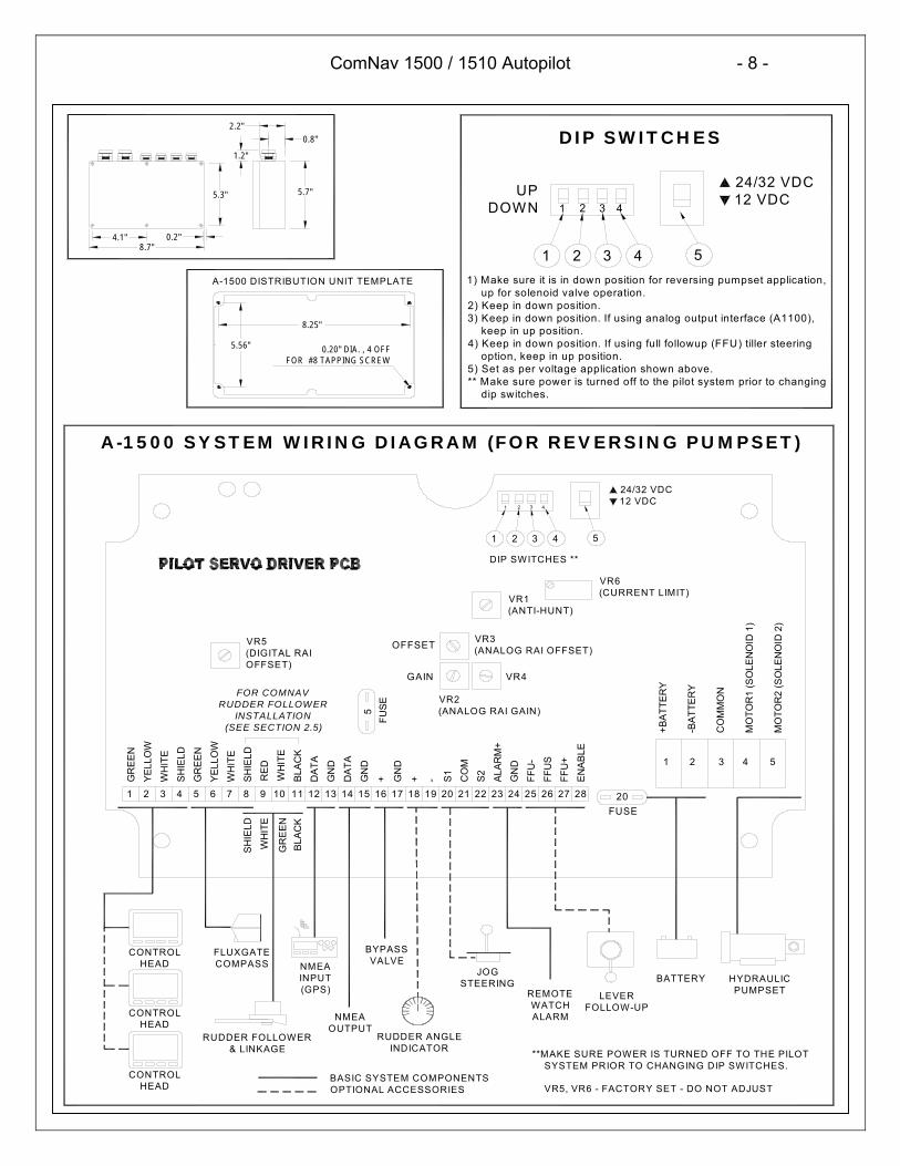
1) Make sure it is in down position for reversing pumpset application, up for solenoid valve operation.2) Keep in down position.3) Keep in down position. If using analog output interface (A1100), keep in up position.4) Keep in down position. If using full followup (FFU) tiller steering option, keep in up position.5) Set as per voltage application shown above.** Make sure power is turned off to the pilot system prior to changing dip switches.
2028272625242322212019181716151413121110987654321
CONTROLHEAD
CONTROLHEAD
CONTROLHEAD
REMOTEWATCHALARMNMEA
OUTPUTRUDDER FOLLOWER
& LINKAGE
BASIC SYSTEM COMPONENTSOPTIONAL ACCESSORIES
**MAKE SURE POWER IS TURNED OFF TO THE PILOT SYSTEM PRIOR TO CHANGING DIP SWITCHES.
VR5, VR6 - FACTORY SET - DO NOT ADJUST
RUDDER ANGLEINDICATOR
RE
D
WH
ITE
BLA
CK
HYDRAULICPUMPSET
BATTERY
LEVER FOLLOW-UP
JOG STEERING
BYPASSVALVENMEA
INPUT(GPS)
FLUXGATECOMPASS
FUSE
A-1500 SYSTEM WIRING DIAGRAM (FOR REVERSING PUMPSET)
GR
EE
N
SH
IELD
WH
ITE
YE
LLO
W
GR
EE
N
FOR COMNAVRUDDER FOLLOWER
INSTALLATION (SEE SECTION 2.5)
WH
ITE
GR
EE
NB
LAC
K
VR4
VR2(ANALOG RAI GAIN)
VR3(ANALOG RAI OFFSET)
VR1(ANTI-HUNT)
VR6(CURRENT LIMIT)
VR5(DIGITAL RAIOFFSET)
GAIN
OFFSET
5FU
SE
MO
TOR
2 ( S
OLE
NO
ID 2
)5
MO
TOR
1 (S
OLE
NO
ID 1
)4
CO
MM
ON
3
-BA
TTE
RY
2
+BA
T TE
RY
1
EN
AB
LE
FFU
+
FFU
S
F FU
-
GN
D
ALA
RM
+
S2CO
M
S1-+GN
D
+GN
D
DA
TA
GN
D
DA
T A
SH
IELD
WH
ITE
YE
LLO
W
24/32 VDC12 VDC
5
DIP SWITCHES **
3 421
4321
0.2"8.7"
4.1"
1.2"
0.8"
A-1500 DISTRIBUTION UNIT TEMPLATE
8.25"
2.2"
5.7"5.3" UPDOWN
DIP SWITCHES
1 2 3 4
1 2 43 5
24/32 VDC12 VDC
SH
IELD

ComNav 1500 / 1510 Autopilot - 9 -
PN: 29020007
Ø0.10", 4 OFFFOR #6 TAPPING
SCREW2.6"
1) Make sure it is in down position for reversing pumpset application, up for solenoid valve operation.2) Keep in down position.3) Set as per voltage application shown above. Switch should be set to 12 for 12 VDC application or set to 24 for 24 VDC application.
** Make sure power is turned off to the pilot system prior to changing dip switches.
A-1510 SYSTEM WIRING DIAGRAM (FOR REVERSING PUMPSET)
-BAT
TERY
COM
MO
N
VR2
BASIC SYSTEM COMPONENTSOPTIONAL ACCESSORIES
**MAKE SURE POWER IS TURNED OFF TO THE PILOT SYSTEM PRIOR TO CHANGING DIP SWITCHES.
VR6 - FACTORY SET - DO NOT ADJUST
BYPASSVALVE
JOG STEERING
RUDDER ANGLEINDICATOR
22 S2
1
+BAT
TERY
23
16 +17 GND18 +19 -20 S121 COM
RUDDER FOLLOWER & LINKAGE
CONTROLHEAD
CONTROLHEAD
FLUXGATECOMPASS
NMEAINPUT(GPS)
BATTERY HYDRAULICPUMPSET
CONTROLHEAD
NMEA OUTPUT
1 2
BLACK BLACKGREENWHITERED
WHITEVR4 VR1
24 12
(SO
LENO
ID 2
)
(SO
LENO
ID 1
)
15 AMP FUSE
VR6
1 2
DIP SWITCHES **
3
5
MO
TOR2
7
WHITE
8
SHIELD
910
1112DATA 13GND 14DATA 15GND
4
MO
TOR1
FOR COMNAVRUDDER FOLLOWER
INSTALLATION (SEE SECTION 2.5)
VR3
5 AMP FUSE
1
GREEN
2
YELLOW
3
WHITE
4
SHIELD
5
GREEN
6
YELLOW
1.3"0.3"
1.2"
6.5"
2.2"4.3"
4.75"
3
21
24 12
DIP SWITCHES
21
A-1510 DISTRIBUTION UNIT TEMPLATE
UPDOWN
SHIELD
ComNav 1500 / 1510 Autopilot - 10 -
PN: 29020007
2.2.1 Distribution Unit ConnectionsDistribution Unit connections should be according to the System Wiring Diagramprovided and in addition, the following points:
2.2.2 Safety SwitchImportant! An external safety switch or circuit breaker (not supplied) should beinstalled in line with power input. Make sure it is rated greater than or equal to 25Amps.This switch will serve as your Autopilot ultimate safety OFF switch.
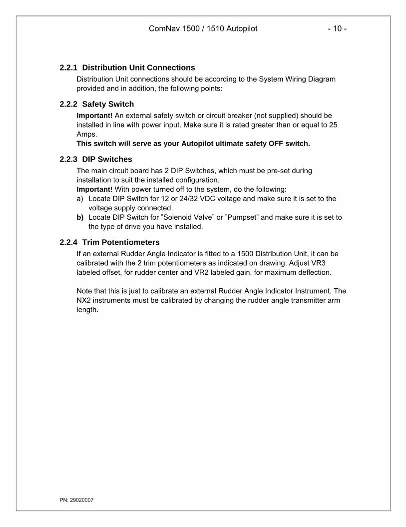
2.2.3 DIP SwitchesThe main circuit board has 2 DIP Switches, which must be pre-set duringinstallation to suit the installed configuration.Important! With power turned off to the system, do the following:a) Locate DIP Switch for 12 or 24/32 VDC voltage and make sure it is set to the
voltage supply connected.b) Locate DIP Switch for ”Solenoid Valve” or ”Pumpset” and make sure it is set to
the type of drive you have installed.
2.2.4 Trim PotentiometersIf an external Rudder Angle Indicator is fitted to a 1500 Distribution Unit, it can becalibrated with the 2 trim potentiometers as indicated on drawing. Adjust VR3labeled offset, for rudder center and VR2 labeled gain, for maximum deflection.
Note that this is just to calibrate an external Rudder Angle Indicator Instrument. TheNX2 instruments must be calibrated by changing the rudder angle transmitter armlength.
ComNav 1500 / 1510 Autopilot - 11 -
PN: 29020007
GROUND SYMBOL
SILICONE GREASE
2.3 Control Head
LocationThe Control Head is waterproof when gasket mounted to a flat surface. It should bemounted near the steering position for ease of visibility and transfer from manual toautomatic.
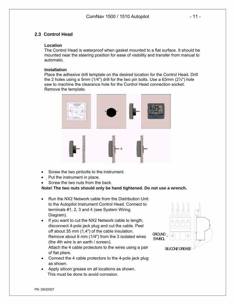
InstallationPlace the adhesive drill template on the desired location for the Control Head. Drillthe 2 holes using a 5mm (1/4") drill for the two pin bolts. Use a 63mm (2½") holesaw to machine the clearance hole for the Control Head connection socket.Remove the template.
• Screw the two pinbolts to the instrument.• Put the instrument in place.• Screw the two nuts from the back.Note! The two nuts should only be hand tightened. Do not use a wrench.
• Run the NX2 Network cable from the Distribution Unitto the Autopilot Instrument Control Head. Connect toterminals #1, 2, 3 and 4 (see System WiringDiagram).
• If you want to cut the NX2 Network cable to length,disconnect 4-pole jack plug and cut the cable. Peeloff about 35 mm (1,4") of the cable insulation.Remove about 6 mm (1/4") from the 3 isolated wires(the 4th wire is an earth / screen).Attach the 4 cable protectors to the wires using a pairof flat pliers.
• Connect the 4 cable protectors to the 4-pole jack plugas shown.
• Apply silicon grease on all locations as shown.This must be done to avoid corrosion.

ComNav 1500 / 1510 Autopilot - 12 -
PN: 29020007
• Apply silicon paste to the instrument connection pins at the back of theInstrument. Press the jack plug onto the instrument pins. Press the cable in to thecable leads.
• Secure the back cover with the screw.
All NX2 instruments are connected directly to the NX2 Network in a daisy chain.They all use the same colour coded 4-pole jack plugs.

ComNav 1500 / 1510 Autopilot - 13 -
PN: 29020007
2.4 Flux Gate CompassLocationCompass location is most critical. This compass operates with an automaticdeviation feature. Best performance will be obtained if mounted at the center ofpitch and roll, in order to minimize undesirable accelerate which can degradecompass stability. On most vessels this would be about 1/3 forward, on thecenterline and approximately at sea level. Various obstructions or magneticinterference may exist at this ideal location and a reasonable compromise isacceptable in establishing the exact location. The fore-aft arrow on the compassshould face forward and parallel to the boat centerline. If this is not possible, thecompass error resulting (lubber line error) may be corrected after Autodeviation hasbeen performed. The compass should be mounted with the cable outlet at thebottom (See diagram on following page).
The following safe magnetic distances should be maintained where possible:
OBJECT SAFE DISTANCEFt. m.
Main Engine 7 2Radar Magnetrons 5 1.5Horizontal and Vertical Steel Plates, Tanks 3 1High Power Electric Motors (bilge pumps,refrigerators)
3 1
HF or VHF Antennas 10 3High Current DC wires 3 1Magnetic meter movements and loud speakers 3 1Large bolts or fasteners 2 0.6
The above may not always be possible to maintain due to problems unique to eachvessel. If in doubt, check for local magnetic disturbance using the Installationprocedure.
Steel vessels are a special case and an experienced compass adjuster should beconsulted since the automatic compass compensation only corrects for horizontalerrors and significant deviation from vertical fields such as Vertical Heeling Errorcan occur.
ComNav 1500 / 1510 Autopilot - 14 -
PN: 29020007
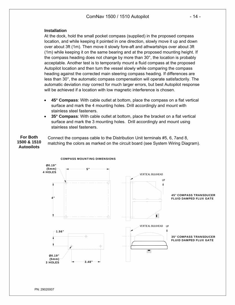
InstallationAt the dock, hold the small pocket compass (supplied) in the proposed compasslocation, and while keeping it pointed in one direction, slowly move it up and downover about 3ft (1m). Then move it slowly fore-aft and athwartships over about 3ft(1m) while keeping it on the same bearing and at the proposed mounting height. Ifthe compass heading does not change by more than 30°, the location is probablyacceptable. Another test is to temporarily mount a fluid compass at the proposedAutopilot location and then turn the vessel slowly while comparing the compassheading against the corrected main steering compass heading. If differences areless than 30°, the automatic compass compensation will operate satisfactorily. Theautomatic deviation may correct for much larger errors, but best Autopilot responsewill be achieved if a location with low magnetic interference is chosen.
• 45° Compass: With cable outlet at bottom, place the compass on a flat verticalsurface and mark the 4 mounting holes. Drill accordingly and mount withstainless steel fasteners.
• 35° Compass: With cable outlet at bottom, place the bracket on a flat verticalsurface and mark the 3 mounting holes. Drill accordingly and mount usingstainless steel fasteners.
Connect the compass cable to the Distribution Unit terminals #5, 6, 7and 8,matching the colors as marked on the circuit board (see System Wiring Diagram).
VERTICAL BULKHEAD
UP
45° COMPASS TRANSDUCERFLUID DAMPED FLUX GATE
VERTICAL BULKHEAD
COMPASS MOUNTING DIMENSIONS
5"
4"
Ø0.19"(5mm)
4 HOLES
3.48"
1.56"
Ø0.19"(5mm)
3 HOLES
35° COMPASS TRANSDUCERFLUID DAMPED FLUX GATE
UP
For Both1500 & 1510Autopilots
ComNav 1500 / 1510 Autopilot - 15 -
PN: 29020007
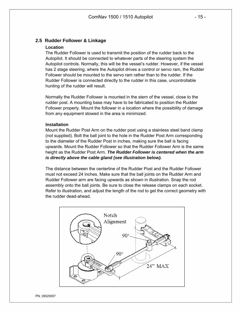
2.5 Rudder Follower & LinkageLocationThe Rudder Follower is used to transmit the position of the rudder back to theAutopilot. It should be connected to whatever parts of the steering system theAutopilot controls. Normally, this will be the vessel’s rudder. However, if the vesselhas 2 stage steering, where the Autopilot drives a control or servo ram, the RudderFollower should be mounted to the servo ram rather than to the rudder. If theRudder Follower is connected directly to the rudder in this case, uncontrollablehunting of the rudder will result.
Normally the Rudder Follower is mounted in the stern of the vessel, close to therudder post. A mounting base may have to be fabricated to position the RudderFollower properly. Mount the follower in a location where the possibility of damagefrom any equipment stowed in the area is minimized.
InstallationMount the Rudder Post Arm on the rudder post using a stainless steel band clamp(not supplied). Bolt the ball joint to the hole in the Rudder Post Arm correspondingto the diameter of the Rudder Post in inches, making sure the ball is facingupwards. Mount the Rudder Follower so that the Rudder Follower Arm is the sameheight as the Rudder Post Arm. The Rudder Follower is centered when the armis directly above the cable gland (see illustration below).
The distance between the centerline of the Rudder Post and the Rudder Followermust not exceed 24 inches. Make sure that the ball joints on the Rudder Arm andRudder Follower arm are facing upwards as shown in illustration. Snap the rodassembly onto the ball joints. Be sure to close the release clamps on each socket.Refer to illustration, and adjust the length of the rod to get the correct geometry withthe rudder dead-ahead.
ComNav 1500 / 1510 Autopilot - 16 -
PN: 29020007
If the locking screw in the Rudder Follower arm has been loosened, or the armremoved from the Rudder Follower, re-attach the arm and check the potentiometercenter position. When the rudder is dead-ahead, the electrical resistance betweenthe black and green wires and the white and green wires should be equal (approx.600 ohms each).
Be careful to check the installation for any mechanical obstructions or binding of thelinkage, and correct it now, before it becomes a problem.
The Rudder Follower is supplied with approximately 15.5m (50’) of cable. Run thecable from the Rudder Follower towards the SPU, ensuring that a hose or conduitprotects it wherever it passes through fish or cargo holds, or any other area whereit could be damaged.
If the length of cable supplied is too short to reach all the way to the SPU, obtain aterminal strip and sufficient additional cable from your dealer. Mount the terminalstrip in a convenient DRY location.
Connect cable to Distribution Unit terminals #8, 9, 10 and 11. Rudder FollowerWires: shield to terminal #8 (Flux Gate shield), white to terminal #9 (marked red),green to terminal #10 (marked white) and black to terminal #11 (marked black).
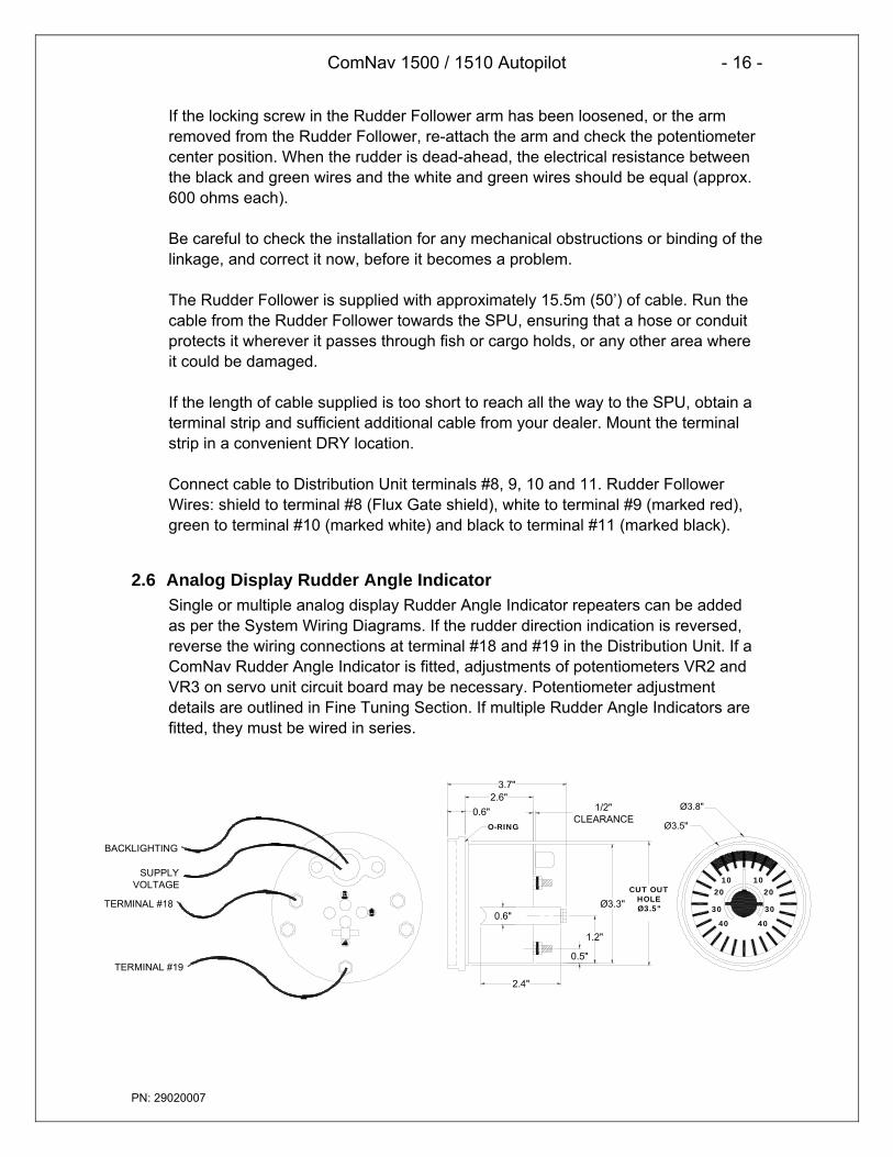
2.6 Analog Display Rudder Angle IndicatorSingle or multiple analog display Rudder Angle Indicator repeaters can be addedas per the System Wiring Diagrams. If the rudder direction indication is reversed,reverse the wiring connections at terminal #18 and #19 in the Distribution Unit. If aComNav Rudder Angle Indicator is fitted, adjustments of potentiometers VR2 andVR3 on servo unit circuit board may be necessary. Potentiometer adjustmentdetails are outlined in Fine Tuning Section. If multiple Rudder Angle Indicators arefitted, they must be wired in series.
1020
30
40 40
30
2010
BACKLIGHTING
TERMINAL #18
TERMINAL #19
SUPPLY VOLTAGE
3.7"
0.6"2.6"
0.6"
2.4"
CUT OUTHOLEØ3.5"
Ø3.3"
1.2"
0.5"
O-RING
1/2"CLEARANCE
Ø3.5"
Ø3.8"

ComNav 1500 / 1510 Autopilot - 17 -
PN: 29020007
2.7 NMEA 0183 Compass InterfaceFor the 1500 Distribution Unit: Use the NMEA 0183 Compass Interface availablefrom ComNav. Wiring interconnection instructions are provided with the NMEA0183 Compass Interface. Calibration parameter “CAL c6” can be used to adjust forheading offsets.
For the 1510 Distribution Unit: the NMEA 0183 Output Compass can beconnected directly to terminals #14 and #15.
2.8 LFU101 Full Follow Up (FFU) Tiller SteeringIf you do not have a Full Follow Up (Tiller) lever, go to next item. The FFU steeringcontrol lever or knob can be used to maneuver the vessel. The FFU steering willcontrol the rudder to the angle commanded by the follow up control lever or knob.The DIP Switch on the servo until circuit board must be set up correctly to use thisfunction. The use operation and instruction manual for the FFU steering lever orknob control is provided with the unit. The FFU steering feature is not available withthe A-1510 Distribution Unit.
InstallationThe jog switch should be wired at terminals #20, 21 and 22 in the Distribution Unit.If using a ComNav Jog Lever, the white wire from the Jog Lever should beconnected to terminal #20 of the Distribution unit. The green (common) wire of theJog Lever should be connected to terminal #21, and the black wire should beconnected to terminal #22. Additional jog levers may be added to the system byelectrically wiring them in parallel to terminals #20, #21 and #22 of the DistributionUnit.
2.9 Reversing PumpsetsPumpsets should be connected into the vessel’s hydraulic steering systemaccording to piping schematics shown on the following pages. Most multiple stationsteering systems have lock valves, which automatically isolate stations from eachother and from the Autopilot Pumpset. Where a lock valve is not fitted, it should beobtained from ComNav and installed to isolate the helm. The Pumpset issplashproof and should be mounted in a cool dry location, which minimizeshydraulic piping and wiring runs.
Reference the following 3 pages for various hydraulic steering systemscomplete with required fittings.

ComNav 1500 / 1510 Autopilot - 18 -
PN: 29020007
Helm Pump
Filler vent plug
Pumpset
Tiller
Rudder
Steering Cylinder
TEE FITTING MUST BE INSTALLED POINTING UPWARDS AS SHOWN.
RESERVOIR PORTGRADUAL RISE
OPTION PF0.3 PUMPSET
GRADUAL RISE
RESERVOIR PORT
TEE FITTING MUST BE INSTALLED POINTING UPWARDS AS SHOWN.
Helm Pump
Pumpset
Tiller
Rudder
Steering Cylinder
OPTION PV1.4 PUMPSET
ComNav PV Series Pumpset with Teleflex 250V & 275V systems. Mount Teleflex Uniflow Valve at least 6' (2m) from helm pump.
Filler vent plug

ComNav 1500 / 1510 Autopilot - 19 -
PN: 29020007
OPTION PV1.4 PUMPSETOPTION PF0.3 PUMPSET
ComNav PV Series Pumpset with Hynautic pressurized Reservoir systems. 1B 251, 1B 511, 1B 231, 1B 531.
Helm Pump
Rudder
TELEFLEX UNIFLOW VALVE
Tiller
Pumpset
Steering Cylinder
RESERVOIR PORT
WITH GRADUAL RISE
TELEFLEX HV4151 VALVE
RESERVOIR PORT
Tiller
Pumpset
Steering Cylinder
Rudder
Helm Pump
Filler vent plug
Filler vent plug

ComNav 1500 / 1510 Autopilot - 20 -
PN: 29020007
2.10 Installing FittingsIt is recommended that all fittings be installed and aligned in the Pumpset before itis mounted. The type of fitting required i.e., straight or 90° will depend on themounting position of the pump and the location of piping. Refer to “Mounting thePumpset” for permissible orientations. All ports on the Pumpset are ¼” NPT. Pipesealant or Teflon tape is required on all male pipe thread fittings. Be certain to keepthe sealant or tape at least two threads away from the starting threads to preventshredded tape or sealant from contaminating the system. The tube fittings selectedmust be suitable for the tubing size used. 3/8” OD (outside diameter) or equivalentis recommended.
2.11 Mounting the PumpsetThe Pumpset may be mounted horizontally (motor feet down) or vertically with thepump positioned above the motor. Be certain to leave adequate space to accessthe bleed fitting and flow-adjustment nut.Four #10 screws and washers are required to hold the Pumpset to the mountingsurface.
Tiller
RESERVOIR PORTPumpset
Rudder
Steering Cylinder
Helm Pump
OPTION PV1.4 PUMPSETOPTION PF0.3 PUMPSET
ComNav PV Series Pumpset with Hynautic pressurized Heavy Duty systems. M2 1150, MS 1175, MS 1200, MS 2175, MS 2200.
Filler vent plug

ComNav 1500 / 1510 Autopilot - 21 -
PN: 29020007
2.12 Piping the System3/8” OD copper tubing suitable for a working pressure of 1,000 psi or equivalent isrecommended for all connections. Flexible hose may be used but must have arated working pressure of 1,000 psi.
2.13 Filling the SystemOnce the main steering system has been filled, open the Pumpset bleed screw(labeled on top of Pumpset), two complete turns. Wait until clear oil, void of any air,exits the bleed fitting. Re-secure the bleed screw. Be certain that the flow adjustingwheel is set at the maximum flow position if applicable. Top up the uppermost helmpump or reservoir, if necessary. Once the cylinder responds instantly, most of theair has been removed and the system is usable. The remaining air trapped in thesystem will vent automatically with use. Refill the steering system reservoir asnecessary with oil as recommended by the steering manufacturer. Where norecommendation is available use hydraulic oil of viscosity grade ISO 32.
2.14 Linear DriveThe Linear Drive is only fitted on vessels with mechanical steering. The LinearDrive consists of a hydraulic cylinder, which is connected to the mechanicalsteering system to provide rudder steering drive for the Autopilot. A hydraulicPumpset is connected to the steering cylinder. The Pumpset motor is drivenclockwise or counter-clockwise by the Autopilot to produce port or starboardmovement of the rudder. When the Autopilot is turned off, a solenoid operatedbypass valve opens, permitting hydraulic oil to shuttle from one side of thehydraulic cylinder to the other, allowing the mechanical system to regain control.
PILOT DISTRIBUTION BOX
RESERVOIR
SOLENOIDBYPASS VALVE
STEERING CYLINDER
AUTOPILOT CONTROL HEAD
PUMPSET
ComNav 1500 / 1510 Autopilot - 22 -
PN: 29020007
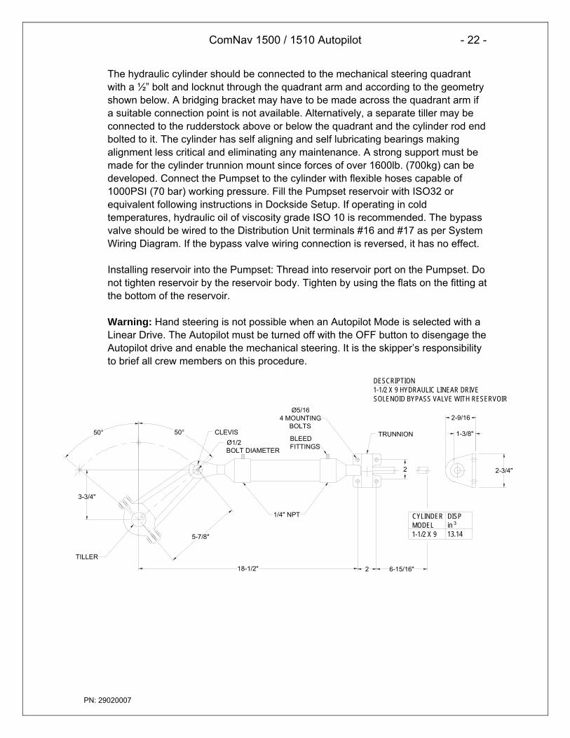
The hydraulic cylinder should be connected to the mechanical steering quadrantwith a ½” bolt and locknut through the quadrant arm and according to the geometryshown below. A bridging bracket may have to be made across the quadrant arm ifa suitable connection point is not available. Alternatively, a separate tiller may beconnected to the rudderstock above or below the quadrant and the cylinder rod endbolted to it. The cylinder has self aligning and self lubricating bearings makingalignment less critical and eliminating any maintenance. A strong support must bemade for the cylinder trunnion mount since forces of over 1600lb. (700kg) can bedeveloped. Connect the Pumpset to the cylinder with flexible hoses capable of1000PSI (70 bar) working pressure. Fill the Pumpset reservoir with ISO32 orequivalent following instructions in Dockside Setup. If operating in coldtemperatures, hydraulic oil of viscosity grade ISO 10 is recommended. The bypassvalve should be wired to the Distribution Unit terminals #16 and #17 as per SystemWiring Diagram. If the bypass valve wiring connection is reversed, it has no effect.
Installing reservoir into the Pumpset: Thread into reservoir port on the Pumpset. Donot tighten reservoir by the reservoir body. Tighten by using the flats on the fitting atthe bottom of the reservoir.
Warning: Hand steering is not possible when an Autopilot Mode is selected with aLinear Drive. The Autopilot must be turned off with the OFF button to disengage theAutopilot drive and enable the mechanical steering. It is the skipper’s responsibilityto brief all crew members on this procedure.
2 6-15/16"
2-3/4"
1-3/8"
2
5-7/8"
3-3/4"
18-1/2"
50°50° CLEVISBLEEDFITTINGS
TRUNNIONØ1/2 BOLT DIAMETER
1/4" NPT
TILLER
2-9/16Ø5/16
4 MOUNTING BOLTS
DESCRIPTION1-1/2 X 9 HYDRAULIC LINEAR DRIVESOLENOID BYPASS VALVE WITH RESERVOIR
CYLINDER MODEL1-1/2 X 9
DISPin13.14
3

ComNav 1500 / 1510 Autopilot - 23 -
PN: 29020007
2.15 Solenoid Valve Controlled PumpsetsIf the vessel is already fitted with a Solenoid Valve Controlled Pumpset having coilsfor 12 or 24 VDC, connect the solenoid coils directly to the Distribution Unit as perSystem Wiring Diagram provided. DIP Switch 1 is set in the “up” position (refer toSystem Wiring Diagram).
Solenoid Valve Controlled Pumpsets should be adjusted to speeds of 14 secondsfrom hardover port to hardover starboard or slower for maximum accuracy. Fasterhardover times will require increased anti-hunt settings to prevent hunting(overshoot of the rudder).
To adjust anti-hunt setting, first complete procedures in Dockside Setup and SeaTrails. Engage the Autopilot and with the Pumpset running, make 10 ° coursechanges to port and starboard. If the rudder hunts (i.e. oscillates rapidly back andforth during these course changes), gradually increase the anti-hunt control (i.e.very slowly adjust VR1 trim potentiometer counterclockwise) until the rudderremains stable. Do not increase the anti-hunt control any more than necessary asthis can begin to degrade course accuracy.
2.16 AccessoriesInstall any accessories as per instructions included with them and according towiring as shown in System Wiring Diagrams included in this manual.
When you finished the installation, perform the Dockside Testing routine.

ComNav 1500 / 1510 Autopilot - 24 -
PN: 29020007
3. ADVANCED OPERATION
3.1 Adjusting Response (See Calibration Menus).Note: the rudder [RUD] and counter rudder [CRD] settings are inter-related andmay effect the performance of each other. Setting by trial and error may berequired.
3.2 Rudder [RUD] FunctionThe most critical adjustment for good steering is the rudder. Too high a setting willcause excessive amounts of rudder to be given that force the vessel to hunt rapidlyback and forth across the course. Too low a setting lets the vessel slowly fall ofcourse with repeated corrections required to get back on course. The rudder shouldbe set to the position where positive control of course is achieved without undueactivity. Run the vessel at its cruising speed and make a course change with thekeypad of 40°. The vessel should not overshoot by more than 3° to 4°. Adjust therudder until this is achieved.
3.3 Sea State [SEA] FunctionThe parameter is a combination of yaw dead-band (compass sensitivity) andcompass damping. The minimum setting may only be used under calm seaconditions to avoid unnecessary rudder correction due to compass accelerationerrors. Smaller vessels and high-speed vessels, which are subject to moreacceleration in lighter seas, will have to use higher settings. Larger and more stablevessels can use lower settings since there is less compass disturbance. Thefactory default setting should work on most vessels in light to moderate seaconditions. Following seas, no matter how rough, require lower settings to catchcourse error trends quickly in order to minimize excessive yaw.
3.4 Counter Rudder [CRD] FunctionThis feature senses the rate of change of heading and gives additional ruddercorrections if the vessel is rapidly falling off course, and backs off the rudder as avessel approaches the desired heading. Its effect is to rapidly catch the tendency toyaw in a quartering sea, provide initially high rudder control when making a largecourse change and to decelerate the swing of the bow as vessel approaches thedesired course. When using this feature, course holding of heavy and difficult tosteer vessels is greatly improved. Insufficient counter rudder will allow the vessel toovershoot on large course changes and too much will cause unnecessary ruddercorrections and a tendency to stop short of coming to a new course, requiringseveral successive corrections before easing up to the new heading. To optimizecounter rudder, initially set it to minimum and adjust the rudder so that the vesselresponds smartly to a 40°-course change with less than 3° to 4 ° of overshoot.Then increment the counter rudder one step at a time while testing 40 °-coursechanges, until the vessel achieves an overshoot of 2° or less. Remember any airin the hydraulic system will prevent precision control.

ComNav 1500 / 1510 Autopilot - 25 -
PN: 29020007
3.5 Automatic Trim [ATC] FunctionAutomatic Trim Adjustment is not critical. It constantly compares the course setagainst the course steered. If a persistent error exists due to wind, waves orunbalanced forces (such as a single screw operation of a twin screw vessel), or anoff-center tow or weather helm on a sailing vessel, the automatic trim slowly appliesmore rudder as necessary to reduce the error to zero. If the trim time is set toohigh, it will take a long time to eliminate the course error. If it is set too low it canstart to degrade course stability. In general, longer trim times (higher settings)should be set for large vessels and sailing vessels and shorter trim times (lowersettings) for small vessels and high speed planning vessels. The factory defaultsetting should be acceptable for all but extreme applications.

ComNav 1500 / 1510 Autopilot - 26 -
PN: 29020007
4. AUTOPILOT INSTRUMENT CONTROL HEAD OPERATION
4.1 Instrument Overview
4.1.1 Instrument DisplayThe display consists of two lines, a top-line with 24mm (1”) digits and a lower-linewith 13mm (0.5”) digits.
4.1.2 Instrument Pages and FunctionsThe Autopilot instrument has its functions divided into 4 pages. The pagenames are printed above the display:
HEADING (Compass), NAV (Navigation), WIND and PWR ST (Power steer)The selected function is indicated by the page-arrow at top of the display.
4.1.3 Instrument Modes Standby Mode: The instrument functions as a passive compass repeater. Autopilot Mode: When any Autopilot function is activated. Setup Mode: Allows calibrating your Network settings. Edit Mode: Allows editing settings (when digits are flashing).
4.1.4 Power On/OffYou will switch on/off your NX2 instruments by using the instrumentswitch on your electrical panel as the instruments have no separatepower on/off-button.
Top-Line HeadingPage Arrow
ReferenceCourse/Angle Function
AUTO Mode On
Lower-LineFunction Text
OFFLEFT MODE RIGHT SET

ComNav 1500 / 1510 Autopilot - 27 -
PN: 29020007
4.2 How to Use the Push-Buttons
4.2.1 MODEA press on MODE, moves one page to the right, indicatedby the page-arrow at top of the display.In edit mode, a press on MODE moves the cursor one stepto the right. If the cursor is at the farthest right hand side,a further press will cause it to rotate back to the left hand side.
4.2.2 LEFTWhen the Autopilot is activated, a short press on LEFTdecreases the course by 1°, a long press decreasesthe course by 10°.In setup mode a press on LEFT moves to the previous setupfunction. In edit mode a press on LEFT decreases a digitby one.
4.2.3 RIGHTWhen the Autopilot is activated, a short press on RIGHTIncreases the course by 1°, a long press increasesthe course by 10°. In setup mode a press on RIGHTmoves to the next setup function. In edit mode a press onRIGHT increases a digit by one.
4.2.4 SETA press on SET engages the Autopilot in the selected steeringfunction (HDG, NAV WIND, or PWR ST).In Setup Mode, a press on SET unlocks a digit to access editmode. When unlocked, the digits are ”active” (flashes) and canbe edited by pressing LEFT, RIGHT and MODE as required.When finished editing, lock the digit by another press on SET.
4.2.5 OFFA press on OFF turns the Autopilot.
4.2.6 TackA press on LEFT and RIGHT together, performs a Tackwhen steering in wind mode. &

ComNav 1500 / 1510 Autopilot - 28 -
PN: 29020007
4.2.7 Setup ModeTo access Setup Mode, press and hold MODE more than2 seconds. [Lit OFF] flashes. To move to next setup group,press MODE again.
To return to standby mode, press SET when the text return 2 seconds[RET] is displayed.
4.2.8 LightingThe instrument uses red back lighting for the display and the 4push-buttons. The light can be set at 4 different levels.To access the light control, press and hold MODE for morethan 2 seconds. The flashing text [Lit OFF] will be displayedand the display will be lit momentarily.
To select between the 4 light levels [LOW], [MID], [MAX] and[OFF], press RIGHT. To lock the selected level, press SET.
If the Autopilot is connected to an NX2 network, the selectedlight level will be copied on to the Network. It is not possibleto reduce or turn off the lighting on an individual instrument.

ComNav 1500 / 1510 Autopilot - 29 -
PN: 29020007
5. FUNCTION
5.1 Standby ModeAt power On, the Autopilot starts in standby mode andoperates as a passive compass repeater. No page-arrowis shown at the top of the display.The current course is displayed on the top-line.The rudder angle is displayed on the bottom line.In any function, the top-line displays the heading at all times.
5.2 Autopilot ModePrior to activating any automatic steering function, the boatshould be steadied on the desired heading and on track for5 to 10 seconds to minimize large course changes whenactivated. The Autopilot operates with course errors up to 90°,and cross-track errors up to 2 nautical miles.
5.2.1 Activate Automatic SteeringTo select a steering function, press MODE.The page-arrow at top of the display indicates the selected page.To activate the selected steering function, press SET when thelower-line text is flashing.The reversed lit text [AUTO] to the right and in the middle on thedisplay always confirms that an automatic steering function isactivated. The function text at lower-line to the right confirms whichsteering function is activated, ex [HDG] for compass steering.
Note! If a page is not available, such as when no waypointinformation is programmed / activated or no navigator or windtransducer connected, the page-arrow will not stop at that page.
5.2.2 Turn Off Automatic SteeringTo turn off automatic steering, press OFF.To turn off the Autopilot when you are in the process of changingfunctions or are in setup mode, press and hold OFF for more thantwo seconds.
ComNav 1500 / 1510 Autopilot - 30 -
PN: 29020007
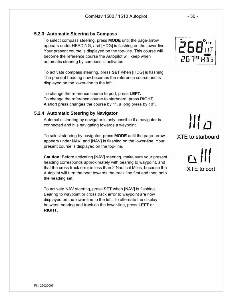
5.2.3 Automatic Steering by CompassTo select compass steering, press MODE until the page-arrowappears under HEADING, and [HDG] is flashing on the lower-line.Your present course is displayed on the top-line. This course willbecome the reference course the Autopilot will keep whenautomatic steering by compass is activated.
To activate compass steering, press SET when [HDG] is flashing.The present heading now becomes the reference course and isdisplayed on the lower-line to the left.
To change the reference course to port, press LEFT.To change the reference course to starboard, press RIGHT.A short press changes the course by 1°, a long press by 10°.
5.2.4 Automatic Steering by NavigatorAutomatic steering by navigator is only possible if a navigator isconnected and it is navigating towards a waypoint.
To select steering by navigator, press MODE until the page-arrowappears under NAV, and [NAV] is flashing on the lower-line. Yourpresent course is displayed on the top-line.
Caution! Before activating [NAV] steering, make sure your presentheading corresponds approximately with bearing to waypoint, andthat the cross track error is less than 2 Nautical Miles, because theAutopilot will turn the boat towards the track line first and then ontothe heading set.
To activate NAV steering, press SET when [NAV] is flashing.Bearing to waypoint or cross track error to waypoint are nowdisplayed on the lower-line to the left. To alternate the displaybetween bearing and track on the lower-line, press LEFT orRIGHT.

ComNav 1500 / 1510 Autopilot - 31 -
PN: 29020007
Caution!The NAV function will automatically change course when the nextwaypoint information is displayed and the helmsman should ensure thatthere are no boats or other hazards on the new course as the waypointis changing. When using waypoint sequencing in a route list, it isextremely important that the helmsman is at the steering position andready to override the pilot if the course change would cause collisionwith other boats or objects.Set all waypoints in navigators away from navigational hazards by atleast 100 meters as the boat may require this radius or more onwaypoint advance. The NX2 GPS Navigator will allow you to select aroute list with automatic sequencing, or with a confirming push-buttonpress for each waypoint.
5.2.5 Automatic Steering by WindAutomatic steering by wind is only possible if the Autopilot isconnected to a NX2 Network with a wind transducer connected.
Note! The apparent wind speed must be more than 3 knots. If theapparent wind speed falls below 3 knots, wind signals are disabledand the Autopilot will maintain the current magnetic headingreference instead.
Before activating wind steering, optimize your sail trim.To select wind steering, press MODE until the page-arrow appearsunder WIND, and Apparent Wind Angle [AWA] is flashing on thelower-line. Your present course is displayed on the top-line.To activate wind steering, press SET when [AWA] is flashing.The present [AWA] now becomes the reference angle, and isdisplayed on the lower-line to the left, followed by a sign todescribe wind from port or starboard.
To steer to port, press LEFT.To steer to starboard, press RIGHT.A short press changes the value by 1°, a long press by10°.
When making large changes of over 30°, it may take about 1minute for an accurate course to be re-established due to changesin boat balance, which must be recognized by the automatic trimfunction.

ComNav 1500 / 1510 Autopilot - 32 -
PN: 29020007
To tack, press RIGHT and LEFT together and the boat will comeabout the same apparent wind angle on the opposite tack.
Tack angles greater than 80° off the wind are not recommendeddue to the possibility of an accidental gibe.
Warning! Pressing for a tack when the wind is abaft the beam willresult in a gibe!
5.2.6 Power SteeringTo select power steering, press MODE until the page-arrowappears under PWR ST, and Rudder Angle Indicator[RAI] isflashing on the lower-line. Your present course is displayed onthe top-line.
To activate power steering, press SET when [RAI] is flashing.The rudder angle, followed by a sign for port or starboard isdisplayed on the lower-line.
To change the rudder angle to starboard press RIGHT and hold it,until the desired rudder angle is displayed.
To change the rudder angle to port press LEFT and hold it, untilthe desired rudder angle is displayed.
5.2.7 Dodging and Returning to last Automatic Steering FunctionTo dodge, turn off the automatic steering by pressing OFF anddodge manually.
If you want to re-activate the last steering function and value, pressMODE and SET together, within 10 minutes after turning off theautomatic steering.
This function is not available after 10 minutes after Autopilot off, orif the Autopilot has been turned off by pressing OFF for more thantwo seconds.

ComNav 1500 / 1510 Autopilot - 33 -
PN: 29020007
6. SETUP
6.1 Setup ModeTo get the most out of your 1500 or 1510 Autopilot, it is important to carefully setupand calibrate your Network. The settings are stored in a non-volatile memory, whichmeans they will remain in memory after you have turned off the power. To get anoverview of your Network settings, we recommend that you note your settings.
6.1.1 Setup Mode Divided into 4 Setup Groups[Lit OFF] = Lighting setup group[P0] - [P9] = Pilot setup group[A0] - [A4] = Alarm setup group[C0] - [C6] = Compass setup group
6.1.2 Access Setup ModeTo access setup mode, press and hold MODE more than 2seconds.To move to next setup group, press MODE.To scroll up and down in each group press LEFT or RIGHT.
6.1.3 Change a SettingTo unlock a setting, press SET.To change a setting, press LEFT, RIGHT and MODE as required.To lock a setting, press SET.
6.1.4 Return to Previous ModeTo return to previous mode, press SET when the text return [RET]is displayed.
6.1.5 Factory Default SettingsAfter each setting we have listed the factory default settings. This allows you tomanually get back to factory default settings, if needed. There is no automatic wayto get back to factory default settings, it has to be done manually.
All Autopilot instrument settings are central, and affect all connected Autopilotinstruments and their commands.
Note! The APC routine automatically sets these settings:[RUD], [SEA], [CRD], [ATC] and [RRS].Therefore these settings and their minimum and maximum valuesand times, depend on how your boat behaves.
ComNav 1500 / 1510 Autopilot - 34 -
PN: 29020007
Caution! All setup routines can be adjusted while the boat isunderway with Autopilot functions activated. Always be in aposition to monitor the boat’s heading and to watch for navigationalhazards when calibrating the Autopilot. Be prepared to turn off theAutopilot by a long press on OFF, to revert to manual steeringimmediately if an undesired heading occurs. If navigating with anautomatic steering function in a hazardous situation, do not adjustsetup routines while underway.
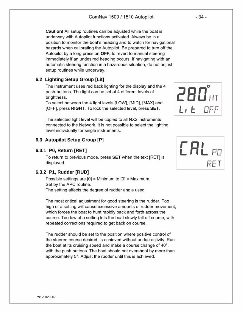
6.2 Lighting Setup Group [Lit]The instrument uses red back lighting for the display and the 4push-buttons. The light can be set at 4 different levels ofbrightness.To select between the 4 light levels [LOW], [MID], [MAX] and[OFF], press RIGHT. To lock the selected level, press SET.
The selected light level will be copied to all NX2 instrumentsconnected to the Network. It is not possible to select the lightinglevel individually for single instruments.
6.3 Autopilot Setup Group [P]
6.3.1 P0, Return [RET]To return to previous mode, press SET when the text [RET] isdisplayed.
6.3.2 P1, Rudder [RUD]Possible settings are [0] = Minimum to [9] = Maximum.Set by the APC routine.The setting affects the degree of rudder angle used.
The most critical adjustment for good steering is the rudder. Toohigh of a setting will cause excessive amounts of rudder movement,which forces the boat to hunt rapidly back and forth across thecourse. Too low of a setting lets the boat slowly fall off course, withrepeated corrections required to get back on course.
The rudder should be set to the position where positive control ofthe steered course desired, is achieved without undue activity. Runthe boat at its cruising speed and make a course change of 40°,with the push buttons. The boat should not overshoot by more thanapproximately 5°. Adjust the rudder until this is achieved.

ComNav 1500 / 1510 Autopilot - 35 -
PN: 29020007
6.3.3 P2, Damping of compass heading [SEA]Possible settings are [0] = Minimum to [9] = Maximum.Set by the APC routine.
This setting is a combination of yaw dead-band (compasssensitivity) and compass damping. The minimum setting mayonly be used under calm sea conditions to avoid unnecessaryrudder correction due to compass acceleration errors.
Smaller boats and high speed boats, which are subject to moreacceleration in lighter seas will have to use higher settings. Largerand more stable boats can use lower settings since there is lesscompass disturbance. Default setting should work on most boatsin light to moderate sea conditions. Following seas, no matter howrough, require lower settings to catch course error trendsquickly in order to minimize excessive yaw.
6.3.4 P3, Counter Rudder [CRD]Possible settings are [0] = Minimum to [9] = Maximum.Set by the APC routine.
This setting senses the rate of change of heading and givesadditional rudder corrections if the boat is rapidly falling off course,and backs off the rudder as a boat approaches the desiredheading. Its effect is to rapidly catch the tendency to yaw in aquartering sea, provide initially high rudder control when making alarge course change and to decelerate the swing of the bow, as aboat approaches the desired course.
Course holding with heavy and difficult to steer boats is greatlyimproved when using this feature. Insufficient counter rudder willallow the boat to overshoot on large course changes. Too muchwill cause unnecessary rudder corrections and a tendency to stopshort of coming to a new course, requiring several successivecorrections before easing up to the new heading.
To optimize counter rudder, initially set it to minimum and adjustthe rudder (see, [RUD] 5.3.2). Increment the counter rudder onestep at a time, while testing 40° course changes, until theboat achieves an overshoot of 1° to 2° or less.Remember, that any air in the hydraulic system will preventprecision control.

ComNav 1500 / 1510 Autopilot - 36 -
PN: 29020007
6.3.5 P4, Damping of wind [WSE]Possible settings are [0] = Minimum to [9] = Maximum.Default setting is [2].Damping of wind transducer. The factory default settingshould be adequate. In very heavy weather or unstablewind conditions, unnecessary corrections may be minimizedby increasing the setting.
6.3.6 P5 Automatic Trim Calibration [ATC]Possible settings are [0] = Minimum to [9] = Maximum.Set by the APC routine.
[ATC] is not critical. It constantly compares the course set againstthe course steered and slowly applies more rudder as necessary toreduce any errors to zero. Errors may be due to wind, waves orother unbalanced forces such as single screw operation of a twinscrew boat, an off-center tow or weather helm on a sailing boat,etc. If the trim time is set too high, it will take a long time toeliminate the course error. If it is set too low it can start to degradecourse stability.
In general, longer trim times (higher settings) should be set forlarge boats and sailing boats and shorter trim times (lowersettings) for small boats and high speed planning boats. Thefactory default setting should be acceptable for all but extremeapplications.
6.3.7 P6, Adaptive Control [ADC]Possible settings are [OFF] or [On].This function is reserved for future functions.
6.3.8 P7, Automatic Pilot Calibration [APC]Possible settings are [ON] or [OFF].
The APC routine automatically sets: [RUD], [SEA], [CRD], [ATC]and [RRS].The Autopilot will not function unless the boat pass the APCroutine. The APC will automatically determine and correct howwires and pipes are connected. It will also learn how the boatreacts on different rudder commands and automatically calibrateitself.To learn how to perform the APC function, see Sea Trials.

ComNav 1500 / 1510 Autopilot - 37 -
PN: 29020007
6.3.9 P8, Rudder Reduction Speed [RRS]Possible settings are [0] = Minimum to [9] = Maximum.Set by the APC routine.
The [RRS] controls the flow of the Pumpset. It will effect thePumpset, but not a solenoid valve steering system.
The [RRS] will be set to [5] after the APC routine is performed.It is then possible to increase or decrease the speed reductionof the Pumpset motor.
6.3.10 P9, Rudder angle limit [LIM]Possible settings are [00°-99°]. Default setting is [00°].An angle of 00° is the same as rudder angle limit disconnected(OFF).
Note! Make sure [LIM] is set to 00° (OFF) during installation.
The rudder angle limit sets maximum angle for the rudder. If thelimit is set to 45°, it is not possible to exceed a rudder angle 45° oneither port or starboard. Check the maximum rudder angle byturning the steering wheel to port and starboard and read themaximum angle. If the angle is greater on one side, decrease thesmallest angle by 3°, and enter that setting as the limit.

ComNav 1500 / 1510 Autopilot - 38 -
PN: 29020007
6.4 Alarm Setup Group [A]To silence an alarm, press any push button.
6.4.1 A0, Return [RET]To return to previous mode, press SET when the text [RET] isdisplayed.
6.4.2 A1, Pilot Course Alarm [PCA]Possible settings are [OFF] and [00°-99°]. Default setting is [OFF].
When the boat’s average course differs more than the [PCA]setting, the alarm will sound and the display will blink.
6.4.3 A2, Timer Watch Alarm [TMR]Possible settings are [OFF] or [On]. Default setting is [OFF].On = audible alarm activated.The audible alarm will sound every 5 minutes to alert the person onwatch to confirm and restart the timer, press any push-button. If notconfirmed within 1 minute, the optional external alarm buzzer, ifconnected to the NX2 Server, will sound for 1 minute, to alert therest of the crew.
6.4.4 A3, Cross Track Error Alarm [XTA]Possible settings are [0.00] = OFF to [9.99]. Default setting is[0.00].This function is only available in NAV function when the Autopilot isconnected to a NX2 Network and a navigator is connected to theNX2 Server.
If the pilot’s cross track error exceeds the set threshold of distanceof the track, the alarm will be activated.
6.4.5 A4, Push-Button Beep [KEY]Possible settings are [OFF] or [On]. Default setting is [ON].[On] = Sound when push buttons are pressed. [OFF] = No sound.

ComNav 1500 / 1510 Autopilot - 39 -
PN: 29020007
6.5 Compass Setup Group [C]Auto-deviation, auto-deviation-check and auto-deviation clear, areonly available if a NX2 compass transducer is connected. Theauto-deviation routine will automatically correct all possible faults,except alignment.
Note! As soon as you place any kind of ferrous items close to thecompass, the auto-deviation and auto-deviation check routinesshould be repeated. So if you have packed your boat for thevacation, think about where you place ferrous items in relation tothe compass transducer.
6.5.1 C0, Return [RET]To return to previous mode, press SET when the text [RET] isdisplayed.
6.5.2 C1, Magnetic Heading [MAG]Possible settings are [OFF] and [On]. Default setting is [OFF].[On] = All headings will be magnetic.[OFF] = All headings will be true, i.e. corrected for local variationset in C2, Local variation [VAR]. This is local setting.
6.5.3 C2, Local Magnetic Variation [VAR]Possible settings are [+/-00.0°-99.9°]. Default setting is [00.0�]Easterly variation = underlining ( _ ) sign.Westerly variation = minus ( - ) sign.The local magnetic variation is usually printed in the sea chart.
6.5.4 C3, Auto-Deviation [Auto DEV]This function is used to automatically correct the deviation of yourcompass.
Take the boat into a slow turn, in calm sea and away from otherboats or obstructions. There is no need to perform a perfect circle.
When steady, select C3 [Auto DEV] and press SET to start. Thepresent "uncorrected" compass heading is displayed and thecompass auto-deviation is in progress. Turn the boat in a 1 ¼circle, and when ready press SET again.
If successful, the text [CAL C3] [Auto DEV] will be displayed.

ComNav 1500 / 1510 Autopilot - 40 -
PN: 29020007
If not successful, an error messages can be displayed:• [Err 15]: Make sure an Autopilot function is not activated and
carry out the auto-deviation procedure again.• [Err 16]: Auto-Deviation is not possible, because a NMEA
compass is selected as compass for the NX2 Network.• [Err 17]: The 1 ¼ turn was not performed or the compass is
affected by strong magnetic distortion.You may interrupt the auto-deviation procedure at any time bypressing LEFT and RIGHT together.To check the auto-deviation, carry out the auto-deviation checkroutine.
6.5.5 C4, Check Auto-Deviation [Auto CHK]This function is used to check your auto-deviation.
The result of [Auto CHK] will be compared with [Auto DEV]. If thedeviation is less than 1.5°, the average value from the comparisonbetween [Auto DEV] and [Auto CHK] will be stored.
Take the boat into a slow turn, in calm sea and away from otherboats or obstructions. There is no need to perform a perfect circle.When steady, select C4 [Auto CHK] and press SET to start.The present compass heading is displayed and the compassAutodeviation check is in progress. Turn the boat in a 1 ¼ circle.To end the routine, press SET again.If successful, the text [CAL C4] [Auto CHK] will be displayed.If not, [ERR 17] or [ERR 19] will appear, i.e. the difference betweenthe last auto-deviation and this autodeviation check was too greatto be accepted.Make a new auto-deviation-check, and if you still get [ERR 19],make a new auto-deviation, since the last one was probablydisturbed.
6.5.6 C5, Clear Auto-Deviation [Auto CLR]To clear the calibration created by the auto-deviation, select C5[Auto CLR], and press SET.
MIN 400°
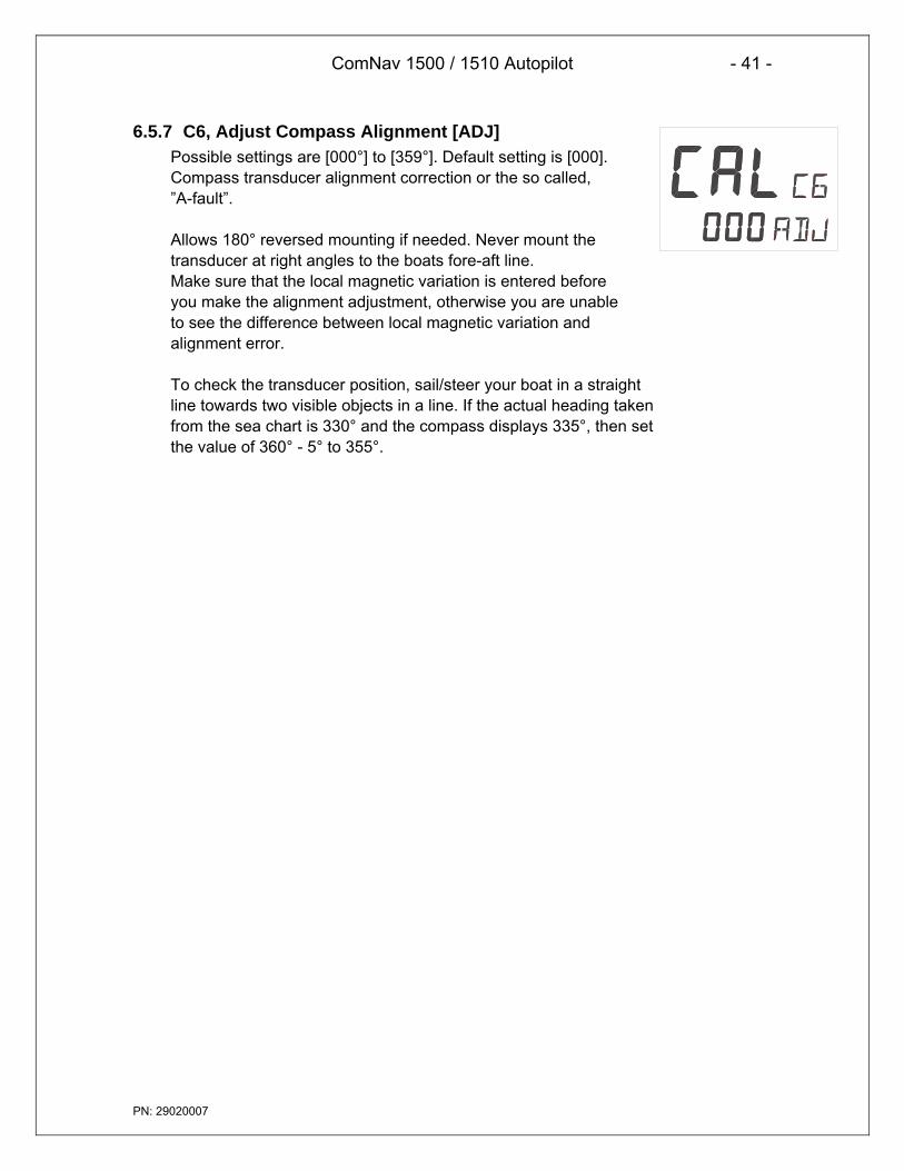
ComNav 1500 / 1510 Autopilot - 41 -
PN: 29020007
6.5.7 C6, Adjust Compass Alignment [ADJ]Possible settings are [000°] to [359°]. Default setting is [000].Compass transducer alignment correction or the so called,”A-fault”.
Allows 180° reversed mounting if needed. Never mount thetransducer at right angles to the boats fore-aft line.Make sure that the local magnetic variation is entered beforeyou make the alignment adjustment, otherwise you are unableto see the difference between local magnetic variation andalignment error.
To check the transducer position, sail/steer your boat in a straightline towards two visible objects in a line. If the actual heading takenfrom the sea chart is 330° and the compass displays 335°, then setthe value of 360° - 5° to 355°.
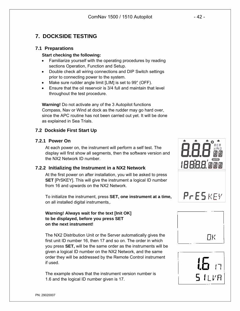
ComNav 1500 / 1510 Autopilot - 42 -
PN: 29020007
7. DOCKSIDE TESTING
7.1 PreparationsStart checking the following:• Familiarize yourself with the operating procedures by reading
sections Operation, Function and Setup.• Double check all wiring connections and DIP Switch settings
prior to connecting power to the system.• Make sure rudder angle limit [LIM] is set to 99° (OFF).• Ensure that the oil reservoir is 3/4 full and maintain that level
throughout the test procedure.
Warning! Do not activate any of the 3 Autopilot functionsCompass, Nav or Wind at dock as the rudder may go hard over,since the APC routine has not been carried out yet. It will be doneas explained in Sea Trials.
7.2 Dockside First Start Up
7.2.1 Power OnAt each power on, the instrument will perform a self test. Thedisplay will first show all segments, then the software version andthe NX2 Network ID number.
7.2.2 Initializing the Instrument in a NX2 NetworkAt the first power on after installation, you will be asked to pressSET [PrSKEY]. This will give the instrument a logical ID numberfrom 16 and upwards on the NX2 Network.
To initialize the instrument, press SET, one instrument at a time,on all installed digital instruments,.
Warning! Always wait for the text [Init OK]to be displayed, before you press SETon the next instrument!
The NX2 Distribution Unit or the Server automatically gives thefirst unit ID number 16, then 17 and so on. The order in whichyou press SET, will be the same order as the instruments will begiven a logical ID number on the NX2 Network, and the sameorder they will be addressed by the Remote Control instrumentif used.
The example shows that the instrument version number is1.6 and the logical ID number given is 17.

ComNav 1500 / 1510 Autopilot - 43 -
PN: 29020007
Warning! Do not activate any Autopilot functions until DocksideTesting and Sea Trials APC routine have been performed.
7.2.3 Re-Initializing the InstrumentIf two instruments have been given the same ID number bymistake, you must re-initialize the instruments to avoid Networkdisturbance and blockage of data.
To re-initialize the instrument, be prepared to press Left and Righttogether during the short power up sequence, i.e. when versionand ID numbers are displayed.
The display test is then re-started on all instruments and you willbe asked to press SET on one instrument at the time as explained above.
Note! If you do not succeed to re-initialize, we suggest youdisconnect (just pull out the connection plug) on all, except one ofthe instruments that had the same ID number, then re-install theinstruments and repeat the above procedure.Run the procedure as described in Dockside First Start Up.
7.3 Remove Air from SystemFilling the hydraulic system (for reversing Pumpsets and liner drives only).Select PWR ST function by pressing MODE until the page-arrow appears underPWR ST.To activate the Autopilot, press SET.Press and hold LEFT or RIGHT until the Pumpset begin to run and the ruddermoves.
If port rudder is given when you press starboard (RIGHT) push-button, and viceversa, ignore the reversal. It will be corrected automatically when doing the APCroutine at Sea Trials.
It may take time before the steering begins to move due to air in the system.Continue to press and hold the push-button until the steering reaches its stops.Then reverse direction with the opposite push-button. Repeat this procedure 10times or more until the system appears to move smoothly.
After 5 or 10 minutes of this purging, let the system rest so that entrained air cansettle out of the oil. After 5 minutes of rest, repeat the above procedure.
(With linear drives the wheel cannot be turned to assist purging unless the bypassvalve is temporarily disconnected. Make sure that the valve wiring is reconnectedbefore further testing. Also, with linear drives, when attempting to get air out of thesystem make sure the flow adjusting wheel is set at a mid flow position).

ComNav 1500 / 1510 Autopilot - 44 -
PN: 29020007
Air in the system may cause noisy Pumpset operation. When the Pumpsetbecomes quieter and the steering moves smoothly and the linear drive respondsinstantly in both directions, it may be assumed that most air is out of the system.To check that all air is removed, select power steer function and try to turn thesteering wheel. In this function the steering wheel should be stiff. If you can turn thewheel a certain amount with a increasing pressure as a result, there is still air in thesystem.
Continue to ventilate the system until the steering wheel is stiff before you proceedwith the sea trials.
Do not attempt to activate the Autopilot in other functions than power steer, until allair is out of the system. Sloppy course holding will result if you do. The very last airremoval will be done as the boat is tested underway.
7.4 Adjust the Pumpset Flow RateThe Autopilot is capable of automatically adjusting the flow rate of the Pumpset. Ifusing a fixed flow rate Pumpset there is no adjustment of the flow rate required.However, if using a variable flow rate Pumpset, adjust the flow rate of the Pumpsetfor approximately 14 seconds hardover to hardover time or slower for best steeringaccuracy.
7.5 Functional TestsRead Operation, Function and Set Up of the manual to familiarize yourself with theoperating procedures. Try the different modes at the dock to verify that all systemsare working and ready for sea trials.Do not try to make course changes in pilot modes as the rudder may go hardover,since the [APC] Pilot Calibration has not been conducted yet.
When you finished the Dockside Testing, perform the Sea Trials.

ComNav 1500 / 1510 Autopilot - 45 -
PN: 29020007
8. SEA TRIALS
8.1 PreparationsTake your boat out at half speed to calm seas away from other boats orobstructions to run the sea trials. Then proceed as per below.Warning! Do not activate any of the Autopilot functions (Compass, Nav or Wind) atdockside as the rudder may go hard over, since the APC routine has not beencarried out yet.
8.2 Compass CalibrationEnter the compass calibration.Note! If you are using an existing NX2 Compass transducer that already has beencompensated, it is not necessary to run the auto-deviation [Auto DEV] procedureagain.Local Magnetic Variation:Run the calibration routine local variation [VAR].Automatic Compass Compensation:Run the calibration procedure auto-deviation [Auto DEV].Automatic Compass CheckRun the calibration procedure auto-deviation-check [Auto CHK].Misalignment CorrectionRun the calibration procedure compass alignment [ADJ].
8.3 Automatic Pilot Calibration [APC]The Autopilot will not function unless the boat pass the APC routine. The APC willautomatically determine and correct how wires and pipes are connected. It will alsolearn how the boat reacts on different rudder commands and automatically calibrateitself.
The APC routine automatically sets: [RUD], [SEA], [CRD], [ATC] and [RRS].
Select P7 [APC]. To unlock, press SET. To change to [On], press LEFT or RIGHT.To activate the APC, press SET.
All 4 page arrows at top of display will now be lit to confirm the APC procedure is inaction.The boat should automatically turn slightly to port and starboard and return tooriginal course.

ComNav 1500 / 1510 Autopilot - 46 -
PN: 29020007
If the APC fails: Error message 34 (calibration failure) is displayed. This is mostlikely caused by too much air still in the system. To escape the error message,press any push-button. Revert to 10.3. ”How to remove air from the system”. Note!You can ”help” the APC process by manually pulling the steering wheel or tiller insame direction as APC turns the boat to pass the APC.
If the APC is successful: All 4 page-arrows disappear, the instrument leaves thesetup mode and returns to standby mode automatically.
Note! You may interrupt the APC routine at any time by a press on SET.
Congratulations, your Autopilot calibration is done.Now go ahead and activate the Autopilot and enjoy the NX2 performance.

ComNav 1500 / 1510 Autopilot - 47 -
PN: 29020007
9. FINE TUNINGThe factory default settings and the APC routine will provide acceptableperformance for most boats, but each boat has different steering characteristicsand some fine tuning may be necessary for optimum performance.
For individual settings referred to below, see the setup section.
The tests should be performed under fairly calm sea conditions with minimal windor tide. If wind and/or tide are unavoidable set a course for minimum effects fromthese causes. It is recommended that these sea trials not be done in restricted orbusy waters.
Step by Step Instructions How to Fine Tune the Autopilot:
1. Check that Dockside Testing, Sea Trials including the APC routine has beendone. If not, go back and make sure they are done.
2. Activate the Autopilot on a course and ensure that it holds without excessiveundersteering or oversteering.
3. With the boat travelling in a straight line at its normal cruising speed in calmwater, activate the Autopilot compass function. Make a 40° course changeusing the LEFT or RIGHT and the boat should not overshoot by more than 1° to2°. Continue making 40° course changes while adjusting the Rudder [RUD]setting until the boat overshoots the correct course a few times prior to settingon the course. This is the optimal [RUD] setting that can be used on the boat atthe current cruising speed and load, in calm waters.
4. Continue making 40°course changes while slowly increasing the CounterRudder [CRD] setting, until the boat settles onto course with only one overshootof 3° or less. On some boats, the [RUD] setting may have to be decreased byone position to get the boat to control properly. The [RUD] and [CRD] settingsare set to the maximum combined settings that should be used on the boat atthat speed and under the existing sea conditions.
The [RUD] and [CRD] settings may need to be increased in rough weather. Thehigher the [CRD] setting relative to the [RUD] setting for calm weather, the lessit will need to be increased in rough weather. As the boat's speed decreases,the rudder becomes less effective.
The [RUD] and [CRD] settings may need to be increased as the speeddecreases. The higher the [CRD] setting relative to the [RUD] setting, the less itwill need to be increased at lower speeds.
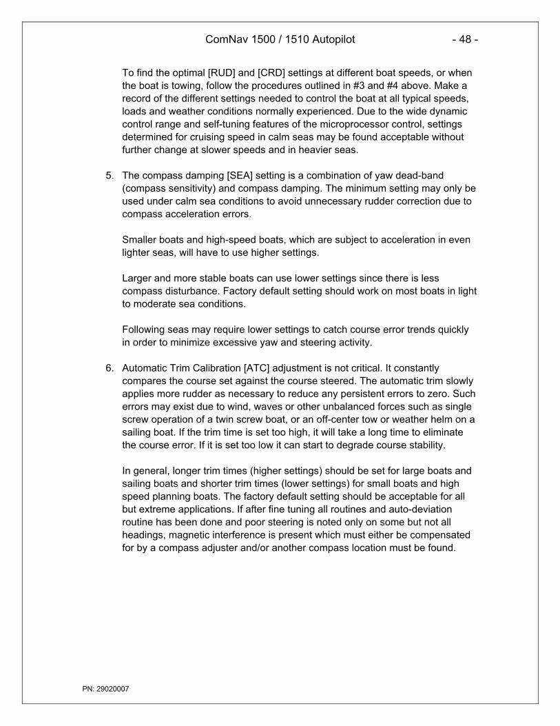
ComNav 1500 / 1510 Autopilot - 48 -
PN: 29020007
To find the optimal [RUD] and [CRD] settings at different boat speeds, or whenthe boat is towing, follow the procedures outlined in #3 and #4 above. Make arecord of the different settings needed to control the boat at all typical speeds,loads and weather conditions normally experienced. Due to the wide dynamiccontrol range and self-tuning features of the microprocessor control, settingsdetermined for cruising speed in calm seas may be found acceptable withoutfurther change at slower speeds and in heavier seas.
5. The compass damping [SEA] setting is a combination of yaw dead-band(compass sensitivity) and compass damping. The minimum setting may only beused under calm sea conditions to avoid unnecessary rudder correction due tocompass acceleration errors.
Smaller boats and high-speed boats, which are subject to acceleration in evenlighter seas, will have to use higher settings.
Larger and more stable boats can use lower settings since there is lesscompass disturbance. Factory default setting should work on most boats in lightto moderate sea conditions.
Following seas may require lower settings to catch course error trends quicklyin order to minimize excessive yaw and steering activity.
6. Automatic Trim Calibration [ATC] adjustment is not critical. It constantlycompares the course set against the course steered. The automatic trim slowlyapplies more rudder as necessary to reduce any persistent errors to zero. Sucherrors may exist due to wind, waves or other unbalanced forces such as singlescrew operation of a twin screw boat, or an off-center tow or weather helm on asailing boat. If the trim time is set too high, it will take a long time to eliminatethe course error. If it is set too low it can start to degrade course stability.
In general, longer trim times (higher settings) should be set for large boats andsailing boats and shorter trim times (lower settings) for small boats and highspeed planning boats. The factory default setting should be acceptable for allbut extreme applications. If after fine tuning all routines and auto-deviationroutine has been done and poor steering is noted only on some but not allheadings, magnetic interference is present which must either be compensatedfor by a compass adjuster and/or another compass location must be found.

ComNav 1500 / 1510 Autopilot - 49 -
PN: 29020007
9.1 Optional Fine Tuning for Special ApplicationsPotentiometer adjustments, functionality on Distribution Unit.
VR1: Anti-hunt control for rudder: Inappropriate adjustment could result in steeringoscillations or degradation of steering performance. The potentiometer is factoryset at minimum deadband setting. Adjustment of this potentiometer can be used toadjust deadband for rudder response, compensating for slack in steering system,and/or lack of stiffness in cylinder support.
VR2: Analog External Rudder Angle Indicator Instrument deflection adjustment (ifapplicable).
VR3: Analog External Rudder Angle Indicator Instrument offset adjustment (ifapplicable).
VR4: Factory set; counter rudder delay primarily used on large vessels (over 100’ inlength).
VR5: Control head digital display Rudder Angle Indicator offset adjustment;potentiometer is factory set; to be minor adjusted by Autopilot technicians if ruddertransmitter linkage can not be adjusted; inappropriate large adjustments couldresult in poor Autopilot performance; do not adjust when in full follow up steeringmode. This is not available on 1510 Distribution Unit.
VR6: Current limit adjustment for servo drive; potentiometer is factory set; do notadjust.

ComNav 1500 / 1510 Autopilot - 50 -
PN: 29020007
10. PROBLEM SOLVING
10.1 GeneralBefore you contact your ComNav dealer, and for them to give you betterservice, please check the following points and make a list of:• All connected instrument and transducers, including their software versions.• NX2 Network ID numbers for each instrument (displayed at power up).
In most cases, the reason for faults in electronic equipment is poor installation.Therefore, always first check for the following:
• Installation and connections are made per instructions for instruments andtransducers.
• Screw terminals are carefully tightened.• There is no corrosion on any connection points.• No loose ends in the wires, causing short cuts to adjacent wires.• Cables for damage and that none are squeezed or worn.• Battery voltage is sufficient, should be at least 11 V DC.• The fuse is not blown and that the circuit-breaker has not opened.• The fuse is of the right type.• Two instruments do not have the same ID number.
10.2 Symptom - Cause - ActionIn the table below, causes marked [ * ] are more likely to occur during installation orwhen rewiring has taken place.
SYMPTOM CAUSE ACTIONAutopilot does not turn off. * Voltage below minimum. Make sure 12/24 volts is applied to
battery terminals in Distribution Unit.* Voltage not applied. Make sure 12/24 volts is applied to
battery terminals in Distribution Unit.* Voltage polarity is reversed. Make sure + and – is applied to
correct terminals.* Boats safety switch is open. Close the safety switch.
Autopilot does not turn on.
* Fuse burned out. Check and replace fuse asnecessary, located in the DistributionUnit.
Slow blow (high current) fuse inDistribution Unit is blown.
Replace fuse. If fuse regularly blows,check for excessive rudder load ormechanical defects in steeringsystem.
Autopilot turns on, but thePumpset doesn’t run
Rudder speed set too low. Decrease RRS setting.

ComNav 1500 / 1510 Autopilot - 51 -
PN: 29020007
SYMPTOM CAUSE ACTIONMotor Pumpset turns but therudder doesn’t move.
Pumpset drive section inDistribution Unit may have failedto open.
Replace transistors, integratedcircuits or entire circuit board.
Broken or loose motor coupling Replace or tighten coupling asnecessary.
Pumpset contamination. Clean or replace Pumpset.Low battery voltage. Automaticshut-off in case of voltage lowerthan 10.5V for 12V battery and21.5V for 24V battery.
Turn Autopilot off and chargebatteries or correct voltage loss.When proper voltage restored,restart Autopilot.
Poor wiring connection. Check for voltage drop and repair.Power wiring is undersized. Replace wiring with correct gauge.
Blinking [Low Bat] on bottomline of display.
Voltage drop across circuitbreaker.
Make sure 25Amp circuit breaker isused.
APC routine not performed. Pilot calibration “APC” required.Power transistors in DistributionUnit may be shorted.
Replace transistors or entire circuitboard.
Rudder Transmitter linkagedisconnected.
Re-connect and align as perInstallation Instructions.
Rudder Transmitter wiringshorted or open circuit.
Check and repair wiring asnecessary.
When Autopilot engaged,rudder goes hardover.
Rudder Transmitter potdefective.
Replace.
Autopilot wanders on someheadings.
Magnetic interference is present.The worst steering is usually onnortherly headings in thenorthern hemisphere andsoutherly headings in thesouthern hemisphere.
Perform Auto-Deviation-Clear [CLR]and Auto-Deviation [DEV] again, ortry another compass location.Investigate for magneticdisturbances around compass, e.g.Masses of steel, motors,loudspeakers, etc.
Severe magnetic interference. Choose another compass location.Air in hydraulics. Fill and purge the steering system.Slack in the steering system. Repair any loose or worn parts.
Autopilot wanders on allheadings.
Rudder Transmitterpotentiometer is “noisy” orintermittent.
Replace rudder potentiometer.
Compass damaged; intermittentwiring connections.
Repair any loose or worn parts;recheck and connect wiring.
Slow wander means ruddercontrol is set too low(understeering).
Increase Autopilot setting [P1] [RUD]
Fast wander means ruddercontrol is set too high(oversteering).
Decrease Autopilot setting [P1][RUD]
Excess rudder load. Reduce rudder friction, increasesteering cylinder size, increasepower of the Pumpset.
Rudder movement erratic.
Air in system. Check for leaks and bleed thesystem.
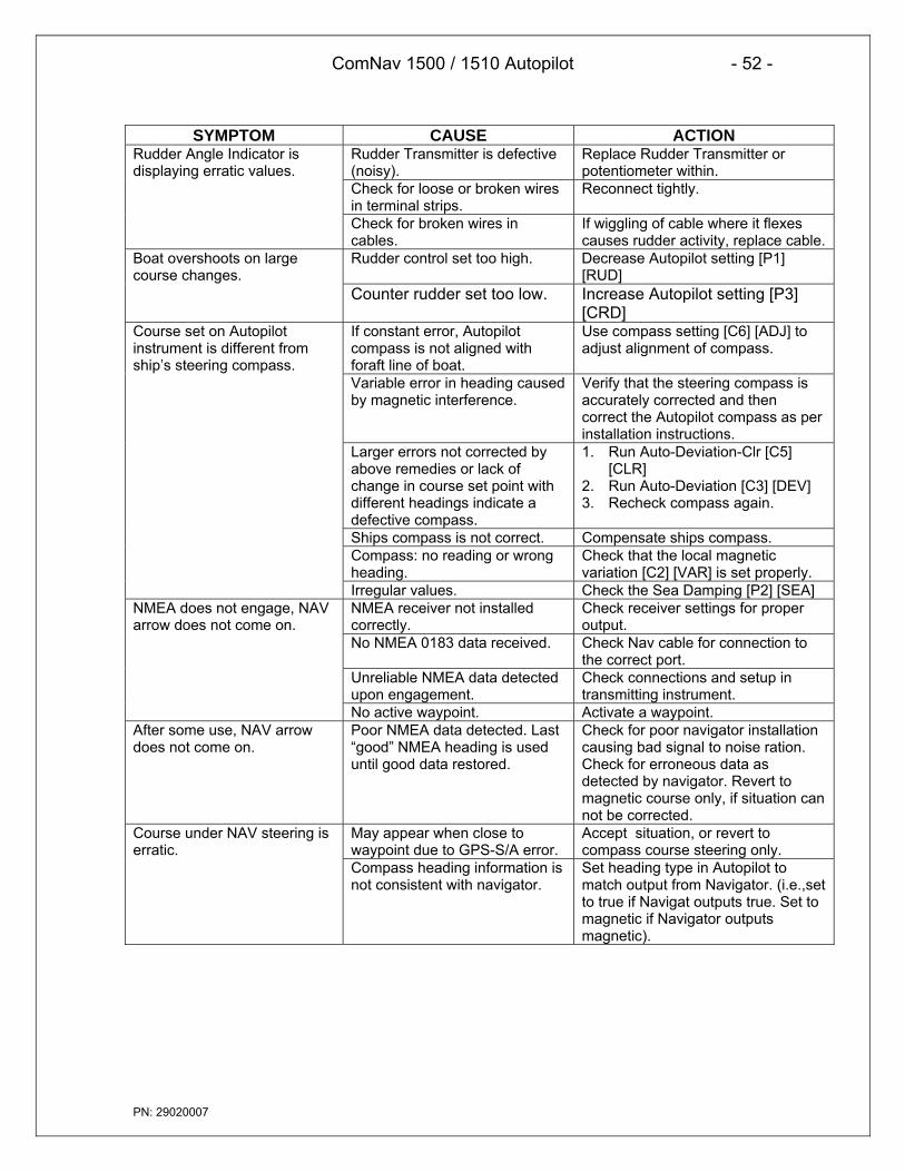
ComNav 1500 / 1510 Autopilot - 52 -
PN: 29020007
SYMPTOM CAUSE ACTIONRudder Transmitter is defective(noisy).
Replace Rudder Transmitter orpotentiometer within.
Check for loose or broken wiresin terminal strips.
Reconnect tightly.
Rudder Angle Indicator isdisplaying erratic values.
Check for broken wires incables.
If wiggling of cable where it flexescauses rudder activity, replace cable.
Rudder control set too high. Decrease Autopilot setting [P1][RUD]
Boat overshoots on largecourse changes.
Counter rudder set too low. Increase Autopilot setting [P3][CRD]
If constant error, Autopilotcompass is not aligned withforaft line of boat.
Use compass setting [C6] [ADJ] toadjust alignment of compass.
Variable error in heading causedby magnetic interference.
Verify that the steering compass isaccurately corrected and thencorrect the Autopilot compass as perinstallation instructions.
Larger errors not corrected byabove remedies or lack ofchange in course set point withdifferent headings indicate adefective compass.
1. Run Auto-Deviation-Clr [C5][CLR]
2. Run Auto-Deviation [C3] [DEV]3. Recheck compass again.
Ships compass is not correct. Compensate ships compass.Compass: no reading or wrongheading.
Check that the local magneticvariation [C2] [VAR] is set properly.
Course set on Autopilotinstrument is different fromship’s steering compass.
Irregular values. Check the Sea Damping [P2] [SEA]NMEA receiver not installedcorrectly.
Check receiver settings for properoutput.
No NMEA 0183 data received. Check Nav cable for connection tothe correct port.
Unreliable NMEA data detectedupon engagement.
Check connections and setup intransmitting instrument.
NMEA does not engage, NAVarrow does not come on.
No active waypoint. Activate a waypoint.After some use, NAV arrowdoes not come on.
Poor NMEA data detected. Last“good” NMEA heading is useduntil good data restored.
Check for poor navigator installationcausing bad signal to noise ration.Check for erroneous data asdetected by navigator. Revert tomagnetic course only, if situation cannot be corrected.
May appear when close towaypoint due to GPS-S/A error.
Accept situation, or revert tocompass course steering only.
Course under NAV steering iserratic.
Compass heading information isnot consistent with navigator.
Set heading type in Autopilot tomatch output from Navigator. (i.e.,setto true if Navigat outputs true. Set tomagnetic if Navigator outputsmagnetic).

ComNav 1500 / 1510 Autopilot - 53 -
PN: 29020007
10.3 NX2 Network Error Messages with Cause and RemedyIf an error message [Err #] is displayed, an error has been detected by the NX2Network. The message can assist you to diagnose the cause and remedy the error.
To escape from an error message, press any push-button. If not possible toescape, reset power (turn off and on again), then remedy the situation assuggested below.
Note! For errors marked with [*], contact your ComNav dealer or the factory inorder to return the unit for rectification.
NO. MESSAGE AND CAUSE REMEDY *01 Activated watchdog timeout Reset power. *02 NX2 Network data frames are
missing.Check connections and setup.
03 No data received within approx. 10sec.
Check connections.
04 EEPROM read. Reset power. *05 EEPROM write. Reset power. *06 RAM memory error. Reset power. *07 Auto-log full, in GPS Compass. Clear Auto-log memory.08 Break reset. Reset power. *09 EEPROM auto initiation, or NMEA
transmit fail. (NX2 Server only).Reset power. *
10 Range error, input e.g. 17° 70’ = toomany minutes.
Correct input format.
11 Remote control setup error.Command can not be executed.
Check connections and settings.
12 No response from Navigator Check navigator connection andsettings.
13 Waypoint not defined. Define a waypoint.14 Impossible command when used
with an external NMEA navigator.Use only possible command.
15 Impossible command when inAutopilot mode.
Use only possible commands.
16 Auto-deviation is not possible. Check for extreme magnetic field,upside down mounting oftransducer or wrong transducertype.
17 Auto-deviation check failed. 1-¼ turn not complete or extrememagnetic disturbance.
18 Auto-deviation. Function denied. Function denied since compass isbusy with the Auto-deviationroutine.

ComNav 1500 / 1510 Autopilot - 54 -
PN: 29020007
NO. MESSAGE AND CAUSE REMEDY *19 Auto-deviation failure. Error larger than 1.5°. The boat
probably hit a wave during the turn.Redo.
20 GPS to CPU communication error. Reset power. *21 GPS acquisition failure (time out). Maximum allowed time for
searching satellites. E.g. When tryto navigate indoors. Check GPSantenna location.
22 CPU to GPS communication error. Reset power. *23 DGPS (RTCM) data ignored. Change the DGPS (RTCM) setting.24 GPS bad fix, no fix position (time
expired at one-fix).Check GPS antenna location.
25 No Autopilot response.Object is not connected.
Check wiring connections and fuse.
26 The unit is not allowed to power upBecause there is too high inputvoltage.
Check input voltage. *
27 Extended object server busy orerror.
Set one GPS Navigator instrumentto master.
28 Route command error. ThewaypointBank memory is full.
Clear waypoint bank to makespace.
29 DGPS mode is interrupted. Check the DGPS receiver.
42 Bad transducer input / badmeasurement.
Reset power. *
NX2 Autopilot Distribution Unit30 General Autopilot failure Reset
power.Reset Power. *
31 Autopilot compass input failure inAutopilot standalone connection.
Check compass connection atAutopilot Distribution Unit.
32 Autopilot compass input failure inAutopilot Nexus Networkconnection.
Check compass connection atNX2 Server or at the CompassData instrument.
33 Received wind data input failure. Check wind wire connection.34 Autopilot calibration failure. Check for air in the system and redo
the APC routine again in calmwater.
35 Navigation data not available inAutopilot stand alone connection.
Check NMEA input connections andsettings in the navigator.
36 Navigation data not available inAutopilot Nexus Networkconnection.
Check connections and navigatorsettings.
37 Autopilot Network re-initialization. Check connections and wire gauge.
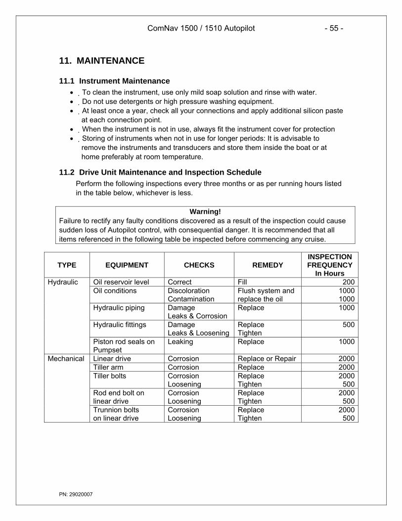
ComNav 1500 / 1510 Autopilot - 55 -
PN: 29020007
11. MAINTENANCE
11.1 Instrument Maintenance• To clean the instrument, use only mild soap solution and rinse with water.• Do not use detergents or high pressure washing equipment.• At least once a year, check all your connections and apply additional silicon paste
at each connection point.• When the instrument is not in use, always fit the instrument cover for protection• Storing of instruments when not in use for longer periods: It is advisable to
remove the instruments and transducers and store them inside the boat or athome preferably at room temperature.
11.2 Drive Unit Maintenance and Inspection SchedulePerform the following inspections every three months or as per running hours listedin the table below, whichever is less.
Warning!Failure to rectify any faulty conditions discovered as a result of the inspection could causesudden loss of Autopilot control, with consequential danger. It is recommended that allitems referenced in the following table be inspected before commencing any cruise.
TYPE EQUIPMENT CHECKS REMEDYINSPECTIONFREQUENCY
In HoursOil reservoir level Correct Fill 200Oil conditions Discoloration
ContaminationFlush system andreplace the oil
10001000
Hydraulic piping DamageLeaks & Corrosion
Replace 1000
Hydraulic fittings DamageLeaks & Loosening
ReplaceTighten
500
Hydraulic
Piston rod seals onPumpset
Leaking Replace 1000
Linear drive Corrosion Replace or Repair 2000Tiller arm Corrosion Replace 2000Tiller bolts Corrosion
LooseningReplaceTighten
2000500
Rod end bolt onlinear drive
CorrosionLoosening
ReplaceTighten
2000500
Mechanical
Trunnion boltson linear drive
CorrosionLoosening
ReplaceTighten
2000500
ComNav 1500 / 1510 Autopilot - 56 -
PN: 29020007
12. WARRANTY INFORMATIONLIMITED WARRANTY AGREEMENT
Congratulations, you have purchased sophisticated and sensitive marine equipment (the“Equipment”) manufactured by ComNav Marine Ltd. of #15 – 13511 Crestwood Place, Richmond,British Columbia, Canada, V6V 2G1 (“ComNav”).
LIMITED ONE YEAR WARRANTY. ComNav warrants to the Purchaser, provided that therecommended installation and maintenance procedures set forth in the manual that has beenprovided with the Equipment (the “Manual”) have been followed, and subject always to the otherprovisions of this Agreement, that the Equipment is free from defects in workmanship and materialsunder normal use and service and will perform substantially in accordance with the specifications setforth in the Manual for a period of one (1) year from the date of purchase of the Equipment by thePurchaser.
EXTENDED THREE YEAR LIMITED WARRANTY. If;
(a) the Equipment is installed:
(i) by an authorized ComNav Dealer; or
(ii) by someone other than an authorized ComNav Dealer, and suchinstallation has been inspected by an Authorized ComNav Dealer;and
(b) the Limited Warranty Registration Card has been returned to ComNav within 14 days ofthe date of purchase of the Equipment by the Purchaser with Part I thereof having beencompleted by the Purchaser, and with the Extended Limited Warranty Card havingbeen completed and signed by an authorized ComNav Dealer and returned to ComNavwithin 14 days of that inspection;
ComNav warrants to the Purchaser that the Equipment is free from defects in workmanship andmaterials under normal use and service and will perform substantially in accordance with thespecifications set forth in the Manual for a period of three (3) years from the date of purchase of theEquipment, subject to the other provisions of this Agreement.
NO OTHER WARRANTIES. TO THE MAXIMUM EXTENT PERMITTED BY APPLICABLE LAW,COMNAV DISCLAIMS ALL OTHER WARRANTIES AND CONDITIONS, EITHER EXPRESSED ORIMPLIED, STATUTORY OR OTHERWISE WITH RESPECT TO THE EQUIPMENT, INCLUDINGBUT NOT LIMITED TO IMPLIED WARRANTIES OR CONDITIONS OF MERCHANTABILITY ANDFITNESS FOR THE ORDINARY PURPOSES FOR WHICH THE EQUIPMENT IS USED ORFITNESS FOR A PARTICULAR PURPOSE AND ANY OTHER OBLIGATIONS ON THE PART OFCOMNAV, ITS EMPLOYEES, SUPPLIERS, AGENTS, OR REPRESENTATIVES.
NO LIABILITY FOR CONSEQUENTIAL DAMAGES. TO THE MAXIMUM EXTENTPERMITTED BY APPLICABLE LAW, IN NO EVENT SHALL COMNAV, ITS EMPLOYEES,SUPPLIERS, OR REPRESENTATIVES BE LIABLE FOR ANY DAMAGES WHATSOEVER,INCLUDING WITHOUT LIMITATION DAMAGE FROM COLLISION WITH OTHER VESSELS OROBJECTS, INJURY TO ANY PERSON OR PERSONS, DAMAGE TO PROPERTY, LOSS OFINCOME OR PROFIT, BUSINESS INTERRUPTION, OR ANY OTHER CONSEQUENTIAL,INCIDENTAL, RESULTING PUNITIVE, OR SPECIAL DAMAGES ARISING OUT OF THE USE OFOR INABILITY TO USE THE EQUIPMENT, INCLUDING THE POSSIBLE FAILURE ORMALFUNCTION OF, OR DEFECTS IN THE EQUIPMENT, OR ANY PART THEREOF, EVEN IFCOMNAV HAS BEEN ADVISED OF THE POSSIBILITY OF SUCH DAMAGES. SOMESTATE/JURISDICTIONS DO NOT ALLOW THE EXCLUSION OR LIMITATION OFCONSEQUENTIAL OR INCIDENTAL DAMAGES, SO THE ABOVE LIMITATION MAY NOT APPLYTO THE PURCHASER.
REMEDIES NOT TRANSFERABLE. The Purchaser’s remedies under this Agreement only applyto the original end-user of the ComNav Equipment, being the Purchaser, and only apply to theoriginal installation of the Equipment. The Purchaser’s remedies under this Agreement are nottransferable or assignable by the Purchaser to others in whole or in part.

ComNav 1500 / 1510 Autopilot - 57 -
PN: 29020007
NOTICE OF DEFECT. The Limited Warranty and the Extended Warranty will not apply with respect to anydefective Equipment unless written notice of such defect is given to ComNav, by mail to the address forComNav set forth above, or by facsimile to ComNav at 1-604-872-3955, and is received by ComNav within10 days of the date upon which the defect first became known to the Purchaser. Notices sent by mail will bedeemed to be received by ComNav on the seventh (7th) day first following the date of posting in NorthAmerica and on the tenth (10th) day next following the date of posting anywhere else in the world. Noticessent by facsimile will be deemed to be received by ComNav on the date of transmission with appropriateanswerback confirmation.
WARRANTY LIMITATIONS. Reversing Pumps & Motors, Hydraulic Linear Actuators, WatchAlarms & Motor Control Boxes which may comprise part of the Equipment are warranted by ComNavfor a period of two (2) years under the Extended Limited Warranty described above. All RemoteControls, Remote Cables, Jog Switches, Analog meters (rudder angle indicators), Rudder AngleIndicator Systems & Accessories, Magnetic Compasses & Accessories, Constant Running Pumps,Engine Driven Pumps, Hydraulic Manifolds & Hydraulic Steering are warranted by ComNav for aperiod of one (1) year under the Limited Warranty described above.
IMPLIED WARRANTIES. Any implied warranties with respect to the Equipment are limitedto one (1) year. Some states/jurisdictions do not allow limitations on how long an impliedwarranty lasts, so the above limitation may not apply to the Purchaser.
1. CUSTOMER REMEDIES. ComNav’s entire liability and the Purchaser’s exclusive remedyagainst ComNav for the defective Equipment shall be, at ComNav’s option, either: (a) repair orreplacement of the defective Equipment under the warranties set forth in this Agreement, or, (b)refund of the purchase price of the defective Equipment, all pursuant to and in accordance with theconditions set forth below:
(a) If the Equipment, or any part thereof, proves to be defective within the relevant warrantyperiod, the Purchaser shall do the following:
(b) contact ComNav by phoning 1-604-207-1600 to discuss the nature of the problem and obtainshipping instructions (many times a satisfactory solution can be reached without returningthe item); and prepare a detailed written statement of the nature of the circumstances of thedefect, to the best of the Purchaser’s knowledge, including the date of purchase of theEquipment, the place of purchase, the name and address of the installer, and thePurchaser’s name, address and telephone number to be sent, along with proof of purchase,to ComNav;
2. If upon examination by either ComNav or an authorized ComNav Dealer, the defect isdetermined to result from defective workmanship or material and if the defect has occurredwithin the relevant warranty period set forth above, the Equipment or the defective parts thereofshall be repaired or replaced, at ComNav’s sole option, without charge, and shall be returned tothe Purchaser at ComNav’s expense. Return delivery will be by the most economical means.Should the Purchaser require that the Equipment be returned by a faster method, the costsincurred by the expedient delivery will be pre-paid by the Purchaser;
3. No refund of the purchase price for the Equipment will be made to the Purchaser unlessComNav is unable to remedy the defect after having a reasonable number of opportunities to doso. Prior to the refund of the purchase price, the Purchaser must submit a statement in writingfrom an Authorized ComNav Dealer that the installation instructions in the manual have beencomplied with in full and that the defect remains.
4. Warranty service shall be performed only by ComNav or an Authorized ComNav Dealer.Any attempts to remedy the defect by anyone else shall render the warranties set forth in thisAgreement void;
5. Charges for overtime, standby, holiday and per diem will not be paid by ComNav and arespecifically excluded from the warranties set forth in this Agreement. ComNav may, underspecial circumstances, and with ComNav’s PRIOR approval, pay ONE TIME travel costs. Anycost of ferry, boat hire, or other special means of transportation must have prior approval fromComNav. ComNav reserves the right to refuse service charges in excess of one hour if thetechnician has not contacted ComNav’s service department for assistance. Travel costallowance to service certain Equipment with a suggested retail price of below $2,500.00(Canadian funds or equivalent) is not authorized. If repairs are necessary, these products must

ComNav 1500 / 1510 Autopilot - 58 -
PN: 29020007
be forwarded to ComNav or an authorized ComNav Dealer at Purchaser’s expenses and will bereturned as set out in CUSTOMER REMEDIES, Item 2;
6. There shall be no warranty for defects in, or damages to, the Equipment caused by:
(a) faulty installation or hook-up of the Equipment;
(b) abuse, misuse or use of the Equipment in violation of the instructions set forth in theManual;
(c) shipping, alterations, incorrect and/or unauthorized service;
(d) accident, exposure of the Equipment to excessive heat, fire, lightning, salt or freshwater spray, or water immersion except for Equipment specifically designed as,and stated in the Manual to be, waterproof. Water damage to the Equipment dueto failure to cover unused receptacles is specifically excluded from any warrantyset forth in this Agreement; and
(e) improper or inadequate ancillary or connected equipment;
7. This warranty does not cover routine system checkouts, alignment, or calibration unless theservice has been authorized in writing by ComNav PRIOR to its commencement; and
8. No Equipment shall be repaired or replaced under warranty if the serial number of thatEquipment has been removed, altered or mutilated.
CHOICE OF LAW AND JURISDICTION. This Agreement is governed by the laws of theProvince of British Columbia, Canada. If you acquired the Equipment outside of Canada, each of theparties hereto irrevocably attorn to the jurisdiction of the courts of the Province of British Columbia,Canada and further agree to settle any dispute, controversy or claim arising out of or relating to thisLimited Warranty, or the breach, termination, or invalidity of it, by arbitration under the rules of theBritish Columbia International Commercial Arbitration Centre (“BCICAC”). The appointing authorityshall be BCICAC [or, if the BCICAC shall cease to exist, the Chief Justice of the Supreme Court ofBritish Columbia]. BCICAC shall administer the case in accordance with BCICAC Rules. There shallbe one arbitrator and the place of arbitration shall be Vancouver, British Columbia.
The United Nations Convention on Contracts for the International Sale of Goods Act, S.B.C 1990, c.20, and any other statutory enactments of the United Nations Convention on Contracts for theInternational Sale of Goods do not apply to this Agreement.
THIS LIMITED WARRANTY GIVES THE PURCHASER SPECIFIC LEGAL RIGHTS. THEPURCHASER MAY ALSO HAVE OTHERS WHICH VARY FROM STATE/JURISDICTION TOSTATE/JURISDICTION.
This Agreement is a legal contract between you (the “Purchaser”) and ComNav. By retaining theEquipment for more than thirty (30) days and/or installing and/or using the Equipment, the Purchaseragrees to be bound by the terms of this Agreement. If the Purchaser does not agree to be bound bythe terms of this Agreement, the Purchaser may return the Equipment in the same condition in whichit was received for a full refund (less shipping and handling costs) within thirty (30) days of purchase.
WARNING. The Equipment is an aid to navigation only. It is not intended or designed to replace theperson on watch. A qualified person should always be in a position to monitor the vessel’s heading,watch for navigational hazards and should be prepared to revert to manual steering immediately if anundesired change of heading occurs, if the heading is not maintained within reasonable limits, orwhen navigating in a hazardous situation.
ALWAYS REMEMBER:
WHENEVER UNDER WAY, A QUALIFIED PERSON ON WATCH IS REQUIRED BY LAW.

ComNav 1500 / 1510 Autopilot - 59 -
PN: 29020007
13. TECHNICAL SPECIFICATIONS
13.1 Autopilot InstrumentDimensions: 113mm x 113mm x 23mm (4.3” x 4.3” x 0.9”)Weight: 260g (9.17 oz)Enclosure: Water proofInstrument cable: 0.4 m (16”)Power supply: 12 V DC (10-16 V). The instrument is polarity protected.Power consumption: 0.08 W. At max lighting 0.8 W.Current consumption: 7 mA (at 12V). At max lighting 70 mA (at 12V).
13.2 Distribution Unit A-1500Dimensions: 220mm x 145mm x 55mm (8.7” x 5.7” x 2.2”)Weight: 800g (28.2 oz)Enclosure: Splash proofCable: 8m (26ft) NX2 cablePower supply: 12 or 24 V DC (10-40 V)Power consumption: 4 W, plus drive unit demandCurrent consumption: 0.3A (at 12V)Max. motor output drive: 25 AmpsOutput: NMEA 0183 compass, RAI
13.3 Distribution Unit A-1510Dimensions: 160mm x 110mm x 38mm (8.7” x 5.7” x 2.2”)Weight: 420 g (14.8 oz)Enclosure: Splash proofCable: 8m (26ft) NX2 cablePower supply: 12 or 24 V DC (10-30 V)Power consumption: 3 W, plus drive unit demandCurrent consumption: 0.3A (at 12V)Max. motor output drive: 15 AmpsOutput: NMEA 0183 compass, RAI
13.4 Rudder Follower & LinkageDimensions: 51mm x 96.5mm x 89mm (3.0” x 3.8” x 3.5”)Transmitter arm: 127mm (5”) longBall joint linkage arm: 2 arms, each 394-635mm (15.5”-25”) longWeight: 1.8 kg (4 lbs) (without cable and linkage arm)Enclosure: Water proofCable: 15m (50ft), 3-lead.Power supply: From Distribution UnitPower consumption: 2.5mWCurrent consumption: 0.5mARudder angle: ± 55°Resistance: 1k ohmsLife: 10 million cycles dither

ComNav 1500 / 1510 Autopilot - 60 -
PN: 29020007
Temperature range:The above products have the same temperature range.Storage: -30°C to +80°C ( -22°F to 176°F)Operation: -10°C to +70°C (14°F to 158°F)
13.5 PumpsetsEnclosure: SplashproofAmbient Temperature Range: -5°C to +50°C
Model Max.Flow
(GPM)
Max.Pressure
(PSI)
Max.Current
(A)
AverageCurrent
(A)PF0.3 0.3 1000 20 2-3PV1.4 1.4 400 20 4-6
13.6 Linear DriveEnclosure: SplashproofAmbient Temperature Range: -5°C to +50°CRudder Speed: 12 secondsMax. Rudder Angle: 2 x 50Max. Force: 1600 lb.
13.7 Solenoid Valve DriveVoltage: 12 or 24 VDCMax. Current: 15 Amp
13.8 NX2 Network SpecificationThe NX2 Network is a high performance, non-collision multi-talker, multi-receiverdata bus, specially designed for marine navigation applications. The most importantfeatures are the high update rate, fast response times, very low data latency(25ms) and very high data security even at long distances. Another importantfeature is that data transfer efficiency will not degrade even when used in large andcomplex systems. It utilizes the RS485 standard with up to 32 senders and/orreceivers to form a Local Area Network. Data is transmitted asynchronously with 1start-bit, 8-data-bits, 1 parity-bit, two stop-bits in 9600 baud.
The link between NX2 Network and your PC-application is the PC interface FD (FullDuplex) / NMEA (PN 20620010). This is supplied with a 9-pole D-sub connector ona 1m (3.3 ft) cable for the RS232 PC port. The PC interface is a useful tool tomonitor and log real time data, or when editing waypoints to/from PC-file or to/fromNX2 Network.
CE Approval:The above products conform to the EMC requirements for immunity and emissionaccording to EN 5008-1 and EN 55022.

ComNav 1500 / 1510 Autopilot - 61 -
PN: 29020007
14. AbbreviationsAbbr. DescriptionADJ ADJustALM ALarMAPC Automatic Pilot CalibrationATC Automatic Trim ControlAWA Apparent Wind AngleBAT BATteryBOD Bearing Original DestinationBRG BeaRinGBSP Boat SPeedBTW Bearing To WaypointC10 Calibrate 10CAL CALibrateCDI Course Deviation IndicatorCE Communaute EuropèenneCHK CHecKCLR CLeaRCOG Course Over GroundCTS Course To Steerd differentialDEV DEViationDGPS Differential GPSdGPS differential GPSDTW Distance To WaypointE EastEdit EditEEPROM Electronically Erasable Programmable Read Only MemoryEMC Electro Magnetic CompatibilityEN European NormGPS Global Positioning NetworkHDC HeaDing CompassHDM HeaDing MagneticHDT HeaDing TrueHM Heading MagneticHT Heading Trueid identityINI I NItiationInit InitiationKT KnoTsKTS KnoTSLCD Liquid Crystal DisplayLOW LOWm metre

ComNav 1500 / 1510 Autopilot - 62 -
PN: 29020007
m/s metres per secondMAG Magnetic NorthMAX MAXMEM MEMoryMID MIDMIN MINimumMN Magnetic NorthMOB Man Over BoardN NorthNAV NAVigateNM Nautical MileNMEA National Marine Electronic AssociationOCA Off Course AlarmPCA Pilot Course AlarmPWR PoWeRRAM Random Access MemoryRET RETurnRRS RuddeR SpeedRUD RUDderS SouthS/A Selective AvailabilitySAT SATelliteSEA SEASEC SECondsSOG Speed Over GroundSTR STeeRtru trueUSR USeRVAR VARiationVER VERsionW WestWP WayPointXTE Cross Track error
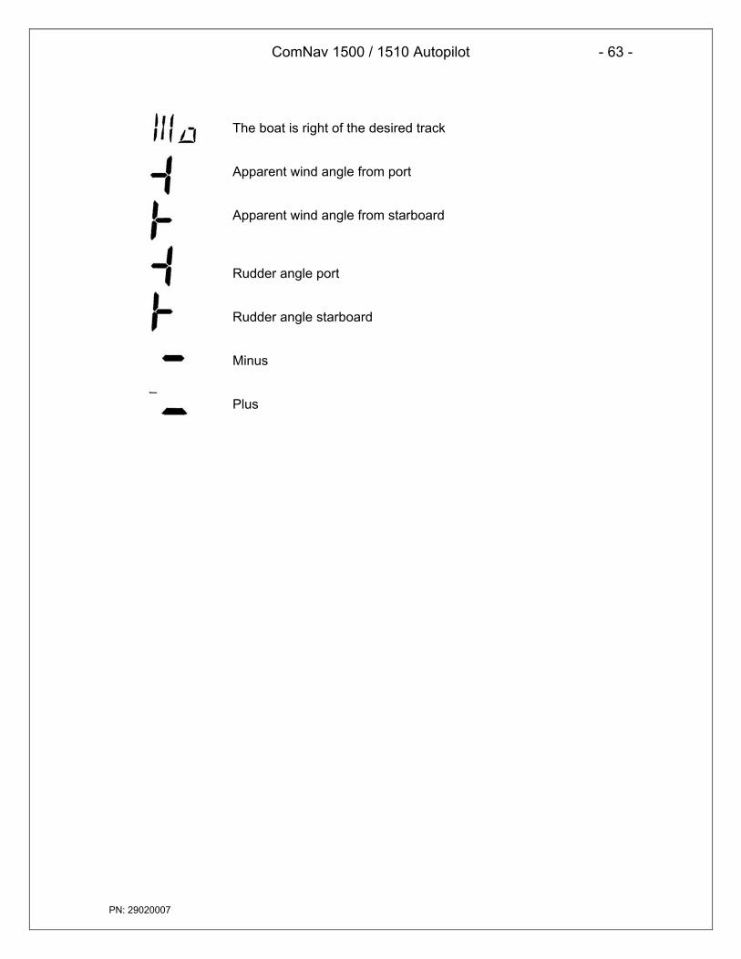
ComNav 1500 / 1510 Autopilot - 63 -
PN: 29020007
The boat is right of the desired track
Apparent wind angle from port
Apparent wind angle from starboard
Rudder angle port
Rudder angle starboard
Minus
Plus