2.77 T-Based Lathe Final Report - Harvard University
23
2.77 T-Based Lathe Final Report Michael Bell | [email protected] May 14 th , 2018 Michael Bell | 2.77 Final Report | 1 | P a g e A video of the final product can be viewed here: https://youtu.be/MwWYYrapAmw Contents Executive Summary ................................................................................................................................................ 2 Requirements of a T-Based lathe ........................................................................................................................... 3 FRDPARRC for T-Based Lathe ............................................................................................................................. 3 Cutting Forces .................................................................................................................................................... 4 Linear Motion Module ............................................................................................................................................ 4 FRDPARRC for Linear Module............................................................................................................................. 4 Design Concepts ................................................................................................................................................. 5 Chosen Design Details ........................................................................................................................................ 6 Screw Hole Spacing Parametrically from Clamping Force Cone ........................................................................ 6 Adjustable keeper plate force ............................................................................................................................ 7 Calculations ........................................................................................................................................................ 7 Yaw, Pitch and Roll ......................................................................................................................................... 8 Friction ........................................................................................................................................................... 8 Stiffness.......................................................................................................................................................... 9 Manufacturing .................................................................................................................................................... 9 Results & Measurements ................................................................................................................................. 10 Geometric Errors.......................................................................................................................................... 10 Stiffness........................................................................................................................................................ 10 Frictional Forces ........................................................................................................................................... 11 Rotary Motion Module ......................................................................................................................................... 11 FRDPARRC for Rotary Module .......................................................................................................................... 12 Manufacturing of the Rotary Module .............................................................................................................. 12 Testing (Instron for stiffness, geometric with simple dial indicator) ............................................................... 13 Dynamic Accuracy / Repeatability .................................................................................................................... 14 Comparing Results to Predictions for the Rotary Module + Linear Module .................................................... 15 Replicated Laminate Base Plate Design ................................................................................................................ 15 System-level Design and Results .......................................................................................................................... 17 Spindle .............................................................................................................................................................. 18 Tool Holder ....................................................................................................................................................... 18 Error Budget ..................................................................................................................................................... 19 Turned Disk Flatness/Shape Analysis ............................................................................................................... 19 Conclusions and Reflections ................................................................................................................................. 21 Appendix ............................................................................................................................................................... 21 Bill of Materials (BOM) ..................................................................................................................................... 21
Transcript of 2.77 T-Based Lathe Final Report - Harvard University

2.77 T-Based Lathe Final Report Michael Bell | [email protected]
May 14th, 2018
Michael Bell | 2.77 Final Report | 1 | P a g e
A video of the final product can be viewed here: https://youtu.be/MwWYYrapAmw
Contents Executive Summary ................................................................................................................................................ 2 Requirements of a T-Based lathe ........................................................................................................................... 3
FRDPARRC for T-Based Lathe ............................................................................................................................. 3 Cutting Forces .................................................................................................................................................... 4
Linear Motion Module ............................................................................................................................................ 4 FRDPARRC for Linear Module............................................................................................................................. 4 Design Concepts ................................................................................................................................................. 5 Chosen Design Details ........................................................................................................................................ 6 Screw Hole Spacing Parametrically from Clamping Force Cone ........................................................................ 6 Adjustable keeper plate force ............................................................................................................................ 7 Calculations ........................................................................................................................................................ 7
Yaw, Pitch and Roll ......................................................................................................................................... 8 Friction ........................................................................................................................................................... 8 Stiffness .......................................................................................................................................................... 9
Manufacturing .................................................................................................................................................... 9 Results & Measurements ................................................................................................................................. 10
Geometric Errors .......................................................................................................................................... 10 Stiffness ........................................................................................................................................................ 10 Frictional Forces ........................................................................................................................................... 11
Rotary Motion Module ......................................................................................................................................... 11 FRDPARRC for Rotary Module .......................................................................................................................... 12 Manufacturing of the Rotary Module .............................................................................................................. 12 Testing (Instron for stiffness, geometric with simple dial indicator) ............................................................... 13 Dynamic Accuracy / Repeatability .................................................................................................................... 14 Comparing Results to Predictions for the Rotary Module + Linear Module .................................................... 15
Replicated Laminate Base Plate Design ................................................................................................................ 15 System-level Design and Results .......................................................................................................................... 17
Spindle .............................................................................................................................................................. 18 Tool Holder ....................................................................................................................................................... 18 Error Budget ..................................................................................................................................................... 19 Turned Disk Flatness/Shape Analysis ............................................................................................................... 19
Conclusions and Reflections ................................................................................................................................. 21 Appendix ............................................................................................................................................................... 21
Bill of Materials (BOM) ..................................................................................................................................... 21

Michael Bell | 2.77 Final Report | 2 | P a g e
Executive Summary Throughout the course a set of modules were designed, manufactured and tested leading up to the
assembly of a fully integrated T-based lathe which is designed to face disks with high precision.
Heavy analysis was performed on the design of modules to predict their performance with regards
to stiffness, geometric and load-induced errors. With the goal of machining the face of a small disk
of aluminum the entire lathe was then designed, analyzed, refined and fabricated.
The linear motion module was designed using a rail CNC’d out of aluminum and a matched carriage
using a Delrin slider, spring steel keeper plates for
downwards force and a machined aluminum carriage top
that allows for easy mounting of a spindle or tool holder.
The aluminum rail also has a keeper plate guide rail that
allows adjustment of the force of the keeper plate for
tuning of the motion stage after fabrication.
The rotary motion module used an off-the-shelf T8 lead
screw with nut and was held in place with a rotary
module plate consisting of two face to face bearings,
some custom washers and an O-ring to provide spring
force in the +X direction. The rotary module allows for
both manual and numerical control of the stage through
the use of a knob mounted at the end of the lead screw or
a stepper motor coupled through the use of an MXL timing belt and associated pulleys.
A tool holder and spindle mount were designed for
the X and Z stage. An off-the-shelf ¼” trim router
from Harbor Freight was selected for cost and
speed, and a spindle mount was CNC’d out of
aluminum to mount the spindle in conjunction with
robust hose clamps. The tool holder was also
machined out of an aluminum block and through the
use of two set screws and a flexure securely held the cutting tool.
A replicated laminate base was fabricated out of
1/32” 304 stainless steel laser cut sheets, with a
1” laser cut structural foam core all bonded with
JB Weld on a precision granite slab in a vacuum
bag under 28 mmHg overnight. Captive nuts and
through-holes inserted and drilled before gluing
allowed the linear module stages to be held
securely through the laminate. The laminate based achieved a flatness of <0.0003”, replicating the
flatness of the granite slab fairly well despite this first attempt at making a replicated laminate.
Figure 1 Linear motion module and rotary motion module assembled.
Figure 2 Tool holder and spindle design.
Figure 3 Replicated laminate base made out of 304 SS plates and structural foam.
Michael Bell | 2.77 Final Report | 3 | P a g e
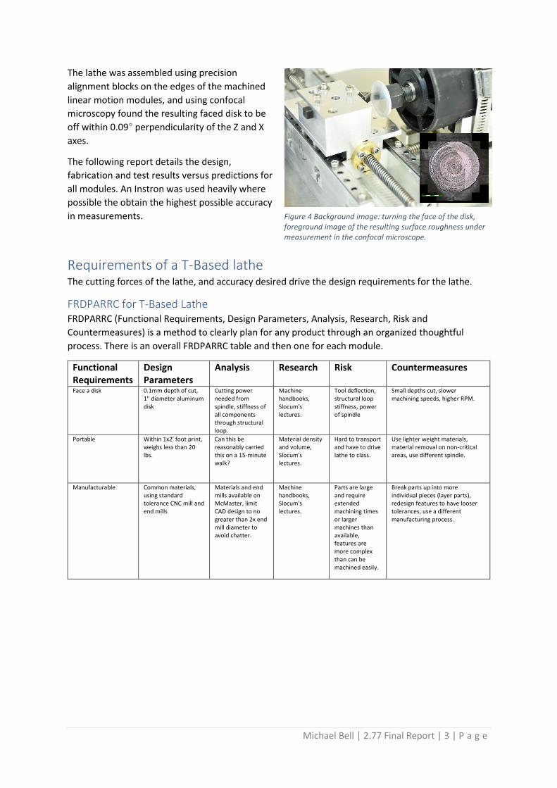
The lathe was assembled using precision
alignment blocks on the edges of the machined
linear motion modules, and using confocal
microscopy found the resulting faced disk to be
off within 0.09° perpendicularity of the Z and X
axes.
The following report details the design,
fabrication and test results versus predictions for
all modules. An Instron was used heavily where
possible the obtain the highest possible accuracy
in measurements.
Requirements of a T-Based lathe The cutting forces of the lathe, and accuracy desired drive the design requirements for the lathe.
FRDPARRC for T-Based Lathe FRDPARRC (Functional Requirements, Design Parameters, Analysis, Research, Risk and
Countermeasures) is a method to clearly plan for any product through an organized thoughtful
process. There is an overall FRDPARRC table and then one for each module.
Functional Requirements
Design Parameters
Analysis Research Risk Countermeasures
Face a disk 0.1mm depth of cut, 1" diameter aluminum disk
Cutting power needed from spindle, stiffness of all components through structural loop.
Machine handbooks, Slocum's lectures.
Tool deflection, structural loop stiffness, power of spindle
Small depths cut, slower machining speeds, higher RPM.
Portable Within 1x2' foot print, weighs less than 20 lbs.
Can this be reasonably carried this on a 15-minute walk?
Material density and volume, Slocum's lectures.
Hard to transport and have to drive lathe to class.
Use lighter weight materials, material removal on non-critical areas, use different spindle.
Manufacturable Common materials, using standard tolerance CNC mill and end mills
Materials and end mills available on McMaster, limit CAD design to no greater than 2x end mill diameter to avoid chatter.
Machine handbooks, Slocum's lectures.
Parts are large and require extended machining times or larger machines than available, features are more complex than can be machined easily.
Break parts up into more individual pieces (layer parts), redesign features to have looser tolerances, use a different manufacturing process.
Figure 4 Background image: turning the face of the disk, foreground image of the resulting surface roughness under measurement in the confocal microscope.

Michael Bell | 2.77 Final Report | 4 | P a g e
Cutting Forces In order to figure out how much force and stiffness my linear
stage is to withstand, I calculated the cutting force on a 1”
diameter aluminum disk.
To calculate the forces, I assumed 30% of my 28,000 RPM (~8,400
RPM through the use of a speed controller), and 0.1mm depth of
cut. The router is ½ hp or around 400 watt, so my cutting power
must be significantly lower than what the router can produce or
it will cause the router to slow down while loaded.
SUMMARY OF CUTTING RESULTS
CUT SPEED, V (M/MIN) 335
CUTTING POWER, P (W) 66
POWER LOAD OF ROUTER (W) 16%
TORQUE (N-M) 0.075
FORCE, TANGENTIAL, FC 11.9
FORCE, THRUST, FT 8.3
The cutting power load of the router is important, as I would like a good factor of safety on this –
which I have of 6x. The forces seen on the stage for both tangential and thrust are within reason,
albeit taking 100um off the face. With these forces in mind, I set off designing a linear and rotary
module to withstand these cutting forces.
Linear Motion Module The linear motion module’s primary purpose is to move a carriage carrying either the spindle or tool
in a single axis as accurately as possible. A FRDPARRC was created to cover all the requirements.
FRDPARRC for Linear Module
Functional Requirements
Design Parameters Analysis Research Risk Countermeasures
Moves in a linear direction Sliding contact
Friction? Lock-up? Accuracy/repeatability?
Look at Slocum's examples.
Look at machine
handbooks
.
Locks up, is not accurate or repeatable.
Modify for better radius, add lubricant.
Transportable for class Ball Bearings Cost? Material use?
Complexity of making ball bearings. Avoid using.
Simple to manufacture Roller Bearings Cost? Material Use?
Complexity of making roller bearings. Avoid using.
Be hand operable (for now) Flexures
Complexity to manufacture?
Hard to analyze with only first order equations. Use existing designs.
Hydrostatic bearings
Cost? External hydraulic source?
Cost, lead-time, complexity. Avoid using.
Wood
Accuracy? Where to machine?
Is not accurate, has to be completely made by hand.
Print out templates to cut wood on bandsaw, sand down by hand to get good surface finish.
Plastic Cost?
Could be laser cut, then the whole thing is sheets of plastic.
Epoxy all sheets together with common base, use scrap material if available.
Figure 5 Relevant dimension for a
tool cutting on a workpiece as
used in the calculations on the
spreadsheet. 1
Michael Bell | 2.77 Final Report | 5 | P a g e
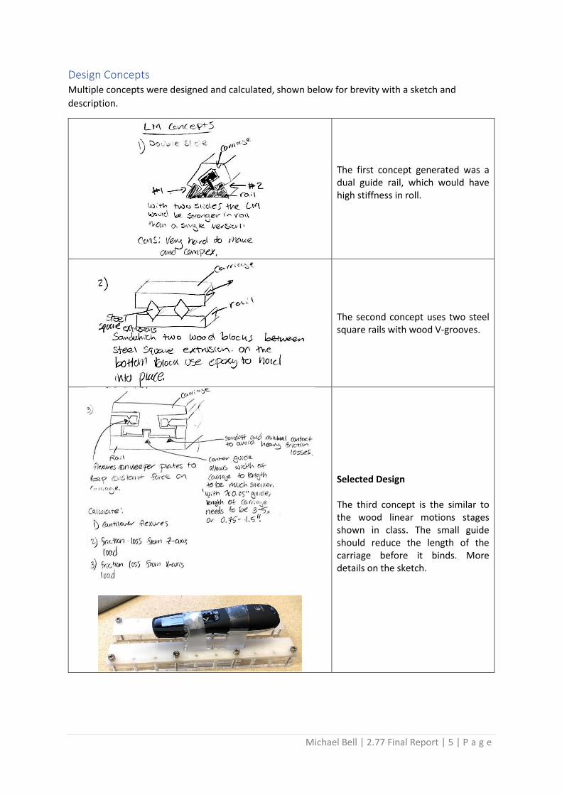
Design Concepts Multiple concepts were designed and calculated, shown below for brevity with a sketch and
description.
The first concept generated was a dual guide rail, which would have high stiffness in roll.
The second concept uses two steel square rails with wood V-grooves.
Selected Design The third concept is the similar to the wood linear motions stages shown in class. The small guide should reduce the length of the carriage before it binds. More details on the sketch.
Michael Bell | 2.77 Final Report | 6 | P a g e
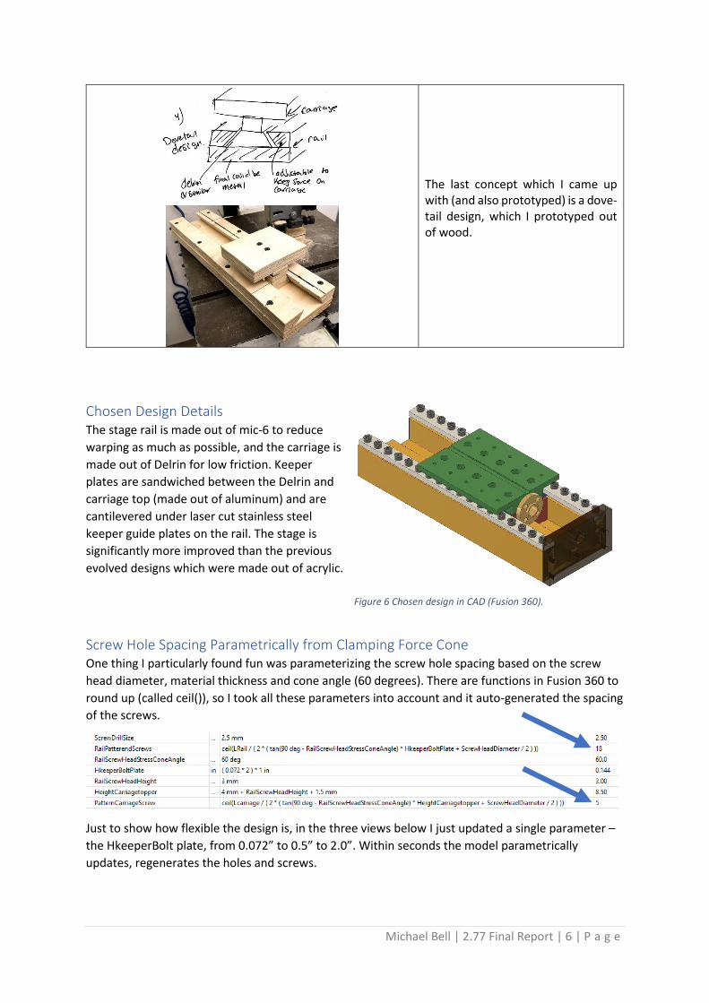
The last concept which I came up with (and also prototyped) is a dove-tail design, which I prototyped out of wood.
Chosen Design Details The stage rail is made out of mic-6 to reduce
warping as much as possible, and the carriage is
made out of Delrin for low friction. Keeper
plates are sandwiched between the Delrin and
carriage top (made out of aluminum) and are
cantilevered under laser cut stainless steel
keeper guide plates on the rail. The stage is
significantly more improved than the previous
evolved designs which were made out of acrylic.
Screw Hole Spacing Parametrically from Clamping Force Cone One thing I particularly found fun was parameterizing the screw hole spacing based on the screw
head diameter, material thickness and cone angle (60 degrees). There are functions in Fusion 360 to
round up (called ceil()), so I took all these parameters into account and it auto-generated the spacing
of the screws.
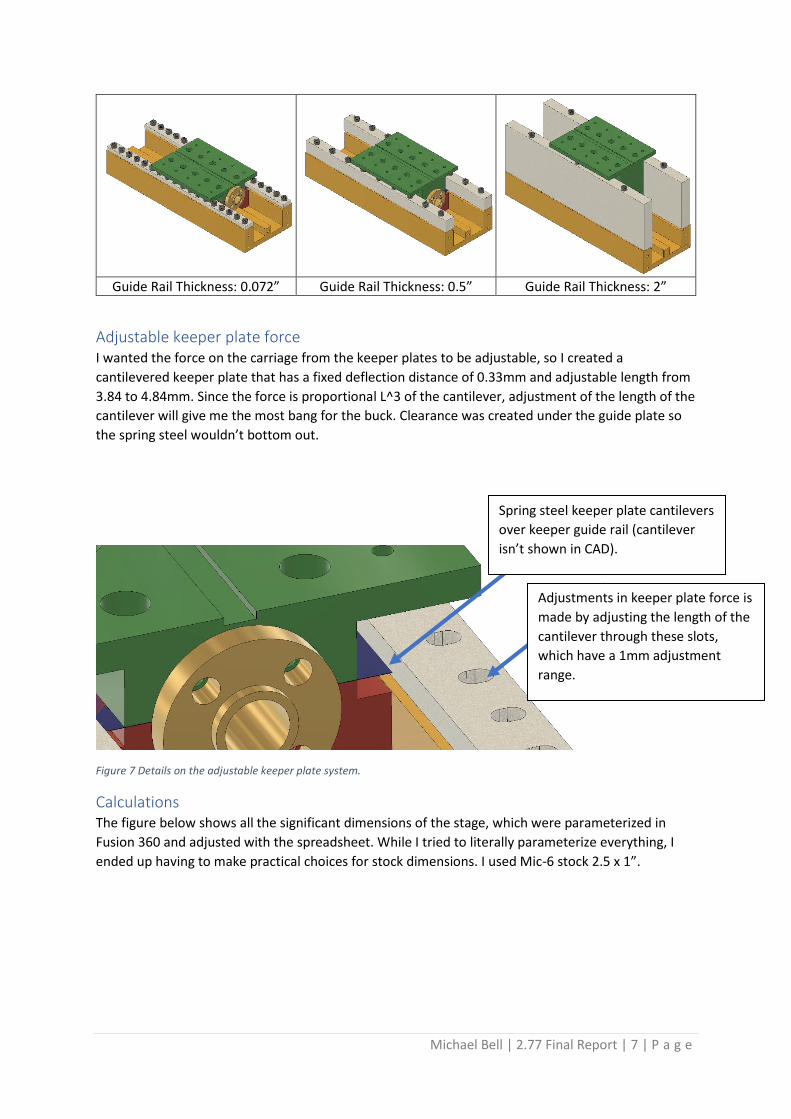
Just to show how flexible the design is, in the three views below I just updated a single parameter –
the HkeeperBolt plate, from 0.072” to 0.5” to 2.0”. Within seconds the model parametrically
updates, regenerates the holes and screws.
Figure 6 Chosen design in CAD (Fusion 360).
Michael Bell | 2.77 Final Report | 7 | P a g e
Guide Rail Thickness: 0.072” Guide Rail Thickness: 0.5” Guide Rail Thickness: 2”
Adjustable keeper plate force I wanted the force on the carriage from the keeper plates to be adjustable, so I created a
cantilevered keeper plate that has a fixed deflection distance of 0.33mm and adjustable length from
3.84 to 4.84mm. Since the force is proportional L^3 of the cantilever, adjustment of the length of the
cantilever will give me the most bang for the buck. Clearance was created under the guide plate so
the spring steel wouldn’t bottom out.
Figure 7 Details on the adjustable keeper plate system.
Calculations The figure below shows all the significant dimensions of the stage, which were parameterized in
Fusion 360 and adjusted with the spreadsheet. While I tried to literally parameterize everything, I
ended up having to make practical choices for stock dimensions. I used Mic-6 stock 2.5 x 1”.
Spring steel keeper plate cantilevers
over keeper guide rail (cantilever
isn’t shown in CAD).
Adjustments in keeper plate force is
made by adjusting the length of the
cantilever through these slots,
which have a 1mm adjustment
range.

Michael Bell | 2.77 Final Report | 8 | P a g e
Figure 8 Key dimensions of the linear motion module.
Yaw, Pitch and Roll Based on the design, the expected yaw pitch and roll are below.
Designed
Yaw (degrees) 0.078
Roll (degrees) 0.655
Pitch (degrees) 0.000
I expect zero pitch errors as the stage is preloaded with the keeper plates. For roll, there are three
types of roll that could occur and the one shown above is the smallest, which comes from the outer
carriage rolling on the outer rail. This was designed so that the center guide rail would not be
responsible for the roll as it could deform the Delrin, and the outer parts of the carriage are much
less critical than the center guide.
Friction Using a coefficient of friction with Delrin on metal of 0.27, the predicted frictional forces are below.
Note that since the guide rail for the keeper plate is adjustable, we’d see a range of forces.
Keeper Plate Downwards Forces w/adjustable range
Keeper Plates Max (N) 219
Keeper Plates Nominal (N) 152
Keeper Plates Min (N) 109
This design updated the keeper plates from 0.002” to 0.010” after finding the 0.002” inadequate in
force. The lead screw has more than enough force to overcome the preload from the keeper plates.
The overcoming forces are from frictional, shown below:

Michael Bell | 2.77 Final Report | 9 | P a g e
Frictional Forces in Z (sliding axis)
u_delrin_on_metal 0.27
F_static (max) (N) 59
F_static (nominal) (N) 41
F_static (min) (N) 30
Stiffness The Y-axis has different stiffnesses for +/- direction. Stiffnesses were based on cutting forces also
calculated. The limiting material for all stiffness is the Delrin, with a modulus of elasticity of 3.3 GPa.
Stiffness
Y+ stiffness from keeper plate (N/mm) 2.00E+02
Y- stiffness from (N/mm) 9.90E+04
X stiffness (N/mm) 1.16E+05
Z stiffness (N/mm) Actuator, rotary module
Yaw Stiffness - (N-mm/rad) 2.53E+08
Pitch Stiffness - (N-mm/rad) 5.16E+09
Manufacturing I made the LM stage through CNCing and laser cutting. Below are a few images from the process.
The guide rail was CNC’d and was nearly the maximum length for the vice I was using. There were 36
total M3 threaded screw holes, which I had fusion automatically generate
based on the 60 degree cone forces from the screw heads and the keeper
guide rail plate thickness. I figured in testing I wouldn’t need all of these
holes since the load from the spring steel was small, but I had the CNC do all
the drilling and tapping so they were essentially free in labor. The rail took
around an hour to CNC.
The Delrin slider for the carriage cut super quick, around 15 minutes for the
3-sided operation (running at 180 in/min feed rate, 9000 RPM 0.5” 2-flute
end mill).
The carriage top was also made out of aluminum and spacing of the screws
was also auto-generated based on the 60 degree cone stress and material
thickness. The carriage top took around 30 minutes to machine, with 3
operations.
Figure 9 Left: Rail base during manufacturing, middle: Delrin slider part of the carriage base, right: top of carriage.
Figure 10 Laser cutting of the keeper rail guide plate out of 1/8" steel.

Michael Bell | 2.77 Final Report | 10 | P a g e
Lastly, the keeper plates (made out of 0.002” spring steel) and the stainless steel keeper guide plates
were both laser cut on a 150W laser. They took a few minutes each to cut.
Results & Measurements I made my yaw, pitch and roll measurements over a 199” distance in my lab’s hallway (while blinding
people who were walking up the stairs). The rail was mounted in a spare vice to make sure the
ground was rigid and fixed. I used a combination of this and a CMM on the CNC to take
measurements.
Geometric Errors The CMM on the CNC is measuring
repeatability. I’m moving the stage
back and forth and landing at a
similar spot, then doing a
measurement with the machine.
Most measurements were taken with
a CMM attachment on the CNC
(recently calibrated to 0.0001” or
2.54 um). Errors were within reason.
Error Summary Designed Manufactured Tested % from manufactured dimensions
Yaw (degrees) 0.078 0.099 0.074 25%
Roll (degrees) 0.655 0.760 0.895 18%
Pitch (degrees) 0.000 0.000 0.000 0%
Accuracy X (mm) 0.010 0.010 0.008 24%
Repeatability X (mm) 0.030 0.030 0.023 24%
Accuracy Y (mm) 0.001 0.001 0.001 15%
Repeatability Y (mm) 0.003 0.003 0.003 15%
Geometric X (mm) 0.051 0.065 0.048 26%
Stiffness I used the CMM in the
Haas to do these
measurements. To the
right is a photo from
measuring the roll
stiffness with a 1kg load.
The probe is measuring
the difference in height between being loaded and unloaded.
The designed, calculated from fabricated measurements and
measured stiffness values are below. I did not have the actuator
in place as of yet to calculate the Z stiffness. My yaw and roll stiffnesses are both lower than
expected most likely due to the testing method, or hertz contact forces that weren’t accounted for
properly.
Figure 11 Measurements on the linear module, left: using the abbe principle to measure errors with a laser, right: using the CMM on the Haas to measure errors.
Figure 12 Stiffness measurements using the Haas probe for displacement.

Michael Bell | 2.77 Final Report | 11 | P a g e
Stiffness Designed Geometric Measured Method
Y+ stiffness from keeper plate (N/mm) 2.00E+02 2.23E+02 1.88E+02 Instron
Y- stiffness from (N/mm) 9.90E+04 1.00E+05 5.22E+04 Instron
X stiffness (N/mm) 1.16E+05 9.57E+04 7.23E+04 Instron
Z stiffness (N/mm) With Rotary Module Calculations
Yaw Stiffness - (N-mm/rad) 2.53E+08 2.50E+08 1.69E+05 CNC CMM & Weight
Pitch Stiffness - (N-mm/rad) 5.16E+09 5.12E+09 Measured with rotary module
Roll Stiffness (N-mm/rad) 5.10E+07 6.44E+07 1.05E+06 CNC CMM & Weight
Frictional Forces I got pretty close on the frictional force measurement, which can change wildly if there is any
lubricant in the linear module. The nominal force for the as-made version was 30, and I measured 24
N using a spring scale.
Frictional Forces Calculated As made Measured
u_delrin_on_metal 0.27 0.27
F_static (max) (N) 59 56
F_static (nominal) (N) 41 46
F_static (min) (N) 30 28 24
Rotary Motion Module The rotary module added the lead screw and bearing design, plus a manual and numerical control
method for controlling the stage. No design ideas are shown here as a lead screw was planned after
choosing the linear motion module.
Below is the final design of the module, showing all the relevant parts and cross section. I have both
a stepper motor and knob for manual movement of the lathe. With the stepper motor isn’t powered
you can freely move the stage by hand.
Figure 13 Cross section of the final rotary module design.

Michael Bell | 2.77 Final Report | 12 | P a g e
FRDPARRC for Rotary Module Functional Requirements
Design Parameters
Analysis Research Risk Countermeasures
Axial Load > 100N
Stepper Motor Measure motor torque with gear ratio
McMaster, PMD Stepper motor spec's, stall torque
Oversize motor
Radial Load > 10N
Radial load > carriage Y-load
Stiffness tests Notes, PMD Carriage takes on more load and deforms more, bearings break
Measure slowly while measuring deflection, check calculations and oversize bearings.
Accuracy Limit wobbling of carriage
Geometric, video, dial indicator
2.70 lectures and PMD Ch 8
Manufacturing tolerances, bearing selection
Add shim or wave washers to take up any manufacturing errors
Stiffness Materials Geometric 2.70, PMD Wrong material, manufacturing errors
Material selection and verification
Speed / Thermal Slow moving stage
Speed needed to face material
2.70, PMD Heat from friction, higher speed
Better lead screw nut, material selection
Manufacturing Time
5 hours or less CAM modeling Available stock in shop, time estimates from Fusion 360's CAM
Can't make in time, contains manufacturing errors when made
Multiple machines or materials to make parts out of
Manufacturing of the Rotary Module I CNC’d the mounting plate for the stepper motor and lead screw. I used a probe system for
alignment and drilled or bored all precision holes from one side to avoid misalignment. The 0.375”
hole for the bearings came in at 0.3755” using precision gauge pins.
I had some issues with cutting down the T8 lead screw,
especially using the die. I originally wanted to use a
threading tool to make it, but my stick out from the collet
was almost 2” and posed problems with a point contact.
Since the screw did not need to be highly concentric, I used
a die. For some reason, the thread that was formed came
out blunt and jagged in some places. Despite this, the 10-32
thread functioned and I improved this processes on the
second lead screw. I held the die in the tool collet and put
the lead screw in the drill chuck (since I didn’t have the
proper mounting for the die on the tail stock).
Figure 14 Left: Backside of the CNC'd rotary module mounting block, right: front side of block.
Figure 15 Threading 10-32 on the end of the turned down T8 lead screw.
Michael Bell | 2.77 Final Report | 13 | P a g e
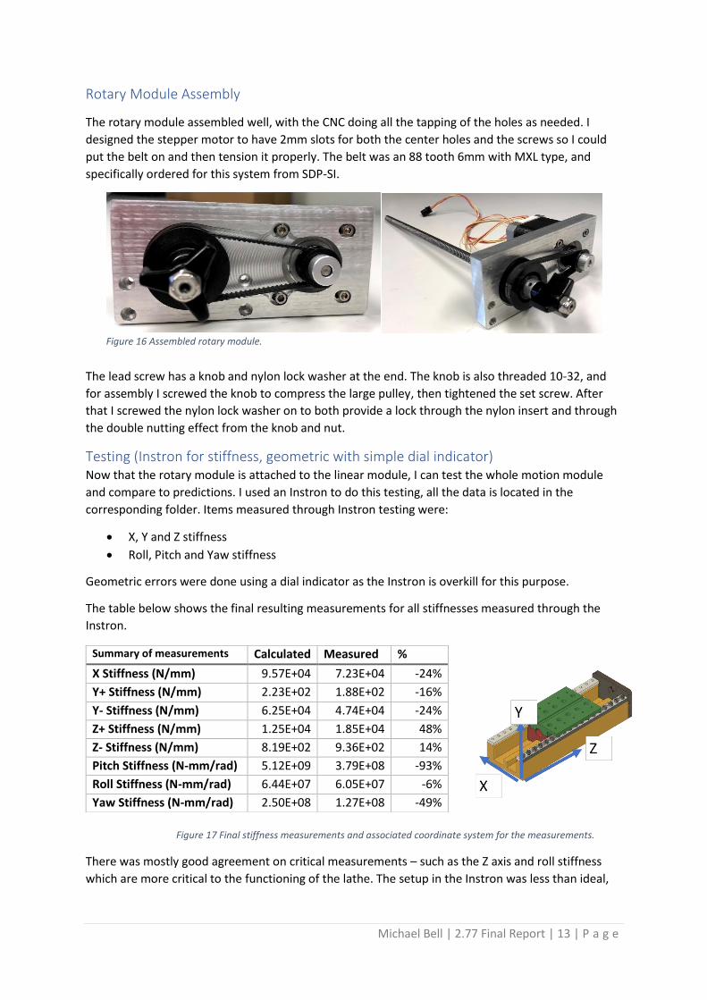
Rotary Module Assembly
The rotary module assembled well, with the CNC doing all the tapping of the holes as needed. I
designed the stepper motor to have 2mm slots for both the center holes and the screws so I could
put the belt on and then tension it properly. The belt was an 88 tooth 6mm with MXL type, and
specifically ordered for this system from SDP-SI.
The lead screw has a knob and nylon lock washer at the end. The knob is also threaded 10-32, and
for assembly I screwed the knob to compress the large pulley, then tightened the set screw. After
that I screwed the nylon lock washer on to both provide a lock through the nylon insert and through
the double nutting effect from the knob and nut.
Testing (Instron for stiffness, geometric with simple dial indicator) Now that the rotary module is attached to the linear module, I can test the whole motion module
and compare to predictions. I used an Instron to do this testing, all the data is located in the
corresponding folder. Items measured through Instron testing were:
• X, Y and Z stiffness
• Roll, Pitch and Yaw stiffness
Geometric errors were done using a dial indicator as the Instron is overkill for this purpose.
The table below shows the final resulting measurements for all stiffnesses measured through the
Instron.
There was mostly good agreement on critical measurements – such as the Z axis and roll stiffness
which are more critical to the functioning of the lathe. The setup in the Instron was less than ideal,
Summary of measurements Calculated Measured %
X Stiffness (N/mm) 9.57E+04 7.23E+04 -24%
Y+ Stiffness (N/mm) 2.23E+02 1.88E+02 -16%
Y- Stiffness (N/mm) 6.25E+04 4.74E+04 -24%
Z+ Stiffness (N/mm) 1.25E+04 1.85E+04 48%
Z- Stiffness (N/mm) 8.19E+02 9.36E+02 14%
Pitch Stiffness (N-mm/rad) 5.12E+09 3.79E+08 -93%
Roll Stiffness (N-mm/rad) 6.44E+07 6.05E+07 -6%
Yaw Stiffness (N-mm/rad) 2.50E+08 1.27E+08 -49%
Figure 16 Assembled rotary module.
Figure 17 Final stiffness measurements and associated coordinate system for the measurements.
Michael Bell | 2.77 Final Report | 14 | P a g e
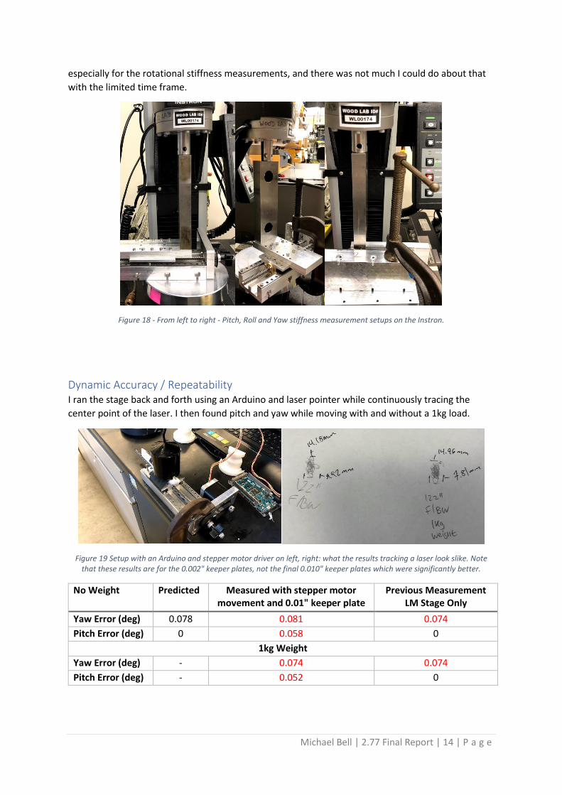
especially for the rotational stiffness measurements, and there was not much I could do about that
with the limited time frame.
Figure 18 - From left to right - Pitch, Roll and Yaw stiffness measurement setups on the Instron.
Dynamic Accuracy / Repeatability I ran the stage back and forth using an Arduino and laser pointer while continuously tracing the
center point of the laser. I then found pitch and yaw while moving with and without a 1kg load.
Figure 19 Setup with an Arduino and stepper motor driver on left, right: what the results tracking a laser look slike. Note that these results are for the 0.002" keeper plates, not the final 0.010" keeper plates which were significantly better.
No Weight Predicted Measured with stepper motor movement and 0.01" keeper plate
Previous Measurement LM Stage Only
Yaw Error (deg) 0.078 0.081 0.074
Pitch Error (deg) 0 0.058 0
1kg Weight
Yaw Error (deg) - 0.074 0.074
Pitch Error (deg) - 0.052 0

Michael Bell | 2.77 Final Report | 15 | P a g e
Comparing the yaw results from previous measurements without the rotary module line up well,
including the predicted values all within 5%. The pitch error is 0.06 degrees more than the prediction
of 0 and is most likely error in my hand measurement trying to trace the center of an 8mm diameter
laser beam at 122 inches distance. In any case, this is well within reason as calculated and designed
for the T-base lathe.
While the stage was designed for numerical control, that portion of the stage is not complete and
thus the stage will be moved by hand for any turned parts.
Comparing Results to Predictions for the Rotary Module + Linear Module My stiffness calculations follow well with predictions. The X stiffness is within 25%, Y+ within 16%
and Y- within 24%. The Y- stiffness calculations were revisited when my Instron testing showed
significant deviation, and I looped back and calculated the stiffness through the various materials
(Delrin, spring steel, aluminum AND the screws) more rigorously.
The Z+ measurement also took a good amount of study, and after accounting for the screws got
below 50% agreement with measurements. I had initially suspected the bearing ball diameter was a
cause for concern, using what Prof. Slocum suggested of 0.060” balls. After tearing apart a bearing I
measured them in at 0.062”, so he was spot on. I then Instron tested the bearing directly and found
it within 5% of what I calculated, so that is not the cause of my error. My last thoughts on this are
that the lead screw is eventually touching my bearing cap plate after some loading, and that the
stiffness is increasing at that point.
The Z- direction agrees nicely with a 14% error. I measured the silicone O-ring directly as getting the
modulus of elasticity from the shore durometer isn’t the most accurate, but in this case, they
matched fairly well.
Pitch, roll and yaw stiffness were within 90%, 6% and 50% respectively. My measuring method for
these as seen in the previous section was not so great, and I’m convinced that the Instron’s stiffness
was a factor in angular stiffness errors. Pitch was likely off also due to the calculations of the nut and
lead screw, which may have been calculated higher than seen.
Overall, I’m was very pleased with the final results of my linear and rotary motion module marriage,
and calculations match within reason to the Instron testing.
Replicated Laminate Base Plate Design The original base was planned to be a simple 0.25” sheet of 6061 Aluminum. Using the laminate
design sheet, the EI for such a plate would be 673 N-m2. With the laminate, as describe below, the EI
is 25,000 N-m2 or 37x that of the aluminum slab!
The base plate of the machine was made using a laminate consisting of 1/32” 304 stainless steel on
top and bottom with a 1” structural foam core. Captive nuts were put on the bottom stainless steel
sheet in two orientations – one for the thru screws holding the linear modules on the top, and one
for holding the 5x rubber feet. The orientation matters greatly so the nuts do not pull through.

Michael Bell | 2.77 Final Report | 16 | P a g e
Figure 20 Cutting of the laminate, left: laser cutting the 304 SS, middle: laser cutting the 1” thick foam, right: stack up showing the draft angle of the foam.
The steel and foam were both cut on a high-powered laser. The foam was tricky to cut as it melts
easily and causes a good amount of draft angle during the process. To compensate, I added ¼”
margin on all sides to the foam perimeter, and during lamination I aligned the top and bottom with
knives that easily penetrated the foam and touch the top and bottom metal.
Figure 21 Process of gluing and aligning the laminate layers. Left: spread of JB Weld over the foam surface, middle: vacuum bag with memory foam on top to make sure the captive nuts create even force over the surface, right: side view of the stack
up under vacuum.
The lamination process as seen in Figure 2 consisted of spreading JB Weld over the top and bottom
of the foam and aligning the sheet metal. This was all done on a granite block 12x18” (the actual
laminate structure is 11x17” to make it easy to use standard imperial sized granite slabs). Memory
foam was added to the top of the laminate, which happens to be the bottom with all the captive
nuts placed in. The top of the laminate was in contact with the granite slab with a very thin plastic
sheet to avoid getting any spilled epoxy stuck to the granite. A thick zip lock bag was placed around
the slab and laminate, and butyl adhesive tape was used around the vacuum hose that was placed
within the bag.
The vacuum was turned on to ~28 mmHg, creating approximately 450 N (101 lbf) of force evenly
spread over the top surface, and left for 16+ hours. Epoxy was expected to get into the holes, and it
did. To get the epoxy house I drilled 2.5mm into the M3 tapped holes, then tapped the threads with
an M3 to clear the clogged threads. Lastly, I lightly sanded the top surface to remove any
imperfections and sanded the foam edges down until they were flush with the stainless steel. Figure
3 shows these steps.
Michael Bell | 2.77 Final Report | 17 | P a g e
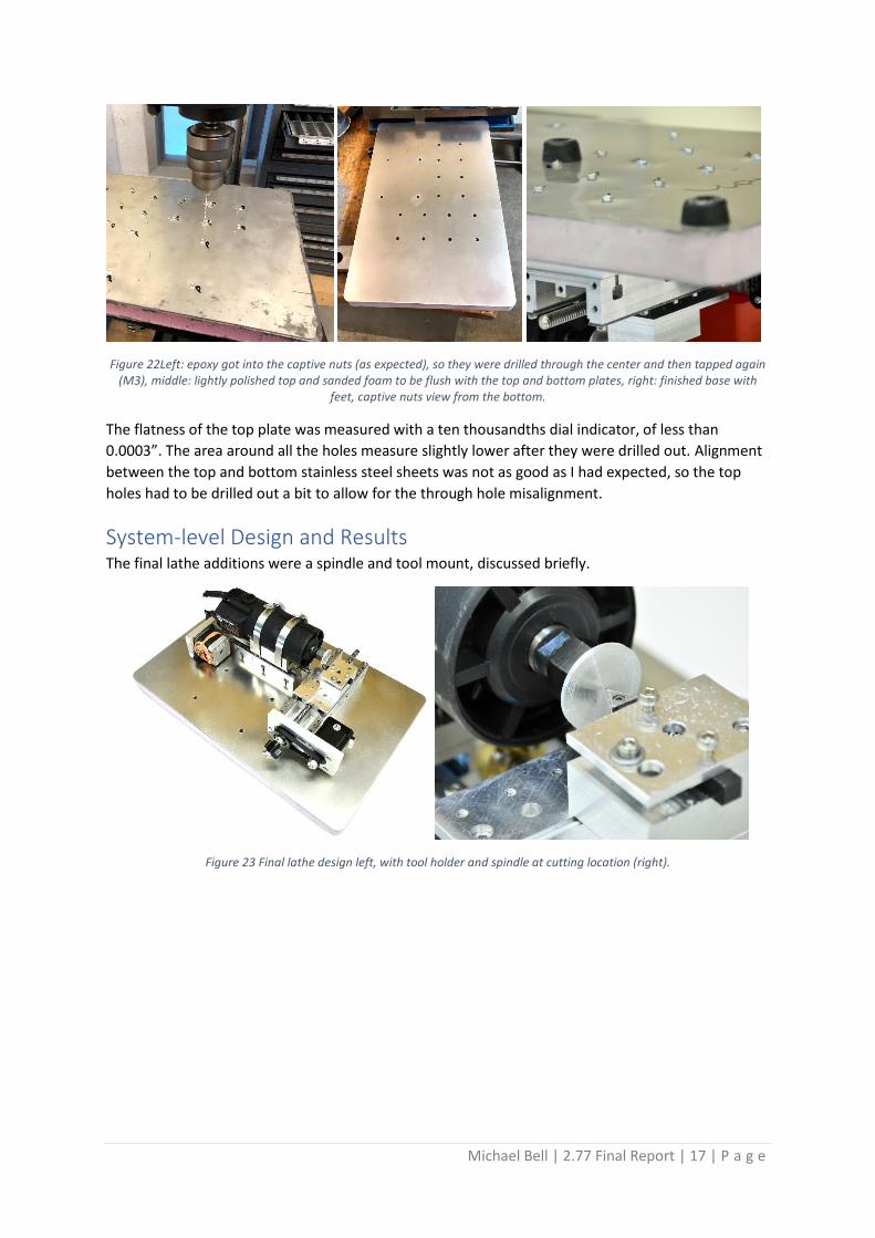
Figure 22Left: epoxy got into the captive nuts (as expected), so they were drilled through the center and then tapped again (M3), middle: lightly polished top and sanded foam to be flush with the top and bottom plates, right: finished base with
feet, captive nuts view from the bottom.
The flatness of the top plate was measured with a ten thousandths dial indicator, of less than
0.0003”. The area around all the holes measure slightly lower after they were drilled out. Alignment
between the top and bottom stainless steel sheets was not as good as I had expected, so the top
holes had to be drilled out a bit to allow for the through hole misalignment.
System-level Design and Results The final lathe additions were a spindle and tool mount, discussed briefly.
Figure 23 Final lathe design left, with tool holder and spindle at cutting location (right).

Michael Bell | 2.77 Final Report | 18 | P a g e
Spindle
Figure 24 front view (left) and iso view of spindle (middle) and final spindle mounted (right).
The spindle is an off-the-shelf ¼” trim router from Harbor Freight, which was a reasonable $24.99. It
is ½ HP and 28,000 RPM so I used a router speed controller to bring the speed to around 30% of the
desired value – 8,400 RPM. The spindle was mounted on a CNC’d spindle mounting plate that
employed a ball end mill to create an exact 2.5” curvature. 3-4” hose clamps were used to hold
down the spindle in the final position. The center of mass was found and thus mounted in the center
of the carriage. There is a moment arm created by the stick out of the spindle, and that is considered
in the full error budget. The final aluminum disk piece was turned from a 1” stock down to 0.25” so it
could fit in the collet.
Tool Holder
Figure 25 ISO view of tool holder with tool (left), front view of tool mounting (middle) and fabricated tool holder (right).
The tool holder was designed so that all downwards cutting force is done within the skid plate area
to avoid any moment put on the carriage. The tool holder sits 2mm within the perimeter of the skid
plate area to avoid this. The height of the tool was large enough to accommodate 1.5” diameter
stock. The tool itself is a ¼” square tool with an insert bit, also purchased at Harbor Freight and was
$29.99 – more expensive than the spindle! The tool is held into the CNC’d tool holder against a flat
area, then a flexure and two set screws are used to hold the tool into place. The flexure makes sure
the tool is pushed against the flat and also pushed downwards.
While a full analysis of the tool holder was outside the scope of the project, I did want to compare
the measured stiffness to that of the components leading up to it. Through an Instron test directly
on the tool tip, the stiffness was measured at 2.21E4 N/mm – which is around a 50% reduction in the
carriage stiffness alone. With cutting load this would be only a 0.5um tool deflection and is very
acceptable.
Michael Bell | 2.77 Final Report | 19 | P a g e
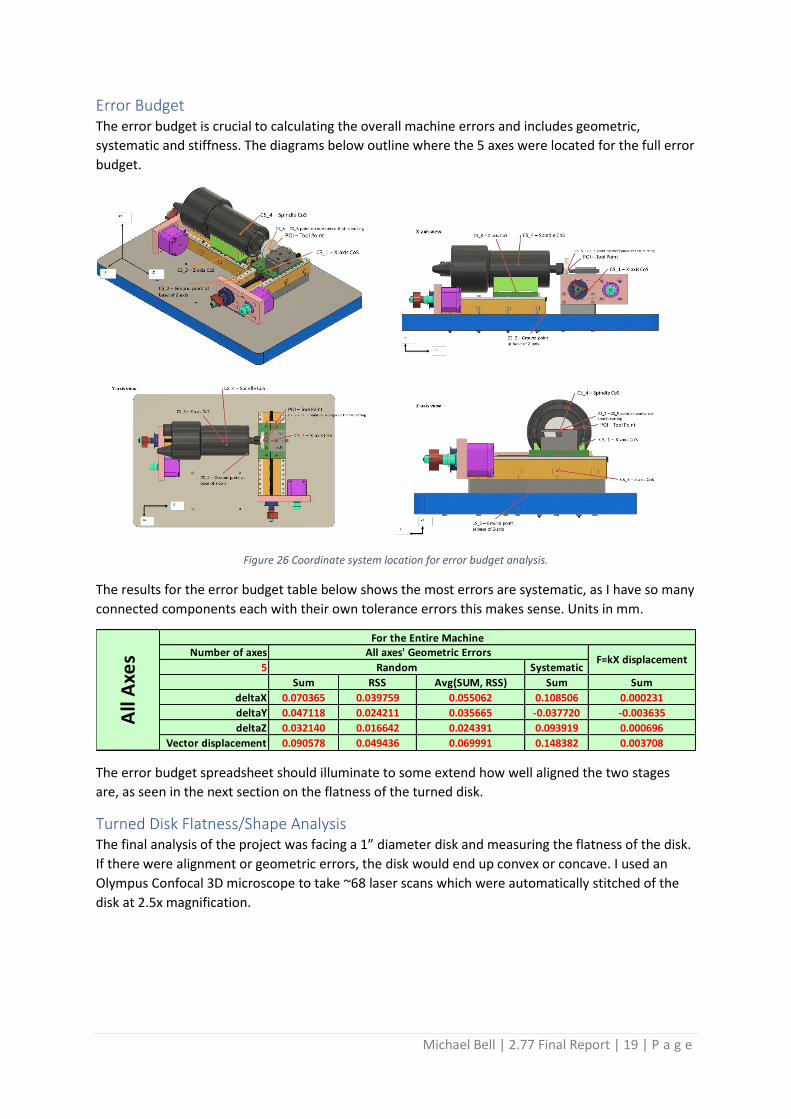
Error Budget The error budget is crucial to calculating the overall machine errors and includes geometric,
systematic and stiffness. The diagrams below outline where the 5 axes were located for the full error
budget.
Figure 26 Coordinate system location for error budget analysis.
The results for the error budget table below shows the most errors are systematic, as I have so many
connected components each with their own tolerance errors this makes sense. Units in mm.
The error budget spreadsheet should illuminate to some extend how well aligned the two stages
are, as seen in the next section on the flatness of the turned disk.
Turned Disk Flatness/Shape Analysis The final analysis of the project was facing a 1” diameter disk and measuring the flatness of the disk.
If there were alignment or geometric errors, the disk would end up convex or concave. I used an
Olympus Confocal 3D microscope to take ~68 laser scans which were automatically stitched of the
disk at 2.5x magnification.
Number of axes
5 Systematic
Sum RSS Avg(SUM, RSS) Sum Sum
deltaX 0.070365 0.039759 0.055062 0.108506 0.000231
deltaY 0.047118 0.024211 0.035665 -0.037720 -0.003635
deltaZ 0.032140 0.016642 0.024391 0.093919 0.000696
Vector displacement 0.090578 0.049436 0.069991 0.148382 0.003708
F=kX displacement
All
Axe
s
For the Entire Machine
All axes' Geometric Errors
Random

Michael Bell | 2.77 Final Report | 20 | P a g e
Figure 27 Left: stitched image of the disk surface as seen from the confocal microscope, right: 3D view of the disk with a plane showing the area of measurement.
After microscope correction of the tilt of the disk on the platform, I analyzed the resulting data to
see how misaligned the Z and X stages are. An angle >90 degrees between the two stages during
operation would cause the disk to be concave, while less than 90 degrees would cause it to be
convex.
Figure 28 Surface measurement of the disk directly from the confocal microscope. The Y-axis spans a large range, but the trend initially shows no cup or dome-like shape. Units are in um.
I took an output of this data and zoomed in on the Y-axis which isn’t very well shown in the figure
above. The zoomed in image below shows more surface roughness. I removed the data from the
center of the faced disk and used a linear line fit on the right and left sides mirroring the center.
Figure 29 Plotted data from the confocal on the flatness of the cross section through the center. No measurable misalignment was seen.
The data in the plot above demonstrates how well aligned the two stages are. The surface roughness
is <10um, and a trendline fit to the left and right sides of the data independently show a slope
difference of 3E-5 and 6E-5, both in the positive direction. Normalizing for the mean of these slopes

Michael Bell | 2.77 Final Report | 21 | P a g e
with 4.5E-5, I would see a -1.5E-5 and +1.5E-5 for left and right sides respectively, leading to slightly
concave shape.
However, difference in the slopes is well below the noise of the data so without a finer surface finish
(and thus less roughness) of the disk I wouldn’t be able to make any assumptions other than they are
well aligned to 20um at the end of the disk or less than +/-0.09 degrees between the Z and X stage.
Pretty darn good!
Conclusions and Reflections The lathe faces a disk at the calculated depth and speed, after nine weeks of work! All the systems
didn’t come together until a week prior to the final report – not that they weren’t done, I just was
busy testing all individual components on the Instron like crazy because my calculations and
predictions were off by ~10x (see more below). The fact that it went together on the first try, turned,
and agrees with predictions is a testament to the upfront work in design, fabrication and testing.
I’m very satisfied with my final stiffness measurements which were all updated since the modules
were due. I was nearly 6x off on a few of them during week 10 but went back and calculated
element by element including cross sections that were changing throughout the Y-axis. I also found
that my Instron data has been off by nearly 10x throughout the course, and after talking to Prof.
Slocum was able to correct that, bringing data within reason.
Although not required for the lathe, I didn’t have time to implement the kinematic coupling or
elastic average coupling content we learned in the beginning of the course. For a future teaching of
this course, I would have liked to design the lathe first, then implement those modules as a tool
holder or method to align other features of the lathe. There is no seeming reason not to have
couplings taught in week 5.
This course has been one of the most challenging and exciting that I’ve taken in graduate school. The
overwhelming at times amount of work in design and fabrication really pushed my bounds and I
especially expanded my skills in design analysis of structures and the use of spreadsheets to make
clear calculations that are all parametrically driven. I started the semester without a concrete shop
or machine to make my components, but after five weeks of overhauling a Haas office mill was able
to exclusively use that machine throughout the remaining nine weeks to manufacture and refine my
parts. While I feel like I only really absorbed a fraction of the course content, I know exactly what I
don’t fully remember and where to find the spreadsheets and relevant equations for use in my own
research and industry.
Appendix
Drawings Drawings are located external to this document.
Bill of Materials (BOM) Category Part# QTY Description
Hardware H14 8 M3x30mm SS socket head cap screws for Y-axis mounting to base
Hardware H15 8 M3x50mm SS socket head cap screws for X-axis mounting to base
Hardware H16 2 M3x6mm SS socket head cap screws for lathe bit set screws
Hardware H10 1 M3x18mm SS socket head cap screws for lathe tool mount

Michael Bell | 2.77 Final Report | 22 | P a g e
Hardware H17 2 M3x30mm SS socket head cap screws for lathe tool mount
Custom Standoff CS1 1 Custom standoff block for X-axis, 16x59x172mm
Spindle S1 1 Drill Master trim router Harbor Freight #62659
Spindle Mount SM1 1 Spindle mounting adapter, machined, AL 6061, 26x64x75 mm
Tool Mount TM1 1 Tool mount for lathe bit, machined, AL 6061, 34x45x26 mm
Cutting Tool CT1 1 Indexable mini lathe set 5 pieces harbor freight #39931
Speed Controller SC1 1 Router speed control dial harbor freight #43060
Rotary and Linear Module RLM 2 Fully assembled rotary and linear module sub-assemblies
Laminate Base LB 1 Laminate mounting base sub-assembly
LB - Laminate Mounting Base Sub-assembly
Laminate Top L1 1 11x17 laser cut SS304 1/32" sheet for top of laminate
Laminate Bottom L2 1 11x17 laser cut SS304 1/32" sheet for bottom of laminate
Laminate Core L3 1 11.25x17.25 laser cut structural foam 1" for core
Adhesive A1 1 10oz tube JB Weld 8265-S
Hardware H11 24 Zinc-plated steel press-fit nut for sheet metal, 1mm thickness, McMaster 99437A130
Hardware H12 5 Rubber Bumper with Unthreaded Hole McMaster 9540K914
Hardware H13 5 M3x16mm SS socket head cap screws (for bumpers)
RLM - Rotary and Linear Module Sub-assembly
Carriage C01 1 Carriage base, CNC, acetal Delrin, 37.1x75x19.95mm
Carriage C02 1 Carriage top, CNC, Mic-6, 75x59.3x11.61mm
Carriage C03 2 Keeper Plate, Laser Cut, spring steel, 0.010"x75x15.14mm
Linear Rail R01 1 Rail Base, CNC, Mic-6, 175x59.3x25mm
Linear Rail R02 2 Keeper Guide Plate, Laser Cut, SS 304 1/16"x10x175mm
Pulley P1 1 MXL 88 tooth Belt - SDP-SI A 6Z16M088060
Pulley P2 1 MXL Pulley 21 tooth - SDP-SI A 6T16M021DF6005
Belt B1 1 MXL 88 tooth Belt - SDP-SI A 6Z16M088060
Hardware H1 1 Manual Handle - McMaster 57715K22
Hardware H2 1 M5 Nylon Lock Nut - McMaster 91831A411
Hardware H3 1 M5 Standard Washer - McMaster 92141A011
Hardware H4 1 Square O-ring (spring) - McMaster 1182N01
Hardware H5 2 2x Bearing 3/16” ID - McMaster 57155K373
Hardware H6 4 M3x 8mm SS socket head cap screws (for stepper motor)
Hardware H7 3 M3x10mm SS socket head cap screws (for cap plate)
Hardware H8 5 M3x15mm SS socket head cap screws (for RM to LM plate)
Hardware H9 46 M3 10mm length screws
Hardware H10 10 M3x18mm screws to hold cartridge to delrin slider
Custom Hardware CH1 1 Spacer - AL 1/16” thickness, 0.259” OD, 0.189” ID
Custom Hardware CH2 1 Spacer - AL 0.01” thickness, 0.259” OD, 0.189” ID
Custom Hardware CH3 1 Spacer - 0.01” thickness, 0.375” OD, 0.303” ID
Custom Hardware CH4 1 Spacer - 0.01” thickness, 0.375” OD, 0.224” ID
Custom Hardware CH5 1 Cap Plate - AL 6061, Custom part
Custom Hardware CH6 1 T8 Lead Screw - SS 304, Custom Part

Michael Bell | 2.77 Final Report | 23 | P a g e
Mounting Plate MP1 1 RM Plate 1 - AL 6061
Electronics E1 1 NEMA 17 Stepper Motor