27535-01A 542 '06tanning-bed-parts.com/documents/ETS Tan... · 27535-01A ii elcome Congratulations...
36
27535-01A
Transcript of 27535-01A 542 '06tanning-bed-parts.com/documents/ETS Tan... · 27535-01A ii elcome Congratulations...
27535-01A

27535-01A
i
STANDARD 48 MONTH WARRANTY
Your ETS Distributor (including ETS, Inc. if purchased directly), through a manufacturer’s warranty, warrantsyour tanning unit to be free of structural defects in material and workmanship, under normal use, for its lifetime.Your ETS Distributor will, at its discretion, repair any structural defect which materially affects the performanceof the tanning unit, or replace the tanning unit.
For forty-eight (48) months following the shipping date of your tanning unit, your ETS Distributor will providereplacements for parts that prove to be defective in material or workmanship. Fluorescent lamps, and lamp startersare warranted against manufacturer’s defects for a period of ninety (90) days following the shipping date of yourtanning unit. Acrylics will be warranted against manufacturer’s defects for a period of 2 years (prorated).
Labor costs associated with repair or replacement work covered by this warranty will be reimbursed for repair orreplacement work required to be performed for a period of one (1) year following the shipping date of your tan-ning unit. Normal wear and tear, damage from misuse or abuse, damage incurred in transit or damages resultingfrom unauthorized repairs or modifications are not covered by this warranty. Warranty coverage does not includecosmetic abnormalities such as scratches, nicks, dents, or other cosmetic changes that do not materially interferewith the function of the tanning unit.
THIS STANDARD 48 MONTH WARRANTY IS EXPRESSLY MADE IN LIEU OF ANY OTHER WARRANTIES,EXPRESS OR IMPLIED, INCLUDING ANY IMPLIED WARRANTIES OF MERCHANTABILITY AND FITNESSFOR A PARTICULAR PURPOSE, WHICH ARE HEREBY DISCLAIMED. No one has the authority to change ormodify this Standard 48 Month Warranty in any respect. To obtain service under this Standard 48 MonthWarranty, contact your authorized ETS Distributor (or ETS, Inc. if purchased directly). Proof of purchase, includ-ing serial number, is required.
IN NO EVENT SHALL YOUR DISTRIBUTOR OR THE MANUFACTURER BE LIABLE AT LAW OR IN EQUI-TY FOR ANY LOSS, LIABILITY, DAMAGE OR EXPENSE IN AN AMOUNT IN EXCESS OF THE PURCHASEPRICE RECEIVED, OR FOR LOSS OF USE OR PROFITS, LOSS OF TIME, INCONVENIENCE, RENTAL ORSUBSTITUTE PRODUCTS, LOSS OF BUSINESS, LOSS OF INCOME, OR ANY OTHER INCIDENTAL, INDI-RECT, SPECIAL OR CONSEQUENTIAL DAMAGES. Some states do not allow the exclusion or limitation ofincidental or consequential damages, and the above limitation or exclusion will not apply to residents of somestates. This Standard 48 Month Warranty gives you specific, legal rights and you may have other rights which mayvary from state to state.
All warranty service must be performed by an authorized service person. All labor charges must be authorized byyour ETS Distributor prior to the start of repairs and must not exceed the established rates and time allotmentpolicies established by your ETS Distributor. If your tanning unit must be returned for service, all freight chargesshall be at your expense. Contact your ETS Distributor for the authorized Service Center nearest you. This war-ranty is serial number specific and only applies to tanning units purchased through an authorized ETS Distributor.This warranty is extended to the individual or legal entity whose name appears on the original sales document andmay not be transferred to any other individual or legal entity. This warranty is void if the tanning unit is modifiedin any manner from its original design.
To obtain warranty service, contact your place of purchase. Proof of purchase, including serial num-ber, is required for verification. Contact ETS, Inc. only if you purchased your equipment directly.
ETS, Inc. 7445 Company Drive, Indianapolis, IN 46237-92961-800-449-3605 In Canada call 1-800-661-6292 or 519-421-1212

2753
5-01
A ii
elcomeCongratulations on your purchase of this technologically advanced sun tanning unit. It has beendesigned to provide years of dependable service for you.
Please read all the instructions in this booklet before installing and using the unit. Always be sure toobserve all safety precautions.
ontentsSafety Information . . . . . . . . . . . . . . . . . . . . . . . . . . . . . . . . . . . . . . . .iii
Installation . . . . . . . . . . . . . . . . . . . . . . . . . . . . . . . . . . . . . . . . . . . . . .1Unpacking and Inspection . . . . . . . . . . . . . . . . . . . . . . . . . . . . . .1Tools Required . . . . . . . . . . . . . . . . . . . . . . . . . . . . . . . . . . . . . .1Pre-Installation Planning . . . . . . . . . . . . . . . . . . . . . . . . . . . . . . .2Hardware Inventory . . . . . . . . . . . . . . . . . . . . . . . . . . . . . . . . . . .3Assembly Procedures . . . . . . . . . . . . . . . . . . . . . . . . . . . . . . . . . .4Electrical Connections . . . . . . . . . . . . . . . . . . . . . . . . . . . . . . . . .9Final Adjustments . . . . . . . . . . . . . . . . . . . . . . . . . . . . . . . . . . .10Remote Connections . . . . . . . . . . . . . . . . . . . . . . . . . . . . . . . . .11
Operation . . . . . . . . . . . . . . . . . . . . . . . . . . . . . . . . . . . . . . . . . . . . .16Before You Tan . . . . . . . . . . . . . . . . . . . . . . . . . . . . . . . . . . . . . .16Exposure Times . . . . . . . . . . . . . . . . . . . . . . . . . . . . . . . . . . . . .16Using Your Sunbed . . . . . . . . . . . . . . . . . . . . . . . . . . . . . . . . . .17
Care and Maintenance . . . . . . . . . . . . . . . . . . . . . . . . . . . . . . . . . . . .19Cleaning After Use . . . . . . . . . . . . . . . . . . . . . . . . . . . . . . . . . . .19Thorough Periodic Cleaning . . . . . . . . . . . . . . . . . . . . . . . . . . . .19Mechanical Inspection . . . . . . . . . . . . . . . . . . . . . . . . . . . . . . . .19Lamp and Acrylic Replacement . . . . . . . . . . . . . . . . . . . . . . . . .20
Troubleshooting . . . . . . . . . . . . . . . . . . . . . . . . . . . . . . . . . . . . . . . . .24

Ultraviolet radiation. Follow instructions. Avoid overexposure. As with natural sunlight, overexposure can causeeye and skin injury and allergic reactions. Repeated exposure may cause premature aging of the skin and skin
cancer. WEAR PROTECTIVE EYEWEAR; FAILURE TO MAY RESULT IN SEVERE BURNS OR LONGTERM INJURY TO THE EYES.Medications or cosmetics may increase your sensitivity to the ultraviolet radiation. Consult physician before using sunlamp if you areusing medications or have a history of skin problems or believe yourself especially sensitive to sunlight. If you do not tan in the sun, youare unlikely to tan from the use of this product. Children, the elderly, or fair skinned people who always burn easily and either never tanor tan minimally should not use this equipment.
To use, lie down under canopy and pull down as far as adjustment will allow maintaining at least 3 inches (7.6 centimeters) between yourbody and canopy clear plastic panel, otherwise overexposure may occur. Minimum use distance elsewhere is touching the clear plasticpanels. Do not use without clear plastic panels in place. Untanned persons should not tan on consecutive days during their first week oftanning. Never tan more than once a day. Tanning normally appears after the first few sessions and maximizes after approximately fourweeks. Tan once or twice per week thereafter to maintain appearance. Persons already having a base tan may begin at advanced levelscorresponding to the extent of their base tan.
New lamps emit approximately 10% more ultraviolet radiation during the first 50 hours of operation. Recommended tanning times shouldtherefore be reduced by approximately 10% during that period.
WARNING: • Read the instructions booklet before using this sunlamp product. • All persons in the room should wear protective eyewearwhen lamps are on. Recommended eyewear: provided eyeshields or equivalent eyewear as defined under 21 CFR 1040.20. Other typesof eyewear may not provide adequate protection. Failure to use protective eyewear may result in severe burns or other eye injury. If dis-comfort develops, discontinue use and consult a physician.
ONLY THE FOLLOWING LAMPS HAVE BEEN CERTIFIED FOR USE IN THE 542:BRONZING SUN™ PLUS Wolff® Model BSP 71-T12-100WR BI-PIN (Bench lamps)
Velocity® VS-R™ Wolff® Model VEL71-T12-160W VS-R Bi-Pin (Canopy lamps)
Heraeus E400 HPT -or- Philips Model HPA 400/30s -or- CosmoTech Model 23045 (SolarMax™ IFT facial unit)
THIS EQUIPMENT MUST BE EARTH GROUNDED.
This product is in conformity with performance standards for sun lamp products under 21 CFR PART 1040.20 andANSI/UL Standard 482. Certified to CAN/CSA Standard C22.2 NO. 224.
27535-01A
iii
afety InformationLABELING NOTICE: Labels are affixed on all systems to inform the user of possible dangers. Regulations are stated in 21 CFR, Section1040.20, and require that all products manufactured after September 8, 1986 which use sunlamps must display the following:
88465
DISCONNECT POWER BEFORE ATTEMPTING TO CLEAN, RELAMP, OR ENGAGE IN THE MAINTENANCE OF THIS PRODUCT.
DANGER
RECOMMENDED EXPOSURE TIMES IN MINUTES MAXIMUM EXPOSURE TIME IS 12 MINUTESLevel 1/Week 1
Level 2 Level 3 Level 4Subsequent
Skin Type: 1st-3rd Sessions Maximum
I Sensitive Skin (Burns easily and severely and does not tan.) NOT RECOMMENDED FOR TANNINGII Light (Burns easily and severely and tans minimally.) 2 4 7 10 12III Normal (Burns moderately and tans average.) 3 6 9 12 12IV Dark (Burns minimally, tans easily and above average.) 4 7 10 12 12

Rayonnement ultraviolet. Veuillez suivre les instructions. Évitez une exposition excessive. Tout comme pour lesrayons du soleil, une exposition excessive peut causer des blessures aux yeux et à la peau et provoquer des réac-
tions allergiques. Une exposition répétée peut causer le vieillissement prématuré de la peau et provoquer le cancer de la peau. PORTEZDES LUNETTES PROTECTRICES: LE NON-RESPECT DE CETTE CONSIGNE DE SÉCURITÉ PEUT ENTRAÎNER DE GRAVESBRÛLURES OU DES LÉSIONS OCULAIRES À LONG TERME. Les médicaments ou les produits cosmétiques peuvent augmenter votresensibilité au rayonnement ultraviolet. Consultez un médecin avant d’utiliser la lampe solaire si vous prenez des médicaments, si voussouffrez d’une maladie cutanée ou si vous croyez être particulièrement sensible aux rayons du soleil. Si vous ne bronzez pas au soleil, ilest peu probable que vous bronzerez sous une lampe solaire. Les enfants, les personnes âgées et les personnes qui ont une peau clairequi brûle facilement, ne bronze jamais ou alors très peu, ne devraient pas utiliser cette lampe.
Étendez-vous sous la partie supérieure, puis abaissez celle-ci aussi bas que possible, en veillant cependant à conserver un espaced’au moins 3 pouces (7,60 centimètres) entre le corps et le panneau de plastique transparent de la partie supérieure, afin d’éviter uneexposition excessive. Les autres parties du corps peuvent toucher les panneaux de plastique transparents. N’utilisez pas la lampesans les panneaux de plastique transparents. La première semaine de bronzage, les personnes qui n’ont pas un hâle initial ne doiventpas se faire bronzer tous les jours. Ne vous faites jamais bronzer plus d’une fois par jour. Le bronzage commence normalement àapparaître après les premières séances : il atteint son apogée au bout d’environ quatre semaines. Les personnes qui ont déjà unteint hâlé peuvent commencer à des niveaux plus élevés, selon l’importance de leur hâle initial.
Les lampes neuves émettent approximativement 10 % de plus de rayons ultraviolets au cours des 50 premières heures de fonction-nement. Le temps de bronzage doit donc êatre réduit d’environ 10 % pendant cette période.
AVERTISSEMENT : • Lisez le livret d’instructions avant d’utiliser cette lampe solaire. • Les autres personnes présentes dans la piècedoivent aussi porter des lunettes protectrices lorsque les lampes sont allumées. Coquilles de protection pour les yeux recommandées: Lescoquilles de protection fournies ou l’équivalent, tel que le stipule le document 21 CFR 1040.20. Les autres types de lunettes protectricespeuvent ne pas assurer une protection adéquate. Utilisé sans lunettes protectrices, ce produit peut causer des brûlures ou lésions oculairesgraves. Si vous souffrez d’un malaise, arrêtez l’utilisation et consultez un médecin.
SEULES LES LAMPES SUIVANTES ONT ÉTÉ HOMOLOGUÉES POUR CET ÉQUIPEMENT :BRONZING SUN™ PLUS Wolff® Modèle BSP 71-T12-100WR BI-PIN (banc seulement)
Velocity® VS-R™ Wolff® Modèle VEL71-T12-160W VS-R Bi-Pin (partie supérieure seulement)
Heraeus E400 HPT -ou- Philips Modèle HPA 400/30s -ou- CosmoTech Modèle 23045 (unité faciale)
Cet équipement doit être mis à la terre.
Ce produit est conforme aux normes de rendement pour les lampes solaires dans le documents 21 CFR, partie1040.20 , ANSI/UL 482 , CAN/CSA C22.2 N° 224.
TEMPS D’EXPOSITION RECOMMANDÉ EN MINUTES LE TEMPS D’EXPOSITION MAXIMAL EST DE 12 MINUTESÉlevé 1/Semaine 1
Élevé 2 Élevé 3 Élevé 4Sem. suivantes
Type de peau: 1ere
-3e Temps maximal
I Peau sensible (brûle facilement et ne bronze pas) NON RECOMMANDÉII Peau claire (brûle facilement et bronze très peu) 2 4 7 10 12III Peau normale (brûle et bronze de façon modérée) 3 6 9 12 12IV Peau foncée (brûle très peu, bronze plus facilement que la moyenne) 4 7 10 12 12
2753
5-01
A iv
Renseignements sur la Sécurité
88465
Débrancher l’alimentation électrique avant de nettoyer l’appareil , d’en faire l’entretien ou de changer les lampes.
DANGER

27535-01A
1
nstallation
Unpacking and Inspection
The bench and canopy are each wrappedin plastic. Pull back the plastic and, witha helper, grasp the canopy and pull it fromthe carton bottom, leaving the plasticwrap and the carton packaging. Do thesame for the bench. Do not attempt to lifteither unit with the plastic still on as itmay slip. Do not lift the canopy by itsplastic endcaps. The ballast tray is securedto the carton bottom with brackets.Remove these brackets from the ballasttray with a Phillips screwdriver.
Note! The cartons are reusable. You maywish to save them for future use.
After unpacking the unit, check to makesure you have received the following:
• Canopy unit• Bench unit• Ballast tray• Metal access panel• Long metal hinge cover panel• Two large endcaps• Body fan (in a box)• Bag containing necessary assembly
hardware, safety goggles, and pillow.
Inspect these items, including the canopyand bench, to make sure they are freefrom any visible damage. Report theextent of any damage to the transportationcompany.
Record the serial number of the unit in thearea provided at the back of this manual.This information will be required whenev-er you call customer service.
Tools RequiredYou will need the following tools toassemble your sunbed.
#2 Phillips Screwdriver
Adjustable Wrench
9/16” Wrench
5/16” Allen Wrench
(included in the hardware kit)

2753
5-01
A 2
Installation - Pre-Installation Planning
Pre-Installation PlanningBefore you begin to assemble your sunbed, you should observe the following consid-erations.
• The SOLARIS® 542 operates from a220V AC power source. The unitshould be wired to a dedicated cir-cuit capable of providing 50 Ampservice. This unit must be hardwireddirectly to a junction box. We rec-ommend connection by a profes-sional electrician.
• IMPORTANT! Voltage must bebelow 230V AC or may require aBuck Booster.
WARNINGShock hazard.Disconnect power beforeservicing.
Air from the room is used to coolthe sunbed. Maximum ambientroom temperature should be 80°F.Place your sunbed no closer than6” from any wall. Make sure nothingobstructs the airflow into thesunbed’s endcaps or out of the fanopenings. A poorly ventilated roommay cause the unit to become hotand cause discomfort to the user.
CAUTION
Use of a voltage source above 230VAC may prevent proper operation ofthe sunbed and could cause damageand void the warranty.
CAUTION
Proper assembly of your sunbedrequires three people. Plan to havea couple of helpers assist you.
CAUTION

27535-01A
3
Installation - Hardware Inventory
Hardware Inventory
Open the hardware bag and remove thecontents. In addition to a pillow, the Allenwrench and an RJ-11 (phone type) cable,make sure you have the following hard-ware items.
Safety GogglesQuantity 1
Access Panel KeyQuantity 1
#10 x 1” PhillipsPan Head Screw
Quantity 14
3/8-16 x 1 1/4”Hex Socket Bolt
Quantity 6
3/8-16 Self-lockingHex Nut
Quantity 6
#10 x 1/2” PhillipsPan Head Screw
Quantity 4
WARNINGWear protective eyewear.Failure to may result in severe burns orlongterm injury to the eyes.

2753
5-01
A 4
Installation - Assembly Procedures
Assembly Procedures
Before installing the foot end endcap youmust install the body fan power cord intothe endcap, as shown below. The connec-tor will snap securely into the endcap. Thebody fan kit includes instructions forinstallation.
BODY FAN POWER CORD
Snap body fan powercord into hole in footend endcap.

27535-01A
5
Installation - Assembly Procedures
Parts needed:Head end endcapFoot end endcap14 - #10 x 1” Phillips pan-head screws4 - #10 x 1/2” Phillips pan-head screws
Attach each endcapwith 7 - 1” screwsas shown.
Foot end endcapshown.
Use 1/2” screws here.
2753
5-01
A 6
Installation - Assembly Procedures
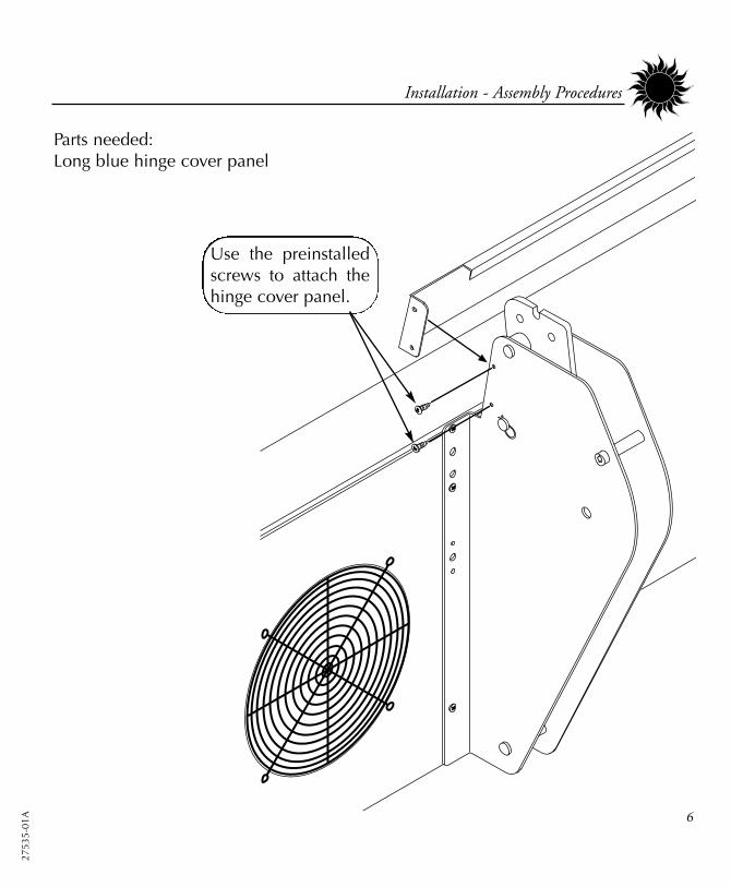
Use the preinstalledscrews to attach thehinge cover panel.
Parts needed:Long blue hinge cover panel

27535-01A
7
Installation - Assembly Procedures
CANOPY ARM
HINGE ARM
Install this bolt as apositioning aide.
Slip canopy arm onto hingearm. Positioning bolt willengage the slot on top ofhinge arm and hold canopyup while the other bolts areinstalled.
Install other bolts asshown. Secure all sixbolts in place with self-locking nuts.
Parts needed:6 - 3/8 x 1 1/4” hex-socket bolts6 - 3/8” self-locking hex nuts
Remove this pinand discard.
1
2
3
4

2753
5-01
A 8
Installation - Assembly Procedures
Slide ballast trayunder and pull cordsthrough to the back.
Put access panel inplace and lock withaccess panel key.
Install Body Fan.Instructions areincluded in BodyFan kit.

27535-01A
9
Installation - Electrical Connections
Electrical ConnectionsAt the rear of the sunbed, connect the twocanopy power cords and two bench powercords from the ballast tray to their respectivepower receptacles. Simply match the plugto the receptacle, push on firmly and secureby twisting the threaded locking ring.Connect the RJ-11 (phone type) cablebetween the canopy and rear jack on theballast drawer. The three jacks on the frontof the drawer are for remote connections.Connect main power cord as described inPre-Installation Planning.
PIN CONFIGURATIONS MAY VARY FROM SHOWN
(Rear of ballast tray shown)
Helpful Hint: Line up the plug with theproper receptacle and push in. Applypressure to the plug and twist the lockingring counter-clockwise until you feel theplug click into place. Then turn the lock-ing ring clockwise to secure it. The ringwill click when fully engaged.

2753
5-01
A 10
Installation - Final Adjustments
LIFT ADJUSTMENT
MAINTENANCE HEIGHT RELEASE HANDLEAIR FILTERS
Final Adjustments
Your sunbed uses a smooth gliding springlift system to raise the canopy. This lift sys-tem may need to be adjusted slightly dueto shipment. Remove the front accesspanel. Use a wrench to turn the hexshaped Lift Adjustment lugs (shownbelow), clockwise for more lift and coun-terclockwise for less. When adjustedproperly, the canopy should raise easily aswell as rest fully closed. Always adjustboth lugs equally.
Make sure the air filters are in place. Thefilter on top of the ballast tray simply sitsover the vent holes. Airflow holds it inplace when the unit is on. The airflowarrow on the side of this filter should pointdown. The filter hanging under the benchshould be installed with the arrow point-ing up.
LIFT ADJUSTMENT

27535-01A
11
Installation - Remote Connections
Remote Connections
Your sunbed incorporates advanced cir-cuitry allowing it to connect and commu-nicate with most remote control systems.If a remote system is to be used, firstdetermine whether the remote system is aT-Max® System or a standard remote sys-tem operating with a control relay. Thefollowing pages outline many differentremote connection scenarios. Find thescenario that best fits your application.
Three remote ports are located on top ofthe ballast drawer at the front, two RJ-22(4-wire) ports and one RJ-11 (6-wire)port. A Remote Control Bypass plug isalready installed in one of the RJ-22remote control ports. Your sunbed will notoperate without the Remote Control Bypassplug or a remote system connected.
ATTENTION: Although the RemoteControl Bypass plug provided with yoursunbed will work wherever a T-Max® ter-minator is called for in the series, the T-Max® terminator will not work as abypass plug. Normally, a bypass plug isneeded only when your sunbed is operat-ed without a remote system connected.
You will notice some wire clamps alongthe side of the fan housing under thebench. These are for the remote cables tokeep them out from under the ballastdrawer when rolling the drawer in andout of the unit. Route the remote cablesas shown below, leaving some slack forthe drawer to roll out.
REAR
TO REMOTEPORT
FAN HOUSING UNDER BENCH
REMOTE PORTS
WIREDREMOTE
PORTS (RJ-22)
WIRELESSREMOTE
PORT (RJ-11)

2753
5-01
A 12
Installation - Remote Connections
CAUTIONThe remote connection is not designed to supplyor accept high voltage, nor can it provide powerto an external timer. The sunbed’s remote inter-face circuitry operates on 5 volts, attempting toconnect it to any higher voltages will damage thesunbed as well as void your warranty.
Remote Connections
Your sunbed incorporates advanced circuitryallowing it to connect and communicate withmost remote control systems. If a remote sys-tem is to be used, first determine whether theremote system is a T-Max® System or a stan-dard remote system operating with a controlrelay. Follow the appropriate instructions foryour system type.
T-Max® ProductsThe T-Max® remote systems offer the ultimatein sunbed control, while allowing the tannereasy straightforward operation. Your sunbed isconfigured to directly connect to this system,including the new wireless remote system.The circuitry inside your sunbed eliminatesthe need for the T-Max® 1A or 3A when con-necting to the T-Max® Manager series. Yoursunbed supports the auto addressing featureof the latest T-Max® Manager models and thefollowing parameters: 5, 6, 7, 8, 9, 10, 15 and23. See your T-Max® manual for descriptionsof these parameters and how they function.
REMOTE PORTS
WIREDREMOTE
PORTS (RJ-22)
WIRELESSREMOTE
PORT (RJ-11)
T-Max® Wireless Remote System The T-Max® AP-900 eliminates wires in yoursalon, allowing easy setup without hiring anelectrician to run wires. It also protects yourinvestment from damage by isolating eachunit from one another. Your sunbed arrives“wireless ready”, which means it connectsdirectly to the T-Max® wireless system.
The T-Max® wireless system is available intwo configurations: AP-900 Retail and AP-900OEM. The Retail version contains a poweradapter which plugs into a standard 110Voutlet. The OEM version gets power from thetanning bed through the same RJ-11 cable ituses to communicate, eliminating the needfor an outlet. Tanning beds labelled “wirelessready” use the AP-900 OEM.
Remote System Hook-up ScenariosFollow the diagrams on the next page to seethe many different scenarios for hooking upyour salon. If you need further assistance, callT-Max® directly at (417) 338-5101.

27535-01A
13
Installation - Remote Connections
Scenario 1 - T-Max® Manager Series with wiresThis system is ideal for multiple sunbed installa-tions. Simply connect the RJ-22 modularcable(s), described in the T-Max®Manager manual, into the remote port(s)located on the ballast drawer and follow theinstructions that came with your remote system.If you have an older T-Max® Manager that doesnot support auto addressing, set the address ofeach sunbed manually as described in Settingthe address manually. You can place yoursunbed at any location in the series.
Scenario 2 - Single Bed wired to T-Max® 3AIn single sunbed installations, the T-Max® 1A and3A can offer the same control as the T-Max®Manager, eliminating the need for a Manager. Ifyou’re using a 1A in this manner, it must have achip labelled “master” installed on its circuitboard. The remote control bypass plug must not beused in this configuration. The 3A may be used asa “master” with no modification.
NOTE: A T-Max® 1A with a“master” chip can be substituted
for a 3A.
Scenario 3 - T-Max® ManagerSeries with Complete WirelessConnect one AP-900 Retail to theManager and one AP-900 OEMto each of the tanning beds.Install as many beds as you likewith this configuration. Units thatdo not communicate with T-Maxwill need an AP-900 Retail andan additional 3A to operate.
After you have set the T-Max® 1A’s, or 3A’s, addressto “0” (refer to your T-Max® user’s guide) and thesunbed’s address to “1”, simply connect the RJ-22modular cables, described in the T-Max® user’sguide, directly into either of the smaller ports locat-ed on the ballast drawer and either port on theback of the T-Max® 1A or 3A.
2753
5-01
A 14
Installation - Remote Connections
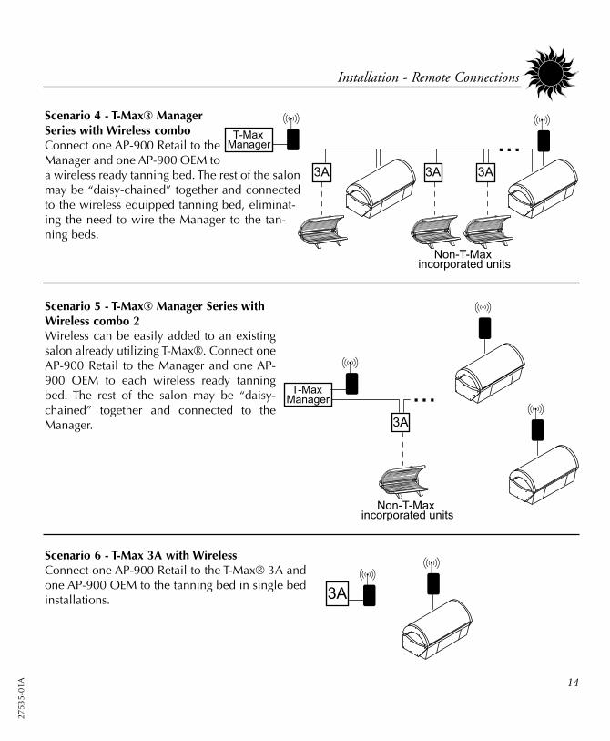
Scenario 4 - T-Max® ManagerSeries with Wireless comboConnect one AP-900 Retail to theManager and one AP-900 OEM toa wireless ready tanning bed. The rest of the salonmay be “daisy-chained” together and connectedto the wireless equipped tanning bed, eliminat-ing the need to wire the Manager to the tan-ning beds.
Scenario 5 - T-Max® Manager Series withWireless combo 2Wireless can be easily added to an existingsalon already utilizing T-Max®. Connect oneAP-900 Retail to the Manager and one AP-900 OEM to each wireless ready tanningbed. The rest of the salon may be “daisy-chained” together and connected to theManager.
Scenario 6 - T-Max 3A with WirelessConnect one AP-900 Retail to the T-Max® 3A andone AP-900 OEM to the tanning bed in single bedinstallations.

27535-01A
15
Installation - Remote Connections
CAUTIONThe remote connection is not designed to supplyor accept high voltage, nor can it provide powerto an external timer. The sunbed’s remote inter-face circuitry operates on 5 volts, attempting toconnect it to any higher voltages will damage thesunbed as well as void your warranty.
Scenario 7 - Non T-Max® Remote System wiredto unitMost non-T-Max® remote systems control thesunbed by the use of a relay. The relay operatesthe sunbed by connecting and disconnecting apair of wires leading from the sunbed. Refer to theuser’s manual provided with your remote systemto determine if it operates in this way. To connectyour sunbed to this type of system a remote inter-face kit is required. Contact your place of purchaseto obtain the kit. The illustration below details atypical connection. Follow the instructions provid-ed with the kit and from the remote’s manual tomake the necessary connections.
Setting the sunbed address manuallyBefore connecting your sunbed to the T-Max®Manager or T-Max® 1A or 3A, the address ofyour sunbed must first be set. Set the “id” man-ually as described below.
Setting the “id” 1. Make sure no cables are plugged into
your sunbed’s remote ports.2. Remove and reapply power to the unit.3. Press and hold the stop button, located
on the sunbed display, for three secondsand release. The display should indicatean “id” number from “oF” to “252”.
4. If you are using a T-Max® 1A or 3A as a“master” remote, the “id” of the sunbedmust be set to “1”. If you are using a T-Max® Manager each sunbed must beassigned a different “id”. To set the “id”press the timer button, to count up, orthe body fan control button, to countdown, until the desired number isachieved.
5. Press the stop button to return to thenormal display mode.
1-99
100-199
200-252

2753
5-01
A 16
peration
Before You Tan
Before using your sunbed, please note thefollowing important precautions.
• Your skin should be free of cosmetics,oils, or other body lotions prior to tan-ning except for those specificallymade for use with tanning devices.However, do not remove natural bodyoils by bathing or showering immedi-ately before tanning.
• Your hair should be free of gels,mousses, sprays, or other hair productsprior to tanning. These products cancause damage to the sunbed acrylic.As an alternative, a shower cap ortowel can be worn to keep treated hairaway from the sunbed surfaces.
• This unit intended for individual use.Only one pair of eyewear is included.
Exposure Times
Follow the guidelines for skin type andexposure times as shown in the tablebelow. Untanned persons should not tanon consecutive days during their first weekof tanning. Never tan more than once aday. Tanning normally appears after the firstfew sessions and maximizes after approxi-mately four weeks. Tan once or twice perweek thereafter to maintain appearance.Persons already having a base tan maybegin at advanced levels corresponding tothe extent of their base tan.
DANGERShock hazard.
Do not operate this device nearwater or while you are wet.
DANGERSome medication may increase your sensi-tivity to ultraviolet light. It is recommendedthat you consult a physician before usingthis sunbed if taking any medication or if yoususpect that your skin might be especiallysensitive to sunlight.
RECOMMENDED EXPOSURE TIMES IN MINUTES MAXIMUM EXPOSURE TIME IS 12 MINUTESLevel 1/Week 1
Level 2 Level 3 Level 4Subsequent
Skin Type: 1st-3rd Sessions Maximum
I Sensitive Skin (Burns easily and severely and does not tan.) NOT RECOMMENDED FOR TANNINGII Light (Burns easily and severely and tans minimally.) 2 4 7 10 12III Normal (Burns moderately and tans average.) 3 6 9 12 12IV Dark (Burns minimally, tans easily and above average.) 4 7 10 12 12

27535-01A
17
Operation - Using Your Sunbed
1. Lift canopy, lie down on bench (face up),lower canopy toward your body usingcanopy handle. For best results, positioncanopy as close to your body as possible.
2. Put on your safety goggles.
3. Assuming the remote system has been setto allow a pre-tanning delay time, the timerdisplay (D) will repeatedly flash the delaysymbol “dL” and then the remaining delaytime. Press the timer button (F) or wait untilthe delay time has expired to begin the tan-ning session. The lamps will turn on andthe timer will begin to count down.
4. When the timer reaches 0 the lamps turn off.If you want to interrupt your session beforetime expires, press the stop button (E).
5. Raise the canopy by using the canopyhandle, do not push up on the acrylicshield. The cooling fans run for a period oftime after the lamps shut off to aid in cool-ing the sunbed. The timer will indicate “..”as a reminder to clean the sunbed. Afterthe sunbed is cleaned press the timer but-ton and the display will return to “0”.
Using Your SunbedWhen connected to the T-Max® Manager or T-Max® 1A or 3A.
A Face tanner control - Turns face tannerson and off during use. Face tannerlamps require one minute to relight.
B Body fan control - Controls the speed ofthe body fan during use.
C Body fan speed indicator - Indicatesspeed of fan. (OFF - LOW - MED -HIGH)
D Timer display - Displays remaining time.
E Stop button - Interrupts tanning session.
F Timer button - Turns bed on. Timer dis-play shows remaining time.
A B C D E F
WARNINGWear protective eyewear.Failure to may result in severe burns orlongterm injury to the eyes.

2753
5-01
A 18
Operation - Using Your Sunbed
Using Your SunbedWhen used as a stand alone unit or when connected to a remote system using a control relay.
1. Lift the canopy, lie down on the bench(face up), lower the canopy toward yourbody using the canopy handle. For bestresults, position the canopy as close toyour body as possible.
2. Put on your safety goggles.
3. Press the timer button (F) to begin the tan-ning session. The lamps will turn on andthe timer will begin to count down.
4. If a tanning time less than the displayedtime is desired repeatedly press the timerbutton (F) to decrease the remaining time.
5. When the timer reaches 0 the lamps turnoff. If you want to stop your session beforetime expires, press the stop button (E). Youwill have ten seconds to restart with theremaining time, otherwise the timer willreset to 0.
6. Raise the canopy by using the canopyhandle, do not push up on the acrylicshield. The cooling fans run for a period oftime after the lamps shut off to aid in cool-ing the sunbed.
A B C D E F
A Face tanner control - Turns face tannerson and off during use. Face tannerlamps require one minute to relight.
B Body fan control - Controls the speed ofthe body fan during use.
C Body fan speed indicator - Indicatesspeed of fan. (OFF - LOW - MED -HIGH)
D Timer display - Displays remaining time.
E Stop button - Stops tanning session.
F Timer button - Turns bed on. Timer dis-play shows remaining time. If a lessertime is desired, press timer button untildesired time is displayed.
WARNINGWear protective eyewear.Failure to may result in severe burns orlongterm injury to the eyes.

27535-01A
19
are and Maintenance
Cleaning After Use
Clean and disinfect your tanning bed’sbench and canopy after each use. Use anon-abrasive disinfectant cleaner that doesnot contain ammonia or ammonia deriva-tives. Ammonia may damage the acrylicshield. Spray the acrylic lightly with disin-fectant and wipe dry with a clean soft cloth.We recommend Australian Gold® pHNeutral Disinfectant Cleaner.
Thorough Periodic Cleaning
IntroductionThe cooling fans draw air through the bedand over time will cause a dust buildup onthe lamps and reflectors. This reduces thetanning effectiveness of the bed. When adust buildup is observed, it is necessary tothoroughly clean the inside of the unit.
Cleaning the Canopy and BenchStep 1 Remove the acrylic shields and
lamps as described in Lamp andAcrylic Replacement.
Step 2 With a soft cloth, wipe the entirelength of each lamp.
Step 3 Clean both sides of the acrylicshields with a non-ammonia dis-infectant cleaner.
Step 4 Wipe the reflectors with a cleandamp cloth.
Step 5 Reinstall the lamps and acrylicshields.
Step 6 Clean or replace air filters on topof ballast tray and under bench(see Final Adjustments). Replacewith 10” x 24” x 1” furnace filters.
Mechanical Inspection
Your tanning bed has been built for years ofservice. To ensure trouble-free operationthroughout its life, inspect the unit’s mechan-ical integrity every 400-500 hours of use.• Inspect the unit’s fasteners verifying that
all are firmly in place.• Inspect lift springs for signs of wear.
Adjust for proper lift if needed. See FinalAdjustments.
• Inspect the AC power cord and its con-nections.
• Inspect the acrylic. Broken, cracked orbadly scratched acrylics should beimmediately replaced.
• Check damper operation. The damperlimits the canopy’s movement speed.Replace if canopy raises and lowers tooquickly.
WARNINGShock hazard.Disconnect power before removingany protective covers.

2753
5-01
A 20
Care and Maintenance - Lamp and Acrylic Replacement
Lamp and Acrylic Replacement
IntroductionTo be assured of maximum tanning effec-tiveness, change lamps after approximate-ly 800-1000 hours of use. Tanning willcontinue after this time but at a slowerrate. To ensure trouble-free operation ofyour sunbed, replace the lamp starterswhenever the lamps are replaced.
Maintenance Height FeatureThe SOLARIS® offers a convenience fea-ture when maintenance must be per-formed. Behind the front access panel is arelease handle (see Final Adjustments).With the canopy open, pull this handle andthe canopy will raise to its maintenanceposition, allowing easier access to lamps,etc. When finished, simply close thecanopy to return to normal operation.
Opening/Replacing Acrylic ShieldsRefer to the illustration on the next pagewhile reading this instruction. The acrylicshields in the bench and canopy aresecured in place with quarter turn latchesalong the front edge. Use a flat-bladedscrewdriver or coin to turn the latches aquarter turn to open the acrylic. The alu-minum frame around the acrylic offerssupport as well as allowing the acrylic tohinge open without removing it from thebed. On the inside of the bench, along thefront, are two supports for the benchacrylic. Release them from their clips andswing up to hold the acrylic open. Youmay remove the acrylics by lifting themout of the hinge channel along the backedge.
When you are finished, simply reverse theabove directions to secure the acrylicshields.
WARNINGShock hazard.Disconnect power before removingany protective covers.

27535-01A
21
Care and Maintenance - Lamp and Acrylic Replacement
CANOPY ACRYLIC
BENCH ACRYLIC
ACRYLIC SUPPORT
Body fan deleted for clarity.

2753
5-01
A 22
Care and Maintenance - Lamp and Acrylic Replacement
Removing/Replacing LampsAfter opening the acrylic shield, replacelamps as follows.
Step 1 Grasp the lamp at one end andat the middle and turn the lampone quarter turn. Gently removethe lamp from its holders.
Step 2 Reinstall the lamp by insertingthe pins located on the ends ofthe lamp into the slots on top ofthe lamp holders and turn thelamp a quarter turn. It shouldclick in place.
Recommended Replacement LampsWe recommend using the lamps specifiedbelow. Use of uncertified lamps is a viola-tion of Federal regulations and will voidyour warranty. These lamps have an aver-age life of 600-800 hours of effective tan-ning use. Lamps used longer than thatbegin to lose their effectiveness eventhough they continue to light.
Recommended Replacement AcrylicsAcrylics vary greatly over time in theirability to effectively transmit UV light.Acrylics sold by ETS have been life testedto ensure proper transmission throughouttheir useful life.
ONLY THE FOLLOWING LAMPS HAVE BEEN CERTIFIED FOR USE IN THIS EQUIPMENT:
Bench lampsBRONZING SUN™ PLUS Wolff® Model BSP 71-T12-100WR BI-PIN
Canopy lampsVelocity® VS-R™ Wolff® Model VEL71-T12-160W VS-R Bi-Pin
SolarMax™ IFT facial unitHeraeus E400 HPT -or- Philips Model HPA 400/30s -or- CosmoTech Model 23045

27535-01A
23
Removing/Replacing Face TannerLamps
After removing the canopy acrylic shield,replace the face tanner lamps as follows:
Step 1 Support the face tanner assemblywith your hand while unscrew-ing the two retaining screws. Theface tanner glass casing willswing downward.
Step 2 The lamp can now beexchanged. The lamp holdersare equipped with spring con-tacts which enable the lamp tobe removed easily. Remove theold lamp and discard. Install thenew lamp, using a clean clothor paper towel. Ensure that thelamp is firmly seated in thelamp holders.
Note! Never take hold of the lamp suchthat your fingers are in contact with thelamp glass. Finger oils will greatly reducethe lamp’s operational life.
Step 3 Gently close the face tannerglass casing and lock it closedwith the screws. Ensure that thescrews firmly secure the glasscasing.
RETAININGSCREWS
DANGERUnfiltered light from face tanner cancause severe burns.Never turn sunbed on while facetanner is disassembled or whenglass filters are removed. Immediately discontinue use of thisequipment if face tanner glass isbroken or any unfiltered light can beseen escaping face tanner assembly.
Care and Maintenance - Lamp and Acrylic Replacement

2753
5-01
A 24
roubleshooting
Problem SolutionSunbed not tanning
Lamps fail to light and timer dis-play is blank
The last minute of tanning timedoes not count down from 59 sec-onds, but some time less than 59seconds
One or more lamps fail to light
The face tanners will not come on
The canopy will not stay up /The canopy will not stay down
My canopy opens and closes toofast (slamming, not enough resis-tance)
I forgot what address, or “id”, I setmy sunbed to
1. Clean sunbed, see Thorough Periodic Cleaning.2. Ensure supply voltage is between 208 and 230V AC.3. Replace lamps if lamp hours are greater than 800hrs.4. Replace acrylic.
1. Make sure the unit is connected to a power source.2. Check source of AC power. Reset circuit breaker or replace fuse.
If the timer button has been pressed to decrease tanning timeduring the session, the time expired in the current minute issubtracted from the last minute.
1. Check that lamp is installed correctly.2. Switch unlit lamp with a lamp that lights, if new lamp lights
and old lamp still does not, replace old lamp.
1. Face tanner operation is initially delayed by 5 seconds.2. Face tanners will not relight until cooled (around 1 minute).3. Replace face tanner lamp, see Removing/Replacing Face
Tanner Lamps.
Your sunbed uses a smooth gliding spring lift system to raisethe canopy. This lift system may need to be adjusted slightlyfrom time to time. See Final Adjustments for proper adjustmentprocedures. The canopy should raise easily as well as rest fullyclosed.
Your sunbed utilizes a damper which limits the canopy’smovement speed. This also serves as a safety device in case ofspring lift failure as the canopy will not crash down. Replacethe damper on back of unit.
By holding the body fan button for 3 seconds the timer displaywill briefly display three numbers; the installed timer softwareversion, a factory set timer code and then the sunbed’s “id”number.

Troubleshooting
27535-01A
25
Problem SolutionTimer display is indicating Er 91
Timer display is indicating Er 92
Timer display is indicating Er 93
Timer display is indicating Er 94
Timer display changes to indicatea tanning time after the timer but-ton is pressed but lamps do notcome on
My bed is connected to the T-Max® Manager remote system andwhen the delay time has expiredthe timer display starts countingdown but the bed lights do notcome on
My bed won’t work with the T-Max® Manager remote system
Timer display continues to show a0 after the timer button is pressed
Timer software error. Disconnect and reapply power to the unit.
Current sensor indicating unit is off when it should be on.Contact servicer.
Current sensor indicating unit is on when it should be off.Contact servicer.
Requested session time exceeds maximum time allowed.
1. Bypass plug is not installed, see Electrical Connections.2. A non-SunStar® bypass has been used. See Electrical
Connections.3. If remote is being used, other than T-Max® Manager, the
external timer may not be activated.4. Remote wiring is incorrect, see the instructions provided with
the remote interface kit.
The auto start feature of the remote system is disabled, see theinstructions provided with your remote system.
1. The sunbed must first be set to a unique address, see RemoteConnections.
2. The bypass or terminator plug may be installed in the series inan inappropriate location. Plug the bypass plug only into thebed at the end of the series.
1. T-Max® Manager remote system has not yet been set. 2. Sunbed address is not set correctly, see Remote Connections.

Troubleshooting
2753
5-01
A 26
Problem SolutionMy bed is connected to a T-Max®remote system but I am havingtrouble getting into “id” mode
My bed, connected to a T-Max®Manager, did not display “dL” butdoes indicate:
“0”
a tanning time and the lampshave come ona tanning time but the lampshave not come on
When auto-addressing the firstbed does not register an “id”
When using a T-Max® 1A mysunbed won’t function properly
My salon suffers frequent, shortpower outages and clients com-plain about losing session time
You have probably attempted to connect your sunbed to theremote system already. Disconnect the remote plug(s) from theports at the back of the sunbed, wait 90 seconds and try again.
1. Remote device has not been set.2. The sunbed has not been connected to the remote system, see
Remote Connections.1. Delay time of T-Max® Manager has not been set.2. Delay time has expired and session has begun.
Auto start function of T-Max® Manager has been turned off.Press the timer button to turn on lamps.
When using the auto address feature of the T-Max® Manageryou must wait 10 seconds from the time you start the autoaddress function before addressing the first bed.
SunStar® Bypass plugs or terminator plugs may be needed ifthe T-Max® 1A and the sunbed are over 100 feet apart. Installthe plugs in the open remote port in the sunbed and the T-Max® 1A.
If you have a T-Max® Manager, changing parameter 23 from“0” to “1” will allow the tanning bed to remember how muchtime was left when power goes out and resume its session afterpower is restored. Consult your T-Max® Manager manual forinformation on setting parameters.

27535-01A
E542R

2753
5-01
A
Ballast Tray

27535-01A
Parts ListThis is a list of parts which may be replaced by
the consumer. Care should be taken when replac-ing anything related to electrical wiring. We rec-ommend contacting a professional electrician.
When calling for parts, first state your bed modelas E542R. Then refer to this list and preceding
illustrations for proper part identification.
Access PanelAccess Panel Key*Acrylic, Bench* (with aluminum frame)Acrylic, Canopy* (with aluminum frame)Acrylic Latch Stud Kit* (4 latches)Acrylic Protector Strip*Ballast, 100WBallast, 160WBallast, 400W (face tanner lamps)Capacitor, 75uFContactorControl Cable*Cover, Canopy FrontCover, Canopy RearDamper*Endcap, Bench Foot EndEndcap, Bench Head EndEndcap, Canopy Foot EndEndcap Canopy Head EndFan, 6”Fan, BodyFan, CoolingFan RelayFilter*Handle Kit*Hardware Kit*Hinge Cover Panel*
Hour Counter*Ignitor (face tanner starter)Lamp Holder w/ Starter*Lamp Holder w/o Starter*Lamp Holder, Face Tanner*Lamps*Manual*Panel, Left Pedestal Front (all blue)Panel, Right Pedestal Front (blue/grey)Pillow*Remote Connection PCB*Remote Control Bypass Plug*Schematic Packet*Shroud, Body Fan InsideShroud, Body Fan OutsideStarter HolderStarter, K-12 (main lamps)Support, Bench Acrylic* (“kickstand”)Thermostat* (for face tanner)TimerTimer Interlink PCBTimer Keypad Kit* (circuit board)Timer Keypad Pushbuttons*Trim, Bench FrontTrim, Canopy FrontWiring Harness, Keypad Link* (in canopy)Wiring Harness, Remote PCB to TimerWiring Harness, Resistor Code*Wiring Harness, Timer in TrayWiring Harness, RJ-11 Canopy to Bench*
Record this information for ease of service:
Date of purchase:
Serial number:
* Not shown

2753
5-01
A
WHENWhat to do After each use Monthly 400-500hrs 600-800hrs
A. Clean/Disinfect Interior Surfaces* ✘
B. Clean Lamps* ✘
C. Clean Reflectors* ✘
D. Clean Exterior ✘
E. Check/Clean Fans† ✘
F. Change Lamps and Starters** ✘
H. Check Fasteners (nuts, bolts, etc.)* ✘
I. Check Power Cords* ✘
J. Change Blower Filters* ✘
* See Care and Maintenance** See Lamp and Grill Replacement† Fans are located on top of the canopy, under the bench and at the side of the ballast drawer. Use avacuum to clean.
MAINTENANCE LOGWhat When What When What When
example B C D E 4/15/04

SOLARIS 542Size
Weight (Pounds) 930
Recommended Room Size 9’ x 10’
Electrical -
Voltage (AC) 220
Amperage 40
Circuit Breaker (Amps) 50
Outlet Hardwire
Main Lamps (bench) BRONZING SUN™ PLUS
Main Lamps (canopy) Velocity® VS-R™
Ballasts 100W (bench) / 160W (canopy)
Face Tanner SolarMax™ IFT
FT Ballasts 400W
Cooling System 825cfm body fan
Timer System Digital
Max. Exposure Time 12 minutes
Back-up Timer Digital “Watchdog” circuitry
Remote Capability T-Max® compatible (Wireless ready)
U.S. Patent 6,660,025 B2Proudly manufacturedin the U.S.A.