27 Ton LOG SPLITTER - Canadian Tire · 27 Ton LOG SPLITTER. 1 ENGLISH 100370 INTRODUCTION Champion...
24
OPERATOR’S MANUAL 27 Ton LOG SPLITTER 12039 Smith Ave. Santa Fe Springs CA 90670 USA / 1-877-338-0999 www.championpowerequipment.com SAVE THESE INSTRUCTIONS Important safety instructions are included in this manual. MADE IN CHINA REV 100370-20161209 100370 MODEL NUMBER
Transcript of 27 Ton LOG SPLITTER - Canadian Tire · 27 Ton LOG SPLITTER. 1 ENGLISH 100370 INTRODUCTION Champion...

OPERATOR’S MANUAL
27 TonLOG SPLITTER
12039 Smith Ave.Santa Fe Springs CA 90670
USA / 1-877-338-0999www.championpowerequipment.com
SAVE THESE INSTRUCTIONS Important safety instructions are included in this manual.
MADE IN CHINAREV 100370-20161209
100370MODEL NUMBER

Have questions or need assistance?Do not return this product to the store!
WE ARE HERE TO HELP!Visit our website:
www.championpowerequipment.comfor more info:
• Product Info & Updates• Frequently Asked Questions
• Tech Bulletins• Product Registration
– or –
Call our Customer Care Team Toll-Free at:
1-877-338-0999
*We are always working to improve our products. Therefore, the enclosed product may differ slightly from the image on the cover.
Parts Ordering:Mon – Fri 8:30 AM – 5:00 PM (PST/PDT)
Toll Free: 1-877-338-0999

100370
TABLE OF CONTENTSIntroduction . . . . . . . . . . . . . . . . . . . . . . . . . . . . 1Manual Conventions . . . . . . . . . . . . . . . . . . . . . . . 2Safety Rules . . . . . . . . . . . . . . . . . . . . . . . . . . . . 3
Training . . . . . . . . . . . . . . . . . . . . . . . . . . . . . 5Preparation . . . . . . . . . . . . . . . . . . . . . . . . . . 5Operation . . . . . . . . . . . . . . . . . . . . . . . . . . . . 6Maintenance and Storage . . . . . . . . . . . . . . . . . 6
Controls and Features . . . . . . . . . . . . . . . . . . . . . 7Log Splitter . . . . . . . . . . . . . . . . . . . . . . . . . . 7
Assembly . . . . . . . . . . . . . . . . . . . . . . . . . . . . . . 8Open Shipping Crate . . . . . . . . . . . . . . . . . . . . 81) Install the Tow Bar . . . . . . . . . . . . . . . . . . . 82) Install the Fenders . . . . . . . . . . . . . . . . . . . 83) Install the Wheels . . . . . . . . . . . . . . . . . . . . 84) Install the Beam . . . . . . . . . . . . . . . . . . . . . 85) Install the Cylinder and Wedge . . . . . . . . . . . 96) Install the Engine and Hoses . . . . . . . . . . . 107) Install the Log Catchers . . . . . . . . . . . . . . . 10Add Engine Oil . . . . . . . . . . . . . . . . . . . . . . . 11Add Engine Fuel . . . . . . . . . . . . . . . . . . . . . . 11Add Hydraulic Oil . . . . . . . . . . . . . . . . . . . . . 11
Operation . . . . . . . . . . . . . . . . . . . . . . . . . . . . . 12Before Each Use Inspect the Log Splitter . . . . . 12Towing Log Splitter Safety . . . . . . . . . . . . . . . 12Log Splitter Location . . . . . . . . . . . . . . . . . . . 12Starting the Engine . . . . . . . . . . . . . . . . . . . . 13Stopping the Engine . . . . . . . . . . . . . . . . . . . 13Log Splitter Operation . . . . . . . . . . . . . . . . . . 13
Maintenance and Storage . . . . . . . . . . . . . . . . . . 14Engine Maintenance . . . . . . . . . . . . . . . . . . . 14Log Splitter Maintenance . . . . . . . . . . . . . . . . 14
Hydraulic Oil . . . . . . . . . . . . . . . . . . . . . . 14Maintenance Schedule . . . . . . . . . . . . . . . . 15Cleaning . . . . . . . . . . . . . . . . . . . . . . . . . 15
Storage . . . . . . . . . . . . . . . . . . . . . . . . . . . . 16Log Splitter Storage . . . . . . . . . . . . . . . . . 16Engine Storage . . . . . . . . . . . . . . . . . . . . . 16
Troubleshooting . . . . . . . . . . . . . . . . . . . . . . . . . 17Specifications . . . . . . . . . . . . . . . . . . . . . . . . . . 18
Log Splitter Specifications . . . . . . . . . . . . . . . 18Engine Specifications . . . . . . . . . . . . . . . . . . 18Hydraulic Oil System . . . . . . . . . . . . . . . . . . . 18Parts Diagram . . . . . . . . . . . . . . . . . . . . . . . . 19Parts List . . . . . . . . . . . . . . . . . . . . . . . . . . . 20
27 Ton
LOG SPLITTER

1
ENGLISH 100370
INTRODUCTION
Champion Power Equipment Support
Model Number
Serial Number
Date of Purchase
Purchase Location
1-877-338-0999
100370
Record the model and serial numbers as well as date and place of purchase for future reference . Have this
information available when ordering parts and when making technical or warranty inquiries .
Congratulations on your purchase of a Champion Power Equipment product . Champion Power Equipment and
Champion Engine Technology designs, builds, and supports all of our products to strict specifications and guidelines .
With proper product knowledge, safe use, and regular maintenance, this product should bring years of satisfying
service .
Every effort has been made to ensure the accuracy and completeness of the information in this manual, and we
reserve the right to change, alter and/or improve the product and this document at any time without prior notice .
Since CPE/CET highly value how our products are designed, manufactured, operated and are serviced, and also
highly value your safety and the safety of others, we would like you to take the time to review this product manual
and other product materials thoroughly and be fully aware and knowledgeable of the assembly, operation, dangers
and maintenance of the product before use . Fully familiarize yourself, and make sure others who plan on operating
the product fully familiarize themselves too, with the proper safety and operation procedures before each use . Please
always exercise common sense and always error on the side of caution when operating the product to ensure no
accidents, property damage, or injury occurs . We want you to continue to use and be satisfied with your CPE/CET
product for years to come .

2
100370 ENGLISH
MANUAL CONVENTIONS
CAUTION indicates a potentially hazardous situation which, if not avoided, may result in minor or moderate injury .
CAUTION
CAUTION used without the safety alert symbol indicates a potentially hazardous situation which, if not avoided, may result in property damage .
CAUTION
This manual uses the following symbols to help differentiate between different kinds of information . The safety symbol
is used with a key word to alert you to potential hazards in operating and owning power equipment .
Follow all safety messages to avoid or reduce the risk of serious injury or death .
DANGER indicates an imminently hazardous situation which, if not avoided, will result in death or serious injury .
DANGER
WARNING indicates a potentially hazardous situation which, if not avoided, could result in death or serious injury .
WARNINGIf you have questions regarding your log splitter, we can help . Please call our help line at 1-877-338-0999
NOTE
3
ENGLISH 100370
SAFETy RULES
Log Splitter engine exhaust contains carbon monoxide, a colourless . odourless, poison gas . Breathing carbon monoxide will cause nausea, dizziness, fainting or death . If you start to feel dizzy or weak, get to fresh air immediately .
DANGER
Operate log splitter outdoors only in a well ventilated area . DO NOT operate the log splitter inside any building, enclosure or compartment .DO NOT allow exhaust fumes to enter a confined area through windows, doors, vents or other openings . DANGER CARBON MONOXIDE, using a log splitter indoors CAN KILL YOU IN MINUTES.
Rotating parts can entangle hands, feet, hair, clothing and/or accessories . Traumatic amputation or severe laceration can result .
DANGER
Keep hands and feet away from rotating parts . Tie up long hair and remove jewellery . Operate equipment with guards in place . DO NOT wear loose-fitting clothing, dangling drawstrings or items that could become caught .
Read this manual thoroughly before operating your log splitter . Failure to follow instructions could result in serious injury or death .
WARNINGSparks can result in fire or electrical shock .
DANGER
When servicing the engine:Disconnect the spark plug wire and place it where it cannot contact the plug . DO NOT check for spark with the plug removed . Use only approved spark plug testers .
Running engines produce heat . Severe burns can occur on contact . Combustible material can catch fire on contact .
DO NOT touch hot surfaces . Avoid contact with hot exhaust gases . Allow equipment to cool before touching . Maintain at least 91 .4 cm (3 ft .) of clearance on all sides to ensure adequate cooling . Maintain at least 1 .5 m (5 ft .) of clearance from combustible materials .
WARNING
Crush hazard
Wedge can cut through skin and break bones . Keep all limbs away from wedge and endplate .
WARNING
Projectile hazard
Pieces of log may be ejected from the splitter while operating . Wear ANSI approved safety glasses when operating. Be alert.
WARNING
Keep operator work zone clear
Keep work zone clear of debris while working to ensure safe footing .
WARNING
Before removing the pin installed into the front support leg make sure hitch is installed onto vehicle . Releasing the pin before will cause support leg to slide up and possibly cause injury .
WARNING

4
100370 ENGLISH
Fuel and fuel vapours are highly flammable and extremely explosive . Fire or explosion can cause severe burns or death . Unintentional startup can result in entanglement, traumatic amputation or laceration .
When adding or removing fuel:Turn the engine off and let it cool for at least two minutes before removing the fuel cap . Loosen the cap slowly to relieve pressure in the tank .Only fill or drain fuel outdoors in a well-ventilated area .DO NOT pump gas directly into the log splitter at the gas station . Use an approved container to transfer the fuel to the log splitter .DO NOT overfill the fuel tank .Always keep fuel away from sparks, open flames, pilot lights, heat and other sources of ignition .DO NOT light or smoke cigarettes .
When operating the log splitter:DO NOT move or tip the log splitter during operation .DO NOT tip the log splitter or allow fuel or oil to spill .Block the tires to prevent unintended movement .
When storing the log splitter:Store away from sparks, open flames, pilot lights, heat and other sources of ignition .
DANGER
SAFETy RULES
Skin injection hazard . High-pressure hydraulic oil can inject under your skin .
DANGER
Make sure all fittings are tightly secure before applying pressure . Relieve system of pressure before servicing .
Towing hazard
ALWAYS check all local and state regulations regarding towing, licensing and lights before towing your log splitter . Review towing safety warnings in your towing vehicle manual .Drive safely . Be aware of the added length of the log splitter . NEVER ride or transport cargo on the log splitter . Choose a level surface to operate the log splitter . NEVER EXCEED MAX. Towing Speed 72 km/h (45 MPH)
WARNING
Rapid retraction of the starter cord will pull hand and arm towards the engine faster than you can let go . Unintentional startup can result in entanglement, traumatic amputation or laceration . Broken bones, fractures, bruises or sprains could result .
When starting engine, pull the starter cord slowly until resistance is felt and then pull rapidly to avoid kickback .
WARNING
Improper treatment or use of the log splitter can damage it, shorten its life and void your warranty .
Use the log splitter only for intended uses . Operate only on level surfaces . DO NOT expose log splitter to excessive moisture, dust, or dirt .DO NOT allow any material to block the cooling slots . DO NOT use the engine if: – Equipment sparks, smokes or emits flames – Equipment vibrates excessively
CAUTION
Parts of the hydraulic circuit (cylinder, pump, valve-body, hoses) can become very hot during operation .
CAUTION

5
ENGLISH 100370
SAFETy RULES
Training1 . Read the Owner’s Manual and Engine Manual
completely before attempting to use this log splitter .
2 . Do not allow anyone to operate your log splitter who
has not read the Owners’s Manual or has not been
instructed on the safe use of the log splitter .
3 . Never allow children or untrained adults to operate
this machine .
4 . Many accidents occur when more than one (1) person
operates the log splitter . If a helper is assisting in
loading logs to be split, never actuate controls until
helper is clear of the area .
5 . Never allow anyone to ride on the machine .
6 . Never transport cargo on the log splitter .
7 . High fluid pressures are developed in hydraulic
log splitters . Pressurized hydraulic fluid escaping
through a pin hole opening can puncture skin and
cause sever blood poisoning . Therefore, the following
instructions should be heeded at all times .
a . Do not operate the unit with frayed, kinked,
cracked or damaged hoses, fittings, or tubing .
b . Stop the engine and relieve hydraulic system
pressure before changing or adjusting fittings,
hoses, tubing, or other system components .
c . Do not adjust the pressure settings of the pump
or valve .
d . Do not check for leaks with your hand . Leaks
can be detected by passing cardboard or wood
over the suspected area . Look for discolouration .
If injured by escaping fluid, see a doctor at
once . Serious infection or reaction can develop
if proper medical treatment is not administered
immediately .
8 . Keep the operator zone and adjacent area clear for
safe, secure footing .
9 . If your log splitter is equipped with an internal-
combustion engine and intended for use near any
unimproved forest, brush, or grass covered land,
the engine exhaust should be equipped with a spark
arrestor . Make sure you comply with local, state,
and federal codes . Take appropriate fire-fighting
equipment with you .
10 . Log splitters should be used only for splitting
wood . Do not use for other purposes unless the
manufacturer provides attachments and instructions .
Preparation1 . Be thoroughly familiar with all controls and with
proper use of the equipment .
2 . Safety Gear:
a . Always wear safety shoes or heavy boots when
operating the machine .
b . Always wear safety glasses or goggles when
operating the machine .
c . Never wear jewelry or loose-fitting clothing that
might become entangled in moving or rotating
parts of the machine .
3 . Make sure the splitter is on a level surface . Block
tires and ensure support leg is secure to prevent
unintended movement of the log splitter during
operation .
a . Always operate the splitter from the
manufacturer’s indicated operator zone .4 . Logs to be split on ram-type units should be cut as
squarely as possible .
5 . Fuel:
a . Use an approved fuel container .
b . Never add fuel to a running or hot engine .
c . Fill fuel tank outdoors with extreme care . Never
fill fuel tank indoors .
d . Replace gasoline cap securely and clean up any
spilled fuel .
6
100370 ENGLISH
SAFETy RULES
Maintenance and Storage1 . Always shut off the power source while repairing or
adjusting the splitter except as recommended by the
manufacturer .
2 . Clean debris and chaff from the engine cylinder,
cylinder head fins, blower house rotation screen,
and muffler areas . If the engine is equipped with a
spark arrestor muffler, clean and inspect it regularly
(follow manufacturer’s service instructions) . Replace,
if damaged .
3 . Never store the unit indoors with fuel in the tank .
Fumes might reach an open flame spark . Allow the
engine to cool before storing in any enclosure .
4 . Clear debris from moveable parts, but only when the
power source is shut off .
5 . Check to be sure all nuts and bolts are tight to
assure the equipment is in safe working condition .
Operation1 . Before starting this log splitter, review all safety
rules . Failure to follow these rules may result in
serious injury to the operator or bystanders .
2 . Be sure to confirm all hose connections and hose
clamps are tight before each use . It is possible for
connections to vibrate loose over time .
3 . Never leave the machine unattended with the power
source operating .
4 . Never operate the machine when under the influence
of alcohol, drugs or medication .
5 . The machine owner should instruct all operators in
safe log splitter operation .
6 . Always operate the log splitter with all safety
equipment in place and all controls properly adjusted
for safe operation .
7 . Always operate the log splitter at manufacturer’s
recommended speed .
8 . Always keep hands and feet clear of moving parts .
9 . When loading a ram-type log splitter, place your
hands on the sides of the log, not the ends . Never
place your hands or any part of your body between a
log and any part of the log splitter .
a . On ram-type log splitters, never attempt to split
more than one (1) log at a time unless the ram
has been fully extended and a second log is
needed to complete the separation of the first log .
10 . On ram-type log splitters on which the logs are not
cut square, the longest portion of the log should
be rotated down and the most square end placed
against the ram .11 . Use only your hand to operate the log splitter controls .12 . Do not refuel the engine until it has cooled for several
minutes .

7
ENGLISH 100370
(1) 5.1 cm (2 in.) Ball Coupler – For towing the log
splitter behind your vehicle .
(2) Hydraulic Cylinder – Bore 12 cm (4 .7 in .) x
58 .4 cm (23 in .) stroke . Rated to 3600 psi .
(3) Engine – Honda GX200 . (Refer to Honda engine
Owner’s Manual .)
(4) Control Valve Handle – Controls the movement of
the cutting wedge .
(5) Wedge
(6) Splitting Beam
(7) Log Catchers
(8) Fenders
(9) Tires – Maximum travel speed is 72 km/h (45 MPH) .
(10) Mounting Plates – Holds hydraulic cylinder in
place .
(11) Support Leg – Supports log splitter while operating .
Raise leg for towing .
(12) Safety Chains – For use while towing .
Log Splitter
CONTROLS AND FEATURES
Read this owner’s manual before operating your log splitter . Familiarize yourself with the location and function of the
controls and features . Save this manual for future reference .
1
7
83
2
11
12
910
4
5 6
8
100370 ENGLISH
ASSEMBLy
A
Your log splitter is requires some assembly .If you have any questions regarding the assembly of your log splitter, call our help line at 1-877-338-0999 . Please have your serial number and model number available .
Open Shipping Crate1 . Set the shipping crate on a solid, flat surface2 . Carefully cut the shipping bands and remove lid of
shipping crate .3 . Locate all hardware before beginning assembly .
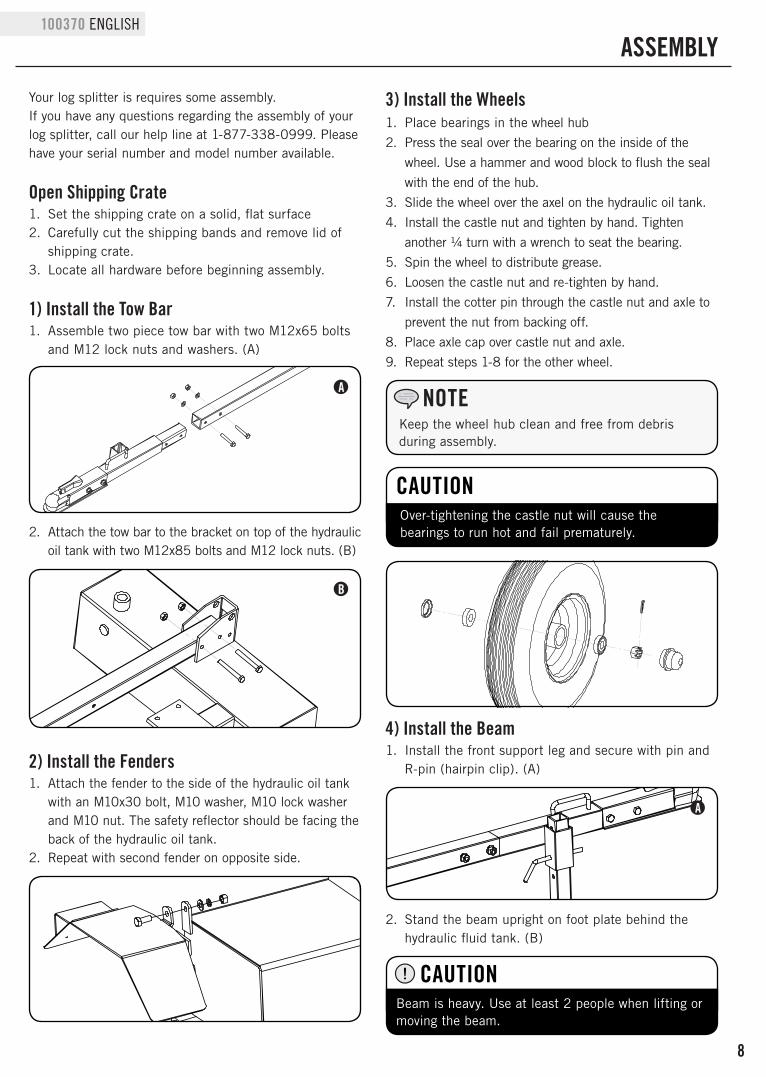
1) Install the Tow Bar1 . Assemble two piece tow bar with two M12x65 bolts
and M12 lock nuts and washers . (A)
2 . Attach the tow bar to the bracket on top of the hydraulic oil tank with two M12x85 bolts and M12 lock nuts . (B)
3) Install the Wheels1 . Place bearings in the wheel hub
2 . Press the seal over the bearing on the inside of the
wheel . Use a hammer and wood block to flush the seal
with the end of the hub .
3 . Slide the wheel over the axel on the hydraulic oil tank .
4 . Install the castle nut and tighten by hand . Tighten
another ¼ turn with a wrench to seat the bearing .
5 . Spin the wheel to distribute grease .
6 . Loosen the castle nut and re-tighten by hand .
7 . Install the cotter pin through the castle nut and axle to
prevent the nut from backing off .
8 . Place axle cap over castle nut and axle .
9 . Repeat steps 1-8 for the other wheel .
Keep the wheel hub clean and free from debris during assembly .
NOTE
B
Over-tightening the castle nut will cause the bearings to run hot and fail prematurely .
CAUTION
2) Install the Fenders1 . Attach the fender to the side of the hydraulic oil tank
with an M10x30 bolt, M10 washer, M10 lock washer and M10 nut . The safety reflector should be facing the back of the hydraulic oil tank .
2 . Repeat with second fender on opposite side .
A
4) Install the Beam1 . Install the front support leg and secure with pin and
R-pin (hairpin clip) . (A)
2 . Stand the beam upright on foot plate behind the hydraulic fluid tank . (B)
Beam is heavy . Use at least 2 people when lifting or moving the beam .
CAUTION
9
ENGLISH 100370
ASSEMBLy
C
D
A
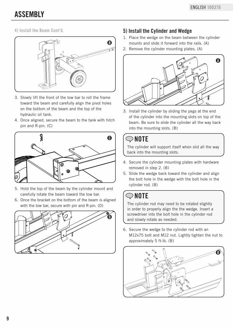
4) Install the Beam Cont’d. 5) Install the Cylinder and Wedge1 . Place the wedge on the beam between the cylinder
mounts and slide it forward into the rails . (A)2 . Remove the cylinder mounting plates . (A)
3 . Install the cylinder by sliding the pegs at the end of the cylinder into the mounting slots on top of the beam . Be sure to slide the cylinder all the way back into the mounting slots . (B)
The cylinder will support itself when slid all the way back into the mounting slots .
NOTE
4 . Secure the cylinder mounting plates with hardware removed in step 2 . (B)
5 . Slide the wedge back toward the cylinder and align the bolt hole in the wedge with the bolt hole in the cylinder rod . (B)
6 . Secure the wedge to the cylinder rod with an M12x75 bolt and M12 nut . Lightly tighten the nut to approximately 5 ft-lb . (B)
B
The cylinder rod may need to be rotated slightly in order to properly align the the wedge . Insert a screwdriver into the bolt hole in the cylinder rod and slowly rotate as needed .
NOTE
B
3 . Slowly lift the front of the tow bar to roll the frame toward the beam and carefully align the pivot holes on the bottom of the beam and the top of the hydraulic oil tank .
4 . Once aligned, secure the beam to the tank with hitch pin and R-pin . (C)
5 . Hold the top of the beam by the cylinder mount and carefully rotate the beam toward the tow bar .
6 . Once the bracket on the bottom of the beam is aligned with the tow bar, secure with pin and R-pin . (D)

10
100370 ENGLISH
ASSEMBLy
6) Install the Engine and Hoses Cont’d.6) Install the Engine and Hoses
1 . Attach the engine/pump to the engine mounting plate on the hydraulic oil tank . (A)
2 . Place O-ring into the outlet fitting on the top of the pump . (A)
3 . Connect one end of the high pressure hose to the pump outlet fitting and the other end to the inlet on the control valve . (B)
The swivel nut end of the high pressure hose connects to the pump outlet .
NOTE
4 . Connect one end of the clear oil hose to the hydraulic oil tank just beneath the engine and the other end to the pump inlet on the bottom of the pump . (C)
C
B
A
D
1 . Attach log catcher to side of beam with four M10x15
bolts, four M10 lock washers, and four M10 washers .
2 . Repeat step 1 for the other side .
7) Install the Log Catchers
Red shipping plugs must be removed from hydraulic pump prior to installing hoses .
Hydraulic pump may contain residual oil from testing procedures during production . We recommend using an oil tray under the pump before removing the shipping plugs .
CAUTION
5 . Connect one end of the oil return hose to the outlet barb fitting on the control valve and the other end to the barb fitting on the oil tank . (D)
11
ENGLISH 100370
ASSEMBLy
5 . Replace and tighten the oil plug and orient the vent
hole away from the operator zone .
6 . Start Engine . (Refer to Honda engine Owner’s
Manual .)
7 . Extend and retract the wedge to purge air from the
hydraulic system . When the wedge motion is smooth,
the system is properly purged .
8 . Check the hydraulic oil tank sight glass . Add
approximately 3 .8 L (1 gallon) of hydraulic oil to
bring the level back up to the sight glass . Do NOT
overfill .
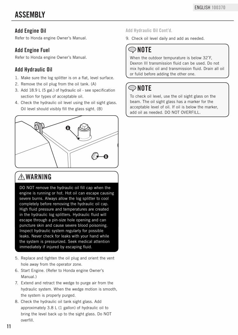
DO NOT remove the hydraulic oil fill cap when the engine is running or hot . Hot oil can escape causing severe burns . Always allow the log splitter to cool completely before removing the hydraulic oil cap . High fluid pressure and temperatures are created in the hydraulic log splitters . Hydraulic fluid will escape through a pin-size hole opening and can puncture skin and cause severe blood poisoning . Inspect hydraulic system regularly for possible leaks . Never check for leaks with your hand while the system is pressurized . Seek medical attention immediately if injured by escaping fluid .
WARNING
Add Hydraulic Oil1 . Make sure the log splitter is on a flat, level surface .
2 . Remove the oil plug from the oil tank . (A)
3 . Add 18 .9 L (5 gal .) of hydraulic oil - see specification
section for types of acceptable oil .
4 . Check the hydraulic oil level using the oil sight glass .
Oil level should visibly fill the glass sight . (B)
A
B
Add Engine FuelRefer to Honda engine Owner’s Manual .
Add Engine OilRefer to Honda engine Owner’s Manual .
Add Hydraulic Oil Cont’d.
When the outdoor tempurature is below 32˚F, Dexron III transmission fluid can be used . Do not mix hydraulic oil and transmission fluid . Drain all oil or fulid before adding the other one .
NOTE
To check oil level, use the oil sight glass on the beam . The oil sight glass has a marker for the acceptable level of oil . If oil is below the marker, add oil as needed . DO NOT OVERFILL .
NOTE
9 . Check oil level daily and add as needed .
12
100370 ENGLISH
OPERATION
Before Each Use Inspect the Log Splitter1 . Check the hydraulic oil level and visually inspect all
hoses, attachments and cylinder for leaks, cracks, fraying or other damage .
2 . DO NOT operate the log splitter if there is any indication of damage or oily residue .
3 . Inspect the engine and make sure the oil level is correct before operating . If the engine is equipped with a spark arrestor, clean and inspect it regularly (follow spark arrestor maintenance schedule) .
4 . The tires need to be fully inflated and in good repair . Reference the tire sidewall for recommended tire pressure .
Log Splitter LocationThis log splitter must have at least 2 .1 m (7 ft .) of clearance from combustible material . Leave at least 91 .4 cm (3 ft .) of clearance on all sides of the log splitter to allow for adequate cooling, maintenance and servicing . DO NOT place the log splitter near vents or intakes where engine exhaust fumes could be drawn into occupied or confined spaces . Always operate the log splitter outdoors.
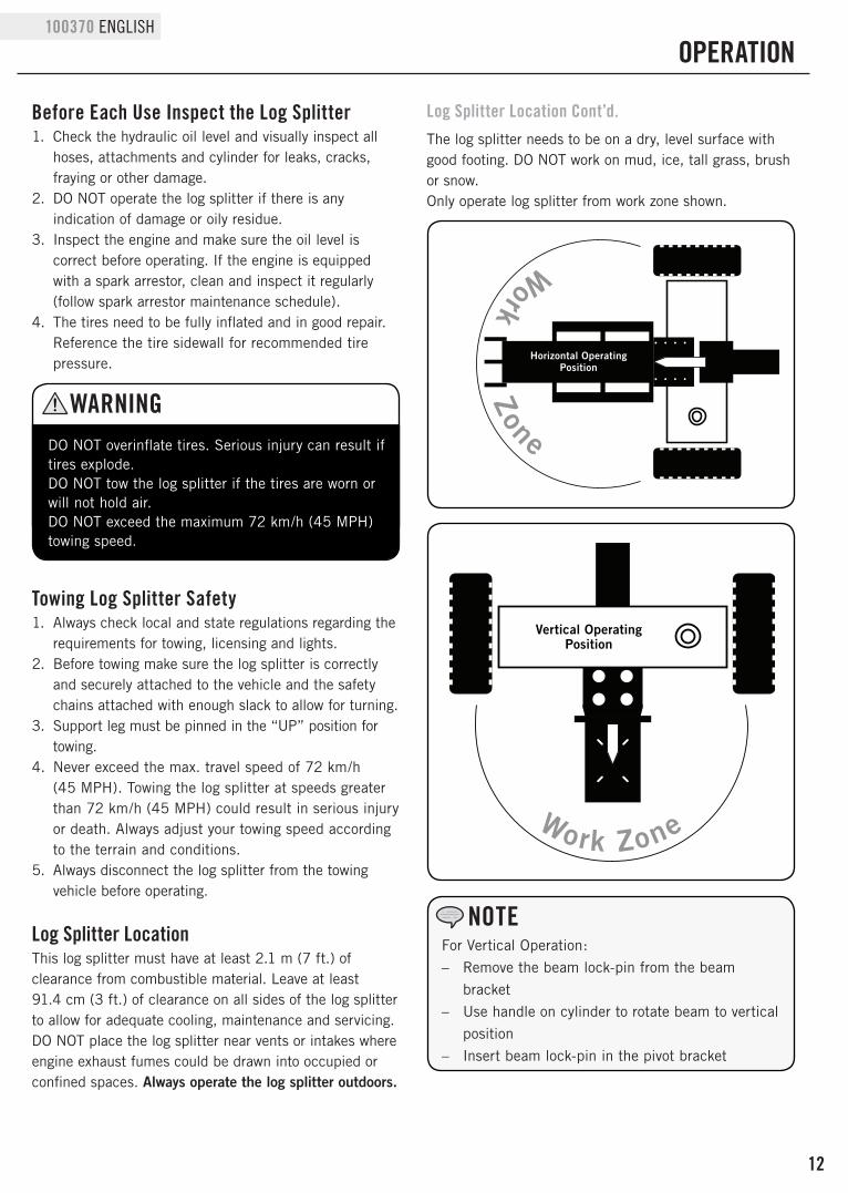
Vertical OperatingPosition
Work Zone
Horizontal OperatingPosition
Work Zone
Log Splitter Location Cont’d.
For Vertical Operation:
– Remove the beam lock-pin from the beam
bracket
– Use handle on cylinder to rotate beam to vertical
position
– Insert beam lock-pin in the pivot bracket
NOTE
DO NOT overinflate tires . Serious injury can result if tires explode . DO NOT tow the log splitter if the tires are worn or will not hold air . DO NOT exceed the maximum 72 km/h (45 MPH)towing speed .
WARNING
Towing Log Splitter Safety1 . Always check local and state regulations regarding the
requirements for towing, licensing and lights .2 . Before towing make sure the log splitter is correctly
and securely attached to the vehicle and the safety chains attached with enough slack to allow for turning .
3 . Support leg must be pinned in the “UP” position for towing .
4 . Never exceed the max . travel speed of 72 km/h (45 MPH) . Towing the log splitter at speeds greater than 72 km/h (45 MPH) could result in serious injury or death . Always adjust your towing speed according to the terrain and conditions .
5 . Always disconnect the log splitter from the towing vehicle before operating .
The log splitter needs to be on a dry, level surface with good footing . DO NOT work on mud, ice, tall grass, brush or snow .Only operate log splitter from work zone shown .

13
ENGLISH 100370
OPERATION
Starting the EngineRefer to Honda engine Owner’s Manual .
ALWAYS use the log splitter for its intended use . The log splitter should only be used to split wood logs, length wise with the grain . NEVER modify, alter or change the log splitter in anyway . Modifications will void the warranty . NEVER attach a rope, cable or other device to the control lever on the log splitter . DO NOT modify or change the engine and operating speeds or pressure settings . These changes can cause safety issues . ONLY operate the log splitter in daylight . NEVER operate, or let anyone else operate, the log splitter while under the influence of alcohol, drugs, or medication . NEVER leave the log splitter unattended while the engine is running . DO NOT change the splitting position with the engine running . Contact with the muffler can cause serious burns . Always make sure the beam is in the locked position . DO NOT let the beam drop as it could crush fingers or cause damage to the log splitter .
WARNING
Log Splitter Location Cont’d. Log Splitter Operation Cont’d.
Stopping the EngineRefer to Honda engine Owner’s Manual .
HORIZONAL position is used for lighter logs that can easily be loaded onto the beam .VERTICAL position is used for light logs as well as heavy logs that are difficult to load onto the beam .Back injury can result from lifting logs onto the log splitter if proper lifting techniques are not used .
NOTE
Log Splitter Operation1 . ALWAYS wear ear and eye protection, protective clothing
and safety gear .
2 . Block tires and put support leg in the DOWN position
to prevent unintended movement of the log splitter
during operation .
3 . Set log splitter in either the horizontal or vertical
position .
4 . Load a log onto the beam against the end plate
(MAX LOG LENGTH – 60 .3 cm {23 .8 in .}) .
5 . Make sure all limbs are clear of crush zones .
6 . Push the control valve handle forward (towards the
end plate) to split the log .
7 . Push the auto control valve handle backward to
return the wedge to its original position .
8 . Clear the split wood from the work zone .
If a log gets stuck, embedded or will not split completely, push the control handle in the reverse direction and allow the splitter to strip the log from the wedge .ALWAYS keep hands clear of the log and wedge while it is retracting .
NOTE
The cylinder stroke is designed so the wedge stops approximately 3 .8 cm (1 .5 in .) from the end plate .
NOTE
It is normal for the hydraulic fluid to appear foamy/frothy during operation . This can be caused by agitated oil in the tank collecting air .
NOTE
Do not hold auto control valve in return position . It will damage the stop block or beam .
CAUTION

14
100370 ENGLISH
Hydraulic Oil Cont’d.
MAINTENANCE AND STORAGE
The owner/operator is responsible for all periodic maintenance .
Complete all scheduled maintenance in a timely manner . Correct any issue before operating the log splitter .
For service or parts assistance, contact our help line at 1-877-338-0999 .
NOTE
When log splitters are not used for extended periods of time and they are exposed to changing temperature conditions, moisture through condensation can build up inside the tank
NOTE
The drain plug is sealed with Teflon® tape . Add 2-3 wraps of new Teflon® tape as needed when replacing the drain plug to prevent oil leak .
NOTE
Oil will drain from the filter and filter housing .
NOTE
Install a new hydraulic oil filter each time the hydraulic oil is changed (if your log splitter includes this feature) .
NOTE
Never operate a damaged or defective log splitter .
WARNING
Improper maintenance will void your warranty .
WARNING
Engine MaintenanceRefer to Honda engine Owner’s Manual .
Hydraulic OilAlways shut off the engine, disconnect the spark plug .Change the hydraulic oil filter after the first 50 hours of use, then every 100 hours or seasonally .
Log Splitter MaintenanceMake certain that the log splitter is kept clean and stored properly . Only operate the unit on a flat, level surface in a clean, dry operating environment . DO NOT expose the unit to extreme conditions, excessive dust, dirt, moisture or corrosive vapours .Inspect all air vents and cooling slots to ensure that they are clean and unobstructed .Clean spark arrester every 100 hours .Check and tighten all bolts and nuts before operating the log splitter .
1 . Begin with the cylinder retracted and the engine
switch in the “OFF” position .
2 . Turn the fuel valve to the “OFF” position . (Refer to
Honda engine Owner’s Manual .)
3 . Release any stored pressure by moving the valve
lever forward and backward several times .
4 . Place a container under the hydraulic tank . Make
sure it is large enough to hold the contents of the
tank . See model specification section of this manual
for hydraulic oil capacities .
5 . To drain the oil,
a . Place an oil drain container under the drain plug .
Unscrew (counter-clockwise) and remove the
tank drain plug on the bottom of the hydraulic
tank . Allow oil to completely drain from the tank
into the container . Re-apply Teflon® sealing tape
to the drain plug threads, then reinsert and turn
(clockwise) in the tank drain plug . Tighten, but do
not over tighten .
b . Place an oil drain container under the external oil
filter (If your log splitter includes this feature) .
If not, skip to step “C” . Unscrew (counter-
clockwise) and remove the external hydraulic
oil filter and drain any oil in the filter into the
container . A strap or oil filter wrench may be
needed .
i . Locate an approved replacement filter .
ii . Lubricate the gasket of the new filter with a
thin film of clean oil .
iii . Install a new hydraulic oil filter (A) . Screw the
new filter on clockwise . Tighten 3/4 - 1 turn
after the gasket makes contact .
c . Place an oil drain container under the large clear
hose that runs from the tank to the pump .
i . Loosen the hose clamp attached to the fitting
on the tank .

15
ENGLISH 100370
MAINTENANCE AND STORAGE
Maintenance ScheduleFollow the service intervals indicated in the schedule
below . Service your log splitter more frequently when
operating in adverse conditions . Contact our help line at
1-877-338-0999 to locate the nearest Champion Power
Equipment authorized service dealer for your log splitter
or engine maintenance needs .
Every 8 hours or daily
Check engine and hydraulic oil levels
Every 100 hours or every season
Change hydraulic oil
Change hydraulic oil filter
Every year
Inspect wheel bearings and repack bearing grease as needed
Engine and Fuel Maintenance
Refer to Honda engine Owner’s Manual
Hydraulic Oil Cont’d. Hydraulic Oil Cont’d.
ii . Disconnect hose from fitting and drain oil into
the container .
iii . Using a large wrench, unscrew the fitting from
the tank to expose the internal tank filter .
iv . Check for any debris on the screen . Using a
clean towel or air gun, carefully remove any
debris .
Be careful when handling the screen as it can be
easily damaged .
NOTE
v . Apply new Teflon® sealing tape to threads,
reinsert into tank and tighten . Be careful to
tighten, but do not over tighten .
6 . Unscrew and remove the tank fill plug on top of the
tank . Using a funnel add approximately 18 .9 L
(5 gal .) of hydraulic oil to the tank . Wipe up any
spilled oil . (B)
7 . Turn the fuel valve to the “ON” position, and start
the engine (refer to Honda engine Owner’s Manual) .
Purge the air from the system by extending and
retracting the wedge several times until the motion is
smooth .
8 . Check the hydraulic oil level using the sight glass .
Add 3 .8 – 5 .7 L (1 - 1 .5 gal .) of hydraulic oil, so the
oil level is visible in the sight glass . (C)
9 . Dispose of used oil at approved recycling locations in
accordance with Federal, State, Local or Provincial
regulations .
DO NOT use a garden hose to clean the engine or log splitter .
CAUTION
Water can contaminate the fuel system and can enter the engine through the cooling slots and damage the engine .
Cleaning
Clear the debris from the beam, wedge and endplate . Use a damp cloth to clean exterior surfaces of the engine and log splitter .Use a soft bristle brush to remove excess dirt and oil . Use an air compressor (25 PSI) to clear dirt and small debris .Wipe all metal parts with an oily rag to help prevent rust and corrosion .
B
AC
Always shut off the engine, disconnect the spark plug, and relieve system pressure before cleaning, adjusting, or repairing the splitter . Relieve system pressure by moving split control lever back and forth several times
WARNING
Refer to Specifications for a list of compatible replacement filters or call Champion Power Equipment at 1-877-338-0999 to order a replacement OEM filter .
NOTE
16
100370 ENGLISH
MAINTENANCE AND STORAGE
Never store the log splitter inside next to appliances where there is a source of heat or open flame, spark or pilot light because they can ignite gasoline vapors . DO NOT store a log splitter near fertilizer or any corrosive material . Even with an empty gas tank, gasoline vapors could ignite .
WARNING
StorageRefer to the Maintenance section for proper cleaning
instructions .
Log Splitter Storage1 . The log splitter needs to be cool for at least 5
minutes before storing .
2 . Clean the log splitter before storage according to the
Maintenance section .
3 . Retract the wedge to protect the rod from corrosion .
4 . Wipe the beam and wedge with an oily rag to prevent
rust and corrosion .
Engine StorageRefer to Honda engine Owner’s Manual

17
ENGLISH 100370
TROUBLESHOOTING
For further technical support:
Technical ServiceMon – Fri 8:30 AM – 5:00 PM (PST/PDT)Toll Free: 1-877-338-0999tech@championpowerequipment .com
Problem Cause Solution
Engine will not start
No fuel Add fuel
Faulty spark plug Replace spark plug
Unit loaded during startup Remove load from unit
Engine starts but runs roughly
Low oil levelFill crankcase to the proper level
Place log splitter on a flat, level surface
Choke in the wrong position Adjust choke
Spark plug wire loose Attach wire to spark plug
Engine shuts down during operation
Out of fuel Fill fuel tank
Low oil levelFill crankcase to the proper level
Place log splitter on a flat, level surface
Engine cannot supply enough power or overheating
Insufficient ventilationCheck for air restriction . Move to a well ventilated area
Wedge movement is slow or erratic
Air in the hydraulic oil systemPurge air by extending and retracting the wedge several times until motion is smooth
Debris lodged in beam guides Clear debris from beam
Low hydraulic oil Check oil level and add as needed
Oil leak from hose connection Loose hose clamp or hydraulic fitting Tighten hose clamp or hydraulic fitting
Oil leak from cylinder
Faulty cylinder rod seal Contact Customer Service
Scored or bent cylinder rod Contact Customer Service
Loose hydraulic fitting Tighten hydraulic fitting
Faulty combination washer seal on cylinder hydraulic fitting
Contact Customer Service
Wedge will not extend or retract
Faulty control valve Contact Customer Service
Faulty hydraulic pump Contact Customer Service
Low hydraulic oil Check oil level and add as needed
Wedge does not Auto-ReturnLow hydraulic oil Check oil level and add as needed
Faulty control valve Contact Customer Service
Excessive bouncing while towing Under-inflated tiresInflate tires to proper pressure . Refer to tire sidewall
18
100370 ENGLISH
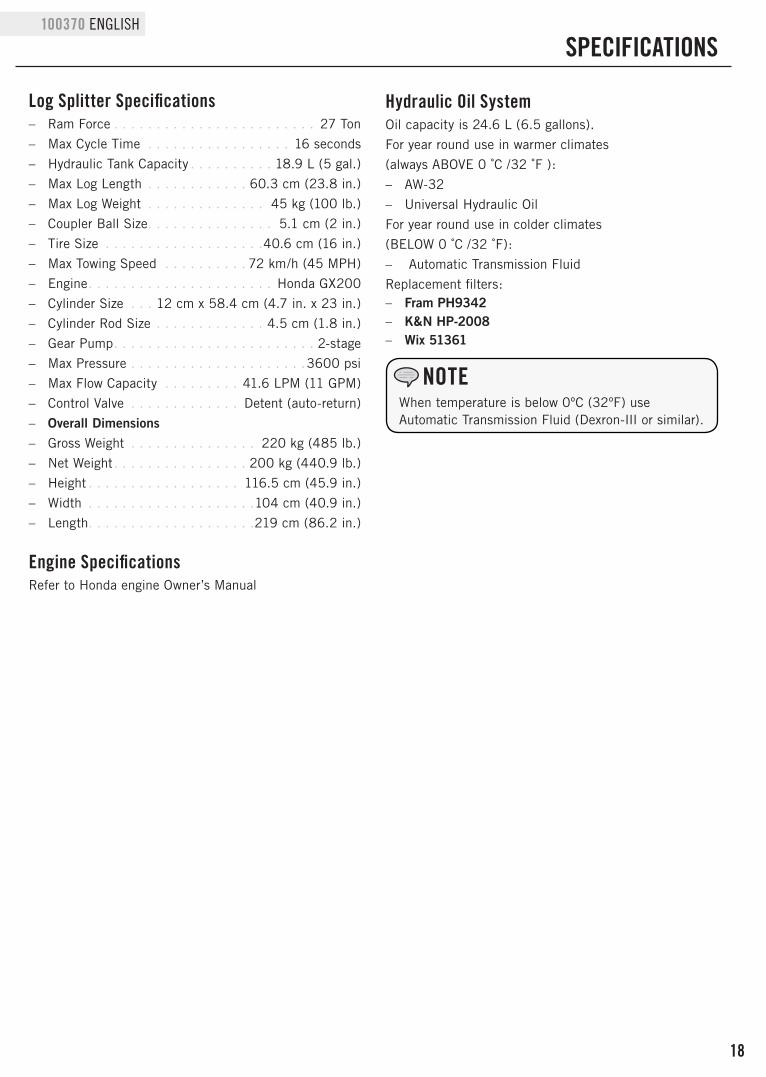
SPECIFICATIONS
When temperature is below 0ºC (32ºF) use Automatic Transmission Fluid (Dexron-III or similar) .
NOTE
Log Splitter Specifications – Ram Force . . . . . . . . . . . . . . . . . . . . . . . . 27 Ton
– Max Cycle Time . . . . . . . . . . . . . . . . . 16 seconds
– Hydraulic Tank Capacity . . . . . . . . . . 18 .9 L (5 gal .)
– Max Log Length . . . . . . . . . . . . 60 .3 cm (23 .8 in .)
– Max Log Weight . . . . . . . . . . . . . . 45 kg (100 lb .)
– Coupler Ball Size . . . . . . . . . . . . . . . 5 .1 cm (2 in .)
– Tire Size . . . . . . . . . . . . . . . . . . .40 .6 cm (16 in .)
– Max Towing Speed . . . . . . . . . . 72 km/h (45 MPH)
– Engine . . . . . . . . . . . . . . . . . . . . . . Honda GX200
– Cylinder Size . . . 12 cm x 58 .4 cm (4 .7 in . x 23 in .)
– Cylinder Rod Size . . . . . . . . . . . . . 4 .5 cm (1 .8 in .)
– Gear Pump . . . . . . . . . . . . . . . . . . . . . . . . 2-stage
– Max Pressure . . . . . . . . . . . . . . . . . . . . .3600 psi
– Max Flow Capacity . . . . . . . . . 41 .6 LPM (11 GPM)
– Control Valve . . . . . . . . . . . . . Detent (auto-return)
– Overall Dimensions – Gross Weight . . . . . . . . . . . . . . . 220 kg (485 lb .)
– Net Weight . . . . . . . . . . . . . . . . 200 kg (440 .9 lb .)
– Height . . . . . . . . . . . . . . . . . . 116 .5 cm (45 .9 in .)
– Width . . . . . . . . . . . . . . . . . . . .104 cm (40 .9 in .)
– Length . . . . . . . . . . . . . . . . . . . .219 cm (86 .2 in .)
Hydraulic Oil SystemOil capacity is 24 .6 L (6 .5 gallons) .
For year round use in warmer climates
(always ABOVE 0 ˚C /32 ˚F ):
– AW-32
– Universal Hydraulic Oil
For year round use in colder climates
(BELOW 0 ˚C /32 ˚F):
– Automatic Transmission Fluid
Replacement filters: – Fram PH9342 – K&N HP-2008 – Wix 51361
Engine SpecificationsRefer to Honda engine Owner’s Manual

19
ENGLISH 100370
Parts Diagram
SPECIFICATIONS
TO(A)
(A)
TO(B)
TO(C)
TO(D)
(B)
(C)(D)
TO(E)
(E)
TO(F)
(F)

20
100370 ENGLISH
# Part Number Description Qty1 PMJ27-02-00 Beam 1
2GB/T 5782-2000(M12 x 75)
Bolt M12 x 75(12 .9) 1
3 PMJ22J-04-00 Wedge Slide 1
4 GB/T 95-2000(Ø12) Washer Ø12 7
5GB/T 889 .1-2000(M12)
Lock Nut M12 7
6 PMJ22G-51 Control Valve "IN" Connector 1
7 PMJ22J-12 Control Valve 1
8 PMJ22J-19 Plate 1
9GB/T 818-2000(M8 x 12)
Bolt M8 x 12 2
10 GB/T 859-1987(Ø8) Washer Ø8 2
11 PMJ22G-49 Control Valve "OUT" Connector 2
12 JB/T 8870-1999(d25) Clamp d25 2
13 PMJ7-15 Right Angle Joiner 2
14 PMJ7-22 Through Joiner 1
15 PMJ30-16A Hydraulic Hose(Valve-Cylinder) 1
16 PMJ30-08A-00 Cylinder 1
17 PMJ22G-15 Hydraulic Hose(Valve-Oil Tank) 1
18 PMJ22J-06 Base Tube 1
19 PMJ23-01-00 Base Connector 1
20 PMJ22J-10 Pin 1
21 PMJ22G-30 R Pin 2
22 PMJ22G-40 2-in . Coupler 1
23GB/T 5782-2000(M12 x 80)
Bolt M12 x 80 2
24GB/T 5782-2000(M10 x 85)
Bolt M10 x 85 1
25GB/T 889 .1-2000(M10)
Lock Nut M10 1
26 PMJ25M-18-00 Safety Chain With Hook 2
27 PMJ22J-07-00 Front Support Leg 1
28GB/T 5782-2000(M12 x 65)
Bolt M12 x 65 2
29 PMJ22J-18 Hydraulic Hose(Valve-Pump) 1
30GB/T 3452 .1-92(10 x 2 .65)
"O" Ring 10 x 2 .65 1
31 PMJ22G-21 Outlet Connector Of Pump 1
32 PMJ22J-14 Gear Pump 1
33JB/T 8870-1999(d40)
Clamp d40 2
34 PMJ22G-17 Oil Pipe 1
35GB/T 5783-2000(M8 x 30)
Bolt M8 x 30 4
36 GB/T 95-2000(Ø8) Washer Ø8 16
37 GB/T 93-1987(Ø8) Lock Washer Ø8 16
38 GB/T 6170-2000(M8) Nut M8 9
39GB/T 77-2000(M6 x 10)
Screw M6 x 10 1
40 PMJ22G-26 Gear Pump Connector 1
41 ASME B18 .2 .1 1996 Bolt 5/16"-24×1" 4
42 PMJ22G-29 Engine Bushing 1
43 GX200 Engine (Honda) 1
# Part Number Description Qty44 GB/T 1096-1979 Flat Key 5 x 5 1
45 PMJ22G-28 Engine Connector 1
46 PMJ22G-27 Gear Pump Stand 1
47 PMJ22G-32 Connector Cover 1
48 GB/T 845C-1985 Tapping Screw 4
49 GB/T 848-1985(Ø4) Lock Washer Ø4 4
50 GB/T 859-1987(Ø4) Washer Ø4 4
51 GB/T 1099-1979 Flat Key 3 x 3 1
52 PMJ22Q-22 Filter Connector 1
53 PMJ22Q-20 Internal Oil Filter 1
54 PMJ22G-19 Oil Plug 1
55GB/T 5782-2000(M8 x 45)
Bolt M8 x 45 4
56 PMJ22J-05-02 Axle Cap 2
57GB/T 9459-1988(M20 x 1 .5)
Slotted Nut M20 x 1 .5 2
58 L44634 LYC DS Tapered Bearing 4
59 PMJ37N-05 Wheel 2
60 PMJ22J-05-01 Cased Seal 2
61GB/T 91-2000(4 x 32)
Cotter Pin 4 x 32 2
62 PMJ27-01-00 Oil Tank 1
63 PMJ22G-12 Hinge Pin 1
64GB/T 5782-2000(M12 x 85)
Bolt M12 x 85 2
65 GJY12-3 R Pin 1
66 PMJ22G-18 Screw NPT 1-in . 1
67 GB 1160 .2-89 Oil Scale 1
68 PMJ22J-15 Pin 1
69GB/T 798-1988(M8 x 28)
Swing Bolt M8 x 28 1
70 PMJ22G-38 Big Tension Spring 1
71GB/T 5783-2000(M8 x 20)
Bolt M8 x 20 4
72 PMJ30-03 Cylinder Fixing Plate 2
73 PMJ30F-01-Y Log Catcher-Yellow 2
74 GB/T 95-2000(Ø10) Washer Ø10 16
75 GB/T 93-1987(Ø10) Lock washer Ø10 12
76GB/T 5781-2000(M10 x 15)
Bolt M10 x 15 8
77 PMJ22G-34-00 Left Fender 1
78 PMJ22G-35-00 Right Fender 1
79GB/T 5781-2000(M10 x 25)
Bolt M10 x 25 4
80GB/T 6170-2000(M10)
Nut M10 4

WARRANTy*CHAMPION POWER EQUIPMENT
2 YEAR LIMITED WARRANTY
For the engine warranty and technical service, refer to Honda Engine Owner’s Manual.
Warranty QualificationsChampion Power Equipment (CPE) will register this warranty upon receipt of your Warranty Registration Card and a copy of your sales receipt from one of CPE’s retail locations as proof of purchase .Please submit your warranty registration and your proof of purchase within ten (10) days of the date of purchase .
Repair/Replacement WarrantyCPE warrants to the original purchaser that the mechanical and electrical components will be free of defects in material and workmanship for a period of two years (parts and labor) from the original date of purchase and 180 days (parts and labor) for commercial and industrial use . Transportation charges on product submitted for repair or replacement under this warranty are the sole responsibility of the purchaser . This warranty only applies to the original purchaser and is not transferable .
Do Not Return The Unit To The Place Of PurchaseContact CPE’s Technical Service and CPE will troubleshoot any issue via phone or e-mail . If the problem is not corrected by this method, CPE will, at its option, authorize evaluation, repair or replacement of the defective part or component at a CPE Service Center . CPE will provide you with a case number for warranty service . Please keep it for future reference . Repairs or replacements without prior authorization, or at an unauthorized repair facility, will not be covered by this warranty .
Warranty ExclusionsThis warranty does not cover the following repairs and equipment:
Normal WearProducts with mechanical and electrical components need periodic parts and service to perform well . This warranty does not cover repair when normal use has exhausted the life of a part or the equipment as a whole .
Installation, Use and MaintenanceThis warranty will not apply to parts and/or labor if the product is deemed to have been misused, neglected, involved in an accident, abused, loaded beyond the product’s limits, modified, installed improperly or connected incorrectly to any electrical component . Normal maintenance is not covered by this warranty and is not required to be performed at a facility or by a person authorized by CPE .
Other ExclusionsThis warranty excludes: – Cosmetic defects such as paint, decals, etc . – Wear items such as filter elements, o-rings, etc . – Accessory parts such as starting batteries, and storage
covers . – Failures due to acts of God and other force majeure events
beyond the manufacturer’s control . – Problems caused by parts that are not original Champion
Power Equipment parts .When applicable, this warranty does not apply to products used for prime power in place of a utility .
Limits of Implied Warranty and Consequential DamageChampion Power Equipment disclaims any obligation to cover any loss of time, use of this product, freight, or any incidental or consequential claim by anyone from using this product . THIS WARRANTY AND THE ATTACHED U .S . EPA, CARB and/or ECCC EMISSION CONTROL SYSTEM WARRANTIES (WHEN APPLICABLE) ARE IN LIEU OF ALL OTHER WARRANTIES, EXPRESS OR IMPLIED, INCLUDING WARRANTIES OF MERCHANTABILITY OR FITNESS FOR A PARTICULAR PURPOSE . A unit provided as an exchange will be subject to the warranty of the original unit . The length of the warranty governing the exchanged unit will remain calculated by reference to the purchase date of the original unit .This warranty gives you certain legal rights which may change from state to state or province to province . Your state or province may also have other rights you may be entitled to that are not listed within this warranty .
Contact InformationAddressChampion Power Equipment, Inc .Customer Service12039 Smith Ave .Santa Fe Springs, CA 90670 USAwww .championpowerequipment .com
Customer ServiceMon – Fri 8:30 AM – 5:00 PM (PST/PDT)Toll Free: 1-877-338-0999info@championpowerequipment .comFax no .: 1-562-236-9429
Technical ServiceMon – Fri 8:30 AM – 5:00 PM (PST/PDT)Toll Free: 1-877-338-0999tech@championpowerequipment .com24/7 Tech Support: 1-562-204-1188
WARRANTy
* Except as otherwise stipulated in any of the following enclosed Emission Control System Warranties (when applicable) for the Emission Control System: U .S . Environment Protection Agency (EPA), California Air Resources Board (CARB) and/or Environment and Climate Change Canada (ECCC) .