2508 IEEE TRANSACTIONS ON SMART GRID, VOL. 5, …qu/Journals/2014 IEEE T SG September.pdfOptimal,...
9
2508 IEEE TRANSACTIONS ON SMART GRID, VOL. 5, NO. 5, SEPTEMBER 2014 Optimal, Nonlinear, and Distributed Designs of Droop Controls for DC Microgrids Ali Maknouninejad, Member, IEEE, Zhihua Qu, Fellow, IEEE, Frank L. Lewis, Fellow, IEEE, and Ali Davoudi, Member, IEEE Abstract—In this paper, the problem of optimal voltage and power regulation is formulated for distributed generators (DGs) in DC microgrids. It is shown that the resulting control is optimal but would require the full information of the microgrid. Relaxation of information requirement reduces the optimal control into several controls including the conventional droop control. The general setting of a DC microgrid equipped with local sensing/commu- nication network calls for the design and implementation of a cooperative droop control that uses the available local information and coordinates voltage control in a distributed manner. The pro- posed cooperative droop control is shown to include other controls as special cases, its performance is superior to the conventional droop control, and it is robust with respect to uncertain changes in both distribution network and sensing/communication network. These features make the proposed control an effective scheme for operating a DC microgrid with intermittent and distributed generation. Index Terms—Conventional droop control, cooperative droop control, DC microgrid, distributed generation, distribution net- work, smart grid. I. INTRODUCTION T HE electricity demand, combined with physical, econom- ical and environmental constraints of conventional en- ergy sources such as fossil and nuclear energy, is putting more emphasis on finding and utilizing alternative energy sources. Of special interest are renewable energy sources such as solar and wind energy generation. This has lead to the emergence of distributed generators (DGs), self-organizing microgrids, and smart grid. DGs may be heterogeneous as PV systems, wind turbines, fuel cells, and diesel generators. DG locations must be economically and physically feasible. To better harness alter- native energy or to serve critical loads, DGs are installed at the most economical and physically-feasible locations, and they are often dispersed widely across the distribution network. To prop- erly control and manage these DGs, it is natural to organize DGs in a given geographical area into a self-organizing microgrid Manuscript received August 02, 2013; revised December 19, 2013 and April 18, 2014; accepted May 15, 2014. Date of current version September 05, 2014. This work is supported in part by U.S. National Science Foundation (under grants ECCS-1308928 and CCF-0956501), by U.S. Department of Energy’s award DE-EE0006340 (under the Grid Engineering for Accelerated Renewable Energy Deployment program), and by US Department of Energy’s Solar Energy Grid Integration Systems program. Paper no. TSG-00576-2013. A. Maknouninejad was with the Department of Electrical Engineering and Computer Science, University of Central Florida, Orlando, FL 32816, USA. He is now with Alencon Systems Inc., Hatboro, PA 19040 USA. Z. Qu is with the Department of Electrical Engineering and Computer Sci- ence, University of Central Florida, Orlando, FL 32816 USA. F. L. Lewis and A. Davoudi are with the Department of Electrical Engi- neering, University of Texas, Arlington, TX 76019, USA. Color versions of one or more of the figures in this paper are available online at http://ieeexplore.ieee.org. Digital Object Identifier 10.1109/TSG.2014.2325855 Fig. 1. A general block diagram of a typical DC microgrid. which is connected to the main grid through point of common coupling (PCC). In current distribution networks, microgrids are in the AC form. A DC microgrid may coexist with the rest of the AC grid, power generation plants, and transmission networks. Many of DGs are in a DC form and, in order to have an AC system, DGs can use a DC/AC inverter stage to convert their DC current/ voltage into a grid quality AC current/voltage, but this extra stage increases cost and reduces efficiency. Therefore, there is resurgence of interests in DC microgrids, while the concept of DC microgrids were discussed in [1]. A typical structure of a DC microgrid [1] is shown in the Fig. 1. At the PCC, the microgrid is connected to the main grid through one bidirectional AC/DC converter (rather than several DC/AC inverters). In the microgrid, renewable energy sources and other DGs are connected to DC buses through DC/DC con- verters. Regular DC loads may be connected directly to any of DC buses, and critical DC loads that require an exact voltage regulation may utilize DC/DC converters at their connection points. Storage devices may or may not be affiliated with DGs. Similar to an AC microgrid, a hierarchical and multi level con- trol may be applied to control the DGs power generation and storages, to optimize the interests of both the microgrid/main- grid and individual devices, while securing the system stability [2]. However, as will be discussed in the subsequent discus- sions, cooperative droop control as an improved droop control may be applied at the level of DGs and storage units to guarantee the system stability and proper utilization of available resources in the microgrid, including DGs and storage. Potential advantages of a DC microgrid over the AC counter- part can be summarized as follows: 1) The majority of renewable energy sources (e.g., photo- voltaic) and storage systems (e.g., batteries) are natively DC. Emerging new loads are either DC loads (e.g., data centers) or AC loads that are driven by DC sources (e.g., in- verter-fed AC machines). It has been shown in [3], [4] that 1949-3053 © 2014 IEEE. Translations and content mining are permitted for academic research only. Personal use is also permitted, but republication/ redistribution requires IEEE permission. See http://www.ieee.org/publications_standards/publications/rights/index.html for more information.
Transcript of 2508 IEEE TRANSACTIONS ON SMART GRID, VOL. 5, …qu/Journals/2014 IEEE T SG September.pdfOptimal,...

2508 IEEE TRANSACTIONS ON SMART GRID, VOL. 5, NO. 5, SEPTEMBER 2014
Optimal, Nonlinear, and Distributed Designs ofDroop Controls for DC Microgrids
Ali Maknouninejad, Member, IEEE, Zhihua Qu, Fellow, IEEE, Frank L. Lewis, Fellow, IEEE, andAli Davoudi, Member, IEEE
Abstract—In this paper, the problem of optimal voltage andpower regulation is formulated for distributed generators (DGs) inDCmicrogrids. It is shown that the resulting control is optimal butwould require the full information of the microgrid. Relaxation ofinformation requirement reduces the optimal control into severalcontrols including the conventional droop control. The generalsetting of a DC microgrid equipped with local sensing/commu-nication network calls for the design and implementation of acooperative droop control that uses the available local informationand coordinates voltage control in a distributed manner. The pro-posed cooperative droop control is shown to include other controlsas special cases, its performance is superior to the conventionaldroop control, and it is robust with respect to uncertain changes inboth distribution network and sensing/communication network.These features make the proposed control an effective schemefor operating a DC microgrid with intermittent and distributedgeneration.Index Terms—Conventional droop control, cooperative droop
control, DC microgrid, distributed generation, distribution net-work, smart grid.
I. INTRODUCTION
T HE electricity demand, combined with physical, econom-ical and environmental constraints of conventional en-
ergy sources such as fossil and nuclear energy, is putting moreemphasis on finding and utilizing alternative energy sources.Of special interest are renewable energy sources such as solarand wind energy generation. This has lead to the emergence ofdistributed generators (DGs), self-organizing microgrids, andsmart grid. DGs may be heterogeneous as PV systems, windturbines, fuel cells, and diesel generators. DG locations must beeconomically and physically feasible. To better harness alter-native energy or to serve critical loads, DGs are installed at themost economical and physically-feasible locations, and they areoften dispersed widely across the distribution network. To prop-erly control and manage these DGs, it is natural to organize DGsin a given geographical area into a self-organizing microgrid
Manuscript received August 02, 2013; revised December 19, 2013 and April18, 2014; accepted May 15, 2014. Date of current version September 05, 2014.This work is supported in part by U.S. National Science Foundation (undergrants ECCS-1308928 and CCF-0956501), by U.S. Department of Energy’saward DE-EE0006340 (under the Grid Engineering for Accelerated RenewableEnergy Deployment program), and by USDepartment of Energy’s Solar EnergyGrid Integration Systems program. Paper no. TSG-00576-2013.A. Maknouninejad was with the Department of Electrical Engineering and
Computer Science, University of Central Florida, Orlando, FL 32816, USA. Heis now with Alencon Systems Inc., Hatboro, PA 19040 USA.Z. Qu is with the Department of Electrical Engineering and Computer Sci-
ence, University of Central Florida, Orlando, FL 32816 USA.F. L. Lewis and A. Davoudi are with the Department of Electrical Engi-
neering, University of Texas, Arlington, TX 76019, USA.Color versions of one or more of the figures in this paper are available online
at http://ieeexplore.ieee.org.Digital Object Identifier 10.1109/TSG.2014.2325855
Fig. 1. A general block diagram of a typical DC microgrid.
which is connected to the main grid through point of commoncoupling (PCC).In current distribution networks, microgrids are in the AC
form. A DC microgrid may coexist with the rest of the AC grid,power generation plants, and transmission networks. Many ofDGs are in a DC form and, in order to have an AC system, DGscan use a DC/AC inverter stage to convert their DC current/voltage into a grid quality AC current/voltage, but this extrastage increases cost and reduces efficiency. Therefore, there isresurgence of interests in DC microgrids, while the concept ofDC microgrids were discussed in [1].A typical structure of a DC microgrid [1] is shown in the
Fig. 1. At the PCC, the microgrid is connected to the main gridthrough one bidirectional AC/DC converter (rather than severalDC/AC inverters). In the microgrid, renewable energy sourcesand other DGs are connected to DC buses through DC/DC con-verters. Regular DC loads may be connected directly to any ofDC buses, and critical DC loads that require an exact voltageregulation may utilize DC/DC converters at their connectionpoints. Storage devices may or may not be affiliated with DGs.Similar to an AC microgrid, a hierarchical and multi level con-trol may be applied to control the DGs power generation andstorages, to optimize the interests of both the microgrid/main-grid and individual devices, while securing the system stability[2]. However, as will be discussed in the subsequent discus-sions, cooperative droop control as an improved droop controlmay be applied at the level of DGs and storage units to guaranteethe system stability and proper utilization of available resourcesin the microgrid, including DGs and storage.Potential advantages of a DC microgrid over the AC counter-
part can be summarized as follows:1) The majority of renewable energy sources (e.g., photo-voltaic) and storage systems (e.g., batteries) are nativelyDC. Emerging new loads are either DC loads (e.g., datacenters) or AC loads that are driven byDC sources (e.g., in-verter-fed AC machines). It has been shown in [3], [4] that
1949-3053 © 2014 IEEE. Translations and content mining are permitted for academic research only. Personal use is also permitted, but republication/redistribution requires IEEE permission. See http://www.ieee.org/publications_standards/publications/rights/index.html for more information.

MAKNOUNINEJAD et al.: OPTIMAL, NONLINEAR, AND DISTRIBUTED DESIGNS OF DROOP CONTROLS FOR DC MICROGRIDS 2509
DC microgrids are about two orders-of-magnitudes moreavailable than their ac counterparts.
2) DC microgrids have simpler models and controls (i.e., nophase angle or frequency or reactive power), while syn-chronization, reactive power flow and harmonics have tobe considered for ac systems.
3) DC microgrids would significantly improve system re-liability, efficiency, and economy by eliminating theDC/AC/DC conversion stages [5], [6]. Since reactancehas little effect, a cable could carry more DC power thanAC power [1], [7].
Some of the challenges associated with DC distribution systemshave been investigated in [1]. In particular, the interaction be-tween different power converters and neutral voltage shifts arediscussed. A technique of connecting the microgrid to and dis-connecting the microgrid from the main power system is studiedby [8]. An energy management system (EMS) is proposed in [9]to incorporate into a DC distribution system the charge and dis-charge of electric vehicles.There is an abundance of research and literature covering AC
microgrids and DGs management [10]–[16], but an investiga-tion into the microgrid/grid level control of DGs in a DC mi-crogrid remains open to investigation. One exception is [17] inwhich applications of the conventional droop control to both DCand AC microgrids are investigated. This paper aims at devel-oping systematic designs and analysis for controlling DC mi-crogrids.In this paper, the problem of voltage and power regulation
by DGs in a DC microgrid is formulated as an optimal con-trol problem, and the resulting optimal control is used as theseed controller to investigate its variations in terms of informa-tion needed. By further advancing the application of cooperativecontrol fromAC network [2], [18]–[20] to DCmicrogrids, a dis-tributed droop control (called cooperative droop) is proposed.The main objective of cooperative droop control is to utilize theavailable information (from low-bandwidth local communica-tion links) and to improve the overall voltage profile by coordi-nating the neighboring control actions.
II. DC MICROGRID MODEL FORMULATION
Consider a DC microgrid which consists of nodes andwhose circuit network has the following admittance matrix
if
if(1)
where is the line admittance between nodes and, and is the admittance between node and the ground, ifthere is any. Topology of the microgrid can be represented by aphysical-connectivity graph , where denotes the setof nodes (with the th node being the ground)and denotes the set of undirected edges (for whichor ).The microgrid contains DGs (whether they are PV, wind,
biomass, or their combinations) and, if it is grid-tied, the powerfrom the grid (of node 0) is injected into node 1. These DGsmayhave different dynamics, and the use of power electronic de-vices will be a common practice for connecting DGs to the restof the system in the future smart grids. Such power electronicconverters have a fast transient response, in terms of few mil-
liseconds or faster, and upon applying the feedback linearizationmethod, their dynamics are assumed to be
(2)
where is the time constant (whose value is typicallysmall), and is the index set of those nodes where thereare DGs installed. Variables and are the power commandand the actual power output of the th DG, respectively. Accord-ingly, the power flow equations of the DC microgrid are givenby
(3)
where if , is the voltage at node , andrepresents the load at node .All of the electrical and control variables in (2) and (3)
are assumed to be of per-unit values. The objective of theproposed control designs is threefold: i) Ensure exponen-tial stability under constraints of (3); ii) achieve the goal of
and minimize the loss as much as possible;iii) design the best control with respect to available informa-tion. Three information patterns will be investigated: weaklyglobal information of , decentralized information of , anddistributed information of . The distributed information struc-ture is represented by an intermittent sensing/communicationdigraph , where denotes the set of nodes (or
nodes including node 0 if grid tied) and denotesthe set of directed edges. Alternatively, the local informationflow can be characterized by the binary sensing/communicationmatrix
(4)
where , if (i.e., isavailable to node at the time ), and if otherwise.At time , the neighboring set of node consists of thosenodes fromwhich communication is received (i.e.,
).
III. BASIC DESIGNS OF OPTIMAL CONTROL AND DROOPCONTROL
In this section, an optimal design framework is presented toderive a nonlinear optimal control. It is shown that this seedcontrol design can reduce to a linear global-information voltage-feedback control, a decentralized droop control, and an adaptivecontrol. The discussions provide the motivations for designinga distributed droop control in the subsequent section.
A. An Optimal Design
The following theorem provides an optimal control as theseed controller in the subsequent analysis, and its proof is in-cluded in Appendix A.Theorem 1: Consider the DC microgrid consisting of DGs in
(2) and under the control law
(5)

2510 IEEE TRANSACTIONS ON SMART GRID, VOL. 5, NO. 5, SEPTEMBER 2014
Fig. 2. Droop curves for DGs with and without storage. (a) Droop curve forDGs with storage; (b) droop curve for DGs without storage.
where and satisfy power flow (3). Then, control (5) isoptimal with respect to performance index
(6)where is given, and . Further-more, the control ensures that converges globally and expo-nentially to its steady state of .Should control (5) be implemented, desired values andneed to be chosen. Its implementation also requires , that
is, all the information about the DC microgrid. In what follows,several choices and simplifications are investigated.
B. Uniform Terminal Voltages Under Unconstrained DGs
If DGs have sufficient capacity/storage capability, couldbe chosen such that for all . In this case, control(5) becomes
(7)
which remains to be nonlinear. The linearized version of control(7) around and is
(8)
Applying the approximation of to (8) yields
(9)
in which
and the sum of all the coefficients associated with andis zero (that is, ).
It follows from the preceding discussions that control (9) isnear-optimal. In addition, control (9) does not require any in-formation about the loads but weakly global information of lineadmittance and voltages (that is, every node receives the infor-mation of the voltages from all physically-connected nodes).
C. Decentralized Droop Control
In the case that the weakly global information of line admit-tance and voltages is not available, one can choose to ignore theterms in (9). By doing so, one obtain the followingdroop control:
(10)
where is a positively-valued lumped gain chosen by thedesigner (so that line admittances are no longer needed), and
.Fig. 2 shows the related droop characteristic for individual
DGs, with or without storage. As it is seen, the droop gain forthe voltages above and below the unity are different. The reasonis that when the voltage is below the unity, DGs generate powerto increase the voltage and the generation limit is set by theiravailable active power, . If DGs do not have storage avail-able, they need to generate all their available active power atthis voltage range; otherwise they may follow the linear rela-tion curve as in Fig. 2(a) and charge their storages when theygenerate less power than their available one, as voltage rises tounity.On the other hand, when the voltage is below the unity,
mainly due to the excessive generated active power, if DGshave storage, they absorb active power from the grid. Thelimit for the active power absorbtion is set by the DGs storagedevices capacity, . DGs without available storage, linearlyreduce their generation down to zero at [16].The characteristic curves in the Fig. 2 goes well along with
the concept of the fair utilization ratio, initially introduced in[2], [19] for AC systems.Control (10) is decentralized and hence the simplest to be
implemented, but its transient and steady-state performance isoften inferior. In a smart DC grid, distributed information areavailable and hence should be used to synthesize distributed(cooperative) controls, which is the subject of the subsequentsection.
D. Adaptive Control
For sufficiently large values of and for , control (10)becomes
(11)
under which DG dynamics (2) becomes ,which acts as a pure integrator to ensure independent

MAKNOUNINEJAD et al.: OPTIMAL, NONLINEAR, AND DISTRIBUTED DESIGNS OF DROOP CONTROLS FOR DC MICROGRIDS 2511
of microgrid’s load condition. Using the adaptive control termi-nology [21], control (11) is an adaptive control, and droop con-trol (10) is an adaptive control law with a small leakage. Similarargument holds for near-optimal control (9) and nonlinear op-timal control (5).
IV. COOPERATIVE DROOP CONTROL OF DC MICROGRID
The proposed cooperative droop control (based on distributedinformation) is
(12)
where are positive gains, is a leakage constant(of small value), and
if
if .(13)
By the above definition, is a Metzler matrix (i.e., allits off-diagonal elements are non-negative) and it has zero rowsums. That is, is the Laplacian of the information networkcorresponding to distributed control (12).Based on the available communication links and the selection
of gains, the following control scenarios are viable:1) If for all (i.e., not sharing informationat all), cooperative droop control (12) no longer has anycoordination and reduces to the conventional droop control(10).
2) If for all the physically connected nodes, coopera-tive control (12) with becomes near-optimal con-trol (9); and, should weakly global information be avail-able, a nonlinear version of cooperative droop control (12)would become the nonlinear optimal control (7).
3) By setting , the cooperative droop control becomesthe following cooperative adaptive control:
(14)
Cooperative droop control (12) has the unique feature of ac-commodating intermittent and local communication networks,and its stability analysis calls for the following lemma whoseproof is included as Appendix B.Lemma 1: Suppose that power flow (3) has steady-state so-
lution pair and . Then, around the steady state,
(15)
where for , for ,and matrix is a positive matrix, the relative values of off-diagonal entries in are monotonely increasing functions ofthe physical distances among the DGs.Stability and convergence of cooperative droop control (12)
is ensured by the following theorem, and the stability proof canbe found in Appendix C. The theorem also provides formal sta-bility analysis for conventional droop control (10).Theorem 2: Consider the DC microgrid consisting of DGs in
(2) and with power flow (3). Then, cooperative droop control(12) ensures that, for all reasonable ranges of node voltages,their steady states converge to values close to 1 if eigenvaluesof product are Lyapunov stable (equivalently, thereis a positive-definite matrix such that is nega-tive semi-definite). Furthermore, as the sensing/communicationnetwork has more connectivity, the corresponding state-steadynode voltages become closer to 1 than those under the conven-tional droop control.It is well known that the eigenvalue test and Lyapunov func-
tion matrix in theorem 2 are equivalent. It is also known (seetheorem 4.31 in [18]) that, if matrix is a Metzler matrix asmatrix , simple conditions are available to verify the existenceof Lyapunov matrix and matrix can be simply diagonal.Furthermore, if is Metzler and symmetric and has zero rowsums, . Unfortunately, being Metzler may not hold forall DC microgrids.As an example, consider the microgrid system shown in the
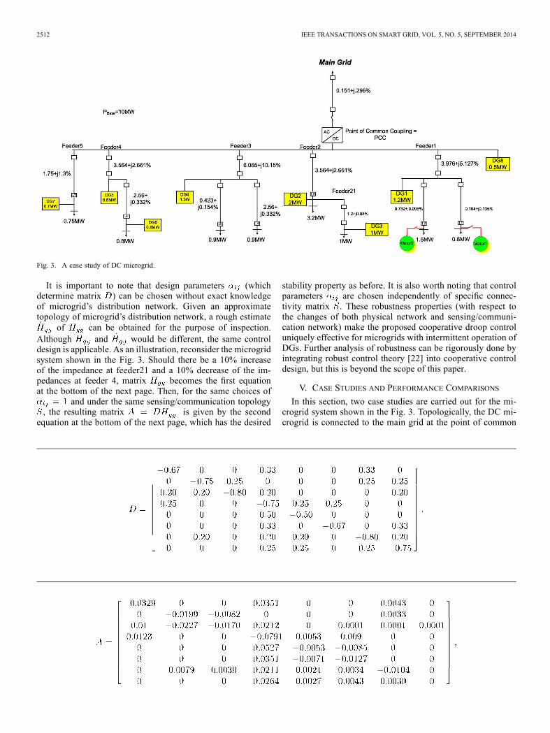
Fig. 3. The microgrid has eight DGs, and its physical topologyand line resistances yield the admittance matrix at the bottomof the page. Suppose that the sensing/communication networkamong the DGs is represented by
(16)
Then, the simplest choices of for all and rendersmatrix as the first equation at the bottom of the next page.It is straightforward to verify that is given by the
second equation at the bottom of the next page, which has thedesired stability property but is not a Metzler matrix.
2512 IEEE TRANSACTIONS ON SMART GRID, VOL. 5, NO. 5, SEPTEMBER 2014
Fig. 3. A case study of DC microgrid.
It is important to note that design parameters (whichdetermine matrix ) can be chosen without exact knowledgeof microgrid’s distribution network. Given an approximatetopology of microgrid’s distribution network, a rough estimate
of can be obtained for the purpose of inspection.Although and would be different, the same controldesign is applicable. As an illustration, reconsider the microgridsystem shown in the Fig. 3. Should there be a 10% increaseof the impedance at feeder21 and a 10% decrease of the im-pedances at feeder 4, matrix becomes the first equationat the bottom of the next page. Then, for the same choices of
and under the same sensing/communication topology, the resulting matrix is given by the secondequation at the bottom of the next page, which has the desired
stability property as before. It is also worth noting that controlparameters are chosen independently of specific connec-tivity matrix . These robustness properties (with respect tothe changes of both physical network and sensing/communi-cation network) make the proposed cooperative droop controluniquely effective for microgrids with intermittent operation ofDGs. Further analysis of robustness can be rigorously done byintegrating robust control theory [22] into cooperative controldesign, but this is beyond the scope of this paper.
V. CASE STUDIES AND PERFORMANCE COMPARISONS
In this section, two case studies are carried out for the mi-crogrid system shown in the Fig. 3. Topologically, the DC mi-crogrid is connected to the main grid at the point of common

MAKNOUNINEJAD et al.: OPTIMAL, NONLINEAR, AND DISTRIBUTED DESIGNS OF DROOP CONTROLS FOR DC MICROGRIDS 2513
coupling and through the AC/DC converter at the top. The con-verter is to maintain a grid-tied operation and meet the demandof all the loads by converting the grid AC voltage into a DCone, suitable for the DC microgrid operation. There are a totalof eight DGs distributed across the microgrid, and they have atotal of 15.5 MVA generation capacity. In particular, it is as-sumed that DGs 2, 3 and 4 are wind farms and that DGs 1, 5, 6,7, and 8 are solar farms.Two operational scenarios are simulated to compare the per-
formance of conventional droop control (10) and the proposedcooperative droop control (12). For the conventional droop, itsdroop gains are chosen based on the Fig. 2; specifically in (10)together with (2), the gain is chosen asif p.u. or if p.u.,where and are the rated capacity of generation andstorage, respectively. In the first scenario, DGs are operating at50% of their rated capacity. In the second scenario, DGs’ avail-able power are determined by their profiles in the Fig. 7. Foreach DG, per unit is based on its own capacity and not the micro-grid power base; e.g., in Fig. 7, DG1 has 1 p.u. power availableor 1.2 MW power available, based on its rated capacity shownin Fig. 3. For cooperative adaptive droop control (14), designgains are chosen as for all . It is assumedthat the sensing/communication topology is given by (16).As the first operational scenario, the DGs are connected to
the system at . Afterwards, a 300 KW DC motor isconnected to the feeder1 at , which causes a transientvoltage dip in the microgrid. The two control options, eitherconventional droop control (10) and the proposed cooperativedroop control (12), are implemented at the DGs to regulate theirnode voltages. Figs. 4 and 5 show the voltages at DG3 and DG6,similar changes are observed at all other DG nodes, and Fig. 6provides the norm of the voltage deviations from unity at theseDG nodes. In these three figures, the conventional droop control
Fig. 4. Voltage of DG3.
Fig. 5. Voltage of DG6.
and the proposed cooperative droop control are compared, andit is apparent that the cooperative droop control has a superiorperformance.

2514 IEEE TRANSACTIONS ON SMART GRID, VOL. 5, NO. 5, SEPTEMBER 2014
Fig. 6. Norm of voltage derivations from unity.
Fig. 7. Profile of DGs.
Fig. 8. Voltage of DG3 in a daily operation.
As the second case study, a typical daily operation of the mi-crogrid is simulated to evaluate its performance. The daily gen-eration profiles of the DGs are provided in Fig. 7, and the sim-ulation is for the time period from 9:00 am to 6:00 pm. Figs. 8and 9 contain the voltages at DG3 and DG6, respectively; andFig. 10 presents the norm of the voltage errors from unity at theDGs across the microgrid. Better voltage regulation is achievedby the proposed cooperative droop control. Fig. 11 shows theactive power losses of the microgrid. It is noticed that the activepower losses have been reduced by two thirds, or about 200 KW,
Fig. 9. Voltage of DG6 in a daily operation.
Fig. 10. Norm of voltage deviations from unity in a daily operation.
Fig. 11. Norm of voltage deviations from unity in a daily operation.
when compared with the conventional droop. This loss reduc-tion amounts to 2% of the overall power rating of the microgridunder study, which is significant practically and theoretically.Intuitively, cooperative droop control achieves better perfor-
mance through locally sharing information among the neigh-boring nodes, and it approaches the optimal control if the infor-mation is shared across the microgrid. Simulation studies alsoshow that the proposed control is robust with respect to thechanges of both the physical grid and the (local) sensing/com-munication network(s).
MAKNOUNINEJAD et al.: OPTIMAL, NONLINEAR, AND DISTRIBUTED DESIGNS OF DROOP CONTROLS FOR DC MICROGRIDS 2515
VI. CONCLUSION
In this paper, advanced droop controls are designed, analyzedand compared for a DC microgrid with intermittent operationof DGs. First, an optimal control is designed for voltage/powerregulation in the microgrid. The resulting control is nonlinearbut can be approximated by a linear near-optimal control, andthese controls require the full knowledge about the microgrid. Itis shown that, if each DG operates by itself, the linear near-op-timal control without any information about other nodes reducesto the conventional droop control as well as an adaptive con-trol with a small leakage. Given that smart microgrids wouldhave (intermittent) communication links to locally exchange in-formation, a cooperative droop control is proposed to take ad-vantage of the information distributively available. Stability andperformance of the distributed cooperative droop control are an-alyzed to show that it includes the conventional droop control asa special case, provides the superior performance, and is robustwith respect to the changes of distribution network and commu-nication network.
APPENDIX APROOF OF THEOREM 1
Let and be the (feasible) solution to the followingalgebraic equations:
.(17)
It follows from (3) and (17) that, for ,
(18)
and, for ,
On the other hand, it follows from linear quadratic optimalcontrol theory [23] that, under performance index (of suffi-ciently large )
the optimal steady-state tracker for system (2) is given by
(19)
(20)
Substituting (18) into (20) yields control (5). Under control (19),system (2) becomes
which is exponentially stable with respect to the steady state
This completes the proof.APPENDIX B
PROOF OF LEMMA 1
It follows from (3) and (1) that, for constant-resistance loads,, where is the diagonal matrix
consisting of , , and ,where if and if . It followsthat, for any reasonable steady state and ,
(21)
where matrix is defined by
ifif .
(22)
It follows from [18] that is a symmetric, nonsingular M-ma-trix.Let be the permutation matrix such that ,
where for . It follows that, where for . Applying matrix
to (21) and then partitioning the resulting matrix yield
...
...
Solving the above equation renders relationship (15) betweenand , where . Again, it can be
shown that reduced-order matrix is a symmetric, nonsin-gular M-matrix. Hence, its inverse is a positive matrix, and rel-ative values of off-diagonal entries are monotonely increasingfunctions of the distances among the DGs.
APPENDIX CPROOF OF THEOREM 2
It follows from system (2) and cooperative droop control (12)that, among all possible steady-state solutions and ,
(23)where is the vector of 1s, and. Hence, the specific steady state achieved under cooperative
droop control (12) satisfies the relationship of , that is,
(24)
where the last equation comes from the fact that has zero rowsums.For the steady state satisfying (24), one can substituting (15)
into (23) and obtain
Asymptotic stability and local exponential convergence can beconcluded using Lyapunov function matrix .

2516 IEEE TRANSACTIONS ON SMART GRID, VOL. 5, NO. 5, SEPTEMBER 2014
Recall that cooperative droop control (12) includes the twoextreme cases: conventional droop control (10) if is the iden-tity matrix and, if , near-optimal control (9) corre-sponding to for . It follows from theorem 1and from the discussions of (7), (8) and (9) that, as cooperativedroop control (12) has more information, it becomes closer tonear-optimal control (9) and hence the node voltages becomecloser to 1.
REFERENCES
[1] M. E. Baran and N. R. Mahajan, “DC distribution for industrial sys-tems: Opportunities and challenges,” IEEE Trans. Ind. Appl., vol. 39,no. 6, pp. 1596–1601, Nov. 2003.
[2] A. Maknouninejad, W. Lin, H. G. Harno, Z. Qu, and M. A. Simaan,“Cooperative control for self-organizing microgrids and game strate-gies for optimal dispatch of distributed renewable generations,” EnergySyst., vol. 3, no. 1, pp. 23–60, 2012.
[3] H. Ikebe, “Power systems for telecommunications in the IT age,” inProc. IEEE INTELEC, Yokohama, Japan, Oct. 2003.
[4] A. Kwasinski and C. N. Onwuchekwa, “Quantitative evaluation of dcmicrogrids availability: Effects of system architecture and convertertopology design choices,” IEEE Trans. Power Electron., no. 3, pp.835–851, Mar. 2011.
[5] D. Nilsson and A. Sannino, “Efficiency analysis of low- and medium-voltage dc distribution systems,” in Proc. IEEE PESGen. Meet., Wash-ington, DC, USA, Jun. 2004, vol. 2, pp. 2315–2321.
[6] G. S. Seo, J. Baek, K. Choi, H. Bae, and B. Cho, “Modeling and anal-ysis of dc distribution systems,” in Proc. 8th Int. Conf. Power Electron.—ECCE Asia, The Shilla Jeju, Korea, May 2011, vol. 2, pp. 223–227.
[7] E.W. Kimbark, “DC transmission,”Direct Current Transm., vol. 1, no.6, pp. 148–152, Nov. 1971.
[8] H. Kakigano, Y. Miura, T. Ise, and R. Uchida, “Dc micro-grid forsuper high quality distribution-system configuration and control of dis-tributed generations and energy storage devices,” in Proc. IEEE PowerElectron. Specialists Conf., Washington, DC, USA, Jun. 2006, pp. 1–7.
[9] G. Byeon, T. Yoon, S. Oh, and G. Jang, “Energy management strategyof the dc distribution system in buildings using the ev service model,”IEEE Trans. Power Electron., vol. 28, no. 4, pp. 1544–1554, Apr. 2013.
[10] F. Katiraei and M. Iravani, “Power management strategies for a micro-grid with multiple distributed generation units,” IEEE Trans. PowerSyst., vol. 21, no. 4, pp. 1821–1831, Nov. 2006.
[11] F. Katiraei, R. Iravani, N. Hatziargyriou, and A. Dimeas, “Microgridsmanagement,” IEEE Power Energy Mag., vol. 6, no. 3, pp. 54–65,2008.
[12] F. Katiraei, M. Iravani, and P. Lehn, “Small-signal dynamics modelof a micro-grid including conventional and electronically interfaceddistributed resources,” IET Gener., Transm., Distrib., vol. 1, no. 3, pp.369–378, May 2007.
[13] M. Prodanovic and T. Green, “High-quality power generation throughdistributed control of a power park microgrid,” IEEE Trans. PowerDel., vol. 53, no. 5, pp. 1471–1482, Oct. 2006.
[14] Y. Abdel-Rady, I. Mohamed, and E. F. El-Saadany, “Adaptive decen-tralized droop controller to preserve power sharing stability of par-alleled inverters in distributed generation microgrids,” IEEE Trans.Power Electron., vol. 23, no. 6, pp. 2806–2816, Nov. 2008.
[15] J. C. Vasquez, J. M. Guerrero, A. Luna, P. Rodriguez, and R. Teodor-escu, “Adaptive droop control applied to voltage-source inverters op-erating in grid-connected and islanded modes,” IEEE Trans. Ind. Elec-tron., vol. 56, no. 10, pp. 4088–4096, Oct. 2009.
[16] H. Alatrash, A. Mensah, E. Mark, G. Haddad, and J. Enslin, “Gener-ator emulation controls for photovoltaic inverters,” IEEE Trans. SmartGrid, vol. 3, no. 2, pp. 996–1011, Jun. 2012.
[17] J. M. Guerrero, J. C. Vasquez, J. Matas, L. G. de Vicuna, and M.Castilla, “Hierarchical control of droop-controlled ac and dc micro-grids—A general approach toward standardization,” IEEE Trans. Ind.Electron., vol. 58, no. 1, pp. 158–172, Jan. 2011.
[18] Z. Qu, Cooperative Control of Dynamical Systems. London, U.K.:Springer, 2009.
[19] H. Xin, Z. Qu, J. Seuss, and A. Maknouninejad, “A self-organizingstrategy for power flow control of photovoltaic generators in a distribu-tion network,” IEEE Trans. Power Syst., vol. 26, no. 3, pp. 1462–1473,2011.
[20] A. Maknouninejad, Z. Qu, J. Enslin, and N. Kutkut, “Clustering andcooperative control of distributed generators for maintaining micro-grid unified voltage profile and complex power control,” in IEEE PESTransm. Distrib. Conf., Orlando, FL, USA, May 2012, pp. 1–8.
[21] K. S. Narendra and A. M. Annaswamy, Stable Adaptive Systems.Englewood Cliffs, NJ, USA: Prentice-Hall, 1989.
[22] Z. Qu, Robust Control of Nonlinear Uncertain Systems. New York:Wiley, 1998.
[23] F. L. Lewis, Optimal Control. New York: Wiley, 1986.
Ali Maknouninejad (S’08–M’13) received hiselectrical engineering B.Sc from University ofTehran, Tehran, Iran, in 2001. Then, he joined PowerSupply Production (PSP) Co., Tehran, as a ResearchEngineer and worked on the design and constructionof DC/AC inverter converters up to 30 KVA for usein UPS systems. He attended University of CentralFlorida (UCF), Orlando, FL, USA, in 2008, receivedhis M.Sc. in Electrical Engineering in 2010, andthen completed his Ph.D. study in May 2013. Hisresearch interests include smart grid and distributed
generator control and stability analysis.
Zhihua Qu (M’90–SM’93–F’09) received the Ph.D.degree in electrical engineering from the GeorgiaInstitute of Technology, Atlanta, GA, USA, in June1990. Since then, he has been with the Universityof Central Florida (UCF), Orlando, FL, USA. Cur-rently, he is the SAIC Endowed Professor in Collegeof Engineering and Computer Science, Professor andChair of Electrical and Computer Engineering, andthe Director of FEEDER Center (one of DoE-fundednational centers on distributed technologies andsmart grid). His areas of expertise are nonlinear
systems and control, with applications to energy and power systems. In energysystems, his research covers such subjects as low-speed power generation,dynamic stability of distributed power systems, anti-islanding control andprotection, distributed generation and load sharing control, distributed VARcompensation, distributed optimization, and cooperative control.Dr. Qu iscurrently serving as an Associate Editor for Automatica and IEEE Access.
Frank L. Lewis (S’78–M’81–SM’86–F’94)received the B.S. degree in physics/electricalengineering and the M.S.E.E. degree from RiceUniversity, Houston, TX, USA, the M.S. degree inaeronautical engineering from the University of WestFlorida, Pensacola, FL, USA, and the Ph.D. degreefrom the Georgia Institute of Technology, Atlanta,GA, USA. He is a Distinguished Scholar Professorand Moncrief-O’Donnell Chair with the Automationand Robotics Research Institute (ARRI), Universityof Texas at Arlington (UTA), TX, USA. He works
in feedback control, intelligent systems, distributed control systems, andsensor networks. Dr. Lewis is also a Fellow of the International Federation ofAutomatic Control (IFAC) and a Fellow of the U.K. Institute of Measurementand Control. He is a Professional Engineer in the state of Texas and a CharteredEngineer in the U.K.
Ali Davoudi (S’04–M’11) received his Ph.D. inElectrical and Computer Engineering from theUniversity of Illinois, Urbana-Champaign, USA,in 2010. He received B.Sc. and M.Sc. degrees inElectrical and Computer Engineering from SharifUniversity of Technology, Tehran, Iran, and TheUniversity of British Columbia, Vancouver, Canada,in 2003 and 2005, respectively. He is currently anAssistant Professor at the Electrical EngineeringDepartment, University of Texas, Arlington, TX,USA. He worked for Solar Bridge Technologies,
Texas Instruments Inc., and Royal Philips Electronics. He is an AssociateEditor for IEEE TRANSACTIONS ON INDUSTRY APPLICATIONS. His researchinterests are various aspects of modeling, simulation, and control of powerelectronics, energy conversion systems, and finite-inertia power systems.