25.03 - Drenth Motorsport Gearboxes · This document contains information about the Drenth display...
21
25.03.0023
Transcript of 25.03 - Drenth Motorsport Gearboxes · This document contains information about the Drenth display...
25.03.0023

2 Manual Display
unit
Drenth Motorsport Gearboxes Fleuweweg 10 7468 AG Enter The Netherlands Phone: +31 (0)547 38 26 96
Fax: +31 (0)547 38 20 65 Last modified: December 2012 [email protected] Made by Arjan Hoogendijk www.drenth-gearboxes.com
Introduction
The display unit comes with a software application. With the software application information shown on the display can be adjusted. There are different
modes to adjust: the shape of the RPM indication and the duration of the engine cut can be controlled (power-shift). Beside this the gear indicator also gives
information about which gear is selected. The settings of the DMS gearlever can also be calibrated with the display unit.
This document contains information about the Drenth display unit. The user manual includes function descriptions, wiring diagrams and instructions to use the software that is included.

3 Manual Display
unit
Function description
The Advanced Display unit, which Drenth can supply, has the following options:
Mounting display unit For mounting the display unit, use the M5 threads on the backside of the display unit.
See picture on the right for centre distance.
Warning: Do not use glue on the RVS plate on the back!
Gearindication:
The gear indicator displays the selected gear by measuring the position of the selector barrel with a rotary sensor. This function can be calibrated through the supplied software.
Shiftlight
The gear indicator can be used as a shiftlight when a preset level of RPM is reached. This preset level and the manner of indicating can be set with the
supplied software.
Flatshift The gear indicator can act as a flatshift system (powershift) This means that you can accelerate (full throttle) and shift up without using the clutch or lifting
the throttle. The gear indicator provides a signal that can be used to make a engine cut for powershifting. It is possible to set different cut times in several
gears with the supplied software.
Throttle blip or reverse light With the supplied software there is the possibility to use the reverse light or the throttle blip. The throttle blip time can be adjusted for all the different gears
separately in milliseconds. the use of a throttle blip gives the possibility for a smoother downshift.
Set-up DMS Gearlever
The set-up of the DMS Gearlever can be calibrated to your own specifications. The force which is needed to shift up and shift down can be adjusted in the loadcell. It’s possible to use flat shifting for up shift and throttle-blip or the clutch for downshift.
This manual describes the different options on how to use them.

4 Manual Display
unit
Connections
1. Power is supplied to the red (12 volt) and black wire (ground). So it doesn’t matter which red wire is connected to the relay or the +12V because they are
internal connected. The maximum voltage of the supply is 17-volt, the minimum is 9 volt. Make sure that the supply is free of interference (do not connect to ignition coil or starter). The ground must be directly connected to engine ground, do not place a switch in this wire. Disconnecting ground when the display is
on can lead to permanent damage!
2. For the RPM pickup the gear indicator comes with 2 wires. You can use either one (not both) depending on car electronics and wire loom. We advise to
start with the green wire as this can handle 1700 volts maximum. Connect the green wire to the negative side of the ignition coil. Otherwise use the pink wire to connect to the coil driver’s (of the ignition system). Note that it can only handle 15 volts maximum. If this wire is overloaded the display unit is damaged.
3. The wires to connect the power shift are the yellow/black (signal) and white/black (ground). They must be connected to the switch that is mounted in the
gearbox. It is actuated when the gearbox shifts up, the type of switch NO (Normally Open) or NC (Normally Closed) can be set in the software. Make sure
that the switch is isolated from the gearbox.
4. Gear position wires are black/grey (ground), yellow/green (5 volts) and grey/blue for the signal. These go to the rotary sensor as follows:
Cable display Function Cable rotary sensor
Black / grey Ground Black
Yellow / green 5 Volts Red
Grey / blue Signal Depends on which
gearbox is used
Gearbox: Signal wire:
Evo IX Sequential Yellow
EVO X sequential Yellow
DG 400 White
DG 500 White
Evo Sequential Unit (38.07.xxxx) White
MPG White

5 Manual Display
unit
View rotary sensor: When shifting up, the shaft of the rotary sensor turns in the direction of the arrow.
Wire: Yellow (CW) Wire: White (CCW)
Voltage + Voltage +
Voltage - Voltage -
5. Relay wires are the orange (switched ground) and red (12 volt). Connect these to the coil of the relay. The switch of the relay is placed in the supply line to
the ignition coil.
6. If the reverse is engaged the purple wire is connected to ground. Please note that the maximum load for the wire is 12 watt. This signal can be used for a reverse light.
7. The connector strain from the gearlever differences from 2012 and 2013. In the table below is an overview of the cable colours of the connecter strains from the gearlever and the connector from the gauge to the gearlever.
Gearlever 2012 Gearlever 2013 Function Connector display
Yellow Brown +5Volt Red
Black Black Ground Bleu
Gray Bleu Signal Green

6 Manual Display
unit
Figure 2:
Connection diagram
Wiring diagram for engines with a standard coil
Figure 1:
Wiring diagram engines standard coil
The control wire form the ecu needs to be connected through
with the wire that goes to the relay, so the wire does not get
interrupted when the flatshift is used. This needs to be done
because if the coil gets interrupted the ecu can switch to
emergency mode.
It is important that the relay is a fast
switching relay. If a wrong relay is
used it will result in a delayed cut time.
Use the supplied relay.

7 Manual Display
unit
Wiring diagram for engines with a built-in coil driver
The control wire form the ecu needs to be connected through
with the wire that goes to the relay, so the wire does not get
interrupted when the flatshift is used. This needs to be done
because if the coil gets interrupted the ecu can switch to
emergency mode.
Figure 2: Wiring diagram engines with a built-in
coil driver
It is important that the
relay is a fast switching
relay. If a wrong relay is
used it will result in a
delayed cut time. Use the
supplied relay.

8 Manual Display
unit
Wiring Diagram for the use of a throttle blip with a solenoid
The Drenth Display Unit can be used to control a throttle blip. When a
solenoid is used to open the throttle, then the display must be
connected as shown in figure 3. A fast switching relay is used to switch
the solenoid.
When the throttle is controlled by an digital drive by wire system, the
purple wire can be used as a signal pickup for a throttle blip.
It is important that the relay is a fast
switching relay. If a wrong relay is
used it will result in a delayed Throttle
blip. Use the supplied relay.
Figure 3: Wiring diagram throttle blip with a
solenoid

9 Manual Display
unit
Wiring Diagram model before 2017
Models delivered before 2017 have white/black and yellow/black cables instead of white and black cables for the Powershift switch.
The control wire form the ecu needs to be connected
through with the wire that goes to the relay, so the wire
does not get interrupted when the flatshift is used. This
needs to be done because if the coil gets interrupted the
ecu can switch to emergency mode.
It is important that the relay is a fast
switching relay. If a wrong relay is
used it will result in a delayed cut
time. Use the supplied relay.
Figure 4: Wiring diagram engines standard coil
before 2017

10 Manual Display
unit
Software functions
1. Load settings from file Opens a dialog box where you can open a “saved settings” file.
2. Save settings to file Opens a dialog box to save the settings that are currently set up in the software.
3. Transmit settings to display
Sends the settings that are currently on your screen to the display unit.
4. Receive settings from display
Reads the settings that are in the display unit. It’s important to do this first. The software will always start with the default setting, for example if you only change the shift light and then select [transmit settings to display] the setting of the default file with the changed shift light values will be sent to
your display.
5. RPM Pickup – ignition coil type
In this box you can set what type of coil is used. It is important to fill it in correctly; it is not only used for the shift light but also for the power shift. The power shift only works above 3000 rpm, this will allow engagement of first gear without stopping the engine.
6. Switch type With the box [switch type] you can select the type of switch that is used to generate engine cut.
-Normaly closed:
Normaly closed means if the switch on the gearbox is actuated the circuit will be interrupted.
-Normaly open:
Normaly open is standard in a Drenth gearbox, this means if the switch on the gearbox is actuated the circuit will be closed.
11 Manual Display
unit
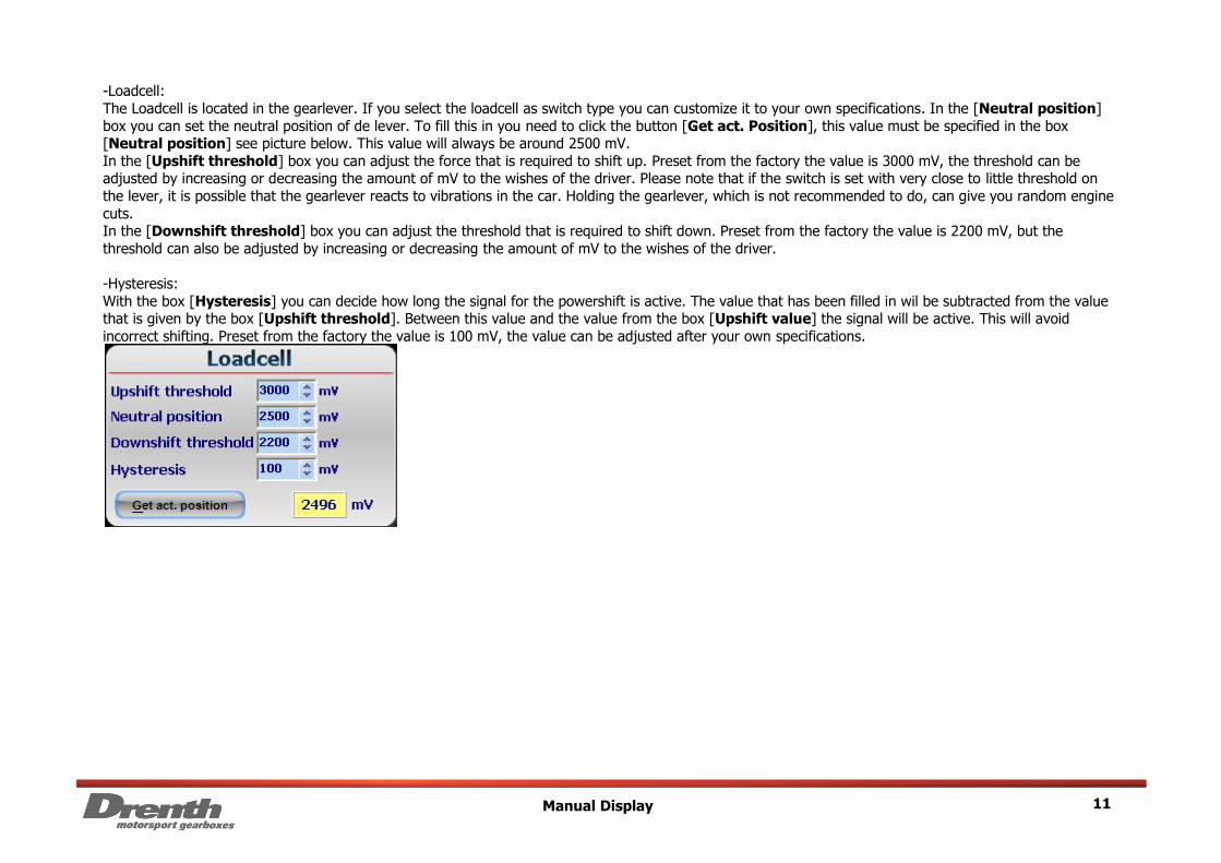
-Loadcell:
The Loadcell is located in the gearlever. If you select the loadcell as switch type you can customize it to your own specifications. In the [Neutral position]
box you can set the neutral position of de lever. To fill this in you need to click the button [Get act. Position], this value must be specified in the box [Neutral position] see picture below. This value will always be around 2500 mV.
In the [Upshift threshold] box you can adjust the force that is required to shift up. Preset from the factory the value is 3000 mV, the threshold can be adjusted by increasing or decreasing the amount of mV to the wishes of the driver. Please note that if the switch is set with very close to little threshold on
the lever, it is possible that the gearlever reacts to vibrations in the car. Holding the gearlever, which is not recommended to do, can give you random engine
cuts. In the [Downshift threshold] box you can adjust the threshold that is required to shift down. Preset from the factory the value is 2200 mV, but the
threshold can also be adjusted by increasing or decreasing the amount of mV to the wishes of the driver.
-Hysteresis:
With the box [Hysteresis] you can decide how long the signal for the powershift is active. The value that has been filled in wil be subtracted from the value that is given by the box [Upshift threshold]. Between this value and the value from the box [Upshift value] the signal will be active. This will avoid
incorrect shifting. Preset from the factory the value is 100 mV, the value can be adjusted after your own specifications.

12 Manual Display
unit
7. Advanced setting – cut times
With the box [Cut time] you can set the time that the relay is active. The time that is needed depends on the type of engine and ratio’s in the gearbox.
To reverse the signal that is going to the relay, you can select the box [Invert output]. You can determine whether the relay stays open or stays closed.
The delay time is the time to wait for the cut time. Please leave the delay time set to nil as this is only used on recommendation of Drenth.
The cut time is the time that the ignition is paused.
To use the advanced settings, first select [Use advanced settings] (tick box) and then select [Advanced settings].
With the box [Min RPM for cut and blib time] you can set the minimum RPM that must be reached to provided an engine cut or throttle blip.
With the box [Switch debounce time] you can set the minimum time that the switch in the gearbox needs to be activated for a useful signal.
With the box [Pause between shift] you can set the time that you need to wait to shift for the next time. This will avoid accidentally shifting down or up
several times short after each other.
With the boxes [Blip time] you can set for several gears the time that the purple wire is switched to ground, for example for throttle blip.

13 Manual Display
unit

14 Manual Display
unit
8.Shiftlight In this box the shift light rpm and mode can be set. With the slide bar in this box it is possible to see a demo of the different modes in the display box.
The 4 different modes available are:
- Mode 0: On the set level the gear display will change to a completely filled flashing display.
- Mode 1: On the set level the gear display will change to a completely filled display without flashing.
- Mode 2: 900 rpm before the set level the display is emptied and will then be filled bottom row first, then upwards until the display is completely filled.
- Mode 3: 900 rpm before the set level the display is emptied and will then be filled bottom row first, then upwards until the display is completely filled.
The display is flashing when it’s being filled upwards.
9. Output 2 In this box the function of the purple wire can be set. The different possibilities are:
- Reverselight: The purple wire can be used for the reverse light
- Blip: If this is selected the purple wire can be used for switching the throttle blip.
- No function (high): The purple wire has no function.

15 Manual Display
unit
10. Default
If this button is used the software will load the file {default.drg} and delete the settings that are on your screen.
11. Automatic Cal. With this button the rotary sensor that is mounted in the gearbox can be calibrated. After pressing the button [Automatic Cal.] a dialog box will open and
you will be asked to put it in reverse gear, at the same time the display will show a [p]. When the gear is selected click on the [ok] button. Repeat until the
last gear is done. When you rebuild the gearbox it is recommended to check this first, because the position of the rotary sensor is difficult to change when the gearbox is mounted in the car.

16 Manual Display
unit
12. Rotary sensor
First make sure that the rotary sensor is mounted in the right position, on the ridge of the potentiometer there’s a small notch. Make sure the ridge is standing vertical with the notch facing downwards and the cable needs to go up. Before mounting make sure the gearbox is in reverse.
For a detailed graphic see figure below.
When this message appears there are two things you need to check. When the voltage is not correct with the rotation direction you need to check the colour of the signal wire, see page 4 and 5. If the voltage starts at 2,5 Volts instead of starting at 0 Volts you need to turn the rotary sensor 180 degrees.

17 Manual Display
unit
13. Manual Calibration
With this function you can do the manual calibration.
The values must increase otherwise the display will show an incorrect value. If the rotary sensor gives a voltage that is between two gear positions the
display will show [x] to show you the gearbox is not properly engaged. You can measure the voltage from the rotary sensor on signal wire to determine right value.

18 Manual Display
unit
14. Display brightness
With this function you can set the brightness of the display. The [automatic]
selection only works on displays with a day light sensor, which is located on the front of the display.
15. Number of gear positions
With the [on/off] setting you can set how many gear positions are used, it is important to set this correctly. The function [Automatic Cal.] uses these values to see how many gear positions there are, and if not set correctly [Automatic Cal.] it will not function.
With [display text] you can set in which order and how many gears there are.
19 Manual Display
unit
Setting up for powershifting
This is a brief description about adjusting the power shift system. If you make use of the switch you need to adjust it first. Then you can setup the cut time via the supplied software. Depending on the type of gearbox delivered from Drenth, there is an external switch mounted on the gearbox or Drenth can supply
a strain gauge gearlever. This switch or gearlever detects an up shift. When an up shift is detected the controller cuts of the ignition by the programmed
amount of time.
External Switch The external switch comes preset from the factory. For the switch please check if it is set correctly. Use a multimeter to determine if the switch is closed.
When you are up shifting the switch should close when all the play in the selection system is pushed out. You will feel an increase of force needed to pull the
lever. This is when the switch should be closed. You can adjust it via the shims supplied with the power shift switch.
Strain Gauge Gearlever The strain gauge gearlever comes preset from the factory. The gearlever has an analogue output, this output contains three wires (yellow, black and grey).
Yellow contains 5 Volts, black contains ground and grey is the analogue readout. When the gearlever is in neutral position it sends out 2,5 Volts. By pulling the gearlever the voltage will increase and by pushing the gearlever the voltage will decrease.
For more detailed information on the strain gauge gearlever please see the manual for the strain gauge gearlever.
Test the RPM pickup
Set the shift light to 2000 rpm mode 0. If it starts at a different rpm, the software may be set up incorrectly. If it does not work, there might not be a rpm-signal pickup. Please check all the connections and the pink / green wire like mentioned on page 4.
Cut times We recommend that you drive the car first with no power shift and use the clutch with up- and downshifting. When you pull the gear lever make sure that
you make a full stroke, pull convinced. Then try to shift up without use of the clutch and lift your foot off the throttle. Notice that the shifting with the gear lever should go just as easily as it would when using the clutch. First try to flat shift using the default values (cut time for each gear 100 ms). You will feel a
difference when selecting gears. Some will feel like shifting with a clutch, but the most will feel “stiffer” or more harsh. After that there can be started with
the fine tuning, notice that how higher the gear ratio how higher the shift times has to be. If you have achieved to find an optimum setting for the gear’s 2 till 5, then we recommend to use advanced settings.
Set the cut time for each gear independently at the recent found settings. Then lengthen the time for the lower gears, and shorten the time for the higher gears. The cut time will vary between 120 –45 ms. If it’s too long or to short it won’t shift with the same feeling as when using the clutch. Note that a
properly setup power shift system, can reduce wear on the gearbox. Also a not very accurate setting can cause damage!
Delay times
The delay time is the time to wait for the cut time. Please leave the delay time set to nil as this is only used on recommendation from Drenth.

20 Manual Display
unit
Contact Information
Address
Drenth Motorsport Gearboxes Fleuweweg 10
7468 AG Enter
The Netherlands Phone: +31 (0)547 38 26 96
Fax: +31 (0)547 38 20 65 www.drenth-gearboxes.com
Contact Persons
Sales department:
Johan Drenth
Engineering:
Jeroen Grolleman

21 Manual Display
unit