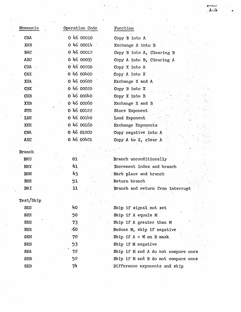
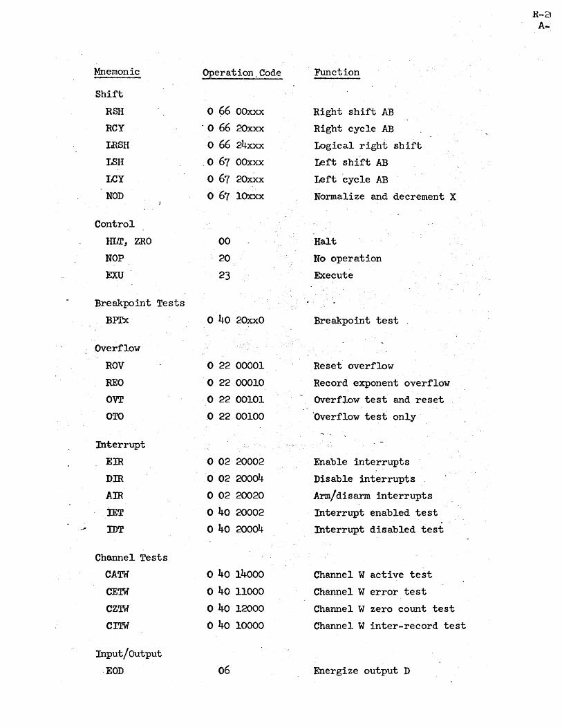
24, · SKB SKD Operation Code o 46 00010 o 46 00014 o 46 0001'2 o 46 00005 o 46 00200 o 46 00400 o...
96
ARPAS REFERENCE MANUAL FOR TlME SHARING ASSEMBLER FOR SDS.930 Document No. R-26 Revised February 24,.1967 Contract SD-l85 Office of Secretary of Defense Advanced Research Projects Agency Washington 25, D. C•
Transcript of 24, · SKB SKD Operation Code o 46 00010 o 46 00014 o 46 0001'2 o 46 00005 o 46 00200 o 46 00400 o...

ARPAS
REFERENCE MANUAL FOR TlME SHARING
ASSEMBLER FOR SDS.930
Document No. R-26
Revised February 24,.1967
Contract SD-l85
Office of Secretary of Defense
Advanced Research Projects Agency
Washington 25, D. C •

.1.0
2.0
3.0
.4.0
5·0 6.0
T~LE OF CONTENTS
Introduction • • ... . . . . . . .. .. . . . • • 1-1 1.1
1.2
1.3'
1.4 1.5 1.6 1.7 1.8
Basic Description or the Assembler
Symbols ••• · . . .. • 1-1.
1-1
Instructions, Directives, and Comments " .•• 1~2
Subprograms • • • • • • • • • • • · ~ . . Literals
Relocation
e.. • • •• · .. · .. -.. ' .. ~
· . . . . .. .'
· . . . • •
. .. Basic Assembly Procedure
Notation • • • • • • •• • • ..... · . . . . . · . . · . . · ... · . . .. e· •
1-2
1-2
1-2
1-3,
1-4 The Assembly Language
2.1 Charecter Set · . . · ..... . • .' ••• 2-1 2.2 Statements · . . · .". .. . 2-1
2.3 Programs ••••• · . . ". · . . 2-3 The Syntax of Instructions •
3.1 Their Classification · . . · . . . . . · •• 3-1
Use of the Label Fie1d
Operand Field • • • • · . .
· . . .'''; .
3-1
3-2
3-2
Alternate Conventions for Expressing Indexed and Indirect Addresses • · . . . . • • 3':'2
3-3
4-1 Comment Field
Expression Syntax
4.1 Operators
.. . . . .. ... . .. . . . · .,. ,... . . . . · . . . · . .
4.2 4.3 4.4 4.5 4.6
· . . . . . .'. · . . .. . . .. . . . Constants . · • . ·0 .. . . .... . . .'. . . . . . Classification of Symbols. • · . . . . . . .. Terms .' . . . . . • • e_ • • •
Expressions • • • •••.• • • • • · . . Constraints of Relocatability of Expressions · . .
4.7 Special Relocation · . . · . . -Literals . . · · · · .. · ~ .. · • · · • · · Directives . · · · · · • · • · · · . · • · 6.1 COpy Generalized Register Change Command
6.2 DATA Generate Data • · · . · · · · · · · 6.3 TEXT Generate Text · · · · • · ·0 · · · • · 6.4 ASC Generate Text with Three Characters per Word · 6.5 EQ.U Equals · · · · · · · · · · · · · • · · . • · ·
4-1 4-2 4 ... 2
4:"3
4-4 4-4 4-5 5-1 6 ... 1
6-2 6-3 6-3 6-4 6-4
R-26

6.6 EXT Define External Symbol • • • • ~ • • e. _. ~ ..• • .•. _. 6-5 6.7 NARG Equate Symbol to Numbe~ of Arguments
in Macro Call . • • _ • • • • • • • .'~: • •
6.8 NCHR Equate Symbol to· the Number of Characters in Operand • • • • • • •• • • 6-6
6.9 OPD Operation Code Definition ••• -. '.:r~· • ...• 6-7
6.10 PqPD Progranuned Operator Definition • '."" -Y;<. • 6-7 .6.11 BES .-Block Ending Symbol. ~ • • • • • • • ,; ...... ' .• 6-8
6.12 BSS Block Starting Symbol • • • .'. .'.. • • • .' -. q. 6-9
6.13 ORG Program Origin • • • .• • • '. .• • • • .: 6-9
_ .6.14 END End of Assembly • • • • • • • • •.• • • • • •• 6-9 _ . 6,.15 pEe Interpret Integers as Decimal
i .~ • .-
", ,p.16 OCT: Interpret. Integers as Octal,-
, . ,6.?-7. RAJ) Set Special Relocation Radix
6.18 FR~T Forget Name of Symbol
. .. . - :
· . '. .. ' . .
6-10
6-10
6-10 6;,.11
• .• 6-11 . -' 6.19 IDENT Program :Identification . • • ••
..,~.20 DELSYM Delete Output 'of Symbol Table and Defined Op-codes ••.• • • -.. • -, •. ,e. • • • '>~ 6-12
~"_6.21 RELORG 'Assemble Relative with .Absolute 6~i~i~ ' ••• 6-12
, '''6.22 RETREL Return- to Relocatabl~ Assembly, • • • • • • • 6-13 '-.~: 6.23 FREEZE Preserve Symbols, Op-codes, and Macros - • 6-14'
;. ,/ 6.24 NOEXT Do Not -Create External Symbols ••.•• • 6-15 :. /~6.25 LIST' Turn Specified Listing Controls 'On •••••• '6-15
, '
. -->·6.26 NOLIST ~n Specified Listing Cont:rols Off _ -. '
· -6~27' PAGE Begin New Page on 'Assembly'Listing' •.•
6.28 REM Type Out Remarks in Pass 2
7.0 . Macros and Conditional Assembly •
7.1 Introduction to Macros " . . . . . .. 7.2 Macro Definition . . FIGURE 1: Information.Flow ~lring Macro Processing.
7 • 3 Macro Expans ion • • • • • • • • • • '.,. '. • • •
7.4 'Macro Arguments • • • • • • • • • .- ~ • • • • •
The Use of Dummy 'Arguments in Macro 'Definitions
Concatenation • • . .' ,7.7 Generated Symbols . .. . ,7.8 . Conversion of a Value to a Digit String
7.9 The NARG and NCHR Directives
• 6..;1:5 '6-16
• 6-17
• 7-1 7-1
•. 7-2
· 7-4
• 7-5 7-6
· 7-8 7-11
7-12
7-13
• :' 7-14

7.10 Conditional Assembly •••••••• c •••••• 7-15
7.11 ~e RPT Directive ••••••• c •••••••• 7-16
~IE 7-6 · • • · • • • • • • • • • c • '.' • • • • • 7-17· EXA.lffi.E 7-7 •• • • • ••• c· • '. • • • • • • 7-.18
~IsE 7-8 •••• '. • • • • c. • '. • • • • • • • • 7-19'
EXA.lffi.E 7 - 9 • • • • • • • c • . .• • c • • • c • 7-20 7.12 CRpr, Conditional Repeat •••••• c ••• c c • 7-21
7.13 IT Capability •• • • • • • • • • • • • • • • 7-21 7.14 IF, Assemble if Expression True (i.e., > 0) ••• 7~22
~I.E 7-10 • • • • • • • • • • • • • • • • • • • • c • 7-24 EX.AJ.iPIE 7-11 • • • • • • • •. • • • • • • • • • • • • 7-26
. 7.15 Special Symbols jn Conditional Assembly ••••• 7-34 8.0 Assembler Error Messages .. • ,. ,. , •.• • c. • ••.• • • 8-1
8.1 Error Messages • • • • • .• • • • • • •.• • • • , .•
8.2 .Interpretation of the Error Listing • • • • • • •
9,0 Assembler Operating Instructions . . . . . . • • • 9.1 Assembler Parameters • • • • • • • , ,
9.~ Termination of the Assembly • , • , •
10.0 Assembler Binary Output .......,'
10.1 Relocatab1e BinarY.Output ••••••
10.2 Absolute Assembly (Sel~-filling) Output
· . . . ... . , . . · .' . . , . • • • • • •
APPENDlX A: Extended List of' Instructions .•••••••
APPENDIX B: Table of Trimmed ASCII Code for-the SDS 930.
8-1
8-3
.9-1
9-1
9-4 10-1 ·10-1
10-6
A-l
B-1

Mnemonic
wail/store
LDA
STA
LDB
STB
LDX
STX
EAX
XMA
Arithmetic
ADD
ADC
ADM
MlN
SUB
SUC
MOL
DIV
Logical
ETR
MaG
EOR
Register Change
.RCH
CIA CLB
CIAB
CLX
CLEAR
CAB
APPENDIX A
EX'l~ED LIST OF mSTRUCTIONS
Operation· Cod'e
76 35
75 36 71 37 77 62
.- 55
57
63 61
54
, 56 64
65
14 16 17
46 o 46 00001
o 46 00002
o 46 00003
2 46 00000
2 46 00003
o 46 00004
Function
wad A
'Store A
Load B
store B
Load. X
Store index
Copy effective address
Exchange M and A
AddMtoA
Add with carry
Add A to M
Memory increment
Subtract M from A
Subtract with carry
Multiply ~
Divide
Extract (AND)
Merge (OR)
Exclusive or
Register change
Clear A
Clear B
Clear AB - Clear X
Clear A, B and X
Copy A into B
into index
_ l{-C::O
A-I
Mnemonic
CM
XAB
BAC
ABC
CXA
CAX
XXA
CBX
CXB
XXB
STE
LDE
XEE
CNA
AXC
Branch
BRU
BRX
BRM
BRR
BRI
Test/Skip
SKS
SKE
SKG
SKR
SKM
SKN
SKA
SKB
SKD
Operation Code
o 46 00010
o 46 00014
o 46 0001'2
o 46 00005
o 46 00200
o 46 00400
o 46 00600
o 46 00020
o 46 00040
o 46 00060
o 46 00122
o 46 00140
o 46 00160
·0 46 01000
o 46 00401
01
41 43
51 11
,40
50
,73
·60
70
53 72
52 74
Function
Copy B into A
Exchange A into B
Copy B into A, Clearing B
Copy A into B, Clearing A Copy X into A
Copy A into X
Exchange X and A
Copy B into X
Copy X into B
Exchange X and B
Store Exponent
Load Exponent
Exchange Expo~ents
Copy negative into,A
Copy A to X, clear A
Branch unconditionally
Increment index and branch
" Mark place and branch
Return branch
Branch and return from interrupt
Skip if signal not set
Skip if A equals M
Skip if A greater than M
Reduce M, skip if negative
, Skip if A = M on B mask
Skip if M negative
Skip if M and A do not compare ones
Skip if M and B do not compare ones
Difference' exponents and skip
n-c:u
A-a •
Mnemonic
Shift
RSH
RCY
LRSH
LSH
LeY
NOD
Control
lILT, ZRO
NOP
EXU
Breakpoint Tests
BPI'x
Overflow
ROV
REO OVT
OTO
Interrupt
Em Dm Am lET
.. .A IDT
Channel Tests
CATW
CEiW
CZiW
CITW
Input/Output
. EOn
Operation ,Code
o 66 OOxxx
. 0 66 20xxx
o 66 24xxx
.0 67 OOxxx
o 67 20xxx
o 67 lOxxx
00
20
23
o 40 2OxxO
o 22 00001
o 2200010
- 0 22 00101
.0 22 00100
·0 02 20002
o 02 20004
o 02 20020
o 40 20002
o 40 20004
o 40 14000
o 40 11000
o 40 12000
o 40 10000
06
Function
Right shift AB
Right cycle AB
Logical right shift
Left shift AB
Left ·cycle AB
Normalize and decrement X
-Halt
No operation
Execute
Breakpoint test
Reset overflow
Record exponent overflow
Overflow test and reset
'Overflow test only
Enable interrupts
Disable interrupts
Arm/disarm interrupts
Interrupt enabled test
Interrupt disabled test
Channel W active test
Channel W error test
Channel W zero count test
Channel W inter-record test
Energize output D
R-2~
A-:

Mnemonic Operation Code
Input/Output (920 Compatible)
MIW 12
WIM 32
pm 33·
POT
EOM
BETW
BR1W
Syspops
BIO
BRS
CIO
CTRL
DB!
DBa
Dwi DWO
EXS
FAD
FDV
FMP
FSB
GCD
GGI
1SC
1ST
LAS
LDP
LIO
OST
SAS
. SBRM
SBRR
SIC
SKSE
SKSG
13 02
o 40 20010
o 40 21000
576 573 561 . 572 542 543 544 545 552 556 553 554 555 537 565 541 550 546 566 552 551 547 570 51* 540
563 562·
Function
M.into W buffer when empty
W buffer into M when full
Parallel input
Parallel output
- Energize output M
W buffer error test
W buffer ready test.
Block r/o Branch to system
Character Ilo . Control
Drum block input
Drum block output
Drum word input
Drum word output
. Execute instruction in system mode
Floating add
Floating divide
Floating multiply
Floating subtract
Get character and decrement
Get character and increment
R-26 A-4·
Internal to string conversion (floating) . 'output
Input from specified teletype
Load from secondary memory
Load pointer (AB)
Link r/q Output to specified teletype
store in secondary memory
System BRM
System BRR (prestored macro)
String to internal conversion (flqatin£ 1nput)
Skip on string equal
Skip on string greater

,n-c:.\J
A-5
Mnemonic Operation Code Function
STI 536 Simulate teletype input
STP 567 Store pointer
TCl 574 Teletype character input
TCO 575 Teletype character output
WCD 535 Write character and decrement
·WCH 564 Write character
WeI 557 Write character and increment
WlO 560 Word I/O

1.0 Introduction
An assembler is a translator whose source language is assembly language
R-26 1-1
and whose object code is actual machine language-. Assembly language is mostly
a one-for-onerepresentation of machine ianguage written in a symbolic form.
Its value comes from being easier to read and from the facilities provided by
the assembler for doing calculations at assembly_time. These range from simple
address calculations to complex conditional assemblies in which totally'
different object programs may be generated, with the choice among them
depending on the value~ of a few parameters.
This section serves to define the terminology used. It- is assumed that
* the programmer is familiar with the basic characteristics of the SDS 940 . '.
1.1 Basic Description of the Assembler
The assembler is a two-pass assembler with subprogram, literal,
. macro, and conditional a.ssembly capabilities.
1.2 Symbols
Numbers may be represented symb?licall~ in assembly language by
-symbols. A symbol is any string- of letters. and digits not forming a
constant. (Constants are defined in Section 4.2) .. In particular, it
is not nece~sary that a symbol begin with a letter. Although symbols
as written may be arbitrarily long,' only the first six characters of a
symbol are used to distinguish it from others. When a symbol is used to
represent a memory address, it is called a label. Examples of symbols
are:
START ZIC A12 CALCULATE
* Ref. to SDS 940 Computer Reference Manual, No. 90 06 40A, August, 1966.

1.3 Instructions, Directives! and Comments
Input to the assembler takes the form or a sequence of statements
called instructions, directives, or comments. Instructions are symoolic
representations or machine commands and are translated by the assembler
R-2b 1-2 ·
into machine language. Directives, by contrast, are messages which serve
to control the assembly process or create data .. They mayor may not
generate output. Comments are ignored by the assembler, and serve only
to clarify the meaning of a program.
1.4 Subprograms
Frograms orten become quite large or fall into logical divisions'
which are almost independent. In either case it is convenient to break
them into pieces and assemble (and even debug) them separately. Separately
assembled parts or the same program .are called subprograms.
. Before a program assembled in pieces as subprograms can be run it is
necessary to load the pieces into' memory and link them. The symbols used
in a given subprogram are generally local to that subprogram. Subprograms
do, however, need .to refer to symbols derined in other subprograms. The
linking process takes care of such cross references. Symbols used for it
are called external symbols.
1.5 Literals'
Often data is placed in programs at assembly time. It is frequently
convenient to refer to constants by value than by label'~ A literal is a
symbolic reference to a datum by value. The assemplerallows any type of
expression to be used as a literal. Some examples of literals are:
=5 =3*XYZ-2 ='END' =EXTERN
1.6 Relocation
A relocatable program is one in which memory locations have been
-computed relative to the first word or origin of the program. A loader

(for this assembler, DDT) cari then place the assembled program into
core beginning at whatever loc~tion may be specified at load time.
Placement of the program involves a.small calculation. For example,
if a memory reference is to the nth word of a program, and if the program
is loaded beginning at locAtion k, the loader must transform the reference
into absolute location n+k.
This calculation shc>uld not be done to each word of a program since
some machine instructions· (shifts, for example) do not refer to memory
locations. It is therefore necessary to inform the loader whether or not
to relocate the address for each word of the program. Relocation infor-
mation is determined Rutomatically by the as~embler and transmitted 't-0
the loader as a binary quantity called the relocation value. If R = 1
the operand is to be reloceted; if R = 0 the opera~d is absolute.
Constants or data m~y similarly require relocation, the difference
R-2 1-,
here being that the relocati0n ca.lculation should apply to all 24 bits of the
940 word, 'not just to the address field. The assembler accounts for this
difference automatically .. -
It is possible to disable relocation in the assembler and to do
absolute ,assembly. In this event there, is an option which produces a
paper tape which can be loaded using the 940 fill switch.
1.7 Basic Assembly Procedure
During pass 1 of the two-pass process the operands of instructions and
some directives are scanned for the presence.of single symbols. If a single
symbol is present, a table of symbols is searched. If absent, the symbol is
added to the table but marked as not yet defined, i. e., having no value. -
Labels are placed into the symbol table in similar fashion, except that
they are assigned the current value.of the location counter, a word within
the assembler which contains the relative Address of the instruction. If
a label has been previously defined, it is marked as a duplicate symbol

(this is taken to be an error).
At the end of pass 1 the symbol table is sorted. All symbols present
h-:lving no value are assumed to be external. These symbols are then output
by the assembler for" later use by the loader. During" pass 2 the labels
R-26 1-4·
are not computed; rather, the operand fields of instructions and directives
are evaluated using the now known sYmbol values ..
In absolute assemblies the scan for single symbols in pass 1 is
disabled. This has the effect of doing away with external symbols.
1.8 Notation
In the following pages, square brackets [ ] are used to indicate the
presence of optional quantities.

2.0 The Assembly Language
2.1 Character Set
The classes of characters recognized by the assembler are as follows:
(a) digits
(1) octalO-7
(2) decimal 0-9
(b) letters A-Z
(c)alrhanumerics 0-9 and A-Z
(d~ deltmiters + -* / , ' ( ) = $ blank ~
- (e) special characters <>?[ 1- ft
Note that -the characters ! # ~ & @ , t which are normally found on standard - (
Teletypes are not recognized"by the assembler.. Us~ of them in a program
will result in their being replaced by blanks.
2.2 Statements
Statements are logical units of input. They may be delimited either
by being placed on separate lines- or by being separated with semi-colons.
Semi-colons do not serve as statement delimiters when used between single
quotes (as in the TEXT directive) or inside of matched parentheses (as in
arguments of macro calls). Examples of statements are
START LDA DAT21 MOL 21B STA ANSWER
- or (
START LDA DAT21; MOL -21B; STA ANSWER
If a statement requires more than one line for any reason, it can be
continued on the next line by typing a + in the first column of the next Ii!
Thus:
START LDA DAT2l; MUL 2lB; STA ANSWER THE COM #lENT ON THIS LINE REQUmES A CONTINUA1?ION
This kind of continuation may be done for about five lines (320 characters).

R-26 2-2
Each non-blank statement is an instruction, e directive, or a .
comment. Blank statements are ignored. Comments begin .with an asterisk;
they have absolutely ·no effect on the. progr·am being assembled and serve
only as annotati.ons to clarify the meaning of the assembly langu:lge.
Directives and instructions are divided into four fields. The
fields are, from left to right, the label field, the operation fie·ld,· the
operand field, and the comment field. The assembler is a free-form
assembler; its various fields are delimited by blanks rather than
·restricting them to fixed places in a line. This is explained in more
detail be 1o", .
The label field is used mostly for symbol definitions. It begins
with the first character in the statement and ends on the first non-
alphanumeric character. (The blank is usually the only legal terminator. ) .
Thus ,. in the· following statements the symbol XYZ appears in label fields.
XYZ LDA =10 STA DEI"; XYZ LDA =10; LDB-){- LMN
The operation field contains (usually) a s~n~olic operation code or
directive name. It begins with the first non-blank character after the
termination of the label field. In the statements above, each operation
field begins in a different position. Like the label field, the operation
field terminates on the first non-alphanumeric character. Legal
terminators are the bla.nk, asterisk, semi-colon, and .carriage return.
The operand and comment fields each begin with the first non-blank
character after the termination of the preceding field. The operqnd
field terminates on the first blank or semi-colon not between matched
single quates or parentheses. The carriage return always.terminates the
field (and the statement). The comment field terminates on a semi-colon

or carri3ge return. This field, like the comment statement, is not used
by the assembler; it may contain anything.
2. 3 Progr ams
A program consists of a sequence of statements terminated by an END
directive. Normally programs are assembled in relocatable form. A
program is assembled in absolute self-loading. 'form if it begins with an
ORG directive. It is possible (by using RELORG) to make an absolute
assembly to be .loaded by DDT.
· R-2E 2-:

3.0 The Syntax of Instructions
3.1 Their 'Classification
(a) Class 1 (normal instructions).
Class 1 instructions in general use the'operand field. Its
absence implies the value zero. It is possible to specify for each
, R-~
3-
Class 1 instruction whether or not the operand field ~ be present.
It is also possible to specify that bit 0 of the instruction word is
to be set to one (as in SYSPOPs). There are two types of Class 1
instructions:
(1) type 0
The address is formed mod 214. All instructions
making memor~ references are of this type.
(2) type 1
The operand is formed mod 29. This type is used for
shift instructions. If indirect addressing is used with
, 14 this type, the address is formed mod 2 •
Class 1 instructions have the following' form:
[[$]label] opcode[ *] [operand[, tag] r ,[ comme'nt)
Indirect addressing is signified by an asterisk ~ediately
following the operation code or by. preceding the operand with ~.
The use of the dollar sign is explained in 3.2 The tag is used
to specify bits 0, 1 and 2 of the 940 instruction word.
(b) Class 2 (complete or full word instructions).
Class 2 instructions have no operand field. Indirect addressing
is signified by an asterisk immediately. following the ol">eratlon
code. Class 2 instructions have the following form:
[[$]labei] opcode[*] [comment)

(e) Numeric op codes.
Operation codes may be speci~ied as decimal or octal numbers,
as for example:
[ [$] label] 76B[ *) [operand( ~ tag]] [comment]
R-26 3-2
The assembler shi~ts the numeric op c~de (modulo 1778
) le~t to
the correct position in the instruction·word. In such cases, the
op code is assumed to be Class 1, type 0, no operand required,
and with bit 0 not set.
3.2 Use of the Label Field
A label identifies the instruction or data word being generated. The
symbol used in the label field is given'the current value of the location
counter. Instructions will have labels normally if they are referred to
elsewhere in the program, although it is not necessary that ,symbols defined
in this way be used in references. Symbols defined but not used are c~lled
nulls; they are marked as such in the assembly listing and explicitly
typed out at the end of an assembly.
, If the same symbol appears in the label field of more than one -
instruction, it is marked as a duplicate and given the newer value.
A $ preceding a label causes an external s.ymbol definition (cf. 6.6).
3.3 f>per?nd Field
- The operand field contains at most two arithmetic expressions (or a
literal and one expression) used to determine the operand and tag of the.
-machine command. The tag, if present, is evaluated mod 23 and must be
absolute (i.e. non-relocatab1e).
3.4 Alternate Conventions for Expressing Indexed & Indirect Addresses
It is possible to express both the use of indexing and indirect
addressing in an alternative manner. In each c~se a special character'

is placed at the beginning of the operand field. These characters are /
for indexing and ~ for indirect addressing. Thus, for example,
LDA VECTOR,2 is the same as LDA /VECTOR
and
STA* POINTR is the same as STA H'OWTR·
Similarly,
LDA* COMPLX,2 may be written either as
. LIlA I ~OMPLX
or LnA ~COMPIll.
Anything normally ~eful may follow the initial ~·or /, for example
LDA4-=CHAIN (LDA* =CHArn)
Th:i.s alternate way of expressing indexing and indirect addressing
may be used by programmers as they choose. It was devised to simplify
the indication of these operations in the use of macros (see chapter 7).
3.5 Comment Field
The comment field i~ not processed by the assembler, but is copied
to the assembly listing.
. R-2t 3-~

4.0 Expression Syntax
'R-2t 4-1
The assembler evaluates expressions as 24-bit, signed integers. Expressions
cons ist of constants and symbols connected by operators. Examples of express ions
are:
100-2*ABC(OR)DEF/27B 22
Cl2>Dl9
Expressions are evaluated from left to right, some operators taking precedence
over others. As an expression is evaluated, a parallel calculation of its
relocation value R is made. Only absolute expressions (R = 0) and reiocatable
expressions (R = 1) are 'legal (cf. 4.7).
4.1 Operators
The operators recognized' by the assembler and their precedenc'e are
given below. Operators of highest precedence are applied first in
evaluation of expressions.
Operator Precedence
(a) unary
+ 4 4
(NOT) 4
'(R) .. 4· . (cf. 4.7)
(LSS) or < 3 (b) relational
(GRT) or> 3 (EQU) or = 3
(c) binary
* 2
/ 2
(P.ND) 2
+ 1
1
(OR) 1
(EOR) 1

Note that some operators are more than one character long .. These
are enclosed in parentheses to avoid confusion with symbols which would
0therwise look the same. Parentheses are therefore not allowed in
expressions to delineate terms and modify the order of evaluation.
The relational operators give rise to a value 1 if the relation is
true and 0 if false. There may be only one relational operator in an
exp;ression.
4.2 Constants
Constants are of three types:
(a) decimal integers: one or more decimal chdracters possibly
terminated with the letter D.
2129, 600D, -217
(b) octal integers: one or more octal characters possibly terminated
with the letter 13 and optionally a single-d.igit oct~ll scaling
factor.
217, 32B, 4B3 (which is the same as 40008)
(c) string: '1-4 characters (e~ce~t ')'.
All constants are absolute, i.e., their relocation value is O.
The assembler normally expects integers to be decimal. This can
be changed, however, by using a directive (OCT or DEC). In any case,
integers may be terminated with B or D, overriding the normal inter-
pretationof· integers. string constants are not normally useful in the
direct comp~tation of memory addresses, but exist basically to be used
in literals (cf. 5.0).
4.3 Classification of Symbols
The assembler recognizes the follovring types of symbols:
(a) local symbols: These symbols are defined by their use in the
label field of instructions and in some directives. Their
R-26 4-2
R-26 4-3
value is that of the location counter at their definition. They
are thus symbolic addresses of memory cells. These symbols are
relocatable (R = 1) if the assembly is relocatable; if the
assembly is absolute, they are absolute. Once having been
defined, a local symbol may not be redefined. Attempts to do so
are considered errors, and diagnost~cs result.
(b) equated symbols: Equated symbols may be defined by equating
. ·them to an expression (using directives EQU, NAHG, or NCHR).
Their relocation value will be that of the expression. Unlike.
local symbols, equated symbols may be given new values· at any
point in the program.
(c) current location counter symbol (*): The character *, if used
in the proper context, is understood to mean the current value
of the l·ocation counter. It is relocatable or absolute
depending on the nature of the assembly.
(d) external symbols: External symbols are those which are used·
but not defined in a given subprogram. They can be -aSSigned
no value, and it is not reasonable to regard them ·either as
absolute or relocatable. External symbols may be used only as
the sole object in an expression; other than its appearance as
a sole object, the external symbol may not be used in an
expression.
4.4 Terms
Terms are either constants or symbols, optionally preceded by a unary . .
op~rator. The unary operator serves to modify both the·value of the term

and its relocation value. One unary operator special relocation, (R)
may set the relocation value of a term to any value. This feature is
explained in much more detail in 4.7. J"
4.5 Expressions
R-26 4-4 .
Expressions may consist of one or more terms connected by binary operators,
or they may be just"a single external symbol. Their evaluation proceeds
"from left to right using operators of decreasing precedence. For example,
let A = 100, B = 200, and C = -1. Then
A+B*CjA = 98
Again, letting A = 543218' B = 444448"' and C = 000778, then
A(OR)B(AND)C = 543658
4.6 Constraints of Relocatability of Expressions
"'I'll-
The implementation of the assembler forces the following constraints
on the use of expression~:
(a) No relocatable term (R = 1) may occur in conjunction with the
operators oX- or /. In other words J no relocatable symbol may
multiply, be multiplied by, divide, or be divided by anything.
" (b) In the absence of the spec ial relocation operator (R) the
final relocation value of an expression may be only 0 or 1.
It is possible that the relocation value may attain other
values in the course of evaluation.
(c) If the special relocation operator (R) appears in an expression,
then the reloc~tion value of the expression m8.Y be either 0 or
some other value K, where K is the special relocation radix. DDT
is informed by the assembler that special relocation is being used
in this case. DDT will then multiply the base address by K
before adding it to the value of the expression (see next section).

4.7 Special Relocation
The special relocation feature has been provided to permit the
programmer limited use of expressions Which are not absolute or singly
relocatnble. To see why this is desirable, and how it works, consider
the process of assembling and loading a relocatable program. Let the
symbol A have value a. If one writes
LDA A
the assembler produces
076 a
and marks the' instruction's address as being relocatable. Late~ when
told to load the program beginning at base address b, DDT will form
076 a+b
R-2t 4-5
Thus no matter where the prqgram is loaded, the memory reference will be to
the ath word from the base address.
Now suppose ?ne writes
LDA 2*A
The assembler, of course, can form
076 2*a
and presumably what DDT should form is
076 2*a+2*b = 076 2*(a+b)
. To do.this, it must be told that b is to be multiplied specifically by 2.
Only one bit is reserved, however, for such i~formation in t~e assembler's
.binary output; it is this fact which causes the restriction that'
expressions may have only the relocation yalues 0 and 1. And this
restriction can be gotten around (inelegantly) by the use of {R).
The following example gives one of the main reasons for which (R) was.
put into the assembler.

Programs may make use of the string-handling SYSPOPs of the 940.
These instructions use string pointers, two-word objects containing
starting and ending character addresses. Now characters are packed
three per word. A character address therefore consists of the memory
address containing the ch~lracter multiplied by 3 plus OJ 1, or 2
depending on the position of the character in the word. If a character
address is divided by 3, the quotient gives the word address and the
remainder the character position in the word.
To form a chara.cter address at assembly time, one must be able to
multiply a word address (a relocatab1e item) by a constant (in this
case, 3). This is the reason for special reloca~ion. The statement
DATA (R)A+l
will produce the value
3*a+1
together with a notation to DDT that special relocation applies to that
value.
DDT will then form the 'value
(3*a;·t)+3*b = 3* {a+b )+1
symbol, representing a relocatable word address, may thus be used to form
character addresses in string pointers. There are other examples for the
need for special relocation, but they will not be mentioned here. Let it
suffice to say that special relocation is merely a device to make up
partially for the rather severe relocation constraints the assembler
imposes upon programmers.
It should be pointed out that the multiplicative constant associated
with (R) in the example above was 3 because of the nature of string
pointers. This constant is called the special relocation radix. It need
R-26 4-6
·not be 3 always. In fact, it may be changed to any value by the directive

RAD. Because of the relative importance of string pointers, however,
the assembler is initialized with this value set to 3; it is hence
unnecessary to use RAD to set it to.3 unless it has been changed for
some reason.

5.0 Literals
Progr?~ers frequently ~rrite such things as
LDA FIVE
where FIVE is the name of a cell containing the const~nt 5. The programmer
must remember to include the datum FIVE in his program somewhere. This can
be avoided by the use of a literal.
LDA =5
will produce automatically a locution containing the correct constant in the
program. Such a construct is called a literal.
Literals are of the form
=expression
vfuen encolli~t~ring a literal, the assembler first evaluates the expression and
iooks up its value in a table of literals constructed for each subprogram.
-If it is not found in the table, the value is placed there. In any case the
liter.al itself if' replaced by the location of its value in the literal table.
At the end of assembly the literal table is placed after the sub-progrma~
The following are examples of literals:
=10 =ABC*20-DEF/l2 ='HELP'-
=2=AB (This is a conditional literal. Its value will be 1 or 0 depending on whether 2=AB at assembly time.)
Some progr~~ers tend to forget that the literal table follows the
subprogram. This could be harmful if the program ended w·ith the declaration
of a large array using the statement
ARRAY BSS 1
It is not strictly correct to do this , b':lt. some programmers attempt it anyway
on the theory that all they want to do is to name the first cell of the array.
R-26 5-1
The above statement will do that, of course, but only one cell will be reserved
for the array. If any literals were used in the subpr.ograro, they ,,[ould be

· placed in the follO'\ving cells which nOvT fall into the array. This is, of
course, an error. Other thqn the -above exception, the programmer ·need not
concern himself with the locations of the literal values.-
l{-cb
5-2

6.0 Directives
There is a large number of directives associated with this assembler.
Although many of the directives are similar, each in general ?as its own
syntax. A concise summary is given below:
Class
Data Generation:
Value Declaration:
Assembler Control:
Output & Lis~ing Control:
Macro Generation & Conditional
Assembly:
Directive
COpy DATA TEXT ASe
EQ,U EXT NARG NeHR OPD POPD
BES BSS ORG END DEC
" OCT RAD FRGT IDENT DELSYM RELORG RETREL FREEZE NOEXT
LIST NOLIST PAGE
"REM
MACRO ENDM RPT CRPr ENDR IF ELSF ELSE ENDF
Use/Function
Facilitates use of RCH command Generation of data Generation of text Generation of text
Setting or changing symbol v-3.lues Defining external symbols See See -Defining new op codes Defin~ng po~ codes
Block ending symbol Block starting symbol Origin: absolute as sembly End of program Interpret integers as decimal Interpret integers as octal Set special relocation radix Forget name of symbol Identify name of program Do not transmit symbols to loader See-6.21 See 6.22 Preserve sYmbols and macros Do not create external symbols
Set listing flags Reset-listing flags Skip to new page on listing Type out remarks in pass 2
Head of macro body End of macro body " Begin repeat body" Begin conditional repeat body End repeat body Be gin if body Alternative if body Alternative if body End of if' body
.K-~O
6-1

6.1 COpy Generalized Register Change COITillland
[[$]label] COpy sl' s2' S3' ." .. [comment 1 where s. are symbols from a special set assaciated with the COpy directive
The COpy directive produces an RCR instruction. It takes in its operand
field a series of special symbols, each standinf6 for a bit in the address
field of the instruction. The bits selected by a given choice of symbols
are merged together to form the address. For example, -lnstead of using
the instruction CAB (04600004), "one could WL~ite COpy AB. The special
symbol AB has the value 00000004.
The advantage of the directive is that unusual combinations of bits
in the address field -- those for which there exist normally no operation
codes -- may be created quite naturally. The special symbols are mnemonics
for the functions of the various bits. Moreover, these symbols have this
special meaning only when used with this directive; there is no restriction
on their use either as symbols or op codes elsewhere in a program. The
symbols are:
Symbol BeL l"-' fu,ction
A 23 Clear A B 22 Clear B AB 21 Copy (A) ~B BA 20 Copy (B) ~A BX 19 Copy (B) ~X XB 18 Copy (X) ~ B E 17 Bits 15-23 (eA~onent part) only XA 16 Copy (X) ~ A AX 15 Copy (A) ~ X N 14 Copy - (A) -4 A (negate A) X 2 Clear X
To exchange the contents of the B and X registers, negate A, and only
for bits 15-23 of all registers, one would write
COpy BX,XB,N,E

Of course} the' symbols may be written in any order.
Clever programmers please note: This directive facilitates nicely
some spe,cial RCH functions which might not otherwise be .attempted (it
is usually too much trouble). For example,
COpy AX,BX
has the effect of loading into X the logical 'OR (merging) of the A and B
registers. Interested readers are referred to the SDS 940 manual ~or more
details of the RCH instruction. , I
6.2 DATA ~~nerat~ Data
[[$] label] DATA [comment] '0
The DATA directive is used to produce data in pro~ra~s. Each expression
in the operand field is evaluated and the 24-bit va]nes assigned to
increasing memory locati,ons. One or more ex-press ions may be present.
~ne label is assigned to the location of the first ex~ression. The effect
R-26 6·~3
'of this directive is to create a list of data, the first word of, w'hich may,
be labeled.
-Since the expressions are not restricted in any way, any type of
data can be created with this directive. For example:
DATA l00,-217B,START,AB*2/DEF, '1~S',5
6.3 TEXT Generate Text
[($]label] TEXT 'text' [comment].'-
or,
([$llabel] TEXT expression,text [comment]
The TEXT directive is used to create a string of 6-bit trimmed ASCII
cliaracters, packed four to a word and assigned to increasing memory
locations. The fi~st word of the string, may be labeled. The string to be
packed may be delineated either by enclosing it in quotes (as in the first

case above} or by preceding it with a word count (as in the second case).
The second form of the directive must be used, of course, if·the string
contains one or more quotes. A pote~tial hazard arising here should be
pointed out. If a stntement contains a single quote (or any odd number
o~ them), it will not terminate with a semi-colon; a carriage return must
be used .
. TEXT 4,THIS WON'T ·WORK; TEXT 4,DISASTER AHEAD
In the line above the semi-colon will be part of the text, and the second
statement will be interpreted as being in the·comment field,
TEXT 4,THIS WILL '
TEXT l,A-OK
In the first form of the directive, characters in the last word are
left-justified and remaining positions filled in by blanks (octal 00).
In the second form, sufficient characters are packed to satisfy the vrord
count.
6.4 Ase Generat.e Text vlith 'Three Characters per Word
This directive is identical in form and use to TEXT, except that
8-bit characters are packed three ~ word. The 940 string processing
system normally deals 'vi th such text.
6.5 .ft.QU Equals
[$)symbol EQU expression [comment]
The EQU directive causes the symbol in its label field to be defined
and/or given the value of the expression. The eA-pression must have a.
R-26 • 6-4
value when EQ,U is first encountered; i.e., symbols present in it must have
been previously defined. It is permissible to redefine by EQ,U any symbol
previously defined by EQ,U (or NARG or NCHR, cf. below). This ability is
particularly useful in macros and conditional assembly.

6.6 EXT Define External Symbol
There are four ways which may be used to define external symbols.
(a) $label opcode or directive operand, etc.
The $ preceding the label causes the symbol in the label field
to be defined externally at the same time it is defined locally ..
(b) symbol EXT (comment not permitte~)
The symbol given in the label field is defined externally.
This symbol must have been defined previously in the program. . .
. . The operand and comment fields must be absent.
Both of the above forms have the ~ame effect; the' name and value of a local
symbol is given to the loader for external purposes.
Occasionally it is desirable to define an external symbol whose nrune
is different from that of a local symbol; or an external symbol maybe
defined in terms of an expression involving local symbols. There are
two ways of doing this.
(c) $symbol EQU expression
(d) symbol EXT ~xpression
[comment)
[comment}
In (c) above the symbol is defined both locally ~nd externally at the same
time. (d)' differs subtly in that the symbol in the label field is defined
only externally; its name and value· are 'completely unknovm to the local
program.
R-2E 6-:
The feature (d) above is particularly-useful in situations where two.or
more subprograms loaded together have name conflicts. For example, suppose
programs A and B 'both make use of the symbol START J and A not only refers
to its own START but B's as well. The latter references can be chang;d to
BEGIN. Then into program B can be inserted the line
BEGJN EXT 'START
No other changes need be made either to A or B.

Occasionally, after having written a program, one would like to make
a list of local symbols to be externally defined. A built-in macro ENTRY
serves this function. That it is a built-in macro is irrelevant; the
programmer may think of it as a related directive. Thus
is precisely equivalent to
A EXT B EXT C EXT D EXT
6.7 NARG .Equate Symbo=!- to "Number of ""Arguments in Macro C?-l1.
[$)symbol NARG [comment]
This directive may be "used only in macro definitions. It is mentioned
here only for completen~ss. It operates exactly"as EQU except that in
place of an expression in the operand field,the value of the symbol i£
set to the number of arguments useq in calling the macro currently being"
expanded. Cf. 7.9 below.
6.8 NCHR Equate Symbol to the Number of Characters in". Operand
[$]symbol NCHR operand [comment]
This directive is intended for u~e mostly in macro definitions, but it
may be used elsewhere. It operates exactly as EQU except that in place
of an expression in the operand field, the value of the symbol is set to
the number of characters included in the operand field. A further
explanation of the utility of this directive is deferred to section 7.
6 .... 6

6.9 OPO Operation Code Definition
The OPD directive gives the programmer the facility to add to the
existing table of operation codes kept in" the assembler new" codes or to
change the equiva~ences of current ones. The form of OPD is:
opcode OPO expression,class[,ar[,type[,sb]]] [comment)
where: 1) class must be 1 or 2 (cf. Section 3.1).
2) ar (address required) may be 0 or 1"
3) type may be 0 or 1 (cf. Section 3.1).
4) sb (sign bit) may be 0 or 1
Quantities governed by the optional terms above (2,3 and 4) are set to
zero if the terms are missing. As examples of how the directive is used,
some standard machine instructions are defined as follows:
CLA
LDA
RCY
OPD
OPD
OPD
0460000lB,2
76B5,1,1
662B4,1,1,1 (TYPE 1 = SHIFT)
A "hypothetical SYSPOP LLA might be defined by
LLA OPD 110B5 , I, 1,0, 1
(class 1, address required, type 0, sign b:i.t set}.
In operation, the assembler simply adds new op codes def~n.ed by OPD
to its opcode table. This table is always searched backward, so the new·
codes are seen first. At the beginning of the second pass the original
table boundary is reset; thus if an opcode is redefined somewhere during
assembly, it is"treated identically in both passes.
6.10" POPD Progr~med QEerator Definition
In programs containing POPs it is desirable" to provide the POPD
directive. This directive works exactly like OPD and is used in the same
way. Its essential difference from OPD is that it places automatically
R-26 6-7
in the pop transfer vector (1008 1778) a branch instruction to the body
of the pop routine.
In order to do this the assembler must know two things:
R-26 6-8
(1) the location for the branch instruction in the transfer vector and
(2) the location of the pop routine (i.e. the address of the branch
instruction) .
Item .(1) is given by the pop code itself. Item (2) is provided by the
convention that the POPD must ~ediately precede the body of -the pop
routine. The address of the branch instruction placed in the transfer
vector is the current value of the location counter.
If the automatic insertion of a word in the ~p transfer vector is
not desired, then OPD should be used instead. An example of this case
would occur in a subprogram containing-a pop whose routine is found in
another subprogram.
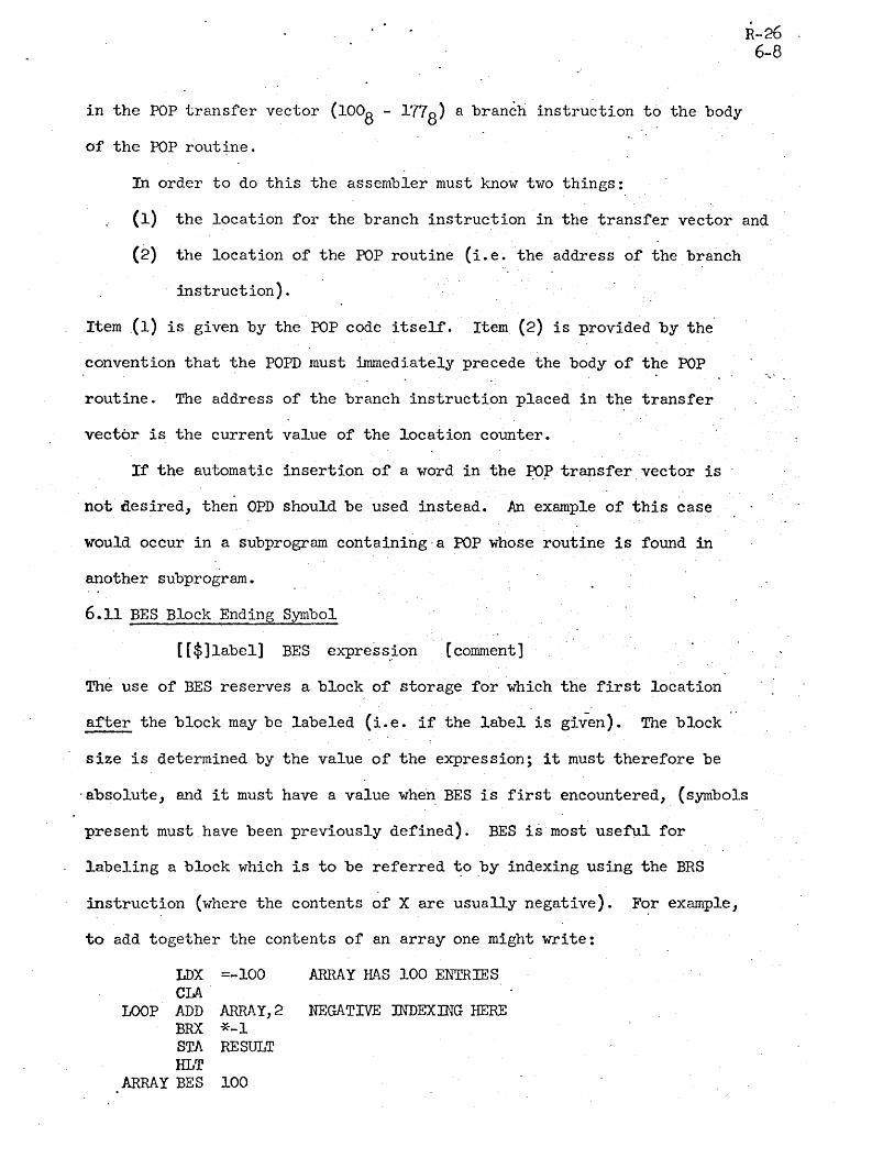
6.11 BES Block Ending Symbol
[[$]label] BES express.~on [comment]
The use of BES reserves a block of storage for which the first location
after the block may be labeled (i.e._ if the label is given). The block
size is determined by the value of the expression; it must therefore be
'ab~olute, and it must have a value when BES is first encountered, (symbols
present must have been previously defined). BES is most useful for
labeling a block which is to be referred ~oby indexing using the BRS
instruction (where the contents ~f X are usually negative). For example,
to add together the contents of an array one might write:
LDX =-100 ARRAY HAS 100 ENTRIES CIA -
LOOP ADD ARRAY,2 NEGATIVE TIffiEXlliG HERE BRX *-1 STA RESULT HLT
ARRAY BES 100

6.12 BSS Block Starting Symbol
[[$]label] BSS expression [comment]
The use of BSS reserves a block of storage for which the first word may
be labeled (if the label is given). The block size is determined by the
value of the expression; it must therefore be absolute, and it must" have
a value when BSS is first encountered. ·The difference between BSS and BES
o-~
is that in the case of BSS the first word of the ~lock is" labeled, whereas'"
for BES the first word after the block is lab~led by the associ'ated symbol ..
BSS is most useful for labeling a block which is referred to by positive .'
indexing (cf. 6.11 above).
6.13 ORG Program Origin
ORG expression (comments]'
The use of ORG forces an absolute assembly. The location counter is
initialized to the value of the expression. The expression must therefore
.be absolute, and it must have a value when ORG is first encountered.
Pn ORG must precede the first instruction or data item in an absolute
program, although it does not necessarily_have to be the first statement;
The output of the assembler will have a.bootstrap loader at the front
which is capable of loading the program after initiation by th~ 940
FILL switch.
6.14 END End of Assembly
END (expressi~n]
The END directive terminates the assembly. For 'relocatable assemblies,
no expression is used. For absolute assemblies the expression gives the
starting location for the program. When assembling in absolute mode,
the assembler produces a paper tape which can be read into the machine
with the FILL switch, i. eo, out of the time-sharing mode. If the
expression is not included with the END directive, the bootstrap loader

n-cu 6-10
on this paper tape will halt after the tape has read in. Otherwise, control
will automatically transfer to the location designated in the expression.
6.15 DEC Interpret Integers as Decimal
DEC [comments]
Integers terminated with B or D are always interpreted respectively as
being oct2l or decimal. On the other hand, integers no~ terminated with
these letters m~y be interpreted either as dectmal or octal depending on
the setting of a switch inside the assembler. The mode controlled by this
switch is set to decimal by the above directive.
When the assembler is started this mode is initialized to decimal •.
Thus, the DEC directive is not really necessary unless the mode has been
changed to octal and it is desired to return it to decimal. .
6.16 OCT Interpret Integers as Octal
OCT [cqmments]
As noted in 6.15 above, this directive sets a mode within the assembler
to interpret unterminated integers as octal. When the assembler -is
started this mode is initialized to decimal. Thus, the OCT directive
must be used before unterminated octal integers can be-written.
6.17 BAD Set Special Relocation Radix
RAD expression [comment]
As explained in 4.7 it is possible in a limited way to have multiple-
relocated symbols. This action is performed when the special ~elocation
operator (R) is used. The value of a symbol preceded by (R) is multiplied
by a constant called the radix of the special relocation. The loader is
informed of this situation so that it can multiply the base address by this
same constant before performing the relocation. Because the special

R-26 6-11
relocation vTaS developed specifically to facilitat"e the assembly of string
pointers (cf. 4.7), this constant is initialized to 3. If' it is desired
to change its value, however, the RAD directive must be used. The value
of the expression in the operan? field sets the.new value of the radix.
It must be absolute, and the expression.must have a value when it is
first encountered.
6.18 FRGT Forget Name of Symbol
[comment]
where s. are pre,viously defined symbqls 1
The use of FRGT prevents the symbol(s) named in its operand field from
being listed or delivered to DDT. FRGT is esp~cially useful in situations,
for example, where symbols have been used in macro expansions or conditional
assemblies. Frequently such symbols have meaning only at assembly time; . '
they have no connection whatever with the program being assembled. When
DDT is later ,used, however, memory locations sometimes are printed out
in terms of these meaningless symbols. It is desirable to be able to ,
keep these symbols from being delivered to DDT .
. 6.19' IDENT Program Identification
symbol IDENT [comment]
!DENT causes the symbol found in its label field to be delivered to DDT
as ? special identification record. DDT uses the IDENT name in conjunction
with its treatment of local symbols: in the event of a name conflict
betvreen local symbols in tyro different subprograms, DDT resolves the
ambiguity by allovring the user to concatenate the prec~ding mENT name
to the symbol in question.
!DENT statements are othervrise useful for editing purpos~s. They
are always listed on pass 2, usually on the teletype.

6.20 DELSYM Delete Output of SYmbol Table and Defined Op-codes
DELSYM [comment]
DELSYM inhibits the symbol table and opcodes defined in the course of.
assembly from being output for later use by DDT. Its main purpose is to
shorten the object code output from the assembler. This might be
especially desirable for an absolute assembly wqich produces a paper tape '-
which is to-be filled into the machine.
6.21 RELORG Assemble Relative with Abs.olute Origin
RELORG expression [comment]
On occasion it is desirable to assemble in the midst of otherwise normal
R-26 6-12
program a batch of code which, although loaded into core ~n some position,
is destined to run from another position in memory. (It will first
have to be moved there in a block.) This is particularly useful when
preparing program overlays.
RELORG, like ORG, takes an absolute eA1?ressio~ denoting some origin
in memory. It has the following effects:
(a) The current value of the location counter is saved, i.e. the ..
value of the expression and in its place .is put the absolute
origin. This fact is not revealed to DDT, however; during
loading the next instruction assembled will be placed in the
. next memory cell available as if nothing ha~ happened.
(b) . The mode of assembly is svTitched to absolute without changing
the object code format; it still looks like relocatable binary
program to DDT. All symbols defined in terms of the location
counter will be absolute. Rules for computing the relocation
value of expressions are those for absolute assemblies.
It is possible to restore normal relocatable assembly (cf. 6.22, RETREL).

Some examples of the use of RELORG follow:
(1)' A program begins "lith RELORG 300B and ends "lith END. The
assembler's output represents an absolute program whose origin is 0030°8
but which can be loaded anYVlhere us ing DDT in the usual fashion. (It'
is, of course, necessary to move the program to location 0030°8' before
executing it.)
R-26' 6-13
(2) A program starts and continues normally as a relocatable program.
Then there is a series of RELORGs and some RETRELs .. The effect is as
sho1;'lIl below:
} Normalrelocatable program •
RELORG . 100
J Absolute program or.igined to 100
RELORG .:200
} Absolute program origined to 200
RETREL
} Normal relocatable program
RELORG 300
J Absolute program origined t~ 300
END
6.22 RETREL Return to Relocatable Assembly
RETREL (comment]
This directive is used when it is desired to return to relocatable assembly
after having done a RELORG. It is not necessary to use RETREL unless'one
desires more relocatable program. The use of RETREL is shown in 6.21.'
The effects of RETREL are
(a) to restore the location counter to what it would have'been
had the RELORG(s) never been used, and
(b) to return the assembly to relocatable mode.
6.23 FREE7~ Preserve Symbols, Op-codes) and Macros
FREEZE [comment]
It is sometimes true "Then assemb'ling various sub-programs that they share
R-26 6-14
definitions of symbols, op-codes, and macros. It is possible to cause the
assembler to take note of the current contents of its symbol ~nd opcode
tables and the currently defined macros and include them in future
assemblies, eliminating the need for including copie.s of this information
in every subprogram's source language. This greatly facilitates the.
editing of this information.
When the FREEZE dir~ctive is used, the current table boundaries for
symbols and opcodes and the storage area for macros is noted and saved away
for later use. These tables may then continue to expand during the curr~nt
assembly. (A separate sub-program may be used'to make these definitions.
It will then end with FREEZE; END.) The next assembly may then be. started
with the table boundaries returned to what they were when FREEZE was last
executed. This is done by entering the ass.embler at its continlle entry
point, i.e. one types
. @. CONTJNUE ARPAS.
Note that when the assembler has been pre-loaded with symbols, opcodes
and macros, it cannot be released (i.e. one c·annot use ~nother s~b-system
like DDT, QED, etc.) without the loss of this information.

6.24 NOEXT Do Not Create External Symbols
Because of its subprogram capability, the assembler assumes auto-
R-26 6-15
matically that symbols which are not defined in a given program are external
and will be defined in another subprogram. It does not therefore list out
the use of. such symbols as errors.
If a program is in fact a.free-standing program, i.e. if it is
supposed to be complete, then clearly symbols which are not defined are
errors and shoulu be so noted in assembly. The NOEXT directive simply
prevents external symbols from being established; thus undefined symbols
are noted as errors. Tne directive must be used at the beginning of a "
program before instructions or data have been assembled. Its use affects·
the entire program. Its form is
NOEXT {comment]
6".2j LIST Turn SpeCified Listing Controls on
6.26 NOLIST Turn ?pecified Listin~.~ontrols Ofr
Most assemblers provide a means of listing. a program during assembly,
i.e. printing out such items as the location counter, binary code being
assembled, source program statement, etc. The association of these items '. .
on one page is frequently of great help to programmers. Two directives,
LIST and NOLIST, control this process. Their form is as follows:
LIST} NOLIST
[comment]
where the s. are from a set of special symbols having ~
"meaning only when used with these directives.
There are many listing options for this assembler. A list of special
mnemonic symbols used in conjunction with these two directives is given
below. The symbolf? have special meaning only when used with LIST and
NOLIST. They may be used at any other time for any particular purpose.
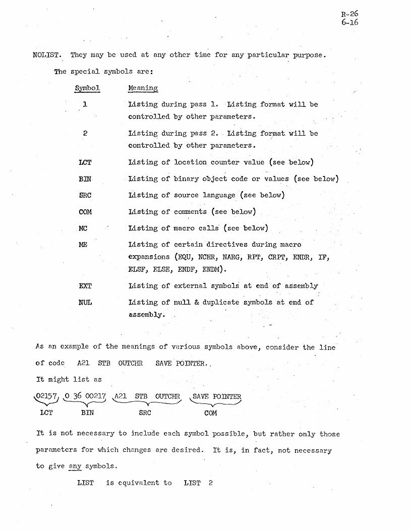
The special symbols are:
Symbol
1
2
LCT
Em
SRC
COM
MC
ME
EXT
NUL
Listing during pass I. Listing format will be
controlled by other parameters.
Listing during pass 2. Listing format will be
controlled by other parameters.
Listing of location counter value (see below)
Listing of binary object code or valu~s (see below)
Listing of source language (see below')
Listing of comments (see below)
Listing of macro calls" (see below)
Listing of certain directives during macro
expansions (EQU, NCHR, NARG, RPr, CRPI', ENDR, IF,
ELSF, ELSE, ENDF, ENDM).
Listing of external symbols at end of assembly
Listing of null & duplicate symbols at end of
assembly.
As an example of the meanings of various symbols above, consider the line
of code A2l STB OUTCHR SAVE POJNTER •.
It might list as
~ ~0S'21~ ~2l S~~ ~ LeT BIN SRC COM
It is not necessary to include each symbol"possible, but rather only those
parameters for which changes are desired. It is, in fact, not necessary
to give any symbols.
LIST is equivalent to LIST 2
R-26 6-16

R-26 6-17
When the assembler is started) it initializes itself in the follo,.,ing
way:
- LIST
NOLIST
The actual format of the assembly listing is controlled by the current
combination of parameter values. The parameters are independent items
except for the parameters Me and ME. In this case it is more reasonable
to think of their combination. Thus:
MC ME
o o
1 o
o 1
1 1
Effect
List outer level macro calls only
List all macro calls and code generated) but
suppress listing of certain directives (see ME
in table above).
List no macro calls) but rather all -co~e generated
except for certain directives.
List everything involved in macro expansions.
. Regardless of the'list control parameters which have been giv~n to
the assembler) it can be made to begin listing at- any time in either pass
. t,-'
simply by typing a single rubout (typing a 'second rubout in succession will
abort the assem~ly). Listing having been started -in this manner can be
stopped by typing the letter S.
6.27 PAGE Begin New Page on Assembly Listing
PAGE (comment]
This directive causes a page eject on the assembly listing medium
unless a page eject has just been given. It is used to improve the
appearance of the assembly listing.
6.28 REM Type Out Remarks in Pass 2
REM remark to be typed
This directive) when encountered in, pass 2) causes the contents of

its operand and comments fields to be typed out either O!1 the Teletype
or whatever file has been design2ted as the output message device. This
tYPeout occurs regardless of whRt listing modes are set. The directive
may be used for a variety of purposes. It may inform the user of the
progress of assembly. It may give him instructions on-what to do next
(this might be especially nice for complicated assemblies). It might ,-
announce the last date the source language was updated. Or; it might be
used within complex macros to shovl which argument substrings have been
created during expansion of a highly nested-macro (this for debugging
purposes).
R-26 6-18

, 7.0 Macros an~ Conditiona~ Assembl~
Assemblers with good macro and conditional assembly capability can have
surprising poy-rer. This assembler features such capability. In this section
the facilities for dealing with macros and conditional assembly will be
discussed. Many examples wtll be given.
7.1 Introduction to Macros
R-26 , 7-1
On the simplest level a'macro name may be thought of as an abbreviation
or shorthand notation for one or more ass~mbly language statements. In
this respect it is like an opcode. The opcode is the name of a bin8.!Y
machine command, and'the'macro name is the name of a sequence of assembly
language statements.
EXAMPLE 7-1 •
. The 940 has an instruction for skipping if the contents of a specified
location are negative, but none for testing the accumulator. SKA (skip
if' memory and accumulator do not compare ones) "Till serve when used ~ith
a cell "Those contents mask all but the sign bit. The meaning of SYJ\ used ,
in this way is "skip ~f A positive. tf Thus a, progrrumner will write
SKA BRU
=4B7 NEGCAS NEGATIVE CASE
Programs, hOvrever J are more than likely to have a logical need for
skiPPing if the accumulator is negative. In these situations the programmer
. must write SKA BRU BRU
=4B7 *+2 POSCAS POSITIVE CASE
Both of these situations are awhlNard in terms of assembly-language
progr amming.
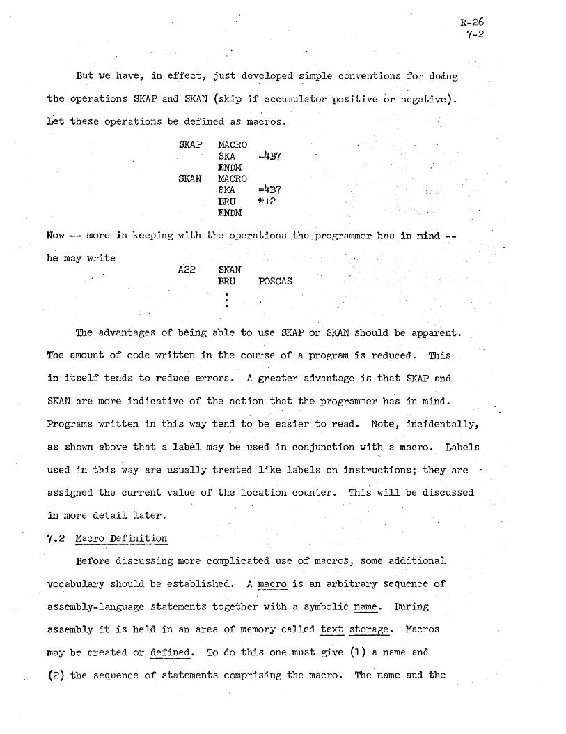
But we have, in effect, just developed simple conventions for doing
the operations SKAP and SKAN (skip if accumulator positive or negative).
Let these operations be defined as macros.
SKAP MACRO SKA =4B7 ENDM
SKAN MACRO . SICA =4B7 BRU *+2 ENDM
Now -- more in keeping with the operations the.programmer has in mind
he may write A22 SKAN
BRU POSCAS
R-26 7-2
The advantages of being able to use SKAP or SKAN should be apparent.
The amount or code written in the course of a program is reduced. This
in' itself" tends to reduce errors. A greater a.dvantage is that SKAP and
SKAN are more indicative of the action that the programmer has in mind.
Programs written in this way tend to be easier to read. Note, incidentally,
as sh01m above that a label may be· used in conjunction ~ith a macro. Labels
used in this way are usually treated like labels on' instructiqns; they are
assigned the current value of the location counter. This will be discussed
in more detail later.
7.2 Macro Definition
Before discussing more complicated use of macros, some additional
vocabulary should be established. A macro is an arbitrary sequence of
assembly-language statements together with a symbolic~. During
assembly it is held in an area of memory called text storage. Macros
may be created or defined. To do this one must give (1) a name and
(2) the sequence of statements comprising the macro. The name and the
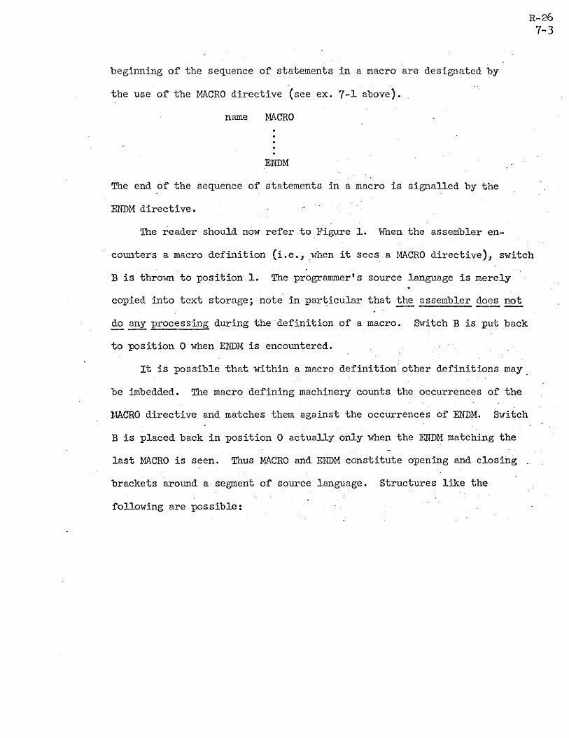
beginning of the sequence of statements in a macro are designated by
the use of the MACRO directive (see ex. 7-1"above).
name MACRO
ENDM
The end of the sequence of statements in a macro is signalled by the
ENDM directive.
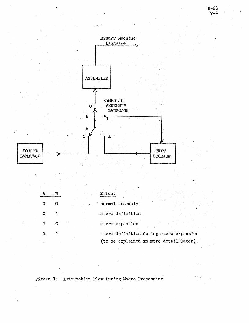
The reader should now refer to Figure 1. When the assembler en-
R-26 7-3
counters a macro definition (i.e., "when it sees a MACRO directive), s'YTitch
B is"thrown to position 1. The programmer's source language is merely
copied into text storage; note in par~icular that ~e assembler does not
~~ processing during the "definition of a macro. Switch B is put back
to position 0 when ENDM is encountered.
It is possible that within.a macro definition other definitions may
be imbedded. The macro defining machinery counts the occurrences of the
l~CRO directive and matches them against the occUrrences .of ENDM. SvTitch
B is "placed back in position 0 actually only when the ENDM matching the
last MACRO is seen. Thus lf~CRO and ENDM constitute opening and closing
brackets around a segment of source language. structures like the
following are possible:
SOURCE LANGUAGE
A
0
0
1
1
B
0
1
0
1
Figure 1:
Binary Machine Langua e·
t----..::::-~--;>_
ASSEMBLER
SYMBOLIC ASSEMBLY
LANGUAGE
1
l'
Effect
normal assembly
,macro definition
macro expansion
TEXT STORAGE
macro definition during macro expansion
(to be explained in more detail later).
Information Flow During Macro Processing
R-26 .7-4

name 1 MACRO
name 2 MACRO
name 3 MACRO
1 ENDM
name4 MACRO ] . '-
ENDM
ENDM ".
name5 MACRO ] ENDM
ENDM
The utility of this structure will not be discussed here. Use of this
feature of imbedded definitions should in fact be kept to a minimum since
the implementation of this assembler is such. that it uses large amounts
of text storage in this case. What is ~portant, however, is an under-" .
standing of when the various macros are.defined. In particular, when
namel is being defined, name2,3, etc. will ~ be defined; they are
merely copied unchanged into text storage. Name2 will not be defined
* Until namel is used.
7.3 Macro E~~ansion
The use" of a macro name "in the opcode field of a statement" is referred
to as a call. The assembler, upon recognizing a macro call, moves switch A
to position 1 (again see Figure 1). Input to the assembler from the
original source language ceases tempOrarily and c~mes instead from text
storage. During this period the macro is said to be und~rgoing expansion.
* It should be noted that macros -- 1L~e opcodes -- may be redefined.
It is clear that a macro must first be defined before it is called.
An expanding macro may include other macro calls; and these, in
turn, may call still others .. In fact,'macros may even call themselves
(when this makes sense). This is called recursion. Examples of the
recursive use of macros are given later. When within a macro expansion
R-26 7-6
a new macro expansion begins, ~nforraation about the progress of the current
expansion is put away. Successive macro calls cause similar information
to be saved. At the end of each expansion the information about each
previous expansion is restored in inverse fashion. When the final
expansion terminates, swit~h A is placed back in position o. Input then
resumes from the source language program.
7.4 Macro Arguments
Now let us carry exrunple 7-1 one step further. One might argue that
the action of skipping is. itself awkward. It might be preferable to write
macros BRAP and B~ (branch to specified location if contents of accumulator
are positive 'or negative). How is one to do this? The location to which
the branch should go is not known when the macro is defined; in fact,
different locations will be used from call to call. The.macro processor,
therefore, must enable the programmer to provide some of the information
for the macro expansion at call~. This is done by permitting d~my
arguments in macro definitions to be replaced by arguments (i.e., arbitrary
substrings) supplied at call time. Each dummy argument is referred to in
the macro definition by a subscripted symbol. This symbol or dunmlY ~
. is given in the operand field of the MACRO directive.

EXANPLE 7-2
Let us define the macro BRAP.
BRAP MACRO DUM SKAN BRU DUM(l) ENDM
When called by the statement BRAP POSCAS
the macro will expand to give the statements
SKA =4B7 BRU *+2 BRU roSCAS
R-26 7-7
Note that BRAP was defined in terms of another macro SKAN (a matter
of choice in this example). Also note that as defined, BRAP ~Tas intended·
to take only one argument. Other macros may use more than one argument.
EXAMPLE 7-3
The macro CBE (compare and branch if equal) takes two arguments.
The first argument is the location of a cell to be compared for equality"
with the accumulator; the second is a branch location in case of equality.
The definition is
~ CBE MACRO SKE BRU BRU ENDM
vllien called by the statement
D Del) *+2 n(2)
CBE =2lB,EQLOC
the statements generated will be
SKE =21B BRU *+2 BRU EQLOC

Note that arguments furnished at call time are separated by commas~ .
R-26 7-8
It is possible to include both commas and. spaces in arguments by enclosing
the arguments in parentheses; the macro processor strips off the outermost
parentheses of any substring used in a call. For example in the call of
the ma.cro MUMBLE
MUMBLE A, (B,C),(n E)
we have
~m: ~,c D(3) = D E
7.5 The Use of Dummy Arguments in Macro Definitions
Before giving further examples of the use of macros, the various
ways that dummy arguments may be used in macro definitions will be.
discussed. In general a dunnny may be referred to· by the symbolism
dummy(expression)
·The only restriction on the expression above is that it must not contain
other dummies or generated symbols (see 7.7). Furthermore, for obvious , . *
reasons"it must have a kno~~ value when the macro is called.
I-bre than one dummy may be referred to by the notation
dummy(expression,expression)
In the case of the call
MUMBLE A,B,C,D,E
then
n(3,5)= C,D,E.
But it is possible to have confusion in this situation. If we have the call
MUMBLE A,B,C, (D)E),F
*It should be noted that a macro call may d.eliver more arguments than are referred to in its definition, but the converse is not true. A dummy argument not supplied with an argument at call time is considered an error.

then
DUM(3,5)= C,D,E,F
But which are DUM(3), DUM(4), and DUM(5)? To resolve this ambiguity," the
assembler produces in place ofDUM(3,5) the string
(c), (D,E), (F)
The notation
dummy()
R-2b
7-9
produces all of the arguments supplied in a macro call. Each is surrounded
by parentheses as in the example above.
The symbolism
dummy (0)
is legal and meaningful. It refers to the label field of the macro call.
Normally a label used with a macro call is assigned the current value of
the location counter (as with any instruction). Explicit use of dummy(O),
i.e., literal zero in parentheses, causes the label field not to be
handled in the normal way. It serves merely to transmit another argument.
There are three possible cases.
(1) Macro contains no references to dmnmy(O). Label field is
treated normally.
(2) Macro contains at least one reference t~ dummy(O). Label field
merely transmits an argument vThich r"eplaces dummy(O) in the
expansion.
(3) Macro contains no references to dummy(O) explicitly but does
contain dummy(expressi?n) where, at call time, the value of the
expression is zero. In this case the label field is handled as
in case (1) and also used to transmit the argument referred to by
dummy(expression) as in case (2).

The symbolism
is used to represent the terminal character o~the.opcode field} i. e.} to
deterrnin·e whether the macro name terminated with a blank or a * (in case
o~ indirect address). It allows macros to be ca~ed .with or without
"indirect addressing" specified. Thus in a typical call we have the
follOwing relationships:
Ml7, "-v-
I CALL-X~
t dummy-eO) dtunmy(-l)
Note that dummy(-l) is always one character long.
Sometimes in a macro definition it is desirable to refer .only to a
R-26 1
7-10
portion of an argument} perhaps to a character or a few characters. ):n the
case of a single character this may be done by writing
dummy(expression$expression) . .
The first expression designates which argument; the second determines
which character of that argument. If a substring of an argument is
desired} one writes
dummy(eA~ression$expression}expression)
The second and third expressions determine the first and last characters·
·of. the substring. For example, if we have the call
then
MUMBLE A} BeDE, t FGHIJ'
DUM(2 $3) = D
DUM(3 $4} 7) = Hut

Beginning with the ith character the latter part of an argument can be
obtained by specifying an overlarge terminal bound. Thus
DUM(2$4,IOOO) =·HIJ'
7.6 Conc~tenatio~
R-2b 7-11
It is frequently useful to compose statement? out of mac:ro arguments
(or parts of them) and other information given' in the macro definition.'
This is'done by concatenating the various objects,together, i.e. simply
writing them next to each other. It is possible to confuse the assembler
when doing this, however. For example, let the dummy name in a definition
be C, and suppose we wish to cone atenate the strings AB and C (3) . If vIe
v~ite ABC(3), then do we mean AB concatenated with C(3), A concatenated
with BC(3) (whatever that is), ABC(3), or what?
To avoid ambiguity vle use the character"." (dot or perio?-) as a
concatenation delimiter. For, the example just above we would write
AB.C(3), and no ambiguity then exists. The assembler uses the dot to
. delineate objects it must deal with; in pro'ducing output the macro' expansion
machinery after having'recognizedthe various objects stmply skips over"
the dots. ~ dot character cannot therefore be- used literally in !:macro
definition.
-', EXAMPLE 7-4
Let us define a macro STORE. Suppose we have established the
.conv~ntion that certain temporary storage cells begin with the letters
A,B,.· or X, depending on from what 940 register information is to be stored.
there. The definition is
STORE MACRO D ST.n(l$I).D(-l) D(l) ENDM
If called by the statements
STORE B17
STORE7<- x44

the macro will expand as
STB B17 or STXoX- x44
The dot is not actually needed in every incidence of concatenation.
R-26 7-12
Some programmers may readily determine for themselves when it ~s actually
needed. As a matter of good practice, however, when in doubt, use it!
7.7 Generated Symbols
A macro should not, of course, have in its definition an instruction
having a label. Successive calls of the macro.would produce a multiply.
defined symbol. Sometim~s, however, it is convenient to put a label on
an instruction within a macro. There are at least t\fO ways of doing this.
The first involves transmitting the label as a macro argument when it is
called. This is' most reasonable in many cases; it is in fact often
desirable so that the programmer can control the label being defined.
and can refer to it elsewhere in' the program.
However, situations do arise in which the label is used purely for
reasons local to the macro and will 'not be referred to elsewhere. In
cases iike this it is desirable to' allow for the automatic creation of ~
labels so that the progrrumner is freed from worrying about this task.
This may be done by means of the generated symbol.
A generated symbol ~ may be declared when a macro is defined. To
do t.his requires tw"O things; (1) the name and (2) the maximum number of
generated symbols which will be encountered during an exp·ansion. These
.two items may follow the dummy symbol name given in the' MACRO directive.
The actual format used is
nrune MACRO dummyname,generatedname,expression
For example, \Ve might have
MUMBLE MACRO D,G,4
ENDM
In the definition of this macro there might be references to
G(l), G(2), G(3), and G(4), these being individual generated symbols.
With regard to generated symbols the macro expansion machinery
operates in the follo'\ving fashion. A generated symbol base value for each
macro is initialized to zero at the beginning of assembly. As each
genera.t~d symbol is encountered, the expression -constitut~ng its subscript
is evaluated. This value is added to the base value, and the sum ,is pro-
duced as a string of digits concatenated to the generated symbol name.
Enough digits are produced to make the resultant symbol six characters
long. Thus, the first time MUMBLE is called, for example, G(2) vlill be
transformed into GOOO02, G(4) into GOooo4, etc.
At the-end of a macro expansion, the generated synfuol base value is
incremented by the amount designated by the exp~ession following the
generated symbol name in the ~~CRO directive. (This was 4 in the
-definition of MUMBLE above.) Thus the second call of MUMBLE will produce
in place of G(2),-coooo6, the third call will produce GOOO10, etc. It-
should be clear that a generated symbol name should be kept as short as
possible. It cannot _ be longer than 5 characters.
7.8 Conversion of a Value to a Digit string
As an adjunct to the automatic generation of symbols or ~or any other
_purposes for which it may be suitable a capability is provided in the
assembler's macro expansion machinery for conversion of the value of an
expression at call time to a string of decimal digits. The construct'
($expression)
will be replaced by a string of digits equal in value to the expression.
R-26 7-13

For example, let X = 5. Then
AB. ($2*X-l)
will be transformed into
AB9
Further examples of the use of this facility appe~r below.
7.9 The NARG and NCHR Directives
Macros can be more useful if the number of arguments supplied, at
call time is not fixed. The precis-e meaning of a macro (and indeed, the
results of its expansion) may depend on the n~ber or the arr~ngem~nt of
its argurrlcnts. In order to permit this th~ macro undergoing expansion must
be able to determine'. at call time the ,number of ar~ents supplied. The
NARG directive makes this possible.
NARG functions baSically like-EQU, except that no expression is used
with it. Its basic form _is
symbol NARG [comment]
The function 9f the directive is to _equate the value of the symbol to the
number of arguments supplied to the macro currently undergoing expansion.
The s~nbol can then be used by its~lf or in expressions for any required
purpose. Examples of the use of NARG appear later.
It is also useful to be able to determine at call time the number of
-characters in an argument. NCHR functions by equating-the symbol in 'its
label field to the number of characters in its operand field. Its form is
symbol NCHR character string [comment]
R-26 7-14
The notion of "operand field'~ must b~ elaborated on here. The operand field
normally terminates on the first blank after the beginning of the field.
This rule ~ rescinded if !:.. macro argument containing blanks appear .. ~ in
the ~rand field. For example, in the statement
XIZ LDA VECTOR, 2 THIS IS A COMMENT t t

1\-co 7-15
the arrows delineate the operand field. Alternative~, if a statement like
TEXT X,D(l).E1ffiOR
is placed in a macro definition and the macro is called by
MUMBLE (NON-FATAL)
then the above statement will turn out to be
TEXT X,NON-FATAL ERROR t t
Notice how the operand field terminates in this case •.
In the same example notice that the message produced by the text
directive is of unspecified length at definition time. Clearly, X must
depend on the number of characters in D{l). Accordingly; MUMBLE might be'
defined as
EXAMPLE 7-5
MUMBLE MACRO X NCHR X EQU
TEXT ENDM
7.10 Conditional Assembly
D D(l) X +9 5 FOR 'ERROR I ,4 TO ROUND UP X/4,D(1) . ERROR
The reader should see by now that the macro. is a powerful tool.
~ts power, however, is considerably multiplied when combined with the
features explained in this and the following sections. These features -
basically the if and repeat capabilities -- a~e called conditional .
assembly capabilities bec~use they permit assembly-time calculations.
to determine the source language actually assembled. They are, however,
not strictly a part of the macro facilities and may be used quite apa~t .
from macros.
...
\ .
7.11 The RPr Directive
The RPT (repeat) directive is, like the MACRO directive, an opening
bracket for a segment of program. Its form is
{1}· [label] RPr expression (comment]
or, using s for symbol, e for expression, and c for comment
(2)
(3)
[label] RPr
[label] RPr
(s=el ,[e2,]e3) [c)
(s=el,[e2,]e3}(s=el[,e2)(s=el[,e2)··· [c)
Form (1) says to repeat the follo~ing sequence ~f statements down to the
matching ENDR (end repeat) as many times as given by the value· of the
expression. Forms (2) and (3) are really the same form; they are shorm " "
. separately to emphasize that only the first parenthesized group in the
operand "field must be present. Their meaning is ~s follows:
(1) Set the symbol s to the value of e1 •
(2) Issue the sequence of statements dovm to the matching ENDR.
(3) Increment s by the value of e2
or by one (if e2 is not present).
If the new value of s has not passed the limit, go back
to (2). When the limit is passed, quit.
In other words, for symbol=e1 step e2 until e3 ~
or for symbol=e1 until e3
do •.•
Tne first parenthesized group (1) determines the number of times the
repeat is executed a~d'(2) controls the initial value and increment of a
symbol. Subsequent groups (there may be up to ten of them) mereiy control
the initial value and increments of other symbols carried"along in the
recent operation.
R-26 7-16

EXAMPLE 7-6
It is desired to· create an area of storage which is cleared to zero.
R-26 7-17
The BSS directive cannot be used for this purpose since i~s function (that
of reserving storage) is basicB:lly to advance the assembler's location
counter.· The problem is readily solved by
ABC
which is equivalent to
ABC
RPr DATA ENDR
DATA DATA DATA DATA
DATA
100 o
0 0 0 0
0
i 100 statement13
! Note that the label is applied effectively only to the first statement.

EXAMPLE 7-7
It is desired to fill an area of storage ",ith data starting ,,,ith 0
and increasing by 5 for each cell. We may write
x EQU 0 RPI' 20 DATA X
. X EQU X-t5 ENDR
.Alternatively (and more simply) ·one can "Trite··
RPl' (X=0,5, 100) DATA X ENDR
Note that in the latter form the terminal value (i.e., e3
) does not have
to be positive or greater than the initial value of the symbo~ bei~g
incremented.
. RPT (X=lOO, -5 , 20 )
and (X~INIT, -5 , - 30 ) RPI' ..
are both permissible.
Also note that a repeat directive followed by other statements and
R-26 7-18
an associated El~DR (referred to as a repeat block) may be imbedded in other
repeat blocks. This is similar to the imbedding of macro ~efinitions in
other macro definitions, and repeat structures similar to that shown in
section 7.2 may be used.

EXAHPLE 7-8
It is desired to" have a pair of macros SAVE and RESTOR for purposes
'of saving and restoring a~tive registers at the begi"nning and end of
subroutines. These macros should take a variable number of arguments
so that "one can write, for ex?~ple, ""
SAVE A,SUBRS
" or perhaps
RESTOR A,B,X,SUBRS
These calls are intended to generate the code
STA SUBRSA
and
LDA SUBRSA LDB SUBRSB LDX SUBRSX
We first define a generalized macro MOVE which is called by the same
arguments delivered to SAVE and RESTOR plus the stri~gs 'ST' and 'LD'"
which determine whethe"r one wishes to store or lpad.
MOVE MACRO D X NARG
RPr (Y=2,X-l) D(l). Dey) n(x). n(Y)" ENDR ENDM
Then, in terms of MOVE, SAVE and RESTOR are readily defined as
SAVE "MACRO D MOVE ST,n() " ENDM
RESTOR MACRO D MOVE LD,D() ENDM
R-26 7-19

EXAMPLE 7-9
Many programs "make use of flags, memory cells which are used as
binary indicators. The SKN (skip if memory negative) makes it easy to
test these flags. Let us adopt the convention that a flag is set if it
contains the value -1 and reset if' it contains zero. We want to develop
the macros SET and RESET to manipUlate flags. It is further desirable
"to deliver at call time the name of an active register whic~ will be used
for the action, together with a"variable-length list of flag locations.
Calls of these macros will look like
SET A,FLGl,FLG2,FLG3
or
RESET X,FLG37,FLG12
As in example 7-8 we make use of an intermediate macro STORE which
takes the same arguments.
STORE MACRO n X NARG
RPr (Y=2,X) ST.n(l) n(Y) ENDR ENDM
Thus SET and RESET are defined as
SET MACRO n LD.D(l) =-1 STORE D() ENDM
RESET MACRO D CL.D(l)
D() STORE ENDM
R-26 . 7-20

1.12 CRPT, Conditional Repeat
Occasionally one wishes to·perform an indefinite number of repeats,
termination coming on an obscure condition determined in the course of the ... -.
repeat operation. The conditional repeat directive, eRPI', serves this
function. Its effect is like that of RPr (and its ~epeat block -- like.
RPr-- is closed off by a matching ENDR) except that instead of giving
a number of repeats its associated expression is_evaluated each time in
. a Boolean sense to determine whether the repeat should occur again. Its
. (
form is
[label] CRPr expres~ion[,(s=el[,e2]),(s=el[,e2)···]
[comment]
One ~ay yITi te, for example,
CRPr X>Y
or CRPl' STOP, (X=1,2) (Y=-3)
Note that the statement
CRPr 10
will cause an infinite· number· of repeats.
The termination of a CRPT operation is governed by whether the value
of the expression is one or greater. Zero·or negative quantities are
taken to mean don't repeat (Boolean 0 or false). Values of one or greater
mean do r~peat (Boolean 1 or true).
An example of the use of CRPT is shown in example 1-11.
7.13 IF Capability
It is frequently desirable to permit the assembler either to assemble
R-~
7-~
or merely skip blocks of st~tements 1epending on the value of an expression
at assembly time. This is primarily what is meant by the term conditional
assembly. Conditional assembly can be done (inelegantly) with CRPT.
Let the condition be given by an expression. (Once again a Boolean
value is ascribed to an expression in the manner
o if e<0
1 if e>O.)
Then one may write
EXAMPLE 7-10
'(»
c EQU condition CRPT C
arbitrary block of statements C EQU 0
ENDR
Note that the line before ENDR is required to prevent the eRPT from going
forever. By using the structure above, however, conditional assembiy may
be done; the arbitrary block of statements enclosed in the repeat body
may be assembled on condition.
7.14 IF, Assemble Lif E:x-pression True (i.e., > 0)
The same function shown in example 7-10 is performed much more
conveniently by the IF directive. Its form is
[label) IF expression [commel1;t]
ENDF
As with RPT and CRPT, the IF directive defines the beginning of a block
of statements (called the i~ body) terminated bY,a matching E1~F. The
if body may contain other if bodies.
R-26 7-22
When doing conditional assembly there are often alternative if bodies
to be assembled in case a certain if body does not assemble. This situation
is most easily dealt with by the use of the ELSF and ELSE directives.
These ,provide an end to the if body and also begin another body which is
to be assembled (again possibly on condition) in case the first body did

not. For example, consider the following structure:
IF el
} bodYl
ELSF e 2
}bOdY2 ELSF e
3 } bodY3
ELSE l, bodY4
ENrlF If ei>0, bodYl is assembled and bodies2,3,4 are skipped (regardless of
e2
and e3
.
If el~O and e2>0, bodY2 is assembled and bodies1,3,4 are skipped.
If el and e2~O and ej>0, bodY3 is assembled and bodiesl ,2,4 are skipped •.
Finally if el , e2 , and e3<S..0, bOdY4 is assembled.'
An example of the use of IF (and other features) follows.
R-26 7-23

EXAMPLE 7-10
This example serves to illustrate several of the preceding features
-R-26 7-24
and also the power of macros used recursively. The macro MOVE is intended
to take any number of pai~s of arguments. The first argument of each pair
is to be moved to the second. Each argument, however, may itself be a
pair of arguments, which may themselves be pairs, etc.
We first define MOVE. Basically it extracts pairs of argument
structures and transmits such a pair to another macro MOVEI.
MOVEX
MACRO NARG RP1' MOVE 1 ENDR ENDM
D
(Y=i,2,X)(Z=2,~) D(Y),D(Z)
We now define MOVEI. It calls itself recursively until it comes, up 0.:
with a single pair of arguments. Then it generates code.
MOVE 1 G(l) G(2)
G(2) U V
MACRO NARG EQU IF LDA STA ELSE RPT EQU EQU EQU MOVE 1 ENDR ENDF ENDM
D,G,2
-rjJ
~m=2 D(2)
G(1)/2 G(2)+1 G(l) G(2) D(V) ,D(V+U/2)
Thus when called by the line
MOVE A,B
the code generated will be LDA A STA B

J,,-LU
7-25·
In this case the main call results in the call-
MOVE 1 (A,B),(C,D),(E,F),(G,H)
MOVEI .calls itself by ".
MOVE 1
and again: MOVE 1 A,E
where the first code is gen~rated. Then we get
Recursion then pops. up to the call
MOVE 1
and so on.

EXAMPLE 7-11
The following example makes use of virtually every feature in the macro
and conditional as~embly machinery. It is presented as a demonstration of
the power inherent in the use of macros but not as a" practical tool (critics
.have justly termed it the world,' s slowest compiler) ~ The macro COMPILE when
called with an arithmetic expr~ssion for its, argument produces assembly
language which computes the value of the expression in a minimum number of
steps (subject to the left-to-right scan technique u'sed). COMPILE in turn
R-26. 7-26
calls a large number of other 'macros. Their functions are explained by comments
in the text below:
The COMPIIE macro itself merely initializes some variables and calls
EXPAND where the more difficult work is done. J is the total number of
charOacters in the expression. K is used to keep track of the recursion level
on which the "lork is being done (EXPAND calls itself recursively when it s(!:es
an opening bracket [ ). 'AVAIL is the. counter for available temporary storage.
NPrR and PPm are stack pointers for the operand and operator stacks respe,ctively .. ' 0"'"
COMPILE MACRO D;J NCHR D(l);K EGU O;P.VAIL EQU l;NPTR EQU -l;PPTR EQU-l EX P t\ t,J D D ( 1 ); E ~ J D ~1
EXPAND initializes I, the current character pointer. It places
the value zero on the operator stack (marking its beginning on the current
level) and fetches the first operand. It then sets a switch (G(l» and goes
into a cycle of fetchi~g operators (GETP) and operands (GETN). If the
precedence of new operators is less than or equal to that of the previous
operators, code is generated. Otherwise the information is stacked and the
scan continued.
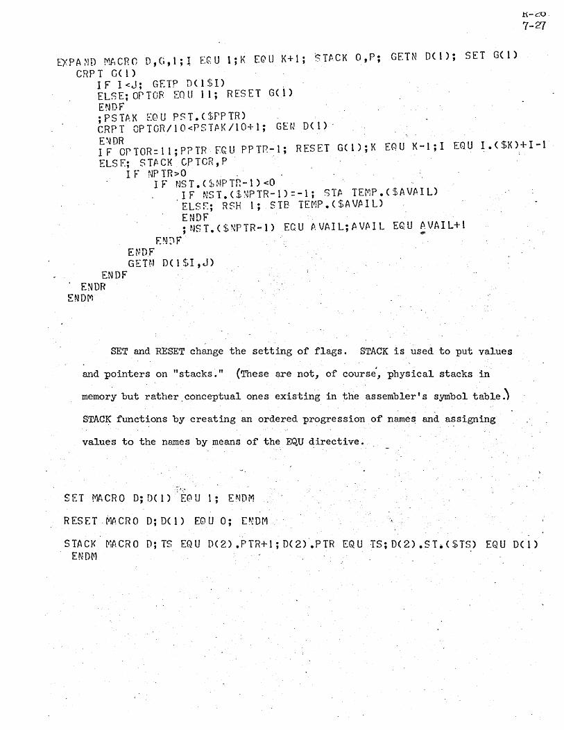
EX P A ~J D Mt, C ROD , (j , 1 ; l E QUI ; KEG' LJ K + 1; ·s T~. C K 0, P ; GET N 0 ( 1 ); SET G ( 1 ) CRP T G( 1 )
IF I<J; GETP D(lSI) ELSE;OPTOR EOU 11; RESET G(l) ENDF ;PSTf..K EQU PST.($PPTR) eRPT OPTOR/I0<PSTJ\K/IO+1; GEtJ D(l)·
.t{-c:o.
7-z/
i~D~PTOR=ll;P?TR FQU PPTr.~l; RESET G(l);K EQU X-I;! EQU !.($K)+I-i" ELS F.; S TI\ CK . CP TOR, P
I F NP TR>O . I F NS T • ( ~t, NP TP. - 1 ) <0
I F N ST. ( $ ~~ P T R - 1 ) = -1; S T Po T E f" P • ( $ A VA I L) 'ELSf.; RSH 1; SIE TEt1P.($AVPoIL)
ENDF ;NST.($NPTR-l) ECU fl,VAIL;AVAIL EQU ~VAIL+l
EN~F E~~DF GETN D(lSI,J)
ENDF ENDR
ENDM
SET and RESET change the setting of flags. STACK is used to put values
and pointers on "stacks." (These are not, of course',physl..cal stacks in
memor~ but rather.conceptual ones existing in the assembler's symbol table~
STAC~ functions by creating an ordered progression.of names and a~signing
values to the na~es by means of the EQU directive .
•. f"q
'" ".
SET MACRO D;D(I)·E0U 1; ENDM
R ES E T . MA C ROD; D( 1) EQ U 0; E ~ D r1
STACK tTiACRO D; IS EQU D(2) .PIR+l; D(2) .PTR EQU TS; D(2) .51.($TS,) EQU D( 1) END~1

GETN fetches the next operand. Its. complexity is. due to the fact that
it must recognize symbols (in this example using the assembler's symbol rules)
and numbers •. When this recognition is complete it puts in the· operand stack
R-cb 7-2&
a pair of pointers to the head and tail of the· operand (i. e., character" numbers
in the string and a flag bit '\>rhich denot'es whether the object is a symbol or
a number. Note that if an opening bracket is seen, GETN calls EXPAND recur~ively.
GETN' ~lACRO D; TO F.QU I; RESET ERROR; GETC D( 1 $1-TO+l) I F C H A H = ' [ , ; I • ( $ K) E QUI; EX PAN D 0 ( 1$ 2 ; J ) ELSE
I F LETTER; R.ES ET r~UM8ER ELS E;' S ET ~JUf'1P EP ENDF I F D1 G1 T; SET S~t}l TCH
eRP T S WI. Te}!; .GETC DC 1 $1 - TO+ 1 ) . I F D1 GI T
ENDR
ELSF LETTER; RESET SW1 TCH IF CH~R='B'; GETC D(I$I-TO+l)
IF LETTER; RESET NUMBER ELSF ,DIGIT; RESET r.JUr~8ER
.. E~]DF
ELS E; RES ET NUnB ER ENDF
ELS E; RES ET S \111 TCH E~~ D F ~
ELS F LETTER ELSE; SET EHROR ErJDF I F NUMBER ELSE; SET SWITCH
C R P T S tv'l T C H; GET C D ( 1 $ I - TO + 1 ) I F LET TEn
[NDH ENDF
ELSF D1 G1 T ELSE; RESET S~Jl TCH ENDF
IF ERROR; ERROR; STA.CK O,N ELS E; S TA CK TO* 1 B4+ 1- 2+4E- 3* NU~lEER, N . ENDF
; I EQ U I-I ENDF.
ENDt1

GETC's main function is to determine VThether a given character is a
letter, digit, or other type of character. GETP fetches' the next ·operator •.
It does some checking of the results and if valid sets 'OFTOR to a value
carrying both operator and precedence information'.
GETC ;V!ACRO D;CHpR EQU 9D(1) 9;1 EQU I+l;A'EQU CHAR>9Z9;E: EQU Cl-lAR<"A-I F A ( OR) [.; A EQ U CH f\ R> "9 9 ; B F Q 1I CH P R < '0 '
IF t-( CR)E'; RESET LETTER; RESET D1 GI T ELSE; SET DIGIT; R~SET LETTER ~NT)F
ELSF.; SET LETTER; RESET DIGIT ENDF
END~i
GETP ~1A CR 0 D; GETC D( 1 ) IF LETTER(OR)DIGIT; FRROR ELS E; A EG' U CHA R> 1186; E EQ U CHA R<20B6
I F P ( AND) D; or T OR EQ U OP S • ( $C H P R 11 E 6) . ELSF CHAR=']';OPTCR FrU 11 ELS E; OP TCR E(:' U -1 E~!DF
IF OPTOP=-t"; ERROR;OPTOR EGlI 40 ENDF
ENDF E~~Dn
GEN and GENA serve to reconstruct the operands from the string pointers
and call generators which actually produce code.
GEN NACRO D;R EGU -1;PP2 EOU·PST.($PPTR);PP3 EQU NST.($NPTR-l) ;PP4 EQU PP3/1P4;PP5 EQU PP3-?P4*lB4
IF PP5>4B3;PP5 EGU PP5~483; SET LIT1; RESET L1T2 ELS E; RES ET L1 T 1; RES ET LI T2 E~}DF
IF PP3>lP4; ~EN~ D(1),D(1$PP4,PPS) ELSF PP3>C; GENA 0(1) ,TEff;P.($PP3);AVPIL EQU PP3
.ELSF PP3=-1; GENt O(l),AREG ELS F PP3 = -2; GEt,lA. D( 1 ) ,t REG ENDF
; r~PTR EQU NPTR-2; STP.CK R,~,!;PPTR EQU PPTR-l;PST~K EeU PST.($PPTR) ENDM
n-c:.u
7-29

GENA MACRO Dj pp~' EQU NST. ($NPTR) ;PP6 EGU Pp5/1P.4 ; p P 7 EQ U P P 5 - P P 6 * 1 E 4 IF PP7>4B3;PP7 EQU PP7-483; SET LIT2 El\!!) F IF PP5>lP4; GEN It ($PP2) D(2),D(1$PP6,PP7) ELSF PP5>O; G~N.($PP2) D(2),TEMP.($PP5);AVAIL EQU PP5 ELS F P P 5 = - 1; G E r,~ • ( $ P P 2 ) 0 ( 2) , ARE G ELS F P P 5 = - 2; G EN. ( $ P P 2 ) 0 ( 2) ,B REG ENDF
~~DN
GEN20, 21, 30, 31 and 40 are the code producing macros. They make
referenc: to LIT1 and LTI2 (flags set by G~N and GENA) a-r:d call macros
TEST, "'LA, LB, and ST. 'The purpose of the latter macros is to 'Worryqabout
the meaning of the contents of the A and B regi~ters so as not to inject
superfluous code.
GEN20 ~W.,CRO D; TEST D( 1) ,D(2) ,X; LA D.(X) ,LI T.($X) . I F X = 1
ELSE
I F LI T2; ADD =. D ( 2 ) ELSE; ADD D(2) ENDF
IF LITI; ADD =.0(1) , EL 5 E; ,~ D D D ( 1 ) ENOF
ENDF EN~M
G E N2 1 Mt., eRa D ; T ES T D ( 2)" ,x I F x; LA D ( 2) ,L I T 2
I F LI T 1; C Nt.. ; P. D D =. D ( 1") ELS E; C N P. ; ADD D ( 1 ) . ENDF
ELS E; LA 0 ( 1 ) , LIT 1
. ENDF ENDM
I FLI T2; S us =. D ( 2 ) ELSEj SUB 'D(2) ENDF
R~~·26 7-30

GEN30 MACRO D; TEST D(I),0(2),>:; LA O(X),LIT~($X)
I FX = 1 IF LI T2; MUL = .0(2) ELSE; MUL D(2) EN~F
ELSE I F LI T 1; MUL =. D ( 1 ) ELSE; MUL D(l) ENOF"
ENDr. ; R EQ U -2
ENOM
G E N3 1 MA C ROD; T ES T D ( 2) ,X " I F X; S T D ( 2 $1); LP- D ( 1 ) ,L I T 1; D I V TEMP. ( $ A VA 1 L)
ELS E; "LB D ( 1 ) ,L I T 1 I F LI T2; D I V =. D ( 2) ELS E; Dl V "D( 2)
ENDF END~1.
ENDF
GEN40 ~~CRO D; NOP 0(1); NOP D(2) .ENDM
LA MACRO D IF'D(l)'='AREG· ELSF 'D(l)'='BREG'; LSH 23" ELSE
IF D(2); LOA =.D(I) ELSE; LDA 0(1)
ENDf ENDM
ENDr
LB MACRO D IF' D ( 1 )' = • BR EG' . ELSE
IF '0(1) '='AREG' ELSE
ENDr RSH 23 ENDr
ENOM
5T MACRO D
IF D(2); LDA =.D(1) ELSE; LDA 0(1) ENDF
IF' D ( 1 ) ., = 'BR EG '; RSH 1 ENOr
51.0(1$1) TEMP.($AVAIL)· ENOM
,t\-c:u
"7-31

TES T MA CR 0 .D; Y NAR G; DC Y) EQ U 0 RP T (Z =. 1 ,Y - I ) :
1Ft D ( Z $1 , 4) • = ' ARE G t ; DC Y ) EQ U Z ELSF 'D(Z$1,4)'='6REG';DCY) EQU·Z ENDr
ENDR IF Y>2
IF D(Y)=O;D(Y) EG!U EMDF •
ENOF ENDM
The following lines establish precedence information for the arithmetic
operators.
OPSIO EQU 30;OPSll EQU.20jOPS12 EQU -ljOPS13 EQU 21;CPS14 EQU-l OPS 1 5 EQ U 31
When called by the following lines, the macro generates code as sho,"m:
Call: COMPILE X+200*Y
·Result: . LDA =200 MUL Y ADD X
Call: COMPILE AB-[C+D]![E+F] ).
Result: LDA C ADD D STA TEMPI LDA ·E ADD F STA TEMP2 LDA TEMPI RSH 23 DIV TEMP2 CNA ADD AB
R-26' 7-32

Call: COMPILE
Result: LDA MUL LSH ADD STA LDA RSH DrV' STA LDA MOL LSH ADD MUL DrV' CNA ADD SUB RSH DIV eNA ADD SUB
A+200+34c2l-[DEF!34B-HI*[J~20*K]!LM33B - N]!OPQ-22
=200 34c21 23 . A TEMPl DEF 23 =34B TEMP2 =20 K 23 J HI LM33B
TEMP2 N 23 ON.
TEMPl =22
1 -;
R-26 7-33

7.15 ~ecial Symbols in Conditional Assembly
Although in the introduction it is stated that symbols 'consist " .
only of letters and digits, it is possible to include the co~on in
symbol~. DDT, however, does not regard the c~lon as pa~t of a symbol.
The meaning of this is that DDT will type out such symbols but they . . .
cannot· be typed in. In effect this makes them usel~ssJ arid it is for
this reason that the legality of colons in symbols has, just now been
mentioned.
Yet by judiciously. choosing when to use the colon in a ~ymbol
the feature can become worthwhile. In particul~r it can be used 'in
macros and other obscure places ~n t~e program to avoid possible
conflicts with other names. This might be particularly useful to
.d1-stinguish between symbols used in assembly-time calculations.and
those used at run-time.
R-26 7-34

8.0 Assembler Error Messages
upon discovering an error in the syntax of a.program being assembled, the
assembler will. list the statement in question and information about the
R-26 8-1
character of the error. The listing of errors will occur regardless of whether
regular listing is b~ing done.
8.1 Error Messages
Error messages and their interpretations are given below'. The first
group deals with difficulties found in a single statement.
Error Meaning
D Duplicate symbo1.
3'.,.
L Error in label field; most likely not a valid symbol.
M Missing field in statement.
0 Invalid or undefined opcode.
R Relocation error in expression. • "'!il-
S General syntax error.
U Undefined symbol.
If when calling a macro the user fails to deliver an argument required
during expansion, the assembler will replace the argument with the charactert
and issue an undefined symbol message. at that'point~
The second group of error messages deal with more complicated difficulties
Error Message
SYMBOL TABLE FULL. ERROR CHECK CONTINUES.
Meaning.
Too many synfuols and/or opcodes have been defined. Assembly will continue, but no new symbols or opcodes will be recognized. Break the program into. sub-progrruas or otherwise reduce the number of symbols present.

Error Message
LITERAL TABLE FULL. FURTHER LITERALS IGNORED.
MUST ASSEMBLE ABSPGM ON PAPER TAPE
mFUT STACK OVERFLOW
EOF -- END CARD ASSUMED
ILLEGAL COMMAND
mruT FILE NOT TEXT
BAD CHAR·
. l!OF IN HACRO DEFINITION
mror STACK UNDERFLOW'.
. mPUT BUFFER FULL.
...
Me an in&
'Similar to the case above. Reduce the n~ber of literals present.
R-26 8-2
The bootstrap.loader for self-filling, absolute assemblies is intended for paper tape only. Designating any other form on output file (except NOTHING and TELETYPE (another form of paper tape)) results in this message. It is possible to assemble an absolute program for loading by DDT. See 6.21 RELORG.
There ~re t~o many nested macro calls, repeats, and ifs in combination. The stack provided for storing the previous source of input is full., This is a disaster. The program must be reorganized.
No·ENDstatement~was found at the endot the program. The assembler (except for typing this message) takes the same action as if it found the END statement.
The assembler does not recognize a command typed ·in by a user upon start-up. It makes him start again.
The input file described to the assembler . is not a type 3 f_ile (i.e.·, text).
An unrecognizable character {or one otherwise out of place} is found in the text. The character is typed out in octal
_following the message, replaced by a blank ·in the text, and a~sembly continues.· .
The end of the program is reached, but the assembler is still defining a mac~o. Look for a missing ENDM.
The . oppos i te problem to the one above _ Not· terribly serious. Look for the presence of an extra ENDM, ENDR, or ENDF in the program.
An input statement must be less than 320 . characters long. This message occurs when tne rule is violated. It usuaily happens when macros run wild. Look carefully at the· program near vThere the error occurred.

Error Message
TOO l~CH MACRO RECURSION.
TOO MUCH RPT RECURSION.
TOO MANY ARGS IN MACRO.
. TOO MANY REPEAT ARGS.
STRING STORE EXCEEDED.
EOF IN TEXT.
8-3
Meaning
Too many nested macro.calls have occurred, resulting in filling available pushdo'\-m storage. Reorganize program.
Similar to above.
The macro is'being called with more arguments ·than there is space for. Reduce the number of arguments in the call.
. .
In beginning a repeat block, too many requests for automatic incrementing of symbols have been made. Reorganize the block ..
No space remains to store new macro definitions or to do repeats. Caution: old macro definitions are not thrown away. Do not redefine macros indiscriminately. Reorganize program. .
The end of the input file has occurred . in the middle of a statement.
8.2 Interpretation of the Error Listing
When an error is listed on any file other than TELETYPE, the single
letter error message (first group above) is listed in the line below at .
the point where the error was detected. Other information is given.
This is all depicted in the examples below.
In the following line there are errors in
001720 76 00000 UG~ 1
!?K+7) Current value" of location counter is 7 cells past the symbol EEK.
Label cannot terminate with /.
the label and operand fields.
LDA
~~. Relocation Expression error. cannot terminate
with -

20117 o 35 10761 STA ZOTn 0
hl-->MiSSing tag·
Lo/s+11 I JBI.E II DOLi{, Location Name of ~ Name of outermost counter. value.
innermost macro in which offense
occurred.
macro in which offense occurred.
Thus along with each error the location counter is printed o'ut relative
to the symbol most recently defined. In addition,. if the error occurs
during macro expansion the names of the innermost and outermost macros
are printed to give a clue on where to look for the error. If only
one level of macro expansion is involved, then only that name is listed.
In order to ~ave ttme when error listings are made .on the teletype,
the s ingle-letter error messages are typed out at the left marg:in.o
R-26 8-4

9.0 Assembler Operating Instructions
When the assembler is entered it asks first ,for the name of the binary
output file (characters typed by the user are underlined).
@ARPAS. BINARY:
The user types the name of the bin~ry file 'and confirms this n~~e either with
a comma or a period (a comma seems to the author to be preferable; 'both will
work). The, assembler then asks for ,the name of the source language file.
@ARPAS. BlliARi: 'Blli'L TIfPUT:,
R-26 9-1
The user types the input file name and confirms it either with a comma or period.
pifferent things happen in this case. If a period is typed assembly begins
immediately with the various assembler parameters preset to a set of standard
initial values. If a comma is typed the 'assembler expects to see one or more
of a number of commands which set its parameters to values other than standard
initial values. Each such command is terminated either by a comma (in some
cases a semi-colon) or a period. Assembly always begins when a period is
typed; a comma signifies yet another parameter change.
9.1 Assembler Parameters'
The assembler makes use of the parameters listed below. Parameters
(a) and (b) must be supplied. If after this a period is supplied, default
or standard values are given to the othe! parameters. These values are
noted in parentheses.
(a) binary output file (specified by user)
(b) source input file (specified by user)
(c) list (t~xt output) file (user teletype)
(d) error message file ,(user te~etype)
(e) listing parameters
(1) list on pass 1 (no, except for disastrous errors)
(2) 'list on pass 2 (no, except for errors)

.' (3) list symbol table (no)
(4) list nuil symbols (yes)
(5) list external symbols (ye~)
(6) list location counter value' (yes)
(7) list binary (octal) equivalent (yes)
(8) list source language (yes)'
(9) list comments (yes)
,!
(10) list program 'and outer level macro calls (no)
(11) list program and all macro calls (yes)
(12) list program and no macro calls (no)
(13) list program and details of macro expansions (no)
Parameter (c) may be changed from its default value by'the command
"TEXT OUTPUT: rt • Thus:
@ARPAS. BINARY: BIN.z... ll'TPUT: ~IN.L TEXT OUTPUT: L.
Normally, most error messages 'are output on the listing file. . Some'
particularly disastrous errors are always typed out on the teletype.
It is,possible, however, to specify the teletype as a binary output file
in which case it is used to punch a binary paper tape. It is necessary
lnsuch cases to designate some file --parameter(d)-- to receive those
error messages which would normally appear on the teletype. This is done
with the command "TTY MSG OUTPUT:".
@ARPAS. BINARY: !ELETr""PEL INPUT: ~INL TTY MSG OUTPUT: !:..'
Binary paper tapes punched on the teletype may be read with the 940 papee
p·,,26
9···2
tape reader. The assembler pauses fora few seconds after the final pel~iocl,
is typed to allow the user to turn on the teletype paper tape punch and
, turn off the printing mechanism.

The various parnmeters noted under (e) are the BRme parameters set
or reset by the LIST and NOLIST directives. They may be changed from
R-26 9-3
their default values by'the similar commands "LIST:" and "NOLIST:". Either
command expects to see one or more symbolic arguments (the same arguments
used with the corresponding directives). Because these arguments are
separated by commas, it is necessary to terminate the list either by a
period (starting assembly) or a semi-colon (if other parameters are yet
to be set).
@ARPAS.:.. BINARY: !!OTHINGL INFUT: ~INL !!IST: ME; !!OLIST: BIN,NULzEXT; TEXT OUTPUT: L.
The following table summarizes the above information.
Parameter
binary output file
source input, file
listing file
error message file
listing controls
Command to Set or Chan~e
BJNARY:<file name>
INRJT: <file name>
TEXT· OUTPUT: <file name>
TTY· MSG OUTPUT: <file name>
LIST: '\ <list of following NOLIST :) parameters> _
1.
1" ' 2
SYT NUL EXT-LeT BIN SRC COM MC
.. ME . .-:
-
Default value
none: must be by user.
none: must be by user.
teletype
teletype
no no no yes yes yes yes _ yes yes yes no -
specified
specified

9.2 Termination of the Assembly
The assembly process can be terminated by the user at any time
merely by typing t"ro or more rubouts in succession. The first rubout
causes the assembler to start listing (cf. 6.'26) 9
R-26 9~4
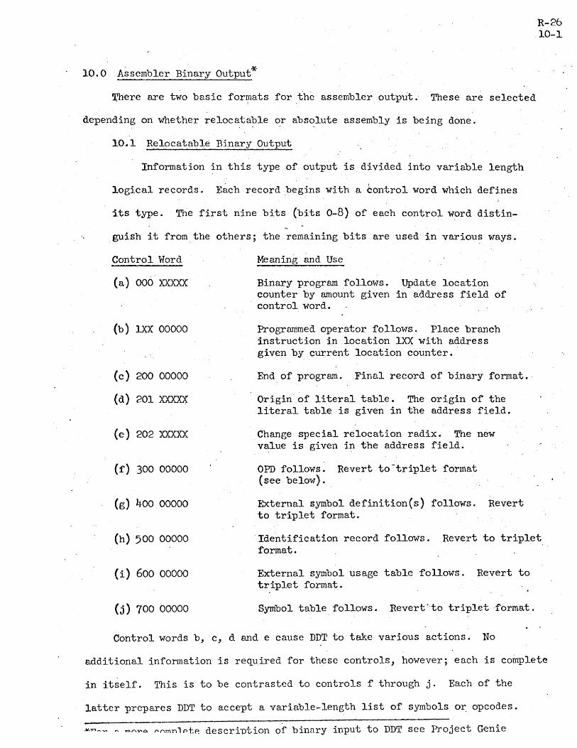
10.0 Assembler Binary Output*
Xllere are two basic formats for the assembler output. These are selected
depending on whether re10catable or absolute assembly is being done.
10.1 Relocatable Binary Output
Information in this type of output is divided into variable length
logical records. Each record begins with a control word which defines
its typee The first nine bits (bits 0-8) of each control word distin-
guish it from the others; the remaining bits are used in various ways.
Control Word
{a} 006 xxxxx:
{b} lXX 00000
(c) 200 00000
(d) 201 xxxxx:
(e) 202 xxxxx:
(f) 300 00000
(g) 400 00000
Me aning and Use
Binary program follm·rs. Update location counter by amount given in address field of control word.
Programmed operator follo,\"s. Place branch instruction in location !XX with address given by current location counter.
End of program. Final record of binary format.·
Origin of literal table. The origin of the literal table is given in the address field.
Change special relocation radix. The new value is given in the address field.
OPD follows. Revert to-triplet format (see below).
External symbol definition(s) follows. Revert to triplet format.
R-26 10-1.
(h) 500 00000 Identification record follows. Revert to triplet format.
(i) 600 00000
(j) 700 00000
External symbol usage table follows. Revert to triplet format.
Symbol table follows. Revert ~·to triplet ·format.
Control words b, c, d and e cause DDT to take various actions. No
a.dditional information is required for these controls, however; each is complete
in itself. This is to be contrasted to controls f through j. Each of the
latter prepares DDT to accept a variable-length list of symbols o~ opcodes.
~~~- n ~~~o ~~mnlpte descriution of binnry input to DDT see Project Genie

These lists are 'in so-called "triplet format" because the various symbols and
opcode s are handled as three-",ord ob.iects. Each list is terminated with a !:
word of all ones.
The contents of the address field of control word a are added to DDT's
location counter. This, control' signals that binar~ program' (i. e.' information
to be loaded) follows. The format of binary program consist~ of blocks of
eight words. Words in each block are either 10 ad able information or controls
of type a through e. Controls f through j also appear in binary, program;
.when one of them does, however, format immediately' reverts to triplet mode.
When the list of triples is 'terminated a new block of eight words is begun.
The first word in this block is always a control of some type.
There are seven different ways in which DDT treats information being
loaded.' It is necessary, therefore, that a three-bit byte be associated with
. each such word. Each eight-vlord block of binary progrrun format is preceded,
then, by a ",ord of eight three-b:Lt bytes. The association of bytes to words
is shovm below.
R-26 10-2

Byte Value
o
1
2
3
4
5
6
7
Meaning
Absolute address: load as is
. Evaluate address (mod 214) from external symbol usage table
Relocate address (mod 214)
Special relocation applies
Do not load: interpret word as a control
Derive entire word from external symbol usage table
Relocate entire word (mod 2~4)
Literal reference in address field
..
A p'ortion of binary output might, for example, have the following
appearance:
l{-cO
10-3
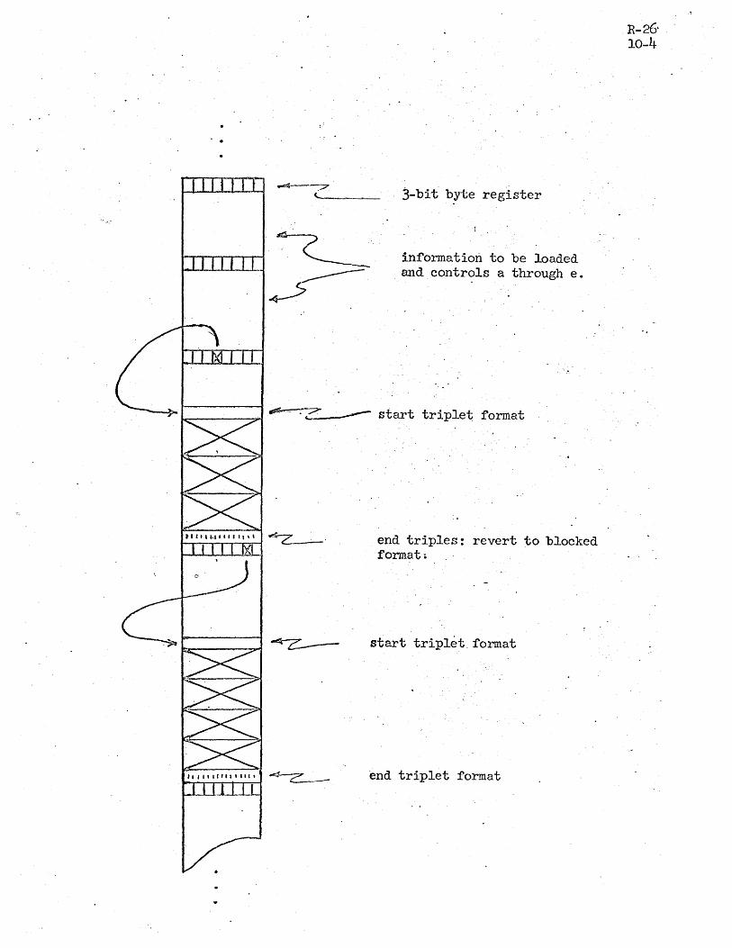
j-bit byte register
information to be loaded and controls a through e.
~ ______ ~ ~~ start triple~ format
end triples: revert to blocked format.
start triplet. format
end triplet format
R-26' 10-4

Finally, the format of a triple depends on whether it represents '\.
8. symbol or op code. For symbols the following hold$:·
o 5 6· 11 12 17 18 23 WDI 1
WD2 xxxxxx zeros
Symbol Value
C1
through C6 are the six significant characters of the symbol, left
justified with trailing blanks. Bits 12 through 17 of WD2 are flags
having the following meanings:
Bit Meaning -12 Relocatable Symbol
13 Duplicate Symbol.
14 ·External Symbol
15 Null Symbol
16 Generated Symbol . ~.'
17 Equated Symbol
Operation codes have the following format:
0 5 6 11 12 17 18 23
WDI I C1 I C2 I C
3 I C4 I WD2 I C
5 C6 Zeros
J:{-CQ
10-5

The fOr:il~t of WD3
bilities
(a)
(b)
are:
Class
WD3
Bit
9
19
23
Class
WD3
Bit
9
1
2
depends on the type of op code. The various possi-
instructions
o 1 8 9 19 23
EI op or pop Ixl zeros I X I zeros B code
Meaning
Set sign bit of instruction_
Operand required
-Type number (0 or 1)
Instructions
o 1 -8 9 10 23
El oP. or pop Ix I . remainder of code I code
Meanin~
Set sign bit of instruction
10.2 Absolute Assembly (Self-filling) Outpu~
R-26 10-6
For absolute programs, the assembler first punches' a bootstrap loader
and then program in variable-length blocks. A new block is begun whenever
it is necessary to jump the location counter ~head by more than one -or
when certain directives are encountered. The bootstr~p lo~der is q~ite a
primitive one. Ba~ically it executes repeatedly the first instruction. it
sees in each block of code while incrementing the X register. For program - .
blocks the first instruction in each block is an indexed store.
For other types of blocks (as, for example IDENT' records, OPD's,
or the entire- symbol table) the first word of each bloc~ is a NOP. END
with a >lank operand produces a new block beginning with HLT. In case

the operand is not blank, the last record begins with a transfer to
the location indicated. When this instruction is read by the loader
and executed, the loaded program is started. The loader uses location 1
for this purpose so that the program may be easily restarted by pressing
the machines' start button and throwing the Run-Step switch to Run.
R-26 10-7
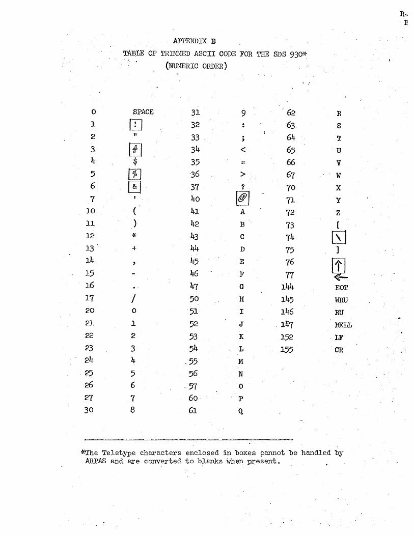
Q
1
2 3 4 5 6
7 10 11 12 13 14 15 16 17 20 21 22 23 24
.25 26
27 30
APPENDIX B
Tl$LE OF ~[tRIMMED ASCII CODE FOR THE SDS 93~
(NUMERIC ORDER)
SPACE 31 9 62
lTI 32 63 11 33 . 64 ,
[!J 34 < 65 $ 35 = 66
m "36 > 67 ~. 37 ? 70
40 [@1 71 ( 41 A 72 ) 42 B 73 ~4 ·43 C 74 + 44 D 75 , 45 E 76
46 F 77 47 G 144
/ 50 H 145 0 51· I 146 1 52 J - 1~7 2 53 K 152 3 54 L 155 4 .55 M
5 56 N
6 ·57 0
7 60- p
8 61 Q
R
S
T
·U
V
w X
y
Z
[
[SJ ]
~ EOT
WRU RU
BELL
-LF
CR
*The Teletype characters enclosed in boxes ~annot be handled by ARPAS and are converted to blanks when present. -
.