
2300-555 System Verification Software (SVS) Kits 3663-1 and 3668 ...
8
Quick Start Guide 2300-555 System Verification Software (SVS) Site Master S820E Cable and Antenna Analyzer 3663-1 Verification Kit, N Connector 3668-1 Verification Kit, K Connector This quick start guide provides a brief overview of the software installation and the use of the 2300-555 System Verification Software and 366x-1 Verification Kit with the Site Master S820E Cable and Antenna Analyzer. Anritsu Company 490 Jarvis Drive Morgan Hill, CA 95037-2809 USA Part Number:10580-00373 Revision: A Published: January 2014 Copyright 2014 Anritsu Company
Transcript of 2300-555 System Verification Software (SVS) Kits 3663-1 and 3668 ...
Quick Start Guide
2300-555 System Verification Software (SVS)Site Master S820E Cable and Antenna Analyzer 3663-1 Verification Kit, N Connector 3668-1 Verification Kit, K Connector
This quick start guide provides a brief overview of the software installation and the use of the 2300-555 System Verification Software and 366x-1 Verification Kit with the Site Master S820E Cable and Antenna Analyzer.
Anritsu Company490 Jarvis DriveMorgan Hill, CA 95037-2809USA
Part Number:10580-00373Revision: A
Published: January 2014Copyright 2014 Anritsu Company
1-1 PC Controller Requirements
2 PN: 10580-00373 Rev. A 2300-555 SVS for S820E QSG
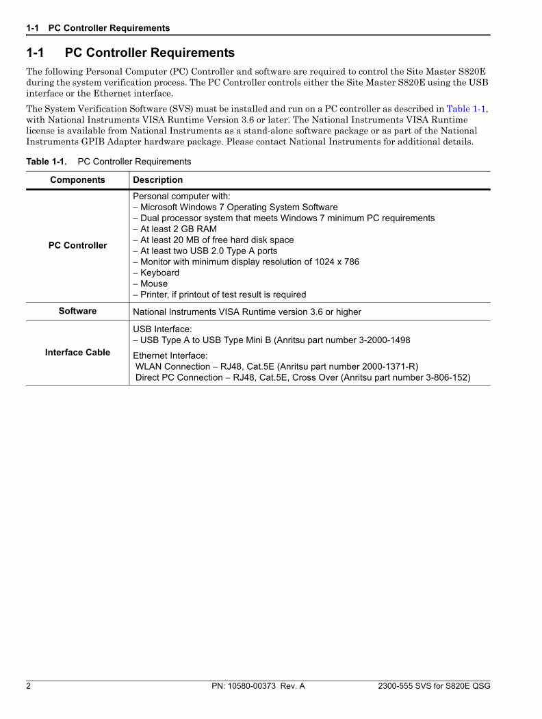
1-1 PC Controller RequirementsThe following Personal Computer (PC) Controller and software are required to control the Site Master S820E during the system verification process. The PC Controller controls either the Site Master S820E using the USB interface or the Ethernet interface.
The System Verification Software (SVS) must be installed and run on a PC controller as described in Table 1-1, with National Instruments VISA Runtime Version 3.6 or later. The National Instruments VISA Runtime license is available from National Instruments as a stand-alone software package or as part of the National Instruments GPIB Adapter hardware package. Please contact National Instruments for additional details.
Table 1-1. PC Controller Requirements
Components Description
PC Controller
Personal computer with:− Microsoft Windows 7 Operating System Software− Dual processor system that meets Windows 7 minimum PC requirements− At least 2 GB RAM− At least 20 MB of free hard disk space− At least two USB 2.0 Type A ports− Monitor with minimum display resolution of 1024 x 786− Keyboard− Mouse− Printer, if printout of test result is required
Software National Instruments VISA Runtime version 3.6 or higher
Interface Cable
USB Interface:− USB Type A to USB Type Mini B (Anritsu part number 3-2000-1498
Ethernet Interface: WLAN Connection − RJ48, Cat.5E (Anritsu part number 2000-1371-R) Direct PC Connection − RJ48, Cat.5E, Cross Over (Anritsu part number 3-806-152)
1-2 Required Test Equipment
2300-555 SVS for S820E QSG PN: 10580-00373 Rev. A 3
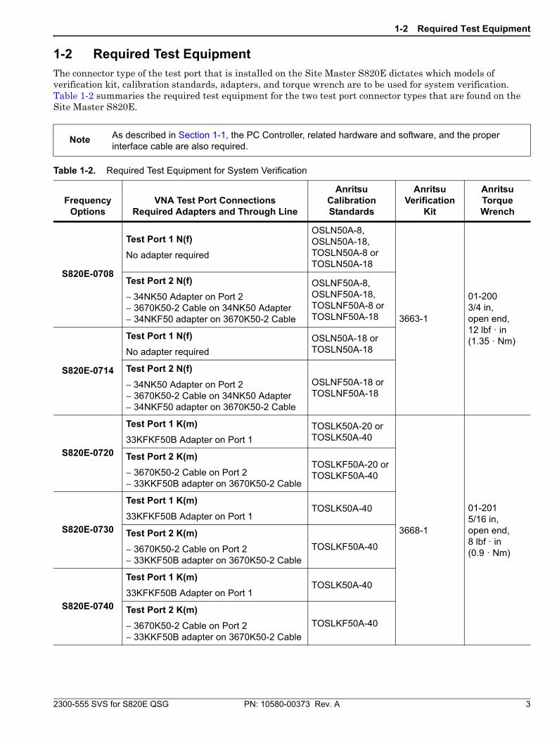
1-2 Required Test EquipmentThe connector type of the test port that is installed on the Site Master S820E dictates which models of verification kit, calibration standards, adapters, and torque wrench are to be used for system verification. Table 1-2 summaries the required test equipment for the two test port connector types that are found on the Site Master S820E.
Note As described in Section 1-1, the PC Controller, related hardware and software, and the proper interface cable are also required.
Table 1-2. Required Test Equipment for System Verification
Frequency Options
VNA Test Port ConnectionsRequired Adapters and Through Line
Anritsu Calibration Standards
Anritsu Verification
Kit
Anritsu Torque Wrench
S820E-0708
Test Port 1 N(f)
No adapter required
OSLN50A-8, OSLN50A-18, TOSLN50A-8 or TOSLN50A-18
3663-1
01-2003/4 in, open end, 12 lbf · in (1.35 · Nm)
Test Port 2 N(f)
− 34NK50 Adapter on Port 2 − 3670K50-2 Cable on 34NK50 Adapter− 34NKF50 adapter on 3670K50-2 Cable
OSLNF50A-8, OSLNF50A-18, TOSLNF50A-8 or TOSLNF50A-18
S820E-0714
Test Port 1 N(f)
No adapter required
OSLN50A-18 or TOSLN50A-18
Test Port 2 N(f)
− 34NK50 Adapter on Port 2 − 3670K50-2 Cable on 34NK50 Adapter− 34NKF50 adapter on 3670K50-2 Cable
OSLNF50A-18 or TOSLNF50A-18
S820E-0720
Test Port 1 K(m)
33KFKF50B Adapter on Port 1
TOSLK50A-20 or TOSLK50A-40
3668-1
01-2015/16 in, open end, 8 lbf · in (0.9 · Nm)
Test Port 2 K(m)
− 3670K50-2 Cable on Port 2− 33KKF50B adapter on 3670K50-2 Cable
TOSLKF50A-20 or TOSLKF50A-40
S820E-0730
Test Port 1 K(m)
33KFKF50B Adapter on Port 1TOSLK50A-40
Test Port 2 K(m)
− 3670K50-2 Cable on Port 2− 33KKF50B adapter on 3670K50-2 Cable
TOSLKF50A-40
S820E-0740
Test Port 1 K(m)
33KFKF50B Adapter on Port 1TOSLK50A-40
Test Port 2 K(m)
− 3670K50-2 Cable on Port 2− 33KKF50B adapter on 3670K50-2 Cable
TOSLKF50A-40
1-3 Verification Kit Components
4 PN: 10580-00373 Rev. A 2300-555 SVS for S820E QSG
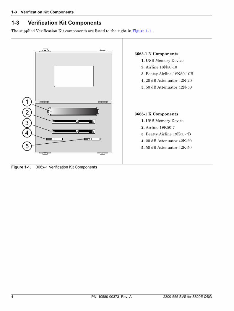
1-3 Verification Kit ComponentsThe supplied Verification Kit components are listed to the right in Figure 1-1.
3663-1 N Components
1. USB Memory Device
2. Airline 18N50-10
3. Beatty Airline 18N50-10B
4. 20 dB Attenuator 42N-20
5. 50 dB Attenuator 42N-50
3668-1 K Components
1. USB Memory Device
2. Airline 19K50-7
3. Beatty Airline 19K50-7B
4. 20 dB Attenuator 42K-20
5. 50 dB Attenuator 42K-50
Figure 1-1. 366x-1 Verification Kit Components
1
3
2
5
4
1-4 Installing the System Verification Software Application
2300-555 SVS for S820E QSG PN: 10580-00373 Rev. A 5
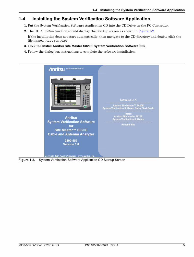
1-4 Installing the System Verification Software Application1. Put the System Verification Software Application CD into the CD Drive on the PC Controller.
2. The CD AutoRun function should display the Startup screen as shown in Figure 1-2.
If the installation does not start automatically, then navigate to the CD directory and double-click the file named Autorun.exe.
3. Click the Install Anritsu Site Master S820E System Verification Software link.
4. Follow the dialog box instructions to complete the software installation.
Figure 1-2. System Verification Software Application CD Startup Screen
1-5 PC Controller USB Connection to Site Master S820E
6 PN: 10580-00373 Rev. A 2300-555 SVS for S820E QSG
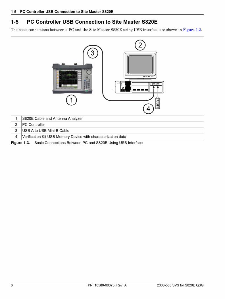
1-5 PC Controller USB Connection to Site Master S820EThe basic connections between a PC and the Site Master S820E using USB interface are shown in Figure 1-3.
1 S820E Cable and Antenna Analyzer
2 PC Controller
3 USB A to USB Mini-B Cable
4 Verification Kit USB Memory Device with characterization data
Figure 1-3. Basic Connections Between PC and S820E Using USB Interface
1
32
4 US
B
1-6 User Interface Operation
2300-555 SVS for S820E QSG PN: 10580-00373 Rev. A 7
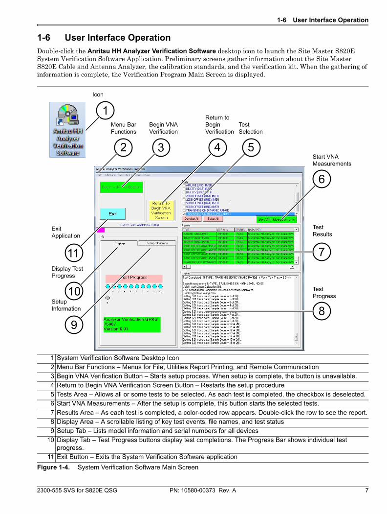
1-6 User Interface OperationDouble-click the Anritsu HH Analyzer Verification Software desktop icon to launch the Site Master S820E System Verification Software Application. Preliminary screens gather information about the Site Master S820E Cable and Antenna Analyzer, the calibration standards, and the verification kit. When the gathering of information is complete, the Verification Program Main Screen is displayed.
1 System Verification Software Desktop Icon
2 Menu Bar Functions – Menus for File, Utilities Report Printing, and Remote Communication
3 Begin VNA Verification Button – Starts setup process. When setup is complete, the button is unavailable.
4 Return to Begin VNA Verification Screen Button – Restarts the setup procedure
5 Tests Area – Allows all or some tests to be selected. As each test is completed, the checkbox is deselected.
6 Start VNA Measurements – After the setup is complete, this button starts the selected tests.
7 Results Area – As each test is completed, a color-coded row appears. Double-click the row to see the report.
8 Display Area – A scrollable listing of key test events, file names, and test status
9 Setup Tab – Lists model information and serial numbers for all devices
10 Display Tab – Test Progress buttons display test completions. The Progress Bar shows individual test progress.
11 Exit Button – Exits the System Verification Software application
Figure 1-4. System Verification Software Main Screen
Menu BarFunctions
Begin VNAVerification
Return toBeginVerification
TestSelection
Start VNAMeasurements
TestResults
TestProgress
SetupInformation
Display TestProgress
ExitApplication
Icon
8
10
9
711
1
32
6
54
1-7 Site Master S820E System Verification Procedure and Reports
Procedure
1. Connect the USB A to USB Mini-B cable between an open USB port of the PC controller and the USB Mini-B port on the Site Master S820E.
2. On the PC controller, launch the System Verification Software and click the Begin VNA Verification button.
3. When the Communication Interface dialog window appears, click the Find button under the USB ID Numbers, and then click the Check VNA Connection button.
4. After VNA connection is verified, click the Next> button to continue.
5. Insert the verification kit USB memory device into an open USB port on the PC controller.
6. Click the Auto-Find USB Drive Verification Kit Data button and then the Next> button.
7. Select the model of the calibration standards using the drop-down menu if using a calibration standard other than the model number that is displayed.
8. Enter the serial numbers of the Calibration Standards and then click the Next> button.
9. Click Next> (Begin Measurements), and the Main Test screen is displayed. See Figure 1-4.
10. Click the Start VNA Measurements button to begin.
11. Follow the instructions that appear on screen.
12. When all tests are complete, click the Exit button to quit.
Caution
Keep the airline or beatty standard center conductor concentric while connecting the through cable to the female port of the airline or beatty standard. Otherwise, severe damage to the center connector may result.
Use an appropriate torque wrench to tighten each connection to prevent over-straining of connectors and to ensure good repeatable measurement results.
Note
Any combination of tests can be selected. If all are selected, then the sequence is: VNA Calibration first, and then verification tests of Airline (DAT), Airline (UNC), Beatty Airline (DAT), Beatty Airline (UNC), 20 dB Offset (Pad) (DAT), 20 dB Offset (Pad) (UNC), 50 dB Offset (Pad) (DAT), 50 dB Offset (pad) (UNC), Transmission Dynamic Range, and Transmission High Level Noise.
Each verification standard test generates DAT CSV and UNC TXT reports. The DAT CSV reports are the current measured data for the user devices. The UNC TXT reports include the calculated uncertainty based on the measured data and the verification kit certification data. The reports can be viewed and printed within the software application by selecting the Utility Tools.
The Transmission Dynamic Range test and Transmission High Level Noise test generate TXT reports only.
Other applications, such as spreadsheets or word processors, can easily import the report data. The report files are located in the following folder:C:\Anritsu HH Analyzer Verification\VNA_Reports\Model_Serial Number
Anritsu prints on recycled paper with vegetable soybean oil ink.
Anritsu Company490 Jarvis Drive
Morgan Hill, CA 95037-2809USA
http://www.anritsu.com


![[3663] – 101](https://static.fdocuments.net/doc/165x107/61954ec3bcfa1b7b5b7cda09/3663-101.jpg)