230, 460, and 600 Volt Ratings 460, and 600 Volt Ratings efesotomasyon.com -Toshiba...
156
June, 1998 Part #47341-002 230, 460, and 600 Volt Ratings efesotomasyon.com -Toshiba inverter,drive,servo,plc
Transcript of 230, 460, and 600 Volt Ratings 460, and 600 Volt Ratings efesotomasyon.com -Toshiba...

June, 1998Part #47341-002
230, 460, and 600 Volt Ratings
efesotomasyon.com -Toshiba inverter,drive,servo,plc
efes
Typewriter
Toshiba E3 inverter user manual
efes
Typewriter

TOSHIBA
i
IMPORTANT NOTICE
The instructions contained in this manual are not intended to cover all details orvariations in equipment types, nor to provide for all possible issues concerningthe installation, operation, or maintenance of this equipment. Should additionalinformation be desired or should particular problems arise which are not coveredsufficiently for the purchaser's purposes, the matter should be referred to the localToshiba sales office.
The contents of this instruction manual shall not become a part of or modify anyprior or existing agreement, commitment, or relationship. The sales contractcontains the entire obligation of Toshiba International Corporation's AdjustableSpeed Drive Division. The warranty contained in the contract between the partiesis the sole warranty of Toshiba International Corporation's Adjustable Speed DriveDivision and any statements contained herein do not create new warranties ormodify the existing warranty.
Toshiba International Corporation reserves the right, without prior notice, to updateinformation, make product changes, or to discontinue any product or serviceidentified in this publication.
Any electrical or mechanical modification to this equipment,without prior written consent of Toshiba InternationalCorporation will void all warranties and may result in a safetyhazard in addition to voiding the UL listing.
AC ADJUSTABLE SPEED DRIVE
Please complete the Extended Warranty Card supplied with this inverter and returnit by prepaid mail to Toshiba. This activates the extended warranty. If additionalinformation or technical assistance is required, call Toshiba's marketing departmenttoll free at (800) 231-1412 or write to: Toshiba International Corporation, 13131 W.Little York Road, Houston, TX 77041-9990.
For your records, complete the following information about the drive with which thismanual was shipped.
E3 Model Number:
E3 Serial Number:
Date of Installation:
Inspected By:
Name of Application:
efesotomasyon.com -Toshiba inverter,drive,servo,plc

TOSHIBA
ii
INTRODUCTION
Thank you for purchasing the E3 adjustable speed drive. This adjustable frequency solid-state AC drivefeatures "True Torque Control" - Toshiba's 'vector algorithm' that enables motors to develop high startingtorque and compensates for motor slip. The E3 features a four character 7-segment type LED displaywith eight other discrete LEDs, RS232 port, dynamic braking transistor and ground fault, overload, andovercurrent protection. These features, combined with built-in special control features such as PID,drooping, trim, and dancer control, make this drive suitable for a wide variety of applications that requireunparalleled motor control and reliability.
It is the intent of this operation manual to provide a guide for safely installing, operating, and maintainingthe drive. This operation manual contains a section of general safety instructions and is markedthroughout with warning symbols. Read this operation manual thoroughly before installing and operat-ing this electrical equipment.
All safety warnings must be followed to ensure personal safety.
Follow all precautions to attain proper equipment performance and longevity.
We hope that you find this operation manual informative and easy to use. For assistance with your drive,for information on our free drive application school, or for information on Toshiba's complete line ofmotors, adjustable speed drives, switchgear, instrumentation, uninterruptible power supplies,PLCs, and motor control products, please call toll free (800) 231-1412 or write to our plant at: ToshibaInternational Corporation, 13131 W. Little York Road, Houston, TX 77041-9990.
Again, thank you for your purchase of this product.
COPYRIGHT © [APRIL, 1998] TOSHIBA INTERNATIONAL CORPORATION
efesotomasyon.com -Toshiba inverter,drive,servo,plc

TOSHIBA
iii
GENERAL SAFETY INSTRUCTIONS
Warnings in this manual appear in either of two ways:
1) Danger warnings - The danger warning symbol is an exclamation mark enclosed in atriangle which precedes the 3/16" high letters spelling the word "DANGER". TheDanger warning symbol is used to indicate situations, locations, and conditions thatcan cause serious injury or death:
2) Caution warnings - The caution warning symbol is an exclamation mark enclosed in atriangle which precedes the 3/16" high letters spelling the word "CAUTION". TheCaution warning symbol is used to indicate situations and conditions that can causeoperator injury and/or equipment damage:
Other warning symbols may appear along with the Danger and Caution symbol and are used to specifyspecial hazards. These warnings describe particular areas where special care and/or procedures arerequired in order to prevent serious injury and possible death:
1) Electrical warnings - The electrical warning symbol is a lighting bolt mark enclosed ina triangle. The Electrical warning symbol is used to indicate high voltage locations andconditions that may cause serious injury or death if the proper precautions are not
observed:
DANGER
CAUTION
2) Explosion warnings - The explosion warning symbol is an explosion mark enclosed ina triangle. The Explosion warning symbol is used to indicate locations and conditionswhere molten, exploding parts may cause serious injury or death if the properprecautions are not observed:
For the purpose of this manual and product labels, a Qualified Person is one who is familiar with theinstallation, construction, operation and maintenance of the equipment and the hazards involved (see1996 NEC (National Electric Code) Article 100 - Definitions).This person must:
1) Carefully read the entire operation manual (see 1996 NEC Article 110-3 "Installation andUse").
2) Be trained and authorized to safely energize, de-energize, clear faults, ground, lockoutand tag circuits and equipment in accordance with established safety practices.
3) Be trained in the proper care and use of protective equipment such as safety shoes,rubber gloves, hard hats, safety glasses, face shields, flash clothing, etc. inaccordance with established safety practices.
4) Be trained in rendering first aid.
efesotomasyon.com -Toshiba inverter,drive,servo,plc

TOSHIBA
iv
CONTENTS
PAGE
Disclaimer ............................................................................................. i
Introduction ............................................................................................ ii
General Safety Instructions .................................................................... iii
Contents ......................................................................................... iv-vii
Inspection/Storage/DisposalInspection of the New Unit ..........................................................................1-1Storage ..............................................................................................1-1Disposal ..............................................................................................1-1
Inspection and PrecautionsInstallation Safety Precautions ...................................................................2-1Operating Safety Precautions .....................................................................2-2Confirmation of Wiring ................................................................................2-3Start-up and Test ........................................................................................2-4Maintenance ..............................................................................................2-4
Operating Specifications230 Volt NEMA Type 1 Chassis Ratings .....................................................3-1460 Volt NEMA Type 1 Chassis Ratings .....................................................3-1600 Volt NEMA Type 1 Chassis Ratings .....................................................3-1Standard Specifications ..............................................................................3-2
Equipment WiringStandard Connection Diagrams .................................................................4-1
Model 2035 to 2330 .........................................................................4-1Model 4055 to 4220 .........................................................................4-2Model 4270 to 4500 .........................................................................4-3Model 4600 to 412K and 2400 to 2600............................................4-4Model 6060 to 612K .........................................................................4-5
Selection of Main Circuit Wiring Equipment andStandard Cable Sizes .................................................................................4-6Grounding ..............................................................................................4-8Application Notes: Motor Selection ............................................................4-8
Terminal ConnectionsTerminal Board ...........................................................................................5-1Control Board..............................................................................................5-2Terminal Connections and Functions.........................................................5-3
efesotomasyon.com -Toshiba inverter,drive,servo,plc

TOSHIBA
v
CONTENTS (cont'd)
PAGE
Operating PanelOperating Panel Layout ..............................................................................6-1LED Display Description .............................................................................6-17-Segment Alphanumerics .........................................................................6-2Panel Keys and Functions ..........................................................................6-3
Operating ModesMode Summary ..........................................................................................7-1
Function Outline ...............................................................................7-1Standard Monitor Mode ...................................................................7-1
Frequency monitor function ..................................................7-1Frequency command value setting ......................................7-1Switching between forward and reverse ..............................7-2Status Alarms ........................................................................7-2
Mode Selection Menu ......................................................................7-3Setup Mode......................................................................................7-4Program Mode .................................................................................7-6
View user change parameters ..............................................7-8Analog meter adjustment function ........................................7-9Setting alarm displays...........................................................7-9Panel lockout mode cancellation.........................................7-10
Status monitor mode ......................................................................7-11Jog run mode..................................................................................7-13
Command Instructions ..............................................................................7-14Operating mode switching..............................................................7-14Run/Stop commands ......................................................................7-14Emergency off .................................................................................7-14Trip clear command ........................................................................7-15Standard setting selections ............................................................7-15
Retry .............................................................................................7-16Damper function ........................................................................................7-16Fire speed function ....................................................................................7-16Detailed Message Description ...................................................................7-17
Status monitor messages ...............................................................7-17Inverter trip codes ...........................................................................7-19Non-trip messages..........................................................................7-20
Parameter SpecificationsSetup Mode ..............................................................................................8-1
Setup Mode Parameters ..................................................................8-1Program Mode ............................................................................................8-2
Fundamental Parameters #1...........................................................8-2
efesotomasyon.com -Toshiba inverter,drive,servo,plc

TOSHIBA
vi
CONTENTS (cont'd)
PAGE
Parameter SpecificationsProgram Mode (cont'd)
Fundamental Parameters #2...........................................................8-3Panel Control Parameters ................................................................8-4Terminal Selection Parameters ........................................................8-5Special Control Parameters .............................................................8-7Frequency Setting Parameters ........................................................8-8Protection Parameters ....................................................................8-13Pattern Run Parameters ..................................................................8-16Feedback Parameters .....................................................................8-22Communication Setting Parameters ...............................................8-24Industrial Application Parameters (Pump) ......................................8-29Industrial Application Parameters (Fan) .........................................8-29Industrial Application Parameters (Cooling Tower) ........................8-29AM/FM Terminal Adjustment Parameters .......................................8-30Utility Parameters ............................................................................8-31Motor Parameters ...........................................................................8-35
Standard Monitor Mode .............................................................................8-36
Parameter ExplanationsSetup Mode Parameters .............................................................................9-1Fundamental Parameters #1......................................................................9-3Fundamental Parameters #2......................................................................9-5Terminal Selection Parameters...................................................................9-7Input Terminal Functions ...........................................................................9-11Output Contacts Functions ........................................................................9-13Special Control Parameters .......................................................................9-15Frequency Setting Parameters ..................................................................9-17Protection Parameters ...............................................................................9-20Pattern Run Parameters .............................................................................9-25Feedback Parameters................................................................................9-27Communication Parameters ......................................................................9-29AM/FM Adjustment Parameters .................................................................9-31Utility Parameters .......................................................................................9-33Motor Rating Parameters ...........................................................................9-38Standard Monitor Mode Display Parameters ............................................9-39
Operation ExamplesConnection Examples................................................................................10-1
Potentiometer Operation.................................................................10-14-20 mA Reference Operation ........................................................10-2
efesotomasyon.com -Toshiba inverter,drive,servo,plc
TOSHIBA
vii
CONTENTS (cont'd)
PAGE
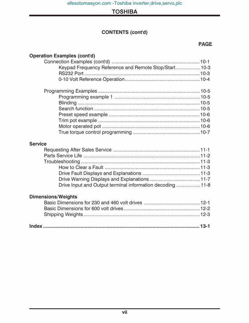
Operation Examples (cont'd)Connection Examples (cont'd) ..................................................................10-1
Keypad Frequency Reference and Remote Stop/Start ..................10-3RS232 Port ......................................................................................10-30-10 Volt Reference Operation........................................................10-4
Programming Examples ............................................................................10-5Programming example 1 ................................................................10-5Blinding ...........................................................................................10-5Search function ...............................................................................10-5Preset speed example ....................................................................10-6Trim pot example ............................................................................10-6Motor operated pot .........................................................................10-6True torque control programming ..................................................10-7
ServiceRequesting After Sales Service .................................................................11-1Parts Service Life .......................................................................................11-2Troubleshooting .........................................................................................11-3
How to Clear a Fault .......................................................................11-3Drive Fault Displays and Explanations ...........................................11-3Drive Warning Displays and Explanations ......................................11-7Drive Input and Output terminal information decoding ..................11-8
Dimensions/WeightsBasic Dimensions for 230 and 460 volt drives ..........................................12-1Basic Dimensions for 600 volt drives .........................................................12-2Shipping Weights.......................................................................................12-3
Index ................................................................................................................. 13-1
efesotomasyon.com -Toshiba inverter,drive,servo,plc

TOSHIBA
1 - 1
Inspection of the New DriveUpon receipt, inspect the drive for shipping damage. After uncrating:1) Check the unit for loose, broken, bent or otherwise damaged parts due to
shipping.
2) Check to see that the rated capacity and the model number specified on thenameplate conform to the order specifications.
Storage1) Store in a well ventilated location and preferably in the original carton if the
inverter will not be used immediately after purchase.
2) Avoid storage in locations with extreme temperatures, high humidity, dust, ormetal particles.
DisposalPlease contact your state environmental agency for details on disposal of electrical componentsand packaging in your particular area. Never dispose of electrical components viaincineration.
efesotomasyon.com -Toshiba inverter,drive,servo,plc

TOSHIBA
2 - 1
CAUTION Insp
ectio
n &
Prec
autio
nsO
pera
ting
Spec
ifica
tions
Wiri
ngEq
uipm
ent
Term
inal
Con
nect
ions
Ope
ratio
nPa
nel
Ope
ratin
gM
odes
Para
met
erSp
ecifi
catio
nsPa
ram
eter
Expl
anat
ions
Ope
ratio
nEx
ampl
esSe
rvic
e &
Trou
bles
hoot
Dim
ensi
ons
&W
eigh
tsIn
dex
Ref
eren
ce
Installation Safety Precautions
1) Always ground the unit to prevent electrical shock and to help reduceelectrical noise. A separate ground cable should be run inside the conduitwith the input, output, and control power cables (See Grounding page 4-7).
THE METAL OF CONDUIT IS NOT AN ACCEPTABLE GROUND.
2) Only qualified personnel should install this equipment (see General SafetyInstructions on page iii).
3) Installation of drive systems should conform as a minimum, to the 1996 NEC NationalElectrical Code Article 110 "Requirements For Electrical Installations", to all allregulations of the Occupational Safety and Health Administration, and to any otherapplicable national, regional or industry codes and standards.
4) Install in a secure and upright position in a well ventilated location that is out ofdirect sunlight. The ambient temperature should be between -10° C and 40° C.
5) Allow a clearance space of 8 inches (20 cm) for the top and bottom and 2 inches(5 cm) on both sides. For models 2010-2270 and models 4015-4500, the top and bottomclearance can be reduced to 4 inches (10 cm). This space will insure adequate ventilation.Do not obstruct any of the ventilation openings.
6) Avoid installation in areas where vibration, heat, humidity, dust, fibers, steel particles,explosive mists, gasses or sources of electrical noise are present.
7) Adequate working space and illumination must be provided for adjustment, inspectionand maintenance of the drive (see 1996 NEC Article 110-16).
8) A noncombustible insulating floor or mat should be provided in the areaimmediately surrounding the electrical system where maintenance is required.
9) Use lockout/tagout procedures on branch circuit disconnect before drive installation.
10) Connect three phase power of the correct voltage to input terminals L1, L2, L3 (R, S, T)and connect three phase power from output terminals T1, T2, T3 (U, V, W) to a motor ofthe correct voltage and type for the application. Size the branch circuit conductors inaccordance with Selection of Main Circuit Wiring Equipment and Standard Cable SizesPage 4-5.
11) If conductors of a smaller than recommended size are used in parallel to sharecurrent then the conductors should be kept together in sets i.e. U1, V1, W1 inone conduit and U2, V2, W2 in another (see 1996 NEC Article 300-20 and Article 310-4).National and local electrical codes should be checked for possible cable derating factorsif more than three power conductors are run in the same conduit (see 1996 NECArticle 310 adjustment factors on page 70-196).
12) Install a molded case circuit breaker (MCCB) between the power source and theinverter. Size the MCCB to clear the available fault current of the power source(see 1996 NEC Article 430 Article 102 through Article 111).
efesotomasyon.com -Toshiba inverter,drive,servo,plc

TOSHIBA
2 - 2
CAUTION
CAUTION
DANGER
Installation Safety Precautions (cont'd)
13) Use separate metal conduits for routing the input power, output power, andcontrol circuits.
14) If the factory provided door or NEMA 1 enclosure is removed from the drive, then itmust be provided with an alternate enclosure before operating. The alternate enclosureshould be a minimum of NEMA 1.
15) Do not connect control circuit terminal block return connections marked CC toinverter earth ground terminals marked GND(E). See Standard ConnectionDiagrams page 4-1 and Terminal Connections and Functions page 5-3.
16) If a secondary Magnetic Contactor (MC) is used between the inverter outputand the load, it should be interlocked so the ST-CC terminals are disconnectedbefore the output contactor is opened. If the output contactor is used for bypassoperation, it must also be interlocked so that commercial power is never appliedto the inverter output terminals (U,V,W).
17) Power factor improvement capacitors or surge absorbers must not be installedon the inverter's output.
Operating Safety Precautions
1) Do not touch any internal part with powerapplied to the inverter; first remove the power
supply from the drive and wait until charge LED (see page 5-1 for location) is no longerilluminated. Charged capacitors can present a hazard even if source power isremoved. not touc h any internal part with
power applied to the inverter. First remove the sou
2) DO NOT OPERATE THIS UNIT WITH ITS CABINET DOOR OPEN.
3) Only qualified personnel should have access to the adjustments and operation of thisequipment. They should be familiar with the drive operating instructions and withthe machinery being driven.
4) Only properly trained and qualified personnel should be allowed to servicethis equipment. See page iii.
5) Follow all warnings and precautions. Do not exceed equipment ratings.
6) Do not power up the inverter until this entire operation manual is reviewed.
7) The input voltage must be within +/-10% of the specified input voltage. Voltagesoutside of this permissible tolerance range may cause internal protectiondevices to turn on or can cause damage to the unit. Also, the input frequencyshould be within +/-2 Hz of the specified input frequency.
efesotomasyon.com -Toshiba inverter,drive,servo,plc

TOSHIBA
2 - 3
Operating Safety Precautions (cont'd)
8) Do not use this inverter with a motor whose rated input is greater than the ratedinverter output.
9) This inverter is designed to operate NEMA B motors. Consult the factory beforeusing the inverter for special applications such as an explosion proof motor orone with a repetitive type piston load.
10) Do not apply commercial power to the output terminals T1 (U), T2 (V), or T3(W) even if the inverter source power is off. Disconnect the inverter from themotor before megging or applying bypass voltage to the motor.
11) Interface problems can occur when this drive is used in conjunction withsome types of process controllers. Signal isolation may be required toprevent controller and/or drive malfunction (contact Toshiba or the processcontroller manufacturer for additional information about compatibility andsignal isolation).
12) Do not open and then re-close a secondary magnetic contactor (MC) betweenthe drive and the load unless the drive is OFF (output frequency hasdropped to zero) and the motor is not rotating. Abrupt re-application of theload while drive is on or while motor is rotating can cause drive damage.
13) Use caution when setting output frequency. Overspeeding a motor can decrease itstorque-developing ability and can result in damage to the motor and/or drivenequipment.
14) Use caution when setting the acceleration and deceleration time. Unnecessarilyshort times can cause tripping of the drive and mechanical stress to loads.
Confirmation of Wiring
Make the following final checks before applying power to the unit:
1) Confirm that source power is connected to terminals L1, L2, L3 (R, S, T).Connection of incoming source power to any other terminals will damagethe drive.
2) The 3-phase source power should be within the correct voltage and frequencytolerances.
3) The motor leads must be connected to terminals T1, T2, T3 (U, V, W).
4) Make sure there are no short circuits or inadvertent grounds and tighten anyloose connector terminal screws.
CAUTION Insp
ectio
n &
Prec
autio
nsO
pera
ting
Spec
ifica
tions
Wiri
ngEq
uipm
ent
Term
inal
Con
nect
ions
Ope
ratio
nPa
nel
Ope
ratin
gM
odes
Para
met
erSp
ecifi
catio
nsPa
ram
eter
Expl
anat
ions
Ope
ratio
nEx
ampl
esSe
rvic
e &
Trou
bles
hoot
Dim
ensi
ons
&W
eigh
tsIn
dex
Ref
eren
ce
CAUTION
efesotomasyon.com -Toshiba inverter,drive,servo,plc

TOSHIBA
2 - 4
CAUTION
CAUTION
Start-Up and Test
Prior to releasing an electrical drive system for regular operation after installation,the system should be given a start-up test by qualified personnel. This assurescorrect operation of the equipment for reasons of reliable and safe performance. It isimportant to make arrangements for such a check and that time is allowed for it.
When power is applied for the first time, the drive automatically starts up in the frequency monitorfunction of standard monitor mode with the 'default' parameters set as shown in the "FACTORYSETTING" column of the parameter tables starting on page 8-1. If these settings are not optimalfor the application, program the desired settings before initiating a run. The drive can beoperated with no motor connected. Operation with no motor connected or use with a small trialmotor is recommended for initial adjustment or for learning to adjust and operate the drive.
Maintenance
1) Use power lockout/tagout procedures on the disconnecting means in accordancewith applicable electrical codes (see 1996 NEC Article 430-101) before performing anydrive maintenance.
2) Periodically check the operating drive for cleanliness.
3) Do not use liquid cleaning agents.
4) Keep the heatsink free of dust and debris.
5) Periodically check electrical connections for tightness (with power off,locked out, and with charge LED extinguished (see page 5-1 for location) ).
efesotomasyon.com -Toshiba inverter,drive,servo,plc

TOSHIBA
3 - 1
Insp
ectio
n &
Prec
autio
nsO
pera
ting
Spec
ifica
tions
Wiri
ngEq
uipm
ent
Term
inal
Con
nect
ions
Ope
ratio
nPa
nel
Ope
ratin
gM
odes
Para
met
erSp
ecifi
catio
nsPa
ram
eter
Expl
anat
ions
Ope
ratio
nEx
ampl
esSe
rvic
e &
Trou
bles
hoot
Dim
ensi
ons
&W
eigh
tsIn
dex
Ref
eren
ce
MO
DE
L
230 Volt NEMA Type 1 Chassis Standard Ratings
NO
TE
S(s
ee b
elow
)
E3
RATED MOTOR OUTPUT DCL DCL OUTPUT OVERLOAD MAIN CIRCUITKVA HP(KW) CURRENT INDUCTOR CURRENT VOLTAGE CURRENT INPUT POWER
(AMPS) (mH) (A) 3-PHASE2035 (1) 3.5 3/2.2 9.6 NA NA 200-230V 110% FOR 200V/50Hz or2055 (1) 5.5 5/3.7 15.2 NA NA 3-PHASE 60 SEC. 200-230V/60Hz2080 (1) 8 7.5/5.5 22 ** 0.4 30 MAXIMUM 100% VOLTAGE:+/-10%2110 (1) 11 10/7.5 29 ** 0.2 38 VOLTAGE CONTINUOUS FREQ:+/-2Hz2160 (1) 16 15/11 42 ** 0.2 572220 (1) 22 20/15 56 * 0.2 762270 (1) 27 25/18 71 * 0.1 1142330 (1) 33 30/23 84 * 0.1 1142400 (1) 40 40/30 96 NA NA2500 (1) 50 50/37 124 NA NA2600 (1) 60 60/45 156 NA NA
STANDARD RATINGS
STANDARD RATINGS
NO
TE
S(s
ee b
elow
MO
DE
L
RATED MOTOR OUTPUT DCL DCL OUTPUT OVERLOAD MAIN CIRCUITKVA HP(KW) CURRENT INDUCTOR CURRENT VOLTAGE CURRENT INPUT POWER
(AMPS) (mH) (A) 3-PHASE 4055 (1) 5.5 5/3.7 7.6 ** 2.5 11 380-460V 110% FOR 380V/50Hz or4080 (1) 8 7.5/5.5 11 ** 1.8 15 3-PHASE 60 SEC. 400-460V/60Hz4110 (1) 11 10/7.5 14 ** 1.3 20 MAXIMUM 100% VOLTAGE:+/-10%4160 (1) 16 15/11 21 ** 0.9 29 VOLTAGE CONTINUOUS FREQ:+/-2Hz4220 (1) 22 20/15 27 ** 0.7 394270 (1) 27 25/18.5 34 *** 0.5 504330 (1) 33 30/22 40 *** 0.5 554400 (1) 40 40/30 52 *** 0.4 754500 (1) 50 50/37 65 *** 0.3 884600 (1) 60 60/45 77 *** 0.2 1144750 (1) 75 75/55 96 *** 0.2 141410K (1) 100 100/75 124 *** 0.15 175412K (1) 125 125/90 156 *** 0.23 220
460 Volt NEMA Type 1 Chassis Standard Ratings
STANDARD RATINGS
NO
TE
S(s
ee b
elow
)
MO
DE
L RATED MOTOR OUTPUT DCL DCL OUTPUT OVERLOAD MAIN CIRCUITKVA HP(KW) CURRENT INDUCTOR CURRENT VOLTAGE CURRENT INPUT POWER
(AMPS) (mH) (A) 3-PHASE6060 (1) 6 5 (3.8) 6.1 * 2.5 11 600V 150% FOR 575-600V/60Hz6120 (1) 12 10(7.5) 12 * 0.9 29 3-PHASE 120 SEC. 525V/50Hz6160 (1) 16 15(11) 17 * 0.9 29 MAXIMUM 110% VOLTAGE:+/-10%6220 (1) 22 20(15) 22 * 0.7 39 VOLTAGE CONTINUOUS FREQ:+/-2Hz6270 (1) 27 25(18.5) 27 * 0.5 556330 (1) 33 30(22) 32 * 0.5 506400 (1) 40 40(30) 41 * 0.4 756500 (1) 50 50(37) 52 * 0.4 756600 (1) 60 60(45) 62 * 0.3 886750 (1) 75 75(55) 77 * 0.2 114610K (1) 100 100(75) 99 * 0.2 141612K (1) 125 125(90) 125 * 0.15 175 130% FOR
120 SEC.110%
CONTINUOUS
600 Volt NEMA TYPE 1 Standard Enclosure Ratings
NOTES:1) UL/CUL (Underwriters Laboratories Inc.) listed.* Internal option** External option*** Standard internal feature
E3
E3
efesotomasyon.com -Toshiba inverter,drive,servo,plc

TOSHIBA
Principal Control System Sinusoidal PWM controlControl Output voltage regulation Same as power line.
Specifications Output frequency 0.01 to 400 Hz (0.1 to 80Hz default setting)*. 800 Hz operationpossible.
Frequency setting 0.1Hz from operating panel input (60Hz base), 0.01Hz from analoginput (60Hz base, 12-bit/0 to 10Vdc), 0.01Hz from computer interface(60Hz base)
Frequency accuracy Analog input: ±0.2% of the maximum output frequency (25°C±10°C),Digital input: ±0.01% (25°C±10°C)
Voltage/frequency Constant V/f, variable torque, automatic torque boost, True Torquecharacteristics Control and automatic energy-saving control/maximum voltage
frequency adjustment (25 to 400Hz), torque boost adjustment(0 to 30%), start-up frequency adjustment (0 to 10Hz).
PWM carrier frequency Adjustable between 0.5 and 15kHz, self adjustingTransistor type Insulated gate bipolar (IGBT)Output voltage regulation Drive can be programmed to fix max. output volts, let max. float with
input voltage, or set max. to input voltage sensed at power-up.Dynamic braking Feature not available in E3 drives above 30 HP.
Frequency Input signals 3k ohms potentiometer (1k ohm to 10k ohm-rated potentiometercan be connected). 0 to 10Vdc (Zin=33k ohm), ±10 Vdc (Zin=67kohm), +/-5 Vdc (Zin=34k ohm), 4 to 20mAdc (Zin=500 ohm)
Set point control (PID) Proportional gain, integral gain, anti-hunting gain, lag time constant,and PID error limit adjustments.
Operating Accel/decel time 0.1 to 6000 secs, accel/decel time 1 or 2 selection, accel/decelfunctions pattern selection
Forward or reverse run Forward run when F-CC closed (default); reverse run when R-CCclosed (default); reverse run when both closed (default); coast-stopwhen ST-CC opened (default); emergency coast stop by acommand from operating panel or terminal block; 3-wire control andmotorized speed pot programmable functions.
Jogging run Jog run from panel with JOG mode selection. Terminalblock operation possible with parameter settings.
Multispeed run Set frequency plus 15 preset speeds possible with combinations ofCC, SS1, SS2, SS3, and SS4.
Retry When a protective function is activated, the system checks maincircuit devices, and attempts to restart. Settable to a maximumof 10 times; wait time adjustment (0 to 10 secs)
Soft stall Automatic load reduction during overload (Default setting: OFF).Automatic restart A coasting motor can be smoothly restarted (Default setting: OFF).Pattern Run 4 groups of 8 patterns each can be set to the 15 preset speed values.
A maximum of 32 different patterns can be run; terminal blockcontrol/repetitive run possible.
DC injection braking Braking starting frequency adjustment (0 to 120Hz), braking currentadjustment (0 to 100%), braking time adjustment (0 to 10secs),emergency stop braking function, motor shaft stationary control.
Upper/Lower limit Limits the frequency between the set values (0 to max. frequency).Can be indicated via output contact closure.
Frequency jump 3 jump frequency settings (each with unique band settings)Edit function Easy access user group containing all changed parametersBlind function Select to display needed parameter groups and parametersUser-defined defaults User's parameter values can be saved into a default library. User
can then default drive to Toshiba's values or to the user's own.
3 - 2
* Consult the factory for applications above 80 Hz.
ITEM STANDARD SPECIFICATIONS
Standard Specifications
efesotomasyon.com -Toshiba inverter,drive,servo,plc

TOSHIBA
3 - 3
ITEM STANDARD SPECIFICATIONS
Standard Specifications (cont'd) Insp
ectio
n &
Prec
autio
nsO
pera
ting
Spec
ifica
tions
Wiri
ngEq
uipm
ent
Term
inal
Con
nect
ions
Ope
ratio
nPa
nel
Ope
ratin
gM
odes
Para
met
erSp
ecifi
catio
nsPa
ram
eter
Expl
anat
ions
Ope
ratio
nEx
ampl
esSe
rvic
e &
Trou
bles
hoot
Dim
ensi
ons
&W
eigh
tsIn
dex
Ref
eren
ce
Display Interface 4-digit, 7-segment LEDsFault display Overcurrent, overvoltage, heatsink overheat, load-side short-circuit,
load-side ground fault, inverter overload, stator overcurrent duringstart-up, load-side overcurrent during start-up, EEPROM error, RAMerror, ROM error, communication error, (dynamic braking unitovercurrent/overload), (emergency stop), (undervoltage), (lowcurrent), (overtorque), (open output phase), (motor overload). Itemsin parenthesis can be selected or deselected.
Monitor functions Terminal input/output status, forward/reverse, frequency settingvalue, output frequency, output current, output voltage, input power,output power, torque current, cumulative run time, past faults,excitation current, DBR overload ratio, inverter overload ratio, motoroverload ratio, PID feedback value, DC voltage.
Selectable units display Can scale frequency display.Selection of display of current in amps or %, voltage in V or %.
LED charge indicator Indicates that the main circuit capacitors are chargedLED local/remote Mounted in LOCAL/REMOTE key. Indicates local (keypad) orindicator remote (terminal) control.LED manual/auto Mounted in MANUAL/AUTO key. Indicates manual (keypad) orindicator auto (terminal) run command.
Inverter/Motor Protective functions Soft-stall, current limit, overcurrent, overvoltage, short-circuit at load,load-side ground fault, undervoltage, momentary power failure,regeneration power ride-through, electronic thermal overloadprotection, main circuit overcurrent at start-up, load-side overcurrentduring start-up, DBR resistor overcurrent/overload, heatsink overheat, emergency stop, open output phase.
Electronic thermal Drive's motor overload protection for motor can be adjusted for motorcharacteristics rated amperage. Motor overload has adjustable speed sensitivity.
Soft stall on/off. Motor 110% time programmable.Reset Fault reset via keypad, remote contact closure, or programming drive
retry. Cycling power also resets fault (fault display can be maintained)Regeneration power Some E3 ratings can use regen energy from motor to maintainride-through control operation during brown-outs.
Output signals Fault detection signal NC/NO form C contact (250VDC, 2A)Low output signal Dry contacts (250VDC, 2A)Reach output signal Open collector output (max. 24 Vdc, 50mA)Programmable meter Pre-compensation reference frequency, post-compensation outputoutput signals frequency, frequency setting value, output current, DC voltage,
output voltage, torque current, excitation current, PID feedback value,motor/inverter/DBR overload ratio, input/output power.
Pulse-train frequency Open collector output (max. 24 Vdc, 50mA)Communication functions RS232C equipped as standard ( connector: modular 6P), RS485, DN,
TOSLINE-F10, TOSLINE-F20, RIO, METASYS, & MB+ are options.Enclosure Type NEMA Type 1
Cooling method Forced air cooling . Fan can be automatically stopped when notnecessary for extended fan life.
Color Sherwin Williams Precision Tan #F63H12Service environment Indoor. Consult factory for elevations above 1000m (requires derate).
For example, at 2000m, derate drive FLA by 11%.Must not be exposed to direct sunlight, corrosive and/or explosivegases or mists, fibers and dusts.
Ambient temperature From -10°C to 40°C (14°F to 104°F).Relative humidity 20 to 95% maximum (non-condensating)Vibration 5.9 m/s (0.6G) maximum (10 to 55Hz)Climatic class 3K3Polution degree 2IP rating 2X
2
efesotomasyon.com -Toshiba inverter,drive,servo,plc

TOSHIBA
Standard Connection Diagrams
4 - 1
TOSVERT-130E3STANDARD CONNECTION
MODEL 2035 TO 2330
NOTES:
1.) For drive models 2035 through 2330 use 3-phase input power supply of 200VAC, 50Hzor 200-230VAC, 60Hz.
2.) Terminal ST and S4 are set to factory (default) and must be connected to CC for the driveto run. Jumpers connections to CC are installed by the factory. These terminals can beused as emergency stop by breaking the connection such as through a normally closedrelay contact. All input terminals can be programmed for other functions and maynot necessarily function as emergency off. In these cases remove the jumpers.(See Terminal Selection Parameters on page 9-7and 9-11)
3.) The S4 input terminal is shown above as an EMERGENCY OFF. When the drive isemergency stopped by breaking this connection it will not restart by making thisconnection.
efesotomasyon.com -Toshiba inverter,drive,servo,plc

TOSHIBA
4 - 2
TOSVERT-130E3STANDARD CONNECTION
MODEL 4055 TO 4220
Standard Connection Diagrams (cont'd) Insp
ectio
n &
Prec
autio
nsO
pera
ting
Spec
ifica
tions
Wiri
ngEq
uipm
ent
Term
inal
Con
nect
ions
Ope
ratio
nPa
nel
Ope
ratin
gM
odes
Para
met
erSp
ecifi
catio
nsPa
ram
eter
Expl
anat
ions
Ope
ratio
nEx
ampl
esSe
rvic
e &
Trou
bles
hoot
Dim
ensi
ons
&W
eigh
tsIn
dex
Ref
eren
ce
NOTES:
1.) For drive models 4055 through 4220 use input power supply of 380VAC, 50Hz or400-460VAC, 60Hz.
2.) Terminal ST and S4 are set to factory (default) and must be connected to CC for the driveto run. Jumpers connections to CC are installed by the factory. These terminals can beused as emergency stop by breaking the connection such as through a normally closedrelay contact. All input terminals can be programmed for other functions and maynot necessarily function as emergency off. In these cases remove the jumpers.(See Terminal Selection Parameters on page 9-7and 9-11)
3.) The S4 input terminal is shown above as an EMERGENCY OFF. When the drive isemergency stopped by breaking this connection it will not restart by making thisconnection.
efesotomasyon.com -Toshiba inverter,drive,servo,plc

TOSHIBA
Standard Connection Diagrams (cont'd)
4 - 3
TOSVERT-130E3STANDARD CONNECTION
MODEL 4270 TO 4500
NOTES:
1.) For drive models 4270 through 4500 use input power supply of 380VAC, 50Hz or400-460VAC, 60Hz.
2.) Terminal ST and S4 are set to factory (default) and must be connected to CC for the driveto run. Jumpers connections to CC are installed by the factory. These terminals can beused as emergency stop by breaking the connection such as through a normally closedrelay contact. All input terminals can be programmed for other functions and maynot necessarily function as emergency off. In these cases remove the jumpers.(See Terminal Selection Parameters on page 9-7and 9-11)
3.) The S4 input terminal is shown above as an EMERGENCY OFF. When the drive isemergency stopped by breaking this connection it will not restart by making thisconnection.
efesotomasyon.com -Toshiba inverter,drive,servo,plc

TOSHIBA
Standard Connection Diagrams (cont'd)
4 - 4
Insp
ectio
n &
Prec
autio
nsO
pera
ting
Spec
ifica
tions
Wiri
ngEq
uipm
ent
Term
inal
Con
nect
ions
Ope
ratio
nPa
nel
Ope
ratin
gM
odes
Para
met
erSp
ecifi
catio
nsPa
ram
eter
Expl
anat
ions
Ope
ratio
nEx
ampl
esSe
rvic
e &
Trou
bles
hoot
Dim
ensi
ons
&W
eigh
tsIn
dex
Ref
eren
ce
TOSVERT-130E3STANDARD CONNECTION
MODEL 4600 TO 412K& MODEL 2400 TO 2600
See Note 3
NOTES:
1.) Terminal ST and S4 are set to factory (default) and must be connected to CC for the driveto run. Jumpers connections to CC are installed by the factory. These terminals can beused as emergency stop by breaking the connection such as through a normally closedrelay contact. All input terminals can be programmed for other functions and maynot necessarily function as emergency off. In these cases remove the jumpers.(See Terminal Selection Parameters on page 9-7and 9-11)
2.) The S4 input terminal is shown above as an EMERGENCY OFF. When the drive isemergency stopped by breaking this connection it will not restart by making thisconnection.
3.) Input power selection terminals not applicable in Models 2400 to 2600.
efesotomasyon.com -Toshiba inverter,drive,servo,plc

TOSHIBA
4 - 5
Standard Connection Diagrams (cont'd)
TOSVERT-130E3STANDARD CONNECTION
MODEL 6060 TO 612K
DBR
PBPAL1(R)L2 (S)
L3 (T)
PROGRAMMABLESIGNAL INPUT
PROGRAMMABLEANALOG INPUT
R/CH-C
FLC
FLA
+
+
S1
PP
RR
AUTOREF.
AUTOREF.
-
-
T3 (W)
T1(U)
T2 (V)
PROGRAMMABLEOUTPUT CONTACTS250V, 2A MAX
PROGRAMMABLEOUTPUT CONTACTS250V, 2A MAX
AM FM
PROGRAMMABLESIGNAL OUTPUT0-1mA or 4-20mA
M
MR60
R57
R52
RJ
RESF
R
ST
MCCB
CC
R/CH-A
LOW-A
LOW-C
P24
FP
FM
AM
CC
PULSE OUTPUT
50mA MAX
GND(E)
DIGITALOPERATION PANEL
CC
IV
RX
(see note 1 below) S4
++
FLB
S3
S2
INPUT POWER SUPPLY(set by input power selection)
INPUT POWER SELECTION600V-60Hz575V-60Hz525V-50Hz
NOTES:
1.) Terminal ST and S4 are set to factory (default) and must be connected to CC for the driveto run. Jumpers connections to CC are installed by the factory. These terminals can beused as emergency stop by breaking the connection such as through a normally closedrelay contact. All input terminals can be programmed for other functions and maynot necessarily function as emergency off. In these cases remove the jumpers.(See Terminal Selection Parameters on page 9-7and 9-11)
2.) The S4 input terminal is shown above as an EMERGENCY OFF. When the drive isemergency stopped by breaking this connection it will not restart by making thisconnection.
Potentiometer
efesotomasyon.com -Toshiba inverter,drive,servo,plc

TOSHIBA
4 - 6
Selection of Main Circuit Wiring Equipment and Standard Cable Sizes
3-core shield cable #18 (speed reference)2-core shield cable
#20
Insp
ectio
n &
Prec
autio
nsO
pera
ting
Spec
ifica
tions
Wiri
ngEq
uipm
ent
Term
inal
Con
nect
ions
Ope
ratio
nPa
nel
Ope
ratin
gM
odes
Para
met
erSp
ecifi
catio
nsPa
ram
eter
Expl
anat
ions
Ope
ratio
nEx
ampl
esSe
rvic
e &
Trou
bles
hoot
Dim
ensi
ons
&W
eigh
tsIn
dex
Ref
eren
ce
* Molded case AmpacityDrive circuit breaker (FLA x 1.25) ** Typical cable size (AWG)
(MCCB)
Amp Main power Input / Output Frequency command input, OtherModel Number rating (A) and Lug frequency meter, ammeter signal
(A) motor load Wire Capacity circuits
E3-2035 20 12 #14 24-12 / 24-12
E3-2055 30 19 #14 24-12 / 24-12
E3-2080 50 28 #10 24-8 / 24-8
E3-2110 70 37 #8 24-8 / 24-8
E3-2160 90 53 #6 18-2 / 18-2
E3-2220 100 70 #4 18-2 / 18-2
E3-2270 125 89 #3 14-2 / 14-2
E3-2330 150 105 #2 14-2 / 14-2
E3-2400 175 120 #1 6-250 / 6-250
E3-2500 175 155 #2/0 6-250 / 6-250
E3-2600 200 195 #3/0 6-250 / 6-250
E3-4055 15 10 #14 24-12 / 24-12
E3-4080 30 14 #14 24-12 / 24-12
E3-4110 30 18 #14 24-12 / 24-12
E3-4160 40 27 #10 24-8 / 24-8
E3-4220 50 34 #10 24-8 / 24-8
E3-4270 70 43 #8 14-2 / 18-2
E3-4330 90 50 #6 14-2 / 18-2
E3-4400 100 65 #4 14-2 / 18-2
E3-4500 100 82 #4 14-2 / 18-2
E3-4600 125 97 #3 6-250 / 6-250
E3-4750 175 120 #1 6-250 / 6-250
E3-410K 175 155 #2/0 6-250 / 6-250
E3-412K 200 195 #3/0 6-250 / 6-250
E3-6060 15 8 #14 24-12 / 24-12
E3-6120 30 15 #14 24-12 / 24-12
E3-6160 35 22 #12 14-2 / 18-2
E3-6220 50 28 #10 14-2 / 18-2
E3-6270 60 34 #8 14-2 / 18-2
E3-6330 70 40 #8 6-250 / 18-2
E3-6400 90 52 #6 6-250 / 18-2
E3-6500 100 65 #4 6-250 / 18-2
E3-6600 100 78 #3 6-250 / 6-250
E3-6750 125 97 #2 6-250 / 6-250
E3-610K 175 124 #1/0 6-250 / 6-250
E3-612K 200 157 #2/0 6-250 / 6-250
See page 4-7 for notes.
efesotomasyon.com -Toshiba inverter,drive,servo,plc

TOSHIBA
4 - 7
Selection of Main Circuit Wiring Equipment and Standard Cable Sizes (cont'd)
* A customer supplied disconnect means must be provided in the motor branch circuitwhich supplies power to the drive. It can be separate for use with customer suppliedfuses or it can be an integral part of a customer supplied 3-pole circuit breaker (see 1996NEC Article 430-103 through 430-113). All drives in this series are rated for output shortcircuit fault currents of 200,000A. The selection of MCCB (molded case circuit breaker)for this table is in accordance with 1996 NEC Article 430-51, 430-52, 430-152, and 240-6.
** Wire sizing is based upon NEC table 310-16 or CEC Table 2 using 75 deg C cable, anambient of 30 deg C, cable runs for less than 300 FT., and copper wiring for not morethan three conductors in raceway or cable or earth (directly buried). The customershould consult the NEC or CEC wire Tables for his own particular application andwire sizing.
*** Use two parallel conductors instead of a single conductor (this will allow for the properwire bending radius within the cabinet). Use separate conduits for routing parallelconductors. This prevents the need for conductor derating (see note 3 this page).
Notes:
1.) Contacts used to connect drive terminals should be capable of switching lowcurrent signals (i.e. 5 mA).
2.) The drive has internal motor overload protection which has been functionallycertified by Underwriters Laboratories Inc. and no additional external motoroverload protection is required (see 1996 NEC Article 430-32 and 430-39).
3.) When wiring with parallel conductors, the conductors should be kept togetherin phase sets to avoid heating the surrounding metal by induction. InstallU1, V1, W1 conductors in one conduit and parallel conductors U2, V2, W2in another conduit. The ground conductor must be run in the same conduit.See 1996 NEC Article 300-20(a), 310-4, 310-5. Size the grounding conductorin accordance with 1996 NEC Table 250-95.
4) Twisted pair wiring should be used for external meters connected to AM and FMterminals.
5) For multiple motor applications, a thermal-magnetic circuit breaker must beinstalled between the drive and each motor. The thermal circuit is for overloadsensing and the magnetic coil is for abnormal conditions such as short circuits.Select the MCCB (molded case circuit breaker) in accordance with 1996 NECArticle 430-51 through 430-53, 430-152, and 240-6.
Turn off power to the drive before making any wiringchanges to the analog output circuits.
CAUTION
Use separate conduits for routing incoming power, powerto motor, and control conductors. Use no more than threepower conductors and a ground conductor per conduit.
CAUTION
efesotomasyon.com -Toshiba inverter,drive,servo,plc

TOSHIBA
4 - 8
CAUTION Conduit is not a suitable ground for the inverter.
Insp
ectio
n &
Prec
autio
nsO
pera
ting
Spec
ifica
tions
Wiri
ngEq
uipm
ent
Term
inal
Con
nect
ions
Ope
ratio
nPa
nel
Ope
ratin
gM
odes
Para
met
erSp
ecifi
catio
nsPa
ram
eter
Expl
anat
ions
Ope
ratio
nEx
ampl
esSe
rvic
e &
Trou
bles
hoot
Dim
ensi
ons
&W
eigh
tsIn
dex
Refe
renc
e
1
230 V
460 V
575 V
460 V
575 V
AC MotorVoltage
PWM CarrierFrequency 2
NEMA MG-1-1998 Section IVPart 31 Compliant Motors
1000 ft.
600 ft.
300 ft.
200 ft.
100 ft.
< = 5 kHz
> 5 kHz
< = 5 kHz
> 5 kHz
All
GroundingThe inverter must be grounded in accordance with Article 250 of the National ElectricalCode or Section 10 of the Canadian Electrical Code, Part I and the grounding conductorshould be sized in accordance with 1996 NEC Table 250-95 or CEC, Part I Table 16. SeeInstallation Safety Precautions notes 7 and 14.
Motor Selection1) Exceeding the peak voltage rating or the rise time allowable of the motor insulation
system will reduce the life expectancy. To insure good motor insulation life, consultwith the motor supplier as to determine motor insulation ratings and allowable maximumoutput lead distance. Long lead lenghts between the motor and the drive may requirefilters to be added to the drive output.
Suggested Maximum Output Lead Distance
2) Bearing Considerations:A. Motors operating from adjustable speed drive power sources tend to operate at
higher temperatures which may increase the need for more frequent lubricationcycles.
For lead lengths that exceed suggested maximum contact Toshiba for applicationassistance.
Toshiba EQP III, III-XS & EQP III-841 motors incorporate an insullation system thatis in compliance with NEMA MG-1-1998 Section IV Part 31.
1
2
efesotomasyon.com -Toshiba inverter,drive,servo,plc

TOSHIBA
5 - 1
Charge LED
Terminal Block
ST FM AM CC CC RX PP IV FP FLC FLB
P24 RES RR F R S1 S2 S3 S4 RCH LOWA
LOWC
Fused Resistor for P24
Terminal BoardThe terminal printed wiring board is shown in the detail below. See Terminal Connections andFunctions starting on page 5-3. This board is used in all drive sizes.
P24
FLA
CAUTION Turn off power to the drive before connecting ordisconnecting any wiring to the terminal block.
efesotomasyon.com -Toshiba inverter,drive,servo,plc

TOSHIBA
Control BoardThe control printed wiring board is shown in the detail below. This control board is used inall drive sizes.
5 - 2
RS-232Communication
connector
Dip SwitchSW1
(see detail 1this page)
I 5
10V
OptionROMsocket
Operationpanel
connector
Option boardconnector(40-pin)
Ribbon cableconnector
Ribbon cableconnector(back side) Dip Switch SW1
(Detail)
When a 0-1mA reference signal is input toterminal "IV", set switch SW1 to I
When a 0-10 volt reference signal is input toterminal "IV", set SW1 to V
When a +/- 0-5 volt reference signal is inputto terminal "RX", set SW1 to 5
When a +/- 0-10 volt reference signal isinput to terminal "RX", set SW1 to 10
Make connections to this board only with power off.
Insp
ectio
n &
Prec
autio
nsO
pera
ting
Spec
ifica
tions
Wiri
ngEq
uipm
ent
Term
inal
Con
nect
ions
Ope
ratio
nPa
nel
Ope
ratin
gM
odes
Para
met
erPa
ram
eter
Expl
anat
ions
Ope
ratio
nEx
ampl
esSe
rvic
e &
Trou
bles
hoot
Dim
ensi
ons
&W
eigh
tsIn
dex
Ref
eren
ceSp
ecifi
catio
ns
efesotomasyon.com -Toshiba inverter,drive,servo,plc

TOSHIBA
5 - 3
Terminalblock
orbus bar
Terminalblock
(See page5-1)(do not make/break
connection to thisterminal with drivepowered)
(do not make/breakconnection to thisterminal with drivepowered)
Terminal Connections and FunctionsTerminal Terminal functions Terminal
name location
L1, L2, L3 Line input supply terminals for models E3-2035 to E3-2330:(R, S, T) Connect to either 3ø, 50Hz, 200VAC or 3ø, 60Hz, 200 to 230VAC.
Line input supply terminals for models E3-4055 to E3-412K: Connect to either 3ø, 50HZ, 400VAC or 3ø, 60Hz, 400 to 460VAC.Line input supply terminals for models E3-6060 to E3-612K: Connect to either 3ø, 50HZ, 525VAC or 3ø, 60Hz, 575 to 600VAC.Drives can be operated on single phase power when appropriatelyderated; contact Toshiba distributor for information.
T1, T2, T3 Motor output terminals. Connect these terminals to a 3-phase(U, V, W) induction motor of the proper voltage, current, and horsepower.
PA, PB Braking resistor output terminals. Connect to an external dynamicbraking resistor (DBR) (available on all 230 and 600 volt drives andonly on 460 volt drives that are 20 HP and smaller).
FLA, FLB, FLC Programmable relay contact output. The contact rating is250VAC - 2A. Default setting closes FLA-FLC and opens FLB-FLCwhen protective function has been activated.
P24 Unregulated 24Vdc power supply (24Vdc, 50mA maximum). P24 is(two terminals) protected by fused resistor found on the terminal board (see p. 5-1).
RCH Programmable open collector output. Standard setting applies aground through the transistor when an acc/dec is complete, orwhen the output frequency is within a specified range.
LOW(A & C) Programmable relay contact output. Standard setting closescontact when a preset low speed or a preset lower limit isreached. Contact rating is 250Vac - 2A.
PP 10 VDC supply typically used to drive potentiometers. Wipers frompots typically connected to "RR" or "RX" terminals.
FM Programmable analog output. Outputs 0 - 1mA current. Thisterminal can be connected to an external analog meter. Use eitheran ammeter rated 1mA DC/20 mA DC at full scale or a voltmeterrated 7.5Vdc at full scale (true analog output).See page 9-31 for programming.
AM Programmable analog output. Outputs 0 - 1mA current. Thisterminal can be connected to an external analog meter. Use eitheran ammeter rated 1mA DC/20 mA DC at full scale or a voltmeterrated 7.5Vdc at full scale (true analog output).See page 9-31 for programming.
FP Dedicated open-collector output. Pulses that are 48, 96, or360-times the output frequency are available according to theparameter settings (must connect external supply through pull-upresistor to measure output).
CC This is the common return for all of the input and output terminals.(2-terminals) Do not connect this terminal to ground.
efesotomasyon.com -Toshiba inverter,drive,servo,plc

TOSHIBA
5 - 4
Insp
ectio
n &
Prec
autio
nsO
pera
ting
Spec
ifica
tions
Wiri
ngEq
uipm
ent
Term
inal
Con
nect
ions
Ope
ratio
nPa
nel
Ope
ratin
gM
odes
Para
met
erSp
ecifi
catio
nsPa
ram
eter
Expl
anat
ions
Ope
ratio
nEx
ampl
esSe
rvic
e &
Trou
bles
hoot
Dim
ensi
ons
&W
eigh
tsIn
dex
Ref
eren
ceTerminal
block(60HP andlarger 460Vmodels and
all 600Vmodels only)
Terminal Connections and Functions (cont'd)Terminal Terminal functions Terminal
name location
RR Programmable analog input. Default setting allows user toinput a 0 - 10VDC signal as a frequency command. Input hasbias/gain adjustments.
IV Programmable analog input. User can input a 0 - 10VDC signal or a4 - 20 mA DC signal as a frequency command (selection of currentor voltage done via dipswitch on control board (see page 5-2).Input has bias gain adjustments.
RX Programmable analog input. User can input a +/- 10VDC or a+/- 5VDC signal as a frequency command (see page 5-2). Inputhas bias/gain adjustments for forward and reverse operation.
ST Programmable digital input. With default setting, shorting terminalto "CC" enables drive. Opening "ST" to "CC" coasts motor.
F Programmable digital input. With default setting, shorting terminalto "CC" gives drive forward run command. Opening "F" to "CC"decels motor to a stop.
R Programmable digital input. With default setting, shorting terminalto "CC" gives drive reverse run command. Opening "R" to "CC"decels motor to a stop.
S1 Programmable digital input. With default setting, shorting "S1" to"CC" enables fire speed run.
S2 Programmable digital input. With default setting, shorting "S2" to"CC" disables feedback control.
S3 Programmable digital input. With default setting, shorting "S3" to"CC" gives drive preset speed frequency reference.
S4 Programmable digital input. With default setting, shorting "S4" to"CC" gives no emergency off command.
RES Programmable digital input. With default setting, shorting "RES" to"CC" resets a tripped drive.
R41/46 Input power selection. Shorting to "RJ" selects 415/460V-50/60Hz.
R40/44 Input power selection. Shorting to "RJ" selects 400/440V-50/60Hz.
R38 Input power selection. Shorting to "RJ" selects 380V-50Hz.
R60 Input power selection. Shorting to "RJ" selects 600V-60Hz.
R57 Input power selection. Shorting to "RJ" selects 575V-60Hz.
R52 Input power selection. Shorting to "RJ" selects 525V-50Hz.
RJ This is the common return for input power selection terminalsR41/46, R40/44, R38, R60, R57, and R52. Use only oneselection at a time. Do not connect to CC.
Terminalblock
(See page5-1)
efesotomasyon.com -Toshiba inverter,drive,servo,plc

TOSHIBA
6 - 1
Operating Panel LayoutThe operating panel enables the user to enable or disable the keypad, input commands fromthe keypad, and monitor drive operation. The illustration below shows the operating panel keypadlayout and the locations of the keys and display LED's.
Units LED(typical 4)
7- Segment LEDdisplay area
Keys(typical 8)
Local/Remote LEDManual/Auto LED
LED Display DescriptionA description of the LED display is given below:
1. 4 seven-segment LED character display.In standard monitor mode: displays the current output frequencyIn status monitor mode: monitors the status conditions and frequency command value
settingIn setup mode: displays setup parameter titles and valuesIn program mode: displays parameter group titles, individual parameter names, and
parameter valuesDuring a trip: displays the trip title
2. Local/Remote LEDsThe appropriate local/remote LED which is inset into the speed control key is lit when theunit is in local or remote mode.
3. Manual/Auto LEDsThe appropriate manual/auto LED which is inset into the run mode key is lit when theunit is manual or auto mode.
4. Units LEDsWhen numeric data is being displayed on the LED display, the corresponding unitindication LED will be lit. If no unit indication LED is lit, the current data has no unit orthe corresponding unit does not exist on the display panel.
efesotomasyon.com -Toshiba inverter,drive,servo,plc

TOSHIBA
6 - 2
7-Segment AlphanumericsThe 7 segment LED display has a limited number of output characters, therefore thefollowing figures and letters will be used for the display.
LED display
A
b
C
d
E
F
G
H
h
I
J
L
M
n
O
P
r
S
t
U
v
y
-
LED display
0
1
2
3
4
5
6
7
8
9
Numerics
0
1
2
3
4
5
6
7
8
9
v
Characters
A
b
C
c
d
E
F
G
H
h
I
J
L
M
n
O
P
q
r
S
t
U
v
y
-
b
Insp
ectio
n &
Prec
autio
nsO
pera
ting
Spec
ifica
tions
Wiri
ngEq
uipm
ent
Term
inal
Con
nect
ions
Ope
ratio
nO
pera
ting
Mod
esPa
ram
eter
Spec
ifica
tions
Para
met
erEx
plan
atio
nsO
pera
tion
Exam
ples
Serv
ice
&Tr
oubl
esho
otD
imen
sion
s &
Wei
ghts
Inde
xR
efer
ence
Pane
l
efesotomasyon.com -Toshiba inverter,drive,servo,plc

TOSHIBA
6 - 3
Key Function
Panel Keys and FunctionsThe following chart explains each of the key functions on the keypad
MANUAL/AUTO
RUN MODE
LOCAL/REMOTE
SPEED CTRL
RUN
Local/Remote KeySwitches the source of frequency command information from panel/terminalblock. The appropriate LED is lit to indicate local or remote frequency command.Local/Remote key will be referred to as L/R key in this specification.
Manual/Auto KeySwitches the source of run/stop command information from panel/terminal block.The appropriate LED is lit to indicate manual or auto run/stop command.
Setup/Program/Monitor KeyToggles between Setup, Program, Monitor, and Frequency Mode. The Setup/Program/Monitor key will be referred to as the S/P/M key in this specification.
SETUPPROGRAMMONITOR
READ
WRITE
Up KeyScrolls up the setting of the currently displayed parameter. If the key is helddown, the scrolling speed gradually increases. Only RAM values are changed.Also toggles to other function group entries. The up and down keys will bereferred to as the U/D key in this manual. Pushing R/W key saves the setting.
Down KeyScrolls down the setting of the currently displayed parameter. If the key is helddown, the scrolling speed gradually increases. Only RAM values are changed.Also toggles to other function group entries. The up and down keys will bereferred to as the U/D key in this manual. Pushing R/W key saves the setting.
Run KeyThis key is used to start a RUN command (only valid when in manual controlmode).
Stop/Reset KeyFunctions as the STOP key and emergency stop key during local operation.Functions as the RESET key when an inverter trip occurs. In all other modes,emergency off is engaged when this key is pressed twice.
STOPRESET
Keys and Functions
Read/Write KeyMode, group, parameter, data, and frequency selection key. This key is used toselect or enter a parameter value, a frequency command, or a group name. Theread/write key will be referred to as the R/W key in this manual.
efesotomasyon.com -Toshiba inverter,drive,servo,plc

TOSHIBA
7 - 1
MODE SUMMARY
Insp
ectio
n &
Prec
autio
nsO
pera
ting
Spec
ifica
tions
Wiri
ngEq
uipm
ent
Term
inal
Con
nect
ions
Ope
ratio
nO
pera
ting
Mod
esIn
dex
Ref
eren
cePa
nel
Para
met
erSp
ecifi
catio
nsPa
ram
eter
Expl
anat
ions
Ope
ratio
nEx
ampl
esSe
rvic
e &
Trou
bles
hoot
Dim
ensi
ons
&W
eigh
ts
Function Outline
The fundamental operation of the E3 LED display/keypad is as follows:
1. Standard monitor mode (Local/Remote, Manual/Auto, Host, Option)(Mode selection level) When the drive is initially powered up, it is in standard monitor mode.The drive will display the current output frequency, trip code, or warning code. The drive willaccept run/stop and frequency commands from the sources selected by the panel buttons orparameter settings. All appropriate panel LEDs will be lit to indicate frequency units,command mode, and frequency mode.
2. Setup mode2a. parameter selection2b. data selectionDrive SETUP parameters are read and modified in this mode. Setup parameters are themost fundamental parameters that nearly all users must edit to operate the drive.
3. Program Mode3a. group selection3b. parameter selection3c. data selectionAll parameters can be read and modified in this mode. Parameters are grouped accordingto functions. The parameter groups can be blinded/unblinded.
4. Status monitor modeDisplays operating conditions (frequency, current, voltage, etc.), terminal status, version, pasterror conditions, etc.
5. Meter adjustmentAllows the adjustment of an external analog output frequency or current meter.
Parameter Setting Function conditionFMOD = 0 XFMOD = 1 XFMOD = 2 OFMOD = 3 XFMOD = 4 O
Standard Monitor Mode/frequency monitor functionWhen power is applied, the drive automatically starts up in the frequency monitor function ofstandard monitor mode. In the frequency monitor function, the output frequency is displayed andcan be adjusted using the U/D keys. Pushing the S/P/M key again switches to the mode selectionmenu, and pushing the S/P/M key again toggles back to standard monitor mode.
Standard monitor mode - frequency command value settingThe local frequency command is adjusted by pushing the U/D keys while in standard monitormode. The S/P/M key will toggle back to the standard monitor mode.
NOTE: However, the ability to use this function is limited by the FMOD parameteras shown below (O=permissible, X=not permissible).
efesotomasyon.com -Toshiba inverter,drive,servo,plc

TOSHIBA
7 - 2
MODE SUMMARY
Standard Monitor Mode (cont'd)
The following example shows the frequency command value setting being changed from 0 Hz to60 Hz (assuming present conditions are: local control mode, standard monitor mode, and theinverter is not running).
Key Operation LED Message Explanation
0.0 Standard monitor mode (current output frequency displayed)XX.X Display changes to indicate that the frequency command
setting is displayed rather than the output frequency. Setting(press and hold) value gradually increases.
60.0 When the key is released, the value stops increasing and the(release UP key) *data blinking* new setting value will begin to blink to indicate that the
displayed value (RAM) has been changed from non-volatilememory value (EEPROM). (See note 1 page 7-2)
READ/WRITE FCÖ60.0 When the read/write key is pressed, the parameter name,FC, and the new setting value will be alternately displayed toindicate that the new local frequency command setting valuehas been written to memory (EEPROM & RAM). After twoalternating display cycles, the display will return to standardmonitor mode, with the output frequency displayed.
0.0 Standard monitor mode (current output frequency displayed)
NOTE 1: The frequency command value has been set to 60Hz, but the data has been changed only inRAM, and was not changed in the E2PROM. Under this condition, 60Hz operation can beachieved by the use of RUN and STOP keys, but if control power to the inverter is removed,the previous setting value (0.0Hz) will return.
If the frequency command value is changed during operation, the operating frequency will alsochange accordingly. If the command value precedes the actual operating frequency, theaccel/decel of the motor will be dictated by the accel/decel times.
READ/WRITE + Fr-F Indicates forward direction of motor operation
REAR/WRITE + Fr-r Indicates reverse direction of motor operation
LED Message
Standard monitor mode - switching between forward/reverse during operationIn standard monitor mode, the following key operations will allow switching between forward andreverse operation:
Key Operation Explanation
However, this switching can be done only while in manual control mode. The motor directionLED message is displayed while the key sequence is pressed and held. When the key sequenceis released the display returns to standard monitor mode with output frequency displayed(See note 2 this page)
NOTE 2: Reverse run can be disabled using the parameter DISR which is described in section“Fundamental Parameters #1” on page 8-2.
efesotomasyon.com -Toshiba inverter,drive,servo,plc

TOSHIBA
7 - 3
MODE SUMMARY
Insp
ectio
n &
Prec
autio
nsO
pera
ting
Spec
ifica
tions
Wiri
ngEq
uipm
ent
Term
inal
Con
nect
ions
Ope
ratio
nO
pera
ting
Mod
esPa
ram
eter
Spec
ifica
tions
Para
met
erEx
plan
atio
nsO
pera
tion
Exam
ples
Serv
ice
&Tr
oubl
esho
otD
imen
sion
s &
Wei
ghts
Inde
xR
efer
ence
Pane
l
Standard monitor mode - status alarmsIn standard monitor mode, there are five alarm conditions that will cause alarm messages to bedisplayed. The alarm message and the output frequency will be displayed simultaneously ifpossible and flashed alternately if not. The following five conditions will cause warning messagesto be displayed: overload, overvoltage, overcurrent, overheat, and communication timeout. Thealarm indicators will be displayed either singularly or in combination with other alarm indicators ifmultiple alarm conditions exist simultaneously. If the alarm condition(s) is removed, the alarmmessage will automatically be removed from the display.
Because these warning displays L Indicates overload conditionare automatic, no key input P Indicates overvoltage condition
C Indicates overcurrent conditionH Indicates overheat conditionT Indicates communication timeout conditionLC Indicates an overload and overcurrent conditionLCH Indicates overload, overcurrent, and overheat
conditions
Key Operation LED Message Explanation
SETP Setup mode selection
PrOG Program mode selection
MoN Status monitor mode selection
Each of these modes is described in more detail in the following sections.
ExplanationMode selections
Mode selection menuIf the S/P/M key is pressed while in standard monitor mode, the mode selection menu isdisplayed. This menu contains 3 selections: setup mode, program mode, and status monitormode. It is possible to scroll through the menu selections until the desired mode is displayed.The mode is selected by pressing the R/W key.
The following menu selections are available in the mode selection menu:
efesotomasyon.com -Toshiba inverter,drive,servo,plc

TOSHIBA
7 - 4
Key Operation LED Message Explanation
Setup modeSetup mode is a program group requested specifically for the HVAC industries. The setup groupis to provide simplified access to the most fundamental drive parameters that nearly every userwill access regularly. Setup mode is entered by selecting the SETP mode in the mode selectionmenu and pressing the READ key. It is then possible to scroll through the various setupparameters using the up/down keys and edit the desired parameters using the READ/WRITEand UP/DOWN keys. Pressing the S/P/M key will return the user to standard monitor mode.The following is an example of accessing and editing a setup parameter (starting from standardmonitor mode).
MODE SUMMARY
0.0 Standard monitor mode (current output frequency displayed)S/P/M SETP Display changes to the first entry in the mode selection menu,
SETP (SETUP mode).R/W ACC1 Display changes to the first entry in the setup parameter list,
ACC1 (Acceleration time #1).deC1 Assume we want to change upper limit frequency to 70.0 Hz.
Pressing the U/D keys scrolls through the list of setupUl parameter titles until Ul is displayed.
R/W 60.0 Pressing R/W selects the currently displayed parameter anddisplays its current setting value.
XX.X Setting value increases.
(press and hold)Release up key 70.0 Releasing the up key causes the setting value to stop
increasing. The data will flash to indicate that the displayedvalue (RAM) has been changed from the non-volatile memoryvalue.
R/W ULÖ70.0 When the read/write key is pressed, the parameter name, Ul,and the new setting value will be alternately displayed toindicate that the new setting value has been written tomemory. After two alternating display cycles, the display willreturn to setup mode, with the parameter title Ul displayed.
efesotomasyon.com -Toshiba inverter,drive,servo,plc

TOSHIBA
7 - 5
Explanation
ACC1 Acceleration time #1
DEC1 Deceleration time #1
UL Upper limit frequency
LL Lower limit frequency
sfly Local/Remote and Manual/Auto switch on the fly
iVin IV input selection
P3 IV reference point #1
F-P3 IV reference point #1 frequency
P4 IV reference point #2
F-P4 IV reference point #2 frequency
THR1 Motor overload rating
STC1 Stall selection
STL1 Stall level #1
OLM Motor overload selection
OLT Motor 110% overload time limit
APL Application parameters selection
TYP Standard setting mode
PASS Pass number
E3 setup parameter titles
Setup mode (cont'd)The following table lists the setup group parameter codes and the corresponding parameter title.
MODE SUMMARY
Insp
ectio
n &
Prec
autio
nsO
pera
ting
Spec
ifica
tions
Wiri
ngEq
uipm
ent
Term
inal
Con
nect
ions
Ope
ratio
nO
pera
ting
Mod
esPa
ram
eter
Spec
ifica
tions
Para
met
erEx
plan
atio
nsO
pera
tion
Exam
ples
Serv
ice
&Tr
oubl
esho
otD
imen
sion
s &
Wei
ghts
Inde
xR
efer
ence
Pane
l
efesotomasyon.com -Toshiba inverter,drive,servo,plc

TOSHIBA
7 - 6
Program ModeThe program mode is the standard interface for the drive parameters. The parameters aregrouped (and blinded) by function for easy reference. To switch to this mode while in standardmonitor mode, press the S/P/M key twice to select the program mode title PROG and press R/W.To escape from this mode, pushing the S/P/M key will switch back to the standard monitor mode.There are three main functions in this mode: the parameter display and setting function describedbelow, displaying and changing user changed parameters (page 7-8), and the analog outputadjustment function (page 7-9).
Program mode - parameter display and setting functionTo change parameter settings, perform the following process:1. Switch to program mode2. At the group title display, switch to the parameter’s group name by using the U/D keys.
Press R/W key.3. At the parameter title display, switch to the desired parameter by using the U/D keys.
Press R/W key.4. When the data is displayed, change it by using the U/D keys.5. Press R/W key to write the data to the E2PROM
Example of changing the setting for acceleration time #1 to 20s (assuming power has just been applied tothe inverter):
MODE SUMMARY
Key Operation LED Message Explanation
0.0 Standard monitor mode (current output frequency displayed)S/P/M SETP Switch to mode selection menu.S/P/M PROG Select program mode title with U/D keys.R/W Gr.U Select program mode by pressing R/W key. First program
group title is displayed.U/D Gr.F Select desired group title using the U/D keys.R/W FH Enter parameter group by pressing the R/W key. First
parameter title in the group is displayed.U/D ACC1 Select desired parameter using the U/D keysR/W 10.0 Read parameter setting value by pressing the R/W key.U/D 20.0 Adjust setting value to desired value.R/W acc1Ö20.0 Write new setting value to memory by pressing the R/W key.
The parameter title and the new setting value will flashalternately for two cycles. Then the title Acc1 is displayed.
ACC1 Display returns to program mode (parameter title display).
Setting other parameters is possible by performing the same process. Optionally, at this point, theS/P/M key will exit back to standard monitor mode.
efesotomasyon.com -Toshiba inverter,drive,servo,plc

TOSHIBA
7 - 7
MODE SUMMARY
Program mode (cont'd)The following table lists the parameter group codes and the corresponding group content.
Insp
ectio
n &
Prec
autio
nsO
pera
ting
Spec
ifica
tions
Wiri
ngEq
uipm
ent
Term
inal
Con
nect
ions
Ope
ratio
nO
pera
ting
Mod
esPa
ram
eter
Spec
ifica
tions
Para
met
erEx
plan
atio
nsO
pera
tion
Exam
ples
Serv
ice
&Tr
oubl
esho
otD
imen
sion
s &
Wei
ghts
Inde
xR
efer
ence
Pane
l
Gr.U Parameters changed from factory default settings Unblinded
Gr.f Fundamental inverter operation parameters #1 Unblinded
Gr.F2 Fundamental inverter operation parameter #2. Blinded
Gr.Pn Panel control parameters Blinded
Gr.st Terminal block selection parameters Unblinded
Gr.SC Special control parameters Unblinded
Gr.sf Frequency setting parameters Blinded
Gr.Pr Protection function parameters Unblinded
Gr.Pt Pattern run control parameters Blinded
Gr.FB Feedback control parameters Unblinded
Gr.tr Communication parameters Unblinded
Gr.01 Pump application macro Unblinded
Gr.02 Fan application macro Unblinded
Gr.03 Cooling tower application macro Unblinded
Gr.AM AM/FM output terminal adjustment parameters Unblinded
Gr.Ut Utility parameters Unblinded
Gr.Mt Motor rating parameters Blinded
E3 LED message Group contents Blind/Unblind default
GR.U is always displayed. But only the parameters different from factory settings are displayed in Gr.U.The parameters in this group can be changed in this group when they are displayed. However, when aparameter’s setting is once again set to the factory setting, it will be deleted from this parameter group.
GR.Ut: By the use of the “BLIND” function in this group, parameter groups which do not need to beadjusted can be prevented from being displayed.
The upper menu and lower menu and skip functions are used as follows: when an upper menu parameteris not selected “ON”, its lower menu parameters are not necessary, and therefore not displayed. Onlywhen an upper menu parameter is selected “ON” (in other words, a setting other than the standard setting)will its corresponding lower menu items be displayed.
efesotomasyon.com -Toshiba inverter,drive,servo,plc

TOSHIBA
7 - 8
Key Operation LED Message Explanation
0.0 Standard monitor modeS/P/M SETP Switch to mode selection menu.S/P/M PROG Select program mode title with S/P/M keys.R/W Gr.U Enter program mode by pressing the R/W key. User changed
parameter group title is displayed.R/W Gr.U The display will flash Gr.U to indicate that the drive is
*flashing* searching for the next user changed position.Gr.F Upon finding no user changed parameters, the drive will
display the first parameter group title.
MODE SUMMARY
Key Operation LED Message Explanation
0.0 Standard monitor mode.S/P/M SETP Switch to mode selection menu.S/P/M PROG Select program mode title with S/P/M keys.R/W Gr.U Enter program mode by pressing the R/W key. User changed
parameter group title is displayed.R/W FH Enter user changed parameter group by pressing the R/W
key. First user changed parameter title is displayed.R/W Gr.U View next user changed parameter title by pressing the down
*flashing* key. The display will flash Gr.U to indicate that the drive issearching for the next user changed position.
AMSL Next user changed parameter title is displayed.
Program Mode - Viewing contents of Gr.U (user changed parameter group)The parameter group Gr.U contains only those parameters which the user has changed fromthe default factory settings. The messages displayed when viewing parameters in this group areidentical to those displayed when viewing the parameters in their standard groups with oneexception. When viewing parameters in standard groups, there is no delay when moving fromone parameter title display to the next parameter title display. However, when viewing the userchanged parameter group, there can be a time delay between parameter title displays. Duringthis time delay the inverter will flash Gr.U on the LED display to indicate that the inverter issearching for user changed parameters. The following is an example of viewing parameters inGr.U when only the FH setting and AMSL are changed from the factory default settings.
Pressing the S/P/M button will exit from viewing the user changed parameter group back tostandard monitor mode. Additionally, if there are NO parameters changed from the factory defaultsettings, the inverter will not find any parameters to display in the user changed parameter group.After the entire parameter set has been searched and no parameters found, the inverter willdisplay the next parameter group title: Gr.f. The following is an example of this operation (noparameters changed from factory default settings):
efesotomasyon.com -Toshiba inverter,drive,servo,plc

TOSHIBA
7 - 9
Key Operation LED Message Explanation
Program mode - settings alarm displaysMaximum value alarm - For all parameters, if the setting value exceeds the parameter’s maximumvalue, the maximum value alarm is activated. For example, if the user attempts to increase themaximum output frequency above 400Hz , the following message will be displayed:
Key Operation LED Message Explanation
FH Program mode showing the parameter title display (maximumoutput frequency).
R/W 80.0 Program mode (showing the setting value of maximum outputfrequency).
UP 400.0 The user adjusts the setting value to its maximum allowablevalue.
UP HiÖ400.0 If the user attempts to increase the parameter value above themaximum limit, the alarm is displayed in the parameter datafield. The warning message and the maximum limit data arealternately displayed for two cycles.
400.0 The display returns to the setting value display mode.*flashing*
Minimum value alarm - For all parameters, if the setting value exceeds the parameter’sminimum value, the warning “LO” and the minimum value will be alternately displayed for twocycles as in the case for the maximum warning.
In pattern run mode, the operating frequency is limited to the UL and LL. Parameter settingsthat exceed these limits cannot be input.
Program mode - analog meter adjustment functionThe AM and FM programmable analog output terminals have a coefficient that can be adjustedby the user to obtain the desired output voltage (current) corresponding to the selected inputvariable. The following adjustment procedure can be used to adjust the output of the FM terminalto 5Vdc at base frequency.
MODE SUMMARY
0.0 Standard monitor mode.S/P/M SETP Switch to mode selection menu.S/P/M PROG Select program mode title with S/P/M keys.R/W Gr.U Enter program mode by pressing the R/W key. User changed
parameter group title is displayed.U/D gr.am Select AM/FM adjustment parameter group.R/W fmsl Enter AM/FM adjustment parameter group by pressing R/W.
First parameter title is displayed.U/D fm Select the FM adjustment parameter with the U/D keys.R/W 60.0 The current output frequency will be displayed (not the
parameter setting value).U/D 60.0 Adjust the setting value with the U/D keys until the analog
output matches the desired level. Although the setting valueis changing, the displayed value of output frequency will notchange.
R/W fmÖ60.0 The display value and parameter title will alternately flash fortwo cycles.
fm The display will then return to program mode with theparameter title displayed.
Insp
ectio
n &
Prec
autio
nsO
pera
ting
Spec
ifica
tions
Wiri
ngEq
uipm
ent
Term
inal
Con
nect
ions
Ope
ratio
nO
pera
ting
Mod
esPa
ram
eter
Spec
ifica
tions
Para
met
erEx
plan
atio
nsO
pera
tion
Exam
ples
Serv
ice
&Tr
oubl
esho
otD
imen
sion
s &
Wei
ghts
Inde
xR
efer
ence
Pane
l
efesotomasyon.com -Toshiba inverter,drive,servo,plc

TOSHIBA
7 - 10
Key Operation LED Message Explanation
GR.U Switch to program mode, group title display.U/D GR.SF Select FREQUENCY SETTING PARAMETERS parameter
group with the U/D keys.R/W FC1 Group determined. First parameter in selected group is
displayed.U/D fsor Select parameter “PRESET SPEED #1 FREQUENCY” with
the U/D keys.R/W 80.0 Displays current setting for PRESET SPEED #1.U/D 60.0 PRESET SPEED #1 is changed to upper limit frequency
(Hi) directly. The maximum value alarm message will flash in thedata field for two cycles. After two cycles, the data “60.0Hz”will continue to flash.
Down 40.0 The setting value will decrease until it attempts to go below(LO) 40.0Hz. At that time, the minimum value alarm message will
flash in the data field for two cycles. After two cycles, onlythe data will flash..
Program mode - setting alarm displays (cont'd)If, while changing a parameter setting, its value causes the alarm to occur, pushing the U/D keysfor a moment will cause the value to change discontinuously. For example, when the ULfrequency is exceeded, the value will be set to the upper limit value. When the LL is exceeded thevalue will be set to the lower limit value. Because the E2PROM data has not been changed yet, itis necessary to perform a write operation.
Alarm display example: (UPPER LIMIT=60Hz, and LOWER LIMIT=40Hz)This example considers the case when, after setting upper limit to 60Hz, an attempt is made tochange a pattern run operating frequency in the GR.SF group that was previously set to 80.0Hz(assume starting from program mode, and GR.SF is unblinded).
Program mode - panel lockout mode cancellationIt is possible to disable all key input by setting the parameter PMOD to 0. To cancel this condition,use the following procedure to enter the pass number which is selectable from 0 - 99(see page 8-33 Item 314 (pass) in Utility Parameters gr.ut.. Assume starting in panel operationdisabled condition:
MODE SUMMARY
Key Operation LED Message Explanation
0.0 Panel locked out condition (no keys valid)L/R + UP + S/P/M + 0 Special key sequence allows user to enter pass number even
R/W when all other key input is disabled.U/D 55 Use the U/D keys to input the pass number.R/W PASS If the pass number entered is correct, the user will have
access to all normal panel operations. If not, ERR will bedisplayed.
0.0 The display will automatically change back to standardmonitor mode after a few seconds.
efesotomasyon.com -Toshiba inverter,drive,servo,plc

TOSHIBA
7 - 11
MODE SUMMARY
Key Operation LED Message Explanation
0.0 Standard monitor mode
S/P/M SETP Switch to mode selection menu.
S/P/M PRG
S/P/M MON Select status monitor mode title with U/D keys.
R/W FR-F Enter status monitor mode by pressing R/W. First monitor
item (motor run direction) is displayed.
DOWN 60.0 Pressing UP/DOWN views next/previous status variable.
Frequency command value displayed (monitor #1)
DOWN C 0 Load current (%) monitor (monitor #2)
DOWN Y 228 Input voltage (V) monitor (monitor #3)
DOWN P 0 Output voltage (V) monitor (monitor #4)
DOWN A!!!! Input terminal status monitor
DOWN b!!!! Input terminal status monitor
DOWN O!!!! Output terminal status monitor
DOWN T0.00 Total RUN time monitor
DOWN OC1 Past trip #1 monitor
DOWN OC2 Past trip #2 monitor
DOWN OC3 Past trip #3 monitor
DOWN NERR Past trip #4 monitor
DOWN FR-F Return to the top menu item
Status Monitor ModeIn status monitor mode, it is possible to monitor the inverter status (frequency command, outputvoltage, current, terminal information, etc.). Status monitor mode is entered by pressing the S/P/Mkey, then selecting MON at the mode selection menu and pressing the R/W key. The followingexample details the procedure for entering status monitor mode (from standard monitor mode)and viewing all the monitored status variables. The present output frequency (which, just afterpower is applied, is 0.0) is displayed. (If the ST-CC terminals are not shorted, “OFF” will bedisplayed).
In the above mentioned operation, if the UP/DOWN key is pressed continuously, every 0.5secthe next/previous item will be displayed. As optional points, RUN, STOP, displaying the frequencystatus, and switching to local/remote and manual/auto modes can be performed.
It is possible to monitor four selectable inverter status variables in status monitor mode(numbered Monitor #1 - Monitor #4 in the table above). The monitored variables are selectablefrom a list of 18 possible variables (see page 8-33 Item 319 M0n1 in Utility Parameters gr.ut).The status variables shown in this table are the default monitored values.
Insp
ectio
n &
Prec
autio
nsO
pera
ting
Spec
ifica
tions
Wiri
ngEq
uipm
ent
Term
inal
Con
nect
ions
Ope
ratio
nO
pera
ting
Mod
esPa
ram
eter
Spec
ifica
tions
Para
met
erEx
plan
atio
nsO
pera
tion
Exam
ples
Serv
ice
&Tr
oubl
esho
otD
imen
sion
s &
Wei
ghts
Inde
xR
efer
ence
Pane
l
efesotomasyon.com -Toshiba inverter,drive,servo,plc

TOSHIBA
7 - 12
MODE SUMMARY
Key Operation LED Message Explanation
30.0 Output frequency (standard monitor mode)S/P/M SETPS/P/M PRGS/P/M MONR/W PT13 Indicates the currently active pattern group number and
pattern speedDown n145 Indicates the number of pattern group repetitions remainingDown SR12 Indicates the number of the preset speed being usedDown 2365 Indicates the remaining pattern time (seconds or minutes)Down FR-F Advances to the remainder of the status monitor mode
elements as previously outlined.
Key Operation LED Message Explanation
0.0 Output frequency (standard monitor mode)S/P/M SETPS/P/M PRGS/P/M MONR/W PT-- Indicates no currently active pattern group number or pattern
speedDown n--- Indicates no pattern group repetitions remainingDown SR-- Indicates no preset speed being usedDown ---- Indicates no pattern time remaining. Note: This display will
also appear as shown here when "non-stop (continue untilSTOP command)" or "continue until next step command" isselected as the speed's continue mode in the Pattern RunControl Parameters group.
Down FR-F Advances to the remainder of the status monitor modeelements as previously outlined.
Before pattern run has been started or once pattern run has been completed, the displays of thepattern run monitor elements in status monitor mode will revert to the following:
Key Operation LED Message Explanation
60.0 Output frequency (standard monitor mode)(inverter trips) OC3 Inverter trips and displayed message changes to trip title
S/P/M SETPS/P/M PRGS/P/M MONR/W 60.0 When the drive is tripped, the first item displayed in status
monitor mode is the output frequency at the time of trip.
When the drive is tripped, the first item displayed in status monitor mode is the output frequencyat the time of the trip. The message is displayed as follows:
Status Monitor Mode (cont'd)During pattern run, the following pattern run status elements will appear as the first 4 monitorelements in status monitor mode.
efesotomasyon.com -Toshiba inverter,drive,servo,plc

TOSHIBA
7 - 13
JOG Run ModeJOG run mode can be entered only when the drive is in local frequency and manual run/stop
control mode and the JOG frequency is set to a value not equal to zero. JOG mode can beentered with the following procedure (assume starting in local control mode from standardmonitor mode and JOG frequency equal to 5.0Hz):
Key Operation LED Message Explanation
0.0 Standard monitor modeS/P/M SETP S/P/M key enters mode selection menu.S/P/M PROG Enter program mode.S/P/M MOn Enter monitor mode.S/P/M FJOG When S/P/M is pressed a fourth time, the drive enters
forward JOG mode (FJOG = 0.0 Hz only).Down rJOG Use the U/D keys to switch between forward/reverse JOG
mode.RUN 5.0 When the RUN key is pressed, the inverter starts a JOG run
at the JOG frequency selected.Release RUN RJOG When the RUN key is released the JOG run will stop
according the stop method selected. To continue JOG run,press RUN.
S/P/M 0.0 S/P/M key returns to standard monitor mode
MODE SUMMARY
Key Operation LED Message Explanation
Status Monitor Mode (cont'd)When the drive is initially powered on, two additional LED test (LED test) displays exist in statusmonitor mode. After any TYP reset, these two test displays cease to exist. The test displaysappear as follow:
Insp
ectio
n &
Prec
autio
nsO
pera
ting
Spec
ifica
tions
Wiri
ngEq
uipm
ent
Term
inal
Con
nect
ions
Ope
ratio
nO
pera
ting
Mod
esPa
ram
eter
Spec
ifica
tions
Para
met
erEx
plan
atio
nsO
pera
tion
Exam
ples
Serv
ice
&Tr
oubl
esho
otD
imen
sion
s &
Wei
ghts
Inde
xR
efer
ence
Pane
l
FR-F Motor direction selection (status monitor mode)Up (all discrete LED's discrete LED test display
lit)Up 8.8.8.8 LED segment test display
efesotomasyon.com -Toshiba inverter,drive,servo,plc

TOSHIBA
7 - 14
COMMAND INSTRUCTIONS
Operating Mode SwitchingThe E3 drive series allows operating mode switching anytime (it is not necessary to stop thedrive). Operating mode switching is performed with the LOCAL/REMOTE and MANUAL/AUTOkeys. When power is applied to an inverter, if the command mode selection is not changed fromits default setting, the drive will default to terminal (frequency and run/stop) control mode. Tochange from local frequency control to remote frequency control, or vise versa, press the L/R key.
Run/Stop CommandsRun/stop commands from the LED operation panel are valid for the following settings of theCMOD parameter:(O=permissible, X=not permissible)
CMOD = 0 XCMOD = 1 XCMOD = 2 OCMOD = 3 XCMOD = 4 O
Run/stop commands are entered with the RUN and STOP keys.
Emergency offThe emergency off command can be executed in auto mode and in local mode. Because thiscommand is compulsory, it cannot be prohibited by setting the cmOD parameter. Since theemergency off command is regarded as a past fault, it will be saved as such.
Emergency off command consists of pressing the STOP/RESET key twice. The procedure andthe display message are different for manual and auto mode.
In auto mode, the emergency off command is executed with the following procedure (assumestarting in terminal control mode with the inverter running):The first time STOP/RESET key is pressed, emergency off command prompt "E0FF" will bedisplayed. If within two seconds, the STOP/RESET key is pressed a second time, the emergencyoff command will be issued with "E" displayed.
Key Operation LED Message Explanation
60.0 Standard monitor mode. STOP/RESET eOff When STOP/RESET key is pressed, the emergency off
*flashing* prompt is displayed and will flash.STOP/RESET e When STOP/RESET key is pressed a second time, the
*flashing* emergency off command is issued and E will be displayedand continue flashing.
CAUTION: If the inverter is running at 0 Hz, and the Local/Remote key is pushed, the frequencycommand input will be switched to a source that may be set for a none-zero frequencycommand, and the motor may begin turning without any other key pressed.
If within two seconds, STOP/RESET is not pressed a second time, the emergency off commandwill be aborted and the display will return to the standard monitor mode.
In manual mode, the emergency off command is similar with that of auto mode. The first timeSTOP/RESET key is pressed, it will be treated as a regular stop command. Therefore, there isno "EOFF" display. If STOP/RESET key is pressed a second time within one second, the presswill be treated as emergency off command and E will be displayed and will be continuouslyflashing. If STOP/RESET key is not pressed within one second, no emergency off command willbe issued.
efesotomasyon.com -Toshiba inverter,drive,servo,plc

TOSHIBA
7 - 15
COMMAND INSTRUCTIONS
Key Operation LED Message Explanation
Trip Clear CommandA trip clear can be performed after the cause of the trip has been removed. To perform a tripclear, either switch off power to the inverter or use the following procedure:
Insp
ectio
n &
Prec
autio
nsO
pera
ting
Spec
ifica
tions
Wiri
ngEq
uipm
ent
Term
inal
Con
nect
ions
Ope
ratio
nO
pera
ting
Mod
esPa
ram
eter
Spec
ifica
tions
Para
met
erEx
plan
atio
nsO
pera
tion
Exam
ples
Serv
ice
&Tr
oubl
esho
otD
imen
sion
s &
Wei
ghts
Inde
xR
efer
ence
Pane
l
If any key other than the STOP/RESET key is pressed at the trip clear command prompt, the tripclear command is aborted and the display returns to standard monitor mode (where the trip titlewill be displayed flashing). The trip clear command does not clear the recorded past faults.
Standard Setting SelectionsStandard setting selections are performed by selecting the TYP parameter in GR.UT. By selectingthe standard setting mode settings (see below), the inverter parameters will automatically beconfigured. The TYP parameter has the following options:
TYP = 0 No effect
TYP = 1 50Hz standard operation, maximum output frequency, base frequencies, upper limitfrequency, all terminal input reference point #2 frequencies, and commercial power/inverter switching frequency are set for 50Hz operation.
TYP = 2 60Hz standard operation, maximum output frequency, base frequencies, upper limitfrequency, all terminal input reference point #2 frequencies, and commercial power/inverter switching frequency are set for 60Hz operation.
TYP = 3 Standard factory-shipped conditions (sets all parameters except those in GR.AM totheir factory-shipped values). THIS CLEARS ALL PAST TRIPS.
TYP = 4 Trip history clear (only past trips are cleared)
TYP = 5 Saves user-set parameters
TYP = 6 Standard user-set conditions (sets all parameters to the user saved settings)
TYP = 7 Initialize inverter typeform (Used to reset a ETYP error.)
When the TYP command is executed, the display will blank for a short time, after which INIT willbe displayed. After the settings have been automatically updated, the inverter will return tostandard monitor mode.
E In standard monitor mode (displaying the flashing trip title)*flashing*
STOP/RESET CLr Trip clear promptSTOP/RESET 0.0 When STOP/RESET is pressed the trip is cleared and the
display returns to standard monitor mode.
efesotomasyon.com -Toshiba inverter,drive,servo,plc

TOSHIBA
7 - 16
RetryWhen the RTT parameter is set to a value not equal to zero, if an overcurrent, overvoltage, oroverload trip occurs during operation, the inverter will trip, and the retry sequence will begin.The retry sequence will repeatedly attempt to restart the motor, and if normal operation can beachieved and last for one second, the inverter will switch to standard monitor mode, and operationwill continue from there. However, if within the set number of retry attempts, the inverter cannot berestarted, it will remain tripped, and the standard trip message will be shown. The followingsequence is an example of the automatic retry function attempting to restart after an overcurrentduring operation trip:
Key Operation LED Message Explanation
60.0 In standard monitor mode running at 60Hz.OC3 When a trip occurs, the trip message is displayed.RTRY The "RTRY" message and the output frequency will be
*flashing* alternately displayed during the retry attempt.10.0 The inverter will restart at the current motor rotational speed.60.0 If the retry is successful, the output frequency is displayed
and the retry message is removed.
Because thisfunctionactivates
automatically,no key input is
necessary
Damper FunctionThis function is used to turn on the damper before the motor runs and turn off damper after motorstops.The function is selected by both assigning code 55 (damper status input 0:damper closes,1:damper open) to an input terminal and assigning 64 or 65 (open damper 64/65: positive/negativelogic) to an output terminal. Unless both are assigned, the damper function will not work.
If "damper status" is assigned to an input terminal and "open damper" is assigned to an outputterminal, damper will work in the following way:Whenever a run command is issued, "open damper" signal is sent out to the assigned outputterminal. A wait occurs until "damper status" changes to 1 (means damper open full) and motorturns on. If a stop command is issued, "open damper" will be cleared (means to close damper)after the motor stops. During a deceleration, if another run command is issued, the motor shouldrun immediately because the damper is still open. If "damper status" input becomes 0 (meansthe damper closes) while the motor is running, it drive trips and flashes "damp" . The damper tripis non-retriable. If any inverter trip occurs, after motor stops, the damper will be closed.
Fire speed FunctionThis function is used to automatically start a motor at the preset speed and forward direction incase of fire. If fire status input is assigned to an input terminal (default assignment to S1 inputterminal) and the inverter is not in trip, then whenever fire is detected, a run command at forwarddirection and the speed set by Item 131 (fsor) will be issued. Fire speed run command has thehighest priority besides drive trip. In a fire situation, the motor can not be stopped by STOPcommand from anywhere. Before the fire signal goes off, the motor can only be stopped by a drivetrip. If the fire signal is not cleared, after trip is cleared, the motor automatically will start to runagain at fire speed. If any trip occurs, the motor will stop. Remember that the fire speed runcommand is only a run command but with the highest priority. If the damper function is alsoworking, after the fire speed run command is issued, the first thing to do is to open the damper.The motor will not run until a "damper open full" signal is received.
Fire speed is selected by default. The default setting for fire status input is input terminal S1.The fire status input can be assigned to any input terminal by setting input terminal function tocode 56. Fire speed can be set by Item 131 (fsor). Fire speed is limited by setting the upperand lower limit frequency in Item 4 (ll) and Item 3 (Ul.)
RETRY, DAMPER, FIRE SPEED
efesotomasyon.com -Toshiba inverter,drive,servo,plc

TOSHIBA
7 - 17
Status Monitor MessagesThe following table lists all possible messages that can be displayed regarding drive statusmonitor items.
DETAILED MESSAGE DESCRIPTION
LED Message Explanation
60.0 When the drive is tripped, the first item displayed in status monitor mode is the
output frequency at the time the drive tripped.
PT10 Currently active pattern group number and pattern speed. If the drive is not running,
the group and speed numbers will appear as “Pt -.-”.
N145 Number of pattern group repetitions remaining. If the drive is not running, the number
of cycles remaining will appear as “n- - -”
SR02 Number of the preset speed being used. If the drive is not running, the preset speed
number will appear as “Sr.- -”
23s Remaining pattern time (s / min). If the drive is not running, the remaining time will
appear as “- - - -“
FR-F Motor run direction monitor (forward)
FR-R Motor run direction monitor (reverse)
60.0 The post-compensation output frequency monitor appears as a frequency display only.
60.0 The frequency command monitor appears as a frequency display only.
C 20 Load current (%/A) monitor
Y230 Input voltage (V/%) monitor
P230 Output voltage (V/%) monitor
0 Torque current (%/A) monitor
E 0 Excitation current (%/A) monitor
d 0 PID feedback value (Hz) monitor
l l 0 Motor overload ratio (%) monitor
G 0 Inverter overload ratio (%) monitor
r 0 Dynamic braking resistor overload ratio (%) monitor
h 0.0 Input power (kW) monitor
H 0.0 Output power (kW) monitor
J 0 RR terminal selectable input value monitor
C120 Peak load current (%/A) monitor (peak since last RUN command)
V240 Peak input voltage (V/%) monitor (peak since last RUN command)
U99.9 KWH monitor. If the value is less than 4 decimal digits long, display the "U" in the
front. If the value is 4 decimal digits long, no display of "U"
M999 MWH monitor. If the value is less than 4 decimal digits long, display the "m" in the
front. If the value is greater than 3 decimal digits long, no display of "m". If the value is
also greater than 9999 in decimal, then "9999" will be displayed.
(table cont'd on following page)
Insp
ectio
n &
Prec
autio
nsO
pera
ting
Spec
ifica
tions
Wiri
ngEq
uipm
ent
Term
inal
Con
nect
ions
Ope
ratio
nO
pera
ting
Mod
esPa
ram
eter
Spec
ifica
tions
Para
met
erEx
plan
atio
nsO
pera
tion
Exam
ples
Serv
ice
&Tr
oubl
esho
otD
imen
sion
s &
Wei
ghts
Inde
xR
efer
ence
Pane
l
b
efesotomasyon.com -Toshiba inverter,drive,servo,plc

TOSHIBA
7 - 18
Status Monitor Messages (cont'd)The following table lists all possible messages that can be displayed regarding drive statusmonitor items.
DETAILED MESSAGE DESCRIPTION
Explanation
A!!! Input terminal status monitor
B!!! Input terminal status monitor
O!!! Output terminal status monitor
t0.00 Total inverter RUN time monitor
OC1 * Past trip #1 monitor
OC2 * Past trip #2 monitor
OC3 * Past trip #3 monitor
OP1 * Past trip #4 monitor
8.8.8.8 LED module character generator test display
(all discrete LEDs lit) Discrete LED test
LED Message
* Displayed values will vary depending on existing drive conditions and monitor settings thatexisted at the time of trip.
efesotomasyon.com -Toshiba inverter,drive,servo,plc

TOSHIBA
7 - 19
Inverter Trip CodesThe following is a list of all trip messages (trip causes) and a brief description on each.
DETAILED MESSAGE DESCRIPTION
LED Message Explanation
Insp
ectio
n &
Prec
autio
nsO
pera
ting
Spec
ifica
tions
Wiri
ngEq
uipm
ent
Term
inal
Con
nect
ions
Ope
ratio
nO
pera
ting
Mod
esPa
ram
eter
Spec
ifica
tions
Para
met
erEx
plan
atio
nsO
pera
tion
Exam
ples
Serv
ice
&Tr
oubl
esho
otD
imen
sion
s &
Wei
ghts
Inde
xR
efer
ence
Pane
l
NERR Displayed in the trip history in standard monitor mode when no trip has been recordedsince the last inverter reset or trip clear.
OC1 Overcurrent during acceleration tripOC2 Overcurrent during deceleration tripOC3 Overcurrent during normal (constant speed) run tripOC1P Overcurrent in DC section during acceleration tripOC2P Overcurrent in DC section during deceleration tripOC3P Overcurrent in DC section during normal (constant speed) run tripOCL Load end over current trip detected at start-up (output terminals, motor wiring, etc.)OCA1 U-phase short circuit trip detected at start-upOCA2 V-phase short circuit trip detected at start-upOCA3 W-phase short circuit trip detected at start-upOP1 Overvoltage during acceleration tripOP2 Overvoltage during deceleration tripOP3 Overvoltage during normal (constant speed) run tripOLIN Inverter overloaded tripOLMT Motor overloaded tripOCr Dynamic braking resistor overcurrent tripOLr Dynamic braking resistor overload tripOH Inverter overheat tripE Emergency off trip message. Displayed after the STOP/RESET key has been pressed
once when in auto control mode, or press STOP/RESET key twice within one secondin manual control mode.
EEP1 EEPROM failure during write cycleEEP2 EEPROM abnormality during initial readingERR2 RAM errorERR3 ROM errorERR4 CPU errorERR5 Communication interruption errorERR6 Gate array errorERR7 Output current detection circuit errorERR8 Option PCB error tripERR9 Option ROM errorUC Low operating current tripUP1 Main circuit undervoltage tripOT Overtorque tripEF1 Software detected earth fault tripEF2 Hardware detected earth fault tripETN Auto-tuning errorETYP Inverter typeform and EEPROM typeform mismatch errordamp Damper trip. When damper function is selected, and damper is closed while the motor
is running.LOSS IV analog input loss. Valid when LA15 =3 and frequency command is selected from
IV analog input terminal.
efesotomasyon.com -Toshiba inverter,drive,servo,plc

TOSHIBA
OFF Displayed whenever the ST-CC connection is open.pOFF Displayed when the inverter control power supply voltage is too low.mOFF Displayed when the inverter’s main DC bus voltage is low.RTRY Auto-restart message: alternately displayed with the output frequency whenever the
inverter tries to automatically restart after a non-critical trip.ERR1 Displayed when 2 frequency points (F-P1,F-P2,etc.) are set too close to each other.CLR Displayed during a pending clear command (after the STOP/RESET key has been
pressed once after a trip).eOFF Displayed during a pending emergency off command (after the STOP/RESET key has
been pressed once when in terminal control mode).CTRL Displayed during a pending coast stop command (after the Local/Remote key has
been pressed once when in local control mode while the inverter is running).HI This maximum value warning message “HI” will be alternately displayed in the data
field of a parameter when an attempt is made to increase the setting value greater thanthe parameter’s maximum value.
LO This minimum value warning message “LO” will be alternately displayed in the datafield of a parameter when an attempt is made to decrease the setting value less thanthe parameter’s minimum value.
PASS Displayed if the correct pass number is entered at the pass number prompt.ERR Displayed if an incorrect pass number is entered at the pass number prompt.E1 Displayed when the inverter unit attempts to display a number that exceeds four
numerical digits.db Displayed when DC injection braking is being executeddbon Displayed when motor shaft stationary control is being executed.FJOG Displayed when in forward JOG mode.rJOG Displayed when in reverse JOG mode.L Inverter/motor overload pre-alarm display.c Overcurrent pre-alarm display.p Overvoltage pre-alarm display.H Overheat pre-alarm display.t Option board communication alarm display.
INIT Displayed when the inverter unit is initializing values during resetting/power-up.
7 - 20
Non-Trip MessagesThe following is a list of non-trip causing messages (these items are not recorded in fault history)and a brief description of each.
DETAILED MESSAGE DESCRIPTION
LED Message Explanation
efesotomasyon.com -Toshiba inverter,drive,servo,plc

TOSHIBA
8 - 1
SETUP MODE
PAGENO.
DISPLAY
SETP SETUP MODE PARAMETERS
Insp
ectio
n &
Prec
autio
nsO
pera
ting
Spec
ifica
tions
Wiri
ngEq
uipm
ent
Ope
ratio
nPa
ram
eter
Spec
ifica
tions
Para
met
erEx
plan
atio
nsO
pera
tion
Exam
ples
Serv
ice
&Tr
oubl
esho
otD
imen
sion
s &
Wei
ghts
Inde
xR
efer
ence
Pane
lM
odes
Ope
ratin
g
FACTORYSETTING
DISPLAYRESOLUTION
ADJUSTMENTRANGE
PARAMETERDESCRIPTION
ITEMNO.
ACC1 1 Acceleration time #1 0.1 - 6000s/0.01 - 600.0s 0.1s/0.01s 60.0 9-1
dec1 2 Deceleration time #1 0.1 - 6000/0.01 - 600.0 0.1s/0.01s 60.0 9-1
Ul 3 Upper limit frequency 0.0 Hz - FH 0.01/0.1 Hz 60.0 9-1
ll 4 Lower limit frequency 0.0 Hz -UL 0.01/0.1 Hz 0.0 9-1
sfly 5 Switch on the fly 0: Off - 0 9-11: On
iV1n 6 IV input selection 0: Standard - 1 9-11: Adjustable *
p3 7 * IV reference point #1 0 - 100 1% 20 9-1
f-p3 8 * IV point #1 frequency 0 - FH (max. freq.) 0.1/0.01 Hz 0.0 9-1
p4 9 * IV reference point #2 0 - 100 1% 100 9-1
f-p4 10 * IV point #2 frequency 0 - FH (max. freq.) 0.1/0.01 Hz 60.0 9-1
tHr1 11 Electronic thermal protection level #1 10 - 100 % /A 1%/A 100 9-2
stc1 12 Stall protection enable #1 0: On ** - 0 9-21: Off
stl1 13 ** Stall protection #1 current limit adjustment 10 - 215%/A 1%/A 110 9-2
Olm 14 OL selection 0: Standard - - 1 9-21: Soft stall On2: OLMt trip Off3: Soft stall On,
OLMt trip Off
Olt 15 Motor 110% overload time limit 10 - 2400 10 sec 600 9-2
apl 16 Industrial application parameters selection 0: Does nothing - 0 9-21: Pump application2: Fan application3: Cooling tower application4: Hoist application5: Textiles application6: Machine tool application
typ 17 Standard setting mode selection 0: Does nothing - 0 9-21: 50 Hz setting2: 60 Hz setting3: Factory setting4: Trip history clear5: Save user-settings6: Reset to saved
user-settings7: Initialize drive typeform
pass 18 Pass number 0 - 99 - 0 9-2
Term
inal
Con
nect
ions
*Item 7 through 11 is available only when Item 6 Adjustment Range option 1 is selected.**Item 13 is available only when Item 12 Adjustment Range option 0 is selected.
efesotomasyon.com -Toshiba inverter,drive,servo,plc

TOSHIBA
FACTORYSETTING
PAGENO.
DISPLAYRESOLUTION
ITEMNO.
8 - 2
DISPLAY PARAMETERDESCRIPTION
ADJUSTMENTRANGE
GR.F FUNDAMENTAL PARAMETERS #1
PROGRAM MODE
fH 19 Maximum output frequency 30 - 400 Hz 0.01/0.1 Hz 80 Hz 9-3
uL1 20 Base frequency #1 25 - 400 Hz 0.01/0.1 Hz 60 Hz 9-3
uL5l 21 Base frequency voltage selection 0: Input voltage level - 1 9-31: Automatic setting2: Stationary setting
vlv1 22 Maximum voltage #1 for 230V 0 - 255V 1V 230V 9-3
Maximum voltage #1 for 460V 0 - 510V 1V 460V 9-3
d1sr 23 Reverse operation disable selection 0: Reverse allowed - 0 9-31: Reverse not allowed
Ul 24 Upper limit frequency 0.0 Hz - FH 0.01/0.1 Hz 60.0 9-3
ll 25 Lower limit frequency 0.0 Hz -UL 0.01/0.1 Hz 0.0 9-3
pt 26 V/F pattern 1: Constant torque * - 2 9-32: Variable torque *3: Automatic torque
boost4: Automatic torque
boost with automaticenergy saving
5: Vector control6: Vector control with
automatic energysaving
vb1 27 * Voltage boost #1 for all drives 0 - 30% 0.1% 1% 9-3
ACC1 28 Acceleration time #1 0.1 - 6000s/0.01 - 600.0s 0.1s/0.01s 60.0 9-4
dec1 29 Deceleration time #1 0.1 - 6000/0.01 - 600.0 0.1s/0.01s 60.0 9-4
scv1 30 Acc/Dec pattern #1 0: Linear - 0 9-41: Self-adjusting2: S-Pattern #13: S-Pattern #2
Scl 31 Acc/Dec pattern adjustment amounts (low) 0 - 50 1% 25 9-4
ScH 32 Acc/Dec pattern adjustment amounts (high) 0 - 50 1% 25 9-4
*Item 27 is available only when Item 26 Adjustment Range option 1 - 2 is selected.
efesotomasyon.com -Toshiba inverter,drive,servo,plc

TOSHIBA
FACTORYSETTING
PAGENO.
DISPLAYRESOLUTION
DISPLAY ITEMNO.
8 - 3
PARAMETERDESCRIPTION
ADJUSTMENTRANGE
gr.f2 FUNDAMENTAL PARAMETERS #2
PROGRAM MODE
Insp
ectio
n &
Prec
autio
nsO
pera
ting
Spec
ifica
tions
Wiri
ngEq
uipm
ent
Term
inal
Con
nect
ions
Ope
ratio
nPa
ram
eter
Spec
ifica
tions
Para
met
erEx
plan
atio
nsO
pera
tion
Exam
ples
Serv
ice
&Tr
oubl
esho
otD
imen
sion
s &
Wei
ghts
Inde
xR
efer
ence
Pane
lM
odes
Ope
ratin
g
Vl2 33 Base frequency #2 25 - 400 Hz 0.01/0.1 Hz 60.0 9-5-vlv2 34 Maximum voltage #2 for 230V 0 - 255V 1V 230V 9-5
Maximum voltage #2 for 460V 0 - 510V 1V 460V 9-5
vb2 35 Voltage boost #2 for all sizes 0 - 30% 0.1% 1% 9-5
tHr2 36 Electronic thermal protection level #2 10 - 100 % /A 1%/A 100 9-5
stc2 37 Stall protection enable #2 0: On * - 0 9-51: Off
stl2 38 * Stall protection #2 current limit adjustment 10 - 215%/A 1%/A 110.0 9-5
ACC2 39 Acceleration time #2 0.1 - 6000s/0.01 - 600.0s 0.1s/0.01s 60.0 9-5
dec2 40 Deceleration time #2 0.1 - 6000s/0.01 - 600.0s 0.1s/0.01s 60.0 9-5
scv2 41 Acc/Dec pattern #2 0: Linear - 0 9-51: Self-adjusting2: S-Pattern #13: S-Pattern #2
ad2f 42 Acc/Dec #1/#2 switching frequency 0 - FH (max. freq.) 0.1/0.01 Hz 0.0 9-5
*Item 38 is available only when Item 37 Adjustment Range option 0 is selected.
efesotomasyon.com -Toshiba inverter,drive,servo,plc

TOSHIBA
fr 43 Forward/reverse 0: Reverse - 1 9-61: Forward
stpp 44 Stop pattern selection 0: Decelerated stop - 0 9-61: Coast stop
ptp 45 Fundamental parameter #1 or #2 1: Fundamental - 1 9-6selection parameter #1
2: Fundamentalparameter #2
ad2 46 Acc/dec #1 or #2 1: Acc/dec #1 - 1 9-6selection 2: Acc/dec #2
pre5 47 Panel reset selection 0: All possible - 0 9-61: Only OL can be
reset2: Only OL, OC1, OC2,
OC3 can be reset
pfbc 48 Panel feedback control 0: On (valid when panel - 0 9-6(PID, speed feedback, drooping) operation is selected)
1: Off (invalid whenpanel operation isselected)
sfly 49 Switch on fly 0: Off ---- 0 9-61: On
ITEMNO.
DISPLAY DISPLAYRESOLUTION
FACTORYSETTING
8 - 4
PAGENO.
PARAMETERDESCRIPTION
ADJUSTMENTRANGE
gr.pn PANEL CONTROL PARAMETERS
PROGRAM MODE
efesotomasyon.com -Toshiba inverter,drive,servo,plc

TOSHIBA
1t 50 Input terminal selection 0: Standard terminal - 1 9-7functions
1: Individual selection *
1t0 51 * Input terminal 0(R) 0 - 56 ** - 0 9-7
1t1 52 * Input terminal 1(S1) 0 - 56 ** - 56 9-7
1t2 53 * Input terminal 2(S2) 0 - 56 ** - 13 9-7
1t3 54 * Input terminal 3(S3) 0 - 56 ** - 3 9-7
1t4 55 * Input terminal 4(S4) **** 0 - 56 ** - 10 9-7
1t5 56 * Input terminal 5(F) 0 - 56 ** - 5 9-7
1t6 57 * Input terminal 6(RES) 0 - 56 ** - 6 9-7
1t7 58 * Input terminal 7(ST) 0 - 56 ** - 7 9-7
1t8 59 * Input terminal 8(S5) 0 - 56 ** - 8 9-7
1t9 60 * Input terminal 9(S6) 0 - 56 ** - 9 9-7
1t10 61 * Input terminal 10(S7) 0 - 56 ** - 10 9-7
1t11 62 * Input terminal 11(potential terminal) 0 - 42 ** - 33 9-8
1tf 63 Input terminal R, S1-S7 response time 1 - 100 1 6 9-8 selection
1tsf 64 Input terminal 5(F) response time selection 1 - 100 1 6 9-8
1t6f 65 Input terminal 6(RES) response time selection 1 - 100 1 6 9-8
1t7f 66 Input terminal 7(ST) response time selection 1 - 100 1 6 9-8
0t0 67 Output terminal 0(RCH) function selection 0 - 67*** 1 6 9-8
0t0d 68 Output terminal 0(RCH) delay time 1 - 100 1 1 9-8
0t0H 69 Output terminal 0(RCH) hold time 1 - 100 1 1 9-8
0t1 70 Output terminal 1(LOW) function selection 0 - 67*** 1 4 9-8
0t1d 71 Output terminal 1(LOW) delay time 1 - 100 1 1 9-8
0t1H 72 Output terminal 1(LOW) hold time 1 - 100 1 1 9-8
ITEMNO.
DISPLAY DISPLAYRESOLUTION
FACTORYSETTING
8 - 5
PAGENO.
PARAMETERDESCRIPTION
ADJUSTMENTRANGE
gr.st TERMINAL SELECTION PARAMETERS
PROGRAM MODE
Table cont'd on next page
*Items 51 -62 are available only when Item 50 Adjustment Range option 1 is selected.**See Input Terminal Function Selections table on page 9-11 for individual selections 0 - 56.
***See Output Contacts Function Selections table on page 9-13 for individual selections 0 - 67.****Set function is realized when S4 is open to CC rather than closed as in the other input terminals.
Insp
ectio
n &
Prec
autio
nsO
pera
ting
Spec
ifica
tions
Wiri
ngEq
uipm
ent
Term
inal
Con
nect
ions
Ope
ratio
nPa
ram
eter
Spec
ifica
tions
Para
met
erEx
plan
atio
nsO
pera
tion
Exam
ples
Serv
ice
&Tr
oubl
esho
otD
imen
sion
s &
Wei
ghts
Inde
xR
efer
ence
Pane
lM
odes
Ope
ratin
g
efesotomasyon.com -Toshiba inverter,drive,servo,plc

TOSHIBA
ITEMNO.
DISPLAY DISPLAYRESOLUTION
FACTORYSETTING
8 - 6
PAGENO.
PARAMETERDESCRIPTION
ADJUSTMENTRANGE
gr.st TERMINAL SELECTION PARAMETERS (cont'd)
PROGRAM MODE
0t2 73 Output terminal 2(FL) function selection 0 - 67** 1 10 9-9
0t2d 74 Output terminal 2(FL) delay time 1 - 100 1 1 9-9
0t2H 75 Output terminal 2(FL) hold time 1 - 100 1 1 9-9
0t3 76 Output terminal 3(OUT) function selection 0 - 67** 1 8 9-9
0t3d 77 Output terminal 3(OUT) delay time 1 - 100 1 1 9-9
0t3H 78 Output terminal 3(OUT) hold time 1 - 100 1 1 9-9
lf 79 Low-speed signal output frequency 0 - FH (max. freq.) 0.1/0.01 Hz 0.0 9-9
brcH 80 Acc/Dec complete detection bandwidth 0 - FH (max. freq.) 0.1/0.01 Hz 2.5 9-9
HrcH 81 Speed reach HI frequency 0 - FH (max. freq.) 0.1/0.01 Hz 0.0 9-9
lrcH 82 Speed reach LO frequency 0 - FH (max. freq.) 0.1/0.01 Hz 0.0 9-9
ccHg 83 Commercial (incoming) power/inverter 0: Off - 0 9-9switching output 1: Automatic switching
upon trip2: Switching at incoming
power switchingfrequency setting *
3: Switching at incomingpower switchingfrequency setting,automatic switchingupon trip *
fcHg 84 * Incoming power/inverter switching frequency 0 - FH (max. freq.) 0.1/0.01 Hz 60.0 Hz 9-9
Otfp 85 Output terminal pulse frequency selection 0: 48f - 0 9-91: 96f2: 360f
1nrr 86 RR input special function selection 0: Standard - 0 9-101: FH2: TACC/DEC
multiplication factor3: VB multiplication
factor4: CL multiplication
factor
*Item 84 is available only when Item 83 Adjustment Range option 2 - 3 is selected.**See Output Contacts Function Selections table on page 9-13 for individual selections 0 - 67.
efesotomasyon.com -Toshiba inverter,drive,servo,plc

TOSHIBA
DISPLAY DISPLAYRESOLUTION
FACTORYSETTING
8 - 7
PAGENO.
PARAMETERDESCRIPTION
ADJUSTMENTRANGE
PROGRAM MODE
*Items 92 -97 are available only when Item 91 Adjustment Range option 1 is selected.
Insp
ectio
n &
Prec
autio
nsO
pera
ting
Spec
ifica
tions
Wiri
ngEq
uipm
ent
Term
inal
Con
nect
ions
Ope
ratio
nPa
ram
eter
Spec
ifica
tions
Para
met
erEx
plan
atio
nsO
pera
tion
Exam
ples
Serv
ice
&Tr
oubl
esho
otD
imen
sion
s &
Wei
ghts
Inde
xR
efer
ence
Pane
lM
odes
Ope
ratin
g
f-st 87 Start-up frequency 0.0 - 10 0.1/0.01 Hz 0.1 9-15
f-en 88 End frequency 0.0 - 30 0.1/0.01 Hz 0.1 9-15
Frun 89 Run frequency 0.0 - FH (max. freq.) 0.1/0.01 Hz 0.0 9-15
FHy5 90 Run frequency hysteresis 0.0 - 30 0.1/0.01 Hz 0.0 9-15
fj.n 91 Jump frequency enable 0: Function OFF - 0 9-151: Function ON *
fj1 92 * Jump frequency #1 0.0 - FH (max. freq.) 0.1/0.01 Hz 0.0 9-15
bfj1 93 * Jump frequency band # 1 0 - 30 0.1/0.01 Hz 0.0 9-15
fj2 94 * Jump frequency #2 0.0 - FH (max. freq.) 0.1/0.01 Hz 0.0 9-15
bfj2 95 * Jump frequency band # 2 0 - 30 0.1/0.01 Hz 0.0 9-16
fj3 96 * Jump frequency #3 0.0 - FH (max. freq.) 0.1/0.01 Hz 0.0 9-16
bfj3 97 * Jump frequency band # 3 0 - 30 0.1/0.01 Hz 0.0 9-16
cf 98 ** PWM carrier frequency for 230V (3-30 HP) 500 Hz - 15 kHz ** 0.1 kHz 2.2 kHz 9-16PWM carrier frequency for 460V (5-125 HP) 500 Hz - 15 kHz **
gr.sc SPECIAL CONTROL PARAMETERSITEMNO.
**Setting the drive above 8 KHz requires a derate. Refer to 9-16 for more information.
CAUTION
efesotomasyon.com -Toshiba inverter,drive,servo,plc
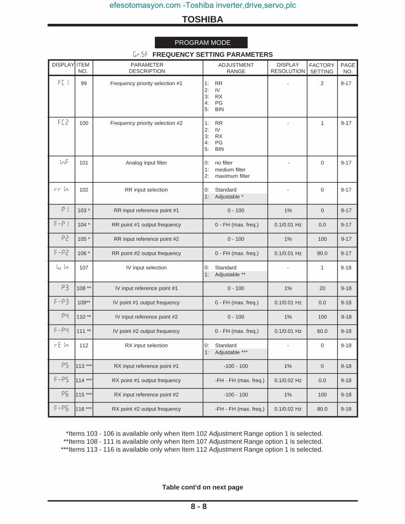
TOSHIBA
ITEMNO.
DISPLAY DISPLAYRESOLUTION
FACTORYSETTING
8 - 8
PAGENO.
PARAMETERDESCRIPTION
ADJUSTMENTRANGE
Table cont'd on next page
fc1 99 Frequency priority selection #1 1: RR - 2 9-172: IV3: RX4: PG5: BIN
fc2 100 Frequency priority selection #2 1: RR - 1 9-172: IV3: RX4: PG5: BIN
1nf 101 Analog input filter 0: no filter - 0 9-171: medium filter2: maximum filter
rr1n 102 RR input selection 0: Standard - 0 9-171: Adjustable *
p1 103 * RR input reference point #1 0 - 100 1% 0 9-17
f-p1 104 * RR point #1 output frequency 0 - FH (max. freq.) 0.1/0.01 Hz 0.0 9-17
p2 105 * RR input reference point #2 0 - 100 1% 100 9-17
f-p2 106 * RR point #2 output frequency 0 - FH (max. freq.) 0.1/0.01 Hz 80.0 9-17
1u1n 107 IV input selection 0: Standard - 1 9-181: Adjustable **
p3 108 ** IV input reference point #1 0 - 100 1% 20 9-18
f-p3 109** IV point #1 output frequency 0 - FH (max. freq.) 0.1/0.01 Hz 0.0 9-18
p4 110 ** IV input reference point #2 0 - 100 1% 100 9-18
f-p4 111 ** IV point #2 output frequency 0 - FH (max. freq.) 0.1/0.01 Hz 60.0 9-18
re1n 112 RX input selection 0: Standard - 0 9-181: Adjustable ***
p5 113 *** RX input reference point #1 -100 - 100 1% 0 9-18
f-p5 114 *** RX point #1 output frequency -FH - FH (max. freq.) 0.1/0.02 Hz 0.0 9-18
p6 115 *** RX input reference point #2 -100 - 100 1% 100 9-18
f-p6 116 *** RX point #2 output frequency -FH - FH (max. freq.) 0.1/0.02 Hz 80.0 9-18
*Items 103 - 106 is available only when Item 102 Adjustment Range option 1 is selected.**Items 108 - 111 is available only when Item 107 Adjustment Range option 1 is selected.
***Items 113 - 116 is available only when Item 112 Adjustment Range option 1 is selected.
gr.sf FREQUENCY SETTING PARAMETERS
PROGRAM MODE
efesotomasyon.com -Toshiba inverter,drive,servo,plc

TOSHIBA
ITEMNO.
DISPLAY DISPLAYRESOLUTION
FACTORYSETTING
8 - 9
PAGENO.
PARAMETERDESCRIPTION
ADJUSTMENTRANGE
*Items 118 - 121 are available only when Item 117 Adjustment Range option 1 is selected.**Items 123 - 126 are available only when Item 122 Adjustment Range option 1 is selected.
***Item 128 is available only when Item 127 Adjustment Range is set to other than "0"
Table cont'd on next page
gr.sf FREQUENCY SETTING PARAMETERS (cont'd)
PROGRAM MODE
pg1n 117 PG input selection 0: Standard - 0 9-181: Adjustable*
p7 118* PG input reference point #1 -100 - 100 1% 0 9-18
f-p7 119* PG point #1 output frequency -FH - FH (max. freq.) 0.1/0.02 Hz 0.0 9-18
p8 120* PG input reference point #2 -100 - 100 1% 100 9-18
f-p8 121* PG point #2 output frequency -FH - FH (max. freq.) 0.1/0.02 Hz 80.0 9-18
b11n 122 BIN input selection 0: Standard - 0 9-18
1: Adjustable**
p9 123** BIN input reference point #1 0 - 100 % 1% 0 9-18
f-p9 124** BIN point #1 output frequency -FH - FH (max. freq.) 0.1/0.02 Hz 0.0 9-18
pa 125** BIN input reference point #2 0 - 100 % 1% 100 9-18
f-pa 126** BIN point #2 output frequency -FH - FH (max. freq.) 0.1/0.02 Hz 80.0 9-18
jOg 127 Jog run frequency 0.0 - 20*** 0.1/0.01 Hz 0.0 9-18
J5tP 128*** Jog stop control 0: Decelerated stop - 0 9-181: Coast to stop2: DC injection braking
Insp
ectio
n &
Prec
autio
nsO
pera
ting
Spec
ifica
tions
Wiri
ngEq
uipm
ent
Term
inal
Con
nect
ions
Ope
ratio
nPa
ram
eter
Spec
ifica
tions
Para
met
erEx
plan
atio
nsO
pera
tion
Exam
ples
Serv
ice
&Tr
oubl
esho
otD
imen
sion
s &
Wei
ghts
Inde
xR
efer
ence
Pane
lM
odes
Ope
ratin
g
efesotomasyon.com -Toshiba inverter,drive,servo,plc

TOSHIBA
sr.n 129 Preset speed selection 0: Disabled - 0 9-181: 1st speed *2: 2nd speed *3: 3rd speed *4: 4th speed *5: 5th speed *6: 6th speed *7: 7th speed *8: 8th speed *9: 9th speed *10: 10th speed *11: 11th speed *12: 12th speed *13: 13th speed *14: 14th speed *15: 15th speed *
sr.m 130 * Mode selection 0: Deactivated - 0 9-181: Activated
FSor 131 * 1st speed (firespeed) Lower limit frequency to 0.1/0.01 Hz 60.0 9-18upper limit frequency
srm1 132 * 1st speed (firespeed) run mode 0: Acc/dec #1, V/F #1, - 0 9-19Note: Reverse run not available in forward run
firespeed run only 1: Acc/dec #1, V/F #1,reverse run **
2: Acc/dec #2, V/F #1,forward run
3: Acc/dec #2, V/F #1,reverse run **
4: Acc/dec #1, V/F #2,forward run
5: Acc/dec #1, V/F #2,reverse run **
6: Acc/dec #2, V/F #2,forward run
7: Acc/dec #2, V/F #2,reverse run **
sr02 133 * 2nd speed Lower limit frequency to 0.1/0.01 Hz 30.0 9-18upper limit frequency
srm2 134 * 2nd speed run mode Same options as - 0 9-19Item 132
sr03 135 * 3rd speed Lower limit frequency to 0.1/0.01 Hz 0.0 9-18upper limit frequency
srm3 136 * 3rd speed run mode Same options as - 0 9-19Item 132
sr04 137 * 4th speed Lower limit frequency to 0.1/0.01 Hz 0.0 9-18upper limit frequency
srm4 138 * 4th speed run mode Same options as - 0 9-19Item 132
ITEMNO.
DISPLAY DISPLAYRESOLUTION
FACTORYSETTING
8 - 10
PAGENO.
PARAMETERDESCRIPTION
ADJUSTMENTRANGE
*Items 130 - 138 are available only when Item 129 Adjustment Range options 1 - 15 is selected.
gr.sf FREQUENCY SETTING PARAMETERS (cont'd)
PROGRAM MODE
** Reverse run not available in 1st speed (firespeed) run mode only.
Table cont'd on next page
efesotomasyon.com -Toshiba inverter,drive,servo,plc

TOSHIBA
sr05 139 * 5th speed Lower limit frequency to 0.1/0.01 Hz 0.0 9-18upper limit frequency
srm5 140 * 5th speed run mode Same options as - 0 9-19Item 132
sr06 141 * 6th speed Lower limit frequency to 0.1/0.01 Hz 0.0 9-18upper limit frequency
srm6 142 * 6th speed run mode Same options as - 0 9-19Item 132
sr07 143 * 7th speed Lower limit frequency to 0.1/0.01 Hz 0.0 9-18upper limit frequency
srm7 144 * 7th speed run mode Same options as - 0 9-19Item 132
sr08 145 * 8th speed Lower limit frequency to 0.1/0.01 Hz 0.0 9-18upper limit frequency
srm8 146 * 8th speed run mode Same options as - 0 9-19Item 132
sr09 147 * 9th speed Lower limit frequency to 0.1/0.01 Hz 0.0 9-18upper limit frequency
srm9 148 * 9th speed run mode Same options as - 0 9-19Item 132
sr10 149 * 10th speed Lower limit frequency to 0.1/0.01 Hz 0.0 9-18upper limit frequency
srma 150 * 10th speed run mode Same options as - 0 9-19Item 132
sr11 151 * 11th speed Lower limit frequency to 0.1/0.01 Hz 0.0 9-18upper limit frequency
srmb 152 * 11th speed run mode Same options as - 0 9-19Item 132
sr12 153 * 12th speed Lower limit frequency to 0.1/0.01 Hz 0.0 9-18upper limit frequency
srmc 154 * 12th speed run mode Same options as - 0 9-19Item 132
sr13 155 * 13th speed Lower limit frequency to 0.1/0.01 Hz 0.0 9-18upper limit frequency
srmd 156 * 13th speed run mode Same options as - 0 9-19Item 132
ITEMNO.
DISPLAY DISPLAYRESOLUTION
FACTORYSETTING
PAGENO.
PARAMETERDESCRIPTION
ADJUSTMENTRANGE
*Items 139 - 156 are available only when Item 129 Adjustment Range options 1 - 15 is selected.
Table cont'd on next page
8 - 11
gr.sf FREQUENCY SETTING PARAMETERS (cont'd)
PROGRAM MODE
Insp
ectio
n &
Prec
autio
nsO
pera
ting
Spec
ifica
tions
Wiri
ngEq
uipm
ent
Term
inal
Con
nect
ions
Ope
ratio
nPa
ram
eter
Spec
ifica
tions
Para
met
erEx
plan
atio
nsO
pera
tion
Exam
ples
Serv
ice
&Tr
oubl
esho
otD
imen
sion
s &
Wei
ghts
Inde
xR
efer
ence
Pane
lM
odes
Ope
ratin
g
efesotomasyon.com -Toshiba inverter,drive,servo,plc

TOSHIBA
sr14 157 * 14th speed Lower limit frequency to 0.1/0.01 Hz 0.0 9-18upper limit frequency
srme 158 * 14th speed run mode Same options as - 0 9-19Item 132
sr15 159 * 15th speed Lower limit frequency to 0.1/0.01 Hz 0.0 9-18upper limit frequency
srmf 160 * 15th speed run mode Same options as - 0 9-19Item 132
ITEMNO.
DISPLAY DISPLAYRESOLUTION
FACTORYSETTING
8 - 12
PAGENO.
PARAMETERDESCRIPTION
ADJUSTMENTRANGE
*Items 157 - 160 are available only when Item 129 Adjustment Range options 1 - 15 is selected.
gr.sf FREQUENCY SETTING PARAMETERS (cont'd)
PROGRAM MODE
efesotomasyon.com -Toshiba inverter,drive,servo,plc

TOSHIBA
pb 161 Dynamic braking (DBR) selection 0: No DBR - 0 9-201: With DBR, no OLr
detection2: With DBR, and OLr
detection *
pbr 162 * DBR resistor value 1.0 - 1000 0.1 Ohm ***** 9-20
pbcp 163 * DBR capacity 0.01 - 600 0.01 kW ***** 9-20
Op55 164 Overvoltage stall protection 0: On - 0 9-201: Off
dbf 165 DC injection braking start frequency 0 - 120 ** 0.1/0.01 Hz 0.0 9-21
dbc 166 ** DC injection current 0 - 100%/A 1 %/A 0 9-21
dbt 167 ** DC injection time 0 - 10 0.1 sec 0.0 9-21
dbsl 168 Fwd/Rev DC injection priority control 0: Off - 0 9-211: On
db1n 169 Motor shaft stationary control 0: Off - 0 9-211: On
estp 170 Emergency stop selection 0: Coast to stop - 0 9-211: Decelerated stop2: DC injection stop ***
edbt 171*** Emergency stop DC injection time 0 - 10 0.1 sec 0.1 9-21
rtry 172 Number of retry attemps selection 0: No retry - 5 9-211: Retry 1 time ****2: Retry 2 times ****3: Retry 3 times ****4: Retry 4 times ****5: Retry 5 times ****6: Retry 6 times ****7: Retry 7 times ****8: Retry 8 times ****9: Retry 9 times ****10: Retry 10 times ****
rtt 173 **** Retry time setting 0.0 - 10 0.1 sec 3.0 9-21
ITEMNO.
DISPLAY DISPLAYRESOLUTION
FACTORYSETTING
8 - 13
PAGENO.
PARAMETERDESCRIPTION
ADJUSTMENTRANGE
Table cont'd on next page
*Items 162 - 163 are available only when Item 161 Adjustment Range option 2 is selected.**Items 166 - 167 are available only when Item 165 Adjustment Range is set to other than "0".
***Item 171 is available only when Item 170 Adjustment Range option 2 is selected.****Item 173 is available only when Item 172 Adjustment Range options 1 - 10 are selected.
*****Default wattage and ohm values depend on the drive size.
gr.pr PROTECTION PARAMETERS
PROGRAM MODE
Insp
ectio
n &
Prec
autio
nsO
pera
ting
Spec
ifica
tions
Wiri
ngEq
uipm
ent
Term
inal
Con
nect
ions
Ope
ratio
nPa
ram
eter
Spec
ifica
tions
Para
met
erEx
plan
atio
nsO
pera
tion
Exam
ples
Serv
ice
&Tr
oubl
esho
otD
imen
sion
s &
Wei
ghts
Inde
xR
efer
ence
Pane
lM
odes
Ope
ratin
g
efesotomasyon.com -Toshiba inverter,drive,servo,plc

TOSHIBA
Uuc 174 Regeneration power ride-through control 0: Off - 0 9-211: On *
Uuct 175 * Regeneration power ride-through time 0.0 - 25 0.1 sec 2.0 9-22
arst 176 Auto-restart (motor speed search) 0: Off - 3 9-221: On momentary
power failure2: On ST make/break
(commercial powerswitching)
3: Both 1 and 2
tHr1 177 Electronic thermal protection level #1 10 - 100%/A 1%/A 100 9-22
Olf 178 Overload reduction start-up frequency 0 - 30 0.1/0.01 Hz 30.0 9-22
Olt 179 Motor 110% overload time limit 10 - 2400 10 sec 600 9-22
Olm 180 Overload selection 0: Standard - 1 9-221: Soft stall On2: OLMt trip Off3: Soft stall On,
OLMt trip Off
stc1 181 Stall protection #1 0: On ** - 0 9-221: Off
stl1 182 ** Stall protection level (current limit level adjust) 10 - 215%/A 1 %/A 110 9-22
Upsl 183 Undervoltage trip selection 0: Trip disabled - 0 9-231: Trip (during run)
Upt 184 Undervoltage detection time 0 - 10 0.01 sec 0.03 9-23
llp 185 Low current detection selection 0: Trip disabled - 0 9-23(output fault detection) 1: Trip on detection
llpc 186 Low current detection level 0 - 100%/A 1%/A 0 9-23
llpt 187 Low current detection time 0 - 255 1 sec 0 9-23
Ocls 188 Output short-circuit detection selection (OCL) 0: Standard - 0 9-231: Standard, High speed
motor use2: Position use (during
JOG)3: High speed motor
use, Position use(during JOG)
ITEMNO.
DISPLAY DISPLAYRESOLUTION
FACTORYSETTING
8 - 14
PAGENO.
PARAMETERDESCRIPTION
ADJUSTMENTRANGE
*Item 175 is available only when Item 174 Adjustment Range option 1 is selected.**Item 182 is available only when Item 181 Adjustment Range option 0 is selected.
Table cont'd on next page
gr.pr PROTECTION PARAMETERS
PROGRAM MODE
efesotomasyon.com -Toshiba inverter,drive,servo,plc

TOSHIBA
Otsl 189 Overtorque trip selection 0: Trip disabled - 0 9-231: Trip enabled
OTL 190 Overtorque trip level 0 - 200%/A 1%/A 150 9-23
trcl 191 Fault trip saving 0: Fault cleared when - 0 9-23power cycled
1: Fault display retainedwhen power cycled *
fan 192 Cooling fan control selection 0: Automatic - 0 9-231: Always On
Ojt 193 Cumulative run timer alarm setting 0.00 - 999.9 0.02 175.0 9-24(1 = 100 hours) (two hours)
LA15 194 IV analog input loss 0: Regular E3 - 0 9-241: Run at LL after IV loss
if running before loss **2: Run at UL after IV loss
ifrunning before loss **3: Trip ("lOss") after
IV loss**4: Run at PO15 % of freq
at IV loss if runningbefore IV loss ** & ***
p015 195*** Percentage of frequency at IV loss 0 - 100 1 % 100 9-24
td 196** Minimum time to detect IV loss 0.3 - 1.0 0.1sec 0.3 9-24
DISPLAY
8 - 15
PAGENO.
PROGRAM MODE
Insp
ectio
n &
Prec
autio
nsO
pera
ting
Spec
ifica
tions
Wiri
ngEq
uipm
ent
Term
inal
Con
nect
ions
Ope
ratio
nPa
ram
eter
Spec
ifica
tions
Para
met
erEx
plan
atio
nsO
pera
tion
Exam
ples
Serv
ice
&Tr
oubl
esho
otD
imen
sion
s &
Wei
ghts
Inde
xR
efer
ence
Pane
lM
odes
Ope
ratin
g
DISPLAYRESOLUTION
FACTORYSETTING
PARAMETERDESCRIPTION
ADJUSTMENTRANGE
gr.pr PROTECTION PARAMETERS
ITEMNO.
*This parameter disables the retry function (see Items 172 and 173).**Item 196 is available only when Item 194 Adjustment Range options 1 - 4 is selected.
***Item 195 is available only when Item 194 Adjustment Range option 4 is selected.
efesotomasyon.com -Toshiba inverter,drive,servo,plc

TOSHIBA
psel 197 Pattern run selection 0: Off - 0 9-251: On *
ptm 198 * Pattern run mode 0: Run pattern is resetwhen inverter is - 0 9-25stopped
1: Pattern switches oncontinuation after astop when currentpattern completes
pt10 199 * 1st Pattern Group 0: Skip - 1 9-25speed #0 selection 1: Preset speed fsor
2: Preset speed Sr023: Preset speed Sr034: Preset speed Sr045: Preset speed Sr056: Preset speed Sr067: Preset speed Sr078: Preset speed Sr089: Preset speed Sr0910: Preset speed Sr1011: Preset speed Sr1112: Preset speed Sr1213: Preset speed Sr1314: Preset speed Sr1415: Preset speed Sr15
pt11 200 * 1st Pattern Group Same options as - 2 9-25speed #1 selection Item 199
pt12 201 * 1st Pattern Group Same options as - 3 9-25speed #2 selection Item 199
pt13 202 * 1st Pattern Group Same options as - 4 9-25speed #3 selection Item 199
pt14 203 * 1st Pattern Group Same options as - 5 9-25speed #4 selection Item 199
pt15 204 * 1st Pattern Group Same options as - 6 9-25speed #5 selection Item 199
pt16 205 * 1st Pattern Group Same options as - 7 9-25speed #6 selection Item 199
pt17 206 * 1st Pattern Group Same options as - 8 9-26speed #7 selection Item 199
ITEMNO.
DISPLAY DISPLAYRESOLUTION
FACTORYSETTING
8 - 16
PAGENO.
PARAMETERDESCRIPTION
ADJUSTMENTRANGE
Table Cont'd on Next Page
gr.pT PATTERN RUN PARAMETERS
PROGRAM MODE
*Items 198 - 206 are available only when Item 197 Adjustment Range option 1 is selected.
efesotomasyon.com -Toshiba inverter,drive,servo,plc

TOSHIBA
ptl1 207 * 1st Pattern Group 1 - 254, 255=infinity - 1 9-26
number of cycles
pt20 206 * 2nd Pattern Group Same options as - 9 9-25speed #0 selection Item 199
pt21 209 * 2nd Pattern Group Same options as - 10 9-25speed #1 selection Item 199
pt22 210 * 2nd Pattern Group Same options as - 11 9-25speed #2 selection IItem 199
pt23 211 * 2nd Pattern Group Same options as - 12 9-25speed #3 selection Item 199
pt24 212 * 2nd Pattern Group Same options as - 13 9-25speed #4 selection Item 199
pt25 213 * 2nd Pattern Group Same options as - 14 9-25speed #5 selection Item 199
pt26 214 * 2nd Pattern Group Same options as - 15 9-25speed #6 selection Item 199
pt27 215 * 2nd Pattern Group Same options as - 0 9-26speed #7 selection Item 199
ptl2 216 * 2nd Pattern Group 1 - 254, 255=infinity - 1 9-26number of cycles
pt30 217 * 3rd Pattern Group Same options as - 1 9-25speed #0 selection Item 199
pt31 218 * 3rd Pattern Group Same options as - 2 9-25speed #1 selection Item 199
pt32 219 * 3rd Pattern Group Same options as - 3 9-25speed #2 selection Item 199
pt33 220 * 3rd Pattern Group Same options as - 4 9-25speed #3 selection Item 199
ITEMNO.
DISPLAY DISPLAYRESOLUTION
FACTORYSETTING
8 - 17
PAGENO.
PARAMETERDESCRIPTION
ADJUSTMENTRANGE
*Items 207 - 220 are available only when Item 197 Adjustment Range option 1 is selected.
Table Cont'd on Next Page
gr.pT PATTERN RUN PARAMETERS (cont'd)
PROGRAM MODE
Insp
ectio
n &
Prec
autio
nsO
pera
ting
Spec
ifica
tions
Wiri
ngEq
uipm
ent
Term
inal
Con
nect
ions
Ope
ratio
nPa
ram
eter
Spec
ifica
tions
Para
met
erEx
plan
atio
nsO
pera
tion
Exam
ples
Serv
ice
&Tr
oubl
esho
otD
imen
sion
s &
Wei
ghts
Inde
xR
efer
ence
Pane
lM
odes
Ope
ratin
g
efesotomasyon.com -Toshiba inverter,drive,servo,plc

TOSHIBA
ITEMNO.
DISPLAY DISPLAYRESOLUTION
FACTORYSETTING
8 - 18
PAGENO.
PARAMETERDESCRIPTION
ADJUSTMENTRANGE
*Items 221 - 234 are available only when Item 197 Adjustment Range option 1 is selected.
Table Cont'd on Next Page
gr.pT PATTERN RUN PARAMETERS (cont'd)
PROGRAM MODE
pt34 221* 3rd Pattern Group Same options as - 5 9-25speed #4 selection Item 199
pt35 222 * 3rd Pattern Group Same options as - 6 9-25speed #5 selection Item 199
pt36 223 * 3rd Pattern Group Same options as - 7 9-25speed #6 selection Item 199
pt37 224 * 3rd Pattern Group Same options as - 8 9-26speed #7 selection Item 199
ptl3 225 * 3rd Pattern Group 1 - 254, 255=infinity - 1 9-26number of cycles
pt40 226 * 4th Pattern Group Same options as - 9 9-25speed #0 selection Item 199
pt41 227 * 4th Pattern Group Same options as - 10 9-25speed #1 selection Item 199
pt42 228 * 4th Pattern Group Same options as - 11 9-25speed #2 selection Item 199
pt43 229 * 4th Pattern Group Same options as - 12 9-25speed #3 selection Item 199
pt44 230 * 4th Pattern Group Same options as - 13 9-25speed #4 selection Item 199
pt45 231 * 4th Pattern Group Same options as - 14 9-25speed #5 selection Item 199
pt46 232 * 4th Pattern Group Same options as - 15 9-25speed #6 selection Item 199
pt47 233 * 4th Pattern Group Same options as - 0 9-26speed #7 selection Item 199
ptl4 234 * 4th Pattern Group 1 - 254, 255=infinity - 1 9-26number of cycles
efesotomasyon.com -Toshiba inverter,drive,servo,plc

TOSHIBA
slm1 235 Speed #1 drive continuation mode 0: Count in secs. from - 0 9-26time of activation *
1: Count in mins. fromtime of activation *
2: Count in secs. fromtime set speed isreached *
3: Count in mins. fromtime set speed isreached *
4: Non-stop (continueuntil STOP command)
5: Continue until nextstep command
slt1 236 * Speed #1 drive time 0 - 8000 1 sec./min. 0 9-26
slm2 237 Speed #2 drive continuation mode Same options as - 0 9-26Item 235
slt2 238 ** Speed #2 drive time 0 - 8000 1 sec./min. 0 9-26
slm3 239 Speed #3 drive continuation mode Same options as - 0 9-26Item 235
slt3 240 *** Speed #3 drive time 0 - 8000 1 sec./min. 0 9-26
slm4 241 Speed #4 drive continuation mode Same options as - 0 9-26Item 235
slt4 242 **** Speed #4 drive time 0 - 8000 1 sec./min. 0 9-26
slm5 243 Speed #5 drive continuation mode Same options as - 0 9-26Item 235
slt5 244 ***** Speed #5 drive time 0 - 8000 1 sec./min. 0 9-26
DISPLAYRESOLUTION
FACTORYSETTING
8 - 19
PAGENO.
PARAMETERDESCRIPTION
ADJUSTMENTRANGE
Table Cont'd on Next Page
*Item 236 is available only when Item 235 Adjustment Range option 0 - 3 is selected.**Item 238 is available only when Item 237 Adjustment Range option 0 - 3 is selected.
***Item 240 is available only when Item 239 Adjustment Range option 0 - 3 is selected.****Item 242 is available only when Item 241 Adjustment Range option 0 - 3 is selected.
*****Item 244 is available only when Item 243 Adjustment Range option 0 - 3 is selected.
DISPLAY ITEMNO.
gr.pT PATTERN RUN PARAMETERS (cont'd)
PROGRAM MODE
Insp
ectio
n &
Prec
autio
nsO
pera
ting
Spec
ifica
tions
Wiri
ngEq
uipm
ent
Term
inal
Con
nect
ions
Ope
ratio
nPa
ram
eter
Spec
ifica
tions
Para
met
erEx
plan
atio
nsO
pera
tion
Exam
ples
Serv
ice
&Tr
oubl
esho
otD
imen
sion
s &
Wei
ghts
Inde
xR
efer
ence
Pane
lM
odes
Ope
ratin
g
efesotomasyon.com -Toshiba inverter,drive,servo,plc

TOSHIBA
slm6 245 Speed #6 drive continuation mode Same options as - 0 9-26Item 235
slt6 246 * Speed #6 drive time 0 - 8000 1 sec./min. 0 9-26
slm7 247 Speed #7 drive continuation mode Same options as - 0 9-26Item 235
slt7 248 ** Speed #7 drive time 0 - 8000 1 sec./min. 0 9-26
slm8 249 Speed #8 drive continuation mode Same options as - 0 9-26Item 235
slt8 250 *** Speed #8 drive time 0 - 8000 1 sec./min. 0 9-26
slm9 251 Speed #9 drive continuation mode Same options as - 0 9-26Item 235
slt9 252 **** Speed #9 drive time 0 - 8000 1 sec./min. 0 9-26
slma 253 Speed #10 drive continuation mode Same options as - 0 9-26Item 235
slta 254 ***** Speed #10 drive time 0 - 8000 1 sec./min. 0 9-26
ITEMNO.
DISPLAYRESOLUTION
FACTORYSETTING
8 - 20
PAGENO.
PARAMETERDESCRIPTION
ADJUSTMENTRANGE
*Item 246 is available only when Item 245 Adjustment Range option 0 - 3 is selected.**Item 248 is available only when Item 247 Adjustment Range option 0 - 3 is selected.
***Item 250 is available only when Item 249 Adjustment Range option 0 - 3 is selected.****Item 252 is available only when Item 251 Adjustment Range option 0 - 3 is selected.
*****Item 254 is available only when Item 253 Adjustment Range option 0 - 3 is selected.
Table Cont'd on Next Page
DISPLAY
gr.pT PATTERN RUN PARAMETERS (cont'd)
PROGRAM MODE
efesotomasyon.com -Toshiba inverter,drive,servo,plc

TOSHIBA
slmb 255 Speed #11 drive continuation mode Same options as - 0 9-26Item 235
sltb 256 * Speed #11 drive time 0 - 8000 1 sec./min. 0 9-26
slmc 257 Speed #12 drive continuation mode Same options as - 0 9-26Item 235
sltc 258 ** Speed #12 drive time 0 - 8000 1 sec./min. 0 9-26
slmd 259 Speed #13 drive continuation mode Same options as - 0 9-26Item 235
sltd 260 *** Speed #13 drive time 0 - 8000 1 sec./min. 0 9-26
slme 261 Speed #14 drive continuation mode Same options as - 0 9-26Item 235
slte 262 **** Speed #14 drive time 0 - 8000 1 sec./min. 0 9-26
slmf 263 Speed #15 drive continuation mode Same options as - 0 9-26Item 235
sltf 264 ***** Speed #15 drive time 0 - 8000 1 sec./min. 0 9-26
ITEMNO.
DISPLAYRESOLUTION
FACTORYSETTING
PAGENO.
PARAMETERDESCRIPTION
ADJUSTMENTRANGE
DISPLAY
8 - 21
gr.pT PATTERN RUN PARAMETERS (cont'd)
PROGRAM MODE
*Item 256 is available only when Item 255 Adjustment Range option 0 - 3 is selected.**Item 258 is available only when Item 257 Adjustment Range option 0 - 3 is selected.
***Item 260 is available only when Item 259 Adjustment Range option 0 - 3 is selected.****Item 262 is available only when Item 261 Adjustment Range option 0 - 3 is selected.
*****Item 264 is available only when Item 263 Adjustment Range option 0 - 3 is selected.
Insp
ectio
n &
Prec
autio
nsO
pera
ting
Spec
ifica
tions
Wiri
ngEq
uipm
ent
Term
inal
Con
nect
ions
Ope
ratio
nPa
ram
eter
Spec
ifica
tions
Para
met
erEx
plan
atio
nsO
pera
tion
Exam
ples
Serv
ice
&Tr
oubl
esho
otD
imen
sion
s &
Wei
ghts
Inde
xR
efer
ence
Pane
lM
odes
Ope
ratin
g
efesotomasyon.com -Toshiba inverter,drive,servo,plc

TOSHIBA
PARAMETERDESCRIPTION
ADJUSTMENTRANGE
fbp1 265 Feedback control selection 0: No feedback control - 0 9-271: PID setpoint control *2: Speed feedback
control *
fb1n 266 * Feedback input signal selection 1: RR input - 2 9-272: IV input3: RX input4: PG feedback
(option board)5: RS232C input6: Communication/12-bit
binary option boardinput
7: BIN input
gp 267 * Proportional gain 0.01 - 2.55 0.01 0.30 9-27
g1 268 * Integral gain 0.01 - 360.0 0.01 sec 2.00 9-27
ga 269 * Differential gain 0.0 - 25.5 0.1 sec 0.0 9-27
gfs 270 * Lag time constant 0 - 255 1 80 9-27
pill 271 * PID lower limit frequency 0 - upper limit 0.01/ 0.1 Hz 10.0 9-27
pul 272 PID deviation limit selection 0: No PID deviation limit - 1 9-271: PID deviation limited**
puUl 273** PID deviation upper limit 0 - 50% 1% 10 9-27
pull 274** PID deviation lower limit 0 - 50% 1% 10 9-27
pg 275 PG input-number of pulses 1 - 9999 1 500 9-27
pgpH 276 PG input-number of phases 1: Single phase input - 2 9-272: Two-phase input
drpc 277 Drooping control 0: Off - 0 9-281: On ***
drpt 278*** Drooping control amount *** 0.0 - 10.0% 0.1% 0.0 9-28
DISPLAY
8 - 22
PAGENO.
Table Cont'd on Next Page
gr.fb FEEDBACK PARAMETERS
PROGRAM MODE
DISPLAYRESOLUTION
FACTORYSETTING
ITEMNO.
*Items 266 - 271 are available only when Item 265 Adjustment Range options 1 - 2 are selected.**Item 273 - 274 are available only when Item 272 Adjustment Range option 1 is selected.
***Item 278 is available only when Item 277 Adjustment Range option 1 is selected.
efesotomasyon.com -Toshiba inverter,drive,servo,plc

TOSHIBA
Ord1 279 Override control 0: Off - 0 9-281: FCRR2: FCIV3: FCRX4: FCPG5: FCPNL6: FCOPT7: FCMLT *
Ord2 280* Override multiplier input selection 0: Reference - 0 9-281: KRR2: KIV3: KRX4: KBIN
Ord3 281* Override change multiplier -100.0 - 100.0% 0.1% 0.0 9-28
ITEMNO.
DISPLAY DISPLAYRESOLUTION
FACTORYSETTING
8 - 23
PAGENO.
PARAMETERDESCRIPTION
ADJUSTMENTRANGE
*Items 280 - 281 are available only when Item 279 Adjustment Range option 7 is selected.
gr.fb FEEDBACK PARAMETERS (cont'd)
PROGRAM MODE
Insp
ectio
n &
Prec
autio
nsO
pera
ting
Spec
ifica
tions
Wiri
ngEq
uipm
ent
Term
inal
Con
nect
ions
Ope
ratio
nPa
ram
eter
Spec
ifica
tions
Para
met
erEx
plan
atio
nsO
pera
tion
Exam
ples
Serv
ice
&Tr
oubl
esho
otD
imen
sion
s &
Wei
ghts
Inde
xR
efer
ence
Pane
lM
odes
Ope
ratin
g
efesotomasyon.com -Toshiba inverter,drive,servo,plc

TOSHIBA
DISPLAY DISPLAYRESOLUTION
FACTORYSETTING
8 - 24
PARAMETERDESCRIPTION
ADJUSTMENTRANGE
gr.tr COMMUNICATION PARAMETERS
PROGRAM MODE
ITEMNO.
*Items 287 - 288 are available only when Item 286 Adjustment Range option 1 is selected.**Item 289 is available only when Item 286 Adjustment Range option 2 is selected.
Table Cont'd on Next Page
Cycle power after changing any parameter in Communication Parameter.
brt2 282 RS232 baud rate 0: 2400 baud - 2 9-291: 4800 baud2: 9600 baud
sm78 283 Number of data bits 0: 7 bits - 0 9-291: 8 bits
sme0 284 Parity 0: Even parity - 0 9-291: Odd parity
1no 285 Inverter number 0 - 255 - 0 9-29
Opt 286 Communication selection 0: Off - 0 9-291: RS485 *2: TOSLINE-F10 **3: TOSLINE-S20 ***4: 12-bit binary input5: 3-digit BCD input
(0.1 Hz units)6: 3-digit BCD input
(1 Hz units)
mst 287 * Master/slave selection 0: Slave - 0 9-291: Master (frequency
command)2: Master (output
frequency)
brt4 288 * RS485 baud rate 0: Normal mode - 0 9-291: High speed mode
m1n 289 ** TOSLINE-F10 0: Off - 0 9-29command input 1: Frequency
command2: Command input3: Frequency
command,command input
PAGENO.
efesotomasyon.com -Toshiba inverter,drive,servo,plc

TOSHIBA
m0Ut 290 ** TOSLINE-F10 0: Off - 0 9-29monitor output 1: Output frequency
2: Status3: Output frequency,
status4: Output current5: Output frequency,
output current6: Status, output
current7: Output frequency,
status, outputcurrent
8: Output voltage9: Output frequency,
output voltage10: Output voltage,
status11: Output frequency,
output voltage,status
12: Output voltage,output current
13: Output voltage,output current,output frequency
14: Output voltage,output current,status
15: Output voltage,output current,output frequency,status
merr 291** TOSLINE-F10 0: Data cleared - 0 9-30communication error mode 1: Data retained
1na 292*** TOSLINE-S20 receive address 0 - 1023 1 0 9-30
OUta 293*** TOSLINE-S20 transmit address 0 - 1023 1 0 9-30
DISPLAY DISPLAYRESOLUTION
FACTORYSETTING
8 - 25
PARAMETERDESCRIPTION
ADJUSTMENTRANGE
ITEMNO.
gr.tr COMMUNICATION PARAMETERS (cont'd)
PROGRAM MODE
**Items 290 - 291 are available only when Item 286 Adjustment Range option 2 is selected.***Items 292 - 293 are available only when Item 286 Adjustment Range option 3 is selected.
PAGENO.
Insp
ectio
n &
Prec
autio
nsO
pera
ting
Spec
ifica
tions
Wiri
ngEq
uipm
ent
Term
inal
Con
nect
ions
Ope
ratio
nPa
ram
eter
Spec
ifica
tions
Para
met
erEx
plan
atio
nsO
pera
tion
Exam
ples
Serv
ice
&Tr
oubl
esho
otD
imen
sion
s &
Wei
ghts
Inde
xR
efer
ence
Pane
lM
odes
Ope
ratin
g
Cycle power after changing any parameter in Communication Parameter.
efesotomasyon.com -Toshiba inverter,drive,servo,plc

TOSHIBA
s1n 294*** TOSLINE-S20 command input 0: Off 0 9-301: Command input2: Base speed value3: Base speed value, command input4: Auxillary base speed value5: Auxillary base speed value, command
input6: Auxillary base speed value, base
speed value7: Auxillary base speed value, base speed
value, command input8: External current limit value9: External current limit value, command
input10: External current limit value, base speed
value11: External current limit value, base speed
value, command input12: External current limit value, auxillary
base speed value13: External current limit value, auxillary
base speed value, command input14: External current limit value, auxillary
base speed value, base speed value15: External current limit value, auxillary
base speed value, base speed value,command input
16: Drooping online gain17: Option 16 + Option 118: Option 16 + Option 219: Option 16 + Option 320: Option 16 + Option 421: Option 16 + Option 522: Option 16 + Option 623: Option 16 + Option 724: Option 16 + Option 825: Option 16 + Option 926: Option 16 + Option 1027: Option 16 + Option 1128: Option 16 + Option 1229: Option 16 + Option 1330: Option 16 + Option 1431: Option 16 + Option 15
DISPLAY
8 - 26
PAGENO.
PARAMETERDESCRIPTION
ADJUSTMENTRANGE
FACTORYSETTING
PROGRAM MODE
***Item 294 is available only when Item 286 Adjustment Range option 3 is selected.
Cycle power after changing any parameter in Communication Parameter.
Table Cont'd on Next Page
ITEMNO.
gr.tr COMMUNICATION PARAMETERS (cont'd)
efesotomasyon.com -Toshiba inverter,drive,servo,plc

TOSHIBA
sOUt 295*** TOSLINE-S20 monitor output 0: Off 0 9-301: Status2: Speed feedback value3: Speed feedback value, status4: Output current value5: Output current value, status6: Output current value, speed feedback
value7: Output current value, speed feedback
value, status8: Excitation current value9: Excitation current value, status10: Excitation current value, speed
feedback value11: Excitation current value, speed
feedback value, status12: Excitation current value, output current
value13: Excitation current value, output current
value, status14: Excitation current value, output current
value, speed feedback value15: Excitation current value, output current
value, speed feedback value, status16: Torque current value17: Option 16 + Option 118: Option 16 + Option 219: Option 16 + Option 320: Option 16 + Option 421: Option 16 + Option 522: Option 16 + Option 623: Option 16 + Option 724: Option 16 + Option 825: Option 16 + Option 926: Option 16 + Option 1027: Option 16 + Option 1128: Option 16 + Option 1229: Option 16 + Option 1330: Option 16 + Option 1431: Option 16 + Option 15
ITEMNO.
DISPLAY
8 - 27
PAGENO.
PARAMETERDESCRIPTION
ADJUSTMENTRANGE
FACTORYSETTING
gr.tr COMMUNICATION PARAMETERS (cont'd)
Cycle power after changing any parameter in Communication Parameter.
Table Cont'd on Next Page
***Item 295 is available only when Item 286 Adjustment Range option 3 is selected.
Insp
ectio
n &
Prec
autio
nsO
pera
ting
Spec
ifica
tions
Wiri
ngEq
uipm
ent
Term
inal
Con
nect
ions
Ope
ratio
nPa
ram
eter
Spec
ifica
tions
Para
met
erEx
plan
atio
nsO
pera
tion
Exam
ples
Serv
ice
&Tr
oubl
esho
otD
imen
sion
s &
Wei
ghts
Inde
xR
efer
ence
Pane
lM
odes
Ope
ratin
g
PROGRAM MODE
efesotomasyon.com -Toshiba inverter,drive,servo,plc

TOSHIBA
f1n5 296 * TOSLINE-S20 reference frequency 0: receive address + 1 - 0 9-30address selection 1: TOSLINE-S20
frequency address **
f1na 297 ** TOSLINE-S20 reference frequency 0 - 1023 1 0 9-30address
serr 298 * TOSLINE-S20 0: data cleared - 0 9-301: data retained
srt 299 * TOSLINE-S20 0: no effect- - 0 9-301: reset S20 option
board
tr1n 300 RS485/12-BIT BINARY % input: 0: Off - 0 9-30bias and gain settings 1: On ***
PL 301 *** Point #1 setting signal 0 - 100% 1% 0% 9-30
F-PL 302 *** Point #1 frequency 0 - max output freq 0.1/0.01 Hz 0Hz 9-30
PH 303 *** Point #2 setting signal 0 - 100% 1% 100% 9-30
F-PH 304 *** Point #2 frequency 0 - max output freq 0.1/0.01 Hz max output 9-30freq
DISPLAY
8 - 28
gr.tr COMMUNICATION PARAMETERS (cont'd)
PARAMETERDESCRIPTION
ADJUSTMENTRANGE
DISPLAYRESOLUTION
FACTORYSETTING
PAGENO.
PROGRAM MODE
*Items 296 - 299 are available only when Item 286 Adjustment Range option 3 is selected.**Item 297 is available only when Item 296 Adjustment Range option 1 is selected.
***Items 301 - 304 are available only when Item 300 Adjustment Range option 1 is selected.
ITEMNO.
efesotomasyon.com -Toshiba inverter,drive,servo,plc

TOSHIBA
8 - 29
INDUSTRIAL APPLICATION PARAMETERS
gr.01 PUMP APPLICATION MACRO
gr.02 FAN APPLICATION MACRO
gr.03 COOLING TOWER APPLICATION MACRO
These groups contain the parameters likely to be used for certain applications. See the E3 ApplicationManual (available from your Toshiba representative) for programming charts and macro values.
Insp
ectio
n &
Prec
autio
nsO
pera
ting
Spec
ifica
tions
Wiri
ngEq
uipm
ent
Term
inal
Con
nect
ions
Ope
ratio
nPa
ram
eter
Spec
ifica
tions
Para
met
erEx
plan
atio
nsO
pera
tion
Exam
ples
Serv
ice
&Tr
oubl
esho
otD
imen
sion
s &
Wei
ghts
Inde
xR
efer
ence
Pane
lM
odes
Ope
ratin
g
efesotomasyon.com -Toshiba inverter,drive,servo,plc

TOSHIBA
fmsl 305 FM terminal function selection 0: Pre-compensation - 0 9-31reference frequency
1: Post-compensationoutput frequency
2: Frequency settingvalue
3: Output current4: DC voltage5: Output voltage6: Torque current7: Excitation current8: PID feedback value9: Motor overload ratio10: Inverter overload ratio11: DBR overload ratio12: Input power13: Output power14: Meter calibration
(100% fixed output)15: Peak output current16: Peak input current
fm 306 Frequency meter adjustment 0 - 65535 - 0.0 9-31
amsl 307 AM terminal function selection 0: Pre-compensation - 3 9-32reference frequency
1: Post-compensationoutput frequency
2: Frequency settingvalue
3: Output current4: DC voltage5: Output voltage6: Torque current7: Excitation current8: PID feedback value9: Motor overload ratio10: Inverter overload ratio11: DBR overload ratio12: Input power13: Output power14: Meter calibration
(100% fixed output)15: Peak output current16: Peak input current
am 308 Ammeter adjustment 0 - 65535 - C 0 9-32
ITEMNO.
DISPLAY DISPLAYRESOLUTION
FACTORYSETTING
8 - 30
PAGENO.
PARAMETERDESCRIPTION
ADJUSTMENTRANGE
PROGRAM MODE
gr.am AM/FM ADJUSTMENT PARAMETERS
efesotomasyon.com -Toshiba inverter,drive,servo,plc

TOSHIBA
apl 309 Industrial application parameters selection 0: Does nothing 0 9-331: Pump application2: Fan application3: Cooling tower application4: Hoist application5: Textiles application6: Machine tool application
typ 310 Standard setting mode selection 0: Does nothing 0 9-331: 50 Hz setting2: 60 Hz setting3: Factory setting4: Trip history clear5: Save user-settings parameters6: Reset to user-settings parameters7: Initialize drive typeform
cMOd 311 Command mode selection 0: Only RS232C input valid 4 9-331: Terminal input valid2: Panel input valid3: Communication option board input valid4: Manual/Auto change over
fMOd 312 Frequency setting mode selection 0: Only RS232C input valid 4 9-331: Terminal input valid2: Panel input valid3: Communication/12-bit binary option
board input valid4: Local/remote change over
pMOd * 313 Panel operation mode selection 0: Prohibit all key operations 63 9-341: Perform reset2: Perform Manual/Auto operations3: Perform reset, perform Manual/Auto
operations4: Perform emergency stop5: Perform emergency stop, perform reset6: Perform emergency stop, perform
Manual/Auto operations7: Perform emergency stop, perform
Manual/Auto operations, perform reset8: Perform run/stop operations9: Perform run/stop operations, perform
reset10: Perform run/stop operations,
perform Manual/Auto operations11: Perform run/stop operations, perform
Manual/Auto operations, perform reset12: Perform run/stop operations,
perform emergency stop13: Perform run/stop operations,
perform emergency stop, perform reset14: Perform run/stop operations, perform
emergency stop, perform Manual/Autooperations
15: Perform run/stop operations, performemergency stop, perform Manual/Autooperations, perform reset
ITEMNO.
DISPLAY
8 - 31
PAGENO.
PARAMETERDESCRIPTION
ADJUSTMENTRANGE
FACTORYSETTING
(Cont'd)
Table Cont'd on Next Page
PROGRAM MODE
gr.Ut UTILITY PARAMETERS
* NOTE: Cycle power after changing ITEM 313, "Panel Operation Mode Selection", ESTOPfrom keypad while in remote mode cannot be disabled.
Insp
ectio
n &
Prec
autio
nsO
pera
ting
Spec
ifica
tions
Wiri
ngEq
uipm
ent
Term
inal
Con
nect
ions
Ope
ratio
nPa
ram
eter
Spec
ifica
tions
Para
met
erEx
plan
atio
nsO
pera
tion
Exam
ples
Serv
ice
&Tr
oubl
esho
otD
imen
sion
s &
Wei
ghts
Inde
xR
efer
ence
Pane
lM
odes
Ope
ratin
g
efesotomasyon.com -Toshiba inverter,drive,servo,plc

TOSHIBA
pMOd *313 Panel operation mode selection 16: Perform parameter read operations 63 9-3417: Option 16 + Option 118: Option 16 + Option 219: Option 16 + Option 320: Option 16 + Option 421: Option 16 + Option 522: Option 16 + Option 623: Option 16 + Option 724: Option 16 + Option 825: Option 16 + Option 926: Option 16 + Option 1027: Option 16 + Option 1128: Option 16 + Option 1229: Option 16 + Option 1330: Option 16 + Option 1431: Option 16 + Option 1532: Perform parameter change operations33: Option 32 + Option 134: Option 32 + Option 235: Option 32 + Option 336: Option 32 + Option 437: Option 32 + Option 538: Option 32 + Option 639: Option 32 + Option 740: Option 32 + Option 841: Option 32 + Option 942: Option 32 + Option 1043: Option 32 + Option 1144: Option 32 + Option 1245: Option 32 + Option 1346: Option 32 + Option 1447: Option 32 + Option 1548: Option 32 + Option 1649: Option 32 + Option 1750: Option 32 + Option 1851: Option 32 + Option 1952: Option 32 + Option 2053: Option 32 + Option 2154: Option 32 + Option 2255: Option 32 + Option 2356: Option 32 + Option 2457: Option 32 + Option 2558: Option 32 + Option 2659: Option 32 + Option 2760: Option 32 + Option 2861: Option 32 + Option 2962: Option 32 + Option 3063: Standard mode (perform all operations)
ITEMNO.
DISPLAY
8 - 32
PAGENO.
PARAMETERDESCRIPTION
ADJUSTMENTRANGE
FACTORYSETTING
(cont'd)
gr.Ut UTILITY PARAMETERS (cont'd)
PROGRAM MODE
Table Cont'd on Next Page
* NOTE: Cycle power after changing ITEM 313, "Panel Operation Mode Selection", ESTOPfrom keypad while in remote mode cannot be disabled.
efesotomasyon.com -Toshiba inverter,drive,servo,plc

TOSHIBA
ITEMNO.
DISPLAY DISPLAYRESOLUTION
FACTORYSETTING
8 - 33
PARAMETERDESCRIPTION
ADJUSTMENTRANGE
PROGRAM MODE
pass 314 Pass number 00 - 99 1 00 9-34
ucpU 315 CPU version Can be monitored only - - 9-34
urOm 316 ROM version Can be monitored only - - 9-34
ueep 317 EEPROM version Can be monitored only - - 9-34
fOrm 318 Drive typeform Can be monitored only - - 9-34
mOn1 319 Status monitor display selections 1: Post-compensation - 2 9-35output frequency
2: Frequency commandsetting
3: Output current4: Input voltage5: Output voltage6: Torque current7: Excitation current8: PID feedback value9: Motor overload ratio10: Drive overload ratio11: DBR overload ratio12: Input power13: Output power14: RR input value15: Peak load current *16: Peak input voltage *17: Kilowatt hours18: Megawatt hours
` mOn2 320 Status monitor display selections Same options as - 3 9-35Item 319
mOn3 321 Status monitor display selections Same options as - 4 9-35Item 319
mOn4 322 Status monitor display selections Same options as - 5 9-35Item 319
dsp2 323 Frequency units multiplication factor ** 0 (Off), 0.01 - 200 0.01 0.00 9-35
dspf 324 Frequency display resolution 0: 1 Hz - 1 9-351: 0.1 Hz2: 0.01 Hz
dspt 325 ACC/DEC time units selection 0: 0.1 secs - 0 9-351: 0.01 secs
dspc 326 Current units selection 0: % - 0 9-351: A
dspu 327 Voltage units selection 0: % - 1 9-351: V
gr.Ut UTILITY PARAMETERS (cont'd)
* The input voltage and output current peak monitor values are reset after each STOP command. However if the drive is stopped for less than 2 seconds, the peak values may not be reset.
** When the the multiplier is anything other than "0", the "Hz" units will not be displayed.
Table cont'd on next page
PAGENO.
Insp
ectio
n &
Prec
autio
nsO
pera
ting
Spec
ifica
tions
Wiri
ngEq
uipm
ent
Term
inal
Con
nect
ions
Ope
ratio
nPa
ram
eter
Spec
ifica
tions
Para
met
erEx
plan
atio
nsO
pera
tion
Exam
ples
Serv
ice
&Tr
oubl
esho
otD
imen
sion
s &
Wei
ghts
Inde
xR
efer
ence
Pane
lM
odes
Ope
ratin
g
efesotomasyon.com -Toshiba inverter,drive,servo,plc

TOSHIBA
ITEMNO.
DISPLAY DISPLAYRESOLUTION
FACTORYSETTING
8 - 34
PAGENO.
PROGRAM MODE
gr.Ut UTILITY PARAMETERS (cont'd)
PARAMETERDESCRIPTION
ADJUSTMENTRANGE
blnd 328 Blind function selection 0: Items 329-345 blinded - 1 9-361: Unblind Items 329-345*
blf2 329 * Fundamental parameters #2 blind 0: Blind this group - 0 9-361: Add this group to visible list
blpn 330 * Panel control parameters blind 0: Blind this group - 0 9-361: Add this group to visible list
blst 331 * Terminal selection parameters blind 0: Blind this group - 1 9-361: Add this group to visible list
blsc 332 * Special control parameters blind 0: Blind this group - 1 9-361: Add this group to visible list
blsf 333 * Frequency setting parameters blind 0: Blind this group - 0 9-361: Add this group to visible list
blpr 334 * Protection parameters 0: Blind this group - 1 9-36
blind 1: Add this group to visible list
blpt 335 * Pattern run control parameters 0: Blind this group - 0 9-36
blind 1: Add this group to visible list
blfb 336 * Feedback control parameters 0: Blind this group - 1 9-36blind 1: Add this group to visible list
bltr 337 * Communication parameters 0: Blind this group - 1 9-36blind 1: Add this group to visible list
bl01 338 * Industrial application parameters 0: Blind this group - 1 9-37 (Pump) blind 1: Add this group to visible list
bl02 339 * Industrial application parameters 0: Blind this group - 1 9-37 (Fan) blind 1: Add this group to visible list
bl03 340 * Industrial application parameters 0: Blind this group - 1 9-37 (Cooling tower) blind 1: Add this group to visible list
blam 344 * AM/FM adjustment parameters 0: Blind this group - 1 9-37blind 1: Add this group to visible list
blmt 345 * Motor parameters 0: Blind this group - 0 9-37blind 1: Add this group to visible list
*Items 329 - 345 are available only when Item 328 Adjustment Range option 1 is selected.
Items 341 - 343 are Non-applicable and do not appear.
(* Group must be unblinded to access group's parameters)
efesotomasyon.com -Toshiba inverter,drive,servo,plc

TOSHIBA
ITEMNO.
DISPLAY DISPLAYRESOLUTION
FACTORYSETTING
8 - 35
PAGENO.
PARAMETERDESCRIPTION
ADJUSTMENTRANGE
mt.p 346 Number of motor poles 2, 4, 6, 8, 10, 12, 14, 16 2 4 9-38
mt.c 347 Motor rated capacity 0.1 - 90.0 kW 0.1kW * 9-38
mt.t 348 Motor type 0: Toshiba EQP-III - 0 9-38motor
1: Toshiba standardmotor
2: Other **
mt.u 349** Rated voltage for 460V inverter 90 - 600 5V 460 9-38Rated voltage for 230V inverter 90 - 600 5V 230
mt.f 350 ** Rated frequency 0 - 400 2 Hz 60 9-38
mt.r 351 ** Rated RPM 0 - 9999 1 RPM 1710 9-38
mt.tn 352 ** Auto-tuning 0: Auto-tuning disabled - 0 9-381: Auto-tuning enabled
mt.1H 353 Load moment of inertia 0: Small - 1 9-381: Medium2: Large3: Very large
gr.mt MOTOR PARAMETERS
PROGRAM MODE
* Items 345 factory setting depends on inverter rating (1 HP = .746kW).** Items 349 - 352 are available only when Item 348 Adjustment Range option 2 is selected.
Insp
ectio
n &
Prec
autio
nsO
pera
ting
Spec
ifica
tions
Wiri
ngEq
uipm
ent
Term
inal
Con
nect
ions
Ope
ratio
nPa
ram
eter
Spec
ifica
tions
Para
met
erEx
plan
atio
nsO
pera
tion
Exam
ples
Serv
ice
&Tr
oubl
esho
otD
imen
sion
s &
Wei
ghts
Inde
xR
efer
ence
Pane
lM
odes
Ope
ratin
g
efesotomasyon.com -Toshiba inverter,drive,servo,plc

TOSHIBA
pt13 354 pt-- if no currently Currently active pattern group number n/a n/a 9-39active pattern group or and pattern speed **pattern speed
n145 355 n--- if no pattern Number of pattern group repetitions n/a n/a 9-39group reptitions remaining remaining **
sr12 356 sr-- if no preset Number of the preset speed being n/a n/a 9-39speed is being used used **
2365 357 ---- if no pattern Remaining pattern time n/a n/a 9-39time remaining * (secs or mins) **
fr-F 358 fr-F or Fr-r Turning direction of motor ------ fr-F 9-39
: 60.0 359 Post compensation output Monitor #1 ------ : c 0 9-39frequency
: 60.0 360 Frequency command setting ------ : c 0 9-39
: c 0 361 Output current ------ : c 0 9-39
: Y 0 362 Input voltage ------ : c 0 9-39
: P 0 363 Output voltage ------ : c 0 9-39
: 0 364 Torque current ------ : c 0 9-39
: E 0 365 Excitation current ------ : c 0 9-39
: d 0 366 PID feedback value ------ : c 0 9-39
: l 0 367 Motor overload ratio ------ : c 0 9-39
: g 0 368 Drive overload ratio ------ : c 0 9-39
: r 0 369 DBR overload ratio ------ : c 0 9-39
: h 0 370 Input power ------ : c 0 9-39
: H 0 371 Output power ------ : c 0 9-40
: j 0 372 RR input value ------ : c 0 9-40
: 0 373 Peak load current ------ : c 0 9-40
: u 0 374 Peak input voltage ------ : c 0 9-40
: U 0 375 Kilowatt hour energy ------ : c 0 9-40
: m 0 376 Megawatt hour energy ------ : c 0 9-40
STANDARD MONITOR MODE
ITEMNO.
DISPLAYRANGE
PARAMETERDESCRIPTION
DISPLAYRESOLUTION
FACTORYSETTING
PAGENO.
b
DISPLAYEDVALUE ***
u
8 - 36
Table Cont'd on Next Page
(depending on M0n1 setting inItem 319, one of the 18 values in
Items 359 to 376 will be displayed)
* This display appears as shown here when "non-stop (continue until STOP command)" or "continueuntil next step command" is selected as the speed's continue mode in the Pattern Run ControlParameters group.
** Parameters are only displayed when in pattern run.*** Displayed values will vary depending on existing drive conditions and monitor settings.
efesotomasyon.com -Toshiba inverter,drive,servo,plc

TOSHIBA
8 - 37
STANDARD MONITOR MODE
PAGENO.
ITEMNO.
DISPLAYRANGE
PARAMETERDESCRIPTION
DISPLAYRESOLUTION
FACTORYSETTING
DISPLAYEDVALUE *
* Displayed values will vary depending on existing drive conditions and monitor settings.** Monitor #2, #3, and #4 functions are identical to monitor #1 but the actual displayed value will
depend on status monitor display adjustment items selected in Utility parameter Items 320,321, or 322 (if different from default value).
*** See drive trip codes page 7-19
Insp
ectio
n &
Prec
autio
nsO
pera
ting
Spec
ifica
tions
Wiri
ngEq
uipm
ent
Term
inal
Con
nect
ions
Ope
ratio
nPa
ram
eter
Spec
ifica
tions
Para
met
erEx
plan
atio
nsO
pera
tion
Exam
ples
Serv
ice
&Tr
oubl
esho
otD
imen
sion
s &
Wei
ghts
Inde
xR
efer
ence
Pane
lM
odes
Ope
ratin
g
Table cont'd from previous Page
: y 0 377 Input voltage Monitor #2 ** ------ : y 0 9-40
: p 0 378 Output voltage Monitor #3 ** ------ : p 0 9-40
: 0 379 Torque current Monitor #4 ** ------ : 0 9-40
: A111111 380 (See code on page 11-8) Input terminal status monitor ------ n/a 9-40
: B111111 381 (See code on page 11-8) Input terminal status monitor ------ n/a 9-40
: 0111111 382 (See code on page 11-8) Output terminal status monitor ------ n/a 9-40
:t 0.00 383 n/a Total run time monitor ------ n/a 9-40
*** 384 n/a Past trip #1 monitor ------ n/a 9-40
*** 385 n/a Past trip #2 monitor ------ n/a 9-40
*** 386 n/a Past trip #3 monitor ------ n/a 9-40
*** 387 n/a Past trip #4 monitor ------ n/a 9-40
b b
efesotomasyon.com -Toshiba inverter,drive,servo,plc

TOSHIBA
9 - 1
Item 1, ACCELERATION TIME #1 (acc1)This parameter sets the time for drive output frequency to go from 0 Hz to MAXIMUM OUTPUTFREQUENCY (FH) (Item 19). A small acceleration time may result in an overcurrent trip.
Item 2, DECELERATION TIME #1 (dec1)This parameter sets the time for drive output frequency to go from MAXIMUM OUTPUTFREQUENCY (FH) (Item 19) to 0 Hz. A small deceleration time may result in an overvoltage trip.
Item 3, UPPER LIMIT FREQUENCY (Ul)This parameter sets the maximum frequency the drive will output, regardless of reference.
Item 4, LOWER LIMIT FREQUENCY (Ll)This parameter sets the lowest speed the drive can run at, regardless of reference. If this parameter isset to a non-zero value and the drive is given a run command (i.e. F-CC closure or RUN button), the drivewill run at (Ll) if the reference is less than (Ll).
Item 5, SWITCH ON FLY (sfly)This parameter allows switching frequency commands between LOCAL and REMOTE modes and toswitch control commands between MANUAL and AUTO modes while drive is running.
Item 6, IV INPUT SELECTION (iv1n)Use this parameter to allow adjustment of the RR reference's bias and gain. Items 7 and 8 define onepoint on a % input reference vs. output Hz graph; Items 9 and 10 define another. The drive varies itsoutput frequency as its input changes according to a line connecting these points. See graph below. Withdefault programming, drive outputs 40 Hz with 5 volts on the "IV" terminal.
Item 7, IV REFERENCE POINT #1 (p3)Use this parameter to set a percentage of reference.
Item 8, IV REF POINT #1 FREQUENCY (f-p3)Use this parameter to set the desired drive output Hz when its reference has the value set in Item 7 above.
Item 9, IV REFERENCE POINT #2 (p4)Use this parameter to set a percentage of reference. The "IV" terminal's range is 0-10 volts, so the factorydefault of 100% corresponds to 10 volts.
Item 10, IV REF POINT #2 FREQUENCY (f-p4)Use this parameter to set the desired output frequency when the reference has the value set in Item 9above.
SETUP MODE PARAMETERS (sttp)
REF POINT #2 FREQREF POINT #1 FREQ
Bias/Gain of Frequency Input
REFERENCE POINT #2: 100%
REFERENCE POINT #1: 0% Output Hz80 Hz0 Hz
Input ReferenceSignal
efesotomasyon.com -Toshiba inverter,drive,servo,plc

TOSHIBA
9 - 2
Item 11, ELECTRONIC THERMAL PROTECT LEVEL #1 (tHr1)Use this parameter to scale the motor overload protection to a specific motor's amp rating. Can be enteredin percent or in amps, depending on the setting of Item 326, CURRENT UNITS SELECTION (dspc). Forpercent setting, divide the motor full load amps by drive full load amps and multiply by 100.
Item 12, STALL PROTECTION ENABLE #1 (stc1)Stall is a drive function used to limit the motor current by reducing output voltage and frequency in an effortto reduce the load. Stall is most effective on variable torque loads. This parameter turns stall off/on.
Item 13, STALL PROTECTION LEVEL #1 (stl1)Enter the current limit in amps or in percent of drive rating. See Item 326, CURRENT UNITSSELECTION (dspc), to change units from % to amps.
Item 14, OVERLOAD SELECTION (OLM)This parameter adjusts the overload protection scheme.
0: Standard1: Soft stall on. Soft stall reduces output frequency only when the drive is in its overload
region. Soft stall helps prevent drive from tripping on "inverter overload" (0l1n) . 2: Motor overload trip off.3: Soft stall on and motor overload trip off.
Motor overload sensing is "on" unless "2" or "3" is selected.
INVERTER OVERLOAD (OL1M) cooling time is approximately one minute after trip.MOTOR OVERLOAD (OLMt) cooling time is approximately five minutes after trip.DBR OVERLOAD (OLr) cooling time is approximately thirty seconds after trip.
Item 15, MOTOR 110% OVERLOAD TIME LIMIT (OLt)This parameter sets the time the drive will output 110% of the current set by Item 11, (tHr1) beforetripping on "motor overload" (0lmt).
Item 16, INDUSTRIAL APPLICATION SELECTION (apl)This parameter can be changed only when the drive's output is 0.0 Hz. When programmed with a non zerovalue, the drive will initialize itself (prior programming is erased) to parameter values that lend themselvesto specific applications.
Item 17, STANDARD SETTING MODE SELECTION (typ)This parameter can be changed at any time. This parameter resets the parameter values of the drive asfollows:
1: Default drive to typical 50 Hz application settings.2: Default drive to typical 60 Hz application settings.3: Default drive to Toshiba factory settings listed in "Factory Setting" column on pages 8-1
through 8-35. Past four faults in the monitor erased.4: Erase past four faults in the monitor.5: Save present parameter settings in separate "user" default memory.6: Default drive to "user" default memory.7: Clear "inverter typeform error" (etyp) (also defaults drive to factory values).
Item 18, PASS NUMBER (pass)Incorrect entry of the setting in this parameter prevents resetting keypad lockout (Item 313 (pm0d) set to"0"). Item 314 (pass) is viewable through RS232 port.
SETUP MODE PARAMETERS (sttp)
Insp
ectio
n &
Prec
autio
nsO
pera
ting
Spec
ifica
tions
Wiri
ngEq
uipm
ent
Term
inal
Con
nect
ions
Ope
ratio
nPa
ram
eter
Spec
ifica
tions
Para
met
erEx
plan
atio
nsO
pera
tion
Exam
ples
Serv
ice
&Tr
oubl
esho
otD
imen
sion
s &
Wei
ghts
Inde
xR
efer
ence
Pane
lM
odes
Ope
ratin
g
efesotomasyon.com -Toshiba inverter,drive,servo,plc

TOSHIBA
9 - 3
Item 19, MAXIMUM OUTPUT FREQUENCY (FH)This parameter cannot be changed while the motor is running. It affects accel/decel times, binaryfrequency references, and other parameters and functions. To limit the drive's output frequencyrange, adjust UPPER LIMIT FREQUENCY (Ul) and/or LOWER LIMIT FREQUENCY (ll) (see Items 24and 25 below).
Item 20, BASE FREQUENCY (vL1)This parameter sets the frequency at which the drive's output voltage reaches its maximum.
Item 21, BASE FREQUENCY VOLTAGE SELECTION (ulSl)The parameter affects the drive's maximum output voltage as follows:
0: The output voltage fluctuates with the input voltage.1: The output voltage is set according to the input voltage when the drive is first powered.2: The output voltage is set by Item 22, MAXIMUM OUTPUT VOLTAGE #1 (ulu1).
Item 22, MAXIMUM OUTPUT VOLTAGE #1 (ulu1)This parameter sets the drive's maximum output voltage (the output voltage cannot exceed the inputvoltage) .
Item 23, REVERSE DISABLE OPERATION SELECTION (D15R)The drive will not run in reverse with this parameter set to option 1.
Item 24, UPPER LIMIT FREQUENCY (Ul)This parameter sets the maximum frequency that the drive will output, regardless of reference.
Item 25, LOWER LIMIT FREQUENCY (ll)This parameter sets the lowest speed the drive can run, regardless of reference. If this parameter is setto a non-zero value and the drive is given a run command (i.e. F-CC closure or RUN button), thedrive will run at LOWER LIMIT FREQUENCY (ll) if the reference is less than LOWER LIMITFREQUENCY (ll).
Item 26, VOLTS PER HERTZ PATTERN (PT)The value in this parameter sets the way the output voltage changes with output frequency:
1: Constant torque: Drive output varies linearly with an output frequency change (at 30 Hz,output voltage is approximately half of what is is at 60 Hz).
2: Variable torque: Drive varies output voltage as the square of output frequency change (at 30Hz, output voltage is approximately 1/4 of what it is at 60 Hz).
3: Automatic torque boost: Drive increases output voltage at low output frequences in orderto increase motor starting torque.
4: Automatic torque boost with energy saving feature: Same as number 3 above, but the outputvoltage is lowered during lightly loaded periods.
5: True torque control: Drive maximizes torque developed by motor and compensates formotor slip. Item 328, BLIND FUNCTION SELECTION (blnd) and Item 345, MOTORPARAMETERS BLIND (blmt), must also be set to option 1 so that GROUP: MOTORRATING PARAMETERS (grmt) can be adjusted (see page 8-35).
6: True torque control with energy saving feature: Same as number 5 above, but the outputvoltage is lowered during lightly loaded periods (reduces idle amps).
Item 27, VOLTAGE BOOST #1 (uB1)This parameter increases output voltage at low frequencies enabling a motors operated in constantor variable torque modes to develop more starting torque. Too much voltage boost could result in anovercurrent trip.
FUNDAMENTAL PARAMETERS #1( gr.f)
efesotomasyon.com -Toshiba inverter,drive,servo,plc

TOSHIBA
9 - 4
Item 28, ACCELERATION TIME #1 (acc1)AT#1 sets the time for drive output frequency to go from 0 Hz to MAXIMUM OUTPUT FREQUENCY (FH)(Item 19). A small acceleration time may result in an overcurrent trip.
Item 29, DECELERATION TIME #1 (dec1)This parameter sets the time for drive output frequency to go from MAXIMUM OUTPUT FREQUENCY (FH)(Item 19) to 0 Hz. A small deceleration time may result in an overvoltage trip.
Item 30, ACC/DEC PATTERN #1 (scu1)This value determines the way the drive's output frequency varies with time during an accel or decel asfollows:
0: Linear pattern - Drive's output frequency change is linear with respect to time. For example, if the output goes from 0 to 30 Hz in 5 seconds, it will take 10 seconds to go from 0 to 60 Hz.
1: Self-adjusting - Drive changes value in acc1 and dec1 based on current during accel and bus voltage during decel to prevent overcurrent/overvoltage trips. Every time a run/stop is executed, the drive changes existing data in acc1 and dec1 (RAM). Drive may require a few run/stop
commands to optimize value. To store modified acc1 and dec1 values, read value in acc1 and dec1 then press READ/WRITE to write values into memory (EEPROM).
2: S pattern - Drive output frequency's rate of change is slow near beginning and end of accel/decel.
MAXIMUM OUTPUT FREQUENCY (FH)
commanded frequency
TIME
OU
TP
UT
HZ
* **
***
acc1
* S pattern accel time contributed by Item 31, ACCEL/DECEL PATTERN ADJUST LOW (scl) ** S pattern accel time contributed by Item 32, ACCEL/DECEL PATTERN ADJUST HIGH (scH) *** Total S pattern accel time Drive follows similar curve during decel.
3: Overspeed pattern - When outputting a frequency greater than the motor's base frequency,drive extends accel/decel time to reduce possibility of overload trip due to reduction in torque.
****
TIME
commanded frequency
OU
TP
UT
HZ
acc1
**** Actual accel time
Item 31, ACCEL/DECEL PATTERN ADJUST LOW (scl)expressed as a percentage of Item 28, this time is represented as "*" in the S Pattern graph for Item 30.
Item 32, ACCEL/DECEL PATTERN ADJUST HIGH (scH)expressed as a percentage of Item 28, this time is represented as "**" in the S Pattern graph for Item 30.
FUNDAMENTAL PARAMETERS #1 ( gr.f)
Insp
ectio
n &
Prec
autio
nsO
pera
ting
Spec
ifica
tions
Wiri
ngEq
uipm
ent
Term
inal
Con
nect
ions
Ope
ratio
nPa
ram
eter
Spec
ifica
tions
Para
met
erEx
plan
atio
nsO
pera
tion
Exam
ples
Serv
ice
&Tr
oubl
esho
otD
imen
sion
s &
Wei
ghts
Inde
xR
efer
ence
Pane
lM
odes
Ope
ratin
g
MAXIMUM OUTPUT FREQUENCY (FH)
BASE FREQUENCY #1 (ul1)
efesotomasyon.com -Toshiba inverter,drive,servo,plc

TOSHIBA
9 - 5
Item 33, BASE FREQUENCY #2 (ul2)See Item 20, BASE FREQUENCY #1 (ul1)
Item 34, MAXIMUM OUTPUT VOLTAGE #2 (ulu2)See Item 22, MAXIMUM OUTPUT VOLTAGE #1 (ulu1)
Item 35, VOLTAGE BOOST #2 (ub2)See Item 27, VOLTAGE BOOST #1 (ub1)
Item 36, ELECTRONIC THERMAL PROTECT LEVEL #2 (tHr2)This parameter lowers the drive's overload to protect the motor. Divide motor full-load amps by drivefull-load amps and multiply by one hundred and enter the result in this parameter. Input in ampswith Item 326, CURRENT UNITS SELECTION (dspc), is set to option 1.
Item 37, STALL PROTECTION ENABLE #2 (stc2)Stall is a drive function wherein the drive limits the motor current by reducing output voltage and frequencyin an effort to reduce load. Stall is most effective on variable torque loads. This parameter turnsstall off/on.
Item 38, STALL PROTECTION LEVEL #2 (sel2)Enter the current limit in amps or in percent of drive rating. See Item 326, CURRENT UNITSSELECTION (dspc), to change units from % to amps.
Item 39, ACCELERATION TIME #2 (acc2)See Item 28, ACCELERATION TIME #1
Item 40, DECELERATION TIME #2 (dec2)See Item 29, DECELERATION TIME #1 (dec1)
Item 41, ACC/DEC PATTERN #2 SELECTION (scu2)See Item 30, ACC/DEC PATTERN #1 SELECTION (scu1)
Item 42, ACC/DEC #1/#2 SWITCHING FREQUENCY (ad2f)The drive can be programmed to switch from accel/decel time #1 to accel/decel time #2 based on outputfrequency. Enter the frequency at which the drive should switch from accel/decel time #1 to accel/deceltime #2.
Note for GROUP:FUNDAMENTAL PARAMETERS #2The parameters in this group are similar to those found in GROUP: FUNDAMENTAL PARAMETERS #1(gr.f). These two groups allow the user to program the drive for operation with two different motors (onlyone motor connected to drive at a time). The user can determine if GROUP: FUNDAMENTALPARAMETERS #1 (gr.f) or if GROUP: FUNDAMENTAL PARAMETERS #2 (gr.f2) is active by settingItem 45, FUNDAMENTAL PARAM SWITCHING (ptp) as desired or by setting one of the drive's inputterminal's function to "12" and opening/closing that terminal to the CC terminal. The user can alsodetermine if ACCELERATION TIME #1 (acc1)/DECELERATION TIME #1 (dec1) or ACCELERATIONTIME #2 (acc2)/DECELERATION TIME #2 (dec2) is active by setting Item 46, ACCEL/DECEL #1/#2SELECTION (ad2) or by setting one of the drive's input terminal's functions to "9" and opening/closingthat terminal to the CC terminal.See page 9-7 for more information on programming the input terminals.
FUNDAMENTAL PARAMETERS #2 ( gr.f2)
efesotomasyon.com -Toshiba inverter,drive,servo,plc

TOSHIBA
9 - 6
Item 43, DIRECTION SELECTION (FORWARD/REVERSE) (fr)This parameter determines direction when commanding start/stop from keypad. Direction can also bechanged from the keypad by pressing READ/WRITE and the up or down arrow simultaneously (with Item43 set to "1").
Item 44, STOP PATTERN SELECTION (stpp)This parameter determines whether the drive follows the decel curve when the STOP button is pressed orif it performs a coast-stop. Coast stop is also performed when ST-CC is broken.
Item 45, FUNDAMENTAL PARAM SWITCHING (ptp)This parameter determines whether GROUP: FUNDAMENTAL PARAMETERS #1 (gr.f) orGROUP: FUNDAMENTAL PARAMETERS #2 (gr.f2) is used.
Item 46, ACC/DEC #1 OR #2 SELECTION (ad2)If the keypad is being used for the RUN/STOP command, then change this parameter to choose whichtimes and pattern are currently utilized. If the drive is getting a run/stop command via the terminal strip (i.e."F"-"CC" made or "R"-"CC" made), the user can remotely choose which accel/decel is used by the driveby programming one of the input terminal's functions (see items 51-61) to a value of "9" and then closingthis terminal to "CC" when acc/dec #2 is to be used. See item 42, ACC/DEC #1/#2 SWITCHFREQUENCY (ad2f) to change which acc/dec time is used based on drive's output frequency.
Item 47, PANEL RESET SELECTION (pre5)Use this parameter to limit the type of fault that can be manually reset from the panel:
0: Overcurrents, overloads, overvoltages, and overheat1: Only overload faults2: Only overload and overcurrent faults
Item 48, PANEL FEEDBACK CONTROL (pfbc)Turns feedback on/off when stop/starting from keypad. Option 0 allows keypad to set setpoint. Option 1turns feedback off, letting keypad act as a regular frequency referrence.
Item 49, SWITCH ON FLY (sfly)See Item 5 page 9-1
FUNDAMENTAL PARAMETERS #2 ( gr.f2)
Insp
ectio
n &
Prec
autio
nsO
pera
ting
Spec
ifica
tions
Wiri
ngEq
uipm
ent
Term
inal
Con
nect
ions
Ope
ratio
nPa
ram
eter
Spec
ifica
tions
Para
met
erEx
plan
atio
nsO
pera
tion
Exam
ples
Serv
ice
&Tr
oubl
esho
otD
imen
sion
s &
Wei
ghts
Inde
xR
efer
ence
Pane
lM
odes
Ope
ratin
g
efesotomasyon.com -Toshiba inverter,drive,servo,plc

TOSHIBA
9 - 7
Item 50 INPUT TERMINAL SELECTION (it)With this parameter set to "0", the drive's input terminals, when shorted to "CC", have the default functionsnoted in Items 51 - 62. The user has the option of changing the function assigned to any of the inputterminals by programming a "1" into item 50 and programming the parameters in Items 51 - 62 asnecessary.
Item 51, "R" INPUT TERMINAL FUNCTION (it0)Sets the function realized when the "R" terminal is shorted to "CC". Default setting is a reverse runcommand. See page 9-11 for codes for other available functions.
Item 52, "S1" INPUT TERMINAL FUNCTION (it1)Sets the function realized when the "S1" terminal is shorted to "CC". Default setting is firespeed control.See page 9-11 for codes for other available functions.
Item 53, "S2" INPUT TERMINAL FUNCTION (it2)Sets the function realized when the "S2" terminal is shorted to "CC". Default setting is feedback control.See page 9-11 for codes for other available functions.
Item 54, "S3" INPUT TERMINAL FUNCTION (it3)Sets the function realized when the "S3" terminal is shorted to "CC". Default setting gives a preset speedreference. See page 9-11 for codes for other available functions.
Item 55, "S4" INPUT TERMINAL FUNCTION (it4)Different with respect to all of the other input terminals; sets the function realized when the "S4" terminalis open to "CC". When S4 is open to "CC", it is the emergency off command and motor will not run.Default setting is emergency off. See page 9-11 for codes for other available functions.
Item 56, "F" INPUT TERMINAL FUNCTION (it5)Sets the function realized when the "F" terminal is shorted to "CC". Default setting gives a forward runcommand. See page 9-11 for codes for other available functions.
Item 57, "RES" INPUT TERMINAL FUNCTION (it6)sets the function realized when the "RES" terminal is shorted to "CC". Default setting resets a fault.See page 9-11 for codes for other available functions.
Item 58, "ST" INPUT TERMINAL FUNCTION (it7)sets the function realized when the "ST" terminal is shorted to "CC". Default setting enables the drive.See page 9-11 for codes for other available functions.
Item 59, "S5" INPUT TERMINAL FUNCTION (it8)sets the function realized when the "S5" terminal is shorted to "CC". Default setting gives a binary speedreference bit. The "S5" terminal is available on the option boards INV3-COM-B and INV3-COM-D.See page 9-11 for codes for other available functions.
Item 60, "S6" INPUT TERMINAL FUNCTION (it9)sets the function realized when the "S6" terminal is shorted to "CC". Default setting is ACC1/DEC1 orACC2/DEC2 selection. The "S6" terminal is available on the option boards INV3-COM-B andINV3-COM-D. See page 9-11 for codes for other available functions.
Item 61, "S7" INPUT TERMINAL FUNCTION (it10)sets the function realized when the "S7" terminal is shorted to "CC". Default setting is emergency off.The "S7" terminal is available on the option boards INV3-COM-B and INV3-COM-D. See page 9-11 forcodes for other available functions.
TERMINAL SELECTION PARAMETERS ( gr.st)
efesotomasyon.com -Toshiba inverter,drive,servo,plc

TOSHIBA
9 - 8
Item 62, POTENTIAL TERMINAL FUNCTION (it11)The potential terminal is an imaginary terminal that the drive considers always shorted to "CC".Any function code from page 9-9 entered here will always be active. For example, if a value of "10" isprogrammed here, the drive will always ESTOP
Notes on input terminals' functions:
1. If the same function is assigned to more than one input terminal, 'OR' logic is in effect.2. If none of the input terminals' function is set to "7" (enable), the drive will assume the drive enabled (just like ST-CC is made).
Item 63, R,S1-S7 INPUT TERMINAL RESPONSE TIME (itf)Use this function to adjust the time between an input terminal's connection to "CC" and the functionrealization. A setting of "100" results in a delay of about 200 milliseconds.
Item 64, "F" INPUT TERMINAL RESPONSE TIME SELECTION (itsf)Use this function to adjust the time between an input terminal's connection to "CC" and the functionrealization. A setting of "100" results in a delay of about 200 milliseconds.
Item 65, "RES" INPUT TERMINAL RESPONSE TIME SELECTION (it6f)Use this function to adjust the time between an input terminal's connection to "CC" and the functionrealization. A setting of "100" results in a delay of about 200 milliseconds.
Item 66, "ST" INPUT TERMINAL RESPONSE TIME SELECTION (it7f)Use this function to adjust the time between an input terminal's connection to "CC" and the functionrealization. A setting of "100" results in a delay of about 200 milliseconds.
Item 67, "RCH" OUTPUT TERMINAL FUNCTION SELECTION (0t0)Enter the code from the table on pages 9-11 and 9-12 to determine when drive will change the state ofthe open collector transistor output.
Item 68, "RCH" OUTPUT TERMINAL DELAY TIME (0t0d)Sets the delay time from sensing a desired condition to the change in state of the "RCH" open collectortransistor output indicating that the condition occurred. Maximum adjustment of "100" is approximately 200milliseconds.
Item 69, "RCH" OUTPUT TERMINAL HOLD TIME (0t0H)Example: Suppose the drive is programmed to sense when it is outputting more than 30 Hz. When theoutput frequency goes above 30 Hz, the open collector transistor will close and the RCH terminal willbecome a ground. Adjusting this parameter to "100" would keep the RCH terminal floating open for anadditional 200 milliseconds after the drive outputted more than 30 Hz.
Item 70, "LOW" OUTPUT CONTACTS FUNCTION SELECTION (0t1)See item 67 above (except dry relay contacts).
Item 71, "LOW" OUTPUT CONTACTS DELAY TIME (0t1d)See item 68 above (except dry relay contacts).
Item 72, "LOW" OUTPUT CONTACTS HOLD TIME (0t1H)See item 69 above (except dry relay contacts).
TERMINAL SELECTION PARAMETERS ( gr.st)
Insp
ectio
n &
Prec
autio
nsO
pera
ting
Spec
ifica
tions
Wiri
ngEq
uipm
ent
Term
inal
Con
nect
ions
Ope
ratio
nPa
ram
eter
Spec
ifica
tions
Para
met
erEx
plan
atio
nsO
pera
tion
Exam
ples
Serv
ice
&Tr
oubl
esho
otD
imen
sion
s &
Wei
ghts
Inde
xR
efer
ence
Pane
lM
odes
Ope
ratin
g
efesotomasyon.com -Toshiba inverter,drive,servo,plc

TOSHIBA
9 - 9
Item 73, "FL" OUTPUT TERMINAL FUNCTION SELECTION (0T2)See Item 70 on page 9-8. On the terminal strip of the 230 and 460 volt models, the normally closedcontact is between "FLA" and "FLC" and the normally open contact is between "FLB" and "FLC".On the terminal strip of the 600 volt models, the normally closed contact is between "FLB" and "FLC" andthe normally open contact is between "FLA" and "FLC".
Item 74, "FL" OUTPUT TERMINAL DELAY TIME (OT2D)See Item 71 on page 9-8.
Item 75, "FL" OUTPUT TERMINAL HOLD TIME (0T2H)See Item 72 on page 9-8.
Item 76, "OUT" OUTPUT TERMINAL FUNCTION SELECTION (OT3)See Item 70 on page 9-8. Available on INV3-COM-B and INV3-COM-D option boards.
Item 77, "OUT" OUTPUT TERMINAL DELAY TIME (OT3D)See Item 71 on page 9-8.
Item 78, "OUT" OUTPUT TERMINAL HOLD TIME (0T3H)See Item 72 on page 9-8.
Item 79, LOW SPEED SIGNAL OUTPUT FREQUENCY (lf)Use this parameter to set the frequency above which one of the outputs changes state.See Items 67, 70, and 73.
Item 80, ACC/DEC COMPLETE DETECT BAND (brch)If one of the open collector output functions is set to "6" (accel/decel complete), use this parameter tooutput the function when the output frequency is within this bandwidth (minus durring accel, plus duringdecel) of the frequency command.
Item 81, SPEED REACH MAXIMUM FREQUENCY (Hrch)Use this parameter to set the output frequency at which one of the outputs changes state during anaccceleration. See Items 67, 70, and 73.
Item 82, SPEED REACH MINIMUM FREQUENCY (lrch)Use this parameter to set the output frequency at which one of the outputs changes state during adeceleration. See Items 67, 70, and 73.
Item 83, COMMERCIAL POWER/INVERTER SWITCHING OUTPUT (CCHG)This parameter determines the effect of cycling power on a faulted drive:
1: Motor runs on bypass when drive trips.2: Motor runs on bypass when a signal is given.3: Both of the above.
Contact your local Toshiba distributor for information on how to program and wire the drive forthis function.
Item 84, COMMERCIAL POWER/INVERTER SWITCHING FREQUENCY (FCHG)On appropriately equipped drives, use this parameter to determine the drive output frequency reachedbefor the bypass circuitry is activated.Contact your local Toshiba distributor for information programming and connecting the drive toutilize this function.
Item 85, "FP" OUTPUT TERMINAL PULSE FREQUENCY (OTFP)Use this parameter to set the number of pulses per output frequency at the open collector of this outputfunction.
TERMINAL SELECTION PARAMETERS ( gr.st)
efesotomasyon.com -Toshiba inverter,drive,servo,plc

TOSHIBA
9 - 10
Item 86, RR INPUT SPECIAL FUNCTION SELECT (inrr)Use this parameter to change the function of the 0-10 volt signal applied to the "RR" terminal:
0: Standard (speed reference)1: Scale MAXIMUM OUTPUT FREQUENCY (fH) ; Minimum 30 Hz2: Adjust multiplier on accel/decel times. Zero volts sets the multiplier to 1, 10 volts sets the multplier to 10.3: Adjust voltage boost. Zero volts sets voltage boost to 0%. 10 volts set the voltage boost to its programmed value.4: Current limit. Ten volts sets current limit to 150%. Contact your Toshiba distributor for information on how to Torque Current limit.
Suggestion: set one of the monitors (Items 319 - 322) to a value of "14" (RR input value) to seeeffective MAXIMUM OUTPUT FREQUENCY (fH), accel/decel multiplier, effective voltage boost,or effective STALL PROTECTION CURRENT LEVEL (sel1 or sel2).
TERMINAL SELECTION PARAMETERS ( gr.st)
Insp
ectio
n &
Prec
autio
nsO
pera
ting
Spec
ifica
tions
Wiri
ngEq
uipm
ent
Term
inal
Con
nect
ions
Ope
ratio
nPa
ram
eter
Spec
ifica
tions
Para
met
erEx
plan
atio
nsO
pera
tion
Exam
ples
Serv
ice
&Tr
oubl
esho
otD
imen
sion
s &
Wei
ghts
Inde
xR
efer
ence
Pane
lM
odes
Ope
ratin
g
efesotomasyon.com -Toshiba inverter,drive,servo,plc

TOSHIBA
9 - 11
The following are the functions that are realized when the appropriate terminal is shorted to "CC" exceptS4, which should be open to "CC". Program the desired code from the list below into Items 51 - 66.Contact the factory on how to make a function active when the terminal is disconnectedfrom "CC" (fail-safe).
Code Function0 Reverse direction command (default for "R" terminal function)1 Binary coding for number of preset speed desired. Value: +12 Binary coding for number of preset speed desired. Value: +23 Binary coding for number of preset speed desired. Value: +4 (default for "S3" terminal function)4 Binary coding for number of preset speed desired. Value: +85 Forward direction command (default for "F" terminal function)6 Reset faults (momentary falling-edge trigger) (default for "RES" terminal function)7 Drive enable (default for "ST" terminal function)8 Jog (also need direction command). See items 128 and 129.9 Select ACC1/DEC1 (open) or ACC2/DEC2 (closed to "CC")10 Emergency stop. Also see Item 170, EMERGENCY STOP SELECTION (estp).11 DC injection. When outputting a frequency under DC INJECTION START FREQUENCY (dbf),
short terminal to "CC" to inject. See Items 165, 166, and 167. Works in remote mode only.12 Activate GROUP:FUNDAMENTAL PARAMETERS #1 (gr.f )(open) or GROUP:FUNDAMENTAL
PARAMETERS #2 (gr.f2) (closed to "CC")13 PID off (closed to "CC") or on (open)14 Select Pattern Run #115 Select Pattern Run #216 Select Pattern Run #317 Select Pattern Run #418 Pattern Run continue signal19 Pattern Run step signal20 Jog forward (includes forward command). See items 127 and 128.21 Jog reverse (includes reverse command). See items 127 and 128.22 Bit #0 for binary speed reference (value of MAXIMUM OUTPUT FREQUENCY(fH)/2048)23 Bit #1 for binary speed reference (value of MAXIMUM OUTPUT FREQUENCY(fH)/1024)24 Bit #2 for binary speed reference (value of MAXIMUM OUTPUT FREQUENCY(fH)/512)25 Bit #3 for binary speed reference (value of MAXIMUM OUTPUT FREQUENCY(fH)/256)26 Bit #4 for binary speed reference (value of MAXIMUM OUTPUT FREQUENCY(fH)/128)27 Bit #5 for binary speed reference (value of MAXIMUM OUTPUT FREQUENCY(fH)/64)28 Bit #6 for binary speed reference (value of MAXIMUM OUTPUT FREQUENCY(fH)/32)29 Bit #7 for binary speed reference (value of MAXIMUM OUTPUT FREQUENCY(fH)/16)30 Bit #8 for binary speed reference (value of MAXIMUM OUTPUT FREQUENCY(fH)/8)31 Bit #9 for binary speed reference (value of MAXIMUM OUTPUT FREQUENCY(fH)/4)32 Bit #10 for binary speed reference (value of MAXIMUM OUTPUT FREQUENCY(fH)/2)33 no function (use terminal to connect wires)34 Motor operated pot: increase frequency reference35 Motor operated pot: decrease frequency reference36 Motor operated pot: clear frequency reference37 Three wire control: NO momentary start push button38 Three wire control: NO momentary stop push button. Contact factory for information on how to
realize stop with a NC contact.39 emulate local/remote mode selection40 Forward (open) or reverse (closed to "CC") command41 Run (use in conjunction with code 40 above)
INPUT TERMINAL FUNCTIONS
Input terminal functions continued on next page
efesotomasyon.com -Toshiba inverter,drive,servo,plc

TOSHIBA
9 - 12
Code Function42 Binary data write (use with 22-32 above). If no input terminal's function is set to "42", the drive
responds immediately to binary references commanded by changing data bits. If one of the inputterminal's function is set to "42", the drive responds to binary reference only when terminal isclosed to "CC". Binary reference is lost when power is cycled.
43 emulate LOCAL/REMOTE key44 emulate MANUAL/AUTO key45 emulate SETUP/PROGRAM/MONITOR key46 emulate UP key47 emulate DOWN key48 emulate READ/WRITE key49 emulate RUN key50 emulate STOP key51 Drive/bypass switching signal52 Reserved for option53 give "RR" priority over "IV" and "RX"54 give "IV" priority over "RR" and "RX"55 damper status input
1: damper open0: damper closes
56 Firespeed ON/OFF
INPUT TERMINAL FUNCTIONS (cont'd)
Insp
ectio
n &
Prec
autio
nsO
pera
ting
Spec
ifica
tions
Wiri
ngEq
uipm
ent
Term
inal
Con
nect
ions
Ope
ratio
nPa
ram
eter
Spec
ifica
tions
Para
met
erEx
plan
atio
nsO
pera
tion
Exam
ples
Serv
ice
&Tr
oubl
esho
otD
imen
sion
s &
Wei
ghts
Inde
xR
efer
ence
Pane
lM
odes
Ope
ratin
g
efesotomasyon.com -Toshiba inverter,drive,servo,plc

TOSHIBA
9 - 13
Value Comments0 Contact will close when drive is at or above Item 7, LOWER LIMIT FREQUENCY (ll)1 Contact will close when drive is not at or above ll (see value 0 above)2 Contacts will close when drive is at Item 6, UPPER LIMIT FREQUENCY (Ul)3 Contacts will close when drive is not at Ul (see value 2 above)4 Default for LOWA/LOWC terminals. Contact will close when drive is at or above speed in Item 79,
LOW SPEED SIGNAL OUTPUT FREQUENCY (lf)5 Contact will close when drive is not at or above lf (see value 4 above)6 Default for RCHA/RCHC terminals. Contact closes when any accel or decel is complete.7 Contact closes when any acceleration or deceleration is not complete (see value 6 above).8 Contact closes when drive is at or above Item 81, SPEED REACH MAXIMUM FREQUENCY (HrcH)
during accel or when drive is at or above Item 82, SPEED REACH MINIMUM FREQUENCY (lrcH)during decel
9 Contact closes when drive is not at or above HrcH during accel or when drive is not at or abovelrcH during decel (see value 8 above).
10 Default for FLA/FLB/FLC terminals. Contact closes when drive is faulted (e0ff is not a fault)11 Contact closes when drive is not faulted.12 Contact closes when drive is faulted on anything except EARTH FAULT (ef1, ef2) or LOAD END
OVERCURRENT (0cl) ("emergency stop" e0ff is not a fault)13 Contact closes when drive is faulted on ef1, ef2 or 0cl (see value 12 above)14 Contact closes when overcurrent stall is active (use as overcurrent pre-alarm). The stall current
level is adjustable via Item 182 (sel1) or Item 38 (sel2).15 Contact closes when overcurrent stall is not active. The stall current level is adjustable via
Item 182 (sel1) or Item 38 (sel2) (see value 14 above).16 Contact closes to signify inverter overload pre-alarm. Example of inverter overload: E3 is rated
for 110% of rated current for 2 minutes. If drive is operated at 110% of rated current for 60 secs,the inverter overload is at 50%, or half of its overload current-time capability. The drivetrips on overload at 100%. Inverter overload pre-alarm starts at 50%.
17 Contact closes to signify drive is not in an overload pre-alarm. See explanation for value 16 above.18 Contact closes to signify motor overload pre-alarm. See explanation for value 16 above.19 Contact closes to signify motor is not in an overload pre-alarm. See explanation for value 16 above.20 Contact closes when heatsink reaches 84O C. Contact opens at 80O C after it has closed21 Contact closes when heatsink is under 84O C. Contact closes at 80O C after it has opened22 Contact closes when drive is displaying "overvoltage" p. See page 11-7.23 Contact closes when drive is not displaying "overvoltage" p. See page 11-7.24 Contact closes when drive is displaying "undervoltage" m0ff. See page 11-7.25 Contact closes when is not displaying "undervoltage" m0ff. See page 11-7.26 Contact closes when output current is at or greater than the current programmed into Item 186,
LOW CURRENT DETECTION LEVEL (llpc) for longer than the time programmed in Item 187,LOW CURRENT DETECTION TIME (llpt)
27 Contact closes when output current is not at or greater than the current programmed into llpc forlonger than the time programmed in llpt (see value 27 above).
28 Contact closes when torque current equals or exceeds the setting programmed into Item 190,OVERTORQUE TRIP LEVEL (0el).
29 Contact closes when torque current does not equal or exceed the setting programmed into0el (see value 28 above).
30 Contact closes when dynamic braking resistor is half way or more into its overload ascalculatedby the drive based upon the setting in Item 162, BRAKING RESISTOR VALUE (pbr) and Item 163,BRAKING RESISTOR POWER RATING (pbcp). See explanation of overload for Value 16.
OUTPUT CONTACTS FUNCTIONS
Output contact functions continued on next page
efesotomasyon.com -Toshiba inverter,drive,servo,plc

TOSHIBA
9 - 14
OUTPUT CONTACTS FUNCTIONS
Value Comments31 Contact closes when dynamic braking resistor is less than half way into its overload as
calculated by the drive based upon the settings in pbr and pbcp (see value 30 on previous page).32 Contact closes when drive is executing an "emergency stop"33 Contact closes when drive is not executing an "emergency stop"34 Contact closes when drive is executing a retry35 Contact closes when the drive is not executing a retry36 Contact closes when drive is running a Pattern Run37 Contact closes when drive is not running a Pattern Run38 Contact closes when the error signal calculated by the drive’s PID equals or exceeds the value
programmed into Item 273, PID DEVIATION UPPER LIMIT (puUl) or Item 274, PIDDEVIATION LOWER LIMIT (pUll).
39 Contact closes when the error signal calculated by the drive’s PID does not equal or exceed thevalue programmed into puUl or pUll (see value 38 above).
40 Contact closes when drive is running at or above 0.01 Hz.41 Contact closes when drive is not running at or above 0.01 Hz.42 Contact closes when drive is faulted on a “severe” fault (not retryable) *43 Contact closes when drive is not faulted on a “severe” fault (not retryable) *44 Contact closes when drive is tripped on a retryable fault *45 Contact closes when drive is not tripped on a retryable fault *46 Auto-bypass control. Contact closes to energize coil of output contactor.47 Opposite logic state (see value 46 above)48 Auto-bypass control. Contact closes to energize coil of bypass contactor.49 Opposite logic state (see value 48 above)50 Contact closes when drive’s cooling fan(s) is on.51 Contact closes when drive’s cooling fan(s) is not on.52 Contact closes when drive is jogging53 Contact closes when drive is not jogging54 Contact closes when drive is getting RUN/STOP command from the keypad55 Contact closes when drive is not getting RUN/STOP command from the keypad56 Contact closes when drive run time is greater than or equal to time programmed into Item 193,
CUMULATIVE RUN TIMER ALARM SETTING (Ojt).57 Contact closes when drive run time is not greater than or equal to time programmed into Ojt
(see value 56 above)58 Contact closes when drive trips on a "communication error" err559 Contact closes when drive does not have a err5 (see value 58 above)60 Contact changes state when drive goes through 0.0 Hz to change direction. Contact is closed/
open during forward/reverse run. Contact maintains current condition at 0.0 Hz when decel iscomplete after a stop command.
61 Contact changes state when drive goes through 0.0 Hz to change direction. Contact is open/closed during forward/reverse run. Contact maintains current condition at 0.0 Hz when decel iscomplete after a stop command.
62 Contact closes when drive has a run command and ST-CC is made63 Contact closes when drive does not have a run command64 Open/Close damper. Contact close: open damper.65 Opposite logic state (see value 64 above)66 IV analog input loss warning. ON: IV lost. Valid when Item 194 (la15) adjustment range option: 0 is
not selected.67 Opposite logic state (see value 66 above)
Insp
ectio
n &
Prec
autio
nsO
pera
ting
Spec
ifica
tions
Wiri
ngEq
uipm
ent
Term
inal
Con
nect
ions
Ope
ratio
nPa
ram
eter
Spec
ifica
tions
Para
met
erEx
plan
atio
nsO
pera
tion
Exam
ples
Serv
ice
&Tr
oubl
esho
otD
imen
sion
s &
Wei
ghts
Inde
xR
efer
ence
Pane
lM
odes
Ope
ratin
g
* Retryable faults include:OVERCURRENT(ACCEL) 0c1, OVERCURRENT(DECEL) 0c2, OVERCURRENT(RUN) 0c3,DC OVERCURENT(ACC) 0c1p, DC OVERCURRENT (DEC) 0c2p, DC OVERCURRENT(RUN) 0c3p,OVERVOLTAGE(ACCEL) 0p1, OVERVOLTAGE(DECEL) 0p2, OVERVOLTAGE(RUN) 0p3, OVERHEAT0H, MOTOR OVERLOAD 0lmt, INVERTER OVERLOAD 0l1n, DBR OVERLOAD TRIP 0lr
efesotomasyon.com -Toshiba inverter,drive,servo,plc

TOSHIBA
9 - 15
SPECIAL CONTROL PARAMETERS ( gr.sc)
Item 91 JUMP FREQUENCY ENABLE (fj.n)This parameters allows the programming of "Jump Frequencies", which are bands of output frequenciesthe drive will not continuously output. The drive allows the user to program up to three separatefrequencies along with a bandwidth for each.
Item 92 JUMP FREQUENCY #1 (fj1)Enter the jump frequency.
Item 93 JUMP FREQUENCY BAND #1 (bfj1)Enter the bandwidth for (fj1). The value entered here will be added to and subtracted from (fj1) todetermine the upper and lower frequencies of the deadband.
Item 94 JUMP FREQUENCY #2 (fj2)See Item 92.
Item 87, START-UP FREQUENCY (f-st)Drive's output frequency remains at 0 Hz until reference commands an output frequency greater than(f-st). When the reference is great enough, drive immediately outputs commanded frequency (no accelramp).
Item 88, END FREQUENCY (f-en)Drive's output frequency immediately goes to 0 Hz (no decel ramp) when reference commands an outputfrequency less than or equal to (f-en).
Item 89, RUN FREQUENCY (frun)Use in conjunction with Item 90, (fHys) below. This parameter is the center of the hysteresis band.
Item 90, RUN FREQUENCY HYSTERESIS (fHys)Use this parameter as a +/- bandwidth around (frun). When the reference signal reaches a value thatcommands a frequency of Frun+Fhys, the drive's output frequency will ramp up to the correspondingfrequency. The output will continue to follow the reference until the frequency it is commanding falls belowFrun-Fhys, at which time the drive will decel to 0 Hz.
Item 89, (frun) and Item 90, (fHys) are not effective when PID control is operating.
HYSTERESIS CHARACTERISTIC
OU
TP
UT
FR
EQ
UE
NC
Y
0 100%FREQUENCY REFERENCE
Start
StopFrun - Fhys
Frun
Frun + Fhys
efesotomasyon.com -Toshiba inverter,drive,servo,plc

TOSHIBA
9 - 16
SPECIAL CONTROL PARAMETERS ( gr.sc)
Insp
ectio
n &
Prec
autio
nsO
pera
ting
Spec
ifica
tions
Wiri
ngEq
uipm
ent
Term
inal
Con
nect
ions
Ope
ratio
nPa
ram
eter
Spec
ifica
tions
Para
met
erEx
plan
atio
nsO
pera
tion
Exam
ples
Serv
ice
&Tr
oubl
esho
otD
imen
sion
s &
Wei
ghts
Inde
xR
efer
ence
Pane
lM
odes
Ope
ratin
g
Item 95 JUMP FREQUENCY BAND #2 (bfj2)See Item 93.
Item 96 JUMP FREQUENCY #3 (fj3)See Item 92.
Item 97 JUMP FREQUENCY BAND #3 (bfj3)See Item 93.
Example of Jump Frequency:Suppose (fj1) is set to 30 Hz and (bfj1) is set to 5 Hz. Suppose a frequency reference startscommanding 0 Hz and slowly increases. The drive's output frequency slowly increases. When thereference hits a level that is commanding 25 Hz (30 - 5 Hz), the drive's output frequency stays at25 Hz even though the reference continues to increase. When the reference hits a level thatcommands 35 Hz (30+5 Hz), the drive accelerates (using the selected acceleration time) from25 Hz to 35 Hz and continues to increase as the reference increases. During a decel, the drive will"stick" at 35 Hz until the reference hits a level that commands 25 Hz, at which time the drivedecelerates (using the selected decel time) from 35 Hz to 25Hz, and resumes following the reference.
Item 98 PWM CARRIER FREQUENCY (cf)This function sets the maximum drive carrier frequency. The function is inversely proportional and asthe output frequency of the drive increases the carrier frequency decreases. For carrier settings above8KHz a derate is required. Derate its current capability (100%<= 8Khz, 90%>=10Khz).For more information consult factory.
CF
15 KHz0 Hz 60 Hz
Car
rier F
requ
ency
Output Frequency
efesotomasyon.com -Toshiba inverter,drive,servo,plc

TOSHIBA
9 - 17
Item 99, FREQUENCY PRIORITY SELECTION #1 (fc1)Use this parameter to give one of the drive's frequency setting signals priority over another. Only whenthe signal set here goes to zero will the drive follow the signal set in Item 81 (Hrch). If the signal selectedhere becomes non-zero, the drive will follow it and ignore the signal selected in Item 81 (Hrch). Set (fc1)to option 5 when using motor operated pot (MOP) control or inputting a binary reference via the drive'sterminal strip. Preset speeds have priority over "RR" and "RX".
Item 100, FREQUENCY PRIORITY SELECTION #2 (fc2)Use this parameter to give one of the drive's frequency setting signals priority over another. Only whenthe signal set in Item 99 (fc1) goes to zero will the drive follow the signal set here. If the signal selectedin (fc1) becomes non-zero, the drive will follow it and ignore the signal selected in (fc2).
Item 101, ANALOG INPUT FILTER (inf)Use this parameter to set the amount of filtering applied to the drive's current/voltage frequency referenceto dampen noise or resonance problems (option 0 is no filtering and option 3 is maximum filtering).
Item 102, RR INPUT SELECTION (rr1n)Use this parameter to allow adjustment of the RR reference's bias and gain. Item 103 (p1) and Item 104(f-p1) define one point on a % input reference vs. output Hz graph; Items 105 (p2) and 106 (f-p2) defineanother. The drive varies the output frequency as the input changes according to a line connecting thesepoints. See graph below.With default programming, drive outputs 40 Hz with 5 volts on the "RR" terminal.
Item 103, RR REFERENCE POINT #1 (p1)Use this parameter to set a percentage of reference.
Item 104, RR REF POINT #1 FREQUENCY (f-p1)Use this parameter to set the desired drive output frequency when its reference has the value setin Item 103 (p2).
Item 105, RR REFERENCE POINT #2 (p2)Use this parameter to set a percentage of reference. The "RR" terminal's range is 0-10 volts, so thefactory default of 100% corresponds to 10 volts.
Item 106, RR REF POINT #2 FREQUENCY (f-p2)Use this parameter to set the desired drive output frequency when its reference has the value setin Item 105 (p2).
FREQUENCY SETTING PARAMETERS (gr.sf)
REF POINT #2 FREQREF POINT #1 FREQ
Bias/Gain of Frequency Input
REFERENCE POINT #2: 100%
REFERENCE POINT #1: 0% Output Hz80 Hz0 Hz
Input ReferenceSignal
efesotomasyon.com -Toshiba inverter,drive,servo,plc

TOSHIBA
9 - 18
Items 107- 111, IV TERMINAL STANDARD OR ADJUSTABLE (1u1n) - (f-p4)Use these parameters to allow adjustment of the "IV" reference's bias and gain. See explanation for Items102 - 106 on preceeding page. With dipswitch in "I" position, drive considers 100% reference = 20 mA(20% would be 4mA). With dipswitch in "V" position, 100% reference = 10 volts. See page 5-2 fordipswitch location.
Items 112 - 116, RX TERMINAL STANDARD OR ADJUSTABLE (re1n) - (f-p6)Use these parameters to allow adjustment of the "RX" reference's bias and gain. See explanation forItems 107 - 111 above. With dipswitch in "5" position, drive considers 100% reference = 5 volts. Withdipswitch in "10" position, 100% reference = 10 volts. See page 5-2 for dipswitch location. Notice that the"RX" reference can be positive or negative, and can represent a positive or negative frequency (directionchange).
Items 117 - 121, PG TERMINAL STANDARD OR ADJUSTABLE (pg1n) - (f-p8)Use these parameters to allow adjustment of the "PG" reference's bias and gain. See explanation forItems 112 - 116 above. PG input is available on option cards INV3-COM-B and INV3-COM-D. Noticethat the PG reference can be positive or negative, and can represent a positive or negative frequency(direction change).
Items 122 - 126, BINARY INPUT STANDARD OR ADJUSTABLE (b11n) - (f-pa)Use these parameters to allow adjustment of a binary reference's bias and gain. See explanation forItems 117 - 121 above. Notice that the binary reference can represent a positive or negative frequency(direction change). These bias/gain adjustments apply to terminals programmed with codes 22-32 onpage 9-11.
Item 127, JOG RUN FREQUENCY (jOg)Use this parameter to set the run frequency during a jog. An accel time of zero is used, so low jogfrequencies of 5 Hz or less and light loads are recommended. For information on jogging from the keypad,see page 7-13. For information on how to jog from the terminal strip, see pages 8-9 and 9-11. During ajog, low speed, speed reach, and PID, functions do not operate.
Item 128, JOG STOP METHOD (jstp)This parameter determines the way a jog is stopped. If DC Injection is selected, also adjust Item 165, DCINJECTION STARTING FREQUENCY (dbf), Item 166, DC INJECTION CURRENT (dbc), and Item 167,DC INJECTION TIME (dbt). Jog is stopped by releasing the "RUN" key (when in panel control), and byopening "F"-"CC" or "R"-"CC" (when in remote control).
Item 129, PRESET SPEED SELECTION (sr.n)Enter the total number of preset speeds to be accessed.
Item 130, PRESET SPEED MODE ACTIVATION (sr.m)If this parameter is set to "1", the corresponding preset speeds' acc/dec time selection, volts per hertzpattern selection, and direction is determined by the setting of (Items 132, 134, 136, etc.)PRESET SPEED#<1,2,3,4,5,6,7,8,9,10 ,11 ,12 ,13 ,14 ,or 15> OPERATING MODE (srm1 - srmf). Directions commandedby closing "F"-"CC" or "R"-"CC" are effectively ignored. If this parameter is set to "0", the direction isdetermined by the terminal strip.
Items 131, 133, 135, 137, 139, 141, 143, 145, 147, 149, 151, 153, 155, 157, 159, PRESET SPEED#<1,2,3,4,5,6,7,8,9,10 ,11 ,12 ,13 ,14 ,or 15> FREQUENCY fsor, sr02 - sr15.Use this parameter to set preset speed frequencies.
FREQUENCY SETTING PARAMETERS (gr.sf)
Insp
ectio
n &
Prec
autio
nsO
pera
ting
Spec
ifica
tions
Wiri
ngEq
uipm
ent
Term
inal
Con
nect
ions
Ope
ratio
nPa
ram
eter
Spec
ifica
tions
Para
met
erEx
plan
atio
nsO
pera
tion
Exam
ples
Serv
ice
&Tr
oubl
esho
otD
imen
sion
s &
Wei
ghts
Inde
xR
efer
ence
Pane
lM
odes
Ope
ratin
g
efesotomasyon.com -Toshiba inverter,drive,servo,plc

TOSHIBA
9 - 19
FREQUENCY SETTING PARAMETERS (gr.sf)
Items 132, 134, 136, 138, 140, 142, 144, 146, 148, 150, 152, 154, 156, 158, 160, PRESET SPEED#<1,2,3,4,5,6,7,8,9,10 ,11 ,12 ,13 ,14 ,or 15> OPERATING MODE (srm1 - srmf)Use this parameter to associate a direction and ACCELERATION TIME #1 (acc1)/DECELERATIONTIME #1 (dec1) or ACCELERATION TIME #2 (acc2)/DECELERATION TIME #2 (dec2) with apreset speed.
When settings S1=1, S2=2, S3=3, S4=4, the "S1", "S2", "S3", and "S4" terminals (seeItems 52 - 55) are preset speed selections via a binary implementation. Some examples:
"S4" to "CC" "S3" to "CC" "S2" to "CC" "S1" to "CC" Commanded Preset Speed #closed open open closed 1closed open closed closed 3open closed open open 12closed closed open closed 5open closed closed closed 15open open open closed 9open open closed open 10
A "F"-"CC" or "R"-"CC" closure is necessary to initiate a preset speed run.
(ITEM 132) 'Firespeed' does not function in reverseCAUTION
efesotomasyon.com -Toshiba inverter,drive,servo,plc

TOSHIBA
9 - 20
PROTECTION PARAMETERS (gr.pr)
Insp
ectio
n &
Prec
autio
nsO
pera
ting
Spec
ifica
tions
Wiri
ngEq
uipm
ent
Term
inal
Con
nect
ions
Ope
ratio
nPa
ram
eter
Spec
ifica
tions
Para
met
erEx
plan
atio
nsO
pera
tion
Exam
ples
Serv
ice
&Tr
oubl
esho
otD
imen
sion
s &
Wei
ghts
Inde
xR
efer
ence
Pane
lM
odes
Ope
ratin
g
Item 161, DYNAMIC BRAKING SELECTION (PB)Adjust this parameter when attaching a dynamic braking resistor to the drive for increased stopping ability.A setting of option 1 affords no protection for the resistor (use for over-sized wattages, or for externally-protected resistors). A setting of option 2 invokes the drive's braking resistor protection (drive will trip on"DBR resistor overload" (0lr) if resistor is overloaded). See Items 162 and 163. For optimum use of thedynamic braking resistor, set Item 164, OVERVOLTAGE STALL PROTECTION (0p55) to option 1, "off".
Item 162, BRAKING RESISTOR VALUE (PBR)Enter ohm value of resistor. See the following tables for recommended DBR sizing.
Item 163, BRAKING RESISTOR POWER RATING (PBCP)Enter kilowatt value of resistor. See the following tables for recommended DBR sizing.
DYNAMIC BRAKING (Feature not available in 460 volt series E3 drives above 20 horsepower)
When a motor is mechanically forced to spin faster than the output frequency of the drive, themotor acts as a generator. This regenerated energy forces current to flow into the drive's DCbus. The bus capacitors will absorb some of the regenerative energy by charging and raising theDC bus voltage. At high bus voltages, the drive can be programmed to fire the IGBT7 dynamicbraking transistor. This prevents a common drive fault, "DC bus overvoltage" (P) . The dynamicbraking resistor, attached by the user to the "PA" and "PB" terminals, dissipates the bus energyas heat when the IGBT7 fires. Two resistor values are of concern: resistance (ohms) and power(watts). Insufficient resistance may lead to IGBT7 damage; too low of a wattage may result inbraking resistor damage from overheating.
50% Braking Resistor 20% Braking Resistor
4055 364 3094080 243 4644110 182 6184160 121 9284220 91 1237
Model Ohms WattsModel Ohms Watts6060 300 15006120 150 30006160 100 45006220 75 60006270 60 75006330 50 90006400 37 120006500 30 150006600 25 180006750 20 22500610K 15 30000612K 12 37500
6060 750 3006120 375 6006160 250 9006220 190 12006270 150 15006330 125 18006400 94 24006500 75 30006600 63 36006750 50 4500610K 38 6000612K 30 7500
Model Ohms Watts2035 101 4642055 61 7732080 40 11592110 31 15462160 21 23192220 16 30922270 13 38652330 13 4638
2400 8 231892500 6 309192600 5 38648
Model Ohms Watts2035 152 1862055 91 3092080 61 4642110 45 6182160 30 9282220 23 12372270 18 15462330 15 18552400 24 46382500 18 61842600 15 7730
4055 121 15464080 81 23194110 61 30924160 40 46384220 30 6184
100% Braking Resistor
100% Braking Resistor 20% Braking Resistor
100% Braking Resistor
20% Braking Resistor
Contact your Toshiba distributor for dynamic braking resistor part numbers and information.
Item 164, OVERVOLTAGE STALL PROTECTION (0pss)This function is turned on as a default setting. Overvoltage stall protection causes the drive toautomatically extend the decel time when the DC bus voltage increases due to regeneration. The valuestored in DECELERATION TIME #1 (dec1)/DECELERATION TIME #2 (dec2) is not changed. Thedrive may still trip on overvoltage if the decel time is too small.
efesotomasyon.com -Toshiba inverter,drive,servo,plc

TOSHIBA
9 - 21
PROTECTION PARAMETERS (gr.pr)
CAUTIONMake sure that workers are not exposed to danger fromequipment suddenly re-starting when a fault occurs anda retry selection option other than "0" has been selected.
Item 174, REGENERATION POWER RIDE THROUGH CONTROL (Uuc)Models 2080-2110 and 4080-4270 take control power from the DC bus; enabling this function allows useof regeneration energy from the motor to maintain control during a brown-out. Accel/decel times may needto be adjusted to avoid overvolltage trips. Always confirm operation.
Item 165, DC INJECTION BRAKING START FREQUENCY (dBf)Use this parameter to set the frequency at which DC injection begins. DC injection can be initiatedremotely by programming one of the input terminals appropriately. See Items 51-61 (it0-it10) andpage 9-7.
Item 166, DC INJECTION CURRENT (dbc)Sets the current level to be employed during DC injection. Current level can be monitored in % of driverating or in amps. Set the current units in Item 326 (dspc).
Item 167, DC INJECTION TIME (dbt)Sets the number of seconds DC is applied to the motor.
Drive will DC inject approximately 60% FLA continuously, 80% for 100 seconds, and 100% for 2seconds without an "inverter overload" (0l1n) trip.
DC injection is active when the drive's output frequency is below DC INJECTION STARTFREQUENCY (dbf) and the drive has a STOP command or a zero reference. DC injection is alsoactive when the drive's output frequency is below Item 32, END FREQUENCY (f-en).
Item 168, FWD/REV DC INJECTION PRIORITY CONTROL (dbsl)When drive is running in forward direction and is given a reverse reference, this parameter determineswhether or not DC injection is active between DC INJECTION STARTING FREQUENCY (dbf) and 0 Hz.Setting option 1 gives DC injection priority over a new run command. With an option setting of 0, a newrun command has priority over DC injection.
Item 169, MOTOR SHAFT STATIONARY CONTROL (dbln)This parameter enables a continuous DC injection into a stopped motor. Amps are set by DC INJECTIONCURRENT (dbc)/ 2. Motor shaft stationary control starts after DC injection and continues until "ST"-"CC" isopened, power is turned off, drive emergency stops, or parameter is changed.
Item 170, EMERGENCY STOP SELECTION (estp)This parameter determines "emergency stop" (e) method.
Item 171, EMERGENCY STOP DC INJECTION TIME (edbt)This is an unique DC injection time for "emergency stops" (e).
Item 172, RETRY SELECTION (rtry)The drive can be programmed to restart after a fault occurs. This parameter sets the number of retryattempts. Auto-restart"motor speed search" (arst) is automatically on during retry. Retry will notfunction if Item 172, FAULT TRIP SAVING (trcl) is set to option 1, "on".
Item 173, TIME BETWEEN RETRY ATTEMPTS (rtt)Adjust this parameter to set the number of seconds between retry attempts.
efesotomasyon.com -Toshiba inverter,drive,servo,plc

TOSHIBA
9 - 22
Item 175, REGENERATION POWER RIDE THROUGH TIME (Uuct)Use this parameter to limit the ride-through time (effective only if there is sufficient regeneration energy).
Item 176, AUTO-RESTART (MOTOR SPEED SEARCH) (arst)This parameter enables the drive's ability to catch a spinning motor:
0: Speed search off1: Drive performs speed search after a power glitch2: Drive performs speed search after "ST"-"CC" is made3: Both 1 and 2 above
A drive with a forward direction command will catch a reversing motor.
Drive and Motor OverloadsThis drive features separate overload curves for itself and the motor. All E3 drives can output 100% oftheir rated current continuously; current levels above 100% are considered overload. The drive overload isfixed: 110% of their rated current for 60 seconds; 150% of their rated current for 0.5 seconds (40 HP orless); 150% of their rated current for 0.3 seconds (50 HP and greater) . The motor's overload curve isdefined by Items 177, 178, 179, and output frequency:
Item 177, ELECTRONIC THERMAL PROTECT LEVEL #1 (tHr1)Use this parameter to scale the motor overload protection to a specific motor's amp rating. Can be enteredin percent or in amps, depending on the setting of Item 326, CURRENT UNITS SELECTION (dspc). Forpercent setting, divide motor full load amps by drive full load amps and multiply by 100.
Item 178, OVERLOAD REDUCTION START FREQUENCY (0lf)The motor overload protection provided by the drive is speed-sensitive by default. With default setting,a drive at 115% of the current set by Item 11, (thr1) will trip on "motor overload" (0lmt) sooner at 15 Hzthan at 60 Hz. Users who have allowed for reduced motor cooling at low speeds can reduce this param-eter to get more overload capability. The drive's overload protection is speed sensitive at frequenciesbelow the value entered here.
Item 179, MOTOR 110% OVERLOAD TIME LIMIT (0lt)This parameter sets the time the drive will output 110% of the current set by Item 11 or Item 177, (tHr1)before tripping on "motor overload" (0lmt).
Item 180, OVERLOAD SELECTION (0lm)This parameter adjusts the overload protection scheme.
0: Standard1: Soft stall on. Soft stall reduces output frequency only when the drive is in its overload region. Soft stall helps prevent drive from tripping on "inverter overload" (0l1m) 2: Motor overload trip off.3: Soft stall on and motor overload trip off.
Motor overload sensing is "on" unless option 2 or 3 is selected."inverter overload" (0l1m) cooling time is approximately one minute after trip"motor overload" (0lmt) cooling time is approximately five minutes after trip"DBR overload" (0lr) cooling time is approximately thirty seconds after trip
Item 181, STALL PROTECTION ENABLE #1 (stc1)Drive current limits when stall protection enable is set to option 0, "on".
Item 182, STALL PROTECTION LEVEL #1 (stl1)Drive will reduce its output frequency and voltage automatically to limit output current to the valueprogrammed here.
PROTECTION PARAMETERS (gr.pr)
Insp
ectio
n &
Prec
autio
nsO
pera
ting
Spec
ifica
tions
Wiri
ngEq
uipm
ent
Term
inal
Con
nect
ions
Ope
ratio
nPa
ram
eter
Spec
ifica
tions
Para
met
erEx
plan
atio
nsO
pera
tion
Exam
ples
Serv
ice
&Tr
oubl
esho
otD
imen
sion
s &
Wei
ghts
Inde
xR
efer
ence
Pane
lM
odes
Ope
ratin
g
efesotomasyon.com -Toshiba inverter,drive,servo,plc

TOSHIBA
9 - 23
Item 183, UNDERVOLTAGE TRIP SELECTION (Upsl)The drive can be programmed to "undervoltage trip" (Up1) when the DC bus voltage is under a factory-setvalue by selecting option 1. See Item 184 also. An undervoltage alarm is available in the form of a driveoutput contact change; see Items 67, 70, or 73 and setting values 24/25 on page 9-13.
Item 184, UNDERVOLTAGE DETECT TIME (Upt)The DC bus must be low for at least this amount before the drive faults on "undervoltage trip" (Up1).
Item 185, LOW CURRENT DETECT SELECTION (llp)The drive can be programmed to "low current trip" (Uc) when its output current is below the valueprogrammed in Item 186 (llpc) for at least the time programmed in Item 187 (llpt). Enter option 1 hereto enable the low current detection. A low current alarm is available in the form of a drive output contactchange; see Items 67, 70, or 73 and setting values 26/27 on page 9-13.
Item 186, LOW CURRENT DETECT LEVEL (llpc)Enter the current amount below which the drive will trip and/or close an appropriately-programmed outputcontact. See Item 326 (dspc) for settings in % or amps.
Item 187, LOW CURRENT DETECTION TIME (llpt)Enter the time the output current must be below the level set in Item 186 (llpc) before the drive tripsand/or closes an appropriately programmed output contact.
Item 188, OUTPUT SHORT-CIRCUIT DETECTION SELECT (0cl5)To protect itself, the drive does an output short-circuit check every time a run is initiated. This parameterchanges the short-circuit check:
0: Standard setting1: When a low impedance motor is used, this setting desensitizes the short-circuit check, reducing nusiance trips.2: This setting programs the drive to perform the check at power up only.3: Combination of 1 and 2 above. Do not operate the drive on a motor with power factor correction capacitors.
Item 189, OVERTORQUE TRIP SELECTION (0tsl)Enter a "1" here to program the drive to fault "overtorque trip" (0t) based on on the torque current amount.See Item 190 (0tl).
Item 190, OVERTORQUE TRIP LEVEL (0tl)Enter the torque current level (depending on the % or amps setting of Item 326 (dspc) for settings in % oramps) where the drive trips and/or closes an appropriately programmed output contact. See Items 67, 70,or 73 and setting values 28/29 on page 9-13.
Item 191, FAULT TRIP SAVING (trcl)This parameter determines the effect of cycling power on a faulted drive:
0: Fault and fault data cleared when drive powers up.1: Drive powers up in tripped state (drive display remains in faulted state, but fault data and fault contact are not maintained).
Setting of Item 173, NUMBER OF RETRY ATTEMPTS (rtry), is ignored by the drive whenthis Item is set to option 1.
Item 192, COOLING FAN CONTROL SELECTION (fan)This parameter determines if the drive's fan is thermostatically controlled or if it runs continuously.
PROTECTION PARAMETERS (gr.pr)
efesotomasyon.com -Toshiba inverter,drive,servo,plc

TOSHIBA
9 - 24
Item 193, CUMULATIVE RUN TIMER ALARM SETTING (0jt)One of the drive's output contacts can be programmed to change state based upon the time entered here.See Items 67, 70, 73 and setting values 56/57 on page 9-14. ".01" is one hour.
Item 194, IV ANALOG INPUT LOSS FUNCTION (la15)This function works when input terminal IV is used for frequency command input. The loss functionrelated parameters are la15, p015, and td. IV loss function is selected by properly setting this function.After it is selected, the drive will work in the following ways:
If la15 is set to 0, it will perform as a normal E3.
If LA15 is not 0, whenever IV signal is lost (defined as when IV signal falls below 10% of full inputscale) for a time defined by td (0.3 second to 1.0 second), a warning signal will be on. Thewarningsignal and IV lost status are cleared by reset. The warning signal can be output to anterminal by setting an output terminal at 66 (or 67 for negative logic). In addition to the warningsignal, the following will be done according to the LA15 setting:
LA15 =1: run at LL speed if the drive is running before IV lost.
LA15 =2: run at UL speed if the drive is running before IV lost.
LA15 =3: drive trip, and display LOSS whether the motor is running or not.
LA15 =4: run at PO15 % of the frequency at the time the IV lost if the drive is running before IV lost.
The other properties are:
The loss of the IV signal can never start the drive automatically. If the motor stops at thetime of IV loss, the motor will stop after IV loss and can not be restarted until reset.
If LL is changed while the IV signal is lost, the drive will follow the lower limit (if LA15 =1).
If the IV signal returns, the drive must be reset to follow the signal; ie, the IV loss statuswill remain until reset.
Loss function works independent of RUN/STOP commands.
Item 195, PERCENTAGE OF FREQUENCY AT IV LOSS (p015)This parameter sets the percentage of frequency where a warning signal will be applied after loss of theIV signal.
Item 196, MINIMUM TIME TO DETECT IV LOSS (td)This parameter sets the minimum amount of time that must pass before the drive reacts to the lossof the IV signal.
PROTECTION PARAMETERS (gr.pr)
Insp
ectio
n &
Prec
autio
nsO
pera
ting
Spec
ifica
tions
Wiri
ngEq
uipm
ent
Term
inal
Con
nect
ions
Ope
ratio
nPa
ram
eter
Spec
ifica
tions
Para
met
erEx
plan
atio
nsO
pera
tion
Exam
ples
Serv
ice
&Tr
oubl
esho
otD
imen
sion
s &
Wei
ghts
Inde
xR
efer
ence
Pane
lM
odes
Ope
ratin
g
efesotomasyon.com -Toshiba inverter,drive,servo,plc

TOSHIBA
9 - 25
PATTERN RUN PARAMETERS (gr.pt)
Pattern RunThe E3 has a feature called pattern run that emulates a low-level PLC. During a pattern run, the drivefollows a pattern group by running at the user's preset speeds for desired amounts of time in desireddirections with desired accel/decel times for a defined number of cycles. The drive has 15 preset speeds,any of which can be assigned to be speeds zero through seven in a pattern group. The drive can hold upto four separate pattern groups, any of which can be remotely selected to run.
Item 197, PATTERN RUN SELECTION (psel)This parameter enables pattern run. When stopping/starting drive from panel, pattern run takes priorityover the keypad's frequency reference.
Item 198, PATTERN RUN CONTINUE MODE (ptm)This parameter determines if a pattern group is continued after a pattern run is stopped and restarted:
0: Pattern group starts over with its first speed1: Pattern resumes at the time of and with the speed at interruption
Items 199, 208, 217, 226, PATTERN GROUP #<1,2,3, or 4 > SPEED #0 (pt10)This parameter determines which preset speed (preset speeds 1 through 15, programmed in odd numberItems 131-159 fsor, sr02 - sr15) is the first speed in the pattern group. Unlike the other speeds #1 - #7,speed #0 is not repeated when PATTERN GROUP #<1,2,3, or 4 > NUMBER OF CYCLES (psel) isgreater than one. Set this parameter to "0" to skip this speed.
Items 200, 209, 218, 227, PATTERN GROUP #<1,2,3, or 4 > SPEED #1 (pt11)This parameter determines which preset speed (preset speeds 1 through 15, programmed in odd numberItems 131-159 fsor, sr02 - sr15) is the next speed in the pattern group. Speed #1 can be but does nothave to be Preset Speed #1.
Items 201, 210, 219, 228, PATTERN GROUP #<1,2,3, or 4 > SPEED #2 (pt12)This parameter determines which preset speed (preset speeds 1 through 15, programmed in odd numberItems 131-159 fsor, sr02 - sr15) is the next speed in the pattern group. Speed #2 can be but does nothave to be Preset Speed #2.
Items 202, 211, 220, 229, PATTERN GROUP #<1,2,3, or 4 > SPEED #3 (pt13)This parameter determines which preset speed (preset speeds 1 through 15, programmed in odd numberItems 131-159 fsor, sr02 - sr15) is the next speed in the pattern group. Speed #3 can be but does nothave to be Preset Speed #3.
Items 203, 212, 221, 230, PATTERN GROUP #<1,2,3, or 4 > SPEED #4 (pt14)This parameter determines which preset speed (preset speeds 1 through 15, programmed in odd numberItems 131-159 fsor, sr02 - sr15) is the next speed in the pattern group. Speed #4 can be but does nothave to be Preset Speed #4.
Items 204, 213, 222, 231, PATTERN GROUP #<1,2,3, or 4 > SPEED #5 (pt15)This parameter determines which preset speed (preset speeds 1 through 15, programmed in odd numberItems 131-159 fsor, sr02 - sr15) is the next speed in the pattern group. Speed #5 can be but does nothave to be Preset Speed #5.
Items 205, 214, 223, 232, PATTERN GROUP #<1,2,3, or 4 > SPEED #6 (pt16)This parameter determines which preset speed (preset speeds 1 through 15, programmed in odd numberItems 131-159 fsor, sr02 - sr15) is the next speed in the pattern group. Speed #6 can be but does nothave to be Preset Speed #6.
efesotomasyon.com -Toshiba inverter,drive,servo,plc

TOSHIBA
9 - 26
PATTERN RUN PARAMETERS (gr.pt)
Items 206, 215, 224, 233, PATTERN GROUP #<1,2,3, or 4 > SPEED #7 (pt17)This parameter determines which preset speed (preset speeds 1 through 15, programmed in odd numberItems 131-159 fsor, sr02 - sr15) is the next speed in the pattern group. Speed #7 can be but does nothave to be Preset Speed #7.
Items 207, 216, 225, 234, PATTERN GROUP #<1,2,3, or 4 > NUMBER OF CYCLES (ptl1)This parameter determines how many times the pattern group made up of speeds #1 through #7 enteredin the above parameters will be repeated.
Items 235, 237, 239, 241, 243, 245, 247, 249, 251, 253, 255, 257, 259, 261, and 263,SPEED #<1,2,3,4,5,6,7,8,9,10 ,11 ,12 ,13 ,14 ,or 15> CONTINUE MODE (slm1 - slmf)This parameter affects the timing of the speeds in a pattern group:
0: Preset speed's time is counted in seconds from the beginning of the run (accel/decel time is included in the time entered in the following parameter, SPEED # <1,2,3,4,5,6,7,8,9,10 ,11 ,12 ,13 ,14 ,or 15> DRIVE TIME (slt1 - sltf)1: Preset speed's time is counted in minutes from the beginning of the run (accel/decel time is included in the time entered in the following parameter, SPEED # <1,2,3,4,5,6,7,8,9,10 ,11 ,12 ,13 ,14 ,or 15> DRIVE TIME (slt1 - sltf)2: Preset speed's time is counted in seconds after preset speed is reached (accel/decel time is not included in the time entered in the following parameter, SPEED # <1,2,3,4,5,6,7,8,9,10 ,11 ,12 ,13 ,14 ,or 15> DRIVE TIME (slt1 - sltf)3: Preset speed's time is counted in minutes after preset speed is reached (accel/decel time is not included in the time entered in the following parameter, SPEED # <1,2,3,4,5,6,7,8,9,10 ,11 ,12 ,13 ,14 ,or 15> DRIVE TIME (slt1 - sltf)4: Non-stop (stop by breaking ST-CC or F-CC or R-CC).5: Drive waits for step command to change speeds. See Items 51 - 62 (1t0 - 1t11) and input terminal functions setting code 19 on page 9-11.
Items 236, 238, 240, 242, 244, 246, 248, 250, 252, 254, 256, 258, 260, 262, and 264, SPEED NUMBER<1,2,3,4,5,6,7,8,9,10,11,12,13,14, or 15> DRIVE TIME (slt1 - sltf)This parameter determines the amount of time associated with each preset speed. The time unit(minutes/seconds is determined by the preceding parameter.
Insp
ectio
n &
Prec
autio
nsO
pera
ting
Spec
ifica
tions
Wiri
ngEq
uipm
ent
Term
inal
Con
nect
ions
Ope
ratio
nPa
ram
eter
Spec
ifica
tions
Para
met
erEx
plan
atio
nsO
pera
tion
Exam
ples
Serv
ice
&Tr
oubl
esho
otD
imen
sion
s &
Wei
ghts
Inde
xR
efer
ence
Pane
lM
odes
Ope
ratin
g
efesotomasyon.com -Toshiba inverter,drive,servo,plc

TOSHIBA
9 - 27
FEEDBACK PARAMETERS ( gr.fb)
Item 265, FEEDBACK CONTROL SELECTION (fbp1)This parameter programs the drive to operate in PID mode (maintain a process variable such aspressure), speed feedback, or in normal mode.
Item 266, FEEDBACK INPUT SIGNAL SELECTION (fb1n)This parameter programs the drive to accept feedback at one of many possible inputs:
1: "RR" terminal2: "IV" terminal3: "RX" terminal4: Pulse generator input (on option board INV3-COM-B or INV3-COM-D)5: RS232 port6: RS485 port or 12 bit input (on option board INV3-COM-A, INV3-COM-C or E3-VF5X-4526A7: Binary input ( via input terminals programmed appropriately - see Items 51 - 62 (1t0 - 1t11) and setting values 22-32 on page 9-11).
Item 267, PROPORTIONAL GAIN (gp)The larger the value here, the quicker the drive responds to changes in feedback. Contact Toshiba for thePID application guideline. READ/WRITE does not have to be pressed to make the value entered effective.
Item 268, INTEGRAL GAIN (g1)Also known as reset, this parameter is actually a time. The smaller the value here, the more pronouncedthe effect of the integral function. Contact Houston for the PID application guideline. READ/WRITE doesnot have to be pressed to make the value entered effective.
Item 269, ANTI-HUNTING GAIN (gA)Also known as differential gain or rate, this parameter is actually a time. The larger the value here, themore pronounced the effect of the differential function. Contact Toshiba for the PID application guideline.READ/WRITE does not have to be pressed to make the value entered effective.
Item 270, LAG TIME CONSTANT (gf5)This parameter effects drive reaction time to a change in feedback. Decrease setting improves response.
Item 271, PID LOWER LIMIT FREQUENCY (pill)When PID is active, Item 4, LOWER LIMIT FREQUENCY (ll )is not effective. This parameter is thelower limit when PID is active.
Item 272, PID DEVIATION LIMIT SELECTION (pul)The amount of correction calculated by the drive can be limited to control possible system oscillations.Select option 1 to limit PID deviation.
Item 273, PID DEVIATION UPPER LIMIT (puUl)The amount of correction calculated by the drive is limited to the value entered here, expressed in termsof percent of Item 19, MAXIMUM OUTPUT FREQUENCY (fH).
Item 274, PID DEVIATION LOWER LIMIT (pull)The amount of correction calculated by the drive is limited to the value entered here, expressed in termsof percent of Item 19, MAXIMUM OUTPUT FREQUENCY (fH).
Item 275, PG INPUT: NUMBER OF PULSES (pg)When an encoder and PG option board (INV3-COM-B or INV3-COM-D) is being used for closed loopspeed control, enter pulses per revolution. When using option board to follow a pulse reference, enternumber of pulses that correspond to a frequency command of one hertz.
Item 276, PG INPUT: NUMBER OF PHASES (pgpH)Use this parameter to select either one or two phase encoder feedback.
efesotomasyon.com -Toshiba inverter,drive,servo,plc

TOSHIBA
9 - 28
Insp
ectio
n &
Prec
autio
nsO
pera
ting
Spec
ifica
tions
Wiri
ngEq
uipm
ent
Term
inal
Con
nect
ions
Ope
ratio
nPa
ram
eter
Spec
ifica
tions
Para
met
erEx
plan
atio
nsO
pera
tion
Exam
ples
Serv
ice
&Tr
oubl
esho
otD
imen
sion
s &
Wei
ghts
Inde
xR
efer
ence
Pane
lM
odes
Ope
ratin
g
FEEDBACK PARAMETERS ( gr.fb)
Item 277, DROOPING CONTROL ENABLE (drpc)Use this parameter to enable the drive's load share function, which continuously stalls based on load.This parameter can be changed while the drive is at a non-zero output frequency, but the change doesnot go into effect until drive is stopped.
Item 278, DROOPING CONTROL AMOUNT (drpt)This parameter sets the maximum amount of droop as a percentage of Item 19 (fH).
When drooping, Output Frequency = Reference Frequency - DroopDroop = MAXIMUM OUTPUT FREQUENCY x DROOPING CONTROL AMOUNT x Torque RatioTorque Ratio (maximum value of 2.0)= operating torque / rated torque
Item 279, OVERRIDE CONTROL SELECTION (0rd1)Use this parameter to create a "trim pot". This allows a user to uniquely adjust the speed of a drive thatis receiving a master reference. The bias/gain of these inputs determines their effect on the masterreference. Select which one of the frequency references will serve as the trim source:
0: none1: "RR" terminal2: "IV" terminal3: "RX" terminal (+/- trim possible)4: Pulse generator input on option card INV3-COM-B or INV3-COM-D (+/- trim possible)5: E3 keypad6: RS485 input or 12-bit input on option cards INV3-COM-A , INV3-COM-C, or G3-VF5X-4526A7: Trim source with multiplier. See Items 280 (0rd2) and 281 (0rd3) below.
Item 280, OVERRIDE MULTIPLIER INPUT SELECTION (0rd2)When used with a multiplier, the following inputs' bias and gain do not determine their effect on the masterreference. Select which of the following trim sources will be used with the muliplier:
0: Frequency reference1: "RR" terminal2: "IV" terminal3: "RX" terminal4: RS485 input or 12-bit input on option cards INV3-COM-A, INV3-COM-C, or G3-VF5X-4526A
Item 281, OVERRIDE CHANGE MULTIPLIER (0rd3)When Item 280 (0rd2) is set to "0", this parameter sets the percent of reference to be added/subtactedto/from the reference. When it is set to option 1, 2, 3, or 4, the value entered here determines themaximum range of trim in terms of percentage of reference. This maximum range of trim includes bothpositive and negative trim bandwidths. Any amount of trim up to this maximum is available by changingthe trim terminal's input. Maximum negative trim is achieved with minimum input on trim terminal.Maximum positive trim is achieved with maximum input on trim terminal.
Example: Suppose Item 280 is set to "1" (RR trim), Item 281 is set to "25%", and a 4-20 mA reference intothe "IV" terminal is commanding 40 Hz. When the "RR" input is 0 volts, the drive outputs 35 Hz (40 - ((40 X0.25)/2)). When the "RR" input is adjusted to 10 volts, the drive outputs 45 Hz (40 + ((40 X 0.25)/2))
Override Data FlowThis figure is useful to
help clarify Items 279, 280,and 281
efesotomasyon.com -Toshiba inverter,drive,servo,plc

TOSHIBA
9 - 29
COMMUNICATION PARAMETERS (gr.tr)
Item 282, RS232 BAUD RATE (brt2)Sets baud rate. Cycle power after changing this parameter.
Item 283, NUMBER OF DATA BITS (sm78)Sets the word length. Cycle power after changing.
Item 284, PARITY SETTING (sme0)Sets the parity. Cycle power after changing this parameter.
Item 285, INVERTER ID NUMBER (ino)Assigns unique ID to drive for use on RS485 net. Cycle power after changing this parameter.
Item 286, COMMUNICATION SELECTION (0pt)Use this parameter to select type of communication:
0: None1: RS485 port on option boards INV3-COM-A, INV3-COM-C, or INV3-COM-B2: Toshiba TOSLINE F10 (twisted pair). Contact your Toshiba distributor for more information3: Toshiba TOSLINE S20 (fiber optic). Contact your Toshiba distributor for more information.4: 12 bit binary reference using option card G3-VF5X-4526A5: Three digit BCD input on card E3-VF5X-4526A ( 0.1 Hz resolution )6: Three digit BCD input on card E3-VF5X-4526A ( 1.0 Hz resolution )
Item 287, MASTER/SLAVE SELECTION (mst)This parameter defines the drive's role in the master/follower scenario. Option 1 entered here will makeslave drives follow the frequency command the master is receiving (master may be stopped while thefollowers run). Option 2 entered here will make the followers run according to the master's outputfrequency.
Item 288, RS485 BAUD RATE (brt4)In conjunction with jumpers J1 ands J2 on the RS485 option board used, this parameter sets the RS485baud rate as follows:
Position of Setting of Item 288 J1 J2 0 1 off off 9600 38400 on off 4800 19200 off on 2400 9600 on on 1200 4800
INV3-COM-A and INV3-COM-B cards' max baud is 19200.INV3-COM-C card's max baud is 38400.
Item 289, TOSLINE F10 COMMAND INPUT (m1n)Determines if drive accepts run/stop and/or frequency commands from TOSLINE. Contact Toshiba PLCmarketing for more information.
Item 290, TOSLINE F10 MONITOR OUTPUT (m0Ut)Determines the drive operating data to be communicated. Contact Toshiba PLC marketing for moreinformation.
Cycle power after changing any communication parameters.
efesotomasyon.com -Toshiba inverter,drive,servo,plc

TOSHIBA
9 - 30
COMMUNICATION PARAMETERS (gr.tr)
Item 291, TOSLINE F10/S20 COMM ERROR MODE (merr)When set to option 0, a zero speed command is commenced if an error occurs. The data prior to the erroris held if option 1 is selected.
Item 292, TOSLINE S20 RECEIVE ADDRESS (1NA)Use this function to set the receive address.
Item 293, TOSLINE S20 TRANSMIT ADDRESS (0UTA)Use this function to set the transmit address.
Item 294, TOSLINE S20 COMMAND INPUT (s1n)Determines if drive accepts run/stop and/or frequency commands from TOSLINE. Contact Toshiba PLCmarketing for more information.
Item 295, TOSLINE S20 MONITOR OUTPUT (s0Ut)Determines the drive operating data to be communicated. Contact Toshiba PLC marketing for moreinformation.
Item 296, TOSLINE S20 REFERENCE FREQUENCY ADDRESS SELECTION (f1n5)Use this function to select for either the reference frequency address or set to receive address + 1.
Item 297, TOSLINE S20 REFERENCE FREQUENCY ADDRESS (fina)Use this function to set the reference frequency address.
Item 298, TOSLINE S20 (5err)Use this function to set up to clear or retain data on the S20 option board.
Item 299, TOSLINE S20 (5rt)Use this function to reset the S20 option board.
Items 300-304 , RS485/12-BIT BINARY BIAS, GAIN (tr1n) - (f-pH)Use these parameters to allow adjustment of the RS485 or 12 bit reference's bias and gain. SeeItems 102-106 for similiar explanation. Slave drive's 100% reference is master's MAXIMUM OUTPUTFREQUENCY (fH), Item 19. RS485 input is available on option cards INV3-COM-A, INV3-COM-B,and INV3-COM-C. 12 bit binary input is available on option card E3-VF5X-4526A.
Cycle power after changing any communication parameters.
Insp
ectio
n &
Prec
autio
nsO
pera
ting
Spec
ifica
tions
Wiri
ngEq
uipm
ent
Term
inal
Con
nect
ions
Ope
ratio
nPa
ram
eter
Spec
ifica
tions
Para
met
erEx
plan
atio
nsO
pera
tion
Exam
ples
Serv
ice
&Tr
oubl
esho
otD
imen
sion
s &
Wei
ghts
Inde
xR
efer
ence
Pane
lM
odes
Ope
ratin
g
efesotomasyon.com -Toshiba inverter,drive,servo,plc

TOSHIBA
9 - 31
AM/FM ADJUSTMENT PARAMETERS ( gr.am)
Item 305, FM TERMINAL FUNCTION SELECTION (FMSL)This parameter determines the drive operating variable associated with the 0-1 mA signal from the "FM"and "CC" terminals. Do not make connections to this terminal with the drive powered. Choices for"FM" terminal's signal's function:
0: (default for "FM"). Pre-compensation reference frequency. This is the drive's internalfrequency command and is affected by acc/dec and PID and droop (same as the actual outputfrequency displayed on the drive's keypad).
1: Post-compensation output frequency may be higher than frequency command (driveoverspeeds to compensate for slip in vector control).
2: Frequency command. Use for master/follower. Not affected by stopping or accel/decel.3: (default for "AM"). Output current. (output amps)2 =(torque amps)2+(excitation amps)2
4: DC bus voltage5: Output voltage6: Torque current. (output current)2 = (torque current)2 + (excitation current)2
7: Excitation current. (output current)2 = (torque current)2 + (excitation current)2
8: PID feedback value. This is the frequency represented by the feedback signal9: Motor overload ratio. Example: Drive is rated for 110% FLA for 1 minutes. If drive runs at
110% for 30 sec, this output will be 50%. Drive trips when ratio hits 100%.10: Inverter overload ratio. See example for selection 9 above.11: Dynamic braking resistor overload ratio. See example for selection 9 above.12: Input power (watts)13: Output power (watts)14: Meter calibration setting15: Peak output current. Peak is reset by cycling power, initiating a run, or resetting drive.16: Peak input voltage. Peak is reset by cycling power, initiating run, or resetting drive.
Calculated from DC bus.
Item 306, FREQUENCY METER ADJUSTMENT (FM)This setting adjusts the gain of the "FM" terminal. With Item 305 (FMSL) option is set to 14, press theup/down arrows (ignoring parameter value shown) until external meter/system reads the following valuefor the chosen operating variable:
For post compensation frequency, adjust until meter/system reads 75% of Item 1, MAXIMUMOUTPUT FREQUENCY (FH)
For post-compensation output frequency, adjust until meter/system reads 75% of Item 1, MAXIMUMOUTPUT FREQUENCY (FH)
For frequency command, adjust until meter/system reads 75% of Item 1, MAXIMUM OUTPUTFREQUENCY (FH)
For output current, adjust until meter/system reads drive rated amps (or 100%)For DC bus voltage, adjust until meter/system 283 VDC for a 230 V drive or 566 VDC for a 460 V
drive.For output voltage, adjust arrows until meter/system reads 200 VAC (or 100%) for a 230 V drive
or 400 VAC (or100%) for a 460 V drive.For torque current, adjust arrows until meter/system reads drive rated amps (or 100%).For excitation current, adjust arrows until meter/system reads drive rated amps (or 100%).For PID feedback value, adjust arrows until meter/system reads 75% of Item 1, MAXIMUM OUTPUT
FREQUENCY (FH)For motor overload ratio, adjust arrows until meter/system reads 100%.For inverter overload ratio, adjust arrows until meter/system reads 100%.For dynamic braking resistor overload ratio, adjust arrows until meter/system reads 100%.For input power, adjust arrows until meter/system reads 346 X drive FLA for a 230 V drive or 692 X
drive FLA for a 460 V drive.
Cont'd on next page
efesotomasyon.com -Toshiba inverter,drive,servo,plc

TOSHIBA
9 - 32
AM/FM ADJUSTMENT PARAMETERS ( gr.am)
Item 306 cont'd, FREQUENCY METER ADJUSTMENT (FM)
For output power, adjust arrows until meter/system reads 346 X drive FLA for a 230 V drive or 692 Xdrive FLA for a 460 V drive.For peak output current, adjust arrows until meter/system reads drive rated amps (or 100%).For peak input voltage, adjust arrows until meter/system reads 200 VAC for a 230 V drive or 400VAC for a 460 V drive.
Item 307, AM TERMINAL FUNCTION SELECTION (amsl)This parameter is programmed like Item 305 (FMsl), but it affects the "AM" terminal.
Item 308, AMMETER ADJUSTMENT (aM)This parameter is programmed like Item 306 (FM), but it affects the "AM" terminal.
Insp
ectio
n &
Prec
autio
nsO
pera
ting
Spec
ifica
tions
Wiri
ngEq
uipm
ent
Term
inal
Con
nect
ions
Ope
ratio
nPa
ram
eter
Spec
ifica
tions
Para
met
erEx
plan
atio
nsO
pera
tion
Exam
ples
Serv
ice
&Tr
oubl
esho
otD
imen
sion
s &
Wei
ghts
Inde
xR
efer
ence
Pane
lM
odes
Ope
ratin
g
efesotomasyon.com -Toshiba inverter,drive,servo,plc

TOSHIBA
9 - 33
UTILITY PARAMETERS (gr.Ut)
Item 309, INDUSTRIAL APPLICATION SELECTION (apl)This parameter can be changed only when the drive's output is 0.0 Hz.When programmed with a non zerovalue, the drive will initialize itself (prior programming is erased) to parameter values that lend themselvesto specific applications. Contact your Toshiba representative for a copy of the Industrial Application Manualwhich lists the specific parameter setting by application macro. When read, this parameter displays twovalues; the one on the left is the previous value, while the one on the right is the current value.
Item 310, STANDARD SETTING MODE SELECTION (typ)This parameter can be changed only when the drive's output is 0.0 Hz. When read, this parameter dis-plays two values; the one on the left is the previous value, while the one on the right is the current value.This parameter resets the parameter values of the drive as follows:
1: Default drive to typical 50 Hz application settings.2: Default drive to typical 60 Hz application settings.3: Default drive to Toshiba factory settings listed in "Factory Setting" column on pages 8-1 through 8-35. Past four faults in the monitor erased.4: Erase past four faults in the monitor.5: Save present parameter settings in separate "user" default memory.6: Default drive to "user" default memory.7: Clear the "Inv typeform error" (etyp) which also defaults drive to factory values.
Item 311, COMMAND MODE SELECTION (CMOD)If sfly = 0, changes to this parameter go into effect only when the drive is at 0.0 Hz. If sfly = 1,changes to this parameter go into effect immediately. This parameter determines where the drive looksfor a stop/start command:
0: RS232 port1: E3 terminal strip only (auto run)2: E3 keypad stop/run buttons only (manual mode)3: RS485 input on option boards INV3-COM-A, INV3-COM-B, or INV3-COM-C4: Manual or auto as determined by setting of MANUAL/AUTO button on keypad
Item 312, FREQUENCY MODE SELECTION (FMOD)If sfly = 0, changes to this parameter go into effect only when the drive is at 0.0 Hz. If sfly = 1,changes to this parameter go into effect immediately. This parameter determines where the drive looksfor a stop/start command:
0: RS232 port1: E3 terminal strip only (remote mode)2: E3 keypad stop/run buttons only (local mode)3: RS485 or 12 bit binary input on option boards INV3-COM-A, INV3-COM-B, INV3-COM-C, or VF5X-4526A4: Local or remote as determined by setting of LOCAL/REMOTE button on keypad
Terminal strip enable, reset, and "emergency stop" commands are always valid, regardless of optionssetting.
Terminal strip enable, reset, and ESTOP commands are always valid, regardless of options setting.With option 2 selected, preset speeds from terminal strip will not function.
efesotomasyon.com -Toshiba inverter,drive,servo,plc

TOSHIBA
Typeform Model Typeform Model Model Typeform
24 E3U2035 47 E3U4110 68 E3U616025 E3U2055 48 E3U4160 69 E3U622026 E3U2080 49 E3U4220 6A E3U627027 E3U2110 4A E3U4270 6B E3U633028 E3U2160 4B E3U4330 6C E3U640029 E3U2220 4C E3U4400 6D E3U65002A E3U2270 4D E3U4500 6E E3U66002B E3U2330 4E E3U4600 6F E3U67502C E3U2400 4F E3U4750 70 E3U610K2D E3U2500 50 E3U410K 71 E3U612K2E E3U2600 51 E3U412K45 E3U4055 65 E3U606046 E3U4080 67 E3U6120
9 - 34
UTILITY PARAMETERS (gr.Ut)
Insp
ectio
n &
Prec
autio
nsO
pera
ting
Spec
ifica
tions
Wiri
ngEq
uipm
ent
Term
inal
Con
nect
ions
Ope
ratio
nPa
ram
eter
Spec
ifica
tions
Para
met
erEx
plan
atio
nsO
pera
tion
Exam
ples
Serv
ice
&Tr
oubl
esho
otD
imen
sion
s &
Wei
ghts
Inde
xR
efer
ence
Pane
lM
odes
Ope
ratin
g
Item 313, PANEL OPERATION MODE SELECTION (pMOD)Cycle power after changing this parameter.This parameter limits what can be done via the keypad. Panel "emergency stop" in remote mode is alwaysvalid. The values entered here that are zero or are a power of two have one function assignedto them:
0: Keypad does nothing except switching between forward/reverse in manual mode1: Reset drive fault only2: Monitor only4: "emergency stop" only8: Run/Stop only16: Read parameters only32: Change parameters only
The rest of the possible parameter values are combinations of the above.Note: to "change parameters only", "read parameters only" should also be selected (See option 48)
TO RESET AFTER OPTION "0" HAS BEEN PROGRAMMED IN ITEM 313 (pMOD):1. Press four keys simultaneously: LOCAL/REMOTE, SPM, R/W, and up arrow2. Drive will return to Item 314 and display : 0
If : 0 doesn't appear after pressing the four keys, cycle power and try again.3. Enter pass number between 00 - 99 with up/down arrows and press READ/WRT. Pass number is
programmed in Item 314 (pass).4. If pass number is entered correctly Item 313 (pMOD) will be reset to option 63, allowing all keypad
operations; if entered incorrectly Err will be displayed.
Item 314, PASS NUMBER (pass)Incorrect entry of the setting in this parameter prevents resettingkeypad lockout (Item 313 (pMOD) set to "0"). Pass number is viewable through RS232 port.
Item 315, CPU VERSION (ucpU)This read-only parameter displays the processor version.
Item 316, ROM VERSION (ur0m)This read-only parameter display the read-only-memeory version.
Item 317, EEPROM VERSION (ueep)This read-only parameter displays the control board EEPROM version.
Item 318, INVERTER TYPEFORM (f0rm)This read-only parameter identifies the drive model number:
efesotomasyon.com -Toshiba inverter,drive,servo,plc

TOSHIBA
9 - 35
UTILITY PARAMETERS (gr.Ut)
Items 319 - 322, STATUS MONITOR #<1,2,3,and 4> SELECT (m0n1) - (m0n4)Pressing MON button displays the drive's monitor mode. See Item 326 (dspc) to display currents in ampsor percent. See Item 327 (dspu) to display voltages in volts or percent. The drive operation variabledisplayed in four of the monitor mode's screens are selectable:
1: Post-compensation output frequency may be higher than frequency command (drive overspeedsto compensate for slip in vector control).
2: Frequency command. Not affected by stopping or accel/decel.Default for STATUS MONITOR #1 DISPLAY SELECT (m0n1)
3: Output current. (output amps)2 =(torque amps)2+(excitation amps)2
Default for STATUS MONITOR #2 DISPLAY SELECT (m0n2)4: Input voltage (calculated from DC bus voltage). If displayed in percent, note that 230 V drives
consider 200 V to be 100% input and 460 V drives consider 400 V to be 100% input.Default for STATUS MONITOR #3 DISPLAY SELECT (m0n3)
5: Output voltage. If displayed in percent, note that 230 V drives consider 200 V to be 100% outputand 460 V drives consider 400 V to be 100% output.Default for STATUS MONITOR #4 DISPLAY SELECT (m0n4)
6: Torque current. (output current)2 = (torque current)2 + (excitation current)2
7: Excitation current. (output current)2 = (torque current)2 + (excitation current)2
8: PID feedback value. This is the frequency represented by the feedback signal9: Motor overload ratio. Example: Drive is rated for 110% FLA for 1 minutes. If drive runs at 110%
for 30 sec, this output will be 50%. Drive trips when ration hits 100%.10: Inverter overload ratio. See example for option 9 above.11: Dynamic braking resistor overload ratio. See example for option 9 above.12: Input power13: Output power14: "RR" terminal input value. The variable displayed here varies with the setting of Item 86,
RR INPUT SPECIAL FUNCTION SELECT (1nrr).15: Peak output current. Peak is reset by cycling power, initiating a run, or resetting drive.16: Peak input voltage. Peak is reset by cycling power, initiating run, or resetting drive.
Calculated from DC bus. If displayed in percent, note that 230 V drives consider 200 V input tobe 100% and that 460 drives consider 400 V input to be 100%.
17: KWH: cumulative kilowatt hour energy18: MWH: cumulative megawatt hour energy
Item 323, FREQUENCY UNITS SCALE FACTOR (dsp2)Drive's frequency output display can be scaled by putting a non-zero value here. Drive's display will stillread output frequency, but hertz will no longer be visible.
Item 324, FREQUENCY DISPLAY RESOLUTION (dspf)Use this parameter to select the number of decimal points for keypad's output frequency display.
Item 325, ACC/DEC TIME UNITS SELECTION (dspt)Affects Items 1 (acc1),2 (dec1),39 (acc2), and 40 (dec2) (sets resolution of accel/decel times).
Item 326, CURRENT UNITS SELECTION (dspc)With this parameter set to option 1, drive displays currents in amps.
Item 327, VOLTAGE UNITS SELECTION (dspu)With this parameter set to option 0, the voltages displayed in the monitor are in percent.
efesotomasyon.com -Toshiba inverter,drive,servo,plc

TOSHIBA
UTILITY PARAMETERS (gr.Ut)
Item 328, BLIND FUNCTION SELECTION (blnd)Page 8-34 contains the utility parameters that unblind the programming groups. Item 328 must be set tooption 1 before Items 329-345 can be read or changed.
Item 329, FUNDAMENTAL PARAMETERS #2 BLIND (blf2) normally blindedThis parameter must be unblinded before any of the parameters on page 8-3 can be read or changed.Selecting option 1 adds GROUP: FUNDAMENTAL PARAMETERS #2 (gr.f2) to the visible group list(accessed via the S/P/M button).
Item 330, PANEL CONTROL PARAMETERS BLIND (blpn) normally blindedThis parameter must be unblinded before any of the parameters on page 8-4 can be read or changed.Selecting option 1 adds GROUP:PANEL CONTROL PARAMETERS (gr.pn) to the visible group list (ac-cessed via the S/P/M button).
Item 331, TERMINAL SELECTION PARAMETERS BLIND (blst) normally visibleThis parameter must remain unblinded before any of the parameters on pages 8-5 through 8-6 can beread or changed. Selecting option 0 adds GROUP:TERMINAL SELECTION PARAMETERS (gr.st) to theblinded group list (accessed via the PRG button).
Item 332, SPECIAL CONTROL PARAMETERS BLIND (blsc) normally visibleThis parameter must remain unblinded before any of the parameters on page 8-7 can be read or changed.Selecting option 0 adds GROUP:SPECIAL CONTROL PARAMETERS (gr.sc) to the blinded group list(accessed via the S/P/M button).
Item 333, FREQUENCY SETTING PARAMETERS BLIND (blsf) normally blindedThis parameter must be unblinded before any of the parameters on pages 8-8 through 8-12 can be read orchanged. Selecting option 1 adds GROUP:FREQUEMCY SETTING PARAMETERS (gr.sf) to the visiblegroup list (accessed via the S/P/M button).
Item 334, PROTECTION FUNCTION PARAMETERS BLIND (blpr) normally visibleThis parameter must remain unblinded before any of the parameters on pages 8-13 through 8-15 can beread or changed. Selecting option 0 adds GROUP:PROTECTION FUNCTION PARAMETERS (gr.pr) to theblinded group list (accessed via the S/P/M button).
Item 335, PATTERN RUN CONTROL PARAMETERS BLIND (blpt) normally blindedThis parameter must be unblinded before any of the parameters on pages 8-16 through 8-21 can be reador changed. Selecting option 1 adds GROUP:PATTERN RUN PARAMETERS (gr.pt) to the visible group list(accessed via the S/P/M button).
Item 336, FEEDBACK CONTROL PARAMETERS BLIND (blfb) normally visibleThis parameter must remain unblinded before any of the parameters on pages 8-22 through 8-23 can beread or changed. Selecting option 0 adds GROUP:FEEDBACK PARAMETERS (gr.fb) to the blinded grouplist (accessed via the S/P/M button).
Item 337, COMMUNICATION PARAMETERS BLIND (bltr) normally visibleThis parameter must remain unblinded before any of the parameters on pages 8-24 through 8-28 can beread or changed. Selecting option 0 adds GROUP:COMMUNICATION PARAMENTERS (gr.tr) to the blindedgroup list (accessed via the S/P/M button).
Insp
ectio
n &
Prec
autio
nsO
pera
ting
Spec
ifica
tions
Wiri
ngEq
uipm
ent
Term
inal
Con
nect
ions
Ope
ratio
nPa
ram
eter
Spec
ifica
tions
Para
met
erEx
plan
atio
nsO
pera
tion
Exam
ples
Serv
ice
&Tr
oubl
esho
otD
imen
sion
s &
Wei
ghts
Inde
xR
efer
ence
Pane
lM
odes
Ope
ratin
g
9 - 36
efesotomasyon.com -Toshiba inverter,drive,servo,plc

TOSHIBA
9 - 37
UTILITY PARAMETERS (gr.Ut)
Item 338, INDUSTRIAL APPL: PUMP PARAMETERS BLIND (bl01) normally visibleThis parameter must remain unblinded before any of the parameters can be read or changed.Selecting option 0 adds GROUP:INDUSTRIAL APPLICATION - PUMP (gr.01) to the blinded group list(accessed via the S/P/M button). This group contains parameters from other groups which may be usefulwhen programming the drive for a pump application. Contact your Toshiba representative for the E3Application Manual for more information on the pump group.
Item 339, INDUSTRIAL APPL: FAN PARAMETERS BLIND (bl02) normally visibleThis parameter must remain unblinded before any of the parameters can be read or changed.Selecting option 0 adds GROUP:INDUSTRIAL APPLICATION - FAN (gr.02) to the blinded group list(accessed via the S/P/M button). This group contains parameters from other groups which may be usefulwhen programming the drive for a fan application. Contact your Toshiba representative for the E3Application Manual for more information on the fan application group.
Item 340, INDUSTRIAL APPL: COOLING TOWER PARAMETERS BLIND (bl03) normally visibleThis parameter must remain unblinded before any of the parameters can be read or changed.Selecting option 0 adds GROUP:INDUSTRIAL APPL - COOLING TOWER (gr.03) to the blinded grouplist (accessed via the S/P/M button). This group contains parameters from other groups which may beuseful when programming the drive for a cooling tower application. Contact your Toshiba representativefor the E3 Application Manual for more information on the cooling tower application group.
Item 341 through 343 Not Applicable.
Item 344, AM/FM ADJUSTMENT PARAMETERS BLIND (blam) normally visibleThis parameter must remain unblinded before any of the parameters on page 8-30 can be read orchanged. Selecting option 0 adds GROUP:AM/FM ADJUSTMENT PARAMETERS (gr.Ut) to the blindedgroup list (accessed via the S/P/M button).
Item 345, MOTOR PARAMETERS BLIND (blmt) normally blindedThis parameter must be unblinded before any of the parameters on page 8-35 can be read or changed.Selecting option 1 adds GROUP:MOTOR PARAMETERS (gr.mt) to the visible group list (accessed via theS/P/M button).
efesotomasyon.com -Toshiba inverter,drive,servo,plc

TOSHIBA
MOTOR RATING PARAMETERS (gr.mt)
Item 346, NUMBER OF MOTOR POLES (mtp)Enter number of motor poles.
Item 347, MOTOR RATED CAPACITY (mtc)Enter motor KW. 1 HP = 0.746 KW.
Item 348, MOTOR TYPE (mtt)This parameter describes the motor as follows:
0: Toshiba/Houston EQP3 (premium efficiency)1: Toshiba/Houston High Efficient (standard efficiency)2: Non-Toshiba/Houston motor
Item 349, MOTOR RATED VOLTAGE (mtu)Enter motor nameplate voltage.
Item 350, MOTOR RATED FREQUENCY (mtf)Enter motor nameplate frequency.
Item 351, MOTOR RATED RPM (mtr)Enter motor nameplate full-load RPM.
Item 352, AUTO-TUNING ENABLE (mttn)To auto-tune a motor, enter option 1. When the next run isinitiated, the drive performs an autotuning which lasts a fraction of a second. This function is thenreset to "0".
Item 353, LOAD MOMENT OF INERTIA (mt1H)Estimate the load's inertia as folows:
0: Small1: Medium2: Large3: Very largeIn the event of an "auto-tuning error" (etn), try a different inertia level.
Insp
ectio
n &
Prec
autio
nsO
pera
ting
Spec
ifica
tions
Wiri
ngEq
uipm
ent
Term
inal
Con
nect
ions
Ope
ratio
nPa
ram
eter
Spec
ifica
tions
Para
met
erEx
plan
atio
nsO
pera
tion
Exam
ples
Serv
ice
&Tr
oubl
esho
otD
imen
sion
s &
Wei
ghts
Inde
xR
efer
ence
Pane
lM
odes
Ope
ratin
g
9 - 38
efesotomasyon.com -Toshiba inverter,drive,servo,plc

TOSHIBA
9 - 39
STANDARD MONITOR MODE DISPLAY PARAMETERS
Item 354, CURRENTLY ACTIVE PATTERN GROUP AND SPEED (pt + Displayed value )Displays currently active pattern group number and pattern speed (only displayed when in pattern runmode).
Item 355, REMAINING PATTERN GROUP REPETITIONS (n + Displayed value )Displays number of pattern group repititions remaining (only displayed when in pattern run mode).
Item 356, NUMBER OF PRESET SPEEDS (sr + Displayed value )Displays number of the preset speed being used (only displayed when in pattern run mode).
Item 357, REMAINING PATTERN TIME ( : + Displayed value )Displays the pattern time remaining in seconds or minutes (only displayed when in pattern run mode).Display is blank if no pattern time is remaining, or if odd numbered Items 235 - 263(slm1 - slmf) options 4 or 5 are selected.
Item 358, MOTOR ROTATION DIRECTION (FR-F) or (FR-r)Displays the direction of motor rotation.
Item 359, MONITOR #1 POST COMPENSATION OUTPUT FREQUENCY ( : + Displayed value )Displays the output frequency before changes are initiated if Item 319 (mOn1) is set to option 1.
Item 360, MONITOR #1 FREQUENCY COMMAND SETTING ( : + Displayed value )Displays the new output frequency as it is increased or decreased if Item 319 (mOn1) is set to option 2.
Item 361, MONITOR #1 OUTPUT CURRENT ( : C + Displayed value )Displays present output current if Item 319 (mOn1) is set to option 3.(This is default setting for monitor #1)
Item 362, MONITOR #1 INPUT VOLTAGE ( : y + Displayed value )Displays present input voltage if Item 319 (mOn1) is set to option 4.
Item 363, MONITOR #1 OUTPUT VOLTAGE ( : p + Displayed value )Displays present output voltage if Item 319 (mOn1) is set to option 5.
Item 364, MONITOR #1 TORQUE CURRENT ( : + Displayed value )Displays present output torque current if Item 319 (mOn1) is set to option 6.
Item 365, MONITOR #1 EXCITATION CURRENT ( : E + Displayed value )Displays present excitation current if Item 319 (mOn1) is set to option 7.
Item 366, MONITOR #1 PID FEEDBACK VALUE ( : D + Displayed value )Displays present PID feedback frequency value if Item 319 (mOn1) is set to option 8.
Item 367, MONITOR #1 MOTOR OVERLOAD RATIO ( : 0 + Displayed value )Displays present motor overload ratio if Item 319 (mOn1) is set to option 9.
Item 368, MONITOR #1 DRIVE OVERLOAD RATIO ( : G + Displayed value )Displays present drive overload ratio if Item 319 (mOn1) is set to option 10.
Item 369, MONITOR #1 DBR OVERLOAD RATIO ( : 0 + Displayed value )Displays present DBR overload ratio if Item 319 (mOn1) is set to option 11.
Item 370, MONITOR #1 INPUT POWER ( : h + Displayed value )Displays present input power if Item 319 (mOn1) is set to option 12.
b
efesotomasyon.com -Toshiba inverter,drive,servo,plc

TOSHIBA
9 - 40
STANDARD MONITOR MODE DISPLAY PARAMETERS
Item 371, MONITOR #1 OUTPUT POWER ( : H + Displayed value )Displays present output power if Item 319 (mOn1) is set to option 13.
Item 372, MONITOR #1 RR INPUT VALUE ( : 0 + Displayed value )Displays present RR input value if Item 319 (mOn1) is set to option 14.
Item 373, MONITOR #1 PEAK LOAD CURRENT ( : + Displayed value )Displays peak load current if Item 319 (mOn1) is set to option 15.
Item 374, MONITOR #1 PEAK INPUT VOLTAGE ( : u + Displayed value )Displays peak input voltage if Item 319 (mOn1) is set to option 16.
Item 375, MONITOR #1 KILOWATT HOUR ENERGY ( : n + Displayed value )Displays present drive power usage in kilowatts if Item 319 (mOn1) is set to option 17.
Item 376, MONITOR #1 MEGAWATT HOUR ENERGY ( : m + Displayed value )Displays present drive power usage in megawatts if Item 319 (mOn1) is set to option 18.
Item 377, DISPLAY FUNCTIONS MONITOR #2 ( : + Displayed value )See Item 359 - 374 on page 9-39 (display parameters identical to monitor #1(except default setting is for display of input voltage)
Item 378, DISPLAY FUNCTIONS MONITOR #3 ( : + Displayed value )See Item 359 - 374 on page 9-39 (display parameters identical to monitor #1(except default setting is for display of output voltage)
Item 379, DISPLAY FUNCTIONS MONITOR #4 ( : y + Displayed value )See Item 359 - 374 on page 9-39 (display parameters identical to monitor #1(except default setting is for display of torque current)
Item 380, INPUT TERMINAL STATUS (Displays : a ) + (Displayed value )Displays present drive input terminal status. (See input code on page 11-8)
Item 381, INPUT TERMINAL STATUS ( : b + Displayed value )Displays present drive input terminal status. (See input code on page 11-8)
Item 382, OUTPUT TERMINAL STATUS ( : 0 + Displayed value )Displays present drive output terminal status. (See output code on page 11-8)
Item 383, TOTAL RUN TIME ( : t + Displayed value )Displays total accumulated run time.
Item 384, PAST TRIP #1 (Displays monitor message) (Displayed value)Displays inverter trip code alternately with the passed trip number.
Item 385, PAST TRIP #2 (Displays monitor message) (Displayed value)Displays inverter trip code alternately with the passed trip number.
Item 386, PAST TRIP #3 (Displays monitor message) (Displayed value)Displays inverter trip code alternately with the passed trip number.
Item 387, PAST TRIP #4 (Displays monitor message) (Displayed value)Displays inverter trip code alternately with the passed trip number.
Insp
ectio
n &
Prec
autio
nsO
pera
ting
Spec
ifica
tions
Wiri
ngEq
uipm
ent
Term
inal
Con
nect
ions
Ope
ratio
nPa
ram
eter
Spec
ifica
tions
Para
met
erEx
plan
atio
nsO
pera
tion
Exam
ples
Serv
ice
&Tr
oubl
esho
otD
imen
sion
s &
Wei
ghts
Inde
xR
efer
ence
Pane
lM
odes
Ope
ratin
g
u
efesotomasyon.com -Toshiba inverter,drive,servo,plc
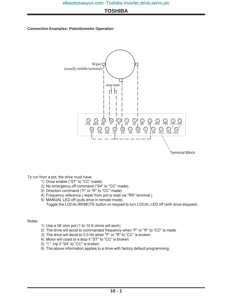
TOSHIBA
10 - 1
Terminal Block
ST FM AM CC CC RX PP IV FP FLC FLB FLA
P24 RES RR F R S1 S2 S3 S4 RCH LOWA
LOWC
To run from a pot, the drive must have:1) Drive enable ("ST" to "CC" made).2) No emergency off command ("S4" to "CC" made).3) Direction command ("F" or "R" to "CC" made)4) Frequency reference ( wiper from pot is read via "RR" terminal )5) MANUAL LED off (puts drive in remote mode).
Toggle the LOCAL/REMOTE button on keypad to turn LOCAL LED off (with drive stopped).
Notes:1) Use a 3K ohm pot (1 to 10 K ohms will work).2) The drive will accel to commanded frequency when "F" or "R" to "CC" is made.3) The drive will decel to 0.0 Hz when "F" or "R" to "CC" is broken.4) Motor will coast to a stop if "ST" to "CC" is broken.5) "E" trip if "S4" to "CC" is broken.6) The above information applies to a drive with factory default programming.
stop/start
Wiper(usually middle terminal)
Connection Examples: Potentiometer Operation
P24
efesotomasyon.com -Toshiba inverter,drive,servo,plc

TOSHIBA
10 - 2
Terminal Block
ST FM AM CC CC RX PP IV FP FLC FLB FLA
P24 RES RR F R S1 S2 S3 S4 RCH LOWA
LOWC
To follow a 4-20 mA signal, the drive must have:1) "IV" dipswitch to the right of phone jack on control board (immediately under keypad) set to "I"
position. "5/10" dipswitch has no effect in this scenario.2) No emergency off command ("S4" to "CC" made).3) Drive enable ("ST"-"CC" made)4) Direction command ("F" or "R" to "CC" made)5) Frequency reference ( 4-20 mA signal at "IV" terminal )6) MANUAL LED off ( puts drive in remote mode) Toggle the LOCAL/REMOTE button on keypad to turn LOCAL LED off.
Notes:1) The drive will accel to the commanded frequency when "F" or "R" to "CC" is made.2) The drive will decel to 0.0 Hz when "F" or "R" to "CC" is broken.3) Motor will coast to a stop if "ST" to "CC" is broken.4) "E" trip if "S4" to "CC" is broken.5) The above information applies to a drive with factory default programming.6) Do not connect "CC" to ground.
stop/start
I 5
V 10
Dipswitch
4-20 mA Reference
Phone Jack on Control Board
> (+)( - )
Connection Examples: 4 - 20mA Reference Operation Insp
ectio
n &
Prec
autio
nsO
pera
ting
Spec
ifica
tions
Wiri
ngEq
uipm
ent
Term
inal
Con
nect
ions
Ope
ratio
nPa
ram
eter
Spec
ifica
tions
Para
met
erEx
plan
atio
nsO
pera
tion
Serv
ice
&Tr
oubl
esho
otD
imen
sion
s &
Wei
ghts
Inde
xR
efer
ence
Pane
lM
odes
Ope
ratin
gEx
ampl
es
P24
efesotomasyon.com -Toshiba inverter,drive,servo,plc

TOSHIBA
10 - 3
< >
Pinout for E3 RJ11 RS232 port
(5) (4) (3) (2) (1)(9) (8) (7) (6)
Pinout for DB-9 on computer
( looking head-on at male connectorthat plugs into computer )
Notes:1) Free RS232 programming/monitoring software is available from Toshiba. Contact your
distributor for a copy and manual.2) Do not insert/remove the phone plug into/from the E3 port when drive is powered.3) Common 6 conductor phone cord can be used with an adaptor (6 conductor RJ11
female to DB9 female).The adapter is available from your Toshiba distributor or local electrical supply house.
4) "ST"-"CC" must be made.5) "S4"-"CC" must be made.
6 5 4 3 2 1
Connect DB9 pin 5 to RJ11 pin 3Connect DB9 pin 3 to RJ11 pin 4Connect DB9 pin 2 to RJ11 pin 2Connect DB9 pin 7 to RJ11 pin 6Connect DB9 pin 8 to RJ11 pin 1Short DB9 pin 6 to DB9 pin 4DB9 pin 1 and 9 and RJ11 pin 5 not used
To follow a local (keypad) frequency reference with a auto stop/run, the drive must have:1) Drive enable ("ST"-"CC" jumpered)2) No emergency off command ("S4" to "CC" made).3) Direction command ("F" or "R" to "CC" jumpered)4) Frequency reference: Adjust on keypad with arrows. Press READ/WRITE to enter.5) AUTO LED on ( puts drive in auto mode)6) Toggle the LOCAL/REMOTE key on keypad to turn LOCAL LED "on" or
Programming: Set Item 312, FREQUENCY MODE SELECTION (fmod) to Option 2.See page 8-31, 9-33.
Notes:1) The drive will accel to the commanded frequency when "F" or "R" to "CC" is made.2) The drive will decel to 0.0 Hz when "F" or "R" to "CC" is broken.3) Motor will coast to a stop if "ST" to "CC" is broken.4) "E" trip if "S4" to "CC" is broken.
Connection Examples: RS232 Port
Connection Examples: Keypad Frequency Reference and Remote Stop/Start
ST FM AM CC CC RX PP IV FP FLC FLB FLA
P24 RES RR F R S1 S2 S3 S4 RCH LOWA
LOWC Terminal Block
dry contact (stop/start)
P24
efesotomasyon.com -Toshiba inverter,drive,servo,plc

TOSHIBA
10 - 4
Terminal Block
ST FM AM CC CC RX PP IV FP FLC FLB FLA
P24 RES RR F R S1 S2 S3 S4 RCH LOWA
LOWC
To run from a 0-10 V reference, the drive must have:1) Drive enable ("ST"-"CC" made).2) No emergency off command ("S4" to "CC" made).3) Direction command ("F" or "R" to "CC" made)4) Frequency reference ( 0-10 V signal applied to "RR" terminal )5) MANUAL LED off (puts drive in remote mode).
Toggle the LOCAL/REMOTE button on keypad to turn LOCAL LED off.
Notes:1) The drive will accel to commanded frequency when "F" or "R" to "CC" is made.2) The drive will decel to 0.0 Hz when "F" or "R" to "CC" is broken.3) Motor will coast to a stop if "ST" to "CC" is broken.4) The above information applies to a drive with factory default programming.5) Do not connect "CC" to ground.6) "E" trip if "S4" to "CC" is broken.
< >Reference0-10 V
stop/start
(+) ( - )
Connection Examples: 0-10 volt Reference Operation Insp
ectio
n &
Prec
autio
nsO
pera
ting
Spec
ifica
tions
Wiri
ngEq
uipm
ent
Term
inal
Con
nect
ions
Ope
ratio
nPa
ram
eter
Spec
ifica
tions
Para
met
erEx
plan
atio
nsO
pera
tion
Serv
ice
&Tr
oubl
esho
otD
imen
sion
s &
Wei
ghts
Inde
xR
efer
ence
Pane
lM
odes
Ope
ratin
gEx
ampl
es
P24
efesotomasyon.com -Toshiba inverter,drive,servo,plc

TOSHIBA
10 - 5
Programming Examples:
Note: The drive will "kick out" of programming mode and return to the "output frequency" display whena parameter name is displayed for fourteen seconds after the previous parameter has been readand written.
See the chart on page 7-7 for a list of all drive groups.
Programming Example 1Objective: Set ACCELERATION TIME #1 (ACC1) to 23.4 seconds.We can change acceleration #1 in SETUP mode or in group FUNDAMENTALPARAMETERS #1 (gr.f).Assume we change the acceleration time #1 in SETUP mode.Step 1: Press S/P/M key and then R/W key to enter SETUP mode.Step 2: The first parameter is ACCELERATION TIME #1 (ACC1) . Press up or down key to
adjust the value to 23.4.Step 3: Press the R/W key to write the new value to EEPROM memory.
BlindingTo make the drive's many parameters more manageable, Toshiba employs "blinded" parametersand "blinded" groups.
BLINDED PARAMETERSItem 13, STALL PROTECTION LEVEL #1 (sel1), is an example of a "blinded" parameter. Ablinded parameter is identified in the parameter charts (which start on page 8-1) by its grayshading. A "blinded" parameter is preceded by a parameter that has a shaded choice in theAdjustment Range column like Item 12, STALL PROTECTION ENABLE #1 (sec1) . Item 13,(sel1), is visible to the programmer only if Item 12, (sec1) has the Option set to 0. Note howAdjustment Range 1 is not shaded to indicate this. There are many other blinded parametersin this drive.
BLINDED GROUPSOf the twenty groups available in the drive, ten are accessible when the drive is programmed withfactory defaults and ten are blinded. To adjust a parameter that is not in one of the visible groups,that parameter's group must first be added to the group list. This is done by turning "on" or "off"the BLIND FUNCTION SELECTION (blnd) parameter located in group UTILITYPARAMETERS (gr.ut), which is an always visible group.
Search FunctionWhen GROUP: PARAMETERS CHANGED FROM FACTORY DEFAULT (gr.U) is displayed andREAD/WRITE is pressed, the drive will flash gr.U and display any parameters that have beenchanged to a value different from the Toshiba factory set defaults. Press READ/WRITE to seethe value of the parameter. The parameter can be modified with the up/down arrows.Pressing READ/WRITE again resumes the drive's search.
efesotomasyon.com -Toshiba inverter,drive,servo,plc

TOSHIBA
10 - 6
Insp
ectio
n &
Prec
autio
nsO
pera
ting
Spec
ifica
tions
Wiri
ngEq
uipm
ent
Term
inal
Con
nect
ions
Ope
ratio
nPa
ram
eter
Spec
ifica
tions
Para
met
erEx
plan
atio
nsO
pera
tion
Serv
ice
&Tr
oubl
esho
otD
imen
sion
s &
Wei
ghts
Inde
xR
efer
ence
Pane
lM
odes
Ope
ratin
gEx
ampl
es
Programming Examples
Preset Speed ExampleThe following example uses "S1" and "S2" terminals to access three preset speeds of 11.0 Hz(close "S1"-"CC"), 55.0 Hz (close "S2"-"CC"), and 33.7 Hz (close "S1" and "S2" to "CC"). "F"-"CC"and "ST"-"CC" must be made on the drive's terminal strip. This example assumes Input terminal 1it1 = 1 and Input terminal 2 it2 = 2 prior to performing the following programming.
Group Parameter ValueUTILITY PARAMETERS GR.Ut BLIND FUNCTION SELECTION blnd 1UTILITY PARAMETERS GR.Ut FREQ SETTING PARAMETERS BLIND blsf 1FREQ SETTING PARAMETERS gr.sf PRESET SPEED SELECTION sr.n 3FREQ SETTING PARAMETERS gr.sf PRESET SPEED MODE ACTIVATION sr.m 0FREQ SETTING PARAMETERS gr.sf PRESET SPEED #1 FREQUENCY fsor 11FREQ SETTING PARAMETERS gr.sf PRESET SPEED #1 OPERATING MODE srm1 0FREQ SETTING PARAMETERS gr.sf PRESET SPEED #2 FREQUENCY sr02 55FREQ SETTING PARAMETERS gr.sf PRESET SPEED #2 OPERATING MODE srm2 0FREQ SETTING PARAMETERS gr.sf PRESET SPEED #3 FREQUENCY sr03 33.7FREQ SETTING PARAMETERS gr.sf PRESET SPEED #3 OPERATING MODE srm3 0
Trim Pot ExampleThis example uses the "RX" terminal to trim a reference (i.e. a 4-20 mA input) +7/-5 Hz.
Group Parameter ValueUTILITY PARAMETERS GR.Ut BLIND FUNCTION SELECTION blnd 1UTILITY PARAMETERS GR.Ut FEEDBACK CONTROL PARAMETERS BLIND blfb 1UTILITY PARAMETERS GR.Ut FREQ SETTING PARAMETERS BLIND blsf 1FEEDBACK PARAMETERS GR.fb OVERRIDE CONTROL SELECT 0rd1 3FREQ SETTING PARAMETERS gr.sf RX TERMINAL STANDARD OR ADJUSTABLE inrr 1FREQ SETTING PARAMETERS gr.sf RX INPUT REF SETTING POINT #1 p1 0 %FREQ SETTING PARAMETERS gr.sf RX REF POINT #1 OUTPUT FREQUENCY f-p1 7 HZFREQ SETTING PARAMETERS gr.sf RX INPUT REF SETTING POINT #2 p2 100 %FREQ SETTING PARAMETERS gr.sf RX REF POINT #2 OUTPUT FREQUENCY f-p2 -5 HZ
Motor Operated Pot (MOP) or Floating Point ControlThe following programming allows a drive to emulate motor operated pot control. Momentarilyshorting "S1"-"CC" increases frequency reference. Momentarily shorting "S2"-"CC" decreasesfrequency reference. Momentarily shorting "S3"-"CC" erases frequency reference. "F"-"CC" and"ST"-"CC" must be made on the drive's terminal strip. This example assumes drive is defaulted tofactory settings prior to the following programming is done.
Group Parameter ValueUTILITY PARAMETERS GR.Ut BLIND FUNCTION SELECTION blnd 1UTILITY PARAMETERS GR.Ut FREQ SETTING PARAMETERS BLIND blsf 1TERM SELECT PARAMETERS GR.st INPUT TERMINAL SELECTION it 1TERM SELECT PARAMETERS GR.st "S1" INPUT TERMINAL FUNCTION it1 34TERM SELECT PARAMETERS GR.st "S2" INPUT TERMINAL FUNCTION it2 35TERM SELECT PARAMETERS GR.st "S3" INPUT TERMINAL FUNCTION it3 36FREQ SETTING PARAMETERS gr.sf FREQUENCY PRIORITY SELECTION #1 fc1 5
efesotomasyon.com -Toshiba inverter,drive,servo,plc

TOSHIBA
10 - 7
Programming Examples (cont'd)
True Torque Control ProgrammingAlthough not required for variable torque applications, this drive can be programmed to utilize TrueTorque Control (TTC), the benefits of which are slip compensation and high torque at low speed. In voltsper hertz control (or across the line ), a typical AC induction motor will lose 3-5% of its RPM as it goesfrom no load to full load; when operated in TTC mode, a motor will slow a maximum of 0.5% of base RPMas it is loaded. Motors operated on volts per hertz drives cannot develop their rated torque when operatedat low frequencies..
The drive divides the motor current it is providing into two components that are ninety degrees out ofphase: the excitation current and the torque current. Excitation current is the part of the total current thatdevelops the magnetic field in the motor's core. The torque current is the current that does the usefulwork. According to the Pythagorean theorem, (total current)2 = (torque current)2 + (excitation current)2.The drive calculates and controls these currents based on motor models to optimize motor performance.
If a Toshiba/Houston motor is used, the drive will use an on-board motor model. If a generic motor isused, the drive can be programmed to auto-tune. During auto tuning, the drive derives a motor model byapplying a voltage to the motor and analyzing the resulting decay.
These parameters must be adjusted to use TTC with a TOSHIBA/HOUSTON motor.
Group Parameter Value UTILITY PARAMETERS GR.Ut BLIND FUNCTION SELECTION blnd 1 UTILITY PARAMETERS GR.Ut MOTOR PARAMETERS BLIND blnt 1 FUNDAMENTAL PARAMETERS #1 gr.f VOLTS PER FREQUENCY PATTERN pt 5 MOTOR PARAMETERS gr.mt NUMBER OF MOTOR POLES mt.p * MOTOR PARAMETERS gr.mt MOTOR RATED CAPACITY mt.c * MOTOR PARAMETERS gr.mt MOTOR TYPE mt.t ** MOTOR PARAMETERS gr.mt LOAD MOMENT OF INERTIA mt.1H ***
The following parameters must be adjusted to use TTC for a GENERIC motor.
Group Parameter Value UTILITY PARAMETERS GR.Ut BLIND FUNCTION SELECTION blnd 1 UTILITY PARAMETERS GR.Ut MOTOR PARAMETERS BLIND blnt 1 FUNDAMENTAL PARAMETERS #1 gr.f VOLTS PER FREQUENCY PATTERN pt 5 MOTOR PARAMETERS gr.mt NUMBER OF MOTOR POLES mt.p * MOTOR PARAMETERS gr.mt MOTOR RATED CAPACITY mt.c * MOTOR PARAMETERS gr.mt MOTOR TYPE mt.t 2 MOTOR PARAMETERS gr.mt MOTOR RATED VOLTAGE mt.v * MOTOR PARAMETERS gr.mt MOTOR RATED FREQUENCY mt.t * MOTOR PARAMETERS gr.mt MOTOR RATED RPM mt.r * MOTOR PARAMETERS gr.mt AUTO-TUNING ENABLE mt.tn 1**** MOTOR PARAMETERS gr.mt LOAD MOMENT OF INERTIA mt.1H ***
* Enter appropriate value from motor's nameplate. KW = 0.746 X HP.** Enter "0" for an EQPIII or "1" for a high efficiency motor.
**** The drive will auto tune the next time a run is initiated. This parameter is then reset to "0" by the drive`.
efesotomasyon.com -Toshiba inverter,drive,servo,plc

TOSHIBA
11 - 1
Requesting ServiceWhen requesting service, report the contents of the following problem information sheet.
Problem Information Sheet
ItemCustomer's name
Refer to Person in chargeAddressTelephone No.
Drive Model No.spec. Serial No.
Test No.Delivery dateTime in serviceDate when problem arose
UseMotor rating Poles, Hp, V, Hz.
Made by Toshiba? Made by another company?New? Number of units?Alternate? Continuous?
Status of Indoor? Outdoor? Temperature range?Use Ambient Humidity:
condition Dust composition and size:Presence of salt and extent of corrosion from it:Vibrations, in micrometers:Presence of corrosive gas:Availability of air conditioning:Number of phases:Voltage between L1 phase and L2 phase:
Power Voltage between L2 phase and L3 phase:source Voltage between L3 phase and L1 phase:
Number of Hz:Problem occurred hours after motor had been started. Motor hasbeen stopped for hours.
Phenome- State of Problem occurred during periodic inspection?non motor when Problem occurred when motor was started?
problem was Problem occurred during acceleration?found Problem occurred during deceleration?
Problem occurred while motor was not running?Frequency First time? Problem occurred times in the past.of problem Problem occurs sometimes?
Problem occurs every time motor is operated?When did problem first occur?
Troubleindicator
Detailed description of problem:
Temporary diagnosis and corrective action:
Date defective product shipped: To:Deadline for repairs:
Indicate LED Message:
Only qualified personnel should be allowed to service this equipment.
Insp
ectio
n &
Prec
autio
nsO
pera
ting
Spec
ifica
tions
Wiri
ngEq
uipm
ent
Term
inal
Con
nect
ions
Ope
ratio
nPa
ram
eter
Spec
ifica
tions
Para
met
erEx
plan
atio
nsO
pera
tion
Serv
ice
&Tr
oubl
esho
otD
imen
sion
s &
Wei
ghts
Inde
xR
efer
ence
Pane
lM
odes
Ope
ratin
gEx
ampl
es
efesotomasyon.com -Toshiba inverter,drive,servo,plc

TOSHIBA
11 - 2
Parts Service LifeIn order to obtain the best performance and to get the maximum service life from the drive itis necessary to perform timely maintenance repairs on some parts of the system even thoughthe equipment may still be functioning with no apparent problems.
Use the following service life chart as a guide for major part periodic replacement when theequipment is used in a standard installation service environment.
Service Life Replacement Chart
Part Name Service Life Remarks
Large capacity 5 Years To be electrified semiannually inelectrolytic capacitor case of long term disuse.
Cooling Fan 26000 Hours Internal fans(included on some models)
Contact relays 500,000 operations
Connectors 100 operations Replace pin in case of failure.
efesotomasyon.com -Toshiba inverter,drive,servo,plc

TOSHIBA
11 - 3
Troubleshooting
If the drive faults, the following questions may help to pinpoint the reason for the trip:1. Does the drive trip when accelerating, running, decelerating, or when not running ?2. Can the drive make it to commanded frequency ?3. Does the drive trip without the motor attached ?4. Does drive trip with an unloaded motor ?
Drive data at the time of trip is saved in the monitor and can be read until the trip is cleared. Beforeclearing the trip, make a note of this information. A history of past faults can be viewed by pressing theMON button and then the down arrow until PAST FAULTs are displayed. Some trips are the result ofimproper programming; resetting the drive to factory settings may be a solution (see Item 17, STANDARDSETTING MODE SELECTION typ).
How to clear a fault1. Cycling power2. Pressing the STOP/RESET button twice3. Closing "RES"-"CC" on the terminal strip (with default drive programming).
If Item 191, FAULT TRIP SAVING trcl is set to option "1", the drive will power up with the fault display,but the fault monitor and any fault contacts will be reset. On OVERLOAD trips, reset can occur only after acooling time; see explanation for Item 14, OVERLOAD SELECTION 0lm. No cooling time for reset isrequired when power is cycled.
RETRYSee Items 172, RETRY SELECTION rtry and Item 173, RETRY TIME SETTING rtt to programdrive to automatically attempt to reset faults. Drive will display rtry "flashing" during retries. Seepage 9-14 for a list of faults to retry. Retry will not function if Item 172, rtry is set to "1" (on).
The keypad, control board (with phone jack), and terminal strip board are common to all driveratings. If a board or keypad is suspect, exchange with a known good board/keypad to verify.
Drive Fault Displays and Explanations
OVERCURRENT (ACCEL) 0c1 or DC OVERCURRENT (ACC) 0c1pCause: Drive current exceeded 145% of its rated FLA (190% above 100 HP).Comments: Check for phase-phase short. ACCELERATION TIME acc1 or acc2 may betoo small. VOLTAGE BOOST vb1 or vb2 may be too high. Is motor/machine jammed? Ismechanical brake engaged while drive is running? If drive is starting into a rotating motor, seeItem 176, AUTO-RESTART arst . If there is a contactor between motor and drive, wire sothat contactor changes state only when drive is outputting 0.0 Hz. Drive will automatically adjustaccel time with Item 30, ACC/DEC PATTERN #1 scu1 set to option "1".
OVERCURRENT (DECEL) 0c2 or DC OVERCURRENT (DEC) 0c2pCause: Drive current exceeded 145% of its rated FLA.Comments: Check for phase-phase short. DECELERATION TIME dec1 or dec2 may be toosmall. Is motor/machine jammed? Is mechanical brake engaged while drive is running? Addingappropriate braking resistor across "PA" and "PB" terminals may solve problem (see page 9-20).Drive will automatically adjust decel time with Item 30, ACC/DEC PATTERN #1 scu1 optionset to "1".
OVERCURRENT (RUN) 0c3 or DC OVERCURRENT (RUN) 0c3pCause: Drive current exceeded 145% of its rated FLA.Comments: Check for phase-phase short. Is motor/machine jammed? Is mechanical brakeengaged while drive is running? Adding appropriate dynamic braking resistor across "PA" and"PB" terminals may solve problem (see page 9-20). If there are severe load fluctuations, addingmechanical dampening or an output line reactor may help to electrically dampen.
Insp
ectio
n &
Prec
autio
nsO
pera
ting
Spec
ifica
tions
Wiri
ngEq
uipm
ent
Term
inal
Con
nect
ions
Ope
ratio
nPa
ram
eter
Spec
ifica
tions
Para
met
erEx
plan
atio
nsO
pera
tion
Serv
ice
&Tr
oubl
esho
otD
imen
sion
s &
Wei
ghts
Inde
xR
efer
ence
Pane
lM
odes
Ope
ratin
gEx
ampl
es
efesotomasyon.com -Toshiba inverter,drive,servo,plc

TOSHIBA
11 - 4
Drive Fault Displays and Explanations (cont'd)
U-PHASE SHORT-CIRCUIT 0ca1 or V PHASE SHORT-CIRCUIT 0ca2 or W PHASESHORT-CIRCUIT 0ca3
Cause: Drive detected short-circuit in transistor.Comments: Replace transistor. Contact your Toshiba distributor for authorized repair.
LOAD-END OVERCURRENT0clCause: Drive detected short-circuit on output.Comments: Check for phase-phase short. Meg motor/leads with leads disconnected fromdrive . Remove any power factor correction caps on motor. See Item 169, OUTPUT SHORT-CIRCUIT DETECTION SELECT .
OVERVOLTAGE (ACCEL) 0p1 or OVERVOLTAGE (RUN) 0cp3Cause: Bus exceeded 393 VDC (230 volt drive),or 787 VDC (460 volt drive).Comments: Incoming AC may have gone high or spiked (verify with Item 319,320, 321, or 322set to option "16"); a line reactor or a lower tap on transformer may help. Motor may bemechanically forced to run faster than drive is commanding; install appropriate dynamic brakingresistor (see page 9-20). On eccentric cyclic loads like presses or pump jacks, contact yourToshiba distributor for special programming instructions that may make a DBR unnecessary.
OVERVOLTAGE (DEC) 0cp2Cause: Bus exceeded 393 VDC (230 volt drive),or 787 VDC (460 volt drive).Comments: Incoming AC may have gone high or spiked (verify with Item 319 set to option "16");a line reactor or a lower tap on transformer may help. Item 2, DECELERATION TIME #1 0cp2may be too short. Drive will automatically change decel time with Item 31, ACC/DEC PATTERNADJUST LOW scl option set to "1". Make sure Item 164, OVERVOLTAGE STALLPROTECTION 0p55 is set to option "0". Motor may be mechanically forced to run faster than driveis commanding (due to large load inertias mechanical couplings); install appropriate dynamicbraking resistor (see page 9-20). On eccentric cyclic loads like presses or pump jacks, contactyour Toshiba distributor for special programming instructions that may make a DBR unnecessary.
INVERTER OVERLOAD 0l1nCause: Drive exceeded 100% of its rated current for too long of a time.Comments: This trip indicates that the drive output exceeded its rated current for specificamounts of time. For example, drives can output 110% of their rated current for 60 seconds, and150% for 0.5 seconds. If using DC Injection, Item 166, DC INJECTION CURRENT dbc or Item167 DC INJECTION TIME dbt they may be too large. If Item 98, PWM CARRIER FREQUENCYcf is greater than 8 KHz, try carrier frequencies less than 8 KHz. Programming Item 14, OVERLOAD SELECTION 0lm to option"1" or "3" (soft stall on) makes the drive reduce outputfrequency/voltage to shed load (works best on variable torque applications). Motor or loadbearings may have seized. Enabling True Torque Control (see page 10-7) may reduce drive'scurrent output and solve the problem. Make sure that drive is seeing voltage on all three inputphases. Drive may be undersized.
MOTOR OVERLOAD 0lmtCause: Motor is in danger of overheating because it drew too much current for too long of a time,as determined by the drive.Comments: See page 8-14. Check Items 178, 179, 180, and 181. If trip occurred at a lowfrequency, the setting of Item 179, OVERLOAD REDUCTION START FREQUENCY 0lf is probablycritical. Motor overload protection can be turned off by placing a "2" or "3" in Item 181. Checkvalue in Item 180, MOTOR 110% OVERLOAD TIME LIMIT 0lt.
efesotomasyon.com -Toshiba inverter,drive,servo,plc

TOSHIBA
11 - 5
Drive Fault Displays and Explanations (cont'd)
DBR OVERCURRENT 0crCause: IGBT7 (dynamic braking transistor) is damagedComments: Check ohm value connected to "PA" and "PB" terminals (see page 9-20 for minimumohm values). If using multiple resistors, make sure parallel-series combination is wired correctly.Check IGBT7. Check DC bus fuse for continuity; if open, check output transistors. Consult yourToshiba distributor for authorized service.
DBR OVERLOAD 0lrCause: Dynamic braking resistor is in danger of overheating (as determined by drive).Comments: Check that the values entered into Item 162, BRAKING RESISTOR VALUE pbr andItem 163, BRAKING RESISTOR CAPACITY pbcp are correct.
OVERHEAT 0HCause: Drive's heatsink exceeded 90o C.Comments: Check drive's muffin fans (if any). Clear heatsinks of anything blocking airflow.The enclosure that the drive is installed in may be too small or there may be to many heat sourcesin the same enclosure. Drive may not have been properly sized for operating altitude. Thermistoron heatsink may be bad.
EMERGENCY OFF ECause: Drive received one of the following ESTOP commands:1. Drive was receiving STOP/RUN command via terminal strip when STOP button on keypad was pressed.2. One of the drive's input terminal's function is set to "10" (see Item codes 0-56 and page 9-11),and terminal is being opened/closed to command ESTOP.
EEPROM WRITE FAILURE or EEPROM READ FAILURE eep1, eep2Cause: EEPROM was unable to read/write to peripherals.Comments: Check for miswiring that may be causing noise (such as "CC" connected to ground,an external 10 volt source connected to "PP" etc.) Control board may need to be replaced.See picture of board on page 5-2.
RAM ERROR or ROM ERROR err3, err4Comments: Check for miswiring that may be causing noise (such as "CC" connected to ground,an external 10 volt source connected to "PP" etc.). Replace control board. See picture of boardon page 5-2.
OPTION ROM ERROR err9Comments: Check for miswiring that may be causing noise (such as "CC" connected to ground,an external 10 volt source connected to "PP" etc.). If drive is energized with option ROM installedand is later energized without option ROM installed, this fault will appear. Reset in normal fashion.
CPU ERROR err4Comments: If option ROM or option board is installed or removed when drive is powered, thisfault will appear. Reset like any fault. Check for miswiring that may be causing noise (such as"CC" connected to ground, an external 10 volt source connected to "PP" etc.). If the CPU is trulydamaged, the fault will not reset and replacement of the control board is necessary. See pictureof control board on page 5-2.
COMMUNICATION ERROR err5Cause: RS232 or RS485 timer did not respondComments: Check wiring to RS232 or RS485 ports. Check setting of Item 286,COMMUNICATION SELECTION 0pt (should be option "1" for RS485). Check jumpers J1, J2,and J3 on RS485 option board (see RS485 Communications Option Manual). Cable may bebroken.
Insp
ectio
n &
Prec
autio
nsO
pera
ting
Spec
ifica
tions
Wiri
ngEq
uipm
ent
Term
inal
Con
nect
ions
Ope
ratio
nPa
ram
eter
Spec
ifica
tions
Para
met
erEx
plan
atio
nsO
pera
tion
Serv
ice
&Tr
oubl
esho
otD
imen
sion
s &
Wei
ghts
Inde
xR
efer
ence
Pane
lM
odes
Ope
ratin
gEx
ampl
es
efesotomasyon.com -Toshiba inverter,drive,servo,plc

TOSHIBA
11 - 6
Drive Fault Displays and Explanations (cont'd)
OPTION PCB ERROR err8Comments: If drive is energized with an option board installed and is later energized withoutthe board installed, this fault will appear. Check connectors between control board and optionboard. Check settings of Item 99, FREQUENCY PRIORITY SELECTION #1 fc1, Item 100,FREQUENCY PRIORITY SELECTION #2 fc2, and Item 286, COMMUNICATIONSELECTION 0pt. Use stand-offs to secure board.
LOW CURRENT TRIP UcCause: The drive's output current went below the current value entered in Item 186, LOWCURRENT DETECT LEVEL llpc for at least the amount of time entered in Item 187, LOWCURRENT DETECTION TIME llpt.
UNDERVOLTAGE TRIP Up1Cause: The drive's DC bus voltage went below 217 VDC (230 V E3), or 413 VDC (460 V E3),for at least the time entered in Item 185, UNDERVOLTAGE DETECT TIME Upt.Comments: Item 184, UNDERVOLTAGE TRIP SELECTION Up5l turns the ability toundervoltage trip on/off. On models 2080-2110 and 4080-4270, turning on Item 174,REGENERATION POWER RIDE-THROUGH Uuc and adjusting Item 175, REGENERATIONRIDE-THROUGH TIME Uuct may keep bus up during brown out if there is sufficient regenenergy from the load.
OVERTORQUE TRIP 0tCause: The drive's torque current went above the current value programmed in Item 190,OVERTORQUE TRIP LEVEL 0tl. The drive can be programmed to torque current limit; contactyour Toshiba distributor and request the torque limit application guideline.
EARTH FAULT (SOFT) or EARTH FAULT (HARD) ef1, ef2Cause: Drive detected some current to ground. Depending on rating, drive senses ground fault viaZCT (hard fault) or HCT (soft fault).Comments: With leads disconnected from drive, meg motor and leads. Look for any moisture thatmay provide current path to ground. Make sure that control wiring is separated from power wiring.Adding noise supressors on coils of starters on same line as drive may snub noise picked up byZCT. RF/EMI filter may help remove noise generated by SCR rectifiers in the vicinity. Make suredrive chassis and motor are grounded.
AUTO-TUNING ERROR etnCause: Motor's physical characteristics are not within the window of allowable values for modeling.Comments: Try a different inertia setting in Item 353, LOAD MOMENT OF INERTIA mt.1H.Motor must be at rest to perform auto-tuning. Motor must be one HP size within the drive's HPsize. Auto-tuning is best done with motor at full-load temperature (if temperature is very cold,auto-tune error may appear).
GATE ARRAY FAULT err6Comments: Replace control board.
CURRENT DETECT ERROR err7Comments: Occurs when drive is stopped but CPU detects current flowing. This fault could becaused by plugging in RS232 cable with drive powered (resulting in damage to control board).Adding a RF/EMI filter may remove noise spikes from nearby SCR rectifiers. If the control boardis damaged, the drive must be serviced.
INV TYPEFORM ERROR etypCause: Control board is not configured to drive's rating.Comments: Enter option "7" into Item 310, STANDARD SETTING MODE SELECTION typ.
efesotomasyon.com -Toshiba inverter,drive,servo,plc

TOSHIBA
11 - 7
Drive Warning Displays and Explanations
DAMPER TRIP dampCause: Damper function is selected (one input terminal is assigned to 56 and one outputterminal is assigned to 64). Every time a run command is issued, the output terminal will outputa signal to open damper. Then waiting for the damper open full signal from the input terminal.After getting the damper open full signal from the input terminal, the motor will start to run. If thedamper is closed while the motor is running, go damper trip.Comments: Check the input damper status signal.
IV ANALOG INPUT LOSS TRIP l0ssCause: la15 = 3 and IV input voltage is less than 1 volt.Comments: Check IV input voltage.
DC BUS UNDERVOLTAGE m0ffCause: The drive's DC bus voltage went below approximately 217 VDC (230 volt drive), or413 VDC (460 volt drive), for at least the time entered in Item 184, UNDERVOLTAGE DETECTTIME UPt.Comments: Item 164, UNDERVOLTAGE TRIP SELECTION turns the ability to undervoltage tripon/off.
CONTROL POWER LOW p0ffControl Power low warning voltage levels are sensed on DC bus and are set slightly less thanDC BUS UNDERVOLTAGE m0ff levels.
OVERLOAD LA flashing overcurrent display means that the drive is outputting more than 110% of its ratedcurrent. If Item 14, OVERLOAD SELECTION 0lm is set to "1" or "3" (soft stall on), the drive'soutput frequency will automatically decrease in an effort to reduce current. See suggestions forremedying an inverter overload trip on page 11-4. Setting one of the monitor's functions (Items319-322) to "10" will give an indication of how close a drive is to tripping.
OVERCURRENT CA flashing overcurrent display means that the drive is stalling. (Stall level is set by Item 13,STALL PROTECTION CURRENT LEVEL sel1 ). The drive's output frequency will automaticallydecrease.
OVERVOLTAGE PA flashing overvoltage display means that the drive's DC bus has exceeded 360 VDC (230 voltdrive), or 720 VDC (460 volt drive).
OVERHEAT HA flashing overheat display means that the drive's heat sink temperature has exceeded 84oC.Display dissappears when heatsink temperature reaches 80oC.
COMM tA flashing comm display means that the drive has momentarily lost communications. Display willclear when follower receives valid reference. Cycling power or reinitializing drive will clear warning.
Insp
ectio
n &
Prec
autio
nsO
pera
ting
Spec
ifica
tions
Wiri
ngEq
uipm
ent
Term
inal
Con
nect
ions
Ope
ratio
nPa
ram
eter
Spec
ifica
tions
Para
met
erEx
plan
atio
nsO
pera
tion
Serv
ice
&Tr
oubl
esho
otD
imen
sion
s &
Wei
ghts
Inde
xR
efer
ence
Pane
lM
odes
Ope
ratin
gEx
ampl
es
efesotomasyon.com -Toshiba inverter,drive,servo,plc

TOSHIBA
11 - 8
Input terminal 4 (S3)
Input terminal 3 (S2)
Input terminal 2 (S1)Input terminal 1 (R)
Input terminal 5 (S4)
Always 1 (OFF)
1 when ON
1 when OFF(upper half blank)
Input terminal 9 (S5)
Input terminal 8 (ST)
Input terminal 7 (RES)Input terminal 6 (F)
'B' group (input terminals 6 to 11)
: b 11 11 11
1 when ON
1 when OFF(upper half blank)
Input terminal 10 (S6)
Drive Input and Output Terminal Information Decoding
Input terminal informationThe eleven input terminals correspond to the following bits.
'A' group (input terminals 1 to 5)
: a 11 11 11
Input terminal 10 (S7)
Output terminal information(Including status display of colling fan and main contactor for initial charging circuit)
The four output terminals correspond to the following bits. The operating status of thecooling fan and main contactor for the initial charging circuit are also displayed.
: 0 11 11 11
Output terminal 4 (OUT)
Output terminal 3 (FL)
Output terminal 2 (LOW)Output terminal 1 (RCH)
Cooling fan ON/OFF status
1 when ON
1 when OFF(upper half blank)
Main contactor for initial charging circuit status
Note:Output terminal 4 (OUT): Option PCB
efesotomasyon.com -Toshiba inverter,drive,servo,plc

TOSHIBA
Basic Dimensions
FIGURE 2
Insp
ectio
n &
Prec
autio
nsO
pera
ting
Spec
ifica
tions
Wiri
ngEq
uipm
ent
Term
inal
Con
nect
ions
Ope
ratio
nPa
ram
eter
Spec
ifica
tions
Para
met
erEx
plan
atio
nsO
pera
tion
Serv
ice
&Tr
oubl
esho
otD
imen
sion
s &
Wei
ghts
Inde
xR
efer
ence
Pane
lM
odes
Ope
ratin
gEx
ampl
es
FIGURE 2FIGURE 1
4.50
4.08
4.08
4.50
FF
D E A
C
G
BH
G
D E A
CBH
.25
.25
2-"K" DIA.2-"K" DIA.
2-SLOT "J" DIA.
2-SLOT "J" DIA.
DIMENSIONS in inches(millimeters)
12 - 1
MODEL FIG A B C D E F G H J KVT130E3U2035 1 13.13(334) 8.67(220) 7.92(201) 12.10(307) 12.43(316) 7.31(186) 8.08(205) 4.34(110) .28(7) .28(7)VT130E3U2055 1 13.13(334) 8.67(220) 7.92(201) 12.10(307) 12.43(316) 7.31(186) 8.08(205) 4.34(110) .28(7) .28(7)VT130E3U2080 1 17.84(453) 10.22(260) 8.92(227) 16.72(425) 17.25(438) 8.87(225) 12.05(306) 5.11(130) .28(7) .28(7)VT130E3U2110 1 17.84(453) 10.22(260) 8.92(227) 16.72(425) 17.25(438) 8.87(225) 12.05(306) 5.11(130) .28(7) .28(7)VT130E3U2160 1 17.84(453) 10.22(260) 8.92(227) 16.72(425) 17.25(438) 8.87(225) 12.05(306) 5.11(130) .28(7) .28(7)VT130E3U2220 1 21.50(546) 15.41(391) 10.50(267) 19.78(502) 20.63(524) 12.13(308) 10.68(271) 7.96(202) .44(11) .44(11)VT130E3U2270 1 21.50(546) 15.41(391) 10.50(267) 19.78(502) 20.63(524) 12.13(308) 10.68(271) 7.96(202) .44(11) .44(11)VT130E3U2330 1 21.50(546) 15.41(391) 10.50(267) 19.78(502) 20.63(524) 12.13(308) 10.68(271) 7.96(202) .44(11) .44(11)VT130E3U2400 2 32.50(826) 19.25(489) 13.56(344) 29.56(751) 31.34(796) 12.63(321) 20.52(521) 9.63(245) .63(16) .63(16)VT130E3U2500 2 32.50(826) 19.25(489) 13.56(344) 29.56(751) 31.34(796) 12.63(321) 20.52(521) 9.63(245) .63(16) .63(16)VT130E3U2600 2 36.50(927) 19.25(489) 13.56(344) 33.56(852) 35.34(898) 12.63(321) 22.52(572) 9.63(245) .63(16) .63(16)VT130E3U4055 1 14.64(372) 8.67(220) 7.92(201) 13.53(344) 14.06(357) 7.31(186) 9.56(243) 4.34(110) .28(7) .28(7)VT130E3U4080 1 14.64(372) 8.67(220) 7.92(201) 13.53(344) 14.06(357) 7.31(186) 9.56(243) 4.34(110) .28(7) .28(7)VT130E3U4110 1 14.64(372) 8.67(220) 7.92(201) 13.53(344) 14.06(357) 7.31(186) 9.56(243) 4.34(110) .28(7) .28(7)VT130E3U4160 1 17.84(453) 10.22(260) 8.92(227) 16.72(425) 17.25(438) 8.87(225) 12.05(306) 5.11(130) .28(7) .28(7)VT130E3U4220 1 17.84(453) 10.22(260) 8.92(227) 16.72(425) 17.25(438) 8.87(225) 12.05(306) 5.11(130) .28(7) .28(7)VT130E3U4270 1 18.63(473) 15.41(391) 10.50(267) 17.28(439) 17.94(456) 12.13(308) 8.46(215) 7.96(202) .38(10) .38(10)VT130E3U4330 1 18.63(473) 15.41(391) 10.50(267) 17.28(439) 17.94(456) 12.13(308) 8.46(215) 7.96(202) .38(10) .38(10)VT130E3U4400 1 21.50(546) 15.41(391) 10.50(267) 19.78(502) 20.63(524) 12.13(308) 10.68(271) 7.96(202) .44(11) .44(11)VT130E3U4500 1 21.50(546) 15.41(391) 10.50(267) 19.78(502) 20.63(524) 12.13(308) 10.68(271) 7.96(202) .44(11) .44(11)VT130E3U4600 2 32.50(826) 19.25(489) 13.56(344) 29.56(751) 31.34(796) 12.63(321) 20.52(521) 9.63(245) .63(16) .63(16)VT130E3U4750 2 32.50(826) 19.25(489) 13.56(344) 29.56(751) 31.34(796) 12.63(321) 20.52(521) 9.63(245) .63(16) .63(16)VT130E3U410K 2 32.50(826) 19.25(489) 13.56(344) 29.56(751) 31.34(796) 12.63(321) 20.52(521) 9.63(245) .63(16) .63(16)VT130E3U412K 2 36.50(927) 19.25(489) 13.56(344) 33.56(852) 35.34(898) 12.63(321) 22.52(572) 9.63(245) .63(16) .63(16)
efesotomasyon.com -Toshiba inverter,drive,servo,plc

12 - 2
TOSHIBA
Basic Dimensions
DIMENSIONS in inches(millimeters)
FIGURE 2
FIGURE 3
4.08
4.50
F
D E A
C
G
BH
.25
2-"K" DIA.
2-SLOT "J" DIA.
MODEL FIG A B C D E F G H J KVT130E3U6060 3 18.75(476) 14.38(365) 9.94(252) 17.13(435) 18.09(459) 11.25(286) 10.34(263) 7.87(200) .38(10) .38(10)VT130E3U6120 3 20.75(527) 14.38(365) 9.94(252) 19.13(486) 20.09(510) 11.25(286) 10.84(275) 7.87(200) .38(10) .38(10)VT130E3U6160 3 23.63(600) 17.38(441) 11.50(292) 21.63(549) 22.75(578) 14.25(362) 14.84(377) 9.38(238) .50(13) .50(13)VT130E3U6220 3 23.63(600) 17.38(441) 11.50(292) 21.63(549) 22.75(578) 14.25(362) 14.84(377) 9.38(238) .50(13) .50(13)VT130E3U6270 3 23.63(600) 17.38(441) 11.50(292) 21.63(549) 22.75(578) 14.25(362) 14.84(377) 9.38(238) .50(13) .50(13)VT130E3U6330 3 36.50(927) 19.25(489) 13.56(344) 33.88(861) 35.34(898) 12.63(321) 21.49(546) 9.13(232) .63(16) .63(16)VT130E3U6400 3 36.50(927) 19.25(489) 13.56(344) 33.88(861) 35.34(898) 12.63(321) 21.49(546) 9.13(232) .63(16) .63(16)VT130E3U6500 3 36.50(927) 19.25(489) 13.56(344) 33.88(861) 35.34(898) 12.63(321) 21.49(546) 9.13(232) .63(16) .63(16)VT130E3U6600 3 36.50(927) 19.25(489) 13.56(344) 33.88(861) 35.34(898) 12.63(321) 21.49(546) 9.13(232) .63(16) .63(16)VT130E3U6750 3 36.50(927) 19.25(489) 13.56(344) 33.88(861) 35.34(898) 12.63(321) 21.49(546) 9.13(232) .63(16) .63(16)VT130E3U610K 3 57.00(1448) 19.25(489) 13.16(334) 54.16(1376) 55.81(1418) 12.63(321) 26.95(685) 9.62(244) .69(18) .69(18)VT130E3U612K 3 57.00(1448) 19.25(489) 13.16(334) 54.16(1376) 55.81(1418) 12.63(321) 26.95(685) 9.62(244) .69(18) .69(18)
efesotomasyon.com -Toshiba inverter,drive,servo,plc

TOSHIBA
12 - 3
Ope
ratin
gSp
ecifi
catio
nsW
iring
Equi
pmen
tTe
rmin
alC
onne
ctio
nsO
pera
tion
Para
met
erSp
ecifi
catio
nsPa
ram
eter
Expl
anat
ions
Ope
ratio
nSe
rvic
e &
Trou
bles
hoot
Dim
ensi
ons
&W
eigh
tsIn
dex
Ref
eren
cePa
nel
Mod
esO
pera
ting
Exam
ples
Shipping Weights
E3 Shipping Weight E3 Shipping WeightModel Pounds Kg Model Pounds Kg2035 17 7.7 4055 22 10.02055 18 8.2 4080 22 10.02080 26 11.8 4110 22 10.02110 28 12.7 4160 30 13.62160 29 13.2 4220 30 13.62220 67 30.4 4270 55 24.92270 70 31.8 4330 58 26.42330 72 32.7 4400 72 32.72400 176 79.8 4500 75 34.02500 180 81.6 4600 183 83.02600 200 90.7 4750 186 84.46060 20 9 410K 190 86.26120 61 28 412K 210 95.36160 65 306220 67 316270 110 506330 110 506400 111 516500 190 866600 196 896750 200 91610K 302 137612K 304 138
Insp
ectio
n &
Prec
autio
ns
efesotomasyon.com -Toshiba inverter,drive,servo,plc

TOSHIBA
13 - 1
INDEX
AAcc/dec #1/#2 selection ..................................... ad2 ................................................................ 8-4,9-6Acc/dec #1/#2 switching frequency .................... ad2f .............................................................. 8-3,9-5Acc/dec complete detection bandwidth ............... brcH .............................................................. 8-6,9-9Acc/dec pattern #1, #2 ..................................... scu1, scu2 ............................................. 8-2,8-3,9-4,9-5Acc/dec pattern adjustment amounts (high) ........ scH ................................................................ 8-2,9-4Acc/dec pattern adjustment amounts (low) ......... scl ................................................................ 8-2,9-4Acc/dec time units selection ............................... dspt ............................................................ 8-33,9-35Acceleration time #1, #2 ..................................... ACC1, ACC2 .................................. 8-1,8-2,8-3,9-1,9-4,9-5Adjustment range (parameters) ............................................................................................... 8-1 to 8-37After sales service ............................................................................................................... 11-1Alarm setting for cumulative run timer ................ Ojt .............................................................. 8-15,9-24AM terminal function selection ............................ amsl ............................................................ 8-30,9-32AM/FM adjustment parameters .......................... gr.am ................................................................ 8-30Ammeter adjustment ..................................... am ................................................................ 8-30,9-32AM/FM adjustment parameters blind .................. blam ............................................................ 8-34,9-37Ampacity ................................................................................................................ 4-6Analog input filter ..................................... 1nf ............................................................... 8-8,9-17Analog meter adjustment ............................................................................................................... 7-9Auto-restart ..................................... arst ............................................................ 8-14,9-22Auto-tuning ..................................... mt.tn ............................................................ 8-35,9-38BBandwidth Acc/Dec detection ............................. brcH .............................................................. 8-6,9-9Bandwidth of jump frequency #1 thru #3............. bfj1-bfj3 ............................................... 8-7,9-15,9-16Base frequency #1, #2 ..................................... ul1, ul2 ................................................. 8-2,8-3,9-3,9-5Base frequency voltage selection ....................... ulsl .............................................................. 8-2,9-3Basic operation .......................................................................................................... 7-1 to 7-20Baud rates ..................................... brt2 ............................................................ 8-24,9-29Bearing considerations ................................................................................................................ 4-8Bias/Gain adjustments ..................................... rr1n, tr1n ........................................ 8-8,8-28,9-17,9-30BIN input point #1, #2 output frequency .............. f-p9, f-pa .................................................. 8-9,9-18BIN input reference point #1, #2 ......................... p9, pa .......................................................... 8-9,9-18BIN input selection ..................................... biin ............................................................. 8-9,9-18Blind function selection ..................................... blnd ............................................................ 8-34,9-36Blind/unblind function parameters ........................................................................................ 8-34, 9-36,9-37CCapacitors (PF) precautions .......................................................................................................... 2-2Capacity of motor rating ............................................................................................................... 8-35Carrier frequency ......................................................................................................... 3-2,8-7,9-16Catch spinning motor ..................................... arst ............................................................ 8-14,9-22CEC requirements ................................................................................................................ 4-7Circuit board (control) ................................................................................................................ 5-2Circuit board (terminal) ................................................................................................................ 5-1Circuit breaker size (MCCB) .......................................................................................................... 4-6Clearances ................................................................................................................ 2-1Coast stop ............................................................................................................... 8-13Codes (input and output terminal information) .............................................................................. 11-8Codes (regulatory) ................................................................................................................ 2-1Color (enclosure) ................................................................................................................ 3-3Command mode selection .................................. cm0d ............................................................ 8-31,9-33Commercial power/inverter output ...................... ccHg .............................................................. 8-6,9-9Communication parameters ................................ gr.tr .......................................................... 8-24 to 8-28Confirmation (wiring) ................................................................................................................ 2-3Connection diagrams ........................................................................................................... 4-1 to 4-5
efesotomasyon.com -Toshiba inverter,drive,servo,plc

TOSHIBA
13 - 2
INDEX (cont'd)
C (con't)Continue mode for speeds #1 thru #15 ............... slm1-slmf ................................................ 8-19 to 8-21Communication parameters blind ....................... bltr ............................................................ 8-34,9-36Communication selection .................................... Opt .............................................................. 8-24,9-29Control system ................................................................................................................ 3-2Cooling fan control selection ............................... fan .............................................................. 8-15,9-23Cooling method ................................................................................................................ 3-3Cooling tower applications parameters blind....... bl03 ............................................................ 8-34,9-37CPU version ..................................... ucpU ............................................................ 8-33,9-34Cumulative run timer alarm setting ..................... Ojt .............................................................. 8-15,9-24Current level of stall protection ........................... sel1-sel2 ............................... 8-1,8-3,8-14,9-2,9-5,9-22Current units selection ..................................... dspc ............................................................ 8-33,9-35DDamper function ............................................................................................................... 7-16Data bits (number) ............................................................................................................... 8-24DC injection braking current ............................... dbc .............................................................. 8-13,9-21DC injection braking start frequency ................... dbf .............................................................. 8-13,9-21DC injection time ..................................... dbt .............................................................. 8-13,9-21Deceleration time #1, #2 ..................................... Dec1, Dec2 .................................. 8-1,8-2,8-3,9-1,9-4,9-5Delay time FL output ..................................... Ot2d .............................................................. 8-6,9-9Delay time LOW output ..................................... Ot1d .............................................................. 8-5,9-8Delay time OUT output ..................................... Ot3d .............................................................. 8-6,9-9Delay time RCH output ..................................... Ot0d .............................................................. 8-5,9-8Detection bandwidth Acc/Dec ........................................................................................................ 8-6Detection level for low current ............................ llpc ............................................................ 8-14,9-23Detection time for low current ............................. llpt ............................................................ 8-14,9-23Detection time for undervoltage .......................... Upt .............................................................. 8-14,9-23Differential gain ..................................... ga ................................................................ 8-22,9-27Dimensions ......................................................................................................... 12-1 to 12-2DIP switch SW1 ................................................................................................................ 5-2Direction selection ..................................... fr ......................................................... 9-4,8-36,9-6,9-39Display ............................................................................................................. 6-1,6-2Disposal ................................................................................................................ 1-1Drive continuation mode (speed #1 - #15) .......... slm1-slmf ....................................... 8-19,8-20,8-21,9-26Drive time (speed #1 - #15) ................................ slt1-sltf ....................................... 8-19,8-20,8-21,9-26Drooping control ..................................... drpc ............................................................ 8-22,9-28Drooping control amount .................................... drpt ............................................................ 8-22,9-28Dynamic braking resistor capacity ...................... pbcp ............................................................ 8-13,9-20Dynamic braking resistor value ........................... pbr .............................................................. 8-13,9-20Dynamic braking selection .................................. pb ................................................................ 8-13,9-20EEEPROM version ..................................... ueep ............................................................ 8-33,9-34Electronic thermal protection level #1, #2 ........... tHr1, tHr2 .............................. 8-1,8-3,8-14,9-2,9-5,9-22Emergency off ............................................................................................................... 7-14Emergency stop DC injection time ...................... edbt ............................................................ 8-13,9-21Emergency stop selection .................................. estp ............................................................ 8-13,9-21Enclosure ............................................................................................................... 12-1End frequency ..................................... f-en ............................................................. 8-7,9-15Error messages ........................................................................................................... 11-3,7-19Examples, connection ......................................................................................................... 10-1 to 10-4Examples, programming ......................................................................................................... 10-5 to 10-7Exceeding motor peak voltage ...................................................................................................... 4-8Excitation current ............................................................................................................... 10-7
Insp
ectio
n &
Prec
autio
nsO
pera
ting
Spec
ifica
tions
Equi
pmen
tTe
rmin
alC
onne
ctio
nsO
pera
tion
Para
met
erSp
ecifi
catio
nsPa
ram
eter
Expl
anat
ions
Ope
ratio
nSe
rvic
e &
Trou
bles
hoot
Dim
ensi
ons
&W
eigh
tsIn
dex
Ref
eren
ceM
odes
Ope
ratin
gEx
ampl
esPa
nel
Wiri
ng
efesotomasyon.com -Toshiba inverter,drive,servo,plc

TOSHIBA
13 - 3
INDEX (cont'd)FF terminal function ............................................................................................................ 8-5, 9-7Factory settings (parameters) .................................................................................................. 8-1 to 8-32Fan application parameters micro ....................... gr.02 ............................................................. 7-7,8-29Fan applications parameters blind ...................... bl02 ............................................................ 8-34,9-37Fault clearing ............................................................................................................... 11-3Fault explanations ............................................................................................................... 11-3Fault trip saving ..................................... trcl ............................................................ 8-15,9-23Feedback control parameters blind..................... blfb ............................................................ 8-34,9-36Feedback control selection ................................. fbp1 ............................................................ 8-22,9-27Feedback input signal selection .......................... fb1n ............................................................ 8-22,9-27Feedback parameters ..................................... gr.fb .......................................................... 8-22 to 8-23Fire speed (preset frequency speed 1) ............... fsor ........................................................ 7-16,8-10,9-18FM terminal function selection ............................ fmsl ............................................................ 8-30,9-31Forward/reverse ..................................... fr ......................................................... 8-4,8-36,9-6,9-39Forward/reverse DC injection priority control ...... dbsl ............................................................ 8-13,9-21Frequency accuracy ................................................................................................................ 3-4Frequency command value setting ................................................................................................ 7-1Frequency display resolution .............................. dspf ............................................................ 8-33,9-35Frequency meter adjustment .............................. fm ................................................................ 8-30,9-31Frequency point #1, #2 ..................................... Pl, PH ......................................................... 8-28,9-30Frequency priority selection #1-#2 ...................... FC1-FC2 ....................................................... 8-8,9-17Frequency rating of motor ................................... mt.f .............................................................. 8-35,9-38Frequency setting mode selection ...................... fm0d ........................................................ 8-31,9-33,9-38Frequency setting parameters ............................ gr.sf ........................................................... 8-8 to 8-12Frequency setting parameters blind .................... blsf ............................................................ 8-34,9-36Frequency setting resolution .................................................................................................. 3-2,8-33,9-35Frequency units multiplication factor ................... dsp2 ............................................................ 8-33,9-35Function selection FL output ............................... 0t2 ................................................................ 8-6,9-9Function selection LOW output ........................... 0t1 ................................................................ 8-5,9-8Function selection OUT output ........................... 0t3 ................................................................ 8-6,9-9Function selection RCH output ........................... 0t0 ................................................................ 8-5,9-8Functions (key) ................................................................................................................ 6-3Fundamental parameter #1 or #2 selection ........ ptp ................................................................ 8-4,9-6Fundamental parameters #1 ............................... gr.f ................................................................... 8-2Fundamental parameters #2 ............................... gr.f2 ................................................................. 8-3Fundamental parameters #2 blind ...................... blf2 ............................................................ 8-34,9-36Fwd/Rev DC injection priority control ........................................................................................ 8-13,9-21GGrounding ................................................................................................................ 4-8Groups ................................................................................................................ 7-7HHold time FL output ..................................... 0t2H ............................................................. 8-6, 9-9Hold time LOW output ..................................... 0t1H ............................................................. 8-5, 9-8Hold time OUT output ..................................... 0t3H .............................................................. 8-6,9-9Hold time RCH output ..................................... 0t0H ............................................................. 8-5, 9-8Humidity (relative) ................................................................................................................ 3-3Hysteresis of run frequency ................................ fhys ............................................................. 8-3,9-15
efesotomasyon.com -Toshiba inverter,drive,servo,plc

TOSHIBA
13 - 4
INDEX (cont'd)IIncoming power/inverter switching frequency ..... fcHg .............................................................. 8-6,9-9Industrial application parameters ............................................................................................... 7-7,8-29Industrial applications parameters selection ....... apl ....................................................... 8-1,8-31,9-2,9-33Injection braking start frequency ......................... dbf .............................................................. 8-13,9-20Input filter (analog) ..................................... inf ............................................................... 8-8,9-17Input selection for binary input ............................ b11n ............................................................. 8-9,9-18Input selection for PG input ................................ pgin ............................................................. 8-9,9-18Input selection for terminal IV ............................. 1u1n ............................................................ 8-8, 9-18Input selection for terminal RR............................ rr1n ............................................................ 8-8, 9-17Input selection for terminal RX ............................ re1n ............................................................ 8-8, 9-18Input signals/impedance ................................................................................................................ 3-4Input terminal 0 - 11 ..................................... it0-it11 ................................................... 8-5,9-7,9-8Input terminal 5 – 7 response time ...................... it5f-it7f .................................................... 8-5,9-8Input terminal R, S1 - S7 response time ............. itf ................................................................ 8-5,9-8Input terminal information decoding .............................................................................................. 11-8Input terminal selection ..................................... it .................................................................. 8-5,9-7Inspection of new unit ................................................................................................................ 1-1Installation precautions ........................................................................................................... 2-1 to 2-2Integral gain ..................................... g1 ................................................................ 8-22,9-27Inverter number ..................................... 1no .............................................................. 8-24,9-29Inverter trip codes ............................................................................................ 7-19,10-3,11-3 to 11-7Inverter typeform ..................................... f0rm ............................................................ 8-33,9-34Isolation ................................................................................................................ 2-3IV analog input loss ..................................... la15 ............................................................ 8-15,9-24IV input selection ..................................... IvIn ....................................................... 8-1,8-8,9-1,9-18IV point #1-#2 frequency.................................... f-p3, f-p4 ............................................ 8-1,8-8,9-1,9-18IV reference point #1-#2 ..................................... p3, p4 .................................................... 8-1,8-8,9-1,9-18JJog run frequency ..................................... jOg ............................................................... 8-9,9-18Jog run mode ............................................................................................................... 7-13Jog stop control ..................................... jstp ............................................................. 8-9,9-18Jump frequency #1 - #3 ..................................... fj1-fj3 ................................................... 8-7,9-15,9-16Jump frequency band #1 - #3 ............................. bfj1-bfj3 ............................................... 8-7,9-15,9-16Jump frequency enable ..................................... fj.n ............................................................... 8-7,9-15KKey functions ................................................................................................................ 6-3LLag time constant ..................................... gfs .............................................................. 8-22,9-27LED charge indicator ................................................................................................................ 5-1LED local/remote indicator .......................................................................................................... 6-1,6-3LED manual/auto indicator ...................................................................................................... ... 6-1,6-3Level for overtorque trip ..................................... 0el .............................................................. 8-15,9-23Load moment of inertia ..................................... mt.1H ............................................................ 8-35,9-38Lockout cancellation ............................................................................................................... 9-34Loss time limit ..................................... td ................................................................ 8-15,9-24Low current detection level ................................. llpc ............................................................ 8-14,9-23Low current detection selection .......................... llp .............................................................. 8-14,9-23Low current detection time.................................. llpt ............................................................ 8-14,9-23Lower limit frequency ..................................... lL ............................................................ 8-1,8-2,9-1,9-3Low-speed signal output frequency .................... lf .................................................................. 8-6,9-9Lug capacity ................................................................................................................ 4-6
Insp
ectio
n &
Prec
autio
nsO
pera
ting
Spec
ifica
tions
Equi
pmen
tTe
rmin
alC
onne
ctio
nsO
pera
tion
Para
met
erSp
ecifi
catio
nsPa
ram
eter
Expl
anat
ions
Ope
ratio
nSe
rvic
e &
Trou
bles
hoot
Dim
ensi
ons
&W
eigh
tsIn
dex
Ref
eren
ceM
odes
Ope
ratin
gEx
ampl
esPa
nel
Wiri
ng
efesotomasyon.com -Toshiba inverter,drive,servo,plc

TOSHIBA
13 - 5
INDEX (cont'd)MMagnetic contactor ................................................................................................................ 2-2Maintenance ................................................................................................................ 2-4Master/slave selection ..................................... mst .............................................................. 8-24,9-29Maximum frequency ..................................... fH .................................................................. 8-2,9-3Maximum voltage #1-#2 ..................................... ulu1, ulu2 ................................................... 8-2,9-3MCCB precautions/selections .................................................................................................. 2-1,4-5,4-6Meter adjustment ....................................................................................................... 8-30,9-31,9-32Mode activation of preset speeds ....................... sr.m .............................................................. 8-10,9-18Mode of operating speeds 1 to 15 ...................... srm1-srmf ................................................ 8-10 to 8-12Monitor mode ........................................................................................................... 7-1 to 7-3Motor operated pot (MOP) ............................................................................................................ 10-6Motor 110% overload time limit ........................... Olt ....................................................... 8-1,8-14,9-2,9-22Motor parameters ..................................... gr.mt ............................................................. 7-7,8-35Motor parameters blind ..................................... blmt ............................................................ 8-34,9-37Motor poles ..................................... mt.p .............................................................. 8-35,9-38Motor rated capacity ..................................... mt.c .............................................................. 8-35,9-38Motor rated frequency ..................................... mt.f .............................................................. 8-35,9-38Motor rated RPM ..................................... mt.r .............................................................. 8-35,9-38Motor rated voltage ..................................... mt.v .............................................................. 8-35,9-38Motor selection application ............................................................................................................ 4-8Motor shaft stationary control ............................. dbln ............................................................ 8-13,9-21Motor speed search (auto-reatart) ...................... arst ............................................................ 8-14,9-22Motor type ..................................... mt.t .............................................................. 8-35,9-38NNEC requirements ................................................................................................................ 4-7NEMA enclosures ............................................................................................................. 3-1,3-3Number of data bits ..................................... sm78 ............................................................ 8-24,9-29Number of inverter (identifier) ............................. ino .............................................................. 8-24,9-29Number of motor poles ..................................... mt.p .............................................................. 8-35,9-38Number of preset speeds ................................... sr.n .............................................................. 8-10,9-18OOverload selection ..................................... Olm ....................................................... 8-1,8-14,9-2,9-22Operating mode preset speeds 1 thru 15............ srm1-srmf ................................................ 8-10 to 8-12Operating panel ............................................................................................................ 6-1, 6-2Output contact functions ......................................................................................................... 9-13 to 9-14Output frequency ................................................................................................................ 3-2Output signals ................................................................................................................ 3-3Output terminal 0-3 delay time ............................ 0t0d-0t3d .................................................... 8-5,9-8Output terminal 0-3 function selection................. 0t0-0t3 ........................................................ 8-5,9-8Output terminal 0-3 hold time.............................. 0t0H-0t3H .................................................... 8-5,9-8Output terminal information decoding ........................................................................................... 11-8Output terminal pulse frequency selection .......... Otfp .............................................................. 8-6,9-9Output voltage regulation ............................................................................................................... 3-2Over torque trip level ..................................... Otl .............................................................. 8-15,9-23Over torque trip selection.................................... Otsl ............................................................ 8-15,9-23Overide change multiplier .................................. Ord3 ............................................................ 8-23,9-28Overide control ..................................... Ord1 ............................................................ 8-23,9-28Overide multiplier input selection ....................... Ord2 ............................................................ 8-23,9-28Overload protection ................................................................................................................ 4-7Overtorque trip selection........................................................................................................... 8-15,9-23Overload reduction start-up frequency ................ Olf .............................................................. 8-14,9-22Overvoltage stall protection ................................ 0pss ............................................................ 8-13,9-20
efesotomasyon.com -Toshiba inverter,drive,servo,plc

TOSHIBA
13 - 6
INDEX (cont'd)PPanel control parameters.................................... gr.pn ................................................................. 8-4Panel control parameters blind ........................... blpn ............................................................ 8-34,9-36Panel feedback control ..................................... pfbc .............................................................. 8-4,9-6Panel keys ................................................................................................................ 6-3Panel layout ................................................................................................................ 6-1Panel lockout cancellation ............................................................................................................ 9-34Panel operation mode selection .......................... pm0d ............................................................ 8-31,9-33Panel reset selection ..................................... pres .............................................................. 8-4,9-6Parallel conductors ................................................................................................................ 4-7Parameter explanations .......................................................................................................... 9-1 to 9-40Parameters adjustment range ................................................................................................. 8-1 to 8-37Parameters changed from factory default ........... gr.U ................................................................ 7-6,7-7Parameters factory default settings ......................................................................................... 8-1 to 8-32Parity ..................................... sme0 ............................................................ 8-24,9-29Pass number ..................................... pass ..................................................... 8-1,8-33,9-2,9-34Pattern group #1 (number of cycles)................... ptli ............................................................ 8-17,9-25Pattern group #1 (speed selection #0 - #7) ......... pt10-pt17 .................................................. 8-16,9-25Pattern group #2 (number of cycles)................... ptl2 ............................................................ 8-17,9-25Pattern group #2 (speed selection #0 - #7) ......... pt20-pt27 .................................................. 8-17,9-25Pattern group #3 (number of cycles)................... ptl3 ............................................................ 8-18,9-25Pattern group #3 (speed selection #0 - #7) ......... pt30-pt37 .............................................. 8-17,8-18,9-25Pattern group #4 (number of cycles)................... ptl4 ............................................................ 8-18,9-25Pattern group #4 (speed selection #0 - #7) ......... pt40-pt47 .................................................. 8-18,9-25Pattern run continue mode speeds #1 - #15 ....... slm1-slmf ................................................ 8-19 to 8-21Pattern run control parameters blind ................... blpt ............................................................ 8-34,9-36Pattern run mode ..................................... ptm .............................................................. 8-16,9-25Pattern run parameters ..................................... gr.pt .......................................................... 8-16 to 8-21Pattern run selection ..................................... psel ............................................................ 8-16,9-25Percentage of frequency at loss ......................... p015 ............................................................ 8-15,9-24PG input point #1, #2 output frequency............... f-p7, f-p8 .................................................. 8-9,9-18PG input reference point #1, #2 .......................... p7, p8 .......................................................... 8-9,9-18PG input selection ..................................... pgin ............................................................. 8-9,9-18PG input-number of phases ................................ pgpH ............................................................ 8-22,9-28PG input-number of pulses ................................. pg ................................................................ 8-22,9-28PID deviation limit selection ................................ pul .............................................................. 8-22,9-27PID deviation lower limit ..................................... pull ............................................................ 8-22,9-27PID deviation upper limit ..................................... puUl ............................................................ 8-22,9-27PID lower limit frequency .................................... pill ............................................................ 8-22,9-27Potential terminal function .................................. 1t11 .............................................................. 8-5,9-8Power factor improvement precautions ......................................................................................... 2-2Power/inverter switching frequency .................... fcHg .............................................................. 8-6,9-9Power/inverter switching output .......................... ccHg .............................................................. 8-6,9-9Precautions (general) ........................................................................................................... 2-1 to 2-4Preset frequency for speeds 2 thru 15 ................ sr02-sr15 ................................................ 8-10 to 8-12Preset speed mode activation ............................ sr.m .............................................................. 8-10,9-18Preset speed selection ..................................... sr.n .............................................................. 8-10,9-18Preset speeds operating mode 1 thru 15 ............ srm1-srmf ................................................ 8-10 to 8-12Program mode ..................................... pr0g ....................................................... 7-3, 8-3 to 8-35Proportional gain ..................................... gp ................................................................ 8-22,9-27Protection parameters ..................................... gr.pr .......................................................... 8-13 to 8-15Protection parameters blind ................................ blpr ............................................................ 8-34,9-36
Insp
ectio
n &
Prec
autio
nsO
pera
ting
Spec
ifica
tions
Equi
pmen
tTe
rmin
alC
onne
ctio
nsO
pera
tion
Para
met
erSp
ecifi
catio
nsPa
ram
eter
Expl
anat
ions
Ope
ratio
nSe
rvic
e &
Trou
bles
hoot
Dim
ensi
ons
&W
eigh
tsIn
dex
Ref
eren
ceM
odes
Ope
ratin
gEx
ampl
esPa
nel
Wiri
ng
efesotomasyon.com -Toshiba inverter,drive,servo,plc

TOSHIBA
13 - 7
INDEX (cont'd)P (cont'd)Protective functions ................................................................................................................ 3-3Pulse frequency selection ................................... 0lfp .............................................................. 8-6,9-9Pulse train frequency output .......................................................................................................... 3-3Pump application parameters ............................. gr.01 ............................................................. 7-7,8-29Pump applications parameters blind ................... bl01 ............................................................ 8-34,9-37PWM carrier frequency ..................................... cf ................................................................. 8-7,9-16QQualified person ................................................................................................................. iiiRR terminal function ..................................... 1t0 ............................................................... 8-5, 9-7Rated frequency (drive) ..................................... mt.f .............................................................. 8-35,9-38Rated RPM ..................................... mt.r .............................................................. 8-35,9-38Rated voltage for drive ................................................................................................................ 3-1Rated voltage of motor ..................................... mt.v .............................................................. 8-35,9-38Regeneration power ride-through control ............ Uuc .............................................................. 8-14,9-21Regeneration power ride-through time................ Uuct ............................................................ 8-14,9-22Regulatory codes ....................................................................................................... 2-1,2-2,4-6,4-7Requesting service ............................................................................................................... 11-1RES terminal function ..................................... 1t6 ................................................................ 8-5,9-7Resetting factory parameters.............................. typ .................................................................. 8-31Resistor values for dynamic braking ............................................................................................. 9-20Response time selection input ............................ 1tf, itf-1t7f ................................................ 8-5Retry selection ..................................... rtry ................................................. 7-16,7-20,8-13,9-21Retry time setting ..................................... rtt .............................................................. 8-13,9-21Retryable faults ............................................................................................................... 9-14Reverse operation enable ................................... d15r .............................................................. 8-2,9-3Reverse run selection ..................................... fr ......................................................... 8-4,8-36,9-6,9-39Ride-through control ..................................... Uuc .............................................................. 8-14,9-21ROM version ..................................... ur0m ............................................................ 8-33,9-34Rotation ..................................... fr ......................................................... 8-4,8-36,9-6,9-39RPM rating of motor ..................................... mt.r .............................................................. 8-35,9-38RR input point #1, #2 output frequency............... f-p1, f-p2 .................................................. 8-8,9-17RR input reference point #1, #2 .......................... pi, p2 .......................................................... 8-8,9-17RR input selection ..................................... rrin ............................................................. 8-8,9-17RR input special function selection ..................... inrr ............................................................. 8-6,9-10RS232 baud rate ..................................... brt2 ............................................................ 8-24,9-29RS485 baud rate ..................................... brt4 ............................................................ 8-24,9-29RS485/12-bit binary % bias, gain activation ........ tr1r ............................................................ 8-28,9-30RS485/12-bit binary frequency #1, #2 setting ..... f-pl, f-ph ................................................. 8-28,9-30RS485/12-bit binary point #1, #2 setting ............. pl, ph ......................................................... 8-28,9-30Run frequency ..................................... frun ............................................................. 8-7,9-15Run frequency for jog ..................................... jOg ............................................................... 8-9,9-18Run frequency hystersis ..................................... fhys ............................................................. 8-7,9-15RX input point #1, #2 output frequency ............... f-p5, f-p6 .................................................. 8-8,9-18RX input reference point #1, #2 .......................... p5, p6 .......................................................... 8-8,9-18RX input selection ..................................... rEin ............................................................. 8-8,9-18
efesotomasyon.com -Toshiba inverter,drive,servo,plc

TOSHIBA
13 - 8
INDEX (cont'd)SS1 terminal function ..................................... 1t1 ................................................................ 8-5,9-7S2 terminal function ..................................... 1t2 ................................................................ 8-5,9-7S3 terminal function ..................................... 1t3 ................................................................ 8-5,9-7S4 terminal function ..................................... 1t4 ................................................................ 8-5,9-7S5 terminal function ..................................... 1t5 ................................................................ 8-5,9-7S6 terminal function ..................................... 1t6 ................................................................ 8-5,9-7S7 terminal function ..................................... 1t7 ................................................................ 8-5,9-7Scale factor ..................................... dsp2 ............................................................ 8-33,9-35Searching (speed) ..................................... arst ............................................................ 8-14,9-22Secondary magnetic contactors (MC) ........................................................................................... 2-2Service after sales ............................................................................................................... 11-1Service environment ................................................................................................................ 3-3Service life ............................................................................................................... 11-2Setting signal point #1, #2 .................................. f-pl, f-pH ................................................. 8-28,9-30Setup mode parameters ..................................... sttp ........................................................ 7-3,7-4,7-5,8-1Shipping weights ............................................................................................................... 12-3Short-circuit detection on output ......................... 0cls ............................................................ 8-14,9-23Signal isolation ................................................................................................................ 2-3Special control parameters ................................. gr.sc ................................................................. 8-7Special control parameters blind......................... blsc ............................................................ 8-34,9-36Speed #2 - #15 ..................................... sr02-sr15 ............................... 8-10,8-11,8-12,9-18,9-19Speed #1 thru #15 drive continue mode ............. slm1-slmf ........................................ 8-19,8-20,8-219-26Speed #1 thru #15 drive time .............................. slt1-sltf ....................................... 8-19,8-20,8-21,9-26Speed reach HI frequency .................................. HrcH .............................................................. 8-6,9-9Speed reach LO frequency ................................. lrcH .............................................................. 8-6,9-9Speed run mode 1 - 15 ..................................... srm1-srmf ............................... 8-10,8-11,8-12,9-18,9-19Speeds 2 thru 15 preset frequency ..................... sr02-sr15 ................................................ 8-10 to 8-12ST terminal function ..................................... it7 ............................................................. 5-4,8-5,9-7Stall protection current limit adjustment #1, #2 ... stl1-stl2 ............................... 8-1,8-3,9-2,9-5,8-14,9-22Stall protection enable #1, #2 ............................. stc1, stc2 .............................. 8-1,8-3,9-2,9-5,8-14,9-22Standard setting mode selection......................... typ ....................................................... 8-1,9-2,8-31,9-32Standard specifications ........................................................................................................... 3-2 to 3-3Start-up ................................................................................................................ 2-4Start-up frequency ..................................... f-st ............................................................. 8-7,9-15Start-up frequency OL reduction ......................... 0lf .............................................................. 8-14,9-22Stationary control ..................................... dbln ............................................................ 8-13,9-21Status monitor display selections ....................... m0n1-m0n4 .................................................. 8-33,9-35Stop control for jog ..................................... jstp ............................................................. 8-9,9-18Stop pattern selection ..................................... stpp .............................................................. 8-4,9-6Storage ................................................................................................................ 1-1Switch on fly ..................................... sfly ........................................................ 8-1,8-4,9-1,9-6Switch SW1 (DIP) ................................................................................................................ 5-2TTemperature (ambient) ................................................................................................................ 3-3Terminal functions/identification ................................................................................................ 5-3 to 5-4Terminal location ................................................................................................................ 5-1Terminal selection parameters ........................... gr.st ............................................................ 8-5 to 8-6Terminal selection parameters blind ................... blst ............................................................ 8-34,9-36
Insp
ectio
n &
Prec
autio
nsO
pera
ting
Spec
ifica
tions
Equi
pmen
tTe
rmin
alC
onne
ctio
nsO
pera
tion
Para
met
erSp
ecifi
catio
nsPa
ram
eter
Expl
anat
ions
Ope
ratio
nSe
rvic
e &
Trou
bles
hoot
Dim
ensi
ons
&W
eigh
tsIn
dex
Ref
eren
ceM
odes
Ope
ratin
gEx
ampl
esPa
nel
Wiri
ng
efesotomasyon.com -Toshiba inverter,drive,servo,plc

TOSHIBA
13 - 9
INDEX (cont'd)TThermal protection #1, #2 ..................................tHr1, tHr2 ...............................8-1,8-3,8-14,9-2,9-5,9-22Three wire control ................................................................................................................. 9-11Time of ride-through ......................................Uuct .............................................................8-14,9-21Time units selection for Acc/dec .........................dspt .............................................................8-33,9-35Torque current .............................................................................................................8-30,9-31Tosline-F10 command input ................................ m1n ...............................................................8-24,9-29Tosline-F10 communication error mode .............merr .............................................................8-25,9-30Tosline-F10 monitor output ................................. m0Ut .............................................................8-25,9-29Tosline-S20 ......................................serr .............................................................8-28,9-30Tosline-S20 ......................................srt ...............................................................8-28,9-30Tosline-S20 command input ............................... s1n ...............................................................8-26,9-30Tosline-S20 monitor output ................................. s0Ut .............................................................8-27,9-30Tosline-S20 receive address ...............................1na ...............................................................8-25,9-30Tosline-S20 ref frequency address ..................... f1na .............................................................8-28,9-30Tosline-S20 ref frequency address selection ......f1ns .............................................................8-28,9-30Tosline-S20 transmit address ..............................0Uta .............................................................8-25,9-30Transistor type .................................................................................................................. 3-2Trim ................................................................................................................. 9-28Trip clear command (clear fault/s) ......................cLr ...............................................................7-15,11-3Trip codes ...........................................................................................................7-19 to 7-20Trip saving on fault enable ..................................trcl .............................................................8-15,9-23Trip selection for undervoltage ............................ Upsl .............................................................8-14,9-23Troubleshooting ....................................................................................................................11-3True Torque Control ................................................................................................................. 10-7Type of motor ......................................mt.t ...............................................................8-35,9-38Typeform ......................................f0rm .............................................................8-33,9-34UUnblind/blind function parameters .........................................................................................8-34,9-36,9-37Unblinding .................................................................................................................. 9-2Undervoltage detection time .......................................................................................................... Upt8-14,9-23Undervoltage trip selection..................................Upsl .............................................................8-14,9-23Unlock combination ................................................................................................................. 9-34Upper limit frequency ......................................UL ............................................................ 8-1,8-2,9-1,9-3Utility parameters ......................................gr.Ut ....................................................... 7-7,8-31 to 8-34V/F pattern ......................................pt ................................................................... 8-2,9-3VVibration .................................................................................................................. 3-3Voltage boost #1, #2 ......................................ub1, ub2 ........................................................ 8-2,9-5Voltage rating of motor ...................................... mt.u ...............................................................8-35,9-38Voltage units selection ......................................dspv .............................................................8-33,9-35WWeights (shipping) ................................................................................................................. 12-3Wire sizes .................................................................................................................. 4-6Wiring confirmation .................................................................................................................. 2-3
efesotomasyon.com -Toshiba inverter,drive,servo,plc

TOSHIBA INTERNATIONAL CORPORATION
INDUSTRIAL DIVISION13131 West Little York Rd., Houston Texas 77041Tel: [800] 231-1412 Fax: [713] 466-8773 Telex: 762078
World Wide Web http://www.tic.toshiba.com
Printed in U.S.A.
efesotomasyon.com -Toshiba inverter,drive,servo,plc