2.3 WINDOW-TO-VIEWPORT COORDINATE TRANSFORMATION...
19
MODULE II MCA - 301 COMPUTER GRAPHICS ADMN 2009-‘10 Dept. of Computer Science And Applications, SJCET, Palai 56 2.3 WINDOW-TO-VIEWPORT COORDINATE TRANSFORMATION A world-coordinate area selected for display is called a window. An area on a display device to which a window is mapped is called a viewport. The window defines what is to be viewed; the viewport defines where it is to be displayed. (Figure 2.10 A point at position (xw,yw) in a designated window is mapped to viewport coordinates (xv, yv). So that relative positions in the two areas are the same.) Figure 2.10 illustrates the window-to-viewport mapping. A point at position (xw,yw) in the window is mapped into position (xv, yv) in the associated viewport. To maintain the same relative placement in the viewport as in the window, we require that xv - xv min = xw - xw min ------------ -------------- xv max - xv min xw max - xw min yw min yw max xw max xw min (xw,yw) yv min yv max xv max xv min (xv,yv)
Transcript of 2.3 WINDOW-TO-VIEWPORT COORDINATE TRANSFORMATION...
MODULE II MCA - 301 COMPUTER GRAPHICS ADMN 2009-‘10
Dept. of Computer Science And Applications, SJCET, Palai 56
2.3 WINDOW-TO-VIEWPORT COORDINATE TRANSFORMATION
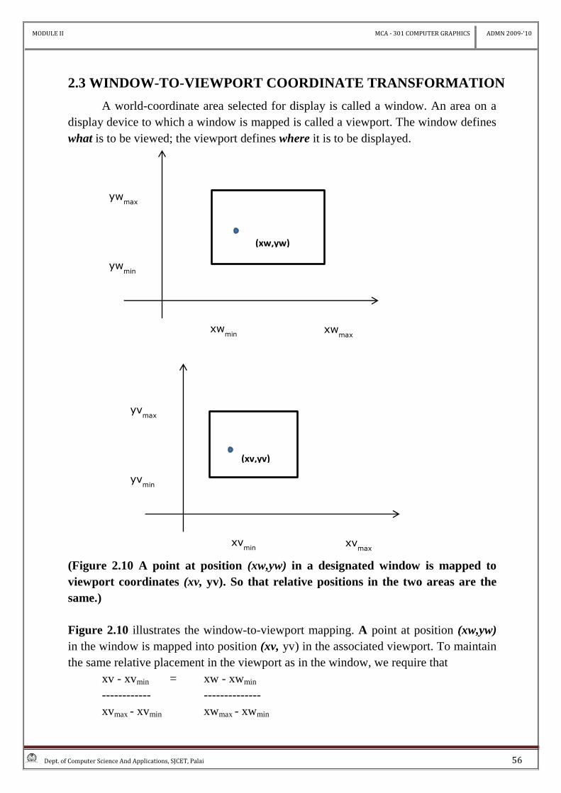
A world-coordinate area selected for display is called a window. An area on a
display device to which a window is mapped is called a viewport. The window defines
what is to be viewed; the viewport defines where it is to be displayed.
(Figure 2.10 A point at position (xw,yw) in a designated window is mapped to
viewport coordinates (xv, yv). So that relative positions in the two areas are the
same.)
Figure 2.10 illustrates the window-to-viewport mapping. A point at position (xw,yw)
in the window is mapped into position (xv, yv) in the associated viewport. To maintain
the same relative placement in the viewport as in the window, we require that
xv - xvmin = xw - xwmin
------------ --------------
xvmax - xvmin xwmax - xwmin
ywmin
ywmax
xwmax
xwmin
(xw,yw)
yvmin
yvmax
xvmax
xvmin
(xv,yv)
MODULE II MCA - 301 COMPUTER GRAPHICS ADMN 2009-‘10
Dept. of Computer Science And Applications, SJCET, Palai 57
yv - yvmin = yw - ywmin
------------- --------------
yvmax - yvmin ywmax - ywmin
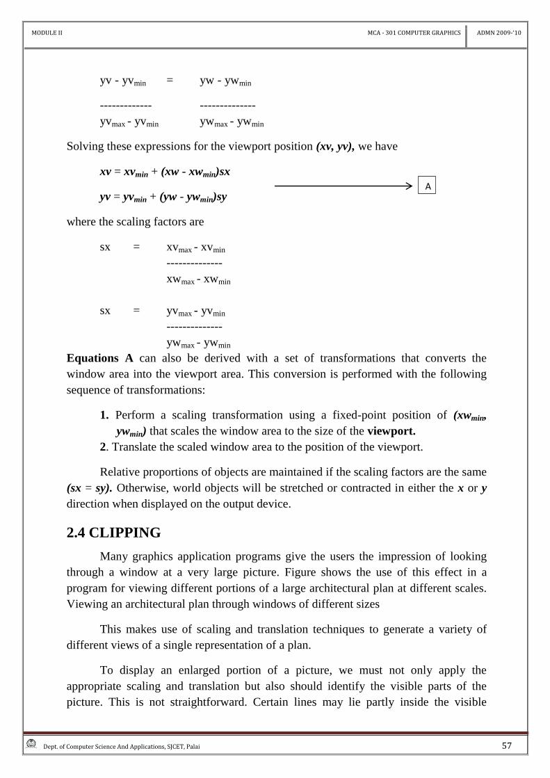
Solving these expressions for the viewport position (xv, yv), we have
xv = xvmin + (xw - xwmin)sx
yv = yvmin + (yw - ywmin)sy
where the scaling factors are
sx = xvmax - xvmin
--------------
xwmax - xwmin
sx = yvmax - yvmin
--------------
ywmax - ywmin
Equations A can also be derived with a set of transformations that converts the
window area into the viewport area. This conversion is performed with the following
sequence of transformations:
1. Perform a scaling transformation using a fixed-point position of (xwmin,
ywmin) that scales the window area to the size of the viewport.
2. Translate the scaled window area to the position of the viewport.
Relative proportions of objects are maintained if the scaling factors are the same
(sx = sy). Otherwise, world objects will be stretched or contracted in either the x or y
direction when displayed on the output device.
2.4 CLIPPING
Many graphics application programs give the users the impression of looking
through a window at a very large picture. Figure shows the use of this effect in a
program for viewing different portions of a large architectural plan at different scales.
Viewing an architectural plan through windows of different sizes
This makes use of scaling and translation techniques to generate a variety of
different views of a single representation of a plan.
To display an enlarged portion of a picture, we must not only apply the
appropriate scaling and translation but also should identify the visible parts of the
picture. This is not straightforward. Certain lines may lie partly inside the visible
A
MODULE II MCA - 301 COMPUTER GRAPHICS ADMN 2009-‘10
Dept. of Computer Science And Applications, SJCET, Palai 58
portion of the picture and partly outside. We cannot display each of these lines in its
entirety.
Occurrence of wraparound in drawing a partially invisible triangle. The correct
way to select visible information for display is to use clipping, a process which divides
each element of the picture in to its visible and invisible portions, allowing the
invisible portion to be discarded. Clipping can be applied to a variety of different types
of picture elements such as pointer, lines, curves, text character and polygons.
2.4.1 POINT CLlPPlNG
Assuming that the clip window is a rectangle in standard position, we save a
point P = (x, y) for display if the following inequalities are satisfied:
xwmin≤x≤xwmax
ywmin≤y≤ywmax
Where the edges of the clip window (xwmin, xwmax, ywmin , ywmax) can be either
the world-coordinate window boundaries or viewport boundaries. If any one of these
four inequalities is not satisfied, the point is clipped (not saved for display).
Although point clipping is applied less often than line or polygon clipping,
some applications may require a point clipping procedure. For example, point clipping
can be applied to scenes involving explosions or sea foam that are modeled with
particles (points) distributed in some region of the scene.
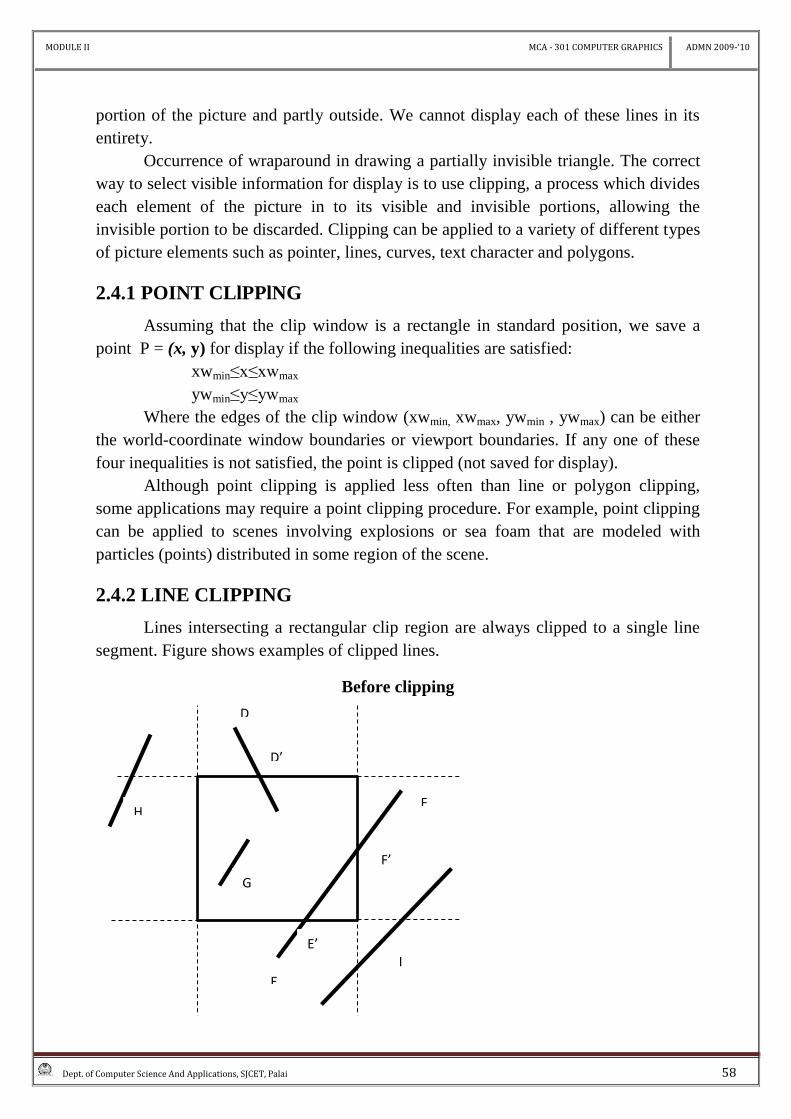
2.4.2 LINE CLIPPING
Lines intersecting a rectangular clip region are always clipped to a single line
segment. Figure shows examples of clipped lines.
Before clipping
D
D’
F
F’
E
E’
G
H
I
MODULE II MCA - 301 COMPUTER GRAPHICS ADMN 2009-‘10
Dept. of Computer Science And Applications, SJCET, Palai 59
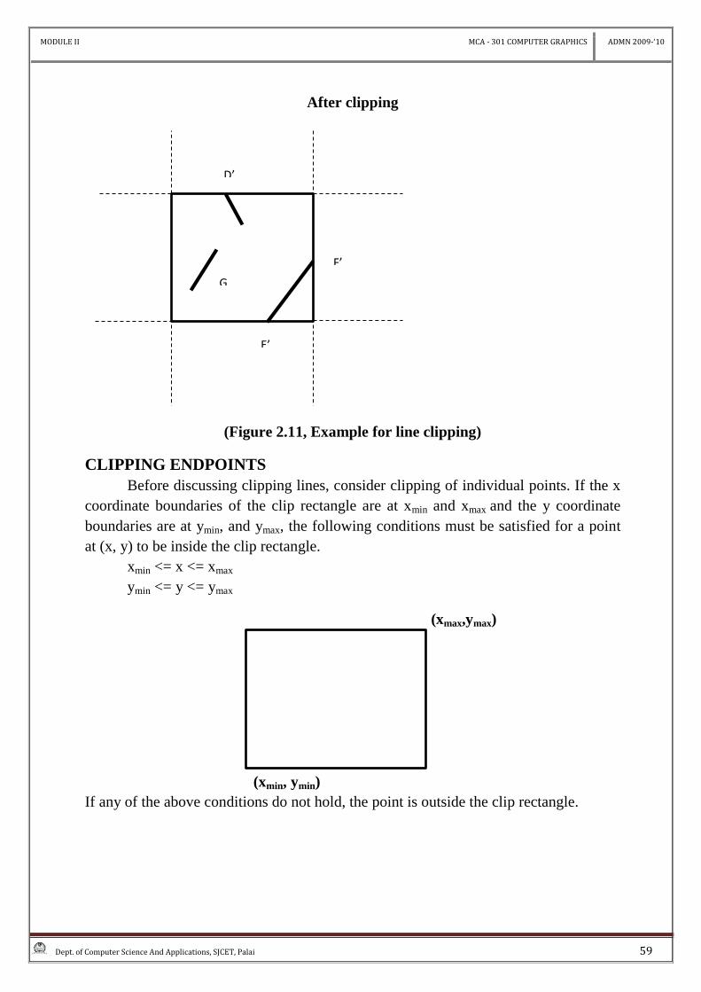
After clipping
(Figure 2.11, Example for line clipping)
CLIPPING ENDPOINTS
Before discussing clipping lines, consider clipping of individual points. If the x
coordinate boundaries of the clip rectangle are at xmin and xmax and the y coordinate
boundaries are at ymin, and ymax, the following conditions must be satisfied for a point
at (x, y) to be inside the clip rectangle.
xmin <= x <= xmax
ymin <= y <= ymax
(xmax,ymax)
(xmin, ymin)
If any of the above conditions do not hold, the point is outside the clip rectangle.
D’
F’
E’
G
MODULE II MCA - 301 COMPUTER GRAPHICS ADMN 2009-‘10
Dept. of Computer Science And Applications, SJCET, Palai 60
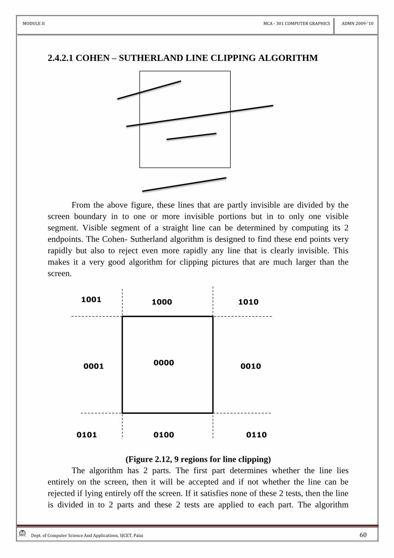
2.4.2.1 COHEN – SUTHERLAND LINE CLIPPING ALGORITHM
From the above figure, these lines that are partly invisible are divided by the
screen boundary in to one or more invisible portions but in to only one visible
segment. Visible segment of a straight line can be determined by computing its 2
endpoints. The Cohen- Sutherland algorithm is designed to find these end points very
rapidly but also to reject even more rapidly any line that is clearly invisible. This
makes it a very good algorithm for clipping pictures that are much larger than the
screen.
(Figure 2.12, 9 regions for line clipping)
The algorithm has 2 parts. The first part determines whether the line lies
entirely on the screen, then it will be accepted and if not whether the line can be
rejected if lying entirely off the screen. If it satisfies none of these 2 tests, then the line
is divided in to 2 parts and these 2 tests are applied to each part. The algorithm
0001 0010
1000
0101 0100 0110
1010 1001
0000
MODULE II MCA - 301 COMPUTER GRAPHICS ADMN 2009-‘10
Dept. of Computer Science And Applications, SJCET, Palai 61
depends on the fact that every line is entirely on the screen. Or can be divided so that
one part can be rejected.
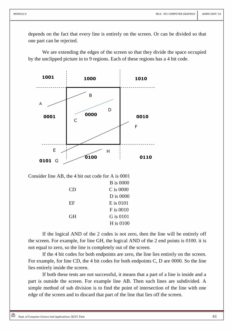
We are extending the edges of the screen so that they divide the space occupied
by the unclipped picture in to 9 regions. Each of these regions has a 4 bit code.
Consider line AB, the 4 bit out code for A is 0001
B is 0000
CD C is 0000
D is 0000
EF E is 0101
F is 0010
GH G is 0101
H is 0100
If the logical AND of the 2 codes is not zero, then the line will be entirely off
the screen. For example, for line GH, the logical AND of the 2 end points is 0100. it is
not equal to zero, so the line is completely out of the screen.
If the 4 bit codes for both endpoints are zero, the line lies entirely on the screen.
For example, for line CD, the 4 bit codes for both endpoints C, D are 0000. So the line
lies entirely inside the screen.
If both these tests are not successful, it means that a part of a line is inside and a
part is outside the screen. For example line AB. Then such lines are subdivided. A
simple method of sub division is to find the point of intersection of the line with one
edge of the screen and to discard that part of the line that lies off the screen.
0001 0010
1000
0101 0100 0110
1010 1001
0000
A
B
C
D
E
F
G
H
MODULE II MCA - 301 COMPUTER GRAPHICS ADMN 2009-‘10
Dept. of Computer Science And Applications, SJCET, Palai 62
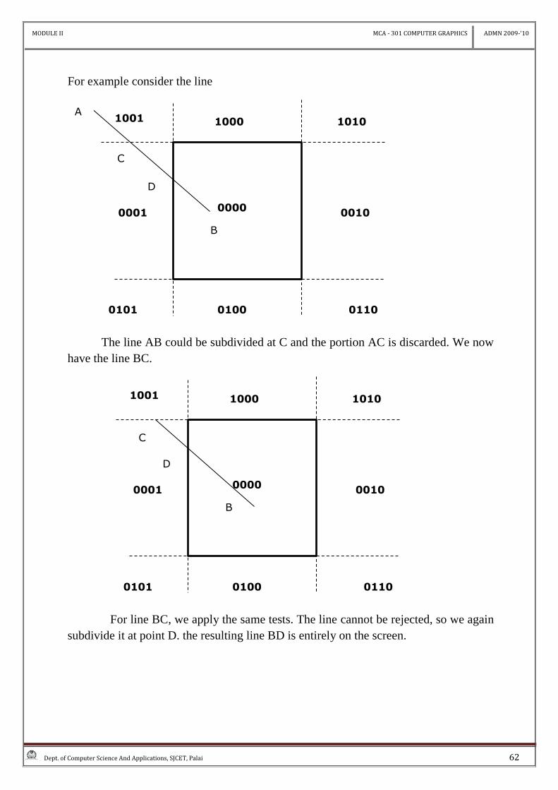
For example consider the line
The line AB could be subdivided at C and the portion AC is discarded. We now
have the line BC.
For line BC, we apply the same tests. The line cannot be rejected, so we again
subdivide it at point D. the resulting line BD is entirely on the screen.
0001 0010
1000
0101 0100 0110
1010 1001
0000
D
B
0001 0010
1000
0101 0100 0110
1010 1001
0000
D
B
C
A
C
MODULE II MCA - 301 COMPUTER GRAPHICS ADMN 2009-‘10
Dept. of Computer Science And Applications, SJCET, Palai 63
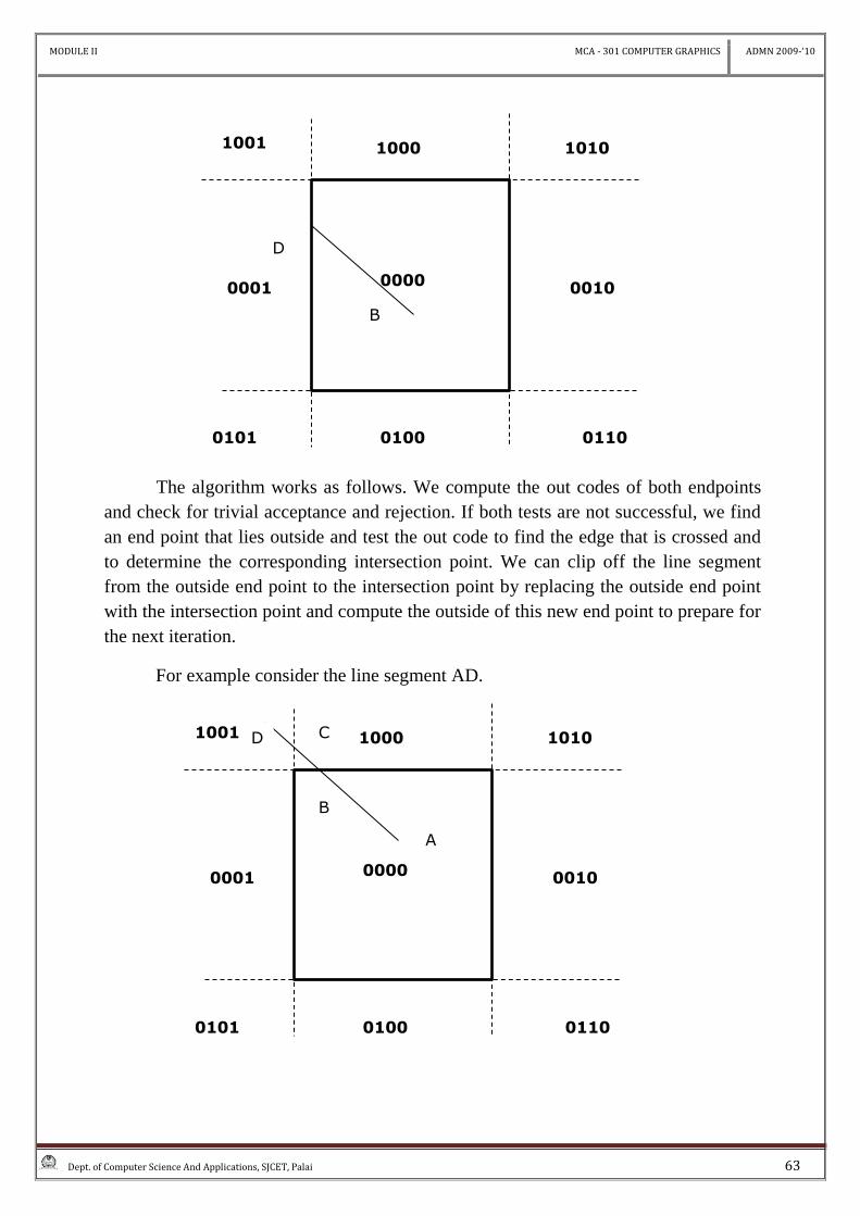
The algorithm works as follows. We compute the out codes of both endpoints
and check for trivial acceptance and rejection. If both tests are not successful, we find
an end point that lies outside and test the out code to find the edge that is crossed and
to determine the corresponding intersection point. We can clip off the line segment
from the outside end point to the intersection point by replacing the outside end point
with the intersection point and compute the outside of this new end point to prepare for
the next iteration.
For example consider the line segment AD.
0001 0010
1000
0101 0100 0110
1010 1001
0000
D
B
0001 0010
1000
0101 0100 0110
1010 1001
0000
B
A
D C
MODULE II MCA - 301 COMPUTER GRAPHICS ADMN 2009-‘10
Dept. of Computer Science And Applications, SJCET, Palai 64
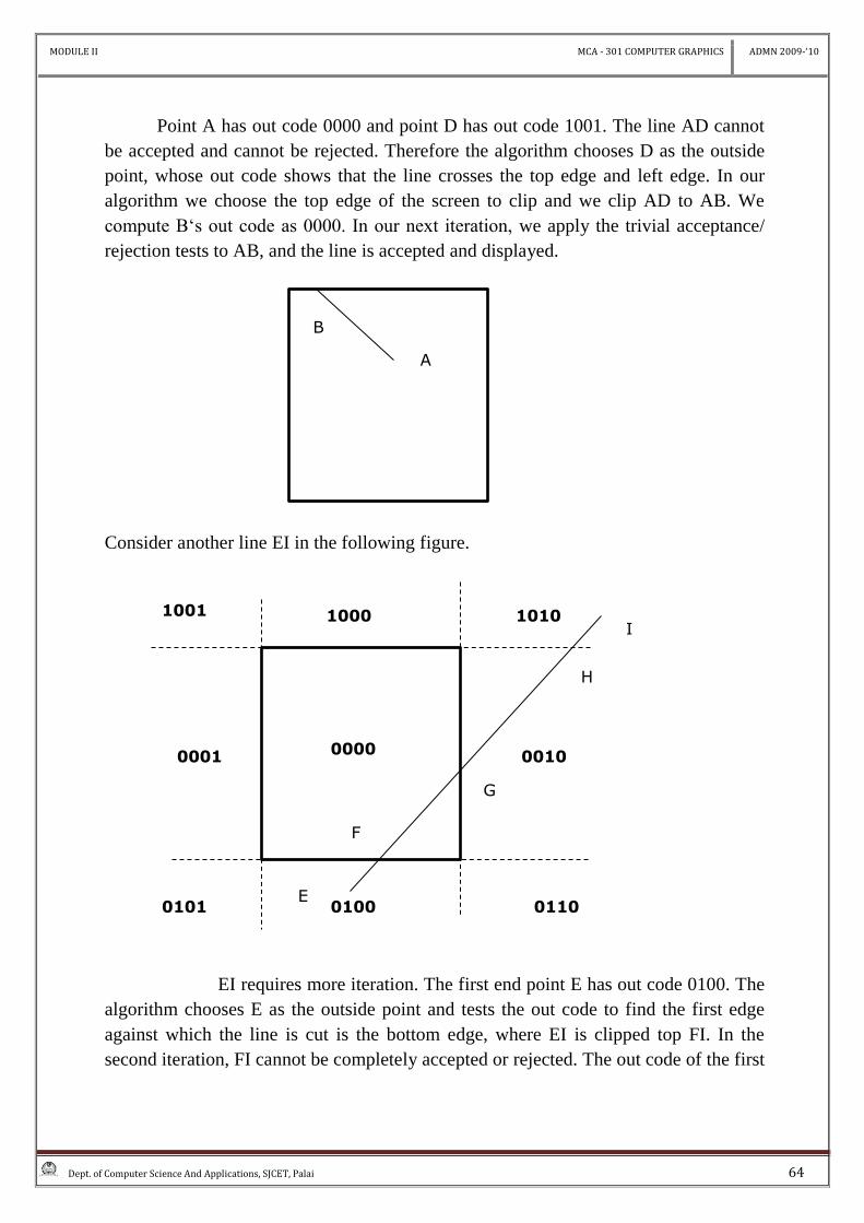
Point A has out code 0000 and point D has out code 1001. The line AD cannot
be accepted and cannot be rejected. Therefore the algorithm chooses D as the outside
point, whose out code shows that the line crosses the top edge and left edge. In our
algorithm we choose the top edge of the screen to clip and we clip AD to AB. We
compute B‘s out code as 0000. In our next iteration, we apply the trivial acceptance/
rejection tests to AB, and the line is accepted and displayed.
Consider another line EI in the following figure.
EI requires more iteration. The first end point E has out code 0100. The
algorithm chooses E as the outside point and tests the out code to find the first edge
against which the line is cut is the bottom edge, where EI is clipped top FI. In the
second iteration, FI cannot be completely accepted or rejected. The out code of the first
B
A
0001 0010
1000
0101 0100 0110
1010 1001
0000
H
I
G
E
F
MODULE II MCA - 301 COMPUTER GRAPHICS ADMN 2009-‘10
Dept. of Computer Science And Applications, SJCET, Palai 65
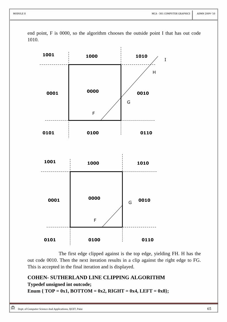
end point, F is 0000, so the algorithm chooses the outside point I that has out code
1010.
The first edge clipped against is the top edge, yielding FH. H has the
out code 0010. Then the next iteration results in a clip against the right edge to FG.
This is accepted in the final iteration and is displayed.
COHEN- SUTHERLAND LINE CLIPPING ALGORITHM
Typedef unsigned int outcode;
Enum { TOP = 0x1, BOTTOM = 0x2, RIGHT = 0x4, LEFT = 0x8};
0001 0010
1000
0101 0100 0110
1010 1001
0000
H
I
G
F
0001 0010
1000
0101 0100 0110
1010 1001
0000 G
F
MODULE II MCA - 301 COMPUTER GRAPHICS ADMN 2009-‘10
Dept. of Computer Science And Applications, SJCET, Palai 66
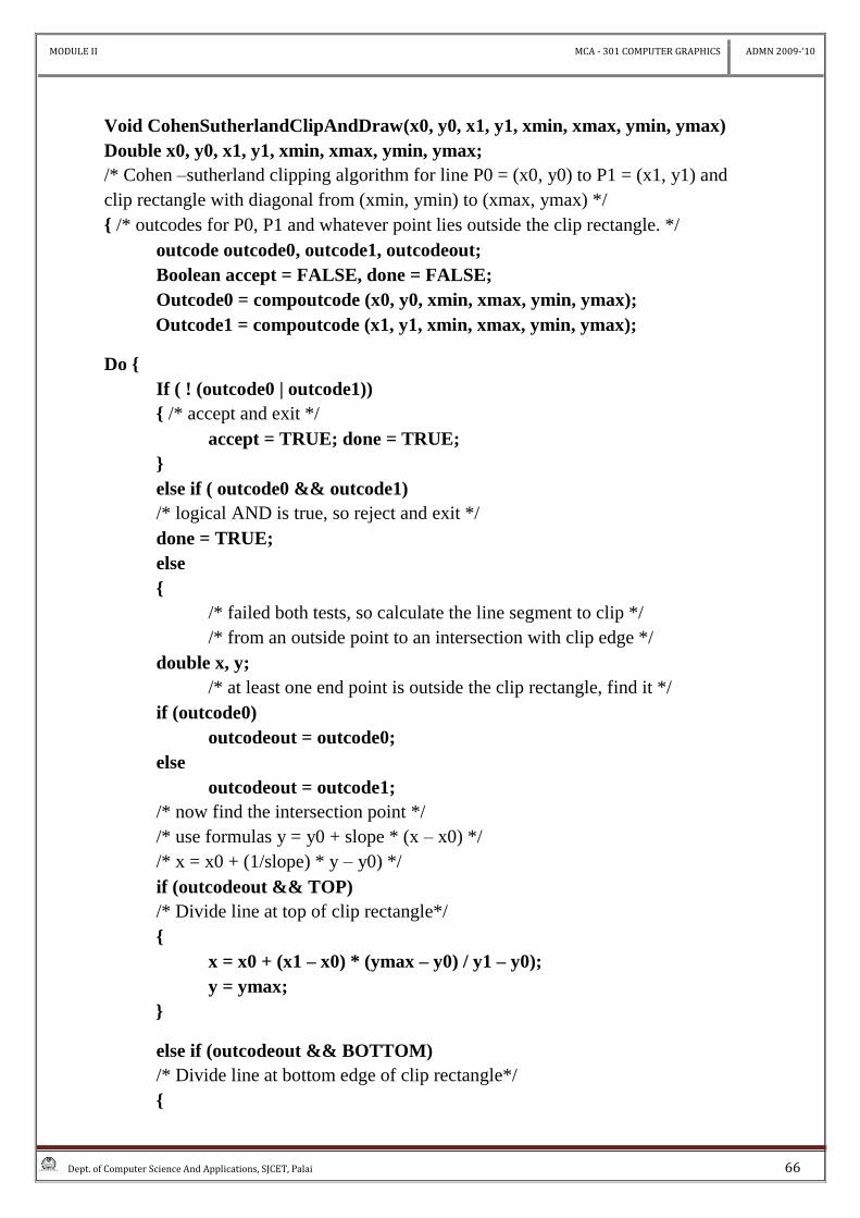
Void CohenSutherlandClipAndDraw(x0, y0, x1, y1, xmin, xmax, ymin, ymax)
Double x0, y0, x1, y1, xmin, xmax, ymin, ymax;
/* Cohen –sutherland clipping algorithm for line P0 = (x0, y0) to P1 = (x1, y1) and
clip rectangle with diagonal from (xmin, ymin) to (xmax, ymax) */
{ /* outcodes for P0, P1 and whatever point lies outside the clip rectangle. */
outcode outcode0, outcode1, outcodeout;
Boolean accept = FALSE, done = FALSE;
Outcode0 = compoutcode (x0, y0, xmin, xmax, ymin, ymax);
Outcode1 = compoutcode (x1, y1, xmin, xmax, ymin, ymax);
Do {
If ( ! (outcode0 | outcode1))
{ /* accept and exit */
accept = TRUE; done = TRUE;
}
else if ( outcode0 && outcode1)
/* logical AND is true, so reject and exit */
done = TRUE;
else
{
/* failed both tests, so calculate the line segment to clip */
/* from an outside point to an intersection with clip edge */
double x, y;
/* at least one end point is outside the clip rectangle, find it */
if (outcode0)
outcodeout = outcode0;
else
outcodeout = outcode1;
/* now find the intersection point */
/* use formulas y = y0 + slope * (x – x0) */
/* x = x0 + (1/slope) * y – y0) */
if (outcodeout && TOP)
/* Divide line at top of clip rectangle*/
{
x = x0 + (x1 – x0) * (ymax – y0) / y1 – y0);
y = ymax;
}
else if (outcodeout && BOTTOM)
/* Divide line at bottom edge of clip rectangle*/
{
MODULE II MCA - 301 COMPUTER GRAPHICS ADMN 2009-‘10
Dept. of Computer Science And Applications, SJCET, Palai 67
x = x0 + (x1 – x0) * (ymin – y0) / y1 – y0);
y = ymin;
}
else if (outcodeout && RIGHT)
/* Divide line at right edge of clip rectangle*/
{
y = y0 + (y1 – y0) * (xmax – x0) / x1 – x0);
x = xmax;
}
else
/* Divide line at left edge of clip rectangle*/
{
y = y0 + (y1 – y0) * (xmin – x0) / x1 – x0);
x = xmin;
}
/* now we move outside point to intersection point to clip */
/* and get ready for next pass */
if (oucodeout == outcode0)
{
x0 = x; y0 = y;
outcode0 = compoutcode (x0, y0, xmin, xmax, ymin, ymax);
}
else
{
x1 = x; y1 = y;
outcode1 = compoutcode (x1, y1, xmin, xmax, ymin, ymax);
}
}
}while (done == FALSE);
if (accept)
drawline ( x0, y0, x1, y1);
}
outcode compoutcode ( x, y, xmin, xmax, ymin, ymax)
double x, y, xmin, xmax, ymin, ymax;
{
outcode code = 0;
if (y > ymax)
code = code || TOP;
else if (y < ymin)
MODULE II MCA - 301 COMPUTER GRAPHICS ADMN 2009-‘10
Dept. of Computer Science And Applications, SJCET, Palai 68
code = code || BOTTOM;
if (x > xmax)
code = code || RIGHT;
else if (x < xmin)
code = code || LEFT; return code;
}
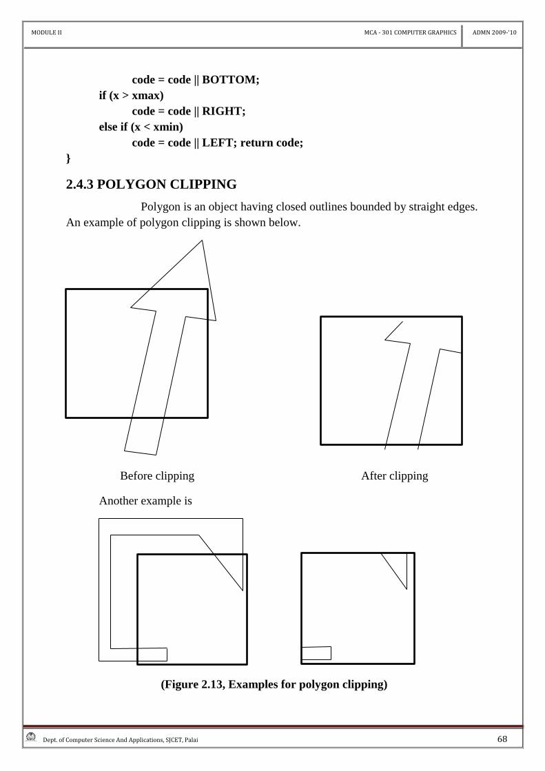
2.4.3 POLYGON CLIPPING
Polygon is an object having closed outlines bounded by straight edges.
An example of polygon clipping is shown below.
Before clipping After clipping
Another example is
(Figure 2.13, Examples for polygon clipping)
MODULE II MCA - 301 COMPUTER GRAPHICS ADMN 2009-‘10
Dept. of Computer Science And Applications, SJCET, Palai 69
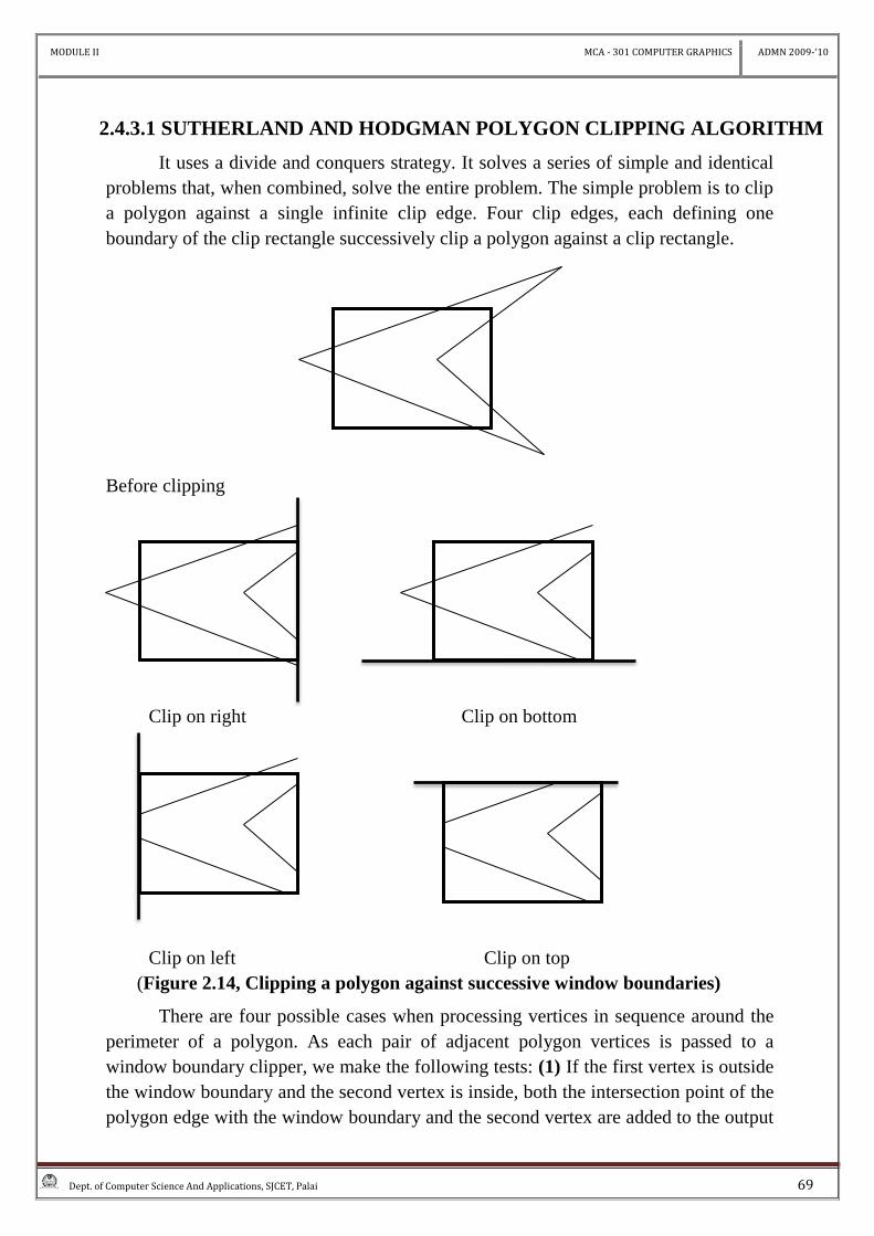
2.4.3.1 SUTHERLAND AND HODGMAN POLYGON CLIPPING ALGORITHM
It uses a divide and conquers strategy. It solves a series of simple and identical
problems that, when combined, solve the entire problem. The simple problem is to clip
a polygon against a single infinite clip edge. Four clip edges, each defining one
boundary of the clip rectangle successively clip a polygon against a clip rectangle.
Before clipping
Clip on right Clip on bottom
Clip on left Clip on top
(Figure 2.14, Clipping a polygon against successive window boundaries)
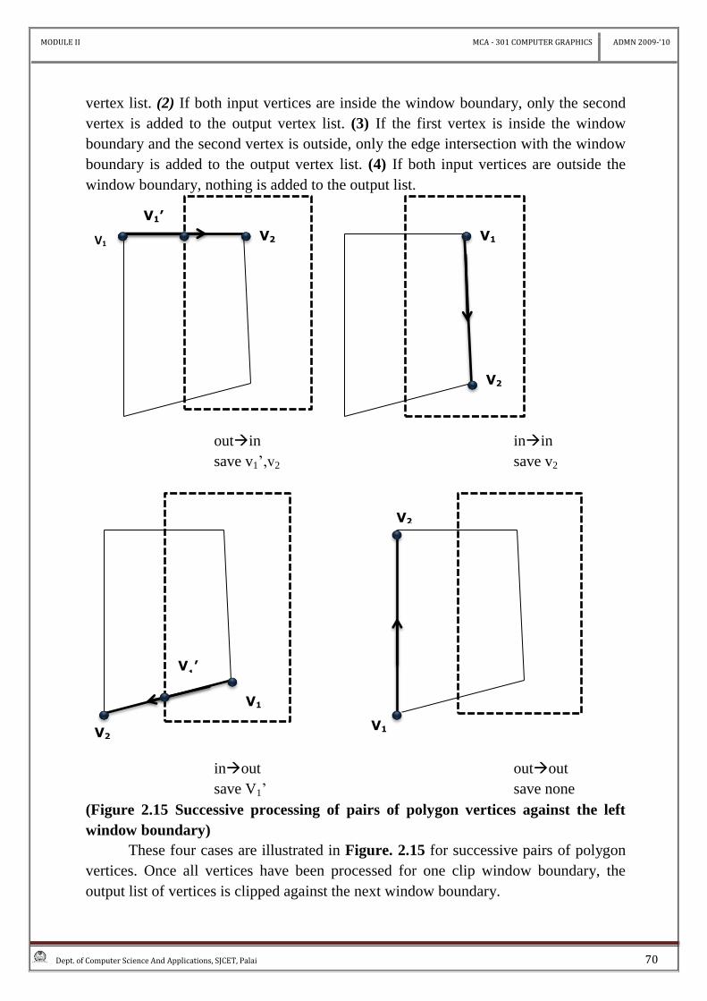
There are four possible cases when processing vertices in sequence around the
perimeter of a polygon. As each pair of adjacent polygon vertices is passed to a
window boundary clipper, we make the following tests: (1) If the first vertex is outside
the window boundary and the second vertex is inside, both the intersection point of the
polygon edge with the window boundary and the second vertex are added to the output
MODULE II MCA - 301 COMPUTER GRAPHICS ADMN 2009-‘10
Dept. of Computer Science And Applications, SJCET, Palai 70
vertex list. (2) If both input vertices are inside the window boundary, only the second
vertex is added to the output vertex list. (3) If the first vertex is inside the window
boundary and the second vertex is outside, only the edge intersection with the window
boundary is added to the output vertex list. (4) If both input vertices are outside the
window boundary, nothing is added to the output list.
outin inin
save v1’,v2 save v2
inout outout
save V1’ save none
(Figure 2.15 Successive processing of pairs of polygon vertices against the left
window boundary)
These four cases are illustrated in Figure. 2.15 for successive pairs of polygon
vertices. Once all vertices have been processed for one clip window boundary, the
output list of vertices is clipped against the next window boundary.
V1
V1’
V2
V2
V1
V2
V1
V1’
V2
V1
MODULE II MCA - 301 COMPUTER GRAPHICS ADMN 2009-‘10
Dept. of Computer Science And Applications, SJCET, Palai 71
SUTHERLAND-HODGMAN POLYGON CLIPPING ALGORITHM
Typedef point vertex; /*point holds double x, y*/
Typedef vertex edge [2];
Typedef vertex vertexarray [MAX];
Static void output (vertex, int *, vertexarray);
Static boolean inside (vertex, edge);
Static vertex intersect (vertex, vertex, edge);
Void SutherlandHodgmanPolygonClip (
Vertexarray invertexarray, /*input vertex array */
Vertexarray outvertexarray, /*output vertex array */
Int inlength, /* no. of entries in invertexarray*/
Int outlength, /* no. of entries in outvertexarray */
Edge clipboundary) /* edge of clip polygon */
{
vertex s, p; /* start, end point of current polygon edge */
vertex I; /* intersection point with clip boundary */
int j; /* vertex loop counter */
*outlength = 0; /* start with the last vertex in invertexarray*/
s = invertexarray [inlength –1];
for (j = 0; j < inlength; j++)
{
p = invertexarray [ j ];
if (inside (p, clipboundary)) /* cases 1 and 4 */
{
if ( inside (s,clipboundary)) /* case 1 */
output (p, outlength, outvertexarray);
}
else
{ /* case 4 */
i = intersect (s, p, clipboundary);
Output (i, outlength, outvertexarray);
Output (p, outlength, outvertexarray);
}
}
else /* case 2 and 3 */
if ( inside ( s, clipboundary)) /* case 2 */
{
i = intersect ( s, p, clipboundary);
Output (i, outlength, outvertexarray);
} /* no action for case 3 */
MODULE II MCA - 301 COMPUTER GRAPHICS ADMN 2009-‘10
Dept. of Computer Science And Applications, SJCET, Palai 72
s = p; /* advance to next pair of vertices */
} /* end of for */
}
/* adds newvertex to outvertexarray and then updates outlength */
static void output (
vertex newvertex, int *outlength, vertexarray outvertexarray)
{
---
---
---
}
/*checks whether the vertex lies inside the clip edge or not */
static Boolean inside ( vertex testvertex, edge clipboundary)
{
---
---
}
/*Clips polygon edge (first, second) against clipboundary, outputs the new point
*/
static vertex intersect (vertex first, vertex second, edge clipboundary)
{
---
---
---
}
The function SutherlandHodgmanPolygonClip() accepts an array invertexarray
of vertices and creates another array outvertexarray of vertices. The function output ()
places a vertex in to outvertexarray.
The function intersect () calculates the intersection of the polygon edge from
vertex s to vertex p with clip boundary. The function inside () returns true if the vertex
is on the inside of the clip boundary.
2.4.4CURVE CLIPPING
The bounding rectangle for a circle or other curved object can be used first to
test for overlap with a rectangular clip window. If the bounding rectangle for the object
is completely inside the window, we save the object. If the rectangle is determined to
be completely outside the window, we discard the object. In either case, there is no
further computation necessary. But if the bounding rectangle test fails, we can look for
other computation-saving approaches. For a circle, we can use the coordinate extents
MODULE II MCA - 301 COMPUTER GRAPHICS ADMN 2009-‘10
Dept. of Computer Science And Applications, SJCET, Palai 73
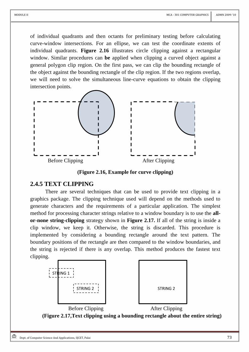
of individual quadrants and then octants for preliminary testing before calculating
curve-window intersections. For an ellipse, we can test the coordinate extents of
individual quadrants. Figure 2.16 illustrates circle clipping against a rectangular
window. Similar procedures can be applied when clipping a curved object against a
general polygon clip region. On the first pass, we can clip the bounding rectangle of
the object against the bounding rectangle of the clip region. If the two regions overlap,
we will need to solve the simultaneous line-curve equations to obtain the clipping
intersection points.
Before Clipping After Clipping
(Figure 2.16, Example for curve clipping)
2.4.5 TEXT CLIPPING
There are several techniques that can be used to provide text clipping in a
graphics package. The clipping technique used will depend on the methods used to
generate characters and the requirements of a particular application. The simplest
method for processing character strings relative to a window boundary is to use the all-
or-none string-clipping strategy shown in Figure 2.17. If all of the string is inside a
clip window, we keep it. Otherwise, the string is discarded. This procedure is
implemented by considering a bounding rectangle around the text pattern. The
boundary positions of the rectangle are then compared to the window boundaries, and
the string is rejected if there is any overlap. This method produces the fastest text
clipping.
Before Clipping After Clipping
(Figure 2.17,Text clipping using a bounding rectangle about the entire string)
STRING 1
STRING 2 STRING 2
MODULE II MCA - 301 COMPUTER GRAPHICS ADMN 2009-‘10
Dept. of Computer Science And Applications, SJCET, Palai 74
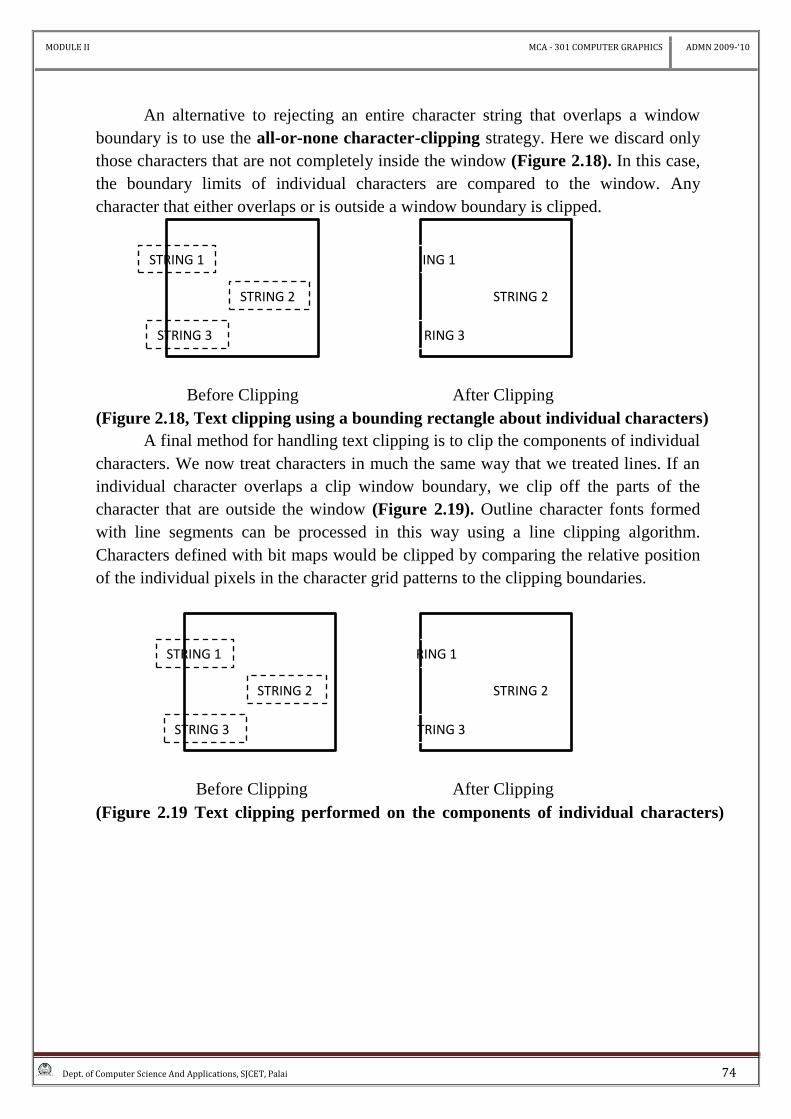
An alternative to rejecting an entire character string that overlaps a window
boundary is to use the all-or-none character-clipping strategy. Here we discard only
those characters that are not completely inside the window (Figure 2.18). In this case,
the boundary limits of individual characters are compared to the window. Any
character that either overlaps or is outside a window boundary is clipped.
Before Clipping After Clipping
(Figure 2.18, Text clipping using a bounding rectangle about individual characters)
A final method for handling text clipping is to clip the components of individual
characters. We now treat characters in much the same way that we treated lines. If an
individual character overlaps a clip window boundary, we clip off the parts of the
character that are outside the window (Figure 2.19). Outline character fonts formed
with line segments can be processed in this way using a line clipping algorithm.
Characters defined with bit maps would be clipped by comparing the relative position
of the individual pixels in the character grid patterns to the clipping boundaries.
Before Clipping After Clipping
(Figure 2.19 Text clipping performed on the components of individual characters)
STRING 1
STRING 2
STRING 3
ING 1
STRING 2
RING 3
STRING 1
STRING 2
STRING 3
RING 1
STRING 2
TRING 3