2/24/04© University of Wisconsin, CS559 Spring 2004 Last Time 3D Transformations –Most are...
37
2/24/04 © University of Wisconsin, CS559 S pring 2004 Last Time • 3D Transformations – Most are natural extensions of 2D transforms – Rotations can be represented in many ways: Orthonormal 3x3 sub-matrix, Quaternions, Axis-Angle, Exponential Map, Euler Angles • Coordinate Systems – Local/Object, Global/World, Eye/View/Camera, Canonical View, Window/Screen • Canonical to Window mappings • Orthogonal projection when the camera axes are aligned with the world axes
-
Upload
debra-mccarthy -
Category
Documents
-
view
215 -
download
2
Transcript of 2/24/04© University of Wisconsin, CS559 Spring 2004 Last Time 3D Transformations –Most are...
2/24/04 © University of Wisconsin, CS559 Spring 2004
Last Time
• 3D Transformations– Most are natural extensions of 2D transforms
– Rotations can be represented in many ways: Orthonormal 3x3 sub-matrix, Quaternions, Axis-Angle, Exponential Map, Euler Angles
• Coordinate Systems– Local/Object, Global/World, Eye/View/Camera, Canonical View,
Window/Screen
• Canonical to Window mappings
• Orthogonal projection when the camera axes are aligned with the world axes
2/24/04 © University of Wisconsin, CS559 Spring 2004
Today
• General Orthogonal viewing
• Perspective viewing
2/24/04 © University of Wisconsin, CS559 Spring 2004
Simple Orthographic Projection
z
y
x
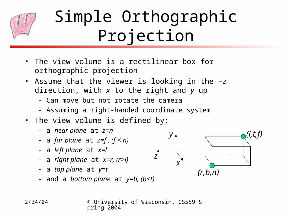
• The view volume is a rectilinear box for orthographic projection
• Assume that the viewer is looking in the –z direction, with x to the right and y up– Can move but not rotate the camera
– Assuming a right-handed coordinate system
• The view volume is defined by:– a near plane at z=n
– a far plane at z=f , (f < n)
– a left plane at x=l
– a right plane at x=r, (r>l)
– a top plane at y=t
– and a bottom plane at y=b, (b<t)(r,b,n)
(l,t,f)
2/24/04 © University of Wisconsin, CS559 Spring 2004
Rendering the Volume
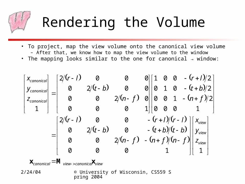
• To project, map the view volume onto the canonical view volume– After that, we know how to map the view volume to the window
• The mapping looks similar to the one for canonical → window:
viewcanonicalviewcanonical
view
view
view
canonical
canonical
canonical
z
y
x
fnfnfn
btbtbt
lrlrlr
fn
bt
lr
fn
bt
lr
z
y
x
xMx
11000
200
020
002
1000
2100
2010
2001
1000
0200
0020
0002
1
2/24/04 © University of Wisconsin, CS559 Spring 2004
General Orthographic Projection
• We could look at the world from any direction, not just along –z
• The image could rotated in any way about the viewing direction: x need not be right, and y need not be up
• How can we specify the view under these circumstances?
2/24/04 © University of Wisconsin, CS559 Spring 2004
Specifying a View
• The location of the eye in space– A point in space for the center of projection, (ex,ey,ez)
• The direction in which we are looking: gaze direction– Specified as a vector: (gx,gy,gz)
– This vector will be normal to the image plane
• A direction that we want to appear up in the image– (upx,upy,upz), This vector does not have to be perpendicular to n
• We also need the size of the view volume – l,r,t,b,n,f– Specified with respect to the eye and image plane, not the world
2/24/04 © University of Wisconsin, CS559 Spring 2004
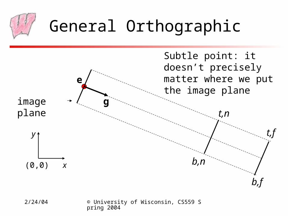
General Orthographic
(0,0) x
y
e
image plane g
b,n
b,f
t,n
t,f
Subtle point: it doesn’t precisely matter where we put the image plane
2/24/04 © University of Wisconsin, CS559 Spring 2004
Getting there…
• We wish to end up in the “simple” situation, so we need a coordinate system with:– A vector toward the viewer
– One pointing right in the image plane
– One pointing up in the image plane
– The origin at the eye
• We must:– Define such a coordinate system, view space
– Transform points from the world space into view space
– Apply our simple projection from before
2/24/04 © University of Wisconsin, CS559 Spring 2004
View Space
• Given our camera definition:– Which point is the origin of view space?
– Which direction is the normal to the view plane, w?
– How do we find the right vector, u?
– How do we find the up vector, v?
• Given these points, how do we do the transformation?
2/24/04 © University of Wisconsin, CS559 Spring 2004
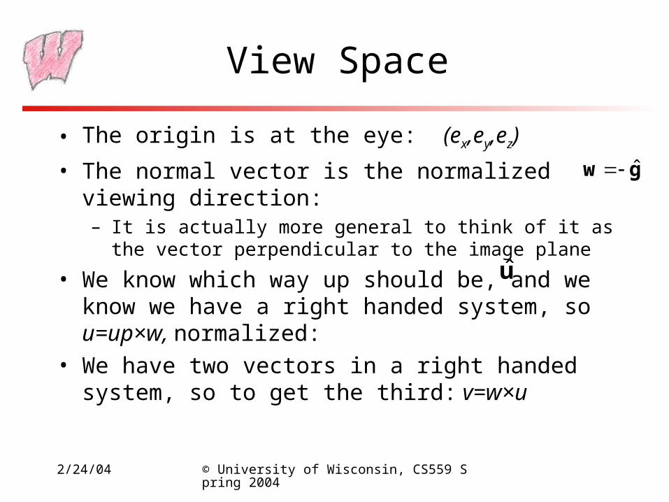
View Space
• The origin is at the eye: (ex,ey,ez)
• The normal vector is the normalized viewing direction:– It is actually more general to think of it as the vector perpendicular
to the image plane
• We know which way up should be, and we know we have a right handed system, so u=up×w, normalized:
• We have two vectors in a right handed system, so to get the third: v=w×u
gw ˆ
u
2/24/04 © University of Wisconsin, CS559 Spring 2004
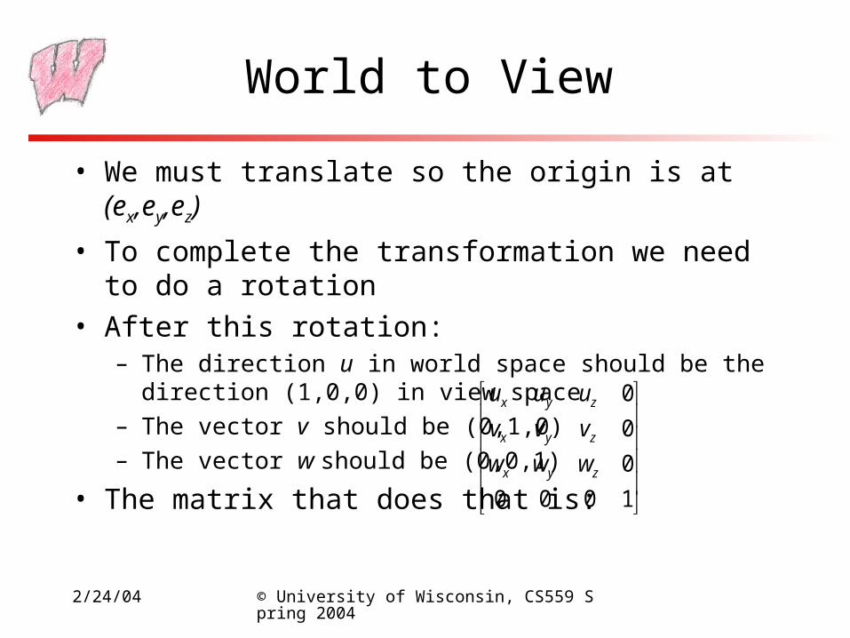
World to View
• We must translate so the origin is at (ex,ey,ez)
• To complete the transformation we need to do a rotation
• After this rotation:– The direction u in world space should be the direction (1,0,0) in
view space
– The vector v should be (0,1,0)
– The vector w should be (0,0,1)
• The matrix that does that is:
1000
0
0
0
zyx
zyx
zyx
www
vvv
uuu
2/24/04 © University of Wisconsin, CS559 Spring 2004
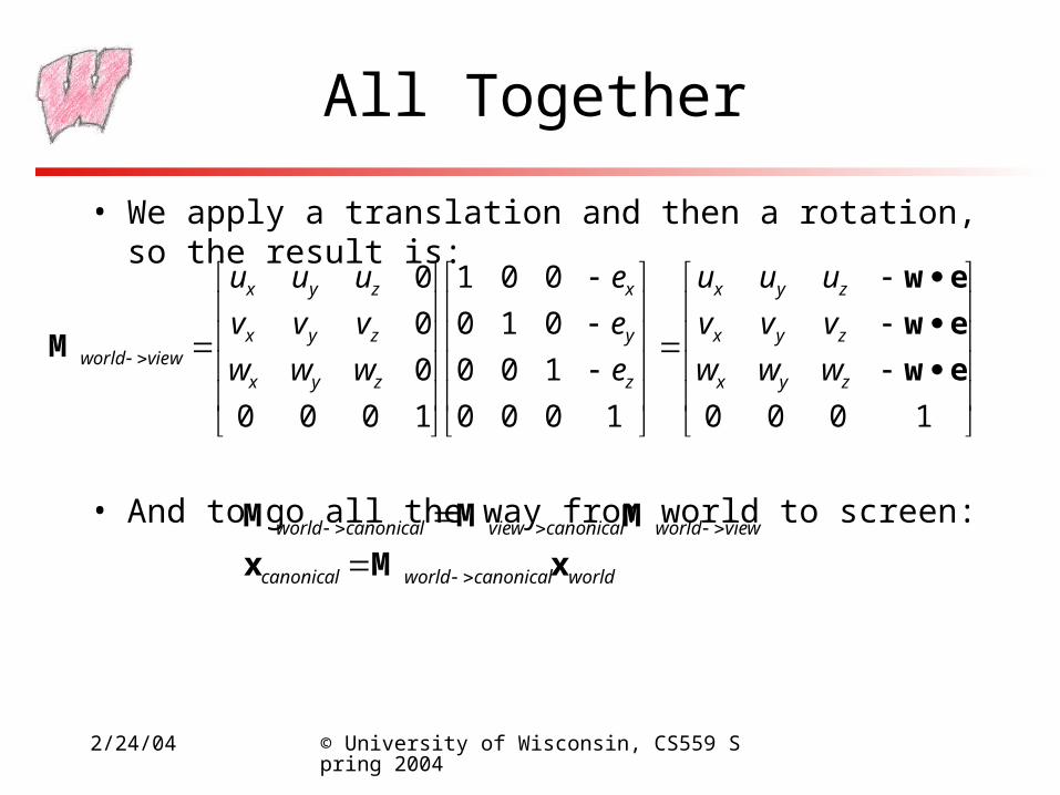
All Together
• We apply a translation and then a rotation, so the result is:
• And to go all the way from world to screen:
10001000
100
010
001
1000
0
0
0
ew
ew
ew
Mzyx
zyx
zyx
z
y
x
zyx
zyx
zyx
viewworld www
vvv
uuu
e
e
e
www
vvv
uuu
worldcanonicalworldcanonical
viewworldcanonicalviewcanonicalworld
xMx
MMM
2/24/04 © University of Wisconsin, CS559 Spring 2004
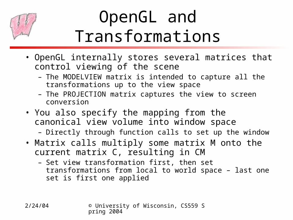
OpenGL and Transformations
• OpenGL internally stores several matrices that control viewing of the scene– The MODELVIEW matrix is intended to capture all the
transformations up to the view space– The PROJECTION matrix captures the view to screen conversion
• You also specify the mapping from the canonical view volume into window space– Directly through function calls to set up the window
• Matrix calls multiply some matrix M onto the current matrix C, resulting in CM– Set view transformation first, then set transformations from local to
world space – last one set is first one applied
2/24/04 © University of Wisconsin, CS559 Spring 2004
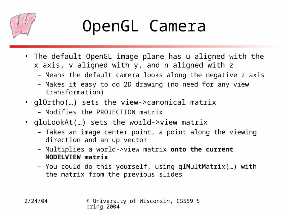
OpenGL Camera
• The default OpenGL image plane has u aligned with the x axis, v aligned with y, and n aligned with z– Means the default camera looks along the negative z axis
– Makes it easy to do 2D drawing (no need for any view transformation)
• glOrtho(…) sets the view->canonical matrix– Modifies the PROJECTION matrix
• gluLookAt(…) sets the world->view matrix– Takes an image center point, a point along the viewing direction and an up
vector
– Multiplies a world->view matrix onto the current MODELVIEW matrix
– You could do this yourself, using glMultMatrix(…) with the matrix from the previous slides
2/24/04 © University of Wisconsin, CS559 Spring 2004
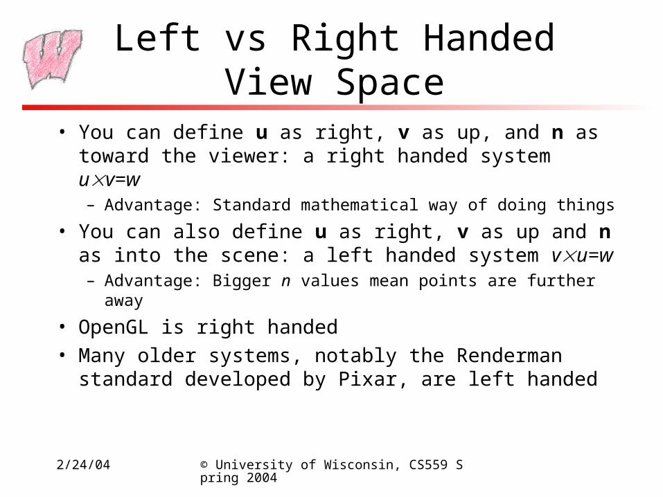
Left vs Right Handed View Space
• You can define u as right, v as up, and n as toward the viewer: a right handed system uv=w– Advantage: Standard mathematical way of doing things
• You can also define u as right, v as up and n as into the scene: a left handed system vu=w– Advantage: Bigger n values mean points are further away
• OpenGL is right handed
• Many older systems, notably the Renderman standard developed by Pixar, are left handed
2/24/04 © University of Wisconsin, CS559 Spring 2004
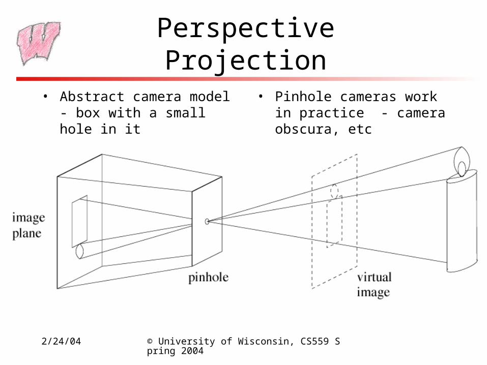
Perspective Projection
• Abstract camera model - box with a small hole in it
• Pinhole cameras work in practice - camera obscura, etc
2/24/04 © University of Wisconsin, CS559 Spring 2004
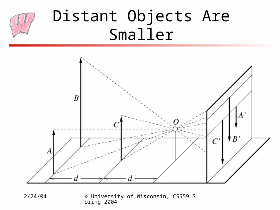
Distant Objects Are Smaller
2/24/04 © University of Wisconsin, CS559 Spring 2004
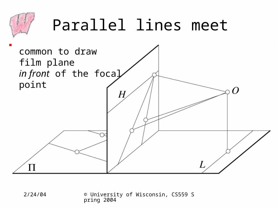
Parallel lines meet
common to draw film planein front of the focal point
2/24/04 © University of Wisconsin, CS559 Spring 2004
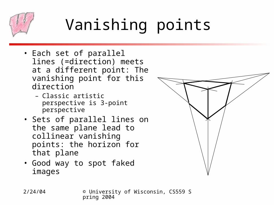
Vanishing points
• Each set of parallel lines (=direction) meets at a different point: The vanishing point for this direction– Classic artistic perspective is 3-
point perspective
• Sets of parallel lines on the same plane lead to collinear vanishing points: the horizon for that plane
• Good way to spot faked images
2/24/04 © University of Wisconsin, CS559 Spring 2004
Basic Perspective Projection
• Assume you have transformed to view space, with x to the right, y up, and z back toward the viewer
• Assume the origin of view space is at the center of projection (the eye)
• Define a focal distance, d, and put the image plane there (note d is negative)
2/24/04 © University of Wisconsin, CS559 Spring 2004
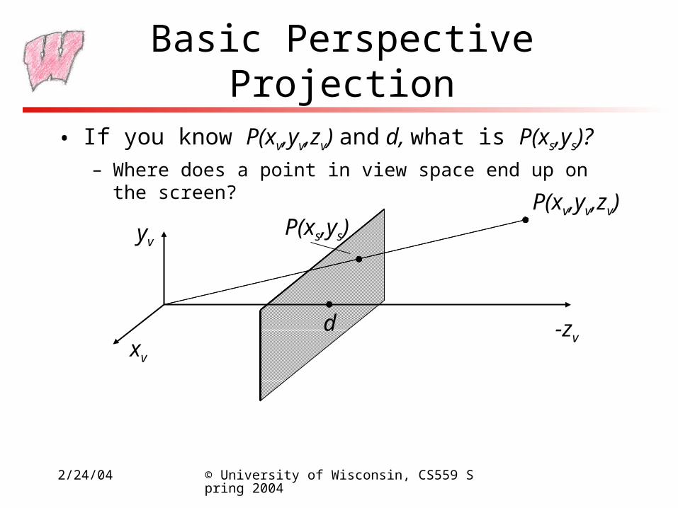
Basic Perspective Projection
• If you know P(xv,yv,zv) and d, what is P(xs,ys)?– Where does a point in view space end up on the screen?
xv
yv
-zvd
P(xv,yv,zv)P(xs,ys)
2/24/04 © University of Wisconsin, CS559 Spring 2004
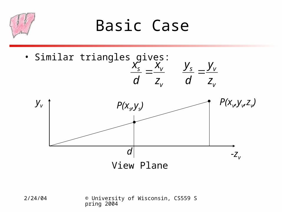
Basic Case
• Similar triangles gives:
v
vs
z
x
d
x
v
vs
z
y
d
y
yv
-zv
P(xv,yv,zv)P(xs,ys)
View Plane
d
2/24/04 © University of Wisconsin, CS559 Spring 2004
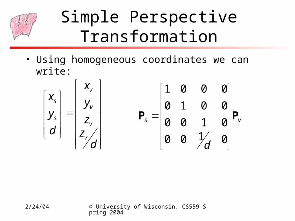
Simple Perspective Transformation
• Using homogeneous coordinates we can write:
dzz
y
x
d
y
x
v
v
v
v
s
s
vs
d
PP
0100
0100
0010
0001
2/24/04 © University of Wisconsin, CS559 Spring 2004
Perspective View Volume
• Recall the orthographic view volume, defined by a near, far, left, right, top and bottom plane
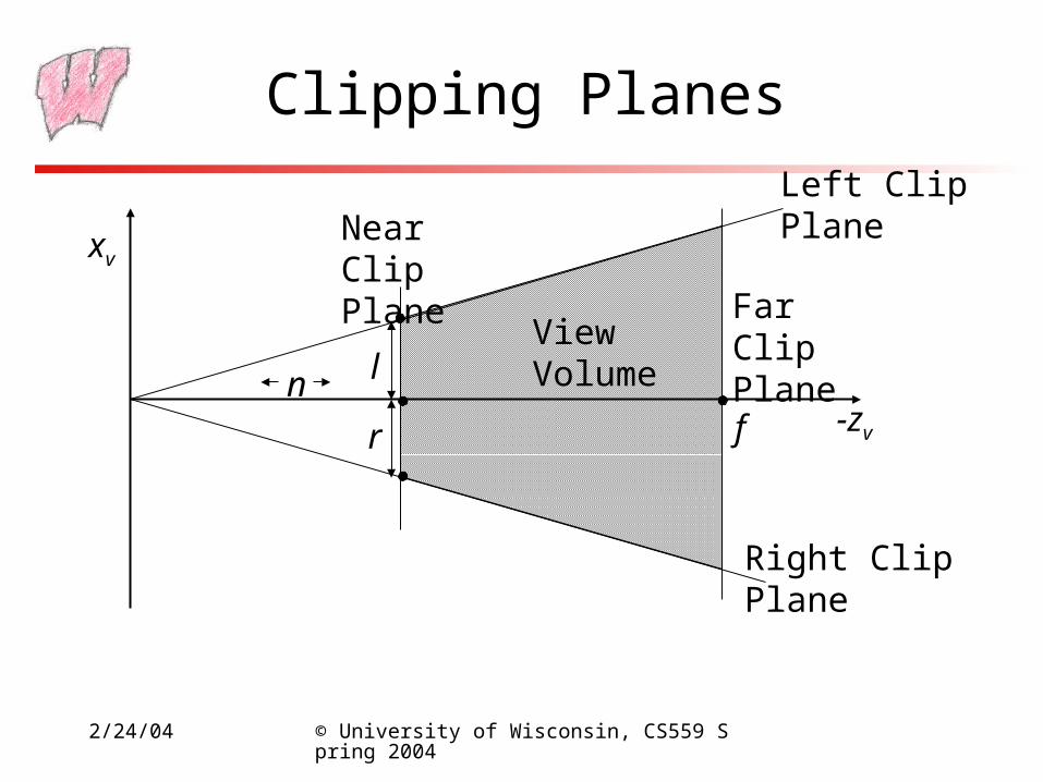
• The perspective view volume is also defined by near, far, left, right, top and bottom planes – the clip planes– Near and far planes are parallel to the image plane: zv=n, zv=f
– Other planes all pass through the center of projection (the origin of view space)
– The left and right planes intersect the image plane in vertical lines
– The top and bottom planes intersect in horizontal lines
2/24/04 © University of Wisconsin, CS559 Spring 2004
Clipping Planes
xv
-zv
Near Clip Plane
Far Clip PlaneView
Volume
Left ClipPlane
Right ClipPlane
fn l
r
2/24/04 © University of Wisconsin, CS559 Spring 2004
Where is the Image Plane?
• Notice that it doesn’t really matter where the image plane is located, once you define the view volume– You can move it forward and backward along the z axis and still get
the same image, only scaled
• But we need to know where it is to define the clipping planes– Assume the left/right/top/bottom planes are defined according to
where they cut the near clip plane
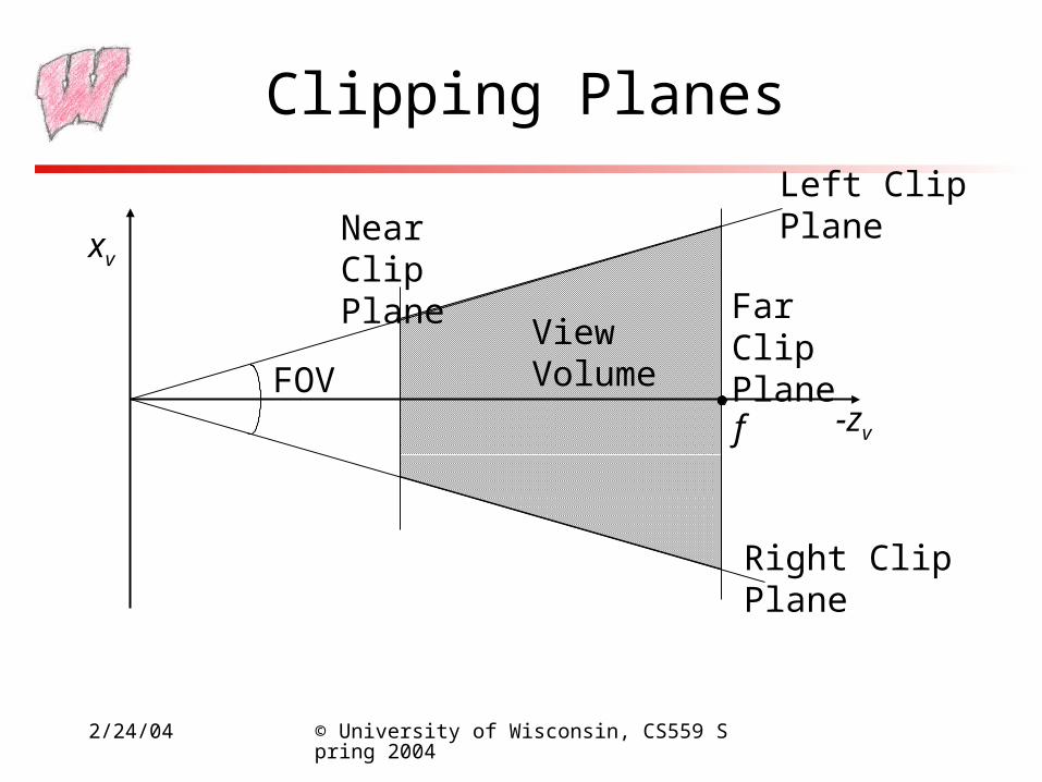
• Or, define the left/right and top/bottom clip planes by the field of view
2/24/04 © University of Wisconsin, CS559 Spring 2004
Clipping Planes
xv
-zv
Near Clip Plane
Far Clip PlaneView
Volume
Left ClipPlane
Right ClipPlane
fFOV
2/24/04 © University of Wisconsin, CS559 Spring 2004
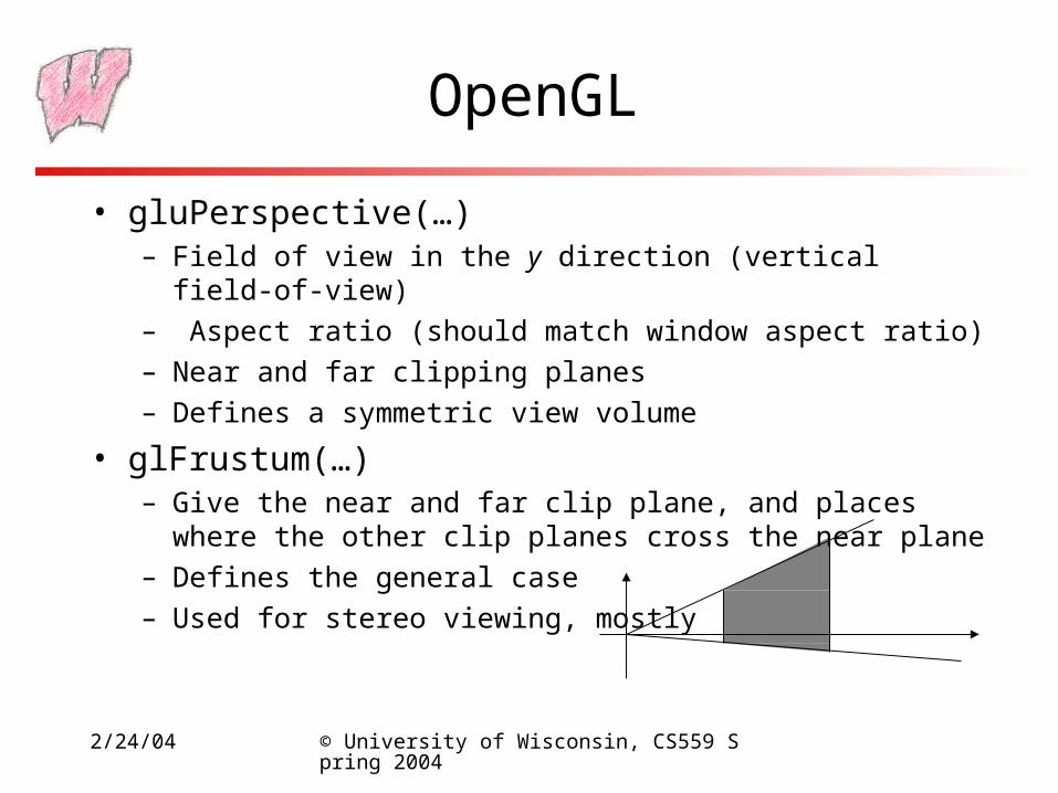
OpenGL
• gluPerspective(…)– Field of view in the y direction (vertical field-of-view)
– Aspect ratio (should match window aspect ratio)
– Near and far clipping planes
– Defines a symmetric view volume
• glFrustum(…)– Give the near and far clip plane, and places where the other clip
planes cross the near plane
– Defines the general case
– Used for stereo viewing, mostly
2/24/04 © University of Wisconsin, CS559 Spring 2004
Perspective Projection Matrices
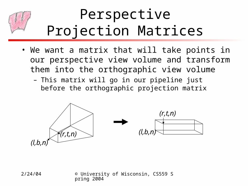
• We want a matrix that will take points in our perspective view volume and transform them into the orthographic view volume– This matrix will go in our pipeline just before the orthographic
projection matrix
(l,b,n)(r,t,n) (l,b,n)
(r,t,n)
2/24/04 © University of Wisconsin, CS559 Spring 2004
Mapping Lines
• We want to map all the lines through the center of projection to parallel lines– Points on lines through the center of projection map to the same
point on the image– Points on parallel lines map orthographically to the same point on
the image– If we convert the perspective case to the orthographic case, we can
use all our existing methods
• The intersection points of lines with the near clip plane should not change
• The matrix that does this, not surprisingly, looks like the matrix for our simple perspective case
2/24/04 © University of Wisconsin, CS559 Spring 2004
General Perspective
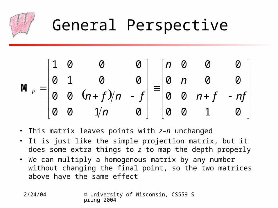
• This matrix leaves points with z=n unchanged
• It is just like the simple projection matrix, but it does some extra things to z to map the depth properly
• We can multiply a homogenous matrix by any number without changing the final point, so the two matrices above have the same effect
0100
00
000
000
0100
00
0010
0001
nffn
n
n
n
fnfnPM
2/24/04 © University of Wisconsin, CS559 Spring 2004
Complete Perspective Projection
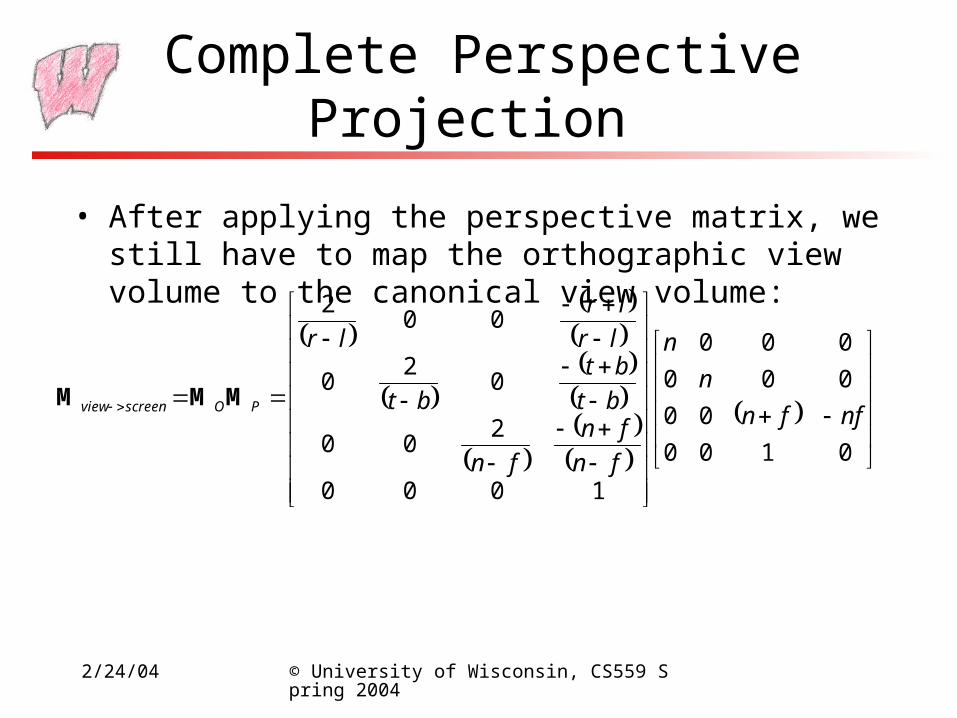
• After applying the perspective matrix, we still have to map the orthographic view volume to the canonical view volume:
0100
00
000
000
1000
200
02
0
002
nffn
n
n
fn
fn
fn
bt
bt
bt
lr
lr
lr
POscreenview MMM
2/24/04 © University of Wisconsin, CS559 Spring 2004
OpenGL Perspective Projection
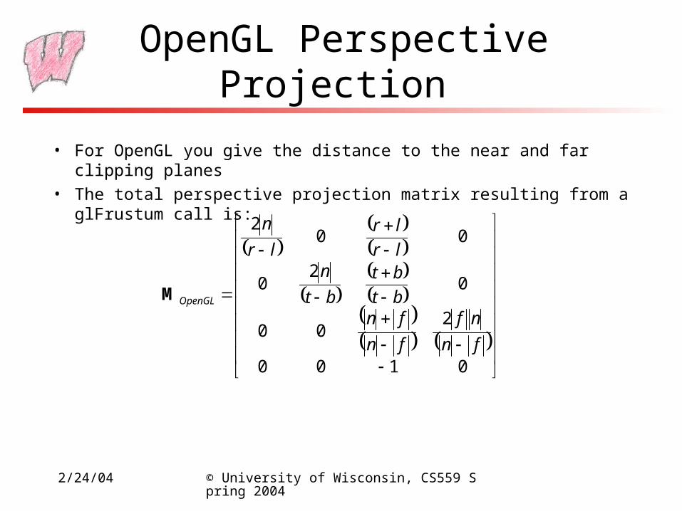
• For OpenGL you give the distance to the near and far clipping planes
• The total perspective projection matrix resulting from a glFrustum call is:
0100
200
02
0
002
fn
nf
fn
fnbt
bt
bt
nlr
lr
lr
n
OpenGLM
2/24/04 © University of Wisconsin, CS559 Spring 2004
Near/Far and Depth Resolution
• It may seem sensible to specify a very near clipping plane and a very far clipping plane– Sure to contain entire scene
• But, a bad idea:– OpenGL only has a finite number of bits to store screen depth– Too large a range reduces resolution in depth - wrong thing may be
considered “in front”– See Shirley for a more complete explanation
• Always place the near plane as far from the viewer as possible, and the far plane as close as possible

2/24/04 © University of Wisconsin, CS559 Spring 2004
Clipping
• Parts of the geometry to be rendered may lie outside the view volume– View volume maps to memory addresses– Out-of-view geometry generates invalid addresses– Geometry outside the view volume also behaves very strangely
under perspective projection• Triangles can be split into two pieces, for instance
• Clipping removes parts of the geometry that are outside the view
• Best done in screen space before perspective divide– Before dividing out the homogeneous coordinate
2/24/04 © University of Wisconsin, CS559 Spring 2004
Clipping
• Points are trivial to clip - just check which side of the clip planes they are on
• Many algorithms for clipping lines exist– Next lecture
• Two main algorithms for clipping polygons exist– Sutherland-Hodgman (today)
– Weiler (next lecture)
2/24/04 © University of Wisconsin, CS559 Spring 2004
Clipping Points
• A point is inside the view volume if it is on the “inside” of all the clipping planes– The normals to the clip planes are considered to point inward, toward the
visible stuff
• Now we see why clipping is done in canonical view space
• For instance, to check against the left plane:– X coordinate in 3D must be > -1
– In homogeneous screen space, same as: xscreen> -wscreen
• In general, a point, p, is “inside” a plane if:– You represent the plane as nxx+nyy+nzz+d=0, with (nx,ny,nz) pointing
inward
– And nxpx+nypy+nzpz+d>0


![Data Augmentation for Leaf Segmentation and Counting …...scenes [12]. Basic practices include rotations, cropping, color transforms; advanced methods are usually applied to specific](https://static.fdocuments.net/doc/165x107/6141310283382e045471ed58/data-augmentation-for-leaf-segmentation-and-counting-scenes-12-basic-practices.jpg)