22 WIPP Future Advancements and Operational Safety
24
WIPP Future Advancements and Operational Safety Rodney L. Whisenhunt, NWP Senior Project Manager, Capital Asset Projects
-
Upload
sandia-national-laboratories-energy-climate-renewables -
Category
Technology
-
view
56 -
download
0
Transcript of 22 WIPP Future Advancements and Operational Safety
WIPP Future Advancements and Operational Safety
Rodney L. Whisenhunt, NWPSenior Project Manager, Capital Asset Projects
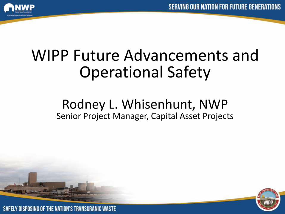
Historic Ventilation Modes at WIPP●Normal Mode - 2 main 700 fans in unfiltered operation – up
to 480,000 cfm●Alternate Mode - 1 main 700 fan in unfiltered operation –
280,000 cfm●Filtration Mode - 1 860 fan in filtered operation – 60,000 cfm●Operating one or two 860 fans in unfiltered (by-pass) mode
(reduced and minimum flow)●Operating a main 700 fan in parallel with a unfiltered (by-
pass) 860 fan (maintenance)
Note: Airflows shown are nominal and at surface fan location
Ventilation Upgrades Post Radiologic Event

Current Filtered Ventilation System – Adding the Interim Ventilation System (IVS) fans
●IVS added two additional filter units●Two 960 fans with each fan having a 27,000 cfm
capacity●Flow increased to 114,000 cfm●Limited ability to provide ventilation to the
construction and north circuits●Does allow for limited emplacement operations
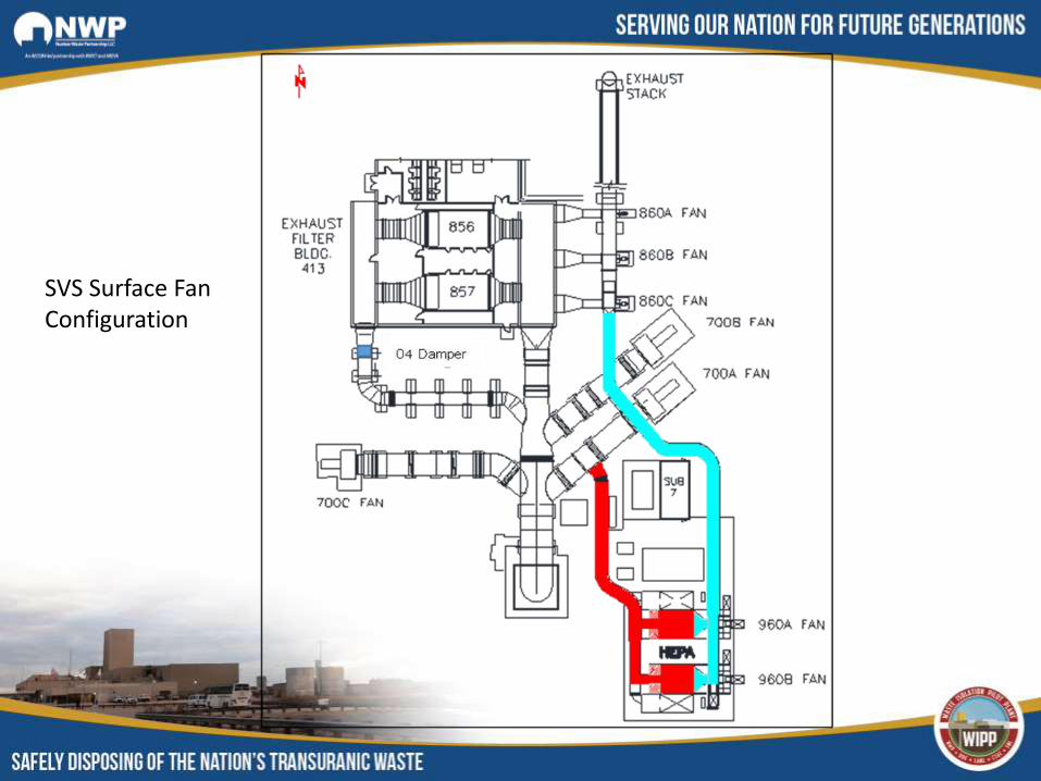
SVS Surface Fan Configuration

Filtered Ventilation System with Supplemental Ventilation System (SVS)
Fan in Operation●Exhaust flow is with UVS/IVS at 114,000 cfm at surface●SVS fan will pull air from the AIS and course the air to the
North and Construction Circuits●The Salt Handling Shaft will be on exhaust●Air to the disposal circuit is fixed at the UVS/IVS fan flow.
Air to the disposal circuit will be from the construction circuit
Long Term Ventilation Upgrades at WIPP
Long Range WIPP Planning
●WIPP was originally designed for 8 Panels with options for Panels 9 and 10.
●For planning purposes, NWP was directed by CBFO to extend the mission need to the year 2050.
●Other project direction was:●All exhaust air will be filtered from the disposal and
waste shaft station (NO unfiltered exhaust).●All underground activities, maintenance, waste
handling, mining, etc. will be performed in parallel.
Long Range Ventilation Goals at WIPP
●The use of the UVS/IVS/SVS systems will NOT be capable of meeting these long term goals at WIPP
●The original WIPP ventilation system will NOT be capable of meeting these mission statement needs.
●An upgrade to the surface exhaust and filter system is required
Long Range Ventilation Design Basis
●Assumed new panels would be constructed to the west of the existing repository.
●Panels would be identical to existing panels (room width and height, number of rooms, length of rooms, space between panels, and similar access airways)
●A repository life to the year 2050●From the receipt rate to 2050, the maximum
number of additional panels was estimated at 13
Long Range Ventilation Design Basis●Five main airways developed to the west. With
five airways, two will be for disposal intake.●Allows for ground control functions in one of the
intake mains without impacting waste handling operations.
●Mining will progress in a clockwise manner starting to the south nearest the existing repository mains●Minimizes mining to complete Panel 11 ●Reduces ventilation demand in early years

Long Range Ventilation Design
●Even without the radiation event in 2014, the Mission statement to emplace to 2050 would result in the need for:●New surface fans to accommodate distance to furthest panels●New shaft to replace aging Salt Handling Shaft and enhance
material handling capabilities●New shaft to separate construction air from disposal exhaust●New mining equipment (age of existing equipment would need
to be phased out)
WIPP Upgrade Projects
●Two new projects are considered to achieve the mission statement:●New surface fans with new filter system (sufficient for all
exhaust air as per DOE direction).●New shaft (to achieve long term goals at WIPP regarding
hoisting and separation of construction [mining] and waste handling operations)

Current New Filter Building (NFB) Design
●Principal underground ventilation design criteria for NFB●Maximum airflow of 540,000 cfm (at the fans)●Consider a salt reduction system to minimize salt
dust from reaching containment filters
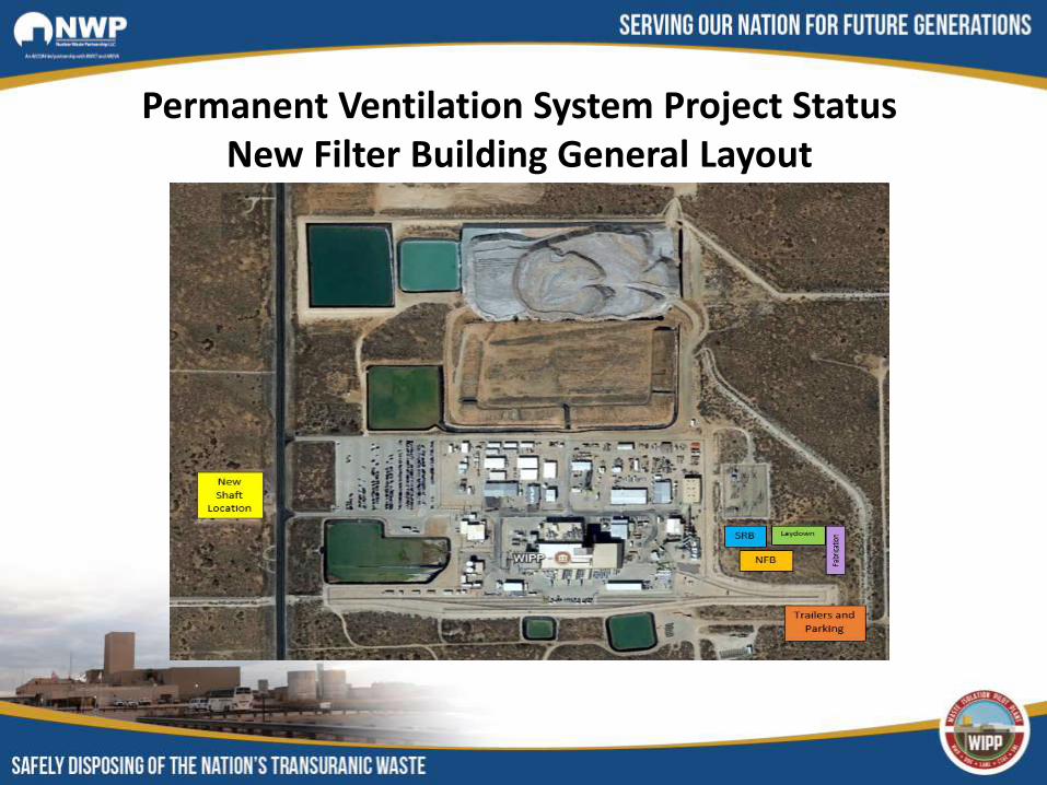
Permanent Ventilation System Project StatusNew Filter Building General Layout
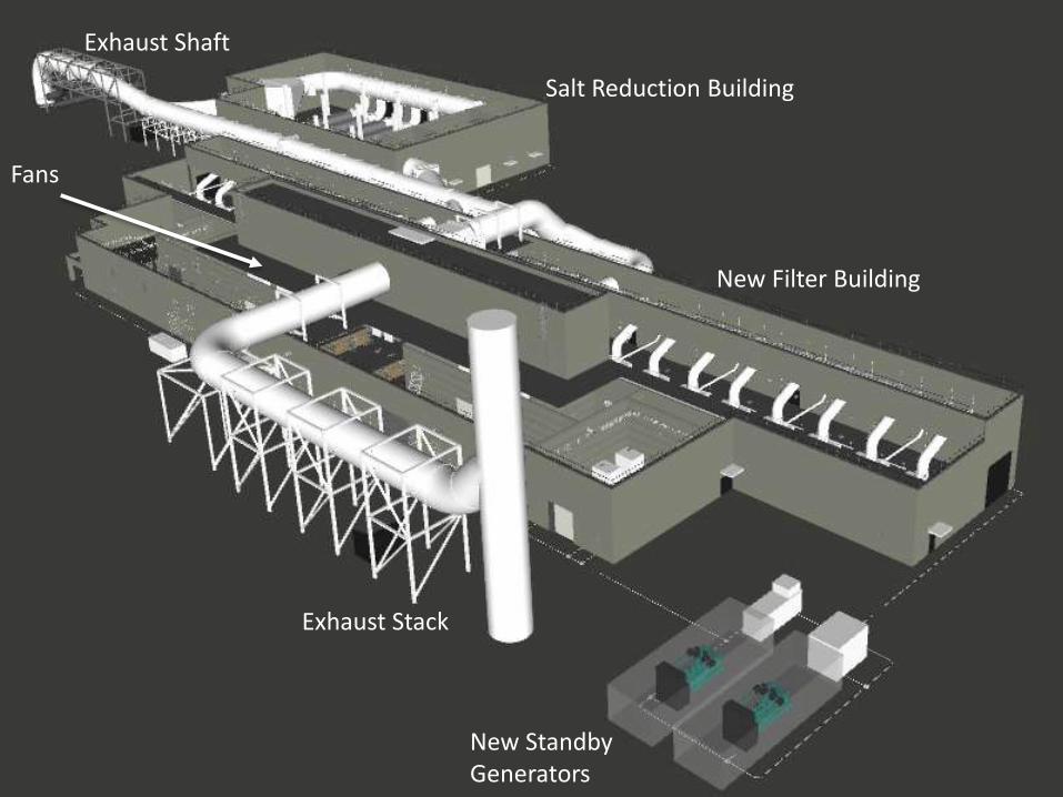
Salt Reduction Building
New Filter Building
New Standby Generators
Exhaust Stack
Fans
Exhaust Shaft
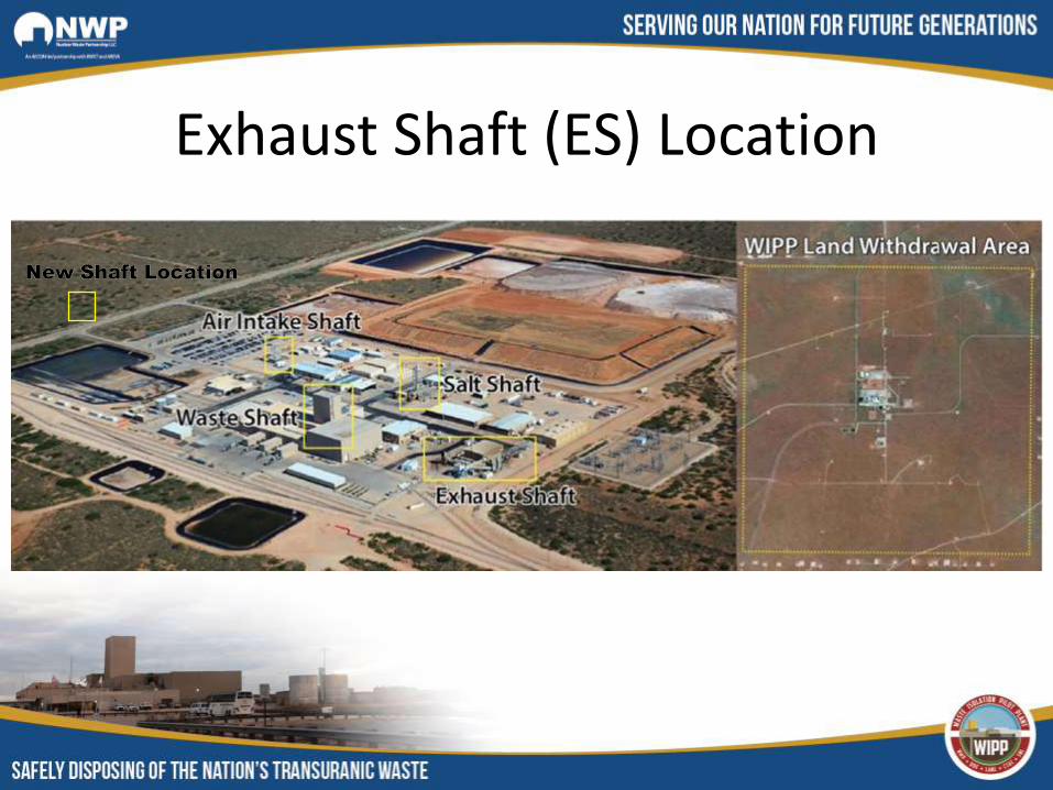
Exhaust Shaft (ES) Location
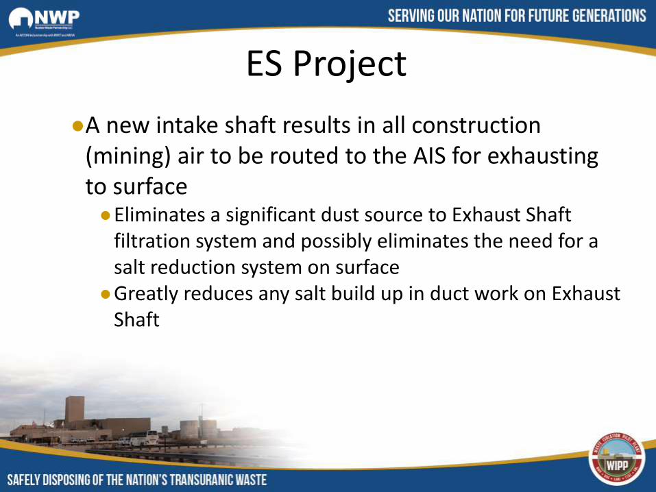
ES Project
●A new intake shaft results in all construction (mining) air to be routed to the AIS for exhausting to surface●Eliminates a significant dust source to Exhaust Shaft
filtration system and possibly eliminates the need for a salt reduction system on surface
●Greatly reduces any salt build up in duct work on Exhaust Shaft

Hoisting System in New Shaft
• The current project does not include a hoisting system
• A separate project is being considered to install a hoisting system in the new shaft.
New Shaft with Hoisting Capability
●The need for a hoisting system is based on the following criteria:● Increased salt handling operations● Increased personnel and materials handling operations
●The design would allow for salt skipping and personnel and material handling operations to occur simultaneously ●At least doubling current salt skipping operations●Large equipment can be hoisted via a large conveyance●Emergency egress is significantly enhanced
New Shaft with Hoisting Capability●Basis of new hoisting system design
●Need to replace existing Salt Handling Shaft (SHS)●The SHS has been in operation since the early 1980s and was
designed for a 25 year life (currently over 30 years old)●The current SHS is a small 10 ft. diameter shaft with
significant corrosion on internal shaft components. ●At some stage this shaft will need a major overhaul – which
will result in a cessation of salt skipping from the underground during shaft renovation.
●A complete shaft overhaul with updated controllers on the hoist system could take up to 12 months.
●This will impact mining to new panels to the west.
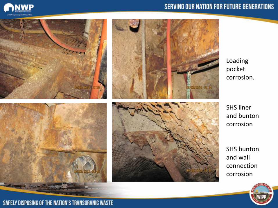
Loading pocket corrosion.
SHS liner and bunton corrosion
SHS bunton and wall connection corrosion
New Shaft with Hoisting Capability●The need for a hoisting system is based on the following
(continued):●The SHS has only an 8 ton skipping capacity for salt removal.
Bottlenecks were common with this limited skip capacity (storing salt in underground airways waiting to be skipped)
●The SHS has two functions, personnel and material conveyance and salt removal. The two functions CANNOToccur simultaneously.
● If the SHS is skipping salt, then all personnel and material handling is moved to the Waste Shaft – potentially limiting any waste handling operations.
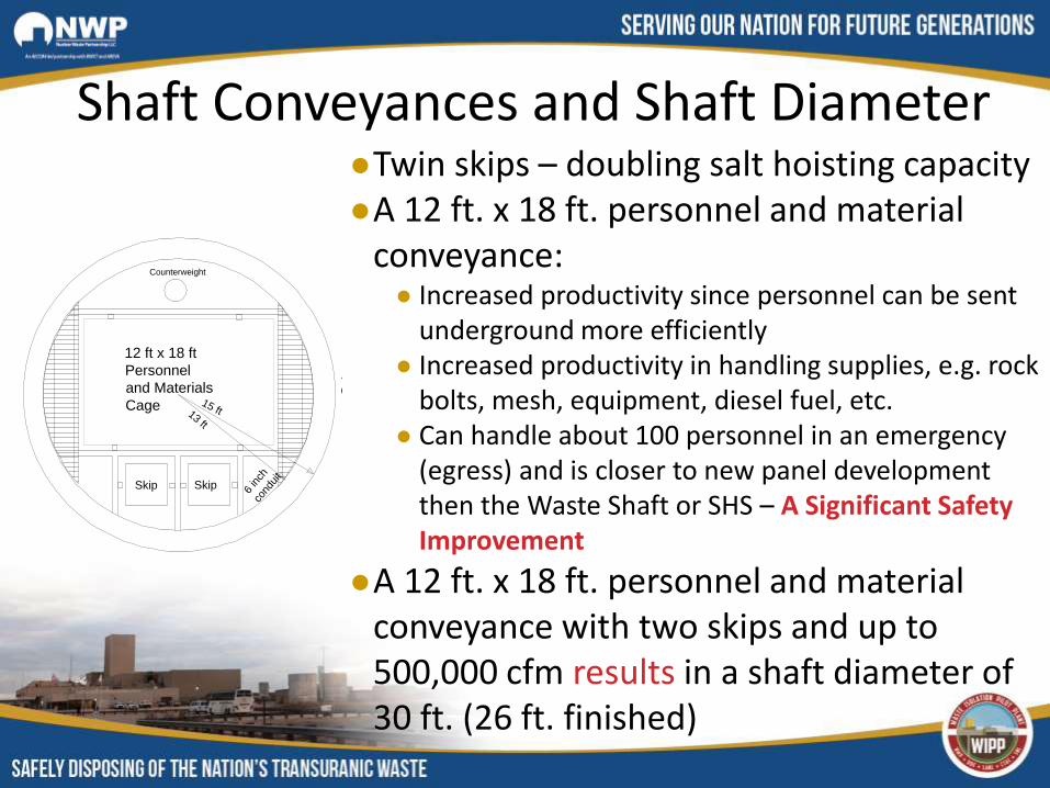
Shaft Conveyances and Shaft Diameter●Twin skips – doubling salt hoisting capacity ●A 12 ft. x 18 ft. personnel and material
conveyance:● Increased productivity since personnel can be sent
underground more efficiently● Increased productivity in handling supplies, e.g. rock
bolts, mesh, equipment, diesel fuel, etc.● Can handle about 100 personnel in an emergency
(egress) and is closer to new panel development then the Waste Shaft or SHS – A Significant Safety Improvement
●A 12 ft. x 18 ft. personnel and material conveyance with two skips and up to 500,000 cfm results in a shaft diameter of 30 ft. (26 ft. finished)
Access to
Cage
Skip Skip
12 ft x 18 ft
Personnel
and Materials
Cage
Counterweight
15 ft13 ft
6 in
chco
ndui
t
Access to
Cage