
22 JOURNAL OF COMMUNICATIONS SOFTWARE AND SYSTEMS, …
7
Comparison Between Finite and Boundary Element Methods for Analysis of Electrostatic Field Around Human Head Generated by Video Display Units Damir Čavka, Dragan Poljak, and Andres Peratta Abstract: Boundary and finite element modeling approach to the assessment of electrostatic field on human head generated by Video Display Units (VDU’s) are compared and discussed. Attention is focused to the field distribution over the surface of the face. The mathematical formulation for the assessment of the electrostatic field is based on the Laplace equation for the electric scalar potential. The electrostatic field is calculated for two different models of face. Numerical results are presented and compared in order to estimate the accuracy and computational efficiency of the two methods for the considered problem. In order to make comparison as meaningful as possible, boundary and finite element codes have been both developed by the authors. In general, boundary element appears to be the better choice than finite element with respect to computational efficiency and level of accuracy. Index Terms: Boundary element method (BEM), electrostatic field, finite element method (FEM), human head, video display units. I. INTRODUCTION Video display units (VDU’s), specially based on cathode ray tube (CRT), are sources of several types of radiation e.g. X ray radiation, optical radiation (ultraviolet radiation, visible light and infrared radiation) electromagnetic radiation and electrostatic field. Although CRT type monitors are now widely replaced by LCD (Liquid crystal display) and LED (Light emitted diode) displays, there are lots of them still in use world widely. With the expanding use of VDU’s some concerns about the effect of these fields on the human health have appeared. Over the years of work it has been noticed and proven that X ray radiation, optical radiation, high (~MHz) and low (~kHz) frequency electromagnetic fields are well below technical guidelines [1], [2] i.e. not considered to be harmful for the health. On the other hand, extremely low frequency (ELF) (~Hz) electromagnetic and electrostatic fields might be associated with some skin diseases, suppression of melatonin, or induction of phosphenes in the eyes, despite of the fact that there is no strong evidence of adverse health effects from Manuscript received October 27, 2010, revised March 23, 2011. This work has been partially supported by Ministry of Science and Technology, Croatia and British Foreign Office, UK. D. Čavka and D. Poljak are with the University of Split, Split, Croatia. (email: {dcavka, dragan.poljak}@fesb.hr). A. Peratta with the Wessex Institute of Tehcnology, Southampton, England, UK (e-mail: [email protected]). domestic levels of ELF electromagnetic fields [1]–[3] Also, the frequency of the alpha waves in human brain, is in the ELF range. The present work deals with electrostatic fields, as large electrostatic fields have been detected from several types of VDU’s and possibly related with skin rashes [3], [4]. Moreover, regarding health effects, the electrostatic fields are still neither fully investigated, nor completely understood. To the best of the author’s knowledge, no standards or guidelines exist for electrostatic fields. However, it has to be pointed out that the main concern related to the exposure to these fields is linked with particle transport and deposition [5]. Several classes of numerical methods are available for solving various problems in engineering, including finite difference method (FDM), finite element method (FEM) and boundary element method (BEM). FDM usually requires the geometry of the problem domain to be sufficiently simple in some rectangular or curvilinear coordinate system. On the other hand, the BEM and FEM have the dual advantage of being able to accommodate problem domains with complex geometries, while relying on a rigorous problem reformulation that is free of approximations present in finite difference formulation [6]–[12]. The Finite Element Method (FEM) [6]–[9] is widely used, especially because of its capability to treat any type of geometry and material inhomogeneity without a need to alter the formulation or computer code. So, it provides geometrical fidelity and unrestricted material treatment. Moreover, the application of the FEM leads to sparse and usually symmetric matrix systems which can be stored with low memory requirements. The main strength of the BEM [10]–[12] is the reduction of the problem dimensionality by one unit. Therefore, the number of unknowns in the resultant matrix system obtained by discretization is substantially reduced. A very important issue arising from the use of BEM or FEM in this type of problems is a trade-off between these methods regarding the accuracy and efficiency. Generally BEM has better accuracy because it is based on the fundamental solution of the leading partial differential equation (Green’s functions), the use of mixed formulations, i.e. one variable and the use of approximations that are restricted to the boundary. In BEM two types of variables are usually employed, such as potential and flux in Laplace problem, while in FEM only the potential is introduced as a 22 JOURNAL OF COMMUNICATIONS SOFTWARE AND SYSTEMS, VOL. 7, NO. 1, MARCH 2011 1845-6421/11/8225 © 2011 CCIS
Transcript of 22 JOURNAL OF COMMUNICATIONS SOFTWARE AND SYSTEMS, …

Comparison Between Finite and Boundary Element Methods for Analysis of Electrostatic Field Around
Human Head Generated by Video Display Units
Damir Čavka, Dragan Poljak, and Andres Peratta
Abstract: Boundary and finite element modeling approach to the assessment of electrostatic field on human head generated by Video Display Units (VDU’s) are compared and discussed. Attention is focused to the field distribution over the surface of the face. The mathematical formulation for the assessment of the electrostatic field is based on the Laplace equation for the electric scalar potential. The electrostatic field is calculated for two different models of face. Numerical results are presented and compared in order to estimate the accuracy and computational efficiency of the two methods for the considered problem. In order to make comparison as meaningful as possible, boundary and finite element codes have been both developed by the authors. In general, boundary element appears to be the better choice than finite element with respect to computational efficiency and level of accuracy.
Index Terms: Boundary element method (BEM), electrostatic
field, finite element method (FEM), human head, video display units.
I. INTRODUCTION
Video display units (VDU’s), specially based on cathode
ray tube (CRT), are sources of several types of radiation e.g. X ray radiation, optical radiation (ultraviolet radiation, visible light and infrared radiation) electromagnetic radiation and electrostatic field. Although CRT type monitors are now widely replaced by LCD (Liquid crystal display) and LED (Light emitted diode) displays, there are lots of them still in use world widely. With the expanding use of VDU’s some concerns about the effect of these fields on the human health have appeared. Over the years of work it has been noticed and proven that X ray radiation, optical radiation, high (~MHz) and low (~kHz) frequency electromagnetic fields are well below technical guidelines [1], [2] i.e. not considered to be harmful for the health.
On the other hand, extremely low frequency (ELF) (~Hz) electromagnetic and electrostatic fields might be associated with some skin diseases, suppression of melatonin, or induction of phosphenes in the eyes, despite of the fact that there is no strong evidence of adverse health effects from
Manuscript received October 27, 2010, revised March 23, 2011. This work has been partially supported by Ministry of Science and
Technology, Croatia and British Foreign Office, UK. D. Čavka and D. Poljak are with the University of Split, Split, Croatia.
(email: {dcavka, dragan.poljak}@fesb.hr). A. Peratta with the Wessex Institute of Tehcnology, Southampton,
England, UK (e-mail: [email protected]).
domestic levels of ELF electromagnetic fields [1]–[3] Also, the frequency of the alpha waves in human brain, is in the ELF range.
The present work deals with electrostatic fields, as large electrostatic fields have been detected from several types of VDU’s and possibly related with skin rashes [3], [4]. Moreover, regarding health effects, the electrostatic fields are still neither fully investigated, nor completely understood. To the best of the author’s knowledge, no standards or guidelines exist for electrostatic fields. However, it has to be pointed out that the main concern related to the exposure to these fields is linked with particle transport and deposition [5].
Several classes of numerical methods are available for solving various problems in engineering, including finite difference method (FDM), finite element method (FEM) and boundary element method (BEM). FDM usually requires the geometry of the problem domain to be sufficiently simple in some rectangular or curvilinear coordinate system. On the other hand, the BEM and FEM have the dual advantage of being able to accommodate problem domains with complex geometries, while relying on a rigorous problem reformulation that is free of approximations present in finite difference formulation [6]–[12].
The Finite Element Method (FEM) [6]–[9] is widely used, especially because of its capability to treat any type of geometry and material inhomogeneity without a need to alter the formulation or computer code. So, it provides geometrical fidelity and unrestricted material treatment. Moreover, the application of the FEM leads to sparse and usually symmetric matrix systems which can be stored with low memory requirements.
The main strength of the BEM [10]–[12] is the reduction of the problem dimensionality by one unit. Therefore, the number of unknowns in the resultant matrix system obtained by discretization is substantially reduced.
A very important issue arising from the use of BEM or FEM in this type of problems is a trade-off between these methods regarding the accuracy and efficiency. Generally BEM has better accuracy because it is based on the fundamental solution of the leading partial differential equation (Green’s functions), the use of mixed formulations, i.e. one variable and the use of approximations that are restricted to the boundary. In BEM two types of variables are usually employed, such as potential and flux in Laplace problem, while in FEM only the potential is introduced as a
22 JOURNAL OF COMMUNICATIONS SOFTWARE AND SYSTEMS, VOL. 7, NO. 1, MARCH 2011
1845-6421/11/8225 © 2011 CCIS
FESB
Typewritten Text
Original scientific paper

degree of freedom. The subsequent need to differentiate the potential in the case of FEM in order to compute fluxes considerably reduces the accuracy of the solution.
Since the approximations in BEM are restricted to the boundary, boundary element meshes should not be compared to the finite element meshes with the internal nodes removed. To achieve comparable accuracy finite element meshes would need more boundary divisions than the equivalent boundary element mesh. Despite of the vast literature on BEM and FEM methods, little is known about their relative performances, especially on the problems with complex geometries, like this one.
This article abuts on and extends the previous work by the authors related to the modeling of human exposure to electromagnetic fields. Exposure to the low frequency fields was examined in [13] and [14], where the problem was solved using BEM. BEM was also used to deal with electromagnetic-thermal analysis of human exposure to base station antennas radiations [15]. Another problem on high frequencies was considered in [16], where thermal rise in human eye caused by time harmonic electromagnetic wave was studied. Electromagnetic scattering part of the problem has been calculated via hybrid FEM/BEM approach, while the temperature rise by solving bio-heat transfer equation via standard FEM.
In the present paper, the realistic, three-dimensional, anatomically based model of the human head exposed to electrostatic field from VDU is presented. Contrary to the usual approach featuring the use of the FDM [3], the electrostatic field around human head is assessed using both BEM and FEM. The mathematical formulation is based on Laplace equation for electrostatic potential [17], [18]. To achieve more reliable results for the comparison purposes the field is calculated for two different faces. Comparison of the methods is made for the electrostatic field strength. Also, five characteristic spots were chosen on the faces in order to compare results in detail.
Computational aspects of both methods are outlined, as well.
II. MATHEMATICAL FORMULATION OF THE PROBLEM Assuming the charge density to be negligible in the space
between the person and the display, the mathematical description of the 3D electrostatic field between a VDU and human head is given by Laplace equation for electric potential φ [17], [18]: 2 0ϕ∇ = (1) with the associated boundary conditions: sϕ ϕ= on the display, (2) hϕ ϕ= on the head, (3)
0nϕ∇ ⋅ = on the far field boundaries. (4)
As shown in Fig. 1, the Dirichlet boundary conditions (2) and (3) are specified on the face and the display, respectively, while Neumann conditions (4) are imposed on the rest of the outer boundary. The reason for choosing the zero-normal electric field boundary condition on the far field boundaries instead infinite boundaries lies in the fact that infinite elements and FEM yield to demanding formulation with the problem of mesh truncation.
It is worth noting that the head is considered to be a perfect conductor thus being itself an equipotential surface with potential φh.
Fig 1. Geometry and boundary conditions for numerical 3D model of human seated in front of a VDU
Presented formulation involves the parameters ls, ds, φs and
φh, representing the distance between display and nose tip, the size of display (diagonal display size given in inches), the electrostatic potential on display and electrostatic potential on head, respectively. The mean electric potential on a CRT monitors is in the range of 1-15kV. In this case the electric potential of the display is assumed to be relatively very high (15 kV) and it is approximately considered to be the worst-case scenario. In the present work standard conditions for the person in front of display are defined as follows: ls=40cm, ds=17in, φs=15kV and φh=0kV. It is presumed that the monitor is 4:3 format type, meaning that width of the screen is 34.3 cm (13.6 in) and height is 25.7 cm (10.2 in). Also diameter of the computational domain is around 1 m, with the height of around 0.6 m. Size of the head follows the standards proposed by [19], i.e. head length of about 21 cm and head breadth of about 16.5 cm.
It is worth emphasizing that the eyebrows are assumed to have the same potential as the face. Other parameters such as temperature, humidity and conductivity of the screen glass surface are not taken into account in order to simplify the model. Nevertheless, it has to be underlined that air humidity is very important factor, and in these calculations is considered very low (dry air). Dry air approximation assures charge free air around the head meaning that the governing equation is Laplace equation.
ČAVKA et al.: COMPARISON BETWEEN FINITE AND BOUNDARY ELEMENT METHODS 23

Attention is given two different face geometries: person 1 (Fig. 2a) and person 2 (Fig. 2b) in order to achieve more reliable results and conclusions. Person 1 and person 2 represent two different races. First one represents adult African male person while other represents adult Asian male.
Fig. 2. Head models: a) Person 1 b) Person 2
The preprocessing and the geometry implementation
represent a major problem that has been handled by customizable geometry modeler, a preprocessor, and mesh generator (GID) [20].
III. NUMERICAL SOLUTION For the sake of completeness an outline of the BEM and
FEM is presented in this section, respectively. More details can be found in the related references.
A. Boundary element solution The boundary integral version of (1) is given as:
Γ∂∂
−Γ∂∂
= ∫∫ΓΓ
dn
dn
c iiψϕϕψϕ (5)
Where ψ is the fundamental solution Laplace equation:
( ) 14 Rψ π −= , 'rrR −= is the distance between the source
point i and field point in Γ, and:
⎪⎩
⎪⎨⎧
Γ∈Ω∈
= )(,21,1
boundarysmoothii
ci (6)
Boundary discretisation and further collocation into Nfs
degrees of freedom yields an algebraic linear system of equations of the form [10] – [12]:
BEM =A x b (7)
where BEMA is fe feN N× matrix that involves the
coefficients o f the single and double layer potential operators, i.e. the coefficients of H and G matrices in [18], the 1-column array of unknowns x contains the potentials and normal fluxes that were not prescribed as boundary conditions, and the right hand side term involves boundary conditions.
B. Finite element solution A weighting residual approach to (1) yields [6]–[9]:
2 0jW dϕ
Ω
∇ Ω =∫ (8)
where W is the weighting function. Then, assuming weak
formulation of the problem defined by (1)-(4), Gauss theorem and Galerkin Bubnov collocation technique (Wj=Nj), where Nj are linear interpolating functions), the integral formulation (variational equation) of (1) becomes:
j jN d N dnϕϕ
Ω Γ
∂∇ ⋅∇ Ω = Γ
∂∫ ∫ (9)
The unknown potential across the element is expressed as a
linear combination of 4 shape functions (N) [21] as follows:
4
1
ei i
iNϕ α
=
= ∑ (10)
where {α} represents unknown coefficients of the solution.
Equations (31) to (33) results in the global matrix system: { } { } FEM Qα =A (11)
where {Q} represents the flux vector., and global matrix
FEMA is composed of local finite element matrices [ ]e
jia .
Once obtained the potentialϕ , the E field can be calculated
from the potential gradient E ϕ= −∇ as indicated in [12].
IV. NUMERICAL RESULTS
C. Person 1 Both BEM and FEM meshes were generated using the
general pre-processor and geometry modeler GiD [19]. The BEM mesh consists of 4558 constant triangle elements and 4558 nodes, while FEM mesh consists of 80771 linear tetrahedral elements (20184 nodes).
Fig. 3 shows the electrostatic field strength E [V/cm] on the face of person 1 for FEM and BEM solutions, respectively, for standard conditions.
24 JOURNAL OF COMMUNICATIONS SOFTWARE AND SYSTEMS, VOL. 7, NO. 1, MARCH 2011

Fig. 3. Electrostatic field strength in V/cm on the face of the person 1
a) FEM solution (left); b) BEM solution (right)
At a glance, it can be stated that both methods yield same pattern distribution, i.e. the field strengths and the behavior of the field on the face is almost the same. Maximal field strength at the face is noticed on the nose tip and around it. Significant values of the field are present on the lips, chin and forehead. Interesting part of the face is area around eyes where field strength is not so large (around 300 – 400 V/cm) comparing with nose (around 1800 V/cm). But, some differences between the solutions are clearly noticeable. The model of human head is symmetrical, so it is expected that the field strengths are equal and symmetric on the both sides of the face. Exact symmetry is present only in BEM solution, while certain asymmetries have appeared within FEM solution. Nevertheless, these differences are not so significant, they point out first weakness of the FEM solution. Within the FEM solution some “hot spots” can be noticed on the nose (≈1960 V/cm), heaving much higher values of the field then the same spots on the BEM model (≈1760 V/cm). Also there are some spots that have much lower value of electrostatic field then the same spots on the BEM model.
Differences on the certain spots and asymmetry of the FEM solution can be explained by the fact that it is very hard to get good, quality and sufficiently refined finite element mesh around complex geometries like the human face, that is in the same time symmetrical.
To examine and compare BEM and FEM solutions more
detailed, five characteristic (specific) spots (locations) on face were chosen, shown in Fig. 4:
1) Spot on the nose tip, 2) Spot on the nose approximately 2 cm above nose tip, 3) Spot on the nose approximately 1 cm side from the nose
tip, 4) Spot on the forehead approximately 8 cm above nose
tip and 5) Spot at the centre of the eye. Three spots on the nose were chosen because maximal field
strengths were found around nose tip, spot on the eye because of eye sensitivity and forehead spot because forehead is relatively flat and therefore results are very uniform providing good reference point for comparison.
Fig. 4. Five characteristic spots on the face of a person 1
Fig. 5 shows comparison of BEM and FEM results for
electrostatic field E [V/cm] at specific locations for person 1.
Fig. 5. Electrostatic field strength at the specific locations (person 1)
The results show good agreement between BEM and FEM.
The maximal relative difference is noticed on the nose tip, around 15%, or in absolute value around 260 V/cm, while the minimal relative difference is noticed at the nose (above tip), less then 1%.
D. Person 2 Boundary element mesh consist of 6066 constant triangle
elements (6066 nodes), while finite element mesh contains 104082 linear tetrahedral elements (26659 nodes).
Results for electrostatic field strength E[V/cm] on the face of the person 2, for standard conditions, obtained by FEM and BEM method, respectively, are shown in Fig. 6.
Fig. 6. Electrostatic field strength in V/cm on the face of the person 2
a) FEM solution; b) BEM solution
ČAVKA et al.: COMPARISON BETWEEN FINITE AND BOUNDARY ELEMENT METHODS 25
Again, as in the case of person 1, very similar results can be observed from both solutions. Nature and the behavior of the field seem to be very alike. High field strength levels are found on the nose (maximal), lips, chin, forehead and eyebrows. Eyes and neighboring regions are not so exposed (around 300 – 400 V/cm) compared with the nose (maximal value around 2100 V/cm).
Comparing these results with the results for person 1, very different values of field strength are noticed, especially on certain parts of the face, like nose. The discrepancies are caused by the different shape of the face, particularly the shape of the nose. For most of the face area, the difference is not so significant, but nevertheless it proves that the field strength is highly dependent on the shape of the face.
The same conclusions can be drawn, concerning differences between two solutions. Due to geometrically symmetrical head, the results for electrostatic field should be symmetrical as well. The BEM solution gives exactly symmetrical results, while FEM results show some asymmetries due to disability to generate good, quality and sufficiently refined finite element mesh around complex geometry of the human face.
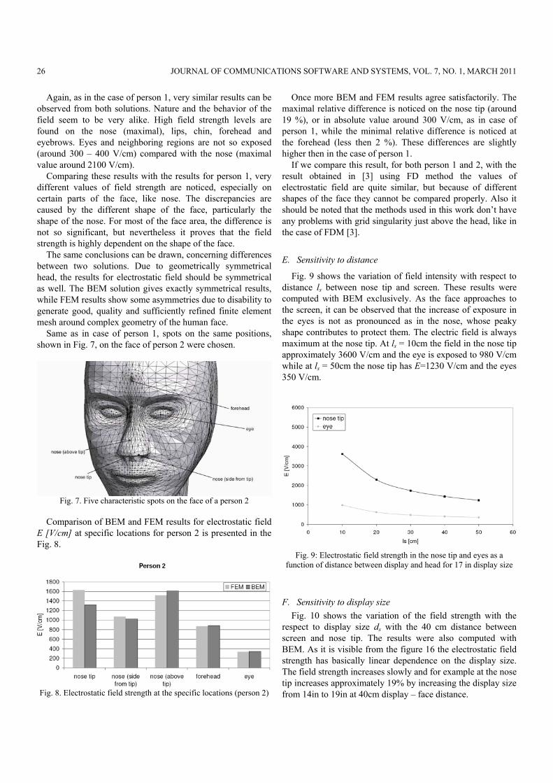
Same as in case of person 1, spots on the same positions, shown in Fig. 7, on the face of person 2 were chosen.
Fig. 7. Five characteristic spots on the face of a person 2
Comparison of BEM and FEM results for electrostatic field
E [V/cm] at specific locations for person 2 is presented in the Fig. 8.
Fig. 8. Electrostatic field strength at the specific locations (person 2)
Once more BEM and FEM results agree satisfactorily. The maximal relative difference is noticed on the nose tip (around 19 %), or in absolute value around 300 V/cm, as in case of person 1, while the minimal relative difference is noticed at the forehead (less then 2 %). These differences are slightly higher then in the case of person 1.
If we compare this result, for both person 1 and 2, with the result obtained in [3] using FD method the values of electrostatic field are quite similar, but because of different shapes of the face they cannot be compared properly. Also it should be noted that the methods used in this work don’t have any problems with grid singularity just above the head, like in the case of FDM [3].
E. Sensitivity to distance
Fig. 9 shows the variation of field intensity with respect to distance ls between nose tip and screen. These results were computed with BEM exclusively. As the face approaches to the screen, it can be observed that the increase of exposure in the eyes is not as pronounced as in the nose, whose peaky shape contributes to protect them. The electric field is always maximum at the nose tip. At ls = 10cm the field in the nose tip approximately 3600 V/cm and the eye is exposed to 980 V/cm while at ls = 50cm the nose tip has E=1230 V/cm and the eyes 350 V/cm.
Fig. 9: Electrostatic field strength in the nose tip and eyes as a
function of distance between display and head for 17 in display size
F. Sensitivity to display size Fig. 10 shows the variation of the field strength with the
respect to display size ds with the 40 cm distance between screen and nose tip. The results were also computed with BEM. As it is visible from the figure 16 the electrostatic field strength has basically linear dependence on the display size. The field strength increases slowly and for example at the nose tip increases approximately 19% by increasing the display size from 14in to 19in at 40cm display – face distance.
26 JOURNAL OF COMMUNICATIONS SOFTWARE AND SYSTEMS, VOL. 7, NO. 1, MARCH 2011
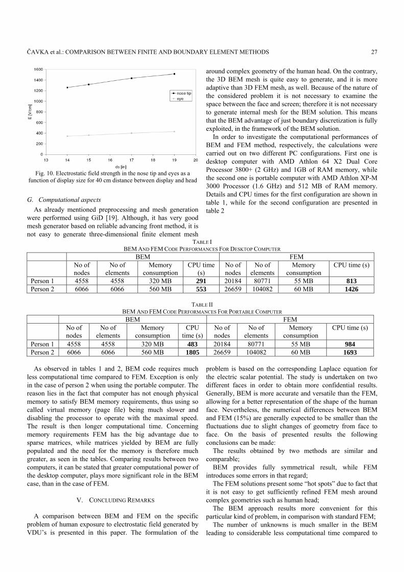
Fig. 10. Electrostatic field strength in the nose tip and eyes as a
function of display size for 40 cm distance between display and head
G. Computational aspects As already mentioned preprocessing and mesh generation
were performed using GiD [19]. Although, it has very good mesh generator based on reliable advancing front method, it is not easy to generate three-dimensional finite element mesh
around complex geometry of the human head. On the contrary, the 3D BEM mesh is quite easy to generate, and it is more adaptive than 3D FEM mesh, as well. Because of the nature of the considered problem it is not necessary to examine the space between the face and screen; therefore it is not necessary to generate internal mesh for the BEM solution. This means that the BEM advantage of just boundary discretization is fully exploited, in the framework of the BEM solution.
In order to investigate the computational performances of BEM and FEM method, respectively, the calculations were carried out on two different PC configurations. First one is desktop computer with AMD Athlon 64 X2 Dual Core Processor 3800+ (2 GHz) and 1GB of RAM memory, while the second one is portable computer with AMD Athlon XP-M 3000 Processor (1.6 GHz) and 512 MB of RAM memory. Details and CPU times for the first configuration are shown in table 1, while for the second configuration are presented in table 2
TABLE I BEM AND FEM CODE PERFORMANCES FOR DESKTOP COMPUTER
BEM FEM No of
nodes No of
elements Memory
consumption CPU time
(s) No of nodes
No of elements
Memory consumption
CPU time (s)
Person 1 4558 4558 320 MB 291 20184 80771 55 MB 813 Person 2 6066 6066 560 MB 553 26659 104082 60 MB 1426
TABLE II
BEM AND FEM CODE PERFORMANCES FOR PORTABLE COMPUTER BEM FEM No of
nodes No of
elements Memory
consumption CPU
time (s) No of nodes
No of elements
Memory consumption
CPU time (s)
Person 1 4558 4558 320 MB 483 20184 80771 55 MB 984 Person 2 6066 6066 560 MB 1805 26659 104082 60 MB 1693
As observed in tables 1 and 2, BEM code requires much less computational time compared to FEM. Exception is only in the case of person 2 when using the portable computer. The reason lies in the fact that computer has not enough physical memory to satisfy BEM memory requirements, thus using so called virtual memory (page file) being much slower and disabling the processor to operate with the maximal speed. The result is then longer computational time. Concerning memory requirements FEM has the big advantage due to sparse matrices, while matrices yielded by BEM are fully populated and the need for the memory is therefore much greater, as seen in the tables. Comparing results between two computers, it can be stated that greater computational power of the desktop computer, plays more significant role in the BEM case, than in the case of FEM.
V. CONCLUDING REMARKS
A comparison between BEM and FEM on the specific
problem of human exposure to electrostatic field generated by VDU’s is presented in this paper. The formulation of the
problem is based on the corresponding Laplace equation for the electric scalar potential. The study is undertaken on two different faces in order to obtain more confidential results. Generally, BEM is more accurate and versatile than the FEM, allowing for a better representation of the shape of the human face. Nevertheless, the numerical differences between BEM and FEM (15%) are generally expected to be smaller than the fluctuations due to slight changes of geometry from face to face. On the basis of presented results the following conclusions can be made:
The results obtained by two methods are similar and comparable;
BEM provides fully symmetrical result, while FEM introduces some errors in that regard;
The FEM solutions present some “hot spots” due to fact that it is not easy to get sufficiently refined FEM mesh around complex geometries such as human head;
The BEM approach results more convenient for this particular kind of problem, in comparison with standard FEM;
The number of unknowns is much smaller in the BEM leading to considerable less computational time compared to
ČAVKA et al.: COMPARISON BETWEEN FINITE AND BOUNDARY ELEMENT METHODS 27

FEM; On the other hand, BEM solution matrix is fully populated,
while FEM matrix is larger but sparsely populated leading in greater memory requirements in the BEM case. This particular issue can be properly addressed by adopting a reduction technique for BEM, such as Fast Multipole Method, panel clustering or domain decomposition.
To summarize, standard BEM is more suitable than standard FEM in terms of efficiency and stability for solving the linear problem of the human head exposed to VDU.
REFERENCES [1] International Commission on Non-Ionizing Radiation Protection
(ICNIRP) and International labour organization: “Visual display units: Radiation protection guidelines”, International labour office, Geneva 1994.
[2] Institute of Electrical and Electronics Engineers: “Biological and health effects of electric and magnetic fields from video display terminals”, IEEE Engineering in Medicine and Biology Magazine 16(3): 87-92, 1997.
[3] N.F. Nielsen, J. Michelsen, J.A. Michalsen, T. Schneider: Numerical calculation of electrostatic field surrounding a human head in visual display environments, Journal of Electrostatics, 36, pp. 209-223, 1996.
[4] Australian Radiation Protection and Nuclear Safety Agency: “Radiation Emission from Video Display Terminals”, Australian Radiation Protection and Nuclear Safety Agency, 2003.
[5] N.F. Nielsen, T. Schneider: Particle Deposition onto a Human Head: Influence of Electrostatic and Wind Fields, Bioelectromagnetics 19, pp. 246-258, 1998.
[6] D. Poljak, N. Kovac, V. Doric: “Numerical methods in Electrical Engineering”, FESB Split 2006.(in Croatian).
[7] V. Jovic: “Introduction in numerical modeling”, Aquarius engineering, Split, 1993. (in Croatian).
[8] J.L. Volakis, A. Chatterjee, L.C. Kempel: “Finite Element Method for Electromagnetics”, IEEE Press, 1998.
[9] O.C. Zienkiewicz, R.L. Taylor, The finite element method, fifth edition, Butterworth-Heinemann Oxford 2000.
[10] C.A. Brebbia, J. Dominguez; “Boundary Elements, An Introductory Course”, second edition. WIT Press: Boston, Southampton 1998.
[11] A.A. Becker: “The Boundary Element Method in Engineering”, McGraw-Hill Book Company, University Press, Cambridge 1992.
[12] D. Poljak, C.A. Brebbia: “Boundary Element Methods For Electrical Engineers”, WIT Press, Southampton, Boston 2005.
[13] M.G. Gonzalez, A. Peratta, D. Poljak: Boundary Element Modeling of the Realistic Human Body Exposed to Extremely-Low-Frequency (ELF) Electric Fields: Computational and Geometrical Aspects, IEEE Trans. Electromagnetic Compatibility, vol. 49, No 1, pp. 153 – 162,Feb. 2007.
[14] A. Peratta, C. Gonzalez, D. Poljak: Current Density Induced in the Human Body due to Power Distribution Lines using the Boundary Element Method, Journal of communications, software and systems – Special Issue on Environmental Electromagnetic Compatibility, vol. 3, No 1, pp 11 – 16, March 2007.
[15] D. Poljak, A. Peratta, C.A. Brebbia: The boundary element electromagnetic–thermal analysis of human exposure to base station antennas radiation, Eng. Anal. Bound. Elem. 28 (2004) 763 – 770.
[16] H. Dodig, A. Peratta, D. Poljak: Analysis Method for the Hating of the Human Eye Exposed to High Frequency Electromagnetic Fields, Journal of communications, software and systems – Special Issue on Environmental Electromagnetic Compatibility, vol. 3, No 1, pp 3 – 10, March 2007.
[17] D. Cavka, D. Poljak, A. Peratta: Finite element model of the human head exposed to electrostatic field generated by Video Display Units, Proc. of IEEE International Conference SoftCOM 2006, SYM1/I-6122-2909, Split (Croatia), 2006.
[18] D. Cavka, D. Poljak, A. Peratta, C.A. Brebbia: Boundary element model of the human head exposed to electrostatic field generated by Video Display Units, in Proc. Boundary Elements and Other Mesh Reduction Methods XXX, Southampton, WIT Press, UK, 2008. 115-124.
[19] NASA: “Man-Systems Integration Standards: Anthropometry and Biomechanics”, Washington, July 1995;
[20] International Center for Numerical methods in Engineering (CIMNE), Barcelona, Spain, GID resources [Online]. Available: http://gid.cimne.upc.es
[21] D. Cavka: Finite element thermal model of the human exposed to electric field generated from GSM base station, Proc. of IEEE International Conference SoftCOM 2006, SYM1/I-6123-2909, Split, 2006
Damir Cavka was born in Split, Croatia, in 1982. He received the B.Sc. degree in electrical engineering from the University of Split in 2005, and the M.Phil. degree from the University of Wales, in 2007. Since, May 2006, he has been Young Researcher at the Department of Electronics at University of Split. He is currently finishing his PhD thesis on the subject of computational
electromagnetics.
Dragan Poljak was born in Split, Croatia, in 1965. He received the B.Sc. and the M.Sc. degrees and the Ph.D. degree in electrical engineering from theUniversity of Split, Split, in 1990, 1994, and 1996, respectively. He is currently a Full Professor in the Department of Electronics, University of Split. He is also an Adjunct Professor at Wessex Institute of Technology (WIT), Ashurst, U.K. He has
authored or coauthored nearly 200 journal and conference papers in the area of computational electromagnetics, and seven books. He was awarded the National Prize for Science.
Andres Peratta received the M.Sc. degree in physics from the
University of Buenos Aires, Buenos Aires, Argentina, in 2001 and the Ph.D. degree from the University of Wales, Aberystwyth, U.K., in 2004. During 2005, he was a Postdoctoral Fellow and an Assistant Professor atWessex Institute of Technology (WIT), Southhampton, U.K., where he is currently the Head of the ICE Division.. His current research interests include numerical modeling, boundary and finite element
methods, electromagnetism, computational fluid dynamics, and continuum mechanics.
28 JOURNAL OF COMMUNICATIONS SOFTWARE AND SYSTEMS, VOL. 7, NO. 1, MARCH 2011