21ch MiniatureComponents f v3 · 2018-06-28 · no translation of the optic. The precision flexure...
20
1 21.31 reflective optics can be aligned. Holders for mirrors, lenses, and other optics simply attach to the front of each of these adjustable mounts. The MicroLab system is designed for optical components that typically range from 5 to 15 mm in size. Since small optics are dif- ficult to handle, a series of optical mounting cells is available to use with them. Once mounted in a cell, lenses can be handled easily. Cell-mounted lenses and other optics can be tilted with a mirror/optics mount or translated with a y-z positioner. For max- imum mounting flexibility, an adjustable lens holder is also offered. Fiber optics, mounted in a V-groove fiber holder, can be aligned with a y-z positioner and translation stage (go to page 21.7). A prism/tilt table with integral rotation is ideal for aligning right-angle prisms or cube beamsplitters. The optic is securely held down with a component retainer. A filter holder, designed to hold round or square flat optical components, is also available. Precision rotation of polarizers and retardation plates can be accomplished with either the single or double polarizer holder. MicroLab™ Component Holders ASK ABOUT OUR CUSTOM CAPABILITIES OEM Miniature Components www.mellesgriot.com Miniature Components Fixed Optical Mounts and Laser Holders Adjustable Optical Mounts Mounting Posts, Bases, and Brackets Optical Rails and Lab Jacks $ Mirror and beamsplitter mounts $ Lens holders $ Optical component cell systems $ Prism/tilt table $ Polarizer holders $ Fiber holders Stable optical component holders are critical for aligning any optical system. Melles Griot manufactures a comprehensive range of MicroLab™ component holders designed to satisfy any align- ment need. Each mount is designed to be as compact as possible, yet still convenient to use. Because they are all either post or base mountable, it is simple to build and align optical systems. Kinematic mirror mounts provide precise angular alignment for most applications. Gimbal mirror and beamsplitter mounts maintain the optical path length during adjustment since there is no translation of the optic. The precision flexure mirror/optics mount has a 16-mm-diameter aperture so that both transmissive and Holders are available for a wide range of optics and accessories.
Transcript of 21ch MiniatureComponents f v3 · 2018-06-28 · no translation of the optic. The precision flexure...

1 21.31
reflective optics can be aligned. Holders for mirrors, lenses, andother optics simply attach to the front of each of these adjustablemounts.
The MicroLab system is designed for optical components thattypically range from 5 to 15 mm in size. Since small optics are dif-ficult to handle, a series of optical mounting cells is available to usewith them. Once mounted in a cell, lenses can be handled easily.Cell-mounted lenses and other optics can be tilted with a mirror/optics mount or translated with a y-z positioner. For max-imum mounting flexibility, an adjustable lens holder is also offered.
Fiber optics, mounted in a V-groove fiber holder, can be alignedwith a y-z positioner and translation stage (go to page 21.7). Aprism/tilt table with integral rotation is ideal for aligning right-angleprisms or cube beamsplitters. The optic is securely held down witha component retainer. A filter holder, designed to hold round orsquare flat optical components, is also available. Precision rotationof polarizers and retardation plates can be accomplished with eitherthe single or double polarizer holder.
MicroLab™Component Holders
A S K A B O U T O U R C U S T O M C A P A B I L I T I E SO E M Miniature Components
w w w . m e l l e s g r i o t . c o m Miniature Com
ponentsFixed O
ptical Mounts
and Laser Holders
Adjustable O
ptical Mounts
Mounting Posts, Bases, and Brackets
Optical Rails and Lab Jacks
$ Mirror and beamsplitter mounts
$ Lens holders
$ Optical component cell systems
$ Prism/tilt table
$ Polarizer holders
$ Fiber holders
Stable optical component holders are critical for aligning anyoptical system. Melles Griot manufactures a comprehensive rangeof MicroLab™ component holders designed to satisfy any align-ment need. Each mount is designed to be as compact as possible,yet still convenient to use. Because they are all either post or basemountable, it is simple to build and align optical systems.
Kinematic mirror mounts provide precise angular alignmentfor most applications. Gimbal mirror and beamsplitter mountsmaintain the optical path length during adjustment since there isno translation of the optic. The precision flexure mirror/opticsmount has a 16-mm-diameter aperture so that both transmissive and
Holders are available for a wide range of optics and accessories.
21ch_MiniatureComponents_f_v3.qxd 6/8/2005 10:46 AM Page 21.31

21.32 1 A S K A B O U T O U R C U S T O M C A P A B I L I T I E SO E MMiniature Components
w w w . m e l l e s g r i o t . c o m
Min
iatu
re C
ompo
nent
sFi
xed
Opt
ical
Mou
nts
and
Lase
r H
olde
rsA
djus
tabl
e O
ptic
al M
ount
sM
ount
ing
Post
s, B
ases
, and
Bra
cket
sO
ptic
al R
ails
and
Lab
Jack
s
MiniatureMirror/Beamsplitter Mounts
dimensions in mm
f12.8 f9
19.5
10
2 holes threaded M4
6 maxthickness
40
40
2 holesthreaded M2
20
07 MEG 501 gimbal mirror mount
Component Maximum Optical
Diameter Clear Edge Axis
Range Aperture Thickness Height PRODUCT
(mm) (mm) (mm) (mm) NUMBER
12.5–12.7 9.0 6 20 07 MEG 501
Miniature Gimbal Mirror Mount
Miniature Gimbal Mirror Mount $ Self-contained true gimbal mechanism
$ High-strength hexagonally shaped body
$ Post or base mountable
This gimbal mirror mount provides 82.5 degrees of preciseangular adjustment about two orthogonal axes which intersect atthe center of the front surface of the optic. The length of the opti-cal path, therefore, remains constant during adjustment.
Optics from 12.5 to 12.7 mm (0.5 inch) are held in this mountwith a retaining ring. Mirrors up to 6 mm in thickness and platebeamsplitters up to 1 mm in thickness can be mounted.
Precision stainless steel 0.35-mm-pitch (73-TPI) adjustmentscrews yield an angular resolution of 13 arc seconds. TwoM4-threaded and two M2-threaded holes are provided to postmount or to attach an 07 ACF 501 base mounting adaptor (go topage 21.39). The gimbal mount is made of black-anodized aluminum.
07 MEG 501 is used to fold the optical path in thisapplication.
Gimbal mirror mounts pivot the mirror’s surface about theaxes of rotation.
21ch_MiniatureComponents_f_v3.qxd 6/8/2005 10:46 AM Page 21.32
1 21.33A S K A B O U T O U R C U S T O M C A P A B I L I T I E SO E M
Miniature Com
ponentsFixed O
ptical Mounts
and Laser Holders
Adjustable O
ptical Mounts
Mounting Posts, Bases, and Brackets
Optical Rails and Lab JacksMiniature Components
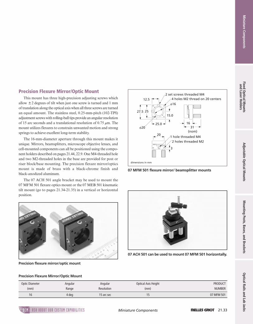
Precision Flexure Mirror/Optic MountThis mount has three high-precision adjusting screws which
allow 82 degrees of tilt when just one screw is turned and 1 mmof translation along the optical axis when all three screws are turnedan equal amount. The stainless steel, 0.25-mm-pitch (102-TPI)adjustment screws with rolling-ball tips provide an angular resolutionof 15 arc seconds and a translational resolution of 0.75 mm. Themount utilizes flexures to constrain unwanted motion and strongsprings to achieve excellent long-term stability.
The 16-mm-diameter aperture through this mount makes itunique. Mirrors, beamsplitters, microscope objective lenses, andcell-mounted components can all be positioned using the compo-nent holders described on pages 21.44, 22.9. One M4-threaded holeand two M2-threaded holes in the base are provided for post orriser block/base mounting. The precision flexure mirror/opticsmount is made of brass with a black-chrome finish andblack-anodized aluminum.
The 07 ACH 501 angle bracket may be used to mount the07 MFM 501 flexure optics mount or the 07 MEB 501 kinematictilt mount (go to pages 21.34-21.35) in a vertical or horizontal position.
dimensions in mm
20
3
2 holes threaded M21 hole threaded M4
1631
(nom)
f16
4 holes M2 thread on 20 centers
25
25.0
12.5
15.027.5
f20
2 set screws threaded M4
07 MFM 501 flexure mirror/ beamsplitter mounts
07 ACH 501 can be used to mount 07 MFM 501 horizontally.
Optic Diameter Angular Angular Optical Axis Height PRODUCT
(mm) Range Resolution (mm) NUMBER
16 4 deg 15 arc sec 15 07 MFM 501
Precision Flexure Mirror/Optic Mount
Precision flexure mirror/optic mount
21ch_MiniatureComponents_f_v3.qxd 6/8/2005 10:46 AM Page 21.33

21.34 1 A S K A B O U T O U R C U S T O M C A P A B I L I T I E SO E MMiniature Components
Min
iatu
re C
ompo
nent
sFi
xed
Opt
ical
Mou
nts
and
Lase
r H
olde
rsA
djus
tabl
e O
ptic
al M
ount
sM
ount
ing
Post
s, B
ases
, and
Bra
cket
sO
ptic
al R
ails
and
Lab
Jack
s
Kinematic Tilt Mount and Accessories$ 85-degree range
$ 15-arc-second resolution
$ Post or base mountable
This kinematic tilt mount provides smooth adjustment over anangular range of 85 degrees. Precision stainless steel, 0.35-mm-pitch(73-TPI) adjustment screws yield an angular resolution of 15 arc sec-onds. 12.5 to 12.7 mm (0.5 inch) and 25 to 25.4 mm (1-inch) mir-rors are attached to the mount using the 07 MEA 505 and 508component holders.
One M4-threaded hole and two M2-threaded holes are pro-vided in the base for mounting to either a post or a base.When mounting to a base, riser blocks can be used to raise the fixedoptical-axis height.
If the 07 MEB 501 kinematic tilt mount is post-mounted on aMicroLab™ breadboard as a kinematic mirror mount, the07 MEA 520 center of rotation base plate will locate the surface ofthe mirror directly above the axis of the mounting post allowing the07 MEB 501 mirror to rotate on the post and still be on axis at45 degrees or other angles. The 07 MEA 520 center of rotation baseplate attaches directly to the bottom of the 07 MEB 501 with twoM2 screws.
When mounted horizontally on top of a post, this mount, withthe addition of the 07 TTD 501 or 503 (go to pages 21.38, 23.26,becomes a prism or cube-beamsplitter tilt table. The kinematic tiltmount is made of black-anodized aluminum.
dimensions in mm
1 hole threaded M4 20
2 holes threaded M23 deep
1 holethreaded M4
4 holes threaded M23 deep
27.525 20
23
12.5
25
20
15
1 holethreaded M4
07 MEB 501 kinematic tilt mount
07 MEB 501 kinematic tilt mount
PRODUCT NUMBER
Kinematic Tilt Mount 07 MEB 501
Center-of-Rotation Base Plate 07 MEA 520
Angle Bracket 07 ACH 501
Kinematic Tilt Mount and Accessories
21ch_MiniatureComponents_f_v3.qxd 6/8/2005 10:46 AM Page 21.34

1 21.35A S K A B O U T O U R C U S T O M C A P A B I L I T I E SO E M
Miniature Com
ponentsFixed O
ptical Mounts
and Laser Holders
Adjustable O
ptical Mounts
Mounting Posts, Bases, and Brackets
Optical Rails and Lab JacksMiniature Components
Angle Bracket Applications
The 07 ACH 501 angle bracket may be used to mount07 MFM 501 or 07 MEB 501 in a vertical or horizontalposition.
dimensions in mm
1 hole f4.8 thru
2.45
32.5
2520
202.5
2.420
20 2.5
32.5
4 holes f2.4 thruc'bored f4.4!2.4 deep
8 holes f2.4 thruon 10 centers
07 ACH 501 angle bracket
MicroLab™ adaptor plates and brackets provideadditional set up flexibility.
dimensions in mm
M2
M4
2.5
12.5
2.5
2025
17
25
2 holes f2.4 thruc'bored f4.4!2.2 deep
51
5
07 MEA 520 center-of-rotation base plate for 07 MEB 501
21ch_MiniatureComponents_f_v3.qxd 6/8/2005 10:46 AM Page 21.35

21.36 1 A S K A B O U T O U R C U S T O M C A P A B I L I T I E SO E MMiniature Components
Min
iatu
re C
ompo
nent
sFi
xed
Opt
ical
Mou
nts
and
Lase
r H
olde
rsA
djus
tabl
e O
ptic
al M
ount
sM
ount
ing
Post
s, B
ases
, and
Bra
cket
sO
ptic
al R
ails
and
Lab
Jack
s
Optical Component HoldersMelles Griot makes a variety of optical component holders
designed to mount 12.5-mm (0.5-inch) and 25-mm (1-inch) com-ponents securely to the 07 MEB 501 kinematic tilt mount (go topages 21.34-21.35) or the 07 MFM 501 flexure optics mount (go topages 21.33, 23.15). With 12.5-mm-diameter optics, the optic ismounted in a plate which attaches to the front face of the mount.The optic rests on two nylon rods and is firmly held in place witha nylon-tipped setscrew.
With 25-mm-diameter components, the optic is held directlyagainst the front surface of the mount by a plate that mounts overthe front face of the optic. It is attached to the mirror mount withfour screws. The maximum optical thickness is limited only by thelength of the screws used; several lengths are provided. A 23-mmclear aperture is maintained. All of these optical component hold-ers are made of black-anodized aluminum.
dimensions in mm
2025
2.5 2025
12.5
12.5
2.53.5
f14 f11
4 holes f2.4 thrucounterbored f4.4!2.2 deep
M2 nylon-tippedsetscrew
1 holeM2 threaded
07 MEA 505 optical component holder for 12.5-mm optics
20
20 25.5
25.5
4 holes f2.4 thru f23
2
0.7
27.5
27.5
dimensions in mm
07 MEA 508 optical component holder for 25-mm optics
07 MEA optical component holder07 MEB 501 shown with 07 MEA 505 and 508 componentholders
Optic Diameter PRODUCT
(mm) NUMBER
12.5–12.7 07 MEA 505
25.0–25.4 07 MEA 508
Optical Component Holders
21ch_MiniatureComponents_f_v3.qxd 6/8/2005 10:46 AM Page 21.36

1 21.37A S K A B O U T O U R C U S T O M C A P A B I L I T I E SO E M Miniature Components
w w w . m e l l e s g r i o t . c o m Miniature Com
ponentsFixed O
ptical Mounts
and Laser Holders
Adjustable O
ptical Mounts
Mounting Posts, Bases, and Brackets
Optical Rails and Lab Jacks
Prism/Tilt Table and Accessories8 holes threaded M2 on 10 centers
1 hole threaded M4
2529
28.5
38
30
30
12.5
20
20
10
1 holethreaded M4
4 holesf2.5 thru
dimensions in mm
07 TTC 501 prism/tilt table with rotation
Tilt (both axes) Rotation PRODUCT NUMBER
85° 360° 07 TTC 501
Prism/Tilt Table with Rotation
Prism/Tilt Table with RotationThis tilt table is ideal for aligning prisms and cube beamsplitters.
With 85 degrees of tilt in both axes and a full 360 degrees of rota-tion, alignment to other components is simple. Precision0.35-mm-pitch (73-TPI) stainless steel adjustment screws provide15 arc second resolution. The platform can be rotated by hand andthe position locked with a thumbscrew.
The base has four M2 clearance holes for mounting. The tilttable must be removed from the base prior to mounting. If the baseis removed, a central M4 thread in both the back and one edge ofthe tilt table can be used for mounting on a post. The tilt table is madeof black-anodized aluminum.
Prism/tilt table with rotation
21ch_MiniatureComponents_f_v3.qxd 6/8/2005 10:46 AM Page 21.37

21.38 1 A S K A B O U T O U R C U S T O M C A P A B I L I T I E SO E MMiniature Components
Min
iatu
re C
ompo
nent
sFi
xed
Opt
ical
Mou
nts
and
Lase
r H
olde
rsA
djus
tabl
e O
ptic
al M
ount
sM
ount
ing
Post
s, B
ases
, and
Bra
cket
sO
ptic
al R
ails
and
Lab
Jack
s
07 TTD 501 07 TTD 503
dimensions in mm
7
10
f4
M2 threaded
4
3023 max
2.5
11 f4
30
20
f6
46
16
20 max 2.5
07 TTD 501 and 503 component retainers
M4 threaded
4536 max
22
f5
733
3
19
dimensions in mm
07 TTD 001 component retainer
Max
Height Mounting PRODUCT
(mm) Thread NUMBER
Single-Post Component Retainer 36 M4 07 TTD 001
Single-Post Component Retainer 23 M2 07 TTD 501
Double-Post Component Retainer 20 M2 07 TTD 503
Component Retainers
Component RetainersOptical components such as prisms and cube beamsplitters can
be held in place on 07 MHT-series kinematic tables or other prism/beamsplitter tables using 07 TTD-series component holders.
dimensions in mm
f5 minf15 max
f4
6
30
1 hole threaded M2
32
25
202
4 8
2 holes f2.5 thru
07 LHA 511 miniature universal lens holder
Lens Diameter PRODUCT
(mm) NUMBER
5–15 07 LHA 511
Miniature Universal Lens Holder
Miniature Universal Lens HolderOptical components in a diameter range of from 5 to 15 mm
can be mounted in this holder. The bottom has two sides, one sidefor round optics and the other for square optics. The vertical postsare simply threaded into either side. There is a central M2-threadedhole for post mounting and two M2 clearance holes for base mount-ing. This holder is made of black-anodized aluminum and stainlesssteel.
21ch_MiniatureComponents_f_v3.qxd 6/8/2005 10:46 AM Page 21.38

1 21.39A S K A B O U T O U R C U S T O M C A P A B I L I T I E SO E M Miniature Components
w w w . m e l l e s g r i o t . c o m Miniature Com
ponentsFixed O
ptical Mounts
and Laser Holders
Adjustable O
ptical Mounts
Mounting Posts, Bases, and Brackets
Optical Rails and Lab Jacks
M4 threaded
11
5
f12.8
0.5
f9f10.6
8 max
0
270
180
90
25
32.5
20
2 holesthreaded M2
15
dimensions in mm
07 HPR 511 single-polarizer holder
2025
6
3
2 holes f2.5thru M2
threaded
f9
f12.8
15
225.5 max
f10.6
0.5
dimensions in mm
07 HPV 501 double-polarizer holder
2 holes f2.5 thru
25
1020
17.5
2.5
10
M2 threaded 8
5
10
f4.5 thru
f8.590° 10
dimensions in mm
07 ACF 501 base mounting adaptor
Polarizer HoldersPolarizer holders are available for rotating either one or two
polarizers. The precision single-polarizer holder mounts from 12.5-to 12.7-mm (0.5-inch) polarizers up to 8 mm in thickness. The dou-ble polarizer holder allows rotation of one polarizer relative toanother and mounts from 12.5- to 12.7-mm (0.5-inch) polarizersup to 5.5 mm in thickness. A 10.6-mm-diameter recess is providedin both for centering 10-mm-diameter retardation plates. The polar-izers are held in place by a retaining ring.
After manual rotation, the position is locked with a thumb-screw. The single holder has engraved markings every 10 degrees,as well as marks every 45 degrees. There is a central M4-threadedhole in its base for post mounting and two M2-threaded holes forriser block/base mounting. The 07 ACF 501 base mounting adap-tor can also be used. The double holder has markings every45 degrees. It has a central M2-threaded hole for post mounting andtwo M2 clearance holes for base mounting. Both polarizer holdersare made of black-anodized aluminum.
Maximum
Edge Thickness
Description (mm) PRODUCT NUMBER
Single-Polarizer Holder 8 07 HPR 511
Double-Polarizer Holder 5 07 HPV 501
Base Mounting Adaptor — 07 ACF 501
Polarizer Holders
21ch_MiniatureComponents_f_v3.qxd 6/8/2005 10:46 AM Page 21.39

21.40 1 A S K A B O U T O U R C U S T O M C A P A B I L I T I E SO E MMiniature Components
w w w . m e l l e s g r i o t . c o m
Min
iatu
re C
ompo
nent
sFi
xed
Opt
ical
Mou
nts
and
Lase
r H
olde
rsA
djus
tabl
e O
ptic
al M
ount
sM
ount
ing
Post
s, B
ases
, and
Bra
cket
sO
ptic
al R
ails
and
Lab
Jack
s
9
f36
17
RMS thread
M6!1.0!6 deep
1/4-20!6 deep
dimensions in mm
8-32 !6 deep
M4 !1.0!6 deep
07 HMO 001 post-mountable objective holder
dimensions in mm
2025 2.5
1 hole threaded M2
5.015
2.5
15
27.5
RMS thread
5
2.5!2
2.5
5
07 HMO 503 objective base mount
RMS thread
7
f23
16
f15.5 f16
dimensions in mm
07 HMO 505 objective holder for 16-mm cell holders
25
2.525 5
RMS thread 4 holes clearance for M2 on 20 centers
dimensions in mm
07 MEA 518 objective holder for MicroLab™ mirror mount
2.550
5
25
4 holes threaded M2 on 20 centers
RMS thread
4 holes clearance for M2 on 20 centers
dimensions in mm
07 MEA 519 extended objective holder for MicroLab™mirror mount
Microscope Objective HoldersMicroscope objectives are frequently used as focusing lenses in
laser systems because of their convenience. These microscope objec-tive holders provide a simple method of mounting microscopeobjectives or other components with an RMS thread (0.8 in., 36 TPI)to mirror mounts and positioners.
All holders are made from aluminum with a black-anodizedfinish. For compatible mirror mounts go to pages 21.33, 21.34,23.15. For a wide selection of mounting posts, go to page 21.15.For 16-mm cell holders go to pages 21.43, 23.6.
PRODUCT NUMBER
Post-Mountable Objective Holder 07 HMO 001
Objective Base Mount 07 HMO 503
Objective Holder for 16-mm Cell System 07 HMO 505
Standard Objective Holder for MicroLab™ Mirror Mount 07 MEA 518
Extended Objective Holder for MicroLab™ Mirror Mount 07 MEA 519
Microscope Objective Holders
21ch_MiniatureComponents_f_v3.qxd 6/8/2005 10:46 AM Page 21.40

1 21.41A S K A B O U T O U R C U S T O M C A P A B I L I T I E SO E M
Miniature Com
ponentsFixed O
ptical Mounts
and Laser Holders
Adjustable O
ptical Mounts
Mounting Posts, Bases, and Brackets
Optical Rails and Lab JacksMiniature Components
dimensions in mm
20
6 max
4 holes f2.5 thru
40°
f20
f15
4 slots 2.5 widethru
VIEW A
VIEW A
106
f25
07 HMC 501 microcomponent holder
Microcomponent HolderThis mount is designed to hold optical fibers, gradient index
lenses or prisms. When the spring-loaded knob is pulled up, thecomponent can be placed on the platform, which has a smallV-groove. When the knob is slowly released, a nylon pad clamps thecomponent down to the platform. The base has both M2 clear-ance holes for mounting and slots for rotation. The microcompo-nent holder is made of black-anodized aluminum.
PRODUCT NUMBER
Microcomponent Holder 07 HMC 501
Microcomponent Holder
dimensions in mm
7.57
12.5
12
4
M2 threaded
M3 threaded
07 HFP 501 single-filter holder
Miniature Filter HolderThis filter holder is designed to hold any flat optical compo-
nent less than 4 mm in thickness. The optic can be round or square,large or small. Two nylon-tipped thumbscrews hold the filter againstnylon pads. For smaller components, one central thumbscrew canbe used. An M2-threaded hole is provided for post mounting. Thefilter holder is made of black-anodized aluminum.
Filter Thickness
Maximum (mm) PRODUCT NUMBER
4 07 HFP 501
Miniature Filter Holder
Microcomponent holder with fiber-optic chuck Optical filters can be mounted in several different ways.
21ch_MiniatureComponents_f_v3.qxd 6/8/2005 10:46 AM Page 21.41

21.42 1 A S K A B O U T O U R C U S T O M C A P A B I L I T I E SO E MMiniature Components
Min
iatu
re C
ompo
nent
sFi
xed
Opt
ical
Mou
nts
and
Lase
r H
olde
rsA
djus
tabl
e O
ptic
al M
ount
sM
ount
ing
Post
s, B
ases
, and
Bra
cket
sO
ptic
al R
ails
and
Lab
Jack
s
20
35
6 20
2.5
25
2.5
11
precision V-groovemagnetic clamp
5.7°
25
dimensions in mm
07 HFV 503 V-groove fiber holder
V-Groove Fiber HolderThe 07 HFV V-groove fiber holder is ideal for securing bare
optical fibers. The fiber is held in the precision groove by two paddedmagnetic clamps. The holder is made of stainless steel and isdesigned for 125-mm clad fibers.
PRODUCT NUMBER
V-Groove Fiber Holder with Two Magnetic Clamps 07 HFV 503
V-Groove Fiber Holder
Optical setup using V-groove fiber holderThe 07 HVB holder also can be used to mount similar sizedlasers.
dimensions in mm
2015
25
2025
22.5
55.5
f47
4 holes f2.5 thru
32
07 HLJ 501 laser holder
Laser Holder for32-mm-Diameter Lasers
This mount is designed to hold 32-mm-diameter diode or heliumneon lasers, such as 06 DAL 001 or 05 LLR 811.
PRODUCT NUMBER
Laser Holder 07 HLJ 501
Laser Holder for 32-mm-Diameter Lasers
21ch_MiniatureComponents_f_v3.qxd 6/8/2005 10:46 AM Page 21.42
1 21.43A S K A B O U T O U R C U S T O M C A P A B I L I T I E SO E M Miniature Components
w w w . m e l l e s g r i o t . c o m Miniature Com
ponentsFixed O
ptical Mounts
and Laser Holders
Adjustable O
ptical Mounts
Mounting Posts, Bases, and Brackets
Optical Rails and Lab Jacks
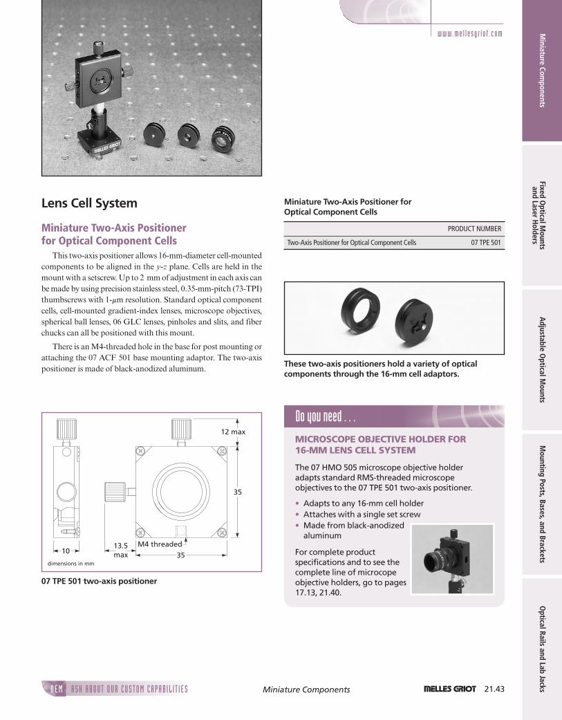
Lens Cell System
Miniature Two-Axis Positionerfor Optical Component Cells
This two-axis positioner allows 16-mm-diameter cell-mountedcomponents to be aligned in the y-z plane. Cells are held in themount with a setscrew. Up to 2 mm of adjustment in each axis canbe made by using precision stainless steel, 0.35-mm-pitch (73-TPI)thumbscrews with 1-mm resolution. Standard optical componentcells, cell-mounted gradient-index lenses, microscope objectives,spherical ball lenses, 06 GLC lenses, pinholes and slits, and fiberchucks can all be positioned with this mount.
There is an M4-threaded hole in the base for post mounting orattaching the 07 ACF 501 base mounting adaptor. The two-axispositioner is made of black-anodized aluminum.
Do you need . . .MICROSCOPE OBJECTIVE HOLDER FOR16-MM LENS CELL SYSTEM
The 07 HMO 505 microscope objective holderadapts standard RMS-threaded microscopeobjectives to the 07 TPE 501 two-axis positioner.
• Adapts to any 16-mm cell holder• Attaches with a single set screw• Made from black-anodized
aluminum
For complete productspecifications and to see thecomplete line of microcopeobjective holders, go to pages17.13, 21.40.
1013.5max 35
35
12 max
M4 threaded
dimensions in mm
07 TPE 501 two-axis positioner
PRODUCT NUMBER
Two-Axis Positioner for Optical Component Cells 07 TPE 501
Miniature Two-Axis Positioner forOptical Component Cells
These two-axis positioners hold a variety of opticalcomponents through the 16-mm cell adaptors.
21ch_MiniatureComponents_f_v3.qxd 6/8/2005 10:46 AM Page 21.43
21.44 1 A S K A B O U T O U R C U S T O M C A P A B I L I T I E SO E MMiniature Components
Min
iatu
re C
ompo
nent
sFi
xed
Opt
ical
Mou
nts
and
Lase
r H
olde
rsA
djus
tabl
e O
ptic
al M
ount
sM
ount
ing
Post
s, B
ases
, and
Bra
cket
sO
ptic
al R
ails
and
Lab
Jack
s
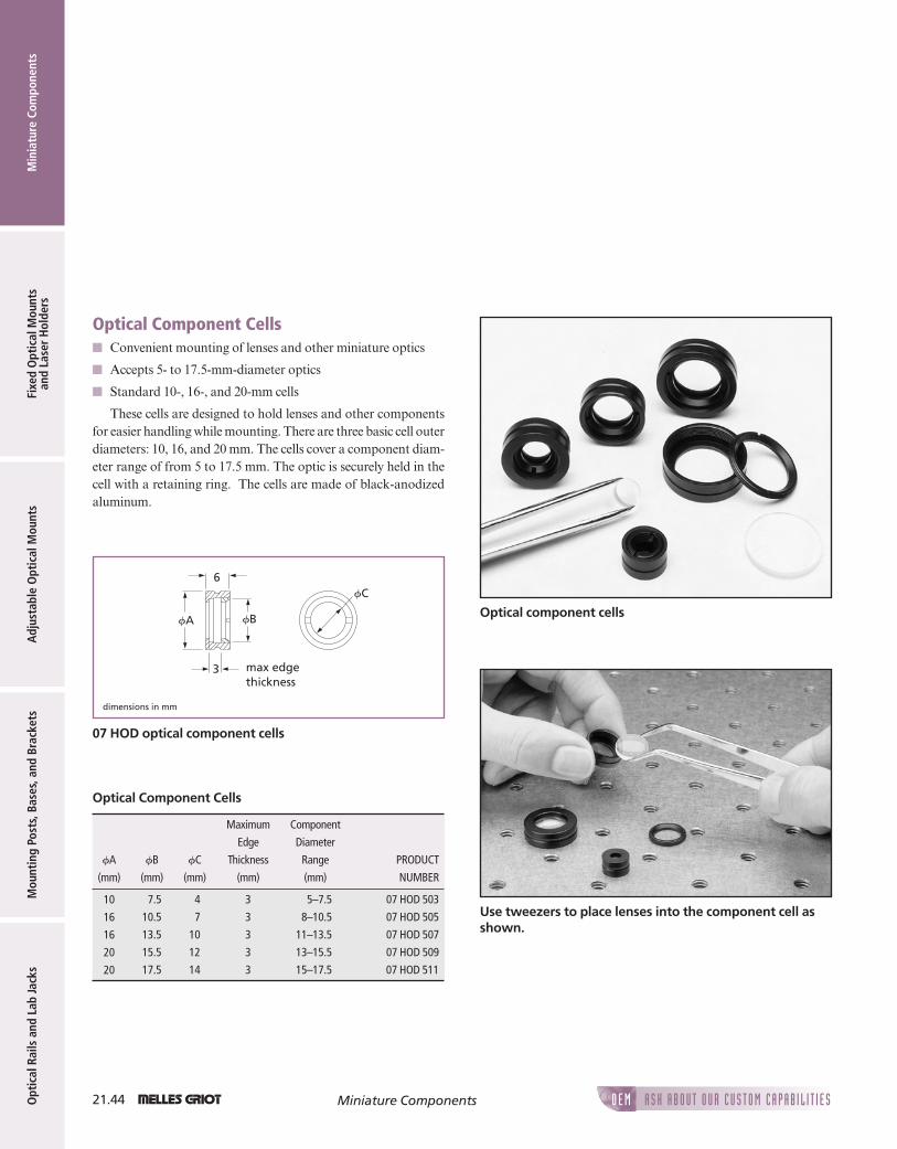
Optical Component Cells$ Convenient mounting of lenses and other miniature optics
$ Accepts 5- to 17.5-mm-diameter optics
$ Standard 10-, 16-, and 20-mm cells
These cells are designed to hold lenses and other componentsfor easier handling while mounting. There are three basic cell outerdiameters: 10, 16, and 20 mm. The cells cover a component diam-eter range of from 5 to 17.5 mm. The optic is securely held in thecell with a retaining ring. The cells are made of black-anodizedaluminum.
3
fC6
fA fB
dimensions in mm
max edgethickness
07 HOD optical component cells
Maximum Component
Edge Diameter
fA fB fC Thickness Range PRODUCT
(mm) (mm) (mm) (mm) (mm) NUMBER
7.5 4 3 5–7.5 07 HOD 503
10.5 7 3 8–10.5 07 HOD 505
13.5 10 3 11–13.5 07 HOD 507
15.5 12 3 13–15.5 07 HOD 509
17.5 14 3 15–17.5 07 HOD 511
10
16
16
20
20
Optical Component Cells
Optical component cells
Use tweezers to place lenses into the component cell asshown.
21ch_MiniatureComponents_f_v3.qxd 6/8/2005 10:46 AM Page 21.44

1 21.45A S K A B O U T O U R C U S T O M C A P A B I L I T I E SO E M
Miniature Com
ponentsFixed O
ptical Mounts
and Laser Holders
Adjustable O
ptical Mounts
Mounting Posts, Bases, and Brackets
Optical Rails and Lab JacksMiniature Components
Fiber-Chuck HolderWith this holder, fiber chucks can be mounted into any
16-mm-diameter cell holder. The fiber chuck is firmly held in thedouble-bored hole with a setscrew. The fiber-chuck holder is madeof black-anodized aluminum.
10
14
f15.95
f6.4 thru
M3 setscrew
3
dimensions in mm
07 HFC 507 fiber-chuck holder
Spherical Ball Lens Holders The spherical ball lens holders are designed to be mounted in
16-mm cell holders. Once mounted, the lenses can be aligned usingthe 07 TPE 501 two-axis positioner. Three mounts are offered, onefor each size of ball lens (2, 3, and 5 mm). The ball lenses are securelyheld in the cell with a retaining ring. The ball protrudes from oneside of the mount allowing close access to the lens. The sphericalball lens holders are made of black-anodized aluminum.
6
f16
dimensions in mm
07 HCS spherical ball lens holder
Fiber-chuck holder shown with 17 HFC 005 fiber chuck Spherical ball lens holders
PRODUCT NUMBER
Fiber-Chuck Holder 07 HFC 507
Fiber-Chuck Holder Sphere Diameter
(mm) PRODUCT NUMBER
2 07 HCS 505
3 07 HCS 507
5 07 HCS 509
Spherical Ball Lens Holders
21ch_MiniatureComponents_f_v3.qxd 6/8/2005 10:46 AM Page 21.45

21.46 1 A S K A B O U T O U R C U S T O M C A P A B I L I T I E SO E MMiniature Components
Min
iatu
re C
ompo
nent
sFi
xed
Opt
ical
Mou
nts
and
Lase
r H
olde
rsA
djus
tabl
e O
ptic
al M
ount
sM
ount
ing
Post
s, B
ases
, and
Bra
cket
sO
ptic
al R
ails
and
Lab
Jack
s
Lens Holders for 06 GLC Lenses The 06 GLC collimating and focusing lenses, described on
pages 7.27-7.29 are either 8.71 or 14.29 mm in diameter. The07 HGC 501 and 503 lens holders adapt these lenses for mountingin a 16-mm cell holder. Once mounted, the lens can be aligned usingthe 07 TPE 501 two-axis positioner (go to pages 21.43, 23.6). The07 HGC 003 lens holder is designed for mounting in a microscopeobjective lens holder. Both types of holders are made ofblack-anodized aluminum.
07 HGC 50307 HGC 501
f8.71 6
f16
f14.29
dimensions in mm
Lens holders for 16-mm cell holders
RMS thread (.8 inch-36 TPI)
25.6
f12.39
f28.6
14.810
M6!1.01/4-20
dimensions in mm
f14.29
07 HGC 003 lens holder with RMS mounting thread
Lens holders for 06 GLC lenses
PRODUCT
Description NUMBER
16-mm Cell Holders 07 HGC 501
16-mm Cell Holders 07 HGC 503
For Microscope Objective Holders 07 HGC 003
Lens Holders for 06 GLC Lenses
Do you need . . .MICROSCOPE OBJECTIVE HOLDER FOR16-MM LENS CELL SYSTEM
The 07 HMO 505 microscope objective holderadapts standard RMS-threaded microscopeobjectives to the 07 TPE 501 two-axis positioner.
• Adapts to any 16-mm cell holder• Attaches with a single set screw• Made from
black-anodizedaluminum
For complete productspecifications and tosee the completeline of microcopeobjective holders, goto pages 17.13, 21.40.
21ch_MiniatureComponents_f_v3.qxd 6/8/2005 10:47 AM Page 21.46

1 21.47A S K A B O U T O U R C U S T O M C A P A B I L I T I E SO E M
Miniature Com
ponentsFixed O
ptical Mounts
and Laser Holders
Adjustable O
ptical Mounts
Mounting Posts, Bases, and Brackets
Optical Rails and Lab JacksMiniature Components
Pinhole/Slit Holder Unmounted 9.5-mm-diameter precision pinholes or slits can
be mounted in this 16-mm-diameter cell. Once mounted, pinholesand slits are much easier to handle and can be aligned using the 07 TPE 501 two-axis positioner described on pages 21.43, 23.6.
The pinhole or slit is placed between two nylon washers whichare held in the mount by a retaining ring. The pinhole/slit holderis made of black-anodized aluminum.
6
f4 f9.5f16
dimensions in mm
07 HPI 501 pinhole/slit holder
Pinhole/slit holder
Mounted pinholes can be held using the 07 HPH 001pinhole/slit positioner.
PRODUCT NUMBER
Pinhole/Slit Holder 07 HPI 501
Pinhole/Slit Holder
Do you need . . .PRECISION PINHOLES AND SLITS
Melles Griot offers a wide selection of mountedand unmounted precision pinholes and slits. Thepinholes and slits are all laser milled in ultrathin9.5-mm-diameter stainless steel substrates.
• 04 PIP-series pinholes range from 1 mm to 1 mmin diameter.
• 04 PAS-series slitsrange from 5 to200 mm in widthand are 3 mm long.
• High-energy laserpinholes are alsoavailable.
For more informationgo to page 18.2.
21ch_MiniatureComponents_f_v3.qxd 6/8/2005 10:47 AM Page 21.47

21.48 1 A S K A B O U T O U R C U S T O M C A P A B I L I T I E SO E MMiniature Components
Min
iatu
re C
ompo
nent
sFi
xed
Opt
ical
Mou
nts
and
Lase
r H
olde
rsA
djus
tabl
e O
ptic
al M
ount
sM
ount
ing
Post
s, B
ases
, and
Bra
cket
sO
ptic
al R
ails
and
Lab
Jack
s
Gradient-Index Lens Holders The 07 HGH 501 gradient-index lens holder is designed to be
mounted in 16-mm cell holders such as 07 TPE 501. The lens isclamped in a removable nylon V-groove by a setscrew that pushesagainst a nylon pad. Two V-grooves are supplied, one for 1-mmlenses and the other for 1.8- to 2-mm lenses. The 07 HGI 505 lensholder has an integral base and a small V-groove with a stainlesssteel spring clip to hold the lens. 07 HGI 021 is a post-mountablegradient-index lens holder with an M6 mounting thread. Thisholder, with a twist of the thumbscrew, clamps the lens between aV-groove and a nylon rod.
7f2 maxf1 min
f16
6
dimensions in mm
07 HGH 501 gradient-index lens holder for 16-mm cellholders
2520
12.52.5
10
2 holesf2.5 thru
f2 maxf1 min
dimensions in mm
07 HGI 505 gradient-index lens holder with integral base
dimensions in mm
15
40
M6 threaded 10
8
3
19.8
45 deg
07 HGI 021 post mountable gradient-index lens holder
The family of gradient-index lens holders
PRODUCT NUMBER
For 16-mm Cell Holders 07 HGH 501
Spring Clip with Integral Base 07 HGI 505
Post Mountable, M6 thread 07 HGI 021
Gradient-Index Lens Holders
21ch_MiniatureComponents_f_v3.qxd 6/8/2005 10:47 AM Page 21.48

1 21.49A S K A B O U T O U R C U S T O M C A P A B I L I T I E SO E M
Miniature Com
ponentsFixed O
ptical Mounts
and Laser Holders
Adjustable O
ptical Mounts
Mounting Posts, Bases, and Brackets
Optical Rails and Lab JacksMiniature Components
Iris Diaphragms These two iris diaphragms mount in the 07 HOC-series side-
loading cell holders (go to page 21.50). The 04 IDC 000 irisdiaphragm, which is 14.8 mm in diameter, requires an 07 HID 507adaptor ring to be able to mount in the 16-mm cell holders. Theadaptor ring has a slot to enable adjustment of the actuating pin.The 04 IDC 001 iris diaphragm mounts directly into 20-mm cellholders.
dimensions in mm
04 IDC 000 07 HID 507
f14.8
f16
6
f8max
f0.8min
f14.8 4.5
f14.8
6
f16
04 IDC 000 iris diaphragm and 07 HID 507 adaptor ring for16-mm cell holders
dimensions in mm
5
f19.8
11f0.9min.
f12max
04 IDC 001 iris diaphragm for 20-mm cell holders
Iris diaphragms and adaptor ring
PRODUCT NUMBER
Iris Diaphragm for 16-mm cell holders 04 IDC 000
Iris Diaphragm for 20-mm cell holders 04 IDC 001
Adaptor Ring for 04 IDC 000 (fits 16-mm cell holders) 07 HID 507
Iris Diaphragms
Pinholes
Pinholes can be used in place of iris diaphragms ifsmaller diameter apertures are needed.
APPLICATION NOTE
21ch_MiniatureComponents_f_v3.qxd 6/8/2005 10:47 AM Page 21.49

21.50 1 A S K A B O U T O U R C U S T O M C A P A B I L I T I E SO E MMiniature Components
Min
iatu
re C
ompo
nent
sFi
xed
Opt
ical
Mou
nts
and
Lase
r H
olde
rsA
djus
tabl
e O
ptic
al M
ount
sM
ount
ing
Post
s, B
ases
, and
Bra
cket
sO
ptic
al R
ails
and
Lab
Jack
s
Cell Holders There are two types of cell holders: post mount and side-load-
ing. Both are available for 10-, 16-, and 20-mm cells. The 16-mm,side-loading holders are offered in two heights: 10 and 15 mm. Allhave a central M2-threaded hole for post mounting. They are allmade of black-anodized aluminum.
These holders provide fixed mounting for any of thecomponent cells.
dimensions in mm
2025
3.5 20
26
13.5
12.5
6
3
12.5
fA
3 holes f2.4 thrucounterbored f4.4!2.2 deep
1 holethreaded M2 thru(510 is 3 deep)
07 MEA-series cell holders
fA PRODUCT
(mm) NUMBER
10 07 MEA 510
16 07 MEA 511
20 07 MEA 512
Standard Cell Holders
20
D
2 holesf2.5 thru
1 hole threaded M2(except 07 HOC 505)
6
AC
B
25
dimensions in mm
07 HOC-series side-loading cell holders
A B C D PRODUCT
(mm) (mm) (mm) (mm) NUMBER
10 10 15.0 18.0 07 HOC 501
16 10 17.5 20.0 07 HOC 505
16 15 17.5 25.0 07 HOC 507
20 15 22.5 27.5 07 HOC 509
Side-Loading Cell Holders
21ch_MiniatureComponents_f_v3.qxd 6/8/2005 10:47 AM Page 21.50