2.13 Microfluidic for Lab-on-a-Chip - Elsevier...fluidics (Microfluidics and Nanofluidics, Springer)...
54
ELSEVIER SECOND PROOF 2.13 a0005 Microfluidic for Lab-on-a-Chip Stefan Haeberle 1,2 and Roland Zengerle 1,2 , 1 Institute for Micromachining and Information Technology of the Hahn-Schickard-Society (HSG-IMIT), Villingen-Schwenningen, Germany, 2 Laboratory for MEMS Applications, Department of Microsystems Engineering (IMTEK), University of Freiburg, Freiburg, Germany ª 2007 Elsevier Ltd. All rights reserved. 2.13.1 Introduction 3 2.13.1.1 Microfluidics 3 2.13.1.2 Microfluidics – An Enabling Technology 4 2.13.1.3 The Need for Microfluidic Platforms 4 2.13.1.4 Discrete Solutions for Unique Technical Challenges 5 2.13.1.5 What Is a Microfluidic Platform? 5 2.13.1.6 Overview of the Following Chapters 6 2.13.2 Capillary-driven Test Strips (Lateral Flow Assays) 7 2.13.2.1 Introduction 7 2.13.2.1.1 About capillary forces 8 2.13.2.2 Unit Operations Controlled by Capillary Forces 8 2.13.2.2.1 Sample loading 8 2.13.2.2.2 Separation 8 2.13.2.2.3 Transport 8 2.13.2.2.4 Incubation 9 2.13.2.2.5 Mixing 9 2.13.2.2.6 Metering 9 2.13.2.2.7 Amplification 10 2.13.2.2.8 Readout 10 2.13.2.3 Application Example: The Cardiac Ò Reader 10 2.13.2.4 Strengths and Challenges of the Platform 11 2.13.3 Pressure-driven Systems 11 2.13.3.1 One Step Forward in Controllability and Complexity 11 2.13.3.2 Unit Operations in Pressure-driven Microfluidics 11 2.13.3.2.1 Fluid transport (Laminar flow) 11 2.13.3.2.2 Valving 14 2.13.3.2.3 Mixing 14 2.13.3.2.4 Metering 15 2.13.3.2.5 Switching 15 2.13.3.2.6 Separation 15 2.13.3.3 Application Examples 17 2.13.3.3.1 Portable handheld analyzer: i-STAT Ò 17 2.13.3.3.2 Diffusion-based assays: T-Sensor Ò 18 2.13.3.4 Strength and Challenges of the Platform 18 2.13.4 Microfluidic Large-scale Integration 19 2.13.4.1 Introduction 19 2.13.4.1.1 PDMS – Soft lithography 19 2.13.4.2 Microfluidic Large-scale Integration: Unit Operations 19 2.13.4.2.1 Valving 19 2.13.4.2.2 Pumps and mixers 20 2.13.4.2.3 Multiplexing 21 2.13.4.2.4 Metering 21 MEMS 00038 1
Transcript of 2.13 Microfluidic for Lab-on-a-Chip - Elsevier...fluidics (Microfluidics and Nanofluidics, Springer)...

ELS
EVIE
RSEC
ON
DPR
OO
F
2.13a0005 Microfluidic for Lab-on-a-ChipStefan Haeberle1,2 and Roland Zengerle1,2, 1Institute for Micromachining and Information Technology ofthe Hahn-Schickard-Society (HSG-IMIT), Villingen-Schwenningen, Germany, 2Laboratory for MEMSApplications, Department of Microsystems Engineering (IMTEK), University of Freiburg, Freiburg, Germany
ª 2007 Elsevier Ltd. All rights reserved.
2.13.1 Introduction 3
2.13.1.1 Microfluidics 3
2.13.1.2 Microfluidics – An Enabling Technology 4
2.13.1.3 The Need for Microfluidic Platforms 4
2.13.1.4 Discrete Solutions for Unique Technical Challenges 5
2.13.1.5 What Is a Microfluidic Platform? 5
2.13.1.6 Overview of the Following Chapters 6
2.13.2 Capillary-driven Test Strips (Lateral Flow Assays) 7
2.13.2.1 Introduction 7
2.13.2.1.1 About capillary forces 8
2.13.2.2 Unit Operations Controlled by Capillary Forces 8
2.13.2.2.1 Sample loading 8
2.13.2.2.2 Separation 8
2.13.2.2.3 Transport 8
2.13.2.2.4 Incubation 9
2.13.2.2.5 Mixing 9
2.13.2.2.6 Metering 9
2.13.2.2.7 Amplification 10
2.13.2.2.8 Readout 10
2.13.2.3 Application Example: The Cardiac� Reader 10
2.13.2.4 Strengths and Challenges of the Platform 11
2.13.3 Pressure-driven Systems 11
2.13.3.1 One Step Forward in Controllability and Complexity 11
2.13.3.2 Unit Operations in Pressure-driven Microfluidics 11
2.13.3.2.1 Fluid transport (Laminar flow) 11
2.13.3.2.2 Valving 14
2.13.3.2.3 Mixing 14
2.13.3.2.4 Metering 15
2.13.3.2.5 Switching 15
2.13.3.2.6 Separation 15
2.13.3.3 Application Examples 17
2.13.3.3.1 Portable handheld analyzer: i-STAT� 17
2.13.3.3.2 Diffusion-based assays: T-Sensor� 18
2.13.3.4 Strength and Challenges of the Platform 18
2.13.4 Microfluidic Large-scale Integration 19
2.13.4.1 Introduction 19
2.13.4.1.1 PDMS – Soft lithography 19
2.13.4.2 Microfluidic Large-scale Integration: Unit Operations 19
2.13.4.2.1 Valving 19
2.13.4.2.2 Pumps and mixers 20
2.13.4.2.3 Multiplexing 21
2.13.4.2.4 Metering 21
MEMS 00038
1
ELS
EVIE
RSEC
ON
DPR
OO
F
2.13.4.3 Application Examples 22
2.13.4.3.1 Protein crystallization 22
2.13.4.3.2 Nucleic acid isolation 23
2.13.4.4 Strength and Challenges of the Platform 25
2.13.5 Centrifugal Microfluidics 25
2.13.5.1 Introduction to the Lab-on-a-Disk Approach 26
2.13.5.2 Microfluidic Unit Operations on the Centrifugal Platform 27
2.13.5.2.1 Fluid transport 27
2.13.5.2.2 Valving 27
2.13.5.2.3 Metering and aliquotting 28
2.13.5.2.4 Mixing 29
2.13.5.2.5 Switching 29
2.13.5.2.6 Droplet formation 30
2.13.5.2.7 Separation 31
2.13.5.3 Application Examples 32
2.13.5.3.1 Blood test (Abaxis Picolo�) 32
2.13.5.3.2 Enzyme-linked immunosorbent assay (LabCD) 32
2.13.5.3.3 Protein quantification (Gyrolab Bioaffy�) 33
2.13.5.3.4 Alcohol test (Bio-Disk) 34
2.13.5.4 Strengths and Challenges of the Platform 34
2.13.6 Droplet-based Microfluidic Platforms 35
2.13.6.1 Introduction 35
2.13.6.2 Pressure-driven Unit Operations 35
2.13.6.2.1 Basic set-up 35
2.13.6.2.2 Droplet generation and metering 36
2.13.6.2.3 Sample load 36
2.13.6.2.4 Merging and splitting of droplets 37
2.13.6.2.5 Transport 37
2.13.6.2.6 Mixing 37
2.13.6.2.7 Incubation 38
2.13.6.2.8 Switching 38
2.13.6.2.9 Application example: protein crystallization 38
2.13.6.3 Electrowetting-driven Unit Operations 39
2.13.6.3.1 Basic set-up 39
2.13.6.3.2 Metering 40
2.13.6.3.3 Mixing 41
2.13.6.3.4 Merging and splitting of droplets 41
2.13.6.3.5 Readout 41
2.13.6.4 SAW-driven Unit Operations 42
2.13.6.4.1 Basic set-up 42
2.13.6.4.2 Metering 43
2.13.6.4.3 Mixing 44
2.13.6.4.4 Merging and splitting of droplets 44
2.13.6.4.5 Incubation and entrapment 44
2.13.6.4.6 Readout 44
2.13.6.5 Strengths and Challenges of the Platform 44
2.13.7 Free Scalable Noncontact Dispensing 45
2.13.7.1 Introduction and Motivation 45
2.13.7.2 Unit Operations 45
2.13.7.2.1 Metered dispensing 45
2.13.7.2.2 Incubation 47
2.13.7.2.3 Amplification 47
MEMS 00038
2 Microfluidic for Lab-on-a-Chip

ELS
EVIE
RSEC
ON
DPR
OO
F
2.13.7.3 Application Examples 47
2.13.7.3.1 TopSpot for microarray spotting 47
2.13.7.3.2 Dispensing well plate 48
2.13.7.4 Strengths and Challenges of the Platform 49
2.13.8 Conclusion 49
References 49
Glossaryg9000 CMOS Complementary Metal Oxide
Semiconductor
g9005 DWP Dispensing Well Plate
g9010 EDC/NHS Carbodiimid/N-hydroxysuccinimide
g9015 EOF Electroosmotic Flow
g9020 EP Electrophoresis
g9025 EWOD Electrowetting
g9030 FID Free Interface Diffusion
g9035 GC Gas Chromatograph
g9040 HPLC High Pressure Liquid Chromatograph
g9045HTS High Throughput Screening
g9050IDT Interdigital Transducer
g9055LSI (microfluidic) Large Scale Integration
g9060MSL Multilayer Soft Lithography
g9065PCR Polymerase Chain Reaction
g9070PDMS Polydimethylsiloxane
g9075SAW Surface Acoustic Wave
g9080TAS Total Chemical-analysis System
g9085TIR Total Internal Reflection
g9090mTAS micro Total Analysis System
s0005 2.13.1 Introduction
s0010 2.13.1.1 Microfluidics
p0005 The history of microfluidics dates back to the early1950s when efforts to dispense small amounts ofliquids in the nano- and subnanoliter range weremade for providing the basics of today’s ink-jet tech-nology (
b0435
Le 1998). In terms of fluid propulsion withinmicrochannels of submillimeters cross-section, theyear 1979 set a milestone when a miniaturized gaschromatograph (GC) was realized on a silicon wafer(
b0765
Terry et al. 1979). The first high-pressure liquidchromatography (HPLC) column device, fabricatedusing Si-Pyrex technology, was published by
b0500
Manzet al. (1990b). By the end of the 1980s the first micro-valves (
b0665
Shoji et al. 1988) and micropumps (b0800
Van Lintelet al. 1988) based on silicon micromachining were alsopresented. All these examples represent microfluidicsystems since they enable the precise control of thedecreasing fluid volumes on the one hand and theminiaturization of the size of a fluid handling systemon the other hand.
p0010 Another important aspect of microfluidics is theexploitation of effects and phenomena that can beutilized only in microdimensions. Smaller channeldimensions drastically increase the surface-to-volumeratio and thus surface-related phenomena like laminar
flow, capillarity, fast thermal response, and electroki-netics gain influence. This can be used in microfluidicsystems to enhance the performance of analytical proce-dures.
b0495
Manz et al. (1990a) also proposed the concept ofminiaturized total chemical analysis systems (TAS)based on the unique conditions in the microdomain.Today this approach is also known as micro totalanalysis systems (�TAS) or laboratories on a chip (lab-on-a-chip) as proposed by
b0310
Harrison et al. (1992).p0015Following this �TAS or lab-on-a-chip approach,
the first applications that emerged in the field of ana-lytical chemistry were based on the electro-osmoticflow (EOF) to pump liquids into small microcapillariesand on electrophoretic separation (EP) to distinguishsample components (
b0155
Effenhauser et al. 1993,b0310
Harrisonet al. 1992,
b0315
1993,b0505
Manz et al. 1992). These developmentsin the early 1990s drastically increased the academicand commercial interest in microfluidic technologies.This trend continues to the present day, as described ina recent comment on the proliferation of microfluidicsin literature and intellectual property, which claimsthat 581 of 770 microelectromechanical systems(MEMS)-related papers published in 2003 dealt withmicrofluidics (
b0390
Kamholz 2004).p0020So down to the present day manifold lab-on-a-
chip systems have been developed for diverse appli-cations, e.g., for DNA analysis (
b0065
Burns et al. 1998),
MEMS 00038
Microfluidic for Lab-on-a-Chip 3

ELS
EVIE
RSEC
ON
DPR
OO
F
DNA amplification (polymerase chain reaction,PCR) (
b0120
deMello 2003,b0420
Kopp et al. 1998), proteomics(
b0470
Lion et al. 2003,b0520
Marko-Varga et al. 2003), samplepretreatment (
b0530
de Mello and Beard 2003). Recentgeneral reviews on the whole field of lab-on-a-chipsystems can be found in
b0035
Auroux et al. (2002),b0615
Reyeset al. (2002), and
b0805
Vilkner et al. (2004). The enormousimpact of microfluidic lab-on-a-chip technologiesalso becomes obvious by the large number of recentlypublished books. They either cover the whole field ofmicrofluidics (
b0460
Li 2006,b0550
Nguyen and Wereley 2002)or focus on the engineering (
b0220
Geschke et al. 2004)or applications of microfluidic systems (
b0025
Anderssonand van den Berg 2004,
b0575
Oosterbroek and van denBerg 2003,
b0760
Tay 2002,b0790
Urban 2006). Also journalsexclusively dedicated to the field of micro- and nano-fluidics (Microfluidics and Nanofluidics, Springer) orlab-on-a-chip systems (Lab on a Chip, Royal Societyof Chemistry) have been published recently.
s0015 2.13.1.2 Microfluidics – An EnablingTechnology
p0025 From a more business-related point of view, it can bestated that nowadays most MEMS-related technol-ogy roadmaps and market studies point out thesignificant technological and scientific impact thatmicrofluidics will have on various industries, espe-cially the life sciences. A dedicated microfluidicsroadmap was prepared by
b0130
Ducree and Zengerle(2004). In this study the economic developmentrelated to microfluidics technologies for the lifesciences has been estimated and important marketdrivers and road blocks have been pinpointed.
p0030 Regarding the economic impact of microfluidics,the study anticipates an overall growth rate ofmore than 30% per annum for microfluidic tech-nologies and products in the life sciences. Drugdiscovery, medical diagnostics, and therapeuticdevices represent the most promising fields. Theoverall global market of microfluidics in the lifesciences has been estimated to be worth approxi-mately 500 million euros in 2002, increasing withan assumed annual growth rate of 19% to 1.4 billioneuros in 2008.
p0035 Besides the economic impact of microfluidics,technological trends have also been clearly identifiedin the roadmap. Amongst those the most relevant isthe need for microfluidic platforms equipped with abasic set of validated fluidic base operations to arriverapidly at application-specific microfluidic systems.This system-oriented platform concept contrasts
the frequent approaches in which components suchas pumps or valves have been optimized at anindividual level and assembled afterward.
s00202.13.1.3 The Need for MicrofluidicPlatforms
p0040Why are microfluidic platforms needed? As describedin Section 2.13.1.1 the impact of microfluidic technol-ogies in the academic world has dramaticallyincreased during the last few years. This is quiteamazing since microfluidics is no independent productconsumers want to buy. Microfluidics should bemerely considered as a toolbox, which is needed todevelop innovative new products in such disparatefields as medical, pharmaceutical, and analytical appli-cations. As a consequence, the most importantcustomer for microfluidic know-how and technologiesis the research community itself, which develops newproducts and solutions in the different applicationareas such as the biotechnology, diagnostics, medical,or pharmaceutical industry.
p0045During the last two decades, thousands ofresearchers have spent a lot of time developing newmicrofluidic components or exploring the basicmicrofluidic operations such as fluid transport, fluidmetering, fluid mixing, valving or concentration, andseparation of molecules within miniaturized quanti-ties of fluids. Today hundreds of different types ofmicropumps have been fabricated (
b0430
Laser andSantiago 2004), hundreds of different types of mixersand hundreds of different types of microvalves areknown, and almost no standards are defined in termsof interconnections. It seems to be the right time toraise the question of whether we really need moreof those components? On the basis of our experiencein the lab-on-a-chip field, a component-based micro-fluidic approach is much too slow and the R&D effortis much too expensive to explore the huge potentialof different applications. In addition, the best perfor-mance you can get out of such a component-orientedsolution will be far behind what you can get in anintegrated system approach, or in other words in amicrofluidic platform approach. Therefore we thinkthat the described practice of assembling discretecomponents such as valves and pumps, at least inthe field of lab-on-a-chip applications, belongs tothe past and we do not expect it to continue in thefuture. In our view the research community reallyneeds validated and easy-to-operate microfluidicplatforms. They have to offer an adequate numberof microfluidic operations that can be easily
MEMS 00038
4 Microfluidic for Lab-on-a-Chip

ELS
EVIE
RSEC
ON
DPR
OO
F
combined to build application-specific microfluidicsystems. In addition these systems should be fabri-cated using a standardized cost-efficient technology.
s0025 2.13.1.4 Discrete Solutions for UniqueTechnical Challenges
p0050 Before pointing out the advantages of the microflu-idic platform concept, we describe the opposite: twoexamples of application-specific integrated systems,which represent unique engineering solutions forunique technical problems. The electronic fountainpen (
b0810
Waibel et al. 2003) as depicted in Figure 1 is agood example of such a discrete microfluidic solu-tion. It can be regarded as the first fully functional,highly integrated, miniaturized, and self-sustainingmicrodosage system of its kind operating underreal-world conditions. The main components are aliquid level sensor, a microvalve, and a bubble- andparticle-tolerant fluidic system. The pen is optimizedwith respect to minimum energy consumption. Itcontains a programmable ASIC and is powered bytwo standard watch batteries ensuring operation overa period of 2 years under standard conditions.
p0055 The oral drug delivery system (Figure 2),currently under development at HSG-IMIT, is asimilar example (
b0225
Goettsche and Wolff 2006). It hasthe size of two buccal teeth and will be integratedinto the human denture. It consists of a drug reservoircapable of incorporating a solid pill, an osmotic pump,and a flow sensor. The refillable system is loaded by asolid pill and is designed to deliver liquid drug over aperiod of 2 weeks at rather harsh ambient conditions
(mechanical loads, wide temperature range, and con-tact with any kind of food) inside the human mouth.
p0060Both microfluidic systems perfectly fulfill therequirements for their specific applications.However, for any other application in the field ofmicrodosage or more general in the field of micro-fluidics, the specific know-how from developingsuch a system is only of very limited value andevery development of this kind always starts fromthe scratch again. This causes significant costs andtime at a high economic risk. Although we expectthis kind of development to make sense for a fewselected applications in diverse fields of applicationsin the future also, it is quite clear that this approachwill not succeed for lab-on-a-chip systems or thediagnostic applications that are dealt with in thischapter.
s00302.13.1.5 What Is a Microfluidic Platform?
p0065Very similar to the ASIC industry in microelectronics,which provides validated elements and processes tomake electronic circuits, a dedicated microfluidic plat-form comprises a reduced set of validated microfluidicelements. These elements are capable of performingthe basic fluidic unit operations required in a givenapplication area. Such basic fluidic unit operationsare, for example, fluid transport, fluid metering, fluidmixing, valving, and separation or concentration ofmolecules or particles. The collection of fluidic unitoperations needed for diagnostic applications can haveonly little overlap with the collection needed for phar-maceutical applications or for applications inmicroreaction technology. In some cases detectionmethods also belong to the basic set of microfluidic
Photo transistor(system activation)
Nib
Ink-level sensor
Controlelectronics
Ink cartridge
Figure 1f0005 Photo of the electronic fountain pen(145 mm� 12 mm). (Reprinted with permission from Waibel
G, Kohnle J, Cernosa R, Storz M, Schmitt M, Ernst H,
Sandmaier H, Zengerle R, Strobelt T 2003 Highly integrated
autonomous microdosage system. Sens. Actuators A Phys.103, 225–30. Copyright 2003 Elsevier.)
1
Figure 2 f0010Photo of a drug delivery system that can
be implanted into a human denture. (Source: Goettsche T,
Wolff, A 2006 IntelliDrug – An integrated intelligentoral drug delivery system. mst-news 06, 36–7.)
MEMS 00038
Microfluidic for Lab-on-a-Chip 5

ELS
EVIE
RSEC
ON
DPR
OO
F
operations, and in other cases this is not the case(Table 1). Nevertheless, in all cases the user of a plat-form should be capable of readily combining theelements within a given platform in order to implementan assay for diagnostic applications or to screen for newcompounds in pharmaceutical applications. Often, anefficient development is intimately linked to the avail-ability of (standard) test setups and simulation tools.
p0070 More important than providing a totally completeset of fluidic unit operations in a platform is the fact thatall elements have to be amenable to a well-establishedfabrication technology. Furthermore all elements ormodules of a platform have to be connectible, ideallyin a monolithically integrated way or at least by a well-defined, ready-to-use interconnection and packagingprocess. If a platform allows a seamless and simpleintegration of different fluidic elements in a monolithicway, for example, without sophisticated additionalpackaging techniques, this provides a significant advan-tage compared to other platforms. Thus speaking aboutmicrofluidic platforms also involves at least one vali-dated fabrication technology to realize completesystems out of the elements. This results in a definitionof a platform as follows.
p0075 A microfluidic platform allows to perform a set offluidic unit operations that are enabled by a set offluidic elements, which are designed for easy combi-nation with a well-defined (and low-cost) fabricationtechnology. The platform allows to implement andfabricate different application-specific solutions in aneasy and flexible way.
s0035 2.13.1.6 Overview of the FollowingChapters
p0080 When comparing microfluidic platforms with themicroelectronics industry, the question of whether wereally need a diverse set of different microfluidic
platforms arises. The coexistence of different platformsand their specific fabrication technologies could be
regarded as a drawback since R&D efforts go in manydirections and cannot be focused exclusively on one
technology (as is complementary metal oxide semicon-ductor (CMOS) in microelectronics). On the otherhand, the diversity of approaches and technologies
can be considered as an advantage for their successfuladoption in different application fields. Owing to the
diversity, specific advantages of certain platforms arelikely to succeed in different application areas. It is,however, essential that a specific platform provides all
of the characteristic features given in Table 1.p0085This chapter is intended to give an overview of
microfluidic platforms that have been developed until
today. We will thereby focus only on platforms forlab-on-a-chip application, being aware that there are
also other possible fields of applications for microflui-dic platforms such as microprocess engineering ormicrodosage systems. However, in the field of
lab-on-a-chip systems also, we cannot cover all micro-fluidic platforms, which are known from literature.
Prominent examples of platforms that will not bediscussed here are certainly the electrokinetic plat-form (EOF, EP), the microarray platform, and the
microwell plate technology platform. These platforms,however, are already well described in many scientificpapers and books. It is, furthermore, not intended to
assess the different platforms by their value to theindustry or to the research community.
p0090As is evident in the introduction, the scope of thischapter is not to describe single microfluidic compo-nents. For detailed reviews on single components such
as micropumps (b0230
Gravesen et al. 1993,b0430
Laser andSantiago 2004,
b0660
Shoji and Esashi 1994,b0835
Woias 2005),
valves (b0565
Oh and Ahn 2006), mixers (b0340
Hessel et al. 2005,b0555
Nguyen and Wu 2005), microfluidic technologies ingeneral (
b0700
Squires and Quake 2005,b0735
Stone et al. 2004), or
t0005 Table 1 Common features of microfluidic platforms
Microfluidic operations Fabrication technology
Validated elements for basic microfluidic unit
operations such as
Validated manufacturing technology for the whole set
of fluidic elements
� Fluid transport (prototyping and mass fabrication)� Fluid metering Seamless integration of different elements
� Fluid valving � Ideally in a monolithic way
� Fluid mixing � Or by a well-defined easy packaging technique� Separation
� Concentration
� Detection
� � � �
MEMS 00038
6 Microfluidic for Lab-on-a-Chip

ELS
EVIE
RSEC
ON
DPR
OO
F
simulation techniques for the design of lab-on-a-chipsystems (
b0180
Erickson 2005) we also refer to the publishedwork.
p0095 In the following, each microfluidic platform isdescribed in the same way. First, we motivate theplatform approach and give a short introduction onthe basic setup and functional principle. Then, themain unit operations realized on the platform and anapplication example based on their selection are pre-sented. Finally, each section closes with a discussionon the strength and the challenges of the platform aswe can see them today.
s0040 2.13.2 Capillary-driven Test Strips(Lateral Flow Assays)
s0045 2.13.2.1 Introduction
p0100 The capillary-driven test strip platform is the state ofthe art in point-of-care diagnostics, with billions ofunits that are produced in an extremely cheap man-ner. It is amazing that within the lab-on-a-chip ormicrofluidics community, not very much is knownabout this easiest way to perform assays on such aneasy to handle widely used platform (e.g., diabetestesting, pregnancy testing).
p0105 The first test strip is certainly the indicator paperfor pH measurement, which is also a representativefor the most simple assay on the capillary-driven teststrip platform. It consists only of one single fleecewith an integrated colorimetric reagent (Table 2).
The sample liquid is transported into the fleece of the
test strip by capillary forces and a color change,
depending on the pH value of the sample liquid,
occurs. This color change is initiated by a reaction
between the sample and the reactant. Starting from
that most simple point of assay format, more complex
configurations with multiple reagents or even several
fleeces enable the implementation of more complex
assays like immunoassays.p0110The so-called lateral flow assays are well known
in the diagnostic field since the 1960s. Although this
can be regarded as the most successful microfluidic
platform for lab-on-a-chip applications in terms of
applications and commercialized products, hardly
any publication from a microfluidic point of view
exists.p0115The possibility of performing an automated on-
site measurement, using a cheap and small disposable
test strip, combined with the simple actuation prin-
ciple that does not need any energy supply, gives the
platform a huge potential for point-of-care and
patient self-testing applications. Today, millions of
diabetics all over the world use these diagnostic
devices to measure their glucose concentration
several times per day and therewith adjust their
medication.p0120The basic principle of the platform is the passive
liquid transport via capillary forces within the capil-
laries of a fleece or microstructure layer. The
physical background of these actuation principle is
described in Section 2.13.2.1.1.
t0010 Table 2 Degrees of complexity and application examples on the capillary-driven test strip platform
Capillary configuration
Com
plex
ity
Application examples
Single fleece with colorimetric reactant
Indicator paper (pH measurement)
BSE test, TNT test
Pregnancy test, cardiac markers, drug test
Detection of up to 100 different proteins (immunoassays)
Single fleece with multiple reactants and colorization
Multiple fleeces with different zones of reactants, often cased
MEMS-based capillary channels, multiple complex reactions
MEMS 00038
Microfluidic for Lab-on-a-Chip 7
ELS
EVIE
RSEC
ON
DPR
OO
F
s0050 2.13.2.1.1 About capillary forces
p0125 One effect that becomes more and more importantwhen scaling down fluidic channels is the capillaryforce. A capillary pressure difference
�p� ¼2�
rcos � ½1�
appears across the liquid–gas interface with surfacetension � in a capillary of radius r and contact angle �.For hydrophilic contact angles <90� (partially wet-ting) the pressure in the liquid phase exceeds thepressure in the gas phase, leading to a further wettingof the capillary. For hydrophobic contact angles >90�
(partially nonwetting) the meniscus withdrawsrespectively.
p0130 An important effect when dealing with capillary-driven liquid flows is contact line pinning. It causesthe sudden stop of the proceeding meniscus at edgesthat represent a geometrical singularity. This has tobe taken into account when designing microfluidicstructures on the capillary test strip platform since noadditional pressure is available to overcome this stop.On the other hand, however, this mechanism can beused to control the course of capillary priming on theplatform.
s0055 2.13.2.2 Unit Operations Controlled byCapillary Forces
s0060 2.13.2.2.1 Sample loading
p0135 Several methods for sample loading exist. For biggervolumes, the sample is filled into a start reservoirfrom where it penetrates the underlying capillaries.If the sample volumes are not sufficient, the additionof a dilution buffer is sometimes required to enhanceor allow the capillary transport in the first place. Thesecond method, especially used in patient self-testingapplications, is the direct capillary filling of the strip
from the sampling point. For blood diagnostic assays,for example, the test strip is directly contacted withthe blood spilled out of the finger tip that has beenlocally pricked with a lancet before.
s00652.13.2.2.2 Separation
p0140Separation steps are required for analyzing humanwhole blood, for example, since the red blood cellswith a volume fraction >40% would interfere withthe assay. As the blood passes through a separationfleece, cells are filtered from the blood (
b0110
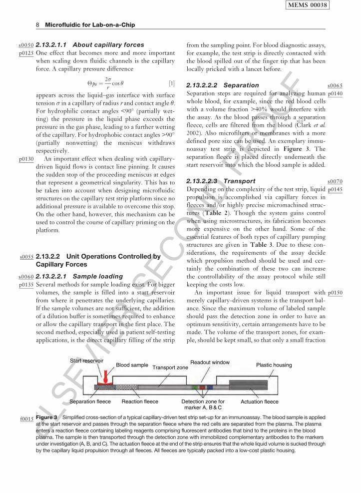
Clark et al.2002). Also microfilters or membranes with a moredefined pore size can be used. An exemplary immu-noassay test strip is depicted in Figure 3. Theseparation fleece is placed directly underneath thestart reservoir into which the blood sample is added.
s00702.13.2.2.3 Transport
p0145Depending on the complexity of the test strip, liquidpropulsion is accomplished via capillary forces infleeces and/or highly precise micromachined struc-tures (Table 2). Though the system gains controlwhen using microstructures, its fabrication becomesmore expensive on the other hand. Some of theessential features of both types of capillary pumpingstructures are given in Table 3. Due to these con-siderations, the requirements of the assay decidewhich propulsion method should be used and cer-tainly the combination of these two can increasethe controllability of the assay protocol while stillkeeping the costs low.
p0150An important issue for liquid transport withmerely capillary-driven systems is the transport bal-ance. Since the maximum volume of labeled sampleshould pass the detection zone in order to have anoptimum sensitivity, certain arrangements have to bemade. The volume of the transport zones, for exam-ple, should be kept small, so that only a small fraction
Start reservoirBlood sample
Separation fleece Reaction fleece
Transport zoneReadout window Plastic housing
Actuation fleeceDetection zone formarker A, B & C
Figure 3f0015 Simplified cross-section of a typical capillary-driven test strip set-up for an immunoassay. The blood sample is appliedat the start reservoir and passes through the separation fleece where the red cells are separated from the plasma. The plasma
enters a reaction fleece containing labeling reagents comprising fluorescent antibodies that bind to the proteins in the blood
plasma. The sample is then transported through the detection zone with immobilized complementary antibodies to the markersunder investigation (A, B, and C). The actuation fleece at the end of the strip ensures that the whole liquid volume is sucked through
by the capillary liquid propulsion through all fleeces. All fleeces are typically packed into a low-cost plastic housing.
MEMS 00038
8 Microfluidic for Lab-on-a-Chip

ELS
EVIE
RSEC
ON
DPR
OO
F
of the initial sample volume remains within that deadvolume. Another measure for a good volume balanceis to ensure that the capillarity of the input zone(separation and labeling fleece) is lower than thecapillarity of the actuation fleece, leading to a com-plete drainage of the sample into the actuation fleecebefore the liquid propulsion terminates.
p0155 A very fundamental requirement for a successfulassay is that the initially added sample volumeexceeds a critical minimum. Otherwise, the completewetting of all the essential test strip zones cannot beassured and the assay fails.
s0075 2.13.2.2.4 Incubation
p0160 During an assay protocol on the capillary-driven teststrip platform, the sample has to get in contact andreact with several predeposited reagents. They areintegrated into the fleece or microstructure of thestrip during fabrication. This is mostly done byfleeces that are saturated with the reagent and driedafterward. If needed, the reactant molecules can alsobe covalently bound to the surface using standardimmobilizing techniques like the carbodiimid(EDC)/N-hydroxysuccinimide (NHS) chemistry.
p0165 The setting of an appropriate incubation time forreagent dissolution is managed by different zoneswithin the test strip, exhibiting different wettingproperties. The basic principle behind this approachis depicted in Figure 4. First, the liquid primes thereaction chamber, where a dry reagent is predepos-ited in a pillar microstructure. This is achieved veryfast due to a low contact angle of 10� only. Thepropagation of the liquid meniscus is then sloweddown within a so-called time gate with an increasedcontact angle of � ¼ 80� and consequently a reducedcapillary force. The time for the dissolution of thedry reagent is set by the length of the time gate andends as soon as the liquid reaches the detection zonewith an increased capillary pumping force (� ¼ 10�)speeding up the flow again.
s00802.13.2.2.5 Mixing
p0170The dissolution of the preloaded dried reagent situatedin the reaction fleece, described as an incubation stepbefore, can also be regarded as a kind of mixing opera-tion. A characteristic feature of the capillary test stripplatform is the fact that mixing generally is purelypassive and is based only on diffusion. It cannot beaccelerated externally and is also one of the majordrawbacks of this kind of platform. In order to keepthe mixing time short, a high surface-to-volume ratiowithin the reaction chamber is preferred. However, thedissolution time typically still lies in the range of severalminutes and thus the capillary flow through the reac-tion chamber has to be throttled as described before.
s00852.13.2.2.6 Metering
p0175The metering of liquids is an important unit operationfor quantitative assays. Within a test strip, metering isdone by the defined volumes of the fleeces and
Reactionchamber(θ = 10°)
Time gate(θ = 80°)
Detectionzone
(θ = 10°)Flo
w
Figure 4 f0020Schematic realization of a certain incubation
time in the capillary-driven test strip platform. The liquid flow
is throttled in the time gate of reduced wettability (�¼ 80�)thus leading to an extended period of time for reaction
within the reaction chamber. Consequently, the dried
reagents can be dissolved completely before the liquid
proceeds along the detection zone.
t0015 Table 3 Comparison of fleeces and microstructures for capillary propulsion in test strips
Properties Fleeces Microstructures
Cost Cheap Expensive
Availability Good (various types) Bad (must be created)
Realization of filtering Easy ElaborateFlow guiding 3D structures 2D structures
Control of flow direction Bad (isotropic, toward unsaturated fleece) Good (follows structure)
Flow prediction Not exact Good
MEMS 00038
Microfluidic for Lab-on-a-Chip 9

ELS
EVIE
RSEC
ON
DPR
OO
F
microstructures. The liquid flow stops automaticallyas soon as the actuation fleece (Figure 3) is fullywetted with liquid. This way the amount of liquidthat has passed the detection zone is well defined.The only thing that has to be ensured is that thestart reservoir is filled with enough liquid at thebeginning of the assay, i.e., with the volume of thecomplete test strip (all fleeces and microstructures)and a certain reliability excess to ensure properfunctioning.
s0090 2.13.2.2.7 Amplification
p0180 The results from a test strip assay are mostly read outby optical markers such as fluorescent molecules.Since the concentration of these molecules withinthe sample liquid is potentially small, they haveto be accumulated within the detection zone. Thesample volume passes through the detection zonewith an adequate flow rate, ensuring the non-diffusion-limited binding of the marked sample mole-cules to the immobilized capture molecules in thedetection zone. A remarkable fluorescent signalis obtained after a multiple of the detection zonevolume has passed the immobilized molecules. Thiscan be regarded as a microfluidic amplification unitoperation.
s0095 2.13.2.2.8 Readout
p0185 The fluorescent emission of the detection zone isexcited using a laser diode of corresponding wave-length. The phase-shifted (longer wavelength)fluorescent response is detected using a photodiodeand an appropriate optical filter within common teststrip readers. If regions of different capture moleculesare immobilized within the detection zone, the teststrip is moved with a stepper motor underneath thedetection unit (laser diode and photodiode).
p0190 Some assays are also read out using electrochemi-cal mechanisms. The glucose concentration of a bloodsample is determined by measuring the electricalcharge generated during the enzymatic oxidation ofglucose to gluconic acid, for example. The test stripreader applies an external electric potential and mea-sures the current, which is a function of the number ofelectrons generated.
p0195 Besides the above-described device-based readoutmethods, the reading of assay results with the nakedeye is also possible. This is of interest for thoseapplications where a cheap and fast readout isrequired. A manual readable signal is produced bybinding small gold or latex particles to the detectionmolecule, which accumulate at the detection zone
and color it. However, only clear and binary signal-generating assays such as pregnancy tests are capableof manual readout.
s01002.13.2.3 Application Example:The Cardiac� Reader
p0200Cardiac markers are very important in emergencymedicine. They allow a fast decision if a patient withchest pain is suffering from an acute cardiac infarc-tion and has to be treated accordingly. Only thecombination of several markers enables a clear diag-nostic conclusion on whether the patient had a heartattack or not. Since this diagnostic information andthe need for adequate medication should be gainedas fast as possible, a lab-on-a-chip system for thepoint-of-care measurement is demanded.
p0205The Cardiac Reader� fromb0625
Roche (2006) is a com-mercial point-of-care system for the detection of fourdifferent cardiac markers (myoglobin, troponin T,D-dimer, and NT-probBNP). The test strip reader andthe corresponding test strips are depicted in Figure 5and allow the determination of these four markerswithin minutes from a single blood sample. The systemis used in doctor’s offices or emergency rooms.
p0210The complete test strip consists of differentfleeces for liquid transport, blood separation, andreadout. First, 150 ml of heparinized venous wholeblood is added onto the inlet region above two
Test strip reader
Test strips for cardiac markers
Figure 5 f0025The Cardiac� Reader and the four different teststrips (Source: Roche 2006 Basel, CH, www.roche.com,
accessed 2006.)
MEMS 00038
10 Microfluidic for Lab-on-a-Chip

ELS
EVIE
RSEC
ON
DPR
OO
F
reagents containing fleeces. Within these fleeces, twoantibodies specifically bind to the antigen (e.g., tro-ponin T protein) of the blood sample. One antibodyis labeled with biotin, the other with a gold nanopar-ticle. After the binding step, the blood sample istransported through a separation fleece, where thecellular constituents are removed.
p0215 In the last assay step, the antigen–antibody com-plex is transported along a detection zone, featuringimmobilized strepdavidin proteins, which bind to thebiotin of the complex. Thus the protein complex iscaptured in the detection region, and the assay resultis read out optically via a dark line generated by theaccumulating gold nanoparticles. To control theassay performance, antigens are immobilized in acontrol region subsequently passed by the sampleliquid. A successful assay run with a negative result,that is, no Troponin T within the blood sample, canbe determined by a dark line arising at this controlposition only (
b0605
Raschke 2005). The complete assay,starting from the application of the blood sampleuntil the readout of the result, takes 8–12 min.
s0105 2.13.2.4 Strengths and Challengesof the Platform
p0220 The major strength of the capillary-driven test stripplatform is certainly the robust microfluidic flowpropulsion principle, relying on capillary forcesonly. No external energy is required, which opensup a wide field of applications especially for simplecolor-changing assays such as pH measurement orpregnancy tests. However, complex immunoassayprotocols have also been implemented during thelast few years. Therefore this special microfluidicplatform is setting a benchmark in terms of costsand integrated, automated assay implementation forall microfluidic platforms discussed in this chapter.
p0225 Drawbacks of the platform certainly arise from itssimplicity. Assay protocols in the capillary-drivensystems follow a fixed process scheme, imprinted inthe microfluidic channel design. Passive liquid pro-pulsion by capillary forces only cannot be influencedactively once the process is started. As a consequencethe exact timing of assay steps depends on variationsof viscosity and surface tension of the sample.Therefore the precision of the assay result, for exam-ple, is on the order of 10%, which is not alwayssufficient for several future challenges in the imple-mentation of diagnostic assays. More complexdiagnostic assays also cause a larger number of
process steps such as reactant dissolution. As pre-viously described, this mixing operation cannot beaccelerated in the capillary test strip platform, whichleads to long assay times.
p0230Crucial unit operations for the assay precision aremetering and incubation steps whose accuracy islimited to the merely capillary-driven system. Afurther critical point is the long-term stability of thewetting properties inside the fleeces or the micro-structures. Usually, the materials are plasma treatedor coated by an additional layer to ensure the desiredcontact angle and thus wetting behaviors. These sur-face activations or coatings have to be stable atdifferent temperatures and over a long period oftime as they define the test strip lifetime.
s01102.13.3 Pressure-driven Systems
s01152.13.3.1 One Step Forward inControllability and Complexity
p0235Assay protocols in capillary-driven systems follow afixed process scheme, imprinted in the microfluidicchannel design. Passive liquid propulsion by capillaryforces only cannot be influenced actively once theprocess is started. In addition the exact timingdepends on variations of viscosity and surface tensionof the sample, and mixing is rather slow. This cer-tainly offers other platform technologies the chanceto show up and get into the market. As an example,pressure-driven platforms enable the control of therunning processes. Liquid flows can be stopped,reversed, and their flow rates and ratios can beadjusted online in order to change the course of theassay. A platform-integrated pressure source isrequired to make this step forward in controllabilitypossible. So the gain of control is accompanied by anincreased complexity of the system.
s01202.13.3.2 Unit Operations in Pressure-drivenMicrofluidics
s01252.13.3.2.1 Fluid transport (Laminar flow)
p0240Independent from the liquid propulsion method, thepressure-driven liquid flow within microchannels hassome common properties. Strictly laminar flow dueto the small Reynolds numbers within the channels ofsmall cross section in combination with the no-slipboundary condition at the channel walls lead to aparabolic velocity profile. Thus, the flow velocitydepends on the position within the cross section of
MEMS 00038
Microfluidic for Lab-on-a-Chip 11

ELS
EVIE
RSEC
ON
DPR
OO
F
the channel, i.e., long residence time near the wallsand short residence time in the center of the channel.
p0245 The laminar volumetric flow rate Iv throughmicrochannels
Iv ¼�
8�
r 4
l�p ½2�
depends on the applied pressure difference �p,length l, and radius r of the channel as well as theliquid viscosity � (law of Hagen–Poiseuille).
p0250 Different possibilities for pressure generation aredescribed below and are also categorized as shown inFigure 6. A constant pressure source can be activatedonly once and operates autonomously afterward. Thisis similar to capillary systems, whereas the potentialpressures and thus flow rates can be considerablyhigher compared with merely capillary-driven flows.In addition, liquid propulsion sustains after thewhole structure is filled with liquid since no capillarypressure-generating air–liquid interface is required.
p0255 The easiest way to accomplish a pressure-drivenflow by a constant pressure source is certainly usingan external pressure cartridge, connected to themicrofluidic chip. However, the macro- to microflu-idic interfacing problem has to be solved for theseoff-chip solutions, which is a common problem whendealing with microfluidics (
b0190
Fredrickson and Fan2004). This fluidic interface has to be pressure tightand should not lead to a lot of additional deadvolume.
p0260 Constant pressure can also be generated on thechip by integrating, e.g., a spring-loaded liquid reser-voir. Again, the interfacing problem remains if thereservoir is loaded while already integrated in thechip. More simple techniques for pressure generationon the chip use, for example, thermal phase transitioneffects and can be switched on via a heater.
p0265If the pressure can be switched on and off, respec-tively, and if its amplitude can be adjusted within acertain working range, the system gains in controll-ability. The actuation mechanisms used for pressuregeneration can be basically divided into hydraulic(liquid) and pneumatic (gas) principles. Liquid pro-pulsion is accomplished by either applying anoverpressure at the inlet (pushing of fluid) or apply-ing an underpressure at the outlet (sucking of fluid)of a microchannel structure. Depending on themicrofluidic structures as well as the application,both methods can be advantageous in terms ofbubble-free priming and leak tightness.
p0270All off-chip macropump solutions require amacro-to-micro interfacing technology, as describedin the previous section, leading to a certain deadvolume required for interconnection tubing.Although, the dead volume can be decreased by pla-cing a micropump onto the microfluidic chip, amicro-to-micro interface is still needed for intercon-nection. This is not consistent with the idealmicrofluidic platform that allows to realize all fluidunit operations in a monolithically integrated man-ner using the same fabrication technology. Only thisway expensive and error-prone liquid interfaces canbe avoided. A large number of micropumps havebeen presented during the last two decades (
b0430
Laserand Santiago 2004,
b0660
Shoji and Esashi 1994,b0835
Woias2005). Many of these pumps are based on the combi-nation of a displacement chamber with two active orpassive microvalves. These devices are discussed inmore detail in Chapter 2.06 and are not consideredhere.
p0275More simple and robust pressure-generating prin-ciples, like the displacement of a membrane via afinger push or a manually operated syringe, havealso been demonstrated as interesting alternatives.
Pressure sources
Hydraulic Pneumatic
Constant - permanent on, intrinsic termination
Controllable - on/off - amplitude
e.g., spring-loaded reservoir
e.g., micro-dis-placement pump
e.g., syringe pump e.g., external vaccum
e.g., controlledevaporatione.g., external pressure cartridge
on-chip
off-chip
on-chip on-chip
off-chip off-chip
Figure 6f0030 Different pressure sources for microfluidic platforms.
MEMS 00038
12 Microfluidic for Lab-on-a-Chip
ELS
EVIE
RSEC
ON
DPR
OO
F
These methods are used in point-of-care testing
applications, where a simple and low-energy con-
suming pumping principle is required. In the
following, three examples of novel on-chip pumping
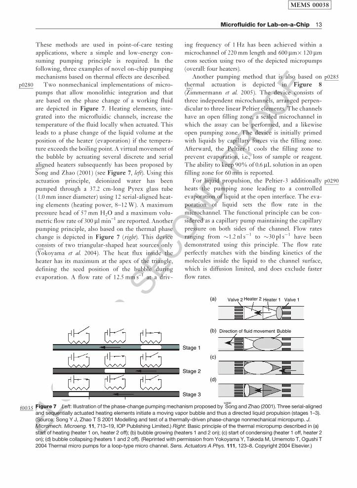
mechanisms based on thermal effects are described.p0280 Two nonmechanical implementations of micro-
pumps that allow monolithic integration and that
are based on the phase change of a working fluid
are depicted in Figure 7. Heating elements, inte-
grated into the microfluidic channels, increase the
temperature of the fluid locally when actuated. This
leads to a phase change of the liquid volume at the
position of the heater (evaporation) if the tempera-
ture exceeds the boiling point. A virtual movement of
the bubble by actuating several discrete and serial
aligned heaters subsequently has been proposed byb0690
Song and Zhao (2001) (see Figure 7, left). Using this
actuation principle, deionized water has been
pumped through a 37.2 cm-long Pyrex glass tube
(1.0 mm inner diameter) using 12 serial-aligned heat-
ing elements (heating power, 8–12 W). A maximum
pressure head of 57 mm H2O and a maximum volu-
metric flow rate of 300 ml min–1 are reported. Another
pumping principle, also based on the thermal phase
change is depicted in Figure 7 (right). This device
consists of two triangular-shaped heat sources only
(b0880
Yokoyama et al. 2004). The heat flux inside the
heater has its maximum at the apex of the triangle,
defining the seed position of the bubble during
evaporation. A flow rate of 12.5 mm s–1 at a driv-
ing frequency of 1 Hz has been achieved within a
microchannel of 220 mm length and 600mm� 120mm
cross section using two of the depicted micropumps
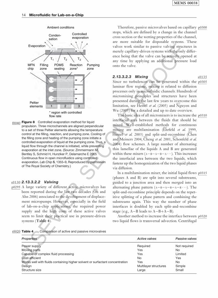
(overall: four heaters).p0285Another pumping method that is also based on
thermal actuation is depicted in Figure 8
(b0915
Zimmermann et al. 2005). The device consists of
three independent microchannels, arranged perpen-
dicular to three linear Peltier elements. The channels
have an open filling zone, a sealed microchannel in
which the assay can be performed, and a likewise
open pumping zone. The device is initially primed
with liquids by capillary forces via the filling zone.
Afterward, the Peltier-1 cools the filling zone to
prevent evaporation, i.e., loss of sample or reagent.
The ability to keep 90% of 0.6 mL solution in an open
filling zone for 60 min is reported.p0290For liquid propulsion, the Peltier-3 additionally
heats the pumping zone leading to a controlled
evaporation of liquid at the open interface. The eva-
poration of liquid sets the flow rate in the
microchannel. The functional principle can be con-
sidered as a capillary pump maintaining the capillary
pressure on both sides of the channel. Flow rates
ranging from �1.2 nl s�1 to �30 pl s�1 have been
demonstrated using this principle. The flow rate
perfectly matches with the binding kinetics of the
molecules inside the liquid to the channel surface,
which is diffusion limited, and does exclude faster
flow rates.
Stage 1
Stage 2
Stage 3
(a)
(b)
(c)
(d)
Valve 2
Direction of fluid movement Bubble
Valve 1Heater 2 Heater 1
Figure 7f0035 Left: Illustration of the phase-change pumping mechanism proposed byb0690
Song and Zhao (2001). Three serial-aligned
and sequentially actuated heating elements initiate a moving vapor bubble and thus a directed liquid propulsion (stages 1–3).
(Source: Song Y J, Zhao T S 2001 Modelling and test of a thermally-driven phase-change nonmechanical micropump. J.Micromech. Microeng. 11, 713–19, IOP Publishing Limited.) Right: Basic principle of the thermal micropump described in (a)
start of heating (heater 1 on, heater 2 off); (b) bubble growing (heaters 1 and 2 on); (c) start of condensing (heater 1 off, heater 2
on); (d) bubble collapsing (heaters 1 and 2 off). (Reprinted with permission from Yokoyama Y, Takeda M, Umemoto T, Ogushi T
2004 Thermal micro pumps for a loop-type micro channel. Sens. Actuators A Phys. 111, 123–8. Copyright 2004 Elsevier.)
MEMS 00038
Microfluidic for Lab-on-a-Chip 13
ELS
EVIE
RSEC
ON
DPR
OO
Fs0130 2.13.3.2.2 Valving
p0295 A large variety of different active microvalves hasbeen reported during the last two decades (
b0565
Oh andAhn 2006) associated to the development of displace-ment micropumps. However, especially in the fieldof lab-on-a-chip applications, the required powersupply and the high costs of these active valvesseem to limit their practical use in pressure-drivensystems (Table 4).
p0300Therefore, passive microvalves based on capillarystops, which are defined by a change in the channelcross section or the wetting properties of the channel,are more suitable for disposable systems. Thesevalves work similar to passive valving structures inmerely capillary-driven systems with the only differ-ence being that the valve can be actively opened atany time by applying an additional pressure loadonto the valve.
s01352.13.3.2.3 Mixing
p0305Since no turbulences can be generated within thelaminar flow regime, mixing is related to diffusionprocesses only in microfluidic channels. Hundreds ofmicromixing principles and structures have beenpresented during the last few years to overcome thislimitation, see
b0340
Hessel et al. (2005) andb0555
Nguyen andWu (2005) for a detailed and up to date overview.
p0310The basic idea of all micromixers is to increase theinterfacial area between the fluids that should bemixed. Well-established methods for continuousmixing are multilamination (
b0165
Ehrfeld et al. 1999,b0335
Hessel et al. 2003) and split-and-recombine (b0090
Chenand Meiners 2004,
b0095
Cheng et al. 2001,b0645
Schonfeld et al.2004) flow schemes. A large number of alternatingthin lamellae of the liquids A and B are generatedwithin these mixers (A�B�A�B�A� � �). This increasesthe interfacial area between the two liquids, whichfastens up the homogenization of the two liquid phasesvia diffusion.
p0315In a multilamination mixer, the initial liquid flows(phases A and B) are split into several substreams,guided to a junction area and then merged into analternating phase pattern (A�B�A�B�A�B � � �). Thesplit-and-recombine principle depends on the repet-itive splitting of a phase pattern and combining thesubstreams again. This way the number of phaseinterfaces is doubled by each split-and-recombinestage (e.g., A�B leads to A�BþA�B).
p0320Another method to increase the interface betweentwo liquid flows is transversal advection. Centrifugal
t0020 Table 4 Comparison of active and passive microvalves
Properties Active valves Passive valves
Power supply Required Not required
Moving parts Yes NoCapable of complex fluid processing Yes Limited
Cost-efficient No Yes
Works well with fluids containing higher solvent or surfactant concentration Yes No
Design Multilayer structures SimpleStructure size Large Small
Ambient conditions
Evaporation
MFNchip
Fillingzone
PDMSsealing
Reactionzone*
Pumpingzone
Peltierelements 1 2 3
T1 T2 T3
* region with controlledflow rate
Conden-sation
Controlledevaporation
Figure 8f0040 Controlled evaporation method for liquid
propulsion. Three microchannels are aligned perpendicularto a set of three Peltier elements allowing the temperature
control at the filling, reaction, and pumping zone. Cooling of
the filling zone and heating of the pumping zone initiate acontrolled evaporation of liquid at the pumping zone. Thus, a
liquid flow through the channel is initiated, while preventing
evaporation at the inlet zone. (Source: Zimmermann M,
Bentley S, Schmid H, Hunziker P, Delamarche E 2005Continuous flow in open microfluidics using controlled
evaporation. Lab Chip 5, 1355–9, Reproduced by permission
of The Royal Society of Chemistry.)
MEMS 00038
14 Microfluidic for Lab-on-a-Chip
ELS
EVIE
RSEC
ON
DPR
OO
F
forces within bended channels, for example, are uti-
lized to generate an additional flow component
perpendicular to the initial direction of flow (b0375
Jiang
et al. 2004,b0745
Sudarsan and Ugaz 2006). Due to this
transversal advection, the contact interface increases
along the channel and thus mixing is supported.
Advection can also be induced in simple straight
channels at low Reynolds numbers (<100) by manu-
facturing a (staggered herring bone-shaped) surface
texture on one channel wall (b0385
Johnson et al. 2002,b0740
Stroock et al. 2002).p0325 All the principles described so far are intended to
mix different liquid flows and therefore called con-
tinuous micromixers. However, the mixing of liquids,
located within a microchamber, can also be of inter-
est. Active micromixers are mainly used for this
purpose, e.g., by moving magnetic particles through
the chamber.
s0140 2.13.3.2.4 Metering
p0330 Metering on pressure-driven platforms is typically
realized by controlling liquid flows into or through
reaction chambers possibly supported by flow rate
sensors. With these methods, however, metering, iso-
lation, and further processing of a discrete liquid
volume are not possible. Therefore additional active
or passive valving structures are required that can
release the liquid out of a metering chamber after it
has been metered to a defined volume via an overflow
channel. Such a structure utilizing a passive, hydro-
phobic valve for stopping the liquid and metering it to
a defined volume has been presented byb0860
Yamada and
Seki (2004). Metered liquid volumes of 3.5 and 20 nl
have been demonstrated in these structures.
s01452.13.3.2.5 Switching
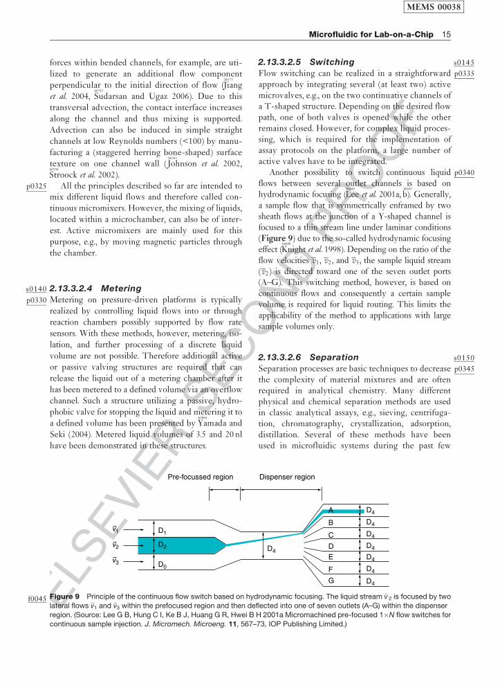
p0335Flow switching can be realized in a straightforwardapproach by integrating several (at least two) activemicrovalves, e.g., on the two continuative channels ofa T-shaped structure. Depending on the desired flowpath, one of both valves is opened while the otherremains closed. However, for complex liquid proces-sing, which is required for the implementation ofassay protocols on the platform, a large number ofactive valves have to be integrated.
p0340Another possibility to switch continuous liquidflows between several outlet channels is based onhydrodynamic focusing (
b0440
Lee et al. 2001a,b0445
b). Generally,a sample flow that is symmetrically enframed by twosheath flows at the junction of a Y-shaped channel isfocused to a thin stream line under laminar conditions(Figure 9) due to the so-called hydrodynamic focusingeffect (
b0400
Knight et al. 1998). Depending on the ratio of theflow velocities v1, v2, and v3, the sample liquid stream(v2) is directed toward one of the seven outlet ports(A–G). This switching method, however, is based oncontinuous flows and consequently a certain samplevolume is required for liquid routing. This limits theapplicability of the method to applications with largesample volumes only.
s01502.13.3.2.6 Separation
p0345Separation processes are basic techniques to decreasethe complexity of material mixtures and are oftenrequired in analytical chemistry. Many differentphysical and chemical separation methods are usedin classic analytical assays, e.g., sieving, centrifuga-tion, chromatography, crystallization, adsorption,distillation. Several of these methods have beenused in microfluidic systems during the past few
D1
D2
Pre-focussed region Dispenser region
v3 D0
D4
D4
D4
D4
D4
D4
D4
D4
A
B
C
D
E
F
G
v1
v2
Figure 9f0045 Principle of the continuous flow switch based on hydrodynamic focusing. The liquid stream v2 is focused by twolateral flows v1 and v3 within the prefocused region and then deflected into one of seven outlets (A–G) within the dispenser
region. (Source: Lee G B, Hung C I, Ke B J, Huang G R, Hwei B H 2001a Micromachined pre-focused 1�N flow switches for
continuous sample injection. J. Micromech. Microeng. 11, 567–73, IOP Publishing Limited.)
MEMS 00038
Microfluidic for Lab-on-a-Chip 15
ELS
EVIE
RSEC
ON
DPR
OO
F
years, and novel separation principles utilizing thefundamental different hydrodynamics in microchan-nels have also been proposed.
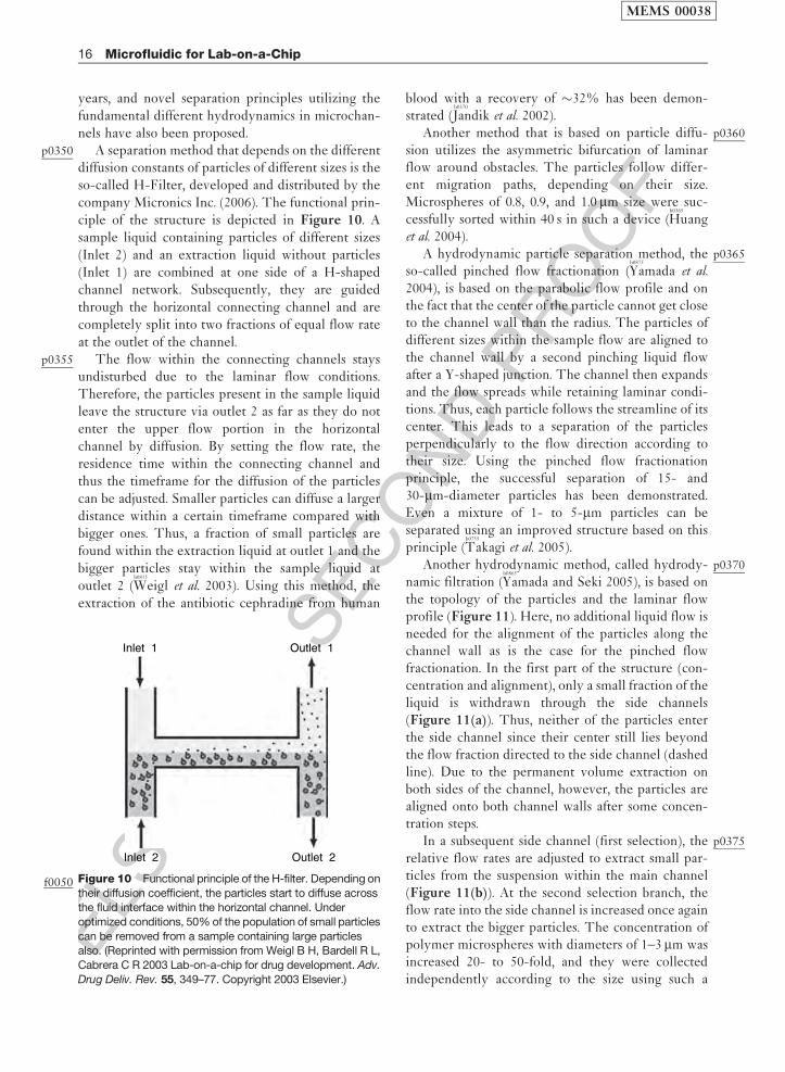
p0350 A separation method that depends on the differentdiffusion constants of particles of different sizes is theso-called H-Filter, developed and distributed by thecompany Micronics Inc. (2006). The functional prin-ciple of the structure is depicted in Figure 10. Asample liquid containing particles of different sizes(Inlet 2) and an extraction liquid without particles(Inlet 1) are combined at one side of a H-shapedchannel network. Subsequently, they are guidedthrough the horizontal connecting channel and arecompletely split into two fractions of equal flow rateat the outlet of the channel.
p0355 The flow within the connecting channels staysundisturbed due to the laminar flow conditions.Therefore, the particles present in the sample liquidleave the structure via outlet 2 as far as they do notenter the upper flow portion in the horizontalchannel by diffusion. By setting the flow rate, theresidence time within the connecting channel andthus the timeframe for the diffusion of the particlescan be adjusted. Smaller particles can diffuse a largerdistance within a certain timeframe compared withbigger ones. Thus, a fraction of small particles arefound within the extraction liquid at outlet 1 and thebigger particles stay within the sample liquid atoutlet 2 (
b0815
Weigl et al. 2003). Using this method, theextraction of the antibiotic cephradine from human
blood with a recovery of �32% has been demon-strated (
b0370
Jandik et al. 2002).p0360Another method that is based on particle diffu-
sion utilizes the asymmetric bifurcation of laminarflow around obstacles. The particles follow differ-ent migration paths, depending on their size.Microspheres of 0.8, 0.9, and 1.0 mm size were suc-cessfully sorted within 40 s in such a device (
b0365
Huanget al. 2004).
p0365A hydrodynamic particle separation method, theso-called pinched flow fractionation (
b0875
Yamada et al.2004), is based on the parabolic flow profile and onthe fact that the center of the particle cannot get closeto the channel wall than the radius. The particles ofdifferent sizes within the sample flow are aligned tothe channel wall by a second pinching liquid flowafter a Y-shaped junction. The channel then expandsand the flow spreads while retaining laminar condi-tions. Thus, each particle follows the streamline of itscenter. This leads to a separation of the particlesperpendicularly to the flow direction according totheir size. Using the pinched flow fractionationprinciple, the successful separation of 15- and30-mm-diameter particles has been demonstrated.Even a mixture of 1- to 5-mm particles can beseparated using an improved structure based on thisprinciple (
b0755
Takagi et al. 2005).p0370Another hydrodynamic method, called hydrody-
namic filtration (b0865
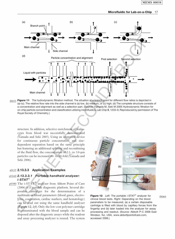
Yamada and Seki 2005), is based onthe topology of the particles and the laminar flowprofile (Figure 11). Here, no additional liquid flow isneeded for the alignment of the particles along thechannel wall as is the case for the pinched flowfractionation. In the first part of the structure (con-centration and alignment), only a small fraction of theliquid is withdrawn through the side channels(Figure 11(a)). Thus, neither of the particles enterthe side channel since their center still lies beyondthe flow fraction directed to the side channel (dashedline). Due to the permanent volume extraction onboth sides of the channel, however, the particles arealigned onto both channel walls after some concen-tration steps.
p0375In a subsequent side channel (first selection), therelative flow rates are adjusted to extract small par-ticles from the suspension within the main channel(Figure 11(b)). At the second selection branch, theflow rate into the side channel is increased once againto extract the bigger particles. The concentration ofpolymer microspheres with diameters of 1–3 mm wasincreased 20- to 50-fold, and they were collectedindependently according to the size using such a
Inlet 1
Inlet 2 Outlet 2
Outlet 1
Figure 10f0050 Functional principle of the H-filter. Depending on
their diffusion coefficient, the particles start to diffuse acrossthe fluid interface within the horizontal channel. Under
optimized conditions, 50% of the population of small particles
can be removed from a sample containing large particlesalso. (Reprinted with permission from Weigl B H, Bardell R L,
Cabrera C R 2003 Lab-on-a-chip for drug development. Adv.
Drug Deliv. Rev. 55, 349–77. Copyright 2003 Elsevier.)
MEMS 00038
16 Microfluidic for Lab-on-a-Chip
ELS
EVIE
RSEC
ON
DPR
OO
Fstructure. In addition, selective enrichment of leuko-cytes from blood was successfully demonstrated(
b0865
Yamada and Seki 2005). Using an improved devicefor continuous particle concentration and size-dependent separation based on the same principlebut featuring an additional splitting and recombiningof the fluid flow, the concentration of 2.1- to 3.0-mmparticles can be increased 60- to 80-fold (
b0870
Yamada andSeki 2006).
s0155 2.13.3.3 Application Examples
s0160 2.13.3.3.1 Portable handheld analyzer:
i-STAT�
p0380 The i-STAT� analyzer from Abbott Point of Care(2006) is a portable diagnostic platform. Several dis-posable cartridges for the determination of amultitude of blood parameters (blood gases, electro-lytes, coagulation, cardiac markers, and hematology)can be read out using the same handheld analyzer(Figure 12, left). Only the low-cost polymer cartridgeis contaminated with the blood sample and can bedisposed after the diagnostic assays while the readoutand assay processing analyzer is reused. The system
(a)
(b)
Figure 12 f0060Left: The portable i-STAT� analyzer for
clinical blood tests. Right: Depending on the bloodparameters to be measured, (a) a certain disposable
cartridge is filled with blood by capillary forces from the
fingertip and (b) later loaded into the analyzer for assay
processing and readout. (Source: Abbott P-C 2006 EastWindsor, NJ, USA, www.abbottpointofcare.com,
accessed 2006.)
Branch point
(a)
(d)
(b) (c)
Side channel
Main channel
Liquid with particles
Main channel
Particle concentration and alignment First selection Second selection
Figure 11f0055 The hydrodynamic filtration method. The situation at a branch point for different flow ratios is depicted in
(a)–(c). The relative flow rate into the side channel is (a) low, (b) medium, or (c) high; (d) The complete structure consists of
a concentration and alignment as well as a selection part. (Source: Yamada M, Seki M 2005 Hydrodynamic filtration for
on-chip particle concentration and classification utilizing microfluidics. Lab Chip 5, 1233–9, Reproduced by permission of TheRoyal Society of Chemistry.)
MEMS 00038
Microfluidic for Lab-on-a-Chip 17
ELS
EVIE
RSEC
ON
DPR
OO
F
reduces the time-to-result for the determination ofimportant blood parameters down to several minutes,enabling faster diagnostic decisions.
p0385 The reagent solution for sensor calibration is con-tained in the cartridge within a foil pouch. Asdepicted in Figure 12, the blood sample is filledinto the cartridge by capillary forces (Figure 12(a))and placed into the analyzer (Figure 12(b)). Duringthe subsequent assay cycle, the analyzer presses thefront of the cartridge, causing a barb to puncture thepouch. This releases the calibrant solution and addi-tionally generates a pressure-driven flow over thesilicon sensor array for measurement. Subsequently,the analyzer presses an air bladder on the cartridge,which pushes the calibrant into the waste reservoirand the blood sample over the sensor array. Thereby,the blood parameters are determined depending onthe type of cartridge and presented at the display ofthe handheld analyzer.
s0165 2.13.3.3.2 Diffusion-based assays:T-Sensor�
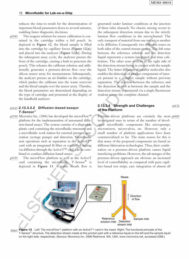
p0390 Micronics Inc. (2006) has developed the microFlow�platform for the implementation of automated diffu-sion-based assays. The system consists of a disposableplastic card containing the microfluidic structures anda microfluidic work station for external pressure gen-eration (syringe pumps) and detection. Microfluidicunit operations such as separation in the ActiveH�card with an integrated H-filter or controlled mixingvia diffusion through the ActiveT� card, can be com-bined to conduct diffusion-based assays.
p0395 The microFlow platform as well as the ActiveTcard containing the microfluidic T-Sensor� isdepicted in Figure 13. A stable sheath flow is
generated under laminar conditions at the junctionof three inlet channels. No chaotic mixing occurs inthe subsequent detection stream due to the strictlylaminar flow conditions in the microchannel. Theonly transport of material from one stream to anotheris by diffusion. Consequently two diffusion zones onboth sides of the central stream evolve. The left zonebetween the reference solution and the detectionliquid represents a system-integrated real-time cali-bration. The other zone evolves at the right side ofthe detection stream being in contact with the sampleliquid. The faster diffusion of smaller molecules alsoenables the detection of smaller components of inter-est present in a complex sample without previousseparation. The reaction between the reference andthe detection as well as between the sample and thedetection stream is measured via a single fluorescentreadout across the complete channel.
s01702.13.3.4 Strength and Challengesof the Platform
p0400Pressure-driven platforms are certainly the mostinvestigated ones in terms of the number of devel-oped microfluidic components like micropumps,micromixers, microvalves, etc. However, only asmall number of platform applications have beencommercialized so far. The main reason for this isthat many of the proposed components are based ondifferent fabrication technologies. Thus, their combi-nation on a pressure-driven platform causes liquidinterfacing problems. However, the advantages of thepressure-driven approach are obvious: an increasedlevel of controllability as compared with pure capil-lary-based test strips, easy integration of almost all
Waste
Directionof flow
Sample inletDetection
stream inlet
Referencesolution inlet
Figure 13f0065 Left: The microFlow� platform with an ActiveT� card in the insert. Right: The functional principle of theT-Sensor� structure. The detection stream meets at the junction part with a reference liquid on the left and the sample liquid
on the right side, respectively. (Source: Micronics Inc. 2006 Redmond, WA, USA, www.micronics.net, accessed 2006.)
MEMS 00038
18 Microfluidic for Lab-on-a-Chip
ELS
EVIE
RSEC
ON
DPR
OO
F
biochemical sensor principles, and the compatibilityto standard lab equipment.
p0405 The real potential of a pressure-driven platformbecomes evident in Section 2.13.4, where the micro-fluidic large-scale integration (LSI) platform – a specialtype of pressure-driven platform – is described, whichis probably the most sophisticated platform conceptpresented in the field so far.
s0175 2.13.4 Microfluidic Large-scaleIntegration
s0180 2.13.4.1 Introduction
p0410 Before the beginning of the 1990s, the screening fornovel active agents in the pharmaceutical industry wasdone by laboratory staff in manually pipetted assays.A biological target molecule is exposed to many com-pounds in order to find a positive, i.e., matchingcompound (hit). The assay result is mainly read outoptically (change in color or fluorescent signal) afterthe reaction. Since the texture of the biological targetmolecule is unknown, all possible combinations out ofa compound library are tested. This merely statisticalapproach is called combinatorial chemistry.
p0415 Over the years, the number of screening experi-ments rapidly grew just as the compound librariesincreased, making manual processing impossible.With the advent of highly automated liquid handlinginstrumentations such as pipetting robots, the num-ber of experiments per day can be increasedenormously. Over 100 000 experiments can be per-formed within a single day using these so-called highthroughput screening (HTS) technologies. A currenttrend is the further reduction of the liquid volumesper screening experiment, e.g., by novel dispensingsystems for liquid volumes in the nanoliter and pico-liter range (see Section 2.13.7). Besides cost issues thefinite amount of (biological) target molecules is themain driving force for this progression.
p0420 However, when shrinking reaction volumes whynot also miniaturize the liquid handling devices to dothousands of chemical experiments on the footprint ofa stamp? In the early 1990s, the realization of such anintegrated microfluidic platform seemed unrealistic interms of simply shrinking microvalves, micropumps,and mixers developed so far. Comparable to theinvention of the transistor in 1947, a pivotal innovationin microfluidics was needed to overcome the existingbarrier. This innovation arose with a novel fabricationtechnology for microfluidic channels, called soft litho-graphy. Using this technology, the monolithic
fabrication of all necessary fluidic components fromone single elastomer material (polydimethylsiloxane,PDMS) became possible, similar to the silicon-basedtechnology in microelectronics.
s01852.13.4.1.1 PDMS – Soft lithography
p0425PDMS is an inexpensive but still powerful materialoffering several advantages compared to silicon orglass. It is a cheap, rubber-like elastomer with goodoptical transparency and biocompatibility. It can bestructured using the soft lithography technique basedon the replication molding on micromachined molds.It has first been used by George Whitesides’s group forthe fabrication of optical devices (
b0850
Xia et al. 1996) andstamps for chemical patterning (
b0840
Xia and Whitesides1998a,
b0845
b). A general and detailed up-to-date view ofthe use of PDMS in different fields of applications canbe found in
b0670
Sia and Whitesides (2003).p0430Thereafter, microfluidic devices have also
been manufactured using PDMS technology(
b0115
Delamarche et al. 1997,b0145
Duffy et al. 1998,b0160
Effenhauseret al. 1997,
b0195
Fu et al. 1999,b0360
Hosokawa et al. 1999). So far,however, PDMS has been used merely as a passivematerial for the realization of microfluidic channels.The strength of the technology, however, reallybecame obvious, when Stephen Quake’s groupexpended the technology toward the multilayer softlithography (MSL) process (
b0600
Quake and Scherer 2000,b0785
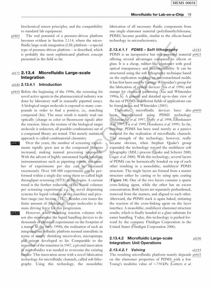
Unger et al. 2000). With this technology, several layersof PDMS can be hermetically bonded on top of eachother resulting in a monolithic, multilayer PDMSstructure. The single layers are formed from a masterstructure either by casting or by using spin coating(Figure 14). One of the two layers contains a sparsecross-linking agent, while the other has an excessconcentration. Both layers are separately prehardened,removed from the masters, and aligned to each other.Afterward, the PDMS stack is again baked, initiatingthe reaction of the cross-linking agent on the layerinterface. A monolithic, multilayer elastomer structureresults, which is finally bonded to a glass substrate foreasier handling. Today, this technology is pushed for-ward by the company Fluidigm Corporation in theUnited States (
b0185
Fluidigm Corporation 2006).
s01902.13.4.2 Microfluidic Large-scaleIntegration: Unit Operations
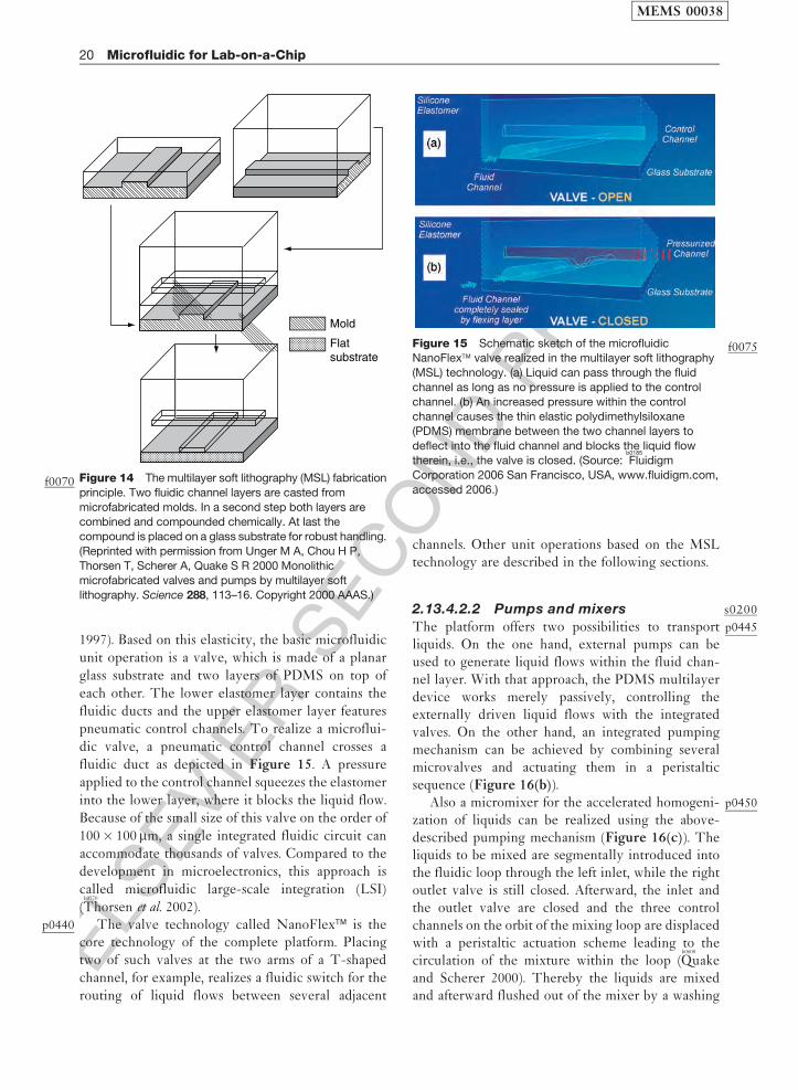
s01952.13.4.2.1 Valving
p0435The resulting microfluidic platform mainly dependson the elastomer properties of PDMS with a lowYoung’s modulus value of �750 kPa (
b0480
Lotters et al.
MEMS 00038
Microfluidic for Lab-on-a-Chip 19
ELS
EVIE
RSEC
ON
DPR
OO
F1997). Based on this elasticity, the basic microfluidicunit operation is a valve, which is made of a planarglass substrate and two layers of PDMS on top ofeach other. The lower elastomer layer contains thefluidic ducts and the upper elastomer layer featurespneumatic control channels. To realize a microflui-dic valve, a pneumatic control channel crosses afluidic duct as depicted in Figure 15. A pressureapplied to the control channel squeezes the elastomerinto the lower layer, where it blocks the liquid flow.Because of the small size of this valve on the order of100� 100 mm, a single integrated fluidic circuit canaccommodate thousands of valves. Compared to thedevelopment in microelectronics, this approach iscalled microfluidic large-scale integration (LSI)(
b0770
Thorsen et al. 2002).p0440 The valve technology called NanoFlex� is the
core technology of the complete platform. Placingtwo of such valves at the two arms of a T-shapedchannel, for example, realizes a fluidic switch for therouting of liquid flows between several adjacent
channels. Other unit operations based on the MSLtechnology are described in the following sections.
s02002.13.4.2.2 Pumps and mixers
p0445The platform offers two possibilities to transportliquids. On the one hand, external pumps can beused to generate liquid flows within the fluid chan-nel layer. With that approach, the PDMS multilayerdevice works merely passively, controlling theexternally driven liquid flows with the integratedvalves. On the other hand, an integrated pumpingmechanism can be achieved by combining severalmicrovalves and actuating them in a peristalticsequence (Figure 16(b)).
p0450Also a micromixer for the accelerated homogeni-zation of liquids can be realized using the above-described pumping mechanism (Figure 16(c)). Theliquids to be mixed are segmentally introduced intothe fluidic loop through the left inlet, while the rightoutlet valve is still closed. Afterward, the inlet andthe outlet valve are closed and the three controlchannels on the orbit of the mixing loop are displacedwith a peristaltic actuation scheme leading to thecirculation of the mixture within the loop (
b0600
Quakeand Scherer 2000). Thereby the liquids are mixedand afterward flushed out of the mixer by a washing
Figure 15 f0075Schematic sketch of the microfluidicNanoFlex� valve realized in the multilayer soft lithography
(MSL) technology. (a) Liquid can pass through the fluid
channel as long as no pressure is applied to the control
channel. (b) An increased pressure within the controlchannel causes the thin elastic polydimethylsiloxane
(PDMS) membrane between the two channel layers to
deflect into the fluid channel and blocks the liquid flowtherein, i.e., the valve is closed. (Source:
b0185
Fluidigm
Corporation 2006 San Francisco, USA, www.fluidigm.com,
accessed 2006.)
Mold
Flatsubstrate
Figure 14f0070 The multilayer soft lithography (MSL) fabrication
principle. Two fluidic channel layers are casted from
microfabricated molds. In a second step both layers arecombined and compounded chemically. At last the
compound is placed on a glass substrate for robust handling.
(Reprinted with permission from Unger M A, Chou H P,
Thorsen T, Scherer A, Quake S R 2000 Monolithicmicrofabricated valves and pumps by multilayer soft
lithography. Science 288, 113–16. Copyright 2000 AAAS.)
MEMS 00038
20 Microfluidic for Lab-on-a-Chip

ELS
EVIE
RSEC
ON
DPR
OO
F
liquid (inlet and outlet valves are opened again).
Using this mixing scheme, an increase in the reaction
kinetics of surface binding assays by nearly two
orders of magnitude has been demonstrated (b0105
Chou
et al. 2001).p0455 Another mixing concept in the microfluidic LSI
platform involves simply opening the valve between
two different chambers containing different liquids.
In this mixing scheme, the liquids mix only by diffu-
sion. Although a merely diffusional mixing is very
slow, it is also very controllable in return. A control-
lable and slow mixing process in particular is
required for protein crystallization, which isdescribed in more detail in Section 2.13.3.3.1.
s02052.13.4.2.3 Multiplexing
p0460The key principle to tap the full potential of the LSIapproach is the multiplexing technology, whichallows the control of N fluid channels with 2 log2 N
control channels as depicted in Figure 17 (b0770
Thorsenet al. 2002). This, for instance, means that 256 fluidchannels can be controlled individually by 33 pneu-matic control channels.
p0465Thorsen et al. demonstrated a microfluidic storagedevice with 1000 independent compartments ofapproximately 250 pl volume and 3574 microvalves.Therefore, two multiplexers, one for the row decod-ing and the other for the column decoding, have beenused. The complete microfluidic chip has a surfacearea of 25 mm� 25 mm.
s02102.13.4.2.4 Metering
p0470Liquid volumes can also be metered using crossedfluid channels and a set of microvalves. Addressed bya multiplexer, the liquid is loaded into a certain fluidchannel in the first step of the metering protocol(Figure 18). Afterward the valves between the dif-ferent chambers are closed and thus the continuous
Control channel Control channels
(a) Valve (b) Pump (c) Mixer
Fluidchannel
Figure 16f0080 Realization of the main unit operations on themultilayer polydimethylsiloxane (PDMS)-based platform.
Based on the NanoFlex� (a) a valve, (b) an integrated
peristaltic micropump, (c) and a micromixer can be
designed.
Bit 3 = 0
Purgebufferinput Sample
output
Washbufferinput
Sample inputHorizontal compartmentalizationvalve
Rowmultiplexor
Column multiplexor Vertical compartmentalizationvalve
5 mm
0 1 2 3 4 5 6 7011
10
0
Bit 2 = 1
Bit 1 = 1
011 = 3
Figure 17f0085 Left: Operational diagram of the microfluidic multiplexer: eight vertical fluid channels can be individually
controlled by six horizontal control channels. The pressurized control channels block the fluid channels only at positionswhere the width of the control channel is widened. Right: Mask design for the microfluidic memory storage device. (Reprinted
with permission from Thorsen T, Maerkl S J, Quake S R 2002 Microfluidic large-scale integration. Science 298, 580–4.
Copyright 2002 AAAS.)
MEMS 00038
Microfluidic for Lab-on-a-Chip 21
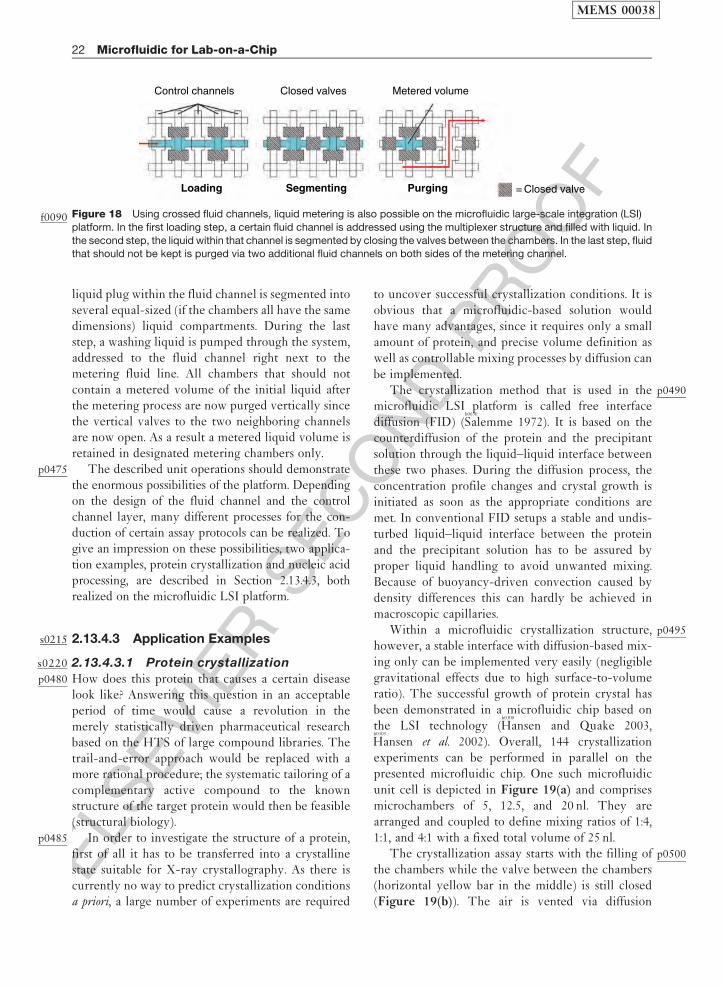
ELS
EVIE
RSEC
ON
DPR
OO
F
liquid plug within the fluid channel is segmented intoseveral equal-sized (if the chambers all have the samedimensions) liquid compartments. During the laststep, a washing liquid is pumped through the system,addressed to the fluid channel right next to themetering fluid line. All chambers that should notcontain a metered volume of the initial liquid afterthe metering process are now purged vertically sincethe vertical valves to the two neighboring channelsare now open. As a result a metered liquid volume isretained in designated metering chambers only.
p0475 The described unit operations should demonstratethe enormous possibilities of the platform. Dependingon the design of the fluid channel and the controlchannel layer, many different processes for the con-duction of certain assay protocols can be realized. Togive an impression on these possibilities, two applica-tion examples, protein crystallization and nucleic acidprocessing, are described in Section 2.13.4.3, bothrealized on the microfluidic LSI platform.
s0215 2.13.4.3 Application Examples
s0220 2.13.4.3.1 Protein crystallization
p0480 How does this protein that causes a certain diseaselook like? Answering this question in an acceptableperiod of time would cause a revolution in themerely statistically driven pharmaceutical researchbased on the HTS of large compound libraries. Thetrail-and-error approach would be replaced with amore rational procedure; the systematic tailoring of acomplementary active compound to the knownstructure of the target protein would then be feasible(structural biology).
p0485 In order to investigate the structure of a protein,first of all it has to be transferred into a crystallinestate suitable for X-ray crystallography. As there iscurrently no way to predict crystallization conditionsa priori, a large number of experiments are required
to uncover successful crystallization conditions. It isobvious that a microfluidic-based solution wouldhave many advantages, since it requires only a smallamount of protein, and precise volume definition aswell as controllable mixing processes by diffusion canbe implemented.
p0490The crystallization method that is used in themicrofluidic LSI platform is called free interfacediffusion (FID) (
b0630
Salemme 1972). It is based on thecounterdiffusion of the protein and the precipitantsolution through the liquid–liquid interface betweenthese two phases. During the diffusion process, theconcentration profile changes and crystal growth isinitiated as soon as the appropriate conditions aremet. In conventional FID setups a stable and undis-turbed liquid–liquid interface between the proteinand the precipitant solution has to be assured byproper liquid handling to avoid unwanted mixing.Because of buoyancy-driven convection caused bydensity differences this can hardly be achieved inmacroscopic capillaries.
p0495Within a microfluidic crystallization structure,however, a stable interface with diffusion-based mix-ing only can be implemented very easily (negligiblegravitational effects due to high surface-to-volumeratio). The successful growth of protein crystal hasbeen demonstrated in a microfluidic chip based onthe LSI technology (
b0300
Hansen and Quake 2003,b0305
Hansen et al. 2002). Overall, 144 crystallizationexperiments can be performed in parallel on thepresented microfluidic chip. One such microfluidicunit cell is depicted in Figure 19(a) and comprisesmicrochambers of 5, 12.5, and 20 nl. They arearranged and coupled to define mixing ratios of 1:4,1:1, and 4:1 with a fixed total volume of 25 nl.
p0500The crystallization assay starts with the filling ofthe chambers while the valve between the chambers(horizontal yellow bar in the middle) is still closed(Figure 19(b)). The air is vented via diffusion
Control channels Closed valves Metered volume
Loading Segmenting Purging = Closed valve
Figure 18f0090 Using crossed fluid channels, liquid metering is also possible on the microfluidic large-scale integration (LSI)
platform. In the first loading step, a certain fluid channel is addressed using the multiplexer structure and filled with liquid. In
the second step, the liquid within that channel is segmented by closing the valves between the chambers. In the last step, fluidthat should not be kept is purged via two additional fluid channels on both sides of the metering channel.
MEMS 00038
22 Microfluidic for Lab-on-a-Chip

ELS
EVIE
RSEC
ON
DPR
OO
F
through the gas-permeable bulk elastomer during thefilling of the dead-end chambers. The filling valves
are closed in the next step and the counterdiffusion isinitiated as soon as the middle valve is opened(Figure 19(c)). The concentration within both cham-bers now changes with time due to the diffusion of
species through the connecting channel. A crystalgrowth initiates in chambers with proper transientconcentrations distributions only.
p0505 The channel between the two chambers has asmall cross-section (10 mm� 100 mm) compared tothat of the two chambers (300 mm� 100 mm). Thus,
it acts like a diffusion impedance, slowing down thediffusion process and implying almost homogeneousconcentrations within the chambers. As a concentra-
tion gradient is apparent only along the length of thechannel, the rate of equilibrium can be influenced bythe geometry of the structure (namely the length of
the channel and the ratio of the chamber volume tothe channel cross-sectional area). The end pointitself, however, is predefined by the volume of thetwo precisely fabricated chambers. The accurate con-
trol over the kinetics of equilibration withoutchanging the chemical evolution has importantimplications for crystal optimization where it is
often desirable to approach crystallization conditionsslowly while conserving the successful thermody-namic variables (
b0300
Hansen and Quake 2003).p0510 The parallel implementation of 48 unit cells in a
single crystallization chip facilitates 144 differentsimultaneous protein crystallization reactions while
consuming only 3.0ml of protein solution – only20 nl per assay (Figure 19(d)). Figure 19 (right)shows a crystal that has been grown within 12 husing the microfluidic LSI chip. In a conventionalsystem, this process lasts over 1 week. The proteincrystallization technology on the LSI platform hasbeen commercialized by the company Fluidigm(Topaz� technology).
s02252.13.4.3.2 Nucleic acid isolation
p0515A second application example of the microfluidic LSIplatform is the purification of nucleic acids from asmall amount of cells. The isolation of DNA ormRNA from microbial or mammalian cells, includingtheir lysis on-chip, has been showed by StephenQuake’s group at Stanford (
b0350
Hong and Quake 2003,b0355
Hong et al. 2004). For the extraction of DNA from acell suspension, the cell membrane has to be destroyedfirst (lysis of the cell). Then, the DNA has to bespecifically separated from the residual cell constitu-ents within the solution. This extraction protocol iscompletely implemented on the microfluidic platformusing the basic unit operation structures for valving,metering, mixing, and switching of fluids.
p0520The channel network for performing the DNAisolation assay is depicted in Figure 20(f). Threeextractions can be performed in parallel with threerotary reactors aligned vertically (the different fluidchannel lines are colored with food dye for visualiza-tion). The chip is operated in two different modes,loading and processing. In the loading mode, the
(a)
(c)
(b)
(d)
1 mm1 mm
1 mm
Figure 19f0095 Left: Microfluidic crystallization structures. (a) Three crystallization assays with different mixing ratios (1:4, 1:1, 4:1)
and a fixed total volume of 25 nl. (b) The central interface valve is closed and the chamber is filled with solution while the air
diffuses through the bulk elastomer. (c) The intermediate valve is opened, initiating the diffusional mixing process. (d) Thecomplete chip features 48 unit cells performing 144 simultaneous crystallization experiments while using 3ml of protein sample
only. Right: Example of protein crystals grown in the described microfluidic structure (scale bar, 100mm). They have been grown
within 12 h only, while the conventional process takes over a week. (Reprinted with permission from Hansen C, Quake S R 2003
Microfluidics in structural biology: Smaller, faster� � � better. Curr. Opin. Struct. Biol. 13, 538–44. Copyright 2003 Eksevier.)
MEMS 00038
Microfluidic for Lab-on-a-Chip 23

ELS
EVIE
RSEC
ON
DPR
OO
Fvalves of the control layer are activated, so that theliquids flow in the north/south direction. During thisstep, the horizontal metering chambers are loadedwith the diluent buffer (green), the bacterial cell solu-tion (red), and the bead suspension (white) as depictedin Figure 20(a). Then, the control valves on thenorth/south channels are closed leading to segmentsof the respective liquids. Also a certain volume of beadsuspension is metered within the microchannel todefine the number of beads that lead to a definedbinding capacity for the later solid-phase extraction(100 pg of DNA on the beads of diameter 2.8mm).
p0525 To exploit the high integration possibilities of theplatform, the three isolation structures differ withregard to the volume of the bacterial cell solution.The volumes used in the top, middle, and bottomstructure are 1.6, 1.0, and 0.4 nl, respectively. Sincethe total volume of each rotary reactor is the same(5 nl), 0.4-, 1.0-, and 1.6-nl dilution buffer are meteredon the platform and added to the cell solution.Subsequently, the chip is switched to the processing
mode: valves are actuated such that flow is allowedonly in an east/west direction and all the three batchreactors are operated in parallel. Lysis buffer (3.0 nl) isinjected from the left to flush the cell solution and thedilution buffer into the rotary reactor (Figure 20(b)).
p0530Within the rotary reactor, the three differentvalves are actuated sequentially to generate a circu-lating flow. This reduces the mixing time fromseveral hours for merely diffusional mixing to severalminutes in the micromixing scheme (Figure 20(c)).As a result, the bacterial cells within the reactor arecompletely lysed after some minutes and can beforwarded to the next process step.
p0535Now, the valve at the outlet of the rotary reactor isopened, and the solution containing the lysed cells isflushed out of the ring over the aggregated beads andleaves the structure via the upper waste outlet(Figure 20(d)). The beads are retained within thechannel by a partially closed valve, where the beadslarger than the valve opening cannot pass through.The DNA molecules within the lysed solution bind
Figure 20f0100 Microfluidic large-scale integration (LSI) DNA purification chip (f) and the course of an isolation protocol. (a) The
bacterial cell culture, the dilution, and the lysis buffer are introduced into the chip via fluid channels (open valve, rectangle;closed valve, x in rectangle). (b) The vertical valves are opened, and the three liquids are externally pumped into the circular
mixing channel. (c) Mixing is initiated by circular peristaltic pumping. (d) The mixture containing the lysed cells is flushed by a
washing buffer over a column of microbeads. The DNA molecules bind to the bead surface and the buffers and the residualcell constituents are directed toward the waste outlet. (e) The elution buffer is flushed over beads, the DNA molecules are
transferred into the liquid phase again and leave the structure through the lower outlet. (Reprinted with permission from
Macmillan Publisher Ltd: Hong J W, Studer V, Hang G, Anderson W F, Quake S R 2004 A nanoliter-scale nucleic acid
processor with parallel architecture. Nat. Biotechnol. 22, 435–9. Copyright 2004.)
MEMS 00038
24 Microfluidic for Lab-on-a-Chip

ELS
EVIE
RSEC
ON
DPR
OO
F
to the bead surface. In a subsequent washing step, allunbound components are washed away from the beadcolumn and likewise drained through the waste outlet.
p0540 Purified DNA is recovered from the chip in thelast process step, by introducing elution buffer fromthe left side of the chip, which passes over the aggre-gated beads. The DNA is transferred back into theliquid phase and leaves the system through the lowerDNA outlet. Two valves at the end of the structureact as a fluidic switch, guiding the liquid flow eithertoward the waste or toward the purified DNA outlet.The DNA gained from the on-chip isolation is nowreadily available for further analysis or manipulation.Figure 20(f) shows the complete microfluidic chipfor four parallel DNA isolation assays; it has 26 accessholes, 1 waste hole, and 54 integrated valves withinthe overall 20 mm� 20mm chip.
p0545 Purified genomic DNA from less than 28 bacterialcells (Escherichia coli culture) could be successfullyisolated on the platform. Additionally, seven chipswere used as negative controls in which pure waterwas introduced instead of bacteria, and no signal wasdetected within the off-chip detection (PCR ampli-fication). Thus, it could be shown that it is possible toreduce the required amount of bacterial cells for theisolation of the needed DNA using the microfluidicLSI platform. This corresponds to an increase in thesensitivity of this process by three to four orders ofmagnitude compared with that of conventionalmethods (
b0355
Hong et al. 2004).p0550 Based on this technology, a complete nucleic acid
processor is currently being developed in StephenQuake’s group at Stanford University. Starting fromsingle cells, the isolation of nucleic acid, with a sub-sequent synthesis of cDNA (
b0510
Marcus et al. 2006a), PCR(
b0475
Liu et al. 2003), or real-time polymerase chain reac-tion (RT-PCR) (
b0515
Marcus et al. 2006b) completes theplatform for complete single-cell gene expressionanalysis.
s0230 2.13.4.4 Strength and Challengesof the Platform
p0555 The microfluidic LSI platform has certainly thepotential to become one of the foremost microfluidicplatforms for highly integrated applications. It is aflexible and configurable technology, which standsout owing to its suitability for LSI. The PDMS fab-rication technology is comparably cheap and robust,and it can be used to fabricate disposables.Reconfigured layouts can be assembled from a smallset of validated elements, and design iteration periods
for new chips are on the order of days. Some of thesystem functions are hardware defined by the fluidiccircuitry but others, such as process sequences, can beprogrammed from outside easily. The approach ofbuilding up an entire processor from a very limitedset of elementary units resembles the microelectro-nics industry in which functional steps are configuredby a circuit of transistors and capacitors.
p0560Limitations of the platform are related to thematerial properties of PDMS: for example, chemicalsthat are not inert to the elastomer cannot be pro-cessed, or elevated temperatures, such as inmicroreaction technology, are not feasible. Also theimplementation of applications in the field of point-of-care diagnostics, where often a handheld device isrequired, does not seem to be beneficial using the LSIplatform. The external pressure sources and valveshave to be shrunk to a smaller footprint, which istechnically feasible of course, but the costs would behigher in comparison to other platform concepts.
s02352.13.5 Centrifugal Microfluidics
p0565The approach of using centrifugal forces to processsamples and reagents dates back to the end of the1960s (
b0020
Anderson 1969,b0070
Burtis et al. 1972). At that time,centrifugal analyzers were used to transfer and mix aseries of samples and reagents in the volume rangefrom 1 up to 110 ml into several cuvettes followed byspectrometric monitoring of reactions and real-timedata processing. In the beginning of the 1990s, thecompany Abaxis Inc. (2006) developed the portableclinical chemistry analyzer (
b0635
Schembri et al. 1992,b0640
1995). The system consists of a plastic disposablerotor for processing the specimen, dried reagentspreloaded to the cartridge, and an analyzer instru-ment for actuation and readout (Figure 21).
p0570The next generation of centrifugal devices emergedfrom the technical capabilities offered by microfabrica-tion and microfluidic technologies (
b0150
Duffy et al. 1999,b0175
Ekstrand et al. 2000,b0485
Madou and Kellogg 1998,b0490
Madouet al. 2001). Length scales of the fluidic structures in therange of a few hundred micrometers allow parallelprocessing of up to a hundred units assembled on thedisk. This enables a high throughput of many tests byhighly parallel and automated liquid handling. In addi-tion, the new opportunities arising from theminiaturization of the centrifugal fluidics cut downthe assay volumes to <1ml. In particular, fields suchas drug screening, where precious samples are ana-lyzed, benefit from the low assay volumes.
MEMS 00038
Microfluidic for Lab-on-a-Chip 25

ELS
EVIE
RSEC
ON
DPR
OO
F
Furthermore, the miniaturized assays can also offershorter time-to-result and thus either higher through-put or shorter therapeutic turnaround times for criticalcare applications. The centritugal microfluidic approachis also referred to as ‘lab-on-a-disk’.
s0240 2.13.5.1 Introduction to the Lab-on-a-DiskApproach
p0575 The basic concept of centrifugal microfludics is thetransport of fluids within a rotating channel by meansof the centrifugal force. For a module rotating withan angular frequency !¼ 2�v, the centrifugal forcedensity
f! ¼ �! !� rð Þ ½3�
acts on a fluid of mass density � at a radial position r.This pumping force is directed in a radial outwarddirection, thus driving liquid plugs toward outerdiameters as long as they possess a net radial pluglength. Besides the liquid properties, only the radialposition and the rotational speed define the pumpingforce and thus the liquid handling actuation. This easesthe parallelization of several identical microfluidicstructures being placed on one rotating substrate atdifferent angular, but the same radial position.Although these structures experience the same centri-fugal force, they still operate independently of eachother, thus making this scheme of parallelization veryrobust.
p0580 The substitution of pressure-generating pumpingdevices by the pulse-free centrifugally initiatedfluid flow enables complex liquid handling processeswithin a completely passive microstructure. Withoutany moving part, the rotating modules called disks orCDs can be fabricated using cost-efficient
microfabrication technologies for plastics like injec-tion molding. The processes are readily availablefrom the audio compact disk industry, where micro-structure polymer discs have been injection moldedfor several decades. Low-cost disposable disks com-bined with a nondisposable rotary drive anddetecting unit build the modular centrifugal micro-fluidic platform.
p0585Besides the centrifugal force, the Coriolis force canalso be used to manipulate liquid flows on the centri-fugal platform as depicted in Figure 22. It acts onevery moving liquid portion within the rotating frameof reference and scales with the flow velocity as well asthe frequency of rotation. The Coriolis pseudo force isalways directed perpendicular to the direction of flowand even prevails over the centrifugal force over acritical frequency of rotation (
b0135
Ducree et al. 2005).
Blood metering
+
Blood injection
Overflow
Diluentcontainer
Diluentmetering
Referencecuvettes
Assaycuvettes
Figure 21f0105 Left: Schematic of the rotor comprising the fluidic channels, reservoirs, and the cuvettes for optical detection. (Source:
Schembri C T, Ostoich V, Lingane P J, Burd T L, Buhl S N 1992 Portable simultaneous multiple analyte whole-blood analyzer for
point-of-care testing. Clin. Chem. 38, 1665–70. Reproduced by permission of American Association for Clinical chemistry.) Right:
Image of the portable analyzer. (Source: Abaxis Inc. 2006 Union City, CA, USA, www.abaxis.com, accessed 2006.)
Center
Patchfc
fω
ω
r
Δr
(a)
(b)
(c)
ω < ωc
ω < ωc
ω > ωc
Figure 22 f0110Principal centrifugal approach and schematic
sketch of the three valving techniques on the centrifugalplatform. (a) Geometric capillary valve, (b) hydrophobic
valve, and (c) hydrophilic siphon valve.
MEMS 00038
26 Microfluidic for Lab-on-a-Chip

ELS
EVIE
RSEC
ON
DPR
OO
F
s0245 2.13.5.2 Microfluidic Unit Operationson the Centrifugal Platform
s0250 2.13.5.2.1 Fluid transport
p0590 On the centrifugal platform, two pressure-generatingmechanisms are employed to accomplish complexliquid processing protocols. The centrifugal force f!(see eqn [3]) enables the liquid transport in radialoutward direction. This actuation principle can bescaled over a wide range by the frequency of rotation.Small flow rates in the order of nanoliter per secondcan be accomplished to extract molecules from acontinuous flow while passing immobilized capturemolecules. For this purpose the residence time forthe streaming molecules have to be larger than thetime for diffusion of the immobilized molecules. Inreturn also high throughput up to 1 ml s�1 has beenreported in a 3 cm-long microchannel of 260 mm� 195 mm cross section for microprocess engineeringapplications (
b0280
Haeberle et al. 2005). So scaling of flowrates over six orders of magnitude has been demon-strated. Many different (bio-) fluids can be processedon the platform, independent of their chemical com-position, ionic strength, conductivity, or pH valueopening a wide field of possible applications.
p0595 The second microfluidic effect that plays animportant role for liquid propulsion is capillarity.As soon as the disk is at rest or rotates with a smallfrequency of rotation, the always coexistent capillarypressure gains impact. If there is at least one liquid–gas transition, a pressure drop appears at the inter-face. Liquid plugs can be transported in anydirection, especially toward the center of the diskalso in a hydrophilic channel using the capillarypumping mechanism. This is due to the fact thatthe capillary pressure is independent of the angularand radial position of the channel. It, for example,allows the complete initial priming of microchannelsif the proceeding meniscus experiences a highercapillarity than the capillary pressure at the otherend of the liquid plug. Most of the microfluidicstructures for the different unit operations describedin this section are based upon the interplay of cen-trifugal and capillary transport mechanisms.
s0255 2.13.5.2.2 Valving
p0600 Stopping of liquid flows, that is, the realization of aliquid valve, can be realized with different microflui-dic structures on the centrifugal platform. A verysimple valve arises at the sudden expansion of amicrofluidic channel, e.g., into a bigger reservoir.The valving mechanism of this capillary valve is
based on the surface tension that develops at this
expansion and prevents further proceeding to theliquid–gas interface (Figure 22(a)). Under rotation,
however, a certain pressure load
p! ¼ �!2r�r ½4�
due to the artificial gravity is applied on the liquid–gas interface. It depends on the liquid density �, thefrequency of rotation !, the mean radius r , and theradial length �r of the liquid plug (
b0150
Duffy et al. 1999).As soon as this pressure exceeds the surface tensionalcounter pressure, the valve breaks. For a given liquidplug position and length, i.e., for a given set of geo-metric parameters, the valve can be influenced by thefrequency of rotation only and a critical burst fre-quency !c can be attributed to every valve structure.
p0605Another possibility to stop the liquid flow within achannel is the local hydrophobic coating of the chan-
nel walls. The hydrophobic patch defines the stop
position for the liquid–gas interface within a hydro-philic channel of constant channel cross section
(Figure 22(b)). Also this valve is opened as soon as
the rotational frequency exceeds the critical burstfrequency !c and the pressure load due to the liquid
plug above the hydrophobic valve overcomes capil-
larity. The net capillary pressure
�p� _ 2�cos �1ð Þ
r1–
cos �2ð Þr2
� �½5�
of a liquid plug with surface tension �, located in achannel of radius r1 at the first and r2 at the secondliquid–gas interface can be used besides the radialplug length and position of the plug to engineer thecritical burst frequency !c.
p0610A third method utilizes the interplay of inertialand capillary forces in a different way. At high fre-
quencies of rotation, the centrifugal force tends to
leverage of the two liquid–gas interfaces within aU-shaped hydrophilic siphon channel of different
cross sections (Figure 22(c)). Only a small difference
in the radial position caused by the unequal channel
cross sections and thus capillary pressures can beobserved, which is negligible for high frequencies of
rotation. Below a critical frequency !c, however, the
meniscus proceeds toward the smaller duct due to
the higher capillary force therein. As soon as themeniscus has passed the bend and proceeds in a radial
outward direction again there comes a moment when
a net radial length �r > 0 exists. From that moment
on, the centrifugal force supports the moving menis-cus and the whole liquid plug escapes the siphon.
MEMS 00038
Microfluidic for Lab-on-a-Chip 27
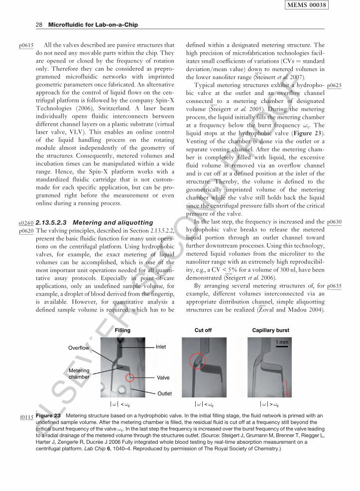
ELS
EVIE
RSEC
ON
DPR
OO
F
p0615 All the valves described are passive structures thatdo not need any movable parts within the chip. Theyare opened or closed by the frequency of rotationonly. Therefore they can be considered as prepro-grammed microfluidic networks with imprintedgeometric parameters once fabricated. An alternativeapproach for the control of liquid flows on the cen-trifugal platform is followed by the company Spin-XTechnologies (2006), Switzerland. A laser beamindividually opens fluidic interconnects betweendifferent channel layers on a plastic substrate (virtuallaser valve, VLV). This enables an online controlof the liquid handling process on the rotatingmodule almost independently of the geometry ofthe structures. Consequently, metered volumes andincubation times can be manipulated within a widerange. Hence, the Spin-X platform works with astandardized fluidic cartridge that is not custom-made for each specific application, but can be pro-grammed right before the measurement or evenonline during a running process.
s0260 2.13.5.2.3 Metering and aliquottingp0620 The valving principles, described in Section 2.13.5.2.2,
present the basic fluidic function for many unit opera-tions on the centrifugal platform. Using hydrophobicvalves, for example, the exact metering of liquidvolumes can be accomplished, which is one of themost important unit operations needed for all quanti-tative assay protocols. Especially in point-of-careapplications, only an undefined sample volume, forexample, a droplet of blood derived from the fingertip,is available. However, for quantitative analysis adefined sample volume is required, which has to be
defined within a designated metering structure. Thehigh precision of microfabrication technologies facil-
itates small coefficients of variations (CVs ¼ standard
deviation/mean value) down to metered volumes inthe lower nanoliter range (
b0730
Steinert et al. 2007).p0625Typical metering structures exhibit a hydropho-
bic valve at the outlet and an overflow channelconnected to a metering chamber of designated
volume (b0715
Steigert et al. 2005). During the metering
process, the liquid initially fills the metering chamberat a frequency below the burst frequency !c. The
liquid stops at the hydrophobic valve (Figure 23).Venting of the chamber is done via the outlet or a
separate venting channel. After the metering cham-ber is completely filled with liquid, the excessive
fluid volume is removed via an overflow channeland is cut off at a defined position at the inlet of the
structure. Thereby, the volume is defined to the
geometrically imprinted volume of the meteringchamber while the valve still holds back the liquid
since the centrifugal pressure falls short of the criticalpressure of the valve.
p0630In the last step, the frequency is increased and thehydrophobic valve breaks to release the meteredliquid portion through an outlet channel toward
further downstream processes. Using this technology,
metered liquid volumes from the microliter to thenanoliter range with an extremely high reproducibil-
ity, e.g., a CV < 5% for a volume of 300 nl, have beendemonstrated (
b0720
Steigert et al. 2006).p0635By arranging several metering structures of, for
example, different volumes interconnected via an
appropriate distribution channel, simple aliquottingstructures can be realized (
b0920
Zoval and Madou 2004).
Filling Cut off Capillary burst
Overflow
Meteringchamber Valve
Inlet1 mm
Outlet
ω < ωcω < ωc ω > ωc
Figure 23f0115 Metering structure based on a hydrophobic valve. In the initial filling stage, the fluid network is primed with an
undefined sample volume. After the metering chamber is filled, the residual fluid is cut off at a frequency still beyond the
critical burst frequency of the valve !c. In the last step the frequency is increased over the burst frequency of the valve leadingto a radial drainage of the metered volume through the structures outlet. (Source: Steigert J, Grumann M, Brenner T, Riegger L,
Harter J, Zengerle R, Ducree J 2006 Fully integrated whole blood testing by real-time absorption measurement on a
centrifugal platform. Lab Chip 6, 1040–4. Reproduced by permission of The Royal Society of Chemistry.)
MEMS 00038
28 Microfluidic for Lab-on-a-Chip

ELS
EVIE
RSEC
ON
DPR
OO
F
These structures split a sample into several definedvolumes enabling the parallel conduction of severalassays from the same sample. Multiparameter diag-nostics and pharmaceutical screening are possibleapplications where such an aliquotting structure isrequired.
s0265 2.13.5.2.4 Mixing
p0640 Mixing of miscible fluids within the laminar regimeon the centrifugal platform can be in the simplestcase accomplished by joining two microfluidic chan-nels to a single meander-shaped channel. Bymaintaining the feeding flows, a stoichiometric cor-rect mixing ratio can be achieved. The requiredlength of the mixing channel depends on the flowrate, i.e., the retention time within the channel, aswell as the diffusional velocity in the transversaldirection. In general, mixing processes can bespeeded up by increasing the interfacial area betweenthe phases to be mixed. However, if two liquidstreams are simply contacted within the laminarregime, the contact interface equals the channelheight and does not increase in the downstreamdirection. An increasing interfacial area along thedirection of flow is possible if the liquid moves notonly along the channel but also perpendicular to it(transversal advection).
p0645 Considering mixing of continuous liquid flowswithin a radial-directed rotating channel, the trans-versal-directed Coriolis force fC automaticallygenerates a transversal liquid flow u(fC) as depictedin Figure 24 (
b0135
Ducree et al. 2005,b0140
2006,b0280
Haeberle et al.2005). The Coriolis force scales with the radial flowvelocity u(f!), which has its maximum in the center ofthe channel due to the parabolic radial velocity
profile (no slip boundary condition at the channelwalls). Therefore, at the center of the channel, theflow experiences the highest Coriolis force fC direc-ted laterally. This leads to a transversal liquidmovement u(fC) from the center to the left and back-ward on the upper and lower channel parts where thesmallest Coriolis counter force is present. This trans-versal advection, also called Coriolis stirring,constantly increases the interfacial area between thetwo concurrent liquid flows and thus acceleratesmixing.
p0650A continuous centrifugal micromixer, utilizing theCoriolis stirring effect, showed an increasing mixingquality toward very high volume throughputs of up to1 ml s–1 per channel. This is enabled by the increasingimpact of the transversal Coriolis force toward higherflow rates (
b0280
Haeberle et al. 2005). It opens an interestingand so far barely explored microprocess engineeringfield for centrifugal microfluidic technologies, whichhowever is not discussed in detail here.
p0655Besides the mixing of continuous liquid flows, thehomogenization of discrete and small liquid volumesinside small chambers is also of importance especiallywhen analyzing small sample volumes (batch-modemixing). One possibility to enhance the mixing of twosmall liquid portions is to guide them into a commonchamber. The streams violently splash against a com-mon chamber wall causing their efficient mixing(
b0920
Zoval and Madou 2004).p0660Another possibility is the active agitation of the
liquid within a mixing chamber either by using peri-odically actuated magnetic microparticles underrotation (
b0235
Grumann et al. 2005) or by means of aninertial effect induced by a fast change of the sense ofrotation (shake-mode mixing). The course of mixingwithin a microchamber under the impact of the shakemode is depicted in Figure 25 (left). The course ofmixing strongly depends on the applied mixing schemeas depicted in Figure 25 (right). The shake-modemixing under an alternate spinning protocol drasticallyenhances the mixing efficiency. Characteristic mixingtimes on the order of several seconds compared toseveral minutes for pure diffusion-based mixing canbe achieved. The shake-mode mixing has been inte-grated into a complete colorimetric assay protocol asdescribed in Section 2.13.5.3.4.
s02702.13.5.2.5 Switching
p0665Switching liquid flow from one common channel toone of at least two continuative channels is veryimportant, e.g., for extraction protocols. A promisingswitching method on the centrifugal platform should
Liquid flow
fω u
u(fω)
u(fc)
fc fc
r
ω
Figure 24f0120 The Coriolis stirring effect within a radial,
rotating microchannel. The inhomogeneous transversal
Coriolis force field fC initiates a transversal advection u(fC)
thus increasing the interface between two liquid streams.(Source: Haeberle S, Brenner T, Schlosser H P, Zengerle R,
Ducree J 2005 Centrifugal micromixer. Chem. Eng. Tech.
28, 613–16. Reproduced by permission of Wiley VCH.)
MEMS 00038
Microfluidic for Lab-on-a-Chip 29
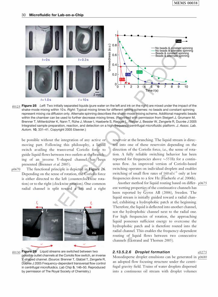
ELS
EVIE
RSEC
ON
DPR
OO
F
be possible without the integration of any active or
moving part. Following this philosophy, a liquid
switch availing the transversal Coriolis force to
guide liquid flows between two outlets at the branch-
ing of an inverse Y-shaped channel has been
presented (b0055
Brenner et al. 2005).p0670 The functional principle is depicted in Figure 26.
Depending on the sense of rotation, the Coriolis force
is either directed to the left (counterclockwise rota-
tion) or to the right (clockwise rotation). One common
radial channel is split toward a left and a right
reservoir at the branching. The liquid stream is direc-ted into one of these reservoirs depending on thedirection of the Coriolis force, i.e., the sense of rota-tion. A fully reliable switching behavior has beenreported for frequencies above �55 Hz for a contin-uous flow. An improved version of Coriolis-basedswitching operates on individual droplets and enablesswitching of small flow rates of 160 nl s–1 only at lowfrequencies down to a few Hz (
b0290
Haeberle et al. 2006b).p0675Another method for liquid routing based on differ-
ent wetting properties of the continuative channels hasbeen reported by
b0275
Gyros AB (2006), Sweden. Theliquid stream is initially guided toward a radial chan-nel, exhibiting a hydrophobic patch at the beginning.Therefore, the liquid is deflected into another channel,not the hydrophobic channel next to the radial one.For high frequencies of rotation, the approachingliquid possesses sufficient energy to overcome thehydrophobic patch and is therefore routed into theradial channel. This enables the frequency-dependentrouting of liquid flows between two consecutivechannels (
b0170
Ekstrand and Thorsen 2005).
s02752.13.5.2.6 Droplet formation
p0680Monodisperse droplet emulsions can be generated inan adopted flow focusing structure under the centri-fugal gravity field. Trains of water droplets dispersedinto a continuous oil stream with droplet volumes
t = 0 s t = 0.3 s
t = 10 st = 1.0 s
1
0.8
0.6
0.4
0.2
00 1 2
Time t (s)2 mm
No beads & constant spinning
Beads & constant spinningNo beads & alternate spinning
Beads & alternate spinning
3 4 5 6
0.5 s
7 min
1.3 s3.0 s
7 8 9 10
Unm
ixed
ness
(a.
u.)
Figure 25f0125 Left: Two initially separated liquids (pure water on the left and ink on the right) are mixed under the impact of the
shake-mode mixing within 10 s. Right: Typical mixing times for different mixing schemes: no beads and constant spinningrepresent mixing via diffusion only. Alternate spinning describes the shake-mode mixing scheme. Additional magnetic beads
within the chamber can be used to further decrease mixing times. (Reprinted with permission from Steigert J, Grumann M,
Brenner T, Mittenbuhler K, Nann T, Ruhe J, Moser I, Haeberle S, Riegger L, Riegler J, Bessler W, Zengerle R, Ducree J 2005Integrated sample preparation, reaction, and detection on a high-frequency centrifugal microfluidic platform. J. Assoc. Lab.
Autom. 10, 331–41. Copyright 2005 Elsevier.)
left right
ink
fω fω
fc
ω ω
fc
Figure 26f0130 Liquid streams are switched between two
possible outlet channels at the Coriolis flow switch, an inverse
Y-shaped channel. (Source: Brenner T, Glatzel T, Zengerle R,
Ducree J 2005 Frequency-dependent transversal flow controlin centrifugal microfluidics. Lab Chip 5, 146–50. Reproduced
by permission of The Royal Society of Chemistry.)
MEMS 00038
30 Microfluidic for Lab-on-a-Chip

ELS
EVIE
RSEC
ON
DPR
OO
F
between 5 and 22 nl with a CV of the droplet diameterbelow 2% are reported (Haeberle et al. 2006c). Theflow focusing structure contacts a central water-guid-ing channel to two symmetric oil flows at a junction.During the droplet formation process, a water plug isexpelled out of the central channel into the junctionarea and is subsequently forced through a geometricalconstriction. This leads to the controlled break-off ofsmall water droplets into the continuous oil flow andthus a monodisperse droplet emulsion. Additionaldroplet-based unit operations like splitting of dropletsor droplet sedimentation have also been realized onthe centrifugal multiphase platform.
s0280 2.13.5.2.7 Separation
p0685 Within the artificial gravity field under rotation, dif-ferent phases can be separated if they possess differentmass densities. This process is called sedimentationand is used as a standard routine in laboratory cent-rifuges. Since lab-on-a-chip systems, especiallywithin the field of point-of-care testing, deal withraw biological samples, which have to be pretreatedbefore the analytical assay can be conducted, a system-immanent separation method is of great importance.
p0690 The extraction of plasma from a blood sample isthe prevalent first step in a complete analytical pro-tocol starting from an untreated whole blood sample.Since blood plasma is less dense than the white andred blood cells it is found in the upper phase, the so-called supernatant after sedimentation. The separa-tion of the cellular and plasma phase in asedimentation chamber, however, is just one part ofa complete plasma extraction process. The secondstep is the spatial extraction of the gained plasmafrom the cellular pellet, located at the bottom of thechamber. This extraction is done by manual or auto-mated pipetting in classic macroscopic plasmaextraction protocols. However, to arrive at an extrac-tion method capable of the seamless integration into
automated centrifugal platform protocols, the plasmaphase has to be extracted automatically within themicrofluidic channel network.
p0695Two methods have been proposed to achieve anintegrated plasma extraction on the centrifugal plat-form. In the first method, plasma and cells areseparated in a sedimentation chamber. A capillaryextraction channel branches from the sedimentationchamber at radial position where only plasma isexpected. It is used to extract the supernatant plasmaphase at lower frequencies via capillary action(
b0640
Schembri et al. 1995). The whole blood sample hasto be metered prior the sedimentation process inorder to guarantee proper function and also to resultin a metered extracted plasma volume. A completeanalyzing system using this extraction method isdescribed in more detail in Section 2.13.4.3.
p0700Another method uses a preseparation of the cellularand plasma phase during the sample flow through anazimuthal-aligned channel of just 300mm radial width(
b0285
Haeberle et al. 2006a). The obtained plasma fraction isthereafter split from the cellular components by adecanting process (Figure 27, left).
p0705The whole extraction proceeds as follows:Initially, a raw blood sample is metered to a fixedvolume defined by an overflow channel next to theoutlet of the metering chamber. Subsequently, themetered sample is forwarded via the drain channelto the decanting structure. Within the drain channelthe blood is preseparated with the plasma phaseflowing on top of the cellular phase. The two jointstreams separate when they enter the decant cham-ber. The more dense cellular phase sinks outwardwhile the less dense plasma phase stays on top.When the decant chamber is entirely filled, pureplasma in the supernatant overflows into a plasmachamber (Figure 27, right). The course of separationconcludes when the entire blood sample has beentransported from the metering chamber into the
Inlet
Vent
Valve Cells
Plasma
Plasma
Interface
Cells
Centrifugal field
300 μm
1 mm
Overflow
Meteringchamber
Decantchamber
Drainchannel
ω
Figure 27f0135 Left: Flow scheme of the decanting structure for plasma extraction from a raw blood sample. Right: Purifiedplasma is decanted into a separate reservoir while the cellular pellet is retained at the bottom of the decant chamber. (Source:
Haeberle S, Brenner T, Zengerle R, Ducree J 2006a Centrifugal extraction of plasma from whole blood on a rotating disk. Lab
Chip 6, 776–81. Reproduced by permission of The Royal Society of Chemistry.)
MEMS 00038
Microfluidic for Lab-on-a-Chip 31
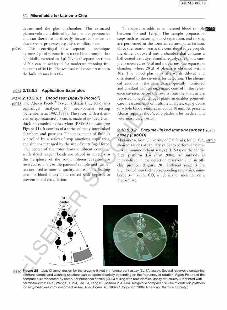
ELS
EVIE
RSEC
ON
DPR
OO
F
decant and the plasma chamber. The extracted
plasma volume is defined by the chamber geometries
and can therefore be directly forwarded to further
downstream processes, e.g., by a capillary duct.p0710 This centrifugal flow separation technique
extracts 2ml of plasma from a raw blood sample that
is initially metered to 5 ml. Typical separation times
of 20 s can be achieved for moderate spinning fre-
quencies of 40 Hz. The residual cell concentration in
the bulk plasma is <1‰.
s0285 2.13.5.3 Application Examples
s0290 2.13.5.3.1 Blood test (Abaxis Picolo�)
p0715 The Abaxis Picolo� system (Abaxis Inc., 2006) is a
centrifugal analyzer for near-patient testing
(b0635
Schembri et al. 1992,b0640
1995). The rotor, with a diam-
eter of approximately 8 cm, is made of molded 2 cm-
thick polymethylmethacrylate (PMMA) plastic (see
Figure 21). It consists of a series of many interlinked
chambers and passages. The movement of fluid is
controlled by a series of stop junctions, capillaries,
and siphons managed by the use of centrifugal force.
The center of the rotor hosts a diluent container
while dried reagent beads are placed in cuvettes in
the periphery of the rotor. Fifteen cuvettes are
reserved to analyze the patients’ sample and further
ten are used as internal quality control. The loading
port for blood injection is coated with heparin to
prevent blood coagulation.
p0720The operator adds an unmetered blood samplebetween 90 and 120 ml. The sample preparationsteps such as metering, blood separation, and mixingare performed in the rotor in an automatic fashion.Once the rotation starts, the centrifugal force propelsthe diluent outward into a chamber that contains aball coated with dye. Simultaneously, the blood sam-ple is metered to 75 ml and moves into the separationchamber, where 20 ml of plasma is obtained within30 s. The blood plasma is afterwards diluted anddistributed to the cuvettes for detection. The chemi-cal reactions in the cuvettes are optically monitoredand checked with an enzymatic control in the refer-ence cuvettes before the results from the analysis arereported. The centrifugal platform enables point-of-care measurements of multiple analytes, e.g., glucoseof whole blood samples in about 10 min. At present,Abaxis supplies the Piccolo platform for medical andveterinary diagnostics.
s02952.13.5.3.2 Enzyme-linked immunosorbent
assay (LabCD)
p0725Madou et al. from University of California, Irvine, CA,showed a series of capillary valves to perform enzyme-linked immunosorbent assays (ELISAs) on the centri-fugal platform (
b0425
Lai et al. 2004). An antibody isimmobilized in the detection reservoir 2 in an off-chip protocol (Figure 28). Different reagents arethen loaded into their corresponding reservoirs, num-bered 3–7 on the CD, which is then mounted on amotor plate.
7
65
4
3
2
1
centerCD
Figure 28f0140 Left: Channel design for the enzyme-linked immunosorbent assay (ELISA) assay. Several reservoirs containingdifferent sample and washing solutions can be opened serially depending on the frequency of rotation. Right: Picture of the
compact disk fabricated by computer numerical control (CNC) milling with four identical assay structures. (Reprinted with
permission from Lai S, Wang S, Luo J, Lee L J, Yang S T, Madou M J 2004 Design of a compact disk-like microfluidic platformfor enzyme-linked immunosorbent assay. Anal. Chem. 76, 1832–7. Copyright 2004 American Chemical Society.)
MEMS 00038
32 Microfluidic for Lab-on-a-Chip
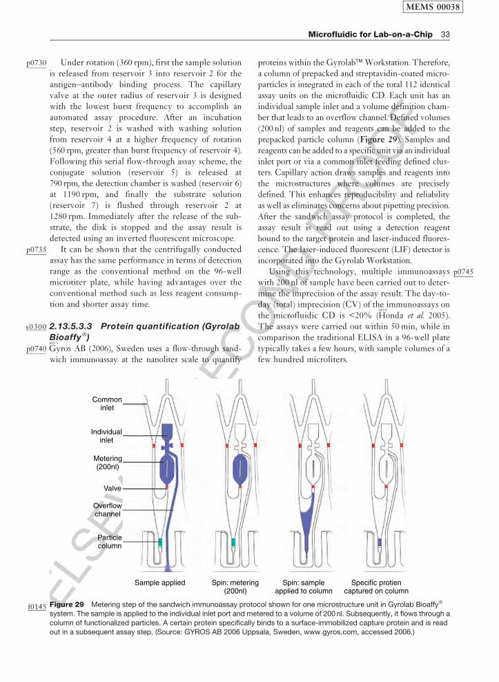
ELS
EVIE
RSEC
ON
DPR
OO
F
p0730 Under rotation (360 rpm), first the sample solutionis released from reservoir 3 into reservoir 2 for theantigen–antibody binding process. The capillaryvalve at the outer radius of reservoir 3 is designedwith the lowest burst frequency to accomplish anautomated assay procedure. After an incubationstep, reservoir 2 is washed with washing solutionfrom reservoir 4 at a higher frequency of rotation(560 rpm, greater than burst frequency of reservoir 4).Following this serial flow-through assay scheme, theconjugate solution (reservoir 5) is released at790 rpm, the detection chamber is washed (reservoir 6)at 1190 rpm, and finally the substrate solution(reservoir 7) is flushed through reservoir 2 at1280 rpm. Immediately after the release of the sub-strate, the disk is stopped and the assay result isdetected using an inverted fluorescent microscope.
p0735 It can be shown that the centrifugally conductedassay has the same performance in terms of detectionrange as the conventional method on the 96-wellmicrotiter plate, while having advantages over theconventional method such as less reagent consump-tion and shorter assay time.
s0300 2.13.5.3.3 Protein quantification (Gyrolab
Bioaffy�)
p0740b0275
Gyros AB (2006), Sweden uses a flow-through sand-wich immunoassay at the nanoliter scale to quantify
proteins within the Gyrolab� Workstation. Therefore,a column of prepacked and streptavidin-coated micro-particles is integrated in each of the total 112 identicalassay units on the microfluidic CD. Each unit has anindividual sample inlet and a volume definition cham-ber that leads to an overflow channel. Defined volumes(200 nl) of samples and reagents can be added to theprepacked particle column (Figure 29). Samples andreagents can be added to a specific unit via an individualinlet port or via a common inlet feeding defined clus-ters. Capillary action draws samples and reagents intothe microstructures where volumes are preciselydefined. This enhances reproducibility and reliabilityas well as eliminates concerns about pipetting precision.After the sandwich assay protocol is completed, theassay result is read out using a detection reagentbound to the target protein and laser-induced fluores-cence. The laser-induced fluorescent (LIF) detector isincorporated into the Gyrolab Workstation.
p0745Using this technology, multiple immunoassayswith 200 nl of sample have been carried out to deter-mine the imprecision of the assay result. The day-to-day (total) imprecision (CV) of the immunoassays onthe microfluidic CD is <20% (
b0345
Honda et al. 2005).The assays were carried out within 50 min, while incomparison the traditional ELISA in a 96-well platetypically takes a few hours, with sample volumes of afew hundred microliters.
Commoninlet
Individualinlet
Metering(200nl)
Valve
Overflowchannel
Particlecolumn
Sample applied Spin: metering(200nl)
Spin: sampleapplied to column
Specific protiencaptured on column
Figure 29f0145 Metering step of the sandwich immunoassay protocol shown for one microstructure unit in Gyrolab Bioaffy�
system. The sample is applied to the individual inlet port and metered to a volume of 200 nl. Subsequently, it flows through a
column of functionalized particles. A certain protein specifically binds to a surface-immobilized capture protein and is readout in a subsequent assay step. (Source: GYROS AB 2006 Uppsala, Sweden, www.gyros.com, accessed 2006.)
MEMS 00038
Microfluidic for Lab-on-a-Chip 33
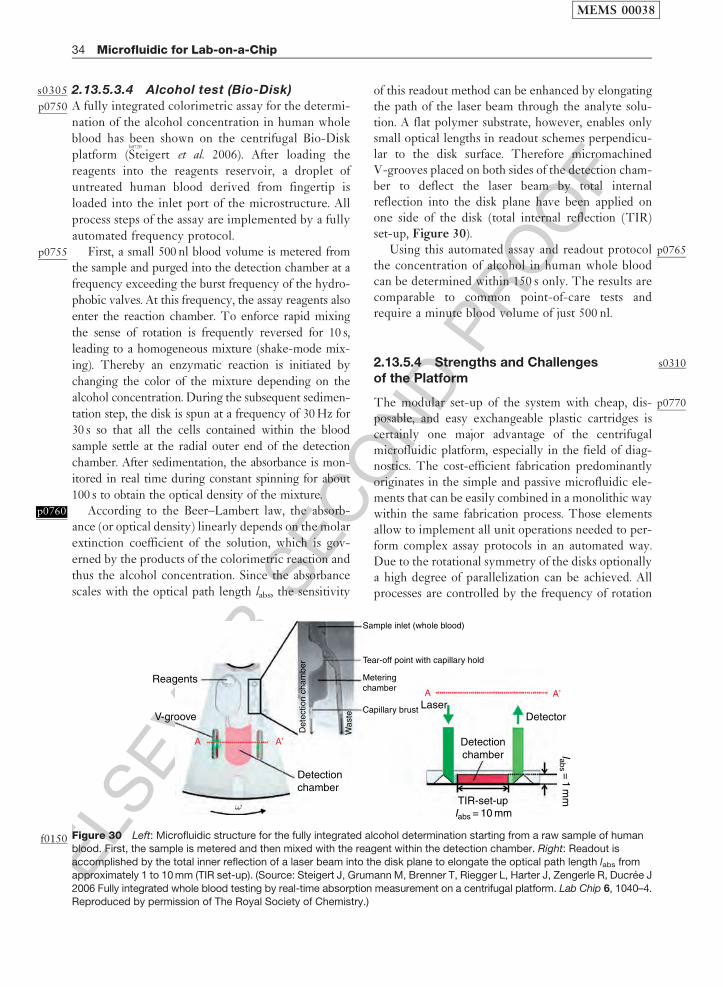
ELS
EVIE
RSEC
ON
DPR
OO
F
s0305 2.13.5.3.4 Alcohol test (Bio-Disk)
p0750 A fully integrated colorimetric assay for the determi-
nation of the alcohol concentration in human whole
blood has been shown on the centrifugal Bio-Disk
platform (b0720
Steigert et al. 2006). After loading the
reagents into the reagents reservoir, a droplet of
untreated human blood derived from fingertip is
loaded into the inlet port of the microstructure. All
process steps of the assay are implemented by a fully
automated frequency protocol.p0755 First, a small 500 nl blood volume is metered from
the sample and purged into the detection chamber at a
frequency exceeding the burst frequency of the hydro-
phobic valves. At this frequency, the assay reagents also
enter the reaction chamber. To enforce rapid mixing
the sense of rotation is frequently reversed for 10 s,
leading to a homogeneous mixture (shake-mode mix-
ing). Thereby an enzymatic reaction is initiated by
changing the color of the mixture depending on the
alcohol concentration. During the subsequent sedimen-
tation step, the disk is spun at a frequency of 30 Hz for
30 s so that all the cells contained within the blood
sample settle at the radial outer end of the detection
chamber. After sedimentation, the absorbance is mon-
itored in real time during constant spinning for about
100 s to obtain the optical density of the mixture.p0760 According to the Beer–Lambert law, the absorb-
ance (or optical density) linearly depends on the molar
extinction coefficient of the solution, which is gov-
erned by the products of the colorimetric reaction and
thus the alcohol concentration. Since the absorbance
scales with the optical path length labs, the sensitivity
of this readout method can be enhanced by elongatingthe path of the laser beam through the analyte solu-tion. A flat polymer substrate, however, enables onlysmall optical lengths in readout schemes perpendicu-lar to the disk surface. Therefore micromachinedV-grooves placed on both sides of the detection cham-ber to deflect the laser beam by total internalreflection into the disk plane have been applied onone side of the disk (total internal reflection (TIR)set-up, Figure 30).
p0765Using this automated assay and readout protocolthe concentration of alcohol in human whole bloodcan be determined within 150 s only. The results arecomparable to common point-of-care tests andrequire a minute blood volume of just 500 nl.
s03102.13.5.4 Strengths and Challengesof the Platform
p0770The modular set-up of the system with cheap, dis-posable, and easy exchangeable plastic cartridges iscertainly one major advantage of the centrifugalmicrofluidic platform, especially in the field of diag-nostics. The cost-efficient fabrication predominantlyoriginates in the simple and passive microfluidic ele-ments that can be easily combined in a monolithic waywithin the same fabrication process. Those elementsallow to implement all unit operations needed to per-form complex assay protocols in an automated way.Due to the rotational symmetry of the disks optionallya high degree of parallelization can be achieved. Allprocesses are controlled by the frequency of rotation
Reagents
LaserDetector
Detectionchamber
TIR-set-upIabs = 10 mm
Iabs =
1 m
m
V-groove
Detectionchamber
ω
Det
ectio
n ch
ambe
r
Was
te
Sample inlet (whole blood)
Tear-off point with capillary hold
Meteringchamber A
A
A’
A’
Capillary brust
Figure 30f0150 Left: Microfluidic structure for the fully integrated alcohol determination starting from a raw sample of humanblood. First, the sample is metered and then mixed with the reagent within the detection chamber. Right: Readout is
accomplished by the total inner reflection of a laser beam into the disk plane to elongate the optical path length labs from
approximately 1 to 10 mm (TIR set-up). (Source: Steigert J, Grumann M, Brenner T, Riegger L, Harter J, Zengerle R, Ducree J
2006 Fully integrated whole blood testing by real-time absorption measurement on a centrifugal platform. Lab Chip 6, 1040–4.Reproduced by permission of The Royal Society of Chemistry.)
MEMS 00038
34 Microfluidic for Lab-on-a-Chip
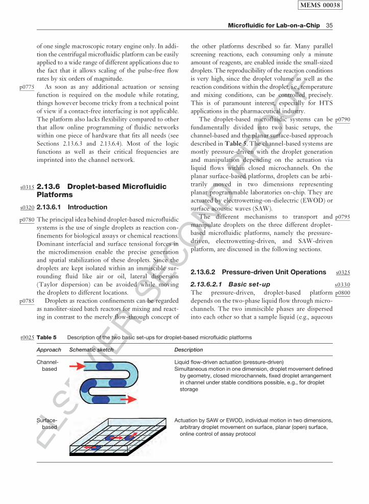
ELS
EVIE
RSEC
ON
DPR
OO
F
of one single macroscopic rotary engine only. In addi-tion the centrifugal microfluidic platform can be easilyapplied to a wide range of different applications due tothe fact that it allows scaling of the pulse-free flowrates by six orders of magnitude.
p0775 As soon as any additional actuation or sensingfunction is required on the module while rotating,things however become tricky from a technical pointof view if a contact-free interfacing is not applicable.The platform also lacks flexibility compared to otherthat allow online programming of fluidic networkswithin one piece of hardware that fits all needs (seeSections 2.13.6.3 and 2.13.6.4). Most of the logicfunctions as well as their critical frequencies areimprinted into the channel network.
s0315 2.13.6 Droplet-based MicrofluidicPlatforms
s0320 2.13.6.1 Introduction
p0780 The principal idea behind droplet-based microfluidicsystems is the use of single droplets as reaction con-finements for biological assays or chemical reactions.Dominant interfacial and surface tensional forces inthe microdimension enable the precise generationand spatial stabilization of these droplets. Since thedroplets are kept isolated within an immiscible sur-rounding fluid like air or oil, lateral dispersion(Taylor dispersion) can be avoided while movingthe droplets to different locations.
p0785 Droplets as reaction confinements can be regardedas nanoliter-sized batch reactors for mixing and react-ing in contrast to the merely flow-through concept of
the other platforms described so far. Many parallelscreening reactions, each consuming only a minuteamount of reagents, are enabled inside the small-sizeddroplets. The reproducibility of the reaction conditionsis very high, since the droplet volume as well as thereaction conditions within the droplet, i.e., temperatureand mixing conditions, can be controlled precisely.This is of paramount interest, especially for HTSapplications in the pharmaceutical industry.
p0790The droplet-based microfluidic systems can befundamentally divided into two basic setups, thechannel-based and the planar surface-based approachdescribed in Table 5. The channel-based systems aremostly pressure-driven with the droplet generationand manipulation depending on the actuation vialiquid flows within closed microchannels. On theplanar surface-based platforms, droplets can be arbi-trarily moved in two dimensions representingplanar programmable laboratories on-chip. They areactuated by electrowetting-on-dielectric (EWOD) orsurface acoustic waves (SAW).
p0795The different mechanisms to transport andmanipulate droplets on the three different droplet-based microfluidic platforms, namely the pressure-driven, electrowetting-driven, and SAW-drivenplatform, are discussed in the following sections.
s03252.13.6.2 Pressure-driven Unit Operations
s03302.13.6.2.1 Basic set-up
p0800The pressure-driven, droplet-based platformdepends on the two-phase liquid flow through micro-channels. The two immiscible phases are dispersedinto each other so that a sample liquid (e.g., aqueous
t0025 Table 5 Description of the two basic set-ups for droplet-based microfluidic platforms
Approach Schematic sketch Description
Channel-
based
Liquid flow-driven actuation (pressure-driven)
Simultaneous motion in one dimension, droplet movement definedby geometry, closed microchannels, fixed droplet arrangement
in channel under stable conditions possible, e.g., for droplet
storage
Surface-
based
Actuation by SAW or EWOD, individual motion in two dimensions,
arbitrary droplet movement on surface, planar (open) surface,
online control of assay protocol
MEMS 00038
Microfluidic for Lab-on-a-Chip 35

ELS
EVIE
RSEC
ON
DPR
OO
F
solution) forms plugs of a certain length, separated by
the carrier liquid (e.g., oil) along the channel. The
flow scheme is called segmented flow, since the size
of the inner phase droplet exceeds the cross-sectional
dimensions of the channel leading to squeezed liquid
plugs. The two-phase flow is pumped throughout the
channels by an externally applied pressure.
s0335 2.13.6.2.2 Droplet generation
and metering
p0805 The most elementary unit operation on the pressure-
driven, droplet-based platform is the initial generation
of the droplets. This step can also be considered as
metering, since the liquid volumes involved in the
latter reaction within the droplet are defined during
the droplet formation process. Generally, two different
microfluidic structures have been reported for a con-
trolled droplet generation, the flow focusing structure
(b0030
Anna et al. 2003,b0380
Joanicot and Ajdari 2005), and the
T-junction (b0560
Nisisako et al. 2002) (Figure 31).p0810 Besides these two most prominent methods, other
microfluidic structures for droplet formation, mainly
for emulsification in the field of microprocess
engineering, have also been proposed. Vertical
microchannels leading into a steady continuous
phase (b0405
Kobayashi et al. 2005) or liquid plugs sliding
down from a microterrace (b0750
Sugiura et al. 2001), for
example, are used to generate droplets with a higher
throughput. Also the production of double emulsions,
e.g., water-in-oil-in-water (W/O/W), has been
shown in a serial arrangement of T-junctions
(b0570
Okushima et al. 2004) or within more complex
interleaved microcapillaries arrangements (b0795
Utadaet al. 2005).
p0815The flow-focusing device and the T-junction,however, are more adequate for the injection of dro-plets into small microchannels inducing a segmentedflow scheme. For both structures, the size of thedroplet is influenced by the strength of the shearforces at the channel junction (higher shear forceslead to smaller droplets). Thus, the droplet diametercan be controlled via the flow rates and flow rateratios of the two phases. In order to ensure a completeisolation of the single droplets, the wetting propertiesof the channel walls have to be assumed to be non-wetting for the sample phase. Thus, the sample phasedroplets are not in contact with the walls and noleakage out of them can cause changing concentra-tions during a reaction.
p0820Also the injection of gaseous bubbles into a con-tinuous liquid stream at a flow focusing structure hasbeen demonstrated (
b0200
Garstecki et al. 2004,b0210
2005b).Using these mechanisms, gas–liquid segmentedflows can be generated within microchannels, whichare, for example, used for the enhanced mixing of twoliquid phases as described in Section 2.13.6.2.6.
s03402.13.6.2.3 Sample load
p0825In order to use the droplets inside a channel as reac-tion confinements, the different liquid educts have tobe loaded into the droplets first. A method to com-bine three different sample liquid streams by a sheathflow arrangement with subsequent injection as acommon droplet into the carrier fluid has beenshown by the group of Rustem F. Ismagilov at theUniversity of Chicago, USA (
b0685
Song et al. 2003b)(Figure 32). Different concentrations and ratios oftwo reagent substreams and a dilution buffer mergeinto one droplet and perform a so-called on-chipdilution (
b0675
Song and Ismagilov 2003). The mixingratios can be adjusted by the volume flow ratio ofthe three streams as depicted in the two exemplaryphotographs in Figure 32. Food dye has been used tocolor the reagents green and red and to visualize theirportion within the generated droplet depending onthe corresponding flow rates.
p0830Using a combination of two opposing T-junctionsconnected to the same channel, the formation ofdroplets of alternating composition has been demon-strated (
b0900
Zheng et al. 2004b). This method can be usedfor protein crystallization (see Section 2.13.6.2.9) orindexing within continuous flow screening experi-ments on the droplet-based platform. There, thefirst droplet of each droplet pair is used to conduct
Flow-focusing structure
T-junction
WaterOil
Oil
Oil
Water
Figure 31f0155 Both microfluidic channel arrangements,
the flow-focusing structure depicted on the top and the
T-junction depicted on the bottom, can be used toreproducibly initiate a droplet break-off. The sketches
describe the arrangement of water as the sample and oil
as the carrier phase.
MEMS 00038
36 Microfluidic for Lab-on-a-Chip
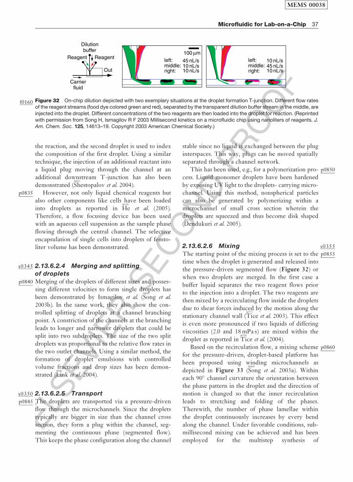
ELS
EVIE
RSEC
ON
DPR
OO
F
the reaction, and the second droplet is used to indexthe composition of the first droplet. Using a similartechnique, the injection of an additional reactant intoa liquid plug moving through the channel at anadditional downstream T-junction has also beendemonstrated (
b0655
Shestopalov et al. 2004).p0835 However, not only liquid chemical reagents but
also other components like cells have been loadedinto droplets as reported in
b0320
He et al. (2005).Therefore, a flow focusing device has been usedwith an aqueous cell suspension as the sample phaseflowing through the central channel. The selectiveencapsulation of single cells into droplets of femto-liter volume has been demonstrated.
s0345 2.13.6.2.4 Merging and splitting
of droplets
p0840 Merging of the droplets of different sizes and posses-sing different velocities to form single droplets hasbeen demonstrated by Ismagilov et al. (
b0685
Song et al.2003b). In the same work, they also show the con-trolled splitting of droplets at a channel branchingpoint. A constriction of the channels at the branchingleads to longer and narrower droplets that could besplit into two subdroplets. The size of the two splitdroplets was proportional to the relative flow rates inthe two outlet channels. Using a similar method, theformation of droplet emulsions with controlledvolume fractions and drop sizes has been demon-strated (
b0465
Link et al. 2004).
s0350 2.13.6.2.5 Transport
p0845 The droplets are transported via a pressure-drivenflow through the microchannels. Since the dropletstypically are bigger in size than the channel crosssection, they form a plug within the channel, seg-menting the continuous phase (segmented flow).This keeps the phase configuration along the channel
stable since no liquid is exchanged between the pluginterspaces. This way, plugs can be moved spatiallyseparated through a channel network.
p0850This has been used, e.g., for a polymerization pro-cess. Liquid monomer droplets have been hardenedby exposing UV light to the droplets- carrying micro-channel. Using this method, nonspherical particlescan also be generated by polymerizing within amicrochannel of small cross section wherein thedroplets are squeezed and thus become disk shaped(
b0125
Dendukuri et al. 2005).
s03552.13.6.2.6 Mixingp0855The starting point of the mixing process is set to the
time when the droplet is generated and released intothe pressure-driven segmented flow (Figure 32) orwhen two droplets are merged. In the first case abuffer liquid separates the two reagent flows priorto the injection into a droplet. The two reagents arethen mixed by a recirculating flow inside the dropletsdue to shear forces induced by the motion along thestationary channel wall (
b0775
Tice et al. 2003). This effectis even more pronounced if two liquids of differingviscosities (2.0 and 18 mPa s) are mixed within thedroplet as reported in
b0780
Tice et al. (2004).p0860Based on the recirculation flow, a mixing scheme
for the pressure-driven, droplet-based platform hasbeen proposed using winding microchannels asdepicted in Figure 33 (
b0680
Song et al. 2003a). Withineach 90� channel curvature the orientation betweenthe phase pattern in the droplet and the direction ofmotion is changed so that the inner recirculationleads to stretching and folding of the phases.Therewith, the number of phase lamellae withinthe droplet continuously increases by every bendalong the channel. Under favorable conditions, sub-millisecond mixing can be achieved and has beenemployed for the multistep synthesis of
Dilutionbuffer
Reagent Reagent
Out
left: 45 nL/s10 nL/s10 nL/s
100 μm
middle:right:
left: 10 nL/s45 nL/s10 nL/s
middle:right:
Carrierfluid
Figure 32f0160 On-chip dilution depicted with two exemplary situations at the droplet formation T-junction. Different flow ratesof the reagent streams (food dye colored green and red), separated by the transparent dilution buffer stream in the middle, are
injected into the droplet. Different concentrations of the two reagents are then loaded into the droplet for reaction. (Reprinted
with permission from Song H, Ismagilov R F 2003 Millisecond kinetics on a microfluidic chip using nanoliters of reagents. J.Am. Chem. Soc. 125, 14613–19. Copyright 2003 American Chemical Society.)
MEMS 00038
Microfluidic for Lab-on-a-Chip 37

ELS
EVIE
RSEC
ON
DPR
OO
F
nanoparticles, for example (b0655
Shestopalov et al. 2004). A
detailed and theoretical description of this mixing
effect is given inb0060
Bringer et al. (2004).p0865 Besides the mixing within liquid droplets, dis-
persed into another liquid carrier phase, mixing
within the carrier phase can also be accelerated by a
segmented flow. The injection of gas bubbles into a
continuous liquid stream forming a segmented gas–
liquid flow has been described by Klavs Jensen and
his group at the MIT (b0240
Gunther et al. 2004,b0245
2005). The
gas bubbles are introduced into the liquid flow and
initiate recirculation flows within the liquid segments
in between due to the motion along the channel wall.
The gas bubbles can be completely separated from
the liquid stream using a planar capillary separator
after the reaction is completed. Using this technol-
ogy, the synthesis of colloidal silica particles has been
demonstrated (b0395
Khan et al. 2004). Compared to a pres-
sure-driven flow without segmentation, the axial
dispersion is eliminated in the proposed gas–liquid
flow scheme. Therefore, the residence time distribu-
tion of the reactants is also narrowed leading to less
polydisperse particles.p0870 Another microfluidic mixing scheme based on a
gas–liquid segmented flow uses an additional
repeated separation and recombining of the channel
(b0205
Garstecki et al. 2005a). Homogenization of two
aqueous streams has been demonstrated after 10
branching units for various flow rates (Reynoldsnumbers between 0.01 and 100) using this mixingscheme.
s03602.13.6.2.7 Incubation
p0875The incubation time of the reagents combined inside adroplet at the injection position can easily be calcu-lated at a certain point of observation from thetraveling distance of the droplet divided by the dropletvelocity. A unique feature of the platform is that atime-resolved monitoring of the incubation can easilybe done by scanning along the channel from the injec-tion point to more downstream positions. Thereby thekinetics of chemical reactions in the order of somemilliseconds can easily be investigated and have beenreported. On the other hand, incubation times on theorder of a week for storing applications have beendemonstrated. This is enabled by the droplet compart-ments that are separated by the carrier fluid, whichprevents evaporation and diffusion. Using thisapproach, several 60 nl liquid droplets containing oneor a few cells were generated within a microfluidicchip and were then flushed into a Teflon� capillarytube for cultivation. The cell densities were still ashigh as in conventional systems after 144 h of growthwithin the droplets (
b0525
Martin et al. 2003).
s03652.13.6.2.8 Switching
p0880Switching on the droplet-based and pressure-drivenplatform means the controlled routing of singledroplets. All liquid routing technologies, availableon the pressure-driven platform described inSection 2.13.3.2.5, can be used to switch droplets inthe channel-type droplet-based microfluidic plat-form. If certain droplets out of a train of dropletsshould be separated, for example, an X-shaped chan-nel crossing can be used. As soon as the droplet ofinterest passes the junction within the main flow, ashort pressure pulse is applied at a side channel todirect the droplet into one of the two remainingoutflow channels.
s03702.13.6.2.9 Application example: protein
crystallization
p0885Protein crystallization (see Section 2.13.4.3.1 fordescription) has been implemented on the pressure-driven, droplet-based platform by Ismagilov andcoworkers (
b0890
Zheng et al. 2003,b0905
2004c). The basic prin-ciple is depicted in Figure 34(a): droplets of threeliquids namely the protein solution, the buffer, andthe precipitant are dispersed into the oil carrierphase. The precipitant concentration inside the
(a)
(b)
REORIENT
stretch and fold
50 μm
Figure 33f0165 Mixing within liquid droplets moving through
bending microfluidic channels shown (a) experimentally
and (b) schematically. (Source: Song H, Bringer M R,
Tice J D, Gerdts C J, Ismagilov R F 2003a Experimentaltest of scaling of mixing by chaotic advection in droplets
moving through microfluidic channels. Appl. Phys. Lett.
83, 4664–6. Reproduced by permission of American
Institute of Physics.)
MEMS 00038
38 Microfluidic for Lab-on-a-Chip

ELS
EVIE
RSEC
ON
DPR
OO
F
droplet is adjusted via the buffer and precipitant flow
rate. Therewith, different concentrations are gener-
ated and transferred into a glass capillary for later
detection. Nonspecific protein adsorption onto the
liquid–liquid interface can be suppressed by adding
certain surfactants to the carrier phase (b0620
Roach et al.
2005). As depicted in Figure 34(b), the droplets
containing the protein crystals can be directly for-
warded into a glass capillary ready for the X-ray
analysis (b0855
Yadav et al. 2005).p0890 As described earlier in this chapter, successful
protein crystallization is initiated for a certain
precipitation concentration only. Therefore, the con-
duction of many crystallization experiments within a
short time and with a reduced amount of protein
sample is favorable and is enabled by the described
sample loading technique. Examples of crystallized
thaumatin proteins are depicted in Figure 34(c).
The effect of mixing on the nucleation of protein
crystallization has been investigated by combining
the described crystallization structure with a winding
mixing channel as described in Section 2.13.6.2.6
(b0080
Chen et al. 2005). Fast chaotic mixing has been
found to be favorable for the formation of well-formed
proteins within the droplets (b0910
Zheng et al. 2005).p0895 Besides the described method for crystallization,
an alternative process in which the concentration
within one droplet is changed over time has also
been developed by the group of Ismagilov, based on
water diffusion between droplets (b0895
Zheng et al. 2004a,b0905
c).
In this case, a carrier liquid that enables diffusion
between the droplets, that is, a water-permeable
liquid, is selected. Alternating droplets of protein
and precipitant on the one hand and a high-
concentration salt solution on the other hand aregenerated using two opposing droplet generationstructures (
b0900
Zheng et al. 2004b). Water diffusesthrough the oil carrier phase from the low salt con-centration, i.e., from the protein-containing dropletto the high-concentration droplet. This steadilyincreases the concentration within the protein-con-taining droplet until the suitable crystallizationcondition is achieved.
p0900Recent developments on the pressure-driven,droplet-based platform aim at HTS applications.Therefore a large number of droplets, each contain-ing a different reagent, are separated and surroundedby a fluorinated carrier fluid within a microcapillary.In order to prevent coalescence during possibly longstorage times, a gas bubble is injected between thedroplets as an additional separation phase (
b0885
Zheng andIsmagilov 2005). Based on this three-phase liquid–liquid–gas system, reliable and HTS assays can beperformed, which could be an alternative for wellplates in the future (
b0085
Chen and Ismagilov 2006).
s03752.13.6.3 Electrowetting-driven UnitOperations
s03802.13.6.3.1 Basic set-up
p0905The electrowetting effect was first described byGabriel Lippmann in 1875 while the recent develop-ments were initiated in the early 1990s byintroducing the idea of using thin insulating layersto separate the conductive liquids from the metallicelectrodes in order to eliminate the problem of elec-trolysis (taken from
b0540
Mugele and Baret (2005) onelectrowetting). This paved the way for the
Buffer(a) (b)
(c)
1 cm
100 μm
Protein Precipitant
PDMS
Fluorinatedoil
Glasscapillary
Figure 34f0170 (a) Schematic illustration of the protein crystallization device and (b) the complete set-up consisting of apolydimethylsiloxane (PDMS) chip and a glass capillary. (c) Examples of thaumatin crystals that were grown inside droplets in
a capillary. (Source: Zheng B, Tice J D, Roach L S, Ismagilov R F 2004c A droplet-based, composite PDMS/glass capillary
microfluidic system for evaluating protein crystallization conditions by microbatch and vapor-diffusion methods with on-chipX-ray diffraction. Angew. Chem. Int. Ed. 43, 2508–11. Reproduced by permission of Wiley VCH.)
MEMS 00038
Microfluidic for Lab-on-a-Chip 39
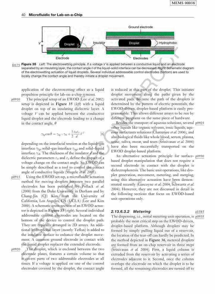
ELS
EVIE
RSEC
ON
DPR
OO
F
application of the electrowetting effect as a liquid
propulsion principle for lab-on-a-chip systems.p0910 The principal setup of an EWOD (
b0455
Lee et al. 2002)setup is depicted in Figure 35 (left) with a liquid
droplet on top of an insulating dielectric layer. A
voltage V can be applied between the conductive
liquid droplet and the electrode leading to a change
in the contact angle, �
�lgcos � ¼ �sg – �sl þ1
2
"0"r
dV 2 ½6�
depending on the interfacial tension at the liquid–gasinterface �lg, solid–gas interface �sg, and solid–liquidinterface �sl. The thickness of the insulator d and thedielectric parameters "0 and "r define the impact of avoltage change on the contact angle. So EWOD canbe simply described as a tool to control the contactangle of conductive liquids (
b0545
Mugele et al. 2005).p0915 Using the EWOD set-up, a microfluidic actuation
method for moving droplets between two parallel
electrodes has been published byb0590
Pollack et al.
(2000) from the Duke University in Durham and by
Chang-Jin (CJ) Kim from the University of
California, Los Angeles, CA (UCLA) (b0450
Lee and Kim
2000). A schematic cross-section of an EWOD actua-
tor is depicted in Figure 35 (right). Several individual
addressable control electrodes are located on the
bottom of the device to control the droplet path.
They are typically arranged in 2D arrays. An addi-
tional hydrophobic layer (mostly Teflon) is added to
the insulator surface to enhance the droplet move-
ment. A common ground electrode in contact with
the liquid droplet replaces the extended electrode.p0920 The droplet, which is enclosed between the two
electrode plates, features a certain volume so that
it covers parts of two addressable electrodes at all
times. If a voltage is applied on one of the control
electrodes covered by the droplet, the contact angle
is reduced at this part of the droplet. This initiatesdroplet movement along the paths given by theactivated pads. Because the path of the droplets isdetermined by the pattern of electric potentials, theEWOD-driven, droplet-based platform is easily pro-grammable. This allows different assays to be run bydifferent programs on the same piece of hardware.
p0925Besides the transport of aqueous solutions, severalother liquids like organic solvents, ionic liquids, aqu-eous surfactants solutions (
b0075
Chatterjee et al. 2006), andalso biological fluids like whole blood, serum, plasma,urine, saliva, sweat, and tears (
b0705
Srinivasan et al. 2004)have also been successfully transported on theEWOD droplet-based platform.
p0930An alternative actuation principle for surface-based droplet manipulation that does not require asecond electrode in contact with the droplet isdielectrophoresis. The basic unit operations, like dro-plet generation, movement, metering, and merging,using this alternative actuation have been demon-strated recently (
b0215
Gascoyne et al. 2004,b0650
Schwartz et al.2004). However, they are not discussed in detail inthe following sections that focus on EWOD-basedunit operations only.
s03852.13.6.3.2 Metering
p0935The dispensing, i.e., initial metering unit operation, isprobably the most critical step on the EWOD-driven,droplet-based platform. Although droplets may beformed by simply pulling liquid out of a reservoir,the location of the tear-off can hardly be predicted. Inthe method depicted in Figure 36, metered dropletsare formed from an on-chip reservoir in three steps(
b0705
Srinivasan et al. 2004). First, a liquid column isextruded from the reservoir by activating a series ofelectrodes adjacent to it. Second, once the columnoverlaps the electrode on which the droplet is to beformed, all the remaining electrodes are turned off to
Ground electrode
ElectrodesElectrode
θV Droplet Droplet HydrophobicInsulator
Figure 35f0175 Left: The electrowetting principle. If a voltage V is applied between a conductive liquid and an electrode
separated by an insulating layer, the contact angle � of the liquid–solid interface can be decreased. Right: Schematic diagram
of the electrowetting actuation of liquid droplets. Several individual addressable control electrodes (bottom) are used tolocally change the contact angle and thereby initiate a droplet movement.
MEMS 00038
40 Microfluidic for Lab-on-a-Chip

ELS
EVIE
RSEC
ON
DPR
OO
F
form a neck in the column. The reservoir electrode isthen activated in the third and last step to pull backthe liquid and break the neck completely to forma droplet. Using this droplet metering structure,droplets of 20 nl volume can be generated with astandard variation below 2% (
b0705
Srinivasan et al. 2004).p0940 Since the droplet dispensing is a crucial step for
the performance and the accuracy of all assays on theEWOD platform, additional measures for a con-trolled liquid metering such as on-chip capacitancemetering for volume control (
b0610
Ren et al. 2004) orthe use of numerical methods for the design ofEWOD structures (
b0040
Berthier et al. 2006) have beenproposed.
s0390 2.13.6.3.3 Mixing
p0945 The most basic of miscible liquids within droplets onthe EWOD platform is by oscillating the dropletbetween two electrodes. Before this active mixingscheme is used, the two droplets containing theliquids to be mixed have to be merged into a singledroplet. This coalesced droplet is then moved alongthe electrodes in an oscillating fashion to induceadvectional effects inside the droplet. An increasingfrequency of droplet movement leads to reducedmixing times. The mixing process can be furtheraccelerated by oscillating over a longer linear elec-trode array. The shortest mixing time for two 1.3-mldroplets in linear oscillation on four electrodes wasabout 4.6 s (
b0585
Paik et al. 2003b). In another work, themixing time was further reduced to less than 3 s using2D arrays (
b0580
Paik et al. 2003a).
s03952.13.6.3.4 Merging and splitting
of droplets
p0950Together with droplet generation from a reservoirand the droplet transport along electrode arrays, thecontrolled merging and splitting of droplets completethe four fundamental fluidic operations consideredessential to build digital microfluidic circuits forlab-on-a-chip applications (
b0100
Cho et al. 2003).p0955The realization of droplet splitting and merging
on three linearly aligned EWOD electrodes isdepicted in Figure 37 (
b0595
Pollack et al. 2002). The initialdroplet volume is first elongated toward the middleelectrode by applying a voltage on it (Figure 37(b)).After a certain time delay, required for the stabiliza-tion of the droplet, the voltage is switched from themiddle to the right electrode, initiating a division ofthe droplet into two subdroplets placed on the leftand the right electrode, as depicted in Figure 37(c)and 37(d). For a subsequent merging of the droplets,the voltage is again switched from the right to themiddle electrode, moving the right subdroplet backagain to the middle position and bringing it in contactwith the left subdroplet (Figure 37(e)–(f)).
s04002.13.6.3.5 Readout
p0960Different readout schemes for biochemical assays havebeen applied to the EWOD-driven, droplet-basedplatform. Colorimetric, enzymatic assays that areimportant for diagnostic applications have been suc-cessfully implemented and glucose concentrationmeasurements on several biological fluids (serum,plasma, urine, and saliva) with good comparableresults have been demonstrated (
b0705
Srinivasan et al. 2004).
Figure 36f0180 Droplet formation from an on-chip reservoir using electrowetting forces only. First, a liquid column is extrudedfrom the reservoir and tears off after the connecting electrode is turned off. (Source: Srinivasan V, Pamula V K, Fair R B 2004
An integrated digital microfluidic lab-on-a-chip for clinical diagnostics on human physiological fluids. Lab Chip 4, 310–15.
Reproduced by permission of The Royal society of Chemistry.)
MEMS 00038
Microfluidic for Lab-on-a-Chip 41

ELS
EVIE
RSEC
ON
DPR
OO
F
p0965 Another example with regard to the use of anEOWD system for the automated sample preparationof peptides and proteins for matrix-assistedlaser desorption/ionization mass spectrometry(MALDI-MS) is reported (
b0820
Wheeler et al. 2004). Inthis work, standard MALDI-MS reagents, analytes,concentrations, and recipes have been demonstratedto be compatible with this technique, and mass spec-tra comparable to those collected by conventionalmethods were obtained.
s0405 2.13.6.4 SAW-driven Unit Operations
s0410 2.13.6.4.1 Basic set-up
p0970 An alternative to the electrowetting-based actuationof droplets on a plane surface has been proposed byAchim Wixforth and his group at the University ofAugsburg, Germany (
b0825
Wixforth 2003). The approachis based on SAW, which are mechanical waves withamplitudes of typically only a few nanometers. In
contrast to ordinary sound waves, which are of long-
itudinal type, SAW are transversal waves. Their
amplitude can be either parallel to the surface
(Love waves) or perpendicular to the surface
(Rayleigh waves) or of mixed type. For the manip-
ulation of droplets on the SAW-based platform,
typically Rayleigh waves are used.p0975The SAW are generated by a piezoelectric trans-
ducer chip (e.g., quartz), which can be fabricated by
placing interdigital electrodes (interdigital trans-
ducer, IDT) on top of a piezoelectric layer, for
example. Liquid droplets are placed on the hydro-
phobic surface of the chip and can be moved by the
SAW on the surface. Appropriate AC signals are
applied to the electrodes only at a certain region of
the piezoelectric layer. Thus the SAW are exclu-
sively generated at the desired location and can be
focused on the droplet. If the acoustic pressure
exerted on the liquid droplet is high enough, the
droplet can be deformed or even be moved as
depicted in Figure 38 (b0830
Wixforth et al. 2004).
(a) (d)
(e)(b)
(c) (f)
Figure 37f0185 A sequence of photographs showing the droplet splitting and merging. (a) Initially, only the left electrode is activated.(b) The middle electrode is then activated and, (c) and (d) after a delay, the voltage is switched from the middle to the right
electrode resulting in division of the droplet. (e) and (f) The original droplet is reassembled by switching the voltage on the right
electrode back to the middle electrode. (Source: Pollack M G, Shenderov A D, Fair R B 2002 Electrowetting-based actuation of
droplets for integrated microfluidics. Lab Chip 2, 96–101. Reproduced by permission of The Royal Society of Chemistry.)
Figure 38f0190 Side view of an approximately 50-nl droplet on the hydrophobic surface (contact angle of about 90�) of apiezoelectric substrate. Left: Resting droplet. Right: The droplet is hit by SAW impinging from the left resulting in a momentary
asymmetry of the wetting angles of the droplet. (Source: Wixforth A, Strobl C, Gauer C, Toegl A, Scriba J, von Guttenberg Z
2004 Acoustic manipulation of small droplets. Anal. Bioanal. Chem. 379, 982–91. With kind permission of Springer Scienceand Business Media.)
MEMS 00038
42 Microfluidic for Lab-on-a-Chip

ELS
EVIE
RSEC
ON
DPR
OO
F
p0980 This approach is also sometimes referred to as flatfluidics, because no cover or slit is required as in theEOWD approach but only a flat surface where theSAW are generated is needed. Today, this technol-ogy is being pushed forward by the companyAdvalytix AG (2006), Germany.
s0415 2.13.6.4.2 Metering
p0985 Metering is accomplished by a combination of locallychanged wetting properties of the surface and the
actuation via SAW. One possible metering process isdepicted in Figure 39. An initial water plug of approxi-mately 100 nl is placed on an oval hydrophilic zone onthe chip surface (Figure 39(a)). After the first actuator(IDT) is activated, SAW propagate horizontally towardthe liquid plug, pushing it to the right across anothersmall hydrophilic metering spot (Figure 39(b)). Afterthe actuation, the liquid volume withdraws to thehydrophilic regions on the chip, leaving behind asmall metered liquid portion (Figure 39(c)). This dro-plet is subsequently moved upward by another IDT for
HydrophobicIDT
IDT
IDT
IDT
Water
(a)
(c) (d)
(b)
Hydrophilic
SAW
SAW
Figure 39f0195 Acoustically driven metering process on the SAW platform. (a)–(d) Hydrophobic and hydrophilic areas areindicated in the schematic sketch on the top. First, the horizontally acting interdigital transducer (IDT) pushes the water
droplet to the right across the hydrophobic substrate. After the actuation, the droplet withdraws meanwhile separating a small
liquid volume, which remains at the small hydrophilic spot, as depicted in (c). In the last step, this metered liquid portion ispushed upward toward another hydrophilic zone. Corresponding photographs of the actual experiment are also depicted.
(Source: Wixforth A, Strobl C, Gauer C, Toegl A, Scriba J, von Guttenberg Z 2004 Acoustic manipulation of small droplets.
Anal. Bioanal. Chem. 379, 982–91. With kind permission of Springer Science and Business Media.)
MEMS 00038
Microfluidic for Lab-on-a-Chip 43

ELS
EVIE
RSEC
ON
DPR
OO
F
further processing (Figure 39(d)). At the bottom ofFigure 39, a sequence of experimental photographsshows the metering process on the open chip surface.
s0420 2.13.6.4.3 Mixing
p0990 Mixing presents a system-immanent unit operationon the SAW-driven, droplet-based platform. A drop-let, which is placed on the substrate and is hit bySAW, experiences an internal streaming due to thevibrating forces of the wave. If the amplitude is notlarge enough for a droplet movement, the liquidinside the droplet is efficiently stirred while its posi-tion on the substrate is retained. The internalstreaming is depicted in Figure 40 where a fluores-cent dye is dissolved into a 50-nl droplet under SAWagitation.
s0425 2.13.6.4.4 Merging and splitting
of droplets
p0995 Using the SAW-based mechanism for droplet move-ment in combination with a certain pattern ofdifferent wetting areas on the chip surface, dropletsplitting as described in Section 2.13.6.4.2 as well asdroplet merging can be accomplished.
p1000 The splitting of one droplet into several smallervolumes of the same size, i.e., aliquotting, is realizedby moving the initial droplet over a hydrophobic/hydrophilic chessboard zone. Since the transport of adroplet depends nonlinearly on the droplet size, theinitial droplet of bigger volume is constantly movedforward, while small, picoliter-sized droplets remainon the hydrophilic parts of the wetting pattern(
b0825
Wixforth 2003).
s0430 2.13.6.4.5 Incubation and entrapment
p1005 For some assay protocols, longer incubation steps atelevated temperatures are also required, e.g., for aPCR amplification. The liquid plug is placed abovea microheating element on the substrate surface forthese incubation steps. However, since the nanoliter-
sized droplet possesses a high surface-to-volumeratio, the liquid volume decreases rapidly due toevaporation. Hence to avoid evaporation, the aque-ous liquid plug is covered with an oil plug having asmaller contact angle. This droplet in droplet config-uration still can be moved via SAW on the substratesurface. Using this technology, a PCR assay within a200-nl droplet enclosed in mineral oil was performedwith an online monitoring of the DNA concentra-tions and provided a sensitivity of 0.1 ng (
b0270
Guttenberget al. 2005).
s04352.13.6.4.6 Readout
p1010The fabrication of the electrodes for the actuators(IDT) as well as the fabrication of the wetting pat-terns on the substrate is done by high-precisionlithographic processes. Therefore, heaters, electro-des, or different types of sensors based on surfacemicromachining can easily be integrated in astraightforward way. Also, optical readout schemeshave been realized for the online fluorescentmonitoring of the RT-PCR progress, for example(
b0270
Guttenberg et al. 2005).
s04402.13.6.5 Strengths and Challengesof the Platform
p1015General advantages of droplet-based microfluidicsare the small liquid volumes of the droplets reducingreagent and sample consumption and thus paving theway for HTS applications. Additionally, the batch-mode operation scheme used in the nanoliter- tomicroliter-sized droplets represents a consistentfurther development of the classic assay protocolsin, for example, well plates.
p1020The pressure-driven approach combines theseadvantages with the high-throughput capabilitiesin a quasi-continuous operational scheme. Thecompletely enclosed liquid droplets furthermoreallow the incubation and storage of liquid assay
Figure 40f0200 Internal streaming is induced within an approximately 50-nl droplet, hit by SAW. The internal mixing process is
visualized by a fluorescent dye placed on the surface of the chip, which is dissolved by the SAW agitation. (Source: Wixforth A,
Strobl C, Gauer C, Toegl A, Scriba J, von Guttenberg Z 2004 Acoustic manipulation of small droplets. Anal. Bioanal. Chem.379, 982–91. With kind permission of Springer Science and Business Media.)
MEMS 00038
44 Microfluidic for Lab-on-a-Chip
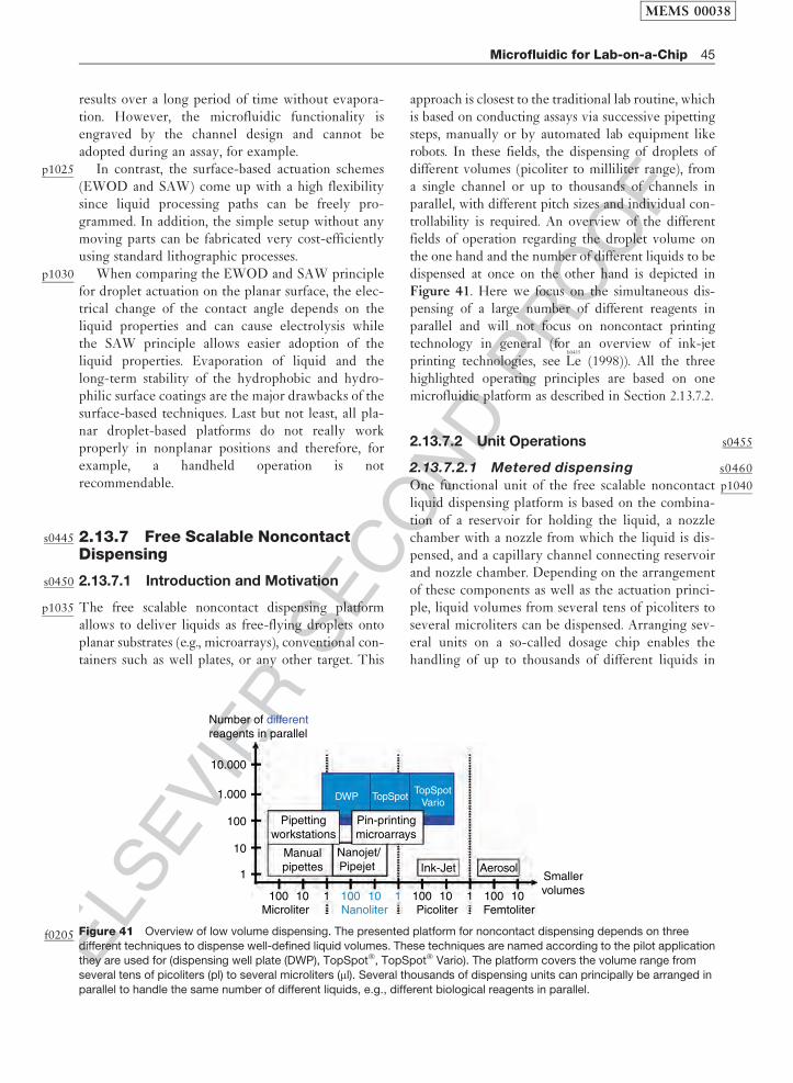
ELS
EVIE
RSEC
ON
DPR
OO
F
results over a long period of time without evapora-tion. However, the microfluidic functionality isengraved by the channel design and cannot beadopted during an assay, for example.
p1025 In contrast, the surface-based actuation schemes(EWOD and SAW) come up with a high flexibilitysince liquid processing paths can be freely pro-grammed. In addition, the simple setup without anymoving parts can be fabricated very cost-efficientlyusing standard lithographic processes.
p1030 When comparing the EWOD and SAW principlefor droplet actuation on the planar surface, the elec-trical change of the contact angle depends on theliquid properties and can cause electrolysis whilethe SAW principle allows easier adoption of theliquid properties. Evaporation of liquid and thelong-term stability of the hydrophobic and hydro-philic surface coatings are the major drawbacks of thesurface-based techniques. Last but not least, all pla-nar droplet-based platforms do not really workproperly in nonplanar positions and therefore, forexample, a handheld operation is notrecommendable.
s0445 2.13.7 Free Scalable NoncontactDispensing
s0450 2.13.7.1 Introduction and Motivation
p1035 The free scalable noncontact dispensing platformallows to deliver liquids as free-flying droplets ontoplanar substrates (e.g., microarrays), conventional con-tainers such as well plates, or any other target. This
approach is closest to the traditional lab routine, whichis based on conducting assays via successive pipettingsteps, manually or by automated lab equipment likerobots. In these fields, the dispensing of droplets ofdifferent volumes (picoliter to milliliter range), froma single channel or up to thousands of channels inparallel, with different pitch sizes and individual con-trollability is required. An overview of the differentfields of operation regarding the droplet volume onthe one hand and the number of different liquids to bedispensed at once on the other hand is depicted inFigure 41. Here we focus on the simultaneous dis-pensing of a large number of different reagents inparallel and will not focus on noncontact printingtechnology in general (for an overview of ink-jetprinting technologies, see
b0435
Le (1998)). All the threehighlighted operating principles are based on onemicrofluidic platform as described in Section 2.13.7.2.
s04552.13.7.2 Unit Operations
s04602.13.7.2.1 Metered dispensing
p1040One functional unit of the free scalable noncontactliquid dispensing platform is based on the combina-tion of a reservoir for holding the liquid, a nozzlechamber with a nozzle from which the liquid is dis-pensed, and a capillary channel connecting reservoirand nozzle chamber. Depending on the arrangementof these components as well as the actuation princi-ple, liquid volumes from several tens of picoliters toseveral microliters can be dispensed. Arranging sev-eral units on a so-called dosage chip enables thehandling of up to thousands of different liquids in
10.000
1.000
Pipettingworkstations
DWP TopSpotTopSpot
Vario
Pin-printingmicroarrays
Manualpipettes
Nanojet/Pipejet Ink-Jet Aerosol
Smallervolumes100
Microliter Picoliter FemtoliterNanoliter100 100100 10 11 110 10 10
100
10
1
Number of different reagents in parallel
Figure 41f0205 Overview of low volume dispensing. The presented platform for noncontact dispensing depends on three
different techniques to dispense well-defined liquid volumes. These techniques are named according to the pilot applicationthey are used for (dispensing well plate (DWP), TopSpot�, TopSpot� Vario). The platform covers the volume range from
several tens of picoliters (pl) to several microliters (ml). Several thousands of dispensing units can principally be arranged in
parallel to handle the same number of different liquids, e.g., different biological reagents in parallel.
MEMS 00038
Microfluidic for Lab-on-a-Chip 45
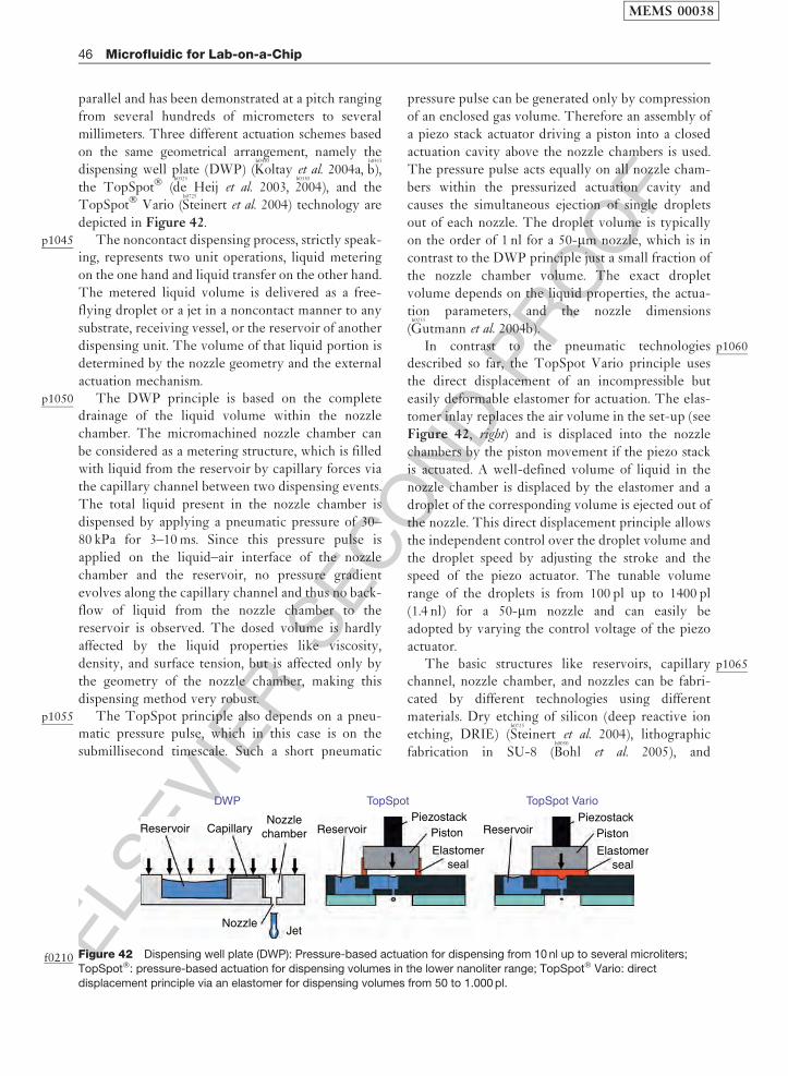
ELS
EVIE
RSEC
ON
DPR
OO
F
parallel and has been demonstrated at a pitch ranging
from several hundreds of micrometers to several
millimeters. Three different actuation schemes based
on the same geometrical arrangement, namely the
dispensing well plate (DWP) (b0410
Koltay et al. 2004a,b0415
b),
the TopSpot� (b0325
de Heij et al. 2003,b0330
2004), and the
TopSpot� Vario (b0725
Steinert et al. 2004) technology are
depicted in Figure 42.p1045 The noncontact dispensing process, strictly speak-
ing, represents two unit operations, liquid metering
on the one hand and liquid transfer on the other hand.
The metered liquid volume is delivered as a free-
flying droplet or a jet in a noncontact manner to any
substrate, receiving vessel, or the reservoir of another
dispensing unit. The volume of that liquid portion is
determined by the nozzle geometry and the external
actuation mechanism.p1050 The DWP principle is based on the complete
drainage of the liquid volume within the nozzle
chamber. The micromachined nozzle chamber can
be considered as a metering structure, which is filled
with liquid from the reservoir by capillary forces via
the capillary channel between two dispensing events.
The total liquid present in the nozzle chamber is
dispensed by applying a pneumatic pressure of 30–
80 kPa for 3–10 ms. Since this pressure pulse is
applied on the liquid–air interface of the nozzle
chamber and the reservoir, no pressure gradient
evolves along the capillary channel and thus no back-
flow of liquid from the nozzle chamber to the
reservoir is observed. The dosed volume is hardly
affected by the liquid properties like viscosity,
density, and surface tension, but is affected only by
the geometry of the nozzle chamber, making this
dispensing method very robust.p1055 The TopSpot principle also depends on a pneu-
matic pressure pulse, which in this case is on the
submillisecond timescale. Such a short pneumatic
pressure pulse can be generated only by compression
of an enclosed gas volume. Therefore an assembly of
a piezo stack actuator driving a piston into a closed
actuation cavity above the nozzle chambers is used.
The pressure pulse acts equally on all nozzle cham-
bers within the pressurized actuation cavity and
causes the simultaneous ejection of single droplets
out of each nozzle. The droplet volume is typically
on the order of 1 nl for a 50-mm nozzle, which is in
contrast to the DWP principle just a small fraction of
the nozzle chamber volume. The exact droplet
volume depends on the liquid properties, the actua-
tion parameters, and the nozzle dimensions
(b0255
Gutmann et al. 2004b).p1060In contrast to the pneumatic technologies
described so far, the TopSpot Vario principle uses
the direct displacement of an incompressible but
easily deformable elastomer for actuation. The elas-
tomer inlay replaces the air volume in the set-up (see
Figure 42, right) and is displaced into the nozzle
chambers by the piston movement if the piezo stack
is actuated. A well-defined volume of liquid in the
nozzle chamber is displaced by the elastomer and a
droplet of the corresponding volume is ejected out of
the nozzle. This direct displacement principle allows
the independent control over the droplet volume and
the droplet speed by adjusting the stroke and the
speed of the piezo actuator. The tunable volume
range of the droplets is from 100 pl up to 1400 pl
(1.4 nl) for a 50-mm nozzle and can easily be
adopted by varying the control voltage of the piezo
actuator.p1065The basic structures like reservoirs, capillary
channel, nozzle chamber, and nozzles can be fabri-
cated by different technologies using different
materials. Dry etching of silicon (deep reactive ion
etching, DRIE) (b0725
Steinert et al. 2004), lithographic
fabrication in SU-8 (b0050
Bohl et al. 2005), and
Reservoir ReservoirCapillary
DWP TopSpot TopSpot Vario
Nozzlechamber
PiezostackPiston
Elastomerseal
ReservoirPiezostack
Piston
Elastomerseal
NozzleJet
Figure 42f0210 Dispensing well plate (DWP): Pressure-based actuation for dispensing from 10 nl up to several microliters;
TopSpot�: pressure-based actuation for dispensing volumes in the lower nanoliter range; TopSpot� Vario: direct
displacement principle via an elastomer for dispensing volumes from 50 to 1.000 pl.
MEMS 00038
46 Microfluidic for Lab-on-a-Chip

ELS
EVIE
RSEC
ON
DPR
OO
F
micromilling of plastics (b0710
Steger et al. 2004) have beendemonstrated. A high precision in the geometry ofthe dispensing units is needed for a high precision ofthe dispensed liquid volumes, and this results in theneed for a high precision of the fabrication processes.
p1070 One unique feature of all the three dispensingprinciples described is the possibility to arrangemany of them in parallel with a free scalable pitchof the nozzle chambers and the reservoirs. The capil-lary channel that connects these two substructuresaccomplishes the format conversion from a reservoirpitch of a few millimeters (enabling the filling of thedispensing chip using standard pipetting robots) tothe pitch of the nozzle of a few hundred micrometers.This is important for the fabrication of microarrays,which is one application example for the platform,described in more detail in Section 2.13.7.3.1.
s0465 2.13.7.2.2 Incubation
p1075 Besides the noncontact dispensing of a meteredliquid volume, incubation steps at defined tempera-tures are also important for conducting biologicalassays. This can be realized on the free scalable non-contact dispensing platform by a reversible sealing ofthe structure openings, namely the nozzle, nozzlechamber, and the reservoirs preventing any liquidflow through the capillaries. The reservoirs and thenozzle chambers act as standard reaction cavities,then enabling incubation steps as long as the sealingis not removed (Figure 43, left).
s0470 2.13.7.2.3 Amplification
p1080 Similar to the incubation described in Section2.13.7.2.2, also temperature-initiated amplificationusing the polymerase chain reaction (PCR) methodcan be conducted within the cavities of the platform(Figure 43). Therefore, the sealed dispensing chip ismounted between an upper and a lower heatingplate, which perform a certain temperature cyclebetween three temperatures (94�C, 53�C, and
72�C). This process is similar to the common PCRcycling within standard well plates. However, for themicrocavities within the PCR slides the upper heat-ing plate also has to change the temperatureaccording to the cycling sequence in order to avoidtemperature gradients within the PCR solution.Within the microwell plate, the upper heat platecan be fixed at a high temperature (to prevent con-densation) since the air volume between the liquidand the heat plate acts as a thermal insulator. Whenthe cycling is finished the PCR product (amplifiedDNA) can be dispensed in nanoliter portions into amicroliter plate for further processing, onto a micro-array for detection, or into another dispensing chip.
s04752.13.7.3 Application Examples
s04802.13.7.3.1 TopSpot for microarray
spotting
p1085A DNA microarray is an ensemble of microscopicDNA spots attached to a flat solid surface forming anarray of different well-known capture molecules(probes) at well-defined positions. It can thereforebe considered as a highly parallel biosensor, basedon the lock and key principle. The probes on thesurface react with a complex mixture of molecules(sample) during the hybridization phase of a micro-array experiment. The sample molecules areequipped with fluorescent markers for later detectionin a fluorescent readout device. The position of apositive fluorescent signal provides informationabout the identity of the sample (Figure 44).
p1090The engineering challenge in the microarray fab-rication is to immobilize up to 1000 different analytesas spots of approximately 1 nl volume, with a pitch oftypically 500mm and below, at high quality, highthroughput, and low costs onto a substrate. One ofthe technical solutions to this problem is based on theTopSpot technology, a first application of the freescalable noncontact dispensing platform (
b0250
Gutmann
Nozzlechamber Capillary
Sealing
Nozzle
Reservoir
Upperheat plate
11.5
2
Lowerheat plate
Micro well plateDispensing platform (PCR slide)
104 ° C
–94 ° C–53 ° C –72 ° C
–94 °C –53 °C –72 °C
–94 °C –53 °C –72 °C
Figure 43f0215 The nozzle and the reservoir opening are sealed for incubation and amplification. Thermal cycling within the thin
substrate (polymerase chain reaction (PCR) slide) requires an equal temperature for the upper and the lower plate at any time.
Otherwise, inhomogeneous liquid temperatures can influence the assay performance.
MEMS 00038
Microfluidic for Lab-on-a-Chip 47
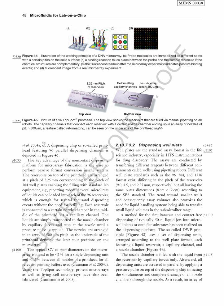
ELS
EVIE
RSEC
ON
DPR
OO
F
et al. 2004a,b0260
c). A dispensing chip or so-called print-head featuring 96 parallel dispensing channels isdepicted in Figure 45.
p1095 The key advantage of the noncontact dispensingplatform for microarray fabrication is the ease toperform passive format conversion in the system.The reservoirs on top of the printhead are arrangedat a pitch of 2.25 mm corresponding to the pitch of384 well plates enabling the filling with standard labequipment, e.g., pipetting robots. Several microlitersof liquids can be loaded into each of the 96 reservoirs,which is enough for several thousand dispensingevents without the need for refilling. Each reservoiris connected to a certain nozzle chamber in the mid-dle of the printhead via a capillary channel. Theliquids are simply transported to the nozzle chamberby capillary forces and stop at the nozzle until apressure pulse is applied. The nozzles are arrangedin an array of 500-mm pitch on the underside of theprinthead defining the later spot positions on themicroarray.
p1100 The typical CV of spot diameters on the micro-array is found to be <1% for a single dispensing unitand <1.5% between all nozzles of a printhead for allrelevant printing buffers used (
b0250
Gutmann et al. 2004a).Using the TopSpot technology, protein microarraysas well as living cell microarrays have also beenfabricated (
b0265
Gutmann et al. 2005).
s04852.13.7.3.2 Dispensing well plate
p1105Well plates are the standard assay format in the lifescience industry, especially in HTS instrumentationsfor drug discovery. The assays are conducted bytransferring different reagents between different con-tainments called wells using pipetting robots. Differentwell plate standards such as the 96, 384, and 1536format exist, differing in the pitch of the reservoirs(9.0, 4.5, and 2.25 mm, respectively) but all having thesame outer dimensions (8 cm� 12 cm) according tothe SBS standard. The trend toward smaller wellsand consequently assay volumes also provokes theneed for liquid handling systems being able to transfersmall liquid volumes in the submicroliter range.
p1110A method for the simultaneous and contact-freedispensing of typically 50-nl liquid jets into micro-well plates or onto flat substrates has been realized onthe dispensing platform. The so-called DWP prin-ciple (Figure 42) uses a set of dispensing units,arranged according to the well plate format, eachfeaturing a liquid reservoir, a capillary channel, anda nozzle chamber (Figure 46).
p1115The nozzle chamber is filled with the liquid fromthe reservoir by capillary forces only. Afterward, alldispensing units are actuated in parallel by applying apressure pulse on top of the dispensing chip initiatingthe simultaneous and complete drainage of all nozzlechambers through the nozzle. As a result, an array of
2.25 mm Pitchof reservoirs
Reformattingcapillary channels
Top view Bottom view
Nozzle array(pitch: 500 μm)
Figure 45f0225 Picture of a 96 TopSpot� printhead. The top view shows the reservoirs that are filled via manual pipetting or lab
robots. The capillary channels that connect each reservoir with a certain nozzle chamber ending up in an array of nozzles of
pitch 500mm, a feature called reformatting, can be seen on the underside of the printhead (right).
(a) (b) (c) (d)
Figure 44f0220 Illustration of the working principle of a DNA microarray. (a) Probe molecules are immobilized as different spots
with a certain pitch on the solid surface; (b) a binding reaction takes place between the probe and the sample molecule if the
chemical structures are complementary; (c) the fluorescent readout after the microarray experiment indicates positive bindingevents; and (d) fluorescent image from a real microarray experiment.
MEMS 00038
48 Microfluidic for Lab-on-a-Chip
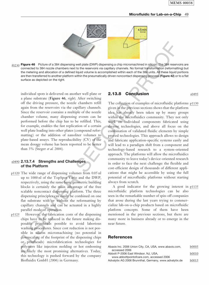
ELS
EVIE
RSEC
ON
DPR
OO
F
individual spots is delivered on another well plate ora plane substrate (Figure 46, right). After switchingoff the driving pressure, the nozzle chambers refillagain from the reservoirs via the capillary channels.Since the reservoir contains a multiple of the nozzlechamber volume, many dispensing events can beperformed before the chip has to be refilled. This,for example, enables the fast replication of a certainwell plate loading into other plates (compound refor-matting) or the addition of nanoliter volumes toplate-based assays. The reproducibility (CV) of themean dosage volume has been reported to be betterthan 3% (
b0710
Steger et al. 2004).
s0490 2.13.7.4 Strengths and Challengesof the Platform
p1120 The wide range of dispensing volumes from 0.05 nlup to 1000 nl of the TopSpot Vario and the DWP,respectively, using the same basic geometric buildingblocks is certainly the main advantage of the freescalable noncontact dispensing platform. The threedispensing principles can easily be combined on oneflat substrate with or without the reformatting bycapillary channels and can be actuated in a highlyparallel mode of operation.
p1125 However, the fabrication costs of the dispensingchips have to be reduced in the future making dis-posable printheads possible to avoid laboriouswashing procedures. Since cost reduction is not pos-sible in silicon micromachining (no potential indownscaling of the footprint of the dispensing chipsor printheads) microfabrication technologies forpolymers like injection molding or hot embossingare likely the most promising alternatives. Today,this technology is pushed forward by the companyBiofluidix GmbH (2006) in Germany.
s04952.13.8 Conclusion
p1130The collection of examples of microfluidic platformsgiven in the previous sections shows that the platformidea has already been taken up by many groupswithin the microfluidics community. They not onlywork on individual components fabricated usingdiverse technologies, and above all focus on thecombination of validated fluidic elements by simpleproved technologies. This approach allows to designand fabricate application-specific systems easily andwill lead to a paradigm shift from a component andtechnology-based research to a system-orientedapproach. The platforms will allow the microfluidicscommunity to leave today’s device-oriented researchin order to face the next challenge: the flexible andcost-efficient design of thousands of different appli-cations that might be accessible by using the fullpotential of microfluidic platforms without startingalways from scratch.
p1135A good indicator for the growing interest inmicrofluidic platform technologies can be alsoseen in the remarkable number of spin-off companiesthat arose during the last years trying to commer-cialize lab-on-a-chip products based on microfluidicplatform concepts. Some of them have beenmentioned in the previous sections, but there aremany more in business already or to emerge in thenear future.
References
b0005Abaxis Inc. 2006 Union City, CA, USA, www.abaxis.com,accessed 2006
b0010Abbott P-2006 East Windsor, NJ, USA,www.abbottpointofcare.com, accessed 2006
b0015Advalytix AG 2006 Brunnthal, Germany, www.advalytix.de
4.5 mm
Figure 46f0230 Picture of a 384 dispensing well plate (DWP) dispensing a chip micromachined in silicon. The 384 reservoirs are
connected to 384 nozzle chambers next to the reservoirs via capillary channels. No format transformation (reformatting) but
the metering and allocation of a defined liquid volume is accomplished within each of the 384 units. All these liquid portionsare then transferred to another platform within the pneumatically driven noncontact dispensing process (Figure 42) or to a flat
surface as depicted on the right.
MEMS 00038
Microfluidic for Lab-on-a-Chip 49

ELS
EVIE
RSEC
ON
DPR
OO
F
b0020 Anderson N G 1969 Computer interfaced fast analyzers.Science 166, 317–24
b0025 Andersson H, van den Berg A 2004 Lab-on-Chips for Cellomics,Micro and Nanotechnologies for Life Science. KluwerAcademic Publishers, Dordrecht, The Netherlands
b0030 Anna S L, Bontoux N, Stone H A 2003 Formation of dispersionsusing ‘‘flow focusing’’ in microchannels. Appl. Phys. Lett. 82,364–6
b0035 Auroux P A, Iossifidis D, Reyes D R, Manz A 2002 Micro totalanalysis systems. 2. Analytical standard operations andapplications. Anal. Chem. 74, 2637–52
b0040 Berthier J, Clementz P, Raccurt O, Jary D, Claustre P,Peponnet C, Fouillet Y 2006 Computer aided designof an EWOD microdevice. Sens. Actuators A Phys. 127,283–94
b0045 Bioluidix GmbH 2006 Freiburg, Germany,www.biofluidix.com
b0050 Bohl B, Steger R, Zengerle R, Koltay P 2005 Multi-layer SU-8lift-off technology for microfluidic devices. J. Micromech.Microeng. 15, 1125–30
b0055 Brenner T, Glatzel T, Zengerle R, Ducree J 2005 Frequency-dependent transversal flow control in centrifugalmicrofluidics. Lab Chip 5, 146–50
b0060 Bringer M R, Gerdts C J, Song H, Tice J D, Ismagilov R F 2004Microfluidic systems for chemical kinetics that rely onchaotic mixing in droplets. Philos. Trans. R. Soc. Lond. AMath. Phys. Eng. Sci. 362, 1087–104
b0065 Burns M A, Johnson B N, Brahmasandra S N, Handique K,Webster J R, Krishnan M, Sammarco T S, Man P M, Jones D,Heldsinger D, Mastrangelo C H, Burke D T 1998 Anintegrated nanoliter DNA analysis device. Science 282,484–7
b0070 Burtis C A, Anderson N G, Mailen J C, Scott C D, Tiffany T O,Johnson W F 1972 Development of a miniature fast analyzer.Clin. Chem. 18, 753–61
b0075 Chatterjee D, Hetayothin B, Wheeler A R, King D J, Garrell R L2006 Droplet-based microfluidics with nonaqueous solventsand solutions. Lab Chip 6, 199–206
b0080 Chen D L, Gerdts C J, Ismagilov R F 2005 Using microfluidics toobserve the effect of mixing on nucleation of protein crystals.J. Am. Chem. Soc. 127, 9672–3
b0085 Chen D L L, Ismagilov R F 2006 Microfluidic cartridgespreloaded with nanoliter plugs of reagents: An alternative to96-well plates for screening. Curr. Opin. Chem. Biol. 10,226–31
b0090 Chen H, Meiners J C 2004 Topologic mixing on a microfluidicchip. Appl. Phys. Lett. 84, 2193–5
b0095 Cheng Y T, Lin L W, Najafi K 2001 A hermetic glass-siliconpackage formed using localized aluminum/silicon-glassbonding. J. Microelectromech. Syst. 10, 392–9
b0100 Cho S K, Moon H J, Kim C J 2003 Creating, transporting,cutting, and merging liquid droplets by electrowetting-basedactuation for digital microfluidic circuits. J.Microelectromech. Syst. 12, 70–80
b0105 Chou H P, Unger M A, Quake S R 2001 A microfabricated rotarypump. Biomed. Microdevices 3, 323–30
b0110 Clark T J, McPherson P H, Buechler K F 2002 The triage cardiacpanel. Point Care 1, 42–6
b0115 Delamarche E, Bernard A, Schmid H, Michel B, Biebuyck H1997 Patterned delivery of immunoglobulins to surfacesusing microfluidic networks. Science 276, 779–81
b0120 deMello A J 2003 Microfluidics – DNA amplification moves on.Nature 422, 28–9
b0125 Dendukuri D, Tsoi K, Hatton T A, Doyle P S 2005 Controlledsynthesis of nonspherical microparticles using microfluidics.Langmuir 21, 2113–16
b0130 Ducree J, Zengerle R 2004 FlowMap – Microfluidics Roadmapfor the Life Sciences. Books on Demand GmbH,Norderstedt, Germany
b0135Ducree J, Haeberle S, Brenner T, Glatzel T, Zengerle R 2005Patterning of flow and mixing in rotating radialmicrochannels. Microfluidics Nanofluidics 2, 97–105
b0140Ducree J, Brenner T, Haeberle S, Glatzel T, Zengerle R 2006Multilamination of flows in planar networks of rotatingmicrochannels. Microfluidics Nanofluidics 2, 78–84
b0145Duffy D C, McDonald J C, Schueller O J A, Whitesides G M 1998Rapid prototyping of microfluidic systems inpoly(dimethylsiloxane). Anal. Chem. 70, 4974–84
b0150Duffy D C, Gillis H L, Lin J, Sheppard N F Jr., Kellogg G J 1999Microfabricated centrifugal microfluidic systems:Characterization and multiple enzymatic assays. Anal.Chem. 71, 4669–78
b0155Effenhauser C S, Manz A, Widmer H M 1993 Glass chips forhigh-speed capillary electrophoresis separations withsubmicrometer plate heights. Anal. Chem. 65, 2637–42
b0160Effenhauser C S, Bruin G J M, Paulus A, Ehrat M 1997Integrated capillary electrophoresis on flexible siliconemicrodevices: Analysis of DNA restriction fragments anddetection of single DNA molecules on microchips. Anal.Chem. 69, 3451–7
b0165Ehrfeld W, Golbig K, Hessel V, Lowe H, Richter T 1999Characterization of mixing in micromixers by a test reaction:Single mixing units and mixer arrays. Ind. Eng. Chem. Res.38, 1075–82
b0170Ekstrand G, Thorsen T 2005 Liquid router. US 2005/0141344 A1b0175Ekstrand G, Holmquist C, Orlefors A E, Hellman B, Larsson A,
Andersson P 2000 Microfluidics in a rotating CD. In: Van denBerg A, Olthius W, and Bergveld P (eds.) Proc. Micro TotalAnalysis Systems 2000, Enschede, The Netherlands, pp. 311–14
b0180Erickson D 2005 Towards numerical prototyping oflabs-on-chip: Modeling for integrated microfluidic devices.Microfluidics Nanofluidics 1, 301–18
b0185Fluidigm Corporation 2006 San Francisco, USA,www.fluidigm.com, accessed 2006
b0190Fredrickson C K, Fan Z H 2004 Macro-to-micro interfaces formicrofluidic devices. Lab Chip 4, 526–33
b0195Fu A Y, Spence C, Scherer A, Arnold F H, Quake S R 1999 Amicrofabricated fluorescence-activated cell sorter. Nat.Biotechnol. 17, 1109–11
b0200Garstecki P, Gitlin I, DiLuzio W, Whitesides G M, Kumacheva E,Stone H A 2004 Formation of monodisperse bubbles in amicrofluidic flow-focusing device. Appl. Phys. Lett. 85,2649–51
b0205Garstecki P, Fischbach M A, Whitesides G M 2005a Design formixing using bubbles in branched microfluidic channels.Appl. Phys. Lett. 86, 244108
b0210Garstecki P, Stone H A, Whitesides G M 2005b Mechanism forflow-rate controlled breakup in confined geometries: A routeto monodisperse emulsions. Phys. Rev. Lett. 94, 164501
b0215Gascoyne P R C, Vykoukal J V, Schwartz J A, Anderson T J,Vykoukal D M, Current K W, McConaghy C, Becker F F,Andrews C 2004 Dielectrophoresis-based programmablefluidic processors. Lab Chip 4, 299–309
b0220Geschke O, Klank H, Telleman P 2004 Microsystem Engineeringof Lab-on-a-Chip Devices. Wiley-VCH, Weinheim
b0225Goettsche T, Wolff A 2006 IntelliDrug – An integrated intelligentoral drug delivery system. mst-news 06, 36–7
b0230Gravesen P, Braneberg J, Jensen O S 1993 Microfluidics – Areview. J. Micromech. Microeng. 3, 168–82
b0235Grumann M, Geipel A, Riegger L, Zengerle R, Ducree J 2005Batch-mode mixing on centrifugal microfluidic platforms.Lab Chip 5, 560–5
b0240Gunther A, Khan S A, Thalmann M, Trachsel F, Jensen K F 2004Transport and reaction in microscale segmented gas–liquidflow. Lab Chip 4, 278–86
b0245Gunther A, Jhunjhunwala M, Thalmann M, Schmidt M A, JensenK F 2005 Micromixing of miscible liquids in segmented gas–liquid flow. Langmuir 21, 1547–55
MEMS 00038
50 Microfluidic for Lab-on-a-Chip

ELS
EVIE
RSEC
ON
DPR
OO
F
b0250 Gutmann O, Kuehlewein R, Reinbold S, Niekrawietz R, SteinertC P, De H B, Zengerle R, Daub M 2004a A highly parallelnanoliter dispenser for microarray fabrication. Biomed.Microdevices 6, 131–7
b0255 Gutmann O, Niekrawietz R, Kuehlewein R, Steinert C P, de HeijB, Zengerle R, Daub M 2004b Impact of medium propertieson droplet release in a highly parallel nanoliter dispenser.Sens. Actuators A Phys. 116, 187–94
b0260 Gutmann O, Niekrawietz R, Kuehlewein R, Steinert C P,Reinbold S, De H B, Daub M, Zengerle R 2004c Non-contactproduction of oligonucleotide microarrays using the highlyintegrated TopSpot nanoliter dispenser. Analyst 129, 835–40
b0265 Gutmann O, Kuehlewein R, Reinbold S, Niekrawietz R, SteinertC P, de Heij B, Zengerle R, Daub M 2005 Fast and reliableprotein microarray production by a new drop-in-droptechnique. Lab Chip 5, 675–81
b0270 Guttenberg Z, Muller H, Habermuller H, Geisbauer A, Pipper J,Felbel J, Kielpinski M, Scriba J, Wixforth A 2005 Planar chipdevice for PCR and hybridization with surface acoustic wavepump. Lab Chip 5, 308–17
b0275 GYROS AB 2006 Uppsala, Sweden, www.gyros.com accessed2006
b0280 Haeberle S, Brenner T, Schlosser H P, Zengerle R, Ducree J2005 Centrifugal micromixer. Chem. Eng. Tech. 28, 613–16
b0285 Haeberle S, Brenner T, Zengerle R, Ducree J 2006a Centrifugalextraction of plasma from whole blood on a rotating disk.Lab Chip 6, 776–81
b0290 Haeberle S, Naegele L, Zengerle R, Ducree J 2006b A DigitalCentrifugal Droplet Switch For Routing of Liquids. In:Kitamori T, Fujita H, Hasebe S (eds), Proceedings of mTAS2006, November 5–9, Tokyo, Japan, pp. 570–2.
b0295 Haeberle S, Zengerle R, Ducree J 2007 Centrifugal generationand manipulation of droplet emulsions. MicrofluidicsNanofluidics 3, 65–75
b0300 Hansen C, Quake S R 2003 Microfluidics in structural biology:Smaller, faster� � � better. Curr. Opin. Struct. Biol. 13, 538–44
b0305 Hansen C L, Skordalakes E, Berger J M, Quake S R 2002 Arobust and scalable microfluidic metering method thatallows protein crystal growth by free interface diffusion.Proc. Natl. Acad. Sci. USA 99, 16531–6
b0310 Harrison D J, Manz A, Fan Z H, Ludi H, Widmer H M 1992Capillary electrophoresis and sample injection systemsintegrated on a planar glass chip. Anal. Chem. 64, 1926–32
b0315 Harrison D J, Fluri K, Seiler K, Fan Z H, Effenhauser C S, Manz A1993 Micromachining – A miniaturized capillaryelectrophoresis-based chemical-analysis system on a chip.Science 261, 895–7
b0320 He M Y, Edgar J S, Jeffries G D M, Lorenz R M, Shelby J P, ChiuD T 2005 Selective encapsulation of single cells andsubcellular organelles into picoliter- and femtoliter-volumedroplets. Anal. Chem. 77, 1539–44
b0325 de Heij B, Steinert C, Sandmaier H, Zengerle R 2003 A tunableand highly-parallel picolitre-dispenser based on direct liquiddisplacement. Sens. Actuators A Phys. 103, 88–92
b0330 de Heij B, Daub M, Gutmann O, Niekrawietz R, Sandmaier H,Zengerle R 2004 Highly parallel dispensing of chemical andbiological reagents. Anal. Bioanal. Chem. 378, 119–22
b0335 Hessel V, Hardt S, Lowe H, Schonfeld F 2003 Laminar mixing indifferent interdigital micromixers: I. Experimentalcharacterization. AIChE J. 49, 566–77
b0340 Hessel V, Lowe H, Schonfeld F 2005 Micromixers – A review onpassive and active mixing principles. Chem. Eng. Sci. 60,2479–501
b0345 Honda N, Lindberg U, Andersson P, Hoffman S, Takei H 2005Simultaneous multiple immunoassays in a compact disc-shaped microfluidic device based on centrifugal force. Clin.Chem. 51, 1955–61
b0350 Hong J W, Quake S R 2003 Integrated nanoliter systems. Nat.Biotechnol. 21, 1179–83
b0355Hong J W, Studer V, Hang G, Anderson W F, Quake S R 2004 Ananoliter-scale nucleic acid processor with parallelarchitecture. Nat. Biotechnol. 22, 435–9
b0360Hosokawa K, Fujii T, Endo I 1999 Handling of picoliter liquidsamples in a poly(dimethylsiloxane)-based microfluidicdevice. Anal. Chem. 71, 4781–5
b0365Huang L R, Cox E C, Austin R H, Sturm J C 2004 Continuousparticle separation through deterministic lateraldisplacement. Science 304, 987–90
b0370Jandik P, Weigl B H, Kessler N, Cheng J, Morris C J, Schulte T,Avdalovic N 2002 Initial study of using a laminar fluid diffusioninterface for sample preparation in high-performance liquidchromatography. J. Chromatogr. A 954, 33–40
b0375Jiang F, Drese K S, Hardt S, Kupper M, Schonfeld F 2004Helical flows and chaotic mixing in curved micro channels.AIChE J. 50, 2297–305
b0380Joanicot M, Ajdari A 2005 Applied physics – Droplet control formicrofluidics. Science 309, 887–8
b0385Johnson T J, Ross D, Locascio L E 2002 Rapid microfluidicmixing. Anal. Chem. 74, 45–51
b0390Kamholz A E 2004 Proliferation of microfluidics in literature andintellectual property. Lab Chip 4, 16N–20N
b0395Khan S A, Gunther A, Schmidt M A, Jensen K F 2004Microfluidic synthesis of colloidal silica. Langmuir 20,8604–11
b0400Knight J B, Vishwanath A, Brody J P, Austin R H 1998Hydrodynamic focusing on a silicon chip: Mixing nanolitersin microseconds. Phys. Rev. Lett. 80, 3863–6
b0405Kobayashi I, Mukataka S, Nakajima M 2005 Effects of type andphysical properties of oil phase on oil-in-water emulsiondroplet formation in straight-through microchannelemulsification, experimental and CFD studies. Langmuir 21,5722–30
b0410Koltay P, Kalix J, Zengerle R 2004a Theoretical evaluation of thedispensing well plate method (DWP part II). Sens. ActuatorsA Phys. 116, 472–82
b0415Koltay P, Steger R, Bohl B, Zengerle R 2004b The dispensingwell plate: A novel nanodispenser for the multiparalleldelivery of liquids (DWP Part I). Sens. Actuators A Phys. 116,483–91
b0420Kopp M U, de Mello A J, Manz A 1998 Chemical amplification:Continuous-flow PCR on a chip. Science 280, 1046–8
b0425Lai S, Wang S, Luo J, Lee L J, Yang S T, Madou M J 2004 Designof a compact disk-like microfluidic platform for enzyme-linked immunosorbent assay. Anal. Chem. 76, 1832–7
b0430Laser D J, Santiago J G 2004 A review of micropumps. J.Micromech. Microeng. 14, R35–64
b0435Le H P 1998 Progress and trends in ink-jet printing technology.J. Imaging Sci. Technol. 42, 49–62
b0440Lee G B, Hung C I, Ke B J, Huang G R, Hwei B H 2001aMicromachined pre-focused 1�N flow switches forcontinuous sample injection. J. Micromech. Microeng. 11,567–73
b0445Lee G B, Hwei B H, Huang G R 2001b Micromachined pre-focused M�N flow switches for continuous multi-sampleinjection. J. Micromech. Microeng. 11, 654–61
b0450Lee J, Kim C J 2000 Surface-tension-driven microactuationbased on continuous electrowetting. J. Microelectromech.Syst. 9, 171–80
b0455Lee J, Moon H, Fowler J, Schoellhammer T, Kim C J 2002Electrowetting and electrowetting-on-dielectric formicroscale liquid handling. Sens. Actuators A Phys. 95,259–68
b0460Li P C H 2006 Microfluidic Lab-on-a-Chip for Chemical andBiological Analysis and Discovery. Taylor & Francis Group,Boca Raton, FL
b0465Link D R, Anna S L, Weitz D A, Stone H A 2004 Geometricallymediated breakup of drops in microfluidic devices. Phys.Rev. Lett. 92, 054503
MEMS 00038
Microfluidic for Lab-on-a-Chip 51
ELS
EVIE
RSEC
ON
DPR
OO
F
b0470 Lion N, Rohner T C, Dayon L, Arnaud I L, Damoc E, YouhnovskiN, Wu Z Y, Roussel C, Josserand J, Jensen H, Rossier J S,Przbylski M, Girault H H 2003 Microfluidic systems inproteomics. Electrophoresis 24, 3533–62
b0475 Liu J, Hansen C, Quake S R 2003 Solving the ‘‘world-to-chip’’interface problem with a microfluidic matrix. Anal. Chem. 75,4718–23
b0480 Lotters J C, Olthuis W, Veltink P H, Bergveld P 1997 Themechanical properties of the rubber elastic polymerpolydimethylsiloxane for sensor applications. J. Micromech.Microeng. 7, 145–7
b0485 Madou M, Kellogg G J 1998 The LabCD: A centrifuge-basedmicrofluidic platform for diagnostics. Proc. SPIE 3259,80–93, Systems and technologies for clinical diagnosticsand drug discovery
b0490 Madou M, Lee J, Daunert S, Lai S, Shih C-H 2001 Designand fabrication of CD-like microfluidic platforms fordiagnostics: Microfluidic functions. Biomed. Microdevices3, 245–54
b0495 Manz A, Graber N, Widmer H M 1990a Miniaturized totalchemical-analysis system – A novel concept for chemicalsensing. Sens. Actuators B Chem. 1, 244–8
b0500 Manz A, Miyahara Y, Miura J, Watanabe Y, Miyagi H, Sato K1990b Design of an open-tubular column liquidchromatograph using silicon chip technology. Sens.Actuators B Chem. 1, 249–55
b0505 Manz A, Harrison D J, Verpoorte E M J, Fettinger J C, Paulus A,Ludi H, Widmer H M 1992 Planar chips technology forminiaturization and integration of separation techniques intomonitoring systems – Capillary electrophoresis on a chip. J.Chromatogr. 593, 253–8
b0510 Marcus J S, Anderson W F, Quake S R 2006a Microfluidicsingle-cell mRNA isolation and analysis. Anal. Chem. 78,3084–9
b0515 Marcus J S, Anderson W F, Quake S R 2006b Parallel picoliterRT-PCR assays using microfluidics. Anal. Chem. 78, 956–8
b0520 Marko-Varga G, Nilsson J, Laurell T 2003 New directions ofminiaturization within the proteomics research area.Electrophoresis 24, 3521–32
b0525 Martin K, Henkel T, Baier V, Grodrian A, Schon T, Roth M,Kohler J M, Metze J 2003 Generation of larger numbers ofseparated microbial populations by cultivation insegmented-flow microdevices. Lab Chip 3, 202–7
b0530 de Mello A J, Beard N 2003 Dealing with ‘real’ samples: Samplepre-treatment in microfluidic systems. Lab Chip 3, 11N–19N
b0535 Micronics Inc. 2006 Redmond, WA, USA, www.micronics.net,accessed 2006
b0540 Mugele F, Baret J C 2005 Electrowetting: From basics toapplications. J. Phys. Condens. Matter 17, R705–74
b0545 Mugele F, Klingner A, Buehrle J, Steinhauser D, Herminghaus S2005 Electrowetting: A convenient way to switchablewettability patterns. J. Phys. Condens. Matter 17, S559–76
b0550 Nguyen N T, Wereley S T 2002 Fundamentals and Applicationsof Microfluidics. Artech House Books, Boston, MA
b0555 Nguyen N T, Wu Z G 2005 Micromixers – A review. J.Micromech. Microeng. 15, R1–16
b0560 Nisisako T, Torii T, Higuchi T 2002 Droplet formation in amicrochannel network. Lab Chip 2, 24–6
b0565 Oh K W, Ahn C H 2006 A review of microvalves. J. Micromech.Microeng. 16, R13–39
b0570 Okushima S, Nisisako T, Torii T, Higuchi T 2004 Controlledproduction of monodisperse double emulsions by two-stepdroplet breakup in microfluidic devices. Langmuir 20,9905–8
b0575 Oosterbroek R E, van den Berg A 2003 Lab-on-a-Chip:Miniaturized Systems for (Bio)Chemical Analysis andSynthesis. Elsevier Science, Amsterdam
b0580 Paik P, Pamula V K, Fair R B 2003a Rapid droplet mixers fordigital microfluidic systems. Lab Chip 3, 253–9
b0585Paik P, Pamula V K, Pollack M G, Fair R B 2003b Electrowetting-based droplet mixers for microfluidic systems. Lab Chip 3,28–33
b0590Pollack M G, Fair R B, Shenderov A D 2000 Electrowetting-based actuation of liquid droplets for microfluidicapplications. Appl. Phys. Lett. 77, 1725–6
b0595Pollack M G, Shenderov A D, Fair R B 2002 Electrowetting-based actuation of droplets for integrated microfluidics. LabChip 2, 96–101
b0600Quake S R, Scherer A 2000 From micro- to nanofabrication withsoft materials. Science 290, 1536–40
b0605Raschke G 2005 Molekulare Erkennung mit einzelnen Gold-Nanopartikeln. PhD-thesis, TU Muenchen
b0610Ren H, Fair R B, Pollack M G 2004 Automated on-chip dropletdispensing with volume control by electro-wetting actuationand capacitance metering. Sens. Actuators B Chem. 98,319–27
b0615Reyes D R, Iossifidis D, Auroux P A, Manz A 2002 Micro totalanalysis systems. 1. Introduction, theory, and technology.Anal. Chem. 74, 2623–36
b0620Roach L S, Song H, Ismagilov R F 2005 Controlling nonspecificprotein adsorption in a plug-based microfluidic system bycontrolling interfacial chemistry using fluorous-phasesurfactants. Anal. Chem. 77, 785–96
b0625Roche 2006 Basel, CH, www.roche.com, accessed 2006b0630Salemme F R 1972 Free interface diffusion technique for
crystallization of proteins for X-ray crystallography. Arch.Biochem. Biophys. 151, 533–9
b0635Schembri C T, Ostoich V, Lingane P J, Burd T L, Buhl S N 1992Portable simultaneous multiple analyte whole-bloodanalyzer for point-of-care testing. Clin. Chem. 38, 1665–70
b0640Schembri C T, Burd T L, Kopfsill A R, Shea L R, Braynin B 1995Centrifugation and capillarity integrated into a multipleanalyte whole-blood analyzer. J. Automatic Chem. 17,99–104
b0645Schonfeld F, Hessel V, Hofmann C 2004 An optimised split-and-recombine micro-mixer with uniform ‘chaotic’ mixing.Lab Chip 4, 65–9
b0650Schwartz J A, Vykoukal J V, Gascoyne P R C 2004 Droplet-based chemistry on a programmable micro-chip. Lab Chip 4,11–17
b0655Shestopalov I, Tice J D, Ismagilov R F 2004 Multi-step synthesisof nanoparticles performed on millisecond time scale in amicrofluidic droplet-based system. Lab Chip 4, 316–21
b0660Shoji S, Esashi M 1994 Microflow devices and systems. J.Micromech. Microeng. 4, 157–71
b0665Shoji S, Esashi M, Matsuo T 1988 Prototype miniature blood-gas analyzer fabricated on a silicon-wafer. Sens. Actuators14, 101–7
b0670Sia S K, Whitesides G M 2003 Microfluidic devices fabricated inpoly(dimethylsiloxane) for biological studies. Electrophoresis24, 3563–76
b0675Song H, Ismagilov R F 2003 Millisecond kinetics on amicrofluidic chip using nanoliters of reagents. J. Am. Chem.Soc. 125, 14613–19
b0680Song H, Bringer M R, Tice J D, Gerdts C J, Ismagilov R F 2003aExperimental test of scaling of mixing by chaotic advection indroplets moving through microfluidic channels. Appl. Phys.Lett. 83, 4664–6
b0685Song H, Tice J D, Ismagilov R F 2003b A microfluidic system forcontrolling reaction networks in time. Angew. Chem. Int. Ed.42, 768–72
b0690Song Y J, Zhao T S 2001 Modelling and test of a thermally-driven phase-change nonmechanical micropump. J.Micromech. Microeng. 11, 713–19
b0695SpinX Technologies 2006 Geneva, Switzerland,www.spinx-technologies.com accessed 2006
b0700Squires T M, Quake S R 2005 Microfluidics: Fluid physics at thenanoliter scale. Rev. Mod. Phys. 77, 977–1026
MEMS 00038
52 Microfluidic for Lab-on-a-Chip

ELS
EVIE
RSEC
ON
DPR
OO
F
b0705 Srinivasan V, Pamula V K, Fair R B 2004 An integrated digitalmicrofluidic lab-on-a-chip for clinical diagnostics on humanphysiological fluids. Lab Chip 4, 310–15
b0710 Steger R, Bohl B, Zengerle R, Koltay P 2004 The dispensingwell plate: A novel device for nanoliter liquid handling inultra high-throughput screening. J. Assoc. Lab. Autom. 9,291–9
b0715 Steigert J, Grumann M, Brenner T, Mittenbuhler K, Nann T,Ruhe J, Moser I, Haeberle S, Riegger L, Riegler J, BesslerW, Zengerle R, Ducree J 2005 Integrated samplepreparation, reaction, and detection on a high-frequencycentrifugal microfluidic platform. J. Assoc. Lab. Autom. 10,331–41
b0720 Steigert J, Grumann M, Brenner T, Riegger L, Harter J,Zengerle R, Ducree J 2006 Fully integrated whole bloodtesting by real-time absorption measurement on acentrifugal platform. Lab Chip 6, 1040–4
b0725 Steinert C P, Goutier I, Gutmann O, Sandmaier H, Daub M, deHeij B, Zengerle R 2004 A highly parallel picoliter dispenserwith an integrated, novel capillary channel structure. Sens.Actuators A Phys. 116, 171–7
b0730 Steinert C P, Mueller-Dieckmann J, Weiss M, Roessle M,Zengerle R, Koltay P 2007 Miniaturized and highly parallelprotein crystallization on a microfluidic disc. Proceedings ofthe IEEE MEMS 2007, January 21–25, Kobe, Japan, pp. 561–4
b0735 Stone H A, Stroock A D, Ajdari A 2004 Engineering flows in smalldevices: Microfluidics toward a lab-on-a-chip. Annu. Rev.Fluid Mech. 36, 381–411
b0740 Stroock A D, Dertinger S K W, Ajdari A, Mezic I, Stone H A,Whitesides G M 2002 Chaotic mixer for microchannels.Science 295, 647–51
b0745 Sudarsan A P, Ugaz V M 2006 Fluid mixing in planar spiralmicrochannels. Lab Chip 6, 74–82
b0750 Sugiura S, Nakajima M, Iwamoto S, Seki M 2001 Interfacialtension driven monodispersed droplet formation frommicrofabricated channel array. Langmuir 17, 5562–6
b0755 Takagi J, Yamada M, Yasuda M, Seki M 2005 Continuousparticle separation in a microchannel having asymmetricallyarranged multiple branches. Lab Chip 5, 778–84
b0760 Tay F E H 2002 Microfluidics and BioMEMS Applications.Kluwer Academic Publishers, Boston, MA
b0765 Terry S C, Jerman J H, Angell J B 1979 Gas-chromatographicair analyzer fabricated on a silicon-wafer. IEEE Trans.Electron Devices 26, 1880–6
b0770 Thorsen T, Maerkl S J, Quake S R 2002 Microfluidic large-scaleintegration. Science 298, 580–4
b0775 Tice J D, Song H, Lyon A D, Ismagilov R F 2003 Formation ofdroplets and mixing in multiphase microfluidics at low valuesof the Reynolds and the capillary numbers. Langmuir 19,9127–33
b0780 Tice J D, Lyon A D, Ismagilov R F 2004 Effects of viscosity ondroplet formation and mixing in microfluidic channels. Anal.Chim. Acta 507, 73–7
b0785 Unger M A, Chou H P, Thorsen T, Scherer A, Quake S R 2000Monolithic microfabricated valves and pumps by multilayersoft lithography. Science 288, 113–16
b0790 Urban G A 2006 BioMEMS. Springer, Berlinb0795 Utada A S, Lorenceau E, Link D R, Kaplan P D, Stone H A, Weitz
D A 2005 Monodisperse double emulsions generated from amicrocapillary device. Science 308, 537–41
b0800 Van Lintel H T G, Vandepol F C M, Bouwstra S 1988 Apiezoelectric micropump based on micromachining ofsilicon. Sens. Actuators 15, 153–67
b0805 Vilkner T, Janasek D, Manz A 2004 Micro total analysis systems.Recent developments. Anal. Chem. 76, 3373–85
b0810 Waibel G, Kohnle J, Cernosa R, Storz M, Schmitt M, Ernst H,Sandmaier H, Zengerle R, Strobelt T 2003 Highly integratedautonomous microdosage system. Sens. Actuators A Phys.103, 225–30
b0815Weigl B H, Bardell R L, Cabrera C R 2003 Lab-on-a-chip fordrug development. Adv. Drug Deliv. Rev. 55, 349–77
b0820Wheeler A R, Moon H, Kim C J, Loo J A, Garrell R L 2004Electrowetting-based microfluidics for analysis of peptidesand proteins by matrix-assisted laser desorption/ionizationmass spectrometry. Anal. Chem. 76, 4833–8
b0825Wixforth A 2003 Acoustically driven planar microfluidics.Superlattices Microstruct. 33, 389–96
b0830Wixforth A, Strobl C, Gauer C, Toegl A, Scriba J, vonGuttenberg Z 2004 Acoustic manipulation of small droplets.Anal. Bioanal. Chem. 379, 982–91
b0835Woias P 2005 Micropumps – Past, progress and futureprospects. Sens. Actuators B Chem. 105, 28–38
b0840Xia Y N, Whitesides G M 1998a Soft lithography. Annu. Rev.Mater. Sci. 28, 153–84
b0845Xia Y N, Whitesides G M 1998b Soft lithography. Angew. Chem.Int. Ed. 37, 551–75
b0850Xia Y N, Kim E, Zhao X M, Rogers J A, Prentiss M, WhitesidesG M 1996 Complex optical surfaces formed by replicamolding against elastomeric masters. Science 273, 347–9
b0855Yadav M K, Gerdts C J, Sanishvili R, Smith W W, Roach L S,Ismagilov R F, Kuhn P, Stevens R C 2005 In situ datacollection and structure refinement from microcapillaryprotein crystallization. J. Appl. Crystallogr. 38, 900–5
b0860Yamada M, Seki M 2004 Nanoliter-sized liquid dispenser arrayfor multiple biochemical analysis in microfluidic devices.Anal. Chem. 76, 895–9
b0865Yamada M, Seki M 2005 Hydrodynamic filtration for on-chipparticle concentration and classification utilizingmicrofluidics. Lab Chip 5, 1233–9
b0870Yamada M, Seki M 2006 Microfluidic particle sorteremploying flow splitting and recombining. Anal. Chem. 78,1357–62
b0875Yamada M, Nakashima M, Seki M 2004 Pinched flowfractionation: Continuous size separation of particles utilizinga laminar flow profile in a pinched microchannel. Anal. Chem.76, 5465–71
b0880Yokoyama Y, Takeda M, Umemoto T, Ogushi T 2004 Thermalmicro pumps for a loop-type micro channel. Sens. ActuatorsA Phys. 111, 123–8
b0885Zheng B, Ismagilov R F 2005 A microfluidic approach forscreening submicroliter volumes against multiple reagentsby using preformed arrays of nanoliter plugs in a three-phase liquid/liquid/gas flow. Angew. Chem. Int. Ed. 44,2520–3
b0890Zheng B, Roach L S, Ismagilov R F 2003 Screening of proteincrystallization conditions on a microfluidic chip usingnanoliter-size droplets. J. Am. Chem. Soc. 125, 11170–1
b0895Zheng B, Tice J D, Ismagilov R F 2004a Formation ofarrayed droplets of soft lithography and two-phase fluidflow, and application in protein crystallization. Adv. Mater.16, 1365–8
b0900Zheng B, Tice J D, Ismagilov R F 2004b Formation of droplets ofin microfluidic channels alternating composition andapplications to indexing of concentrations in droplet-basedassays. Anal. Chem. 76, 4977–82
b0905Zheng B, Tice J D, Roach L S, Ismagilov R F 2004c A droplet-based, composite PDMS/glass capillary microfluidic systemfor evaluating protein crystallization conditions bymicrobatch and vapor-diffusion methods with on-chip X-raydiffraction. Angew. Chem. Int. Ed. 43, 2508–11
b0910Zheng B, Gerdts C J, Ismagilov R F 2005 Using nanoliter plugsin microfluidics to facilitate and understand proteincrystallization. Curr. Opin. Struct. Biol. 15, 548–55
b0915Zimmermann M, Bentley S, Schmid H, Hunziker P, DelamarcheE 2005 Continuous flow in open microfluidics usingcontrolled evaporation. Lab Chip 5, 1355–9
b0920Zoval J V, Madou M J 2004 Centrifuge-based fluidic platforms.Proc. IEEE 92, 140–53
MEMS 00038
Microfluidic for Lab-on-a-Chip 53

ELS
EVIE
RSEC
ON
DPR
OO
F
Biographies
Stefan Haeberle is a Ph.D.student in the laboratoryfor MEMS applicationsat the Department ofMicrosystems Engineering(IMTEK) at the Universityof Freiburg, Germany.He received his diplomadegree in MicrosystemEngineering in 2004 fromthe University of Freiburg.
His research concentrates on the development of lab-on-a-chip systems based on the centrifugal microflui-dics platform. Freiburg, 02.11.2006 Stefan Haeberle.
Prof. Dr. Roland Zengerleis the head of the laboratoryfor MEMS applicationsat the Department ofMicrosystems Engineering(IMTEK) at the Universityof Freiburg, Germany. Inaddition, he is a director atthe Institute for Micro- andInformation Technology ofthe Hahn-Schickard-
Gesellschaft (HSG-IMIT). HSG-IMIT is a nonprofitorganization supporting industries in the developmentof new products based on MEMS technologies.
The research of Dr. Zengerle and his team of 50engineers is focused on microfluidics and covers topicslike miniaturized and autonomous dosage systems,implantable drug delivery systems, nanoliter and pico-liter dispensing, lab-on-a-chip systems, thermal sensors,miniaturized fuel cells as well as micro- and nanoflui-dics simulation. Dr. Zengerle coauthored more than 200technical publications and 25 patents. He is the Eur-opean editor of the Springer Journal of Microfluidics and
Nanofluidics. Dr. Zengerle serves on the internationalsteering committee of the IEEE-MEMS conference aswell as on the technical program committees of severalother international conferences.
MEMS 00038
54 Microfluidic for Lab-on-a-Chip