21, rue d’Artois, F-75008 PARIS B3-209 CIGRE 2012 http...
15
1 [email protected] Short circuit Uprating, methodology throughout the diversity of required skills On behalf of B3-23 G. TREMOUILLE A. PARISOT H. IMAGAWA Alstom Grid RTE Chubu Electric Power France France Japan SUMMARY More and more substations throughout the world are facing various requirements that lead to the inevitable necessity of renewal or modification of existing substations. There are many cases that require uprating or upgrading of substation. Some typical situations are, for example, generated by the increase of energy demand in the network and consequently generation and network development trends. The inevitable consequence is the evolution of the short circuit observed in the network. Regulation could change, climate, pollution constraint could also have change. A lot of parameter could have significantly change since the substation have been build, and now asset adaptation is required. In order to deal with the above mentioned situation Working Group (WG) B3.23 “Guide lines for Uprating and Upgrading of substations” was established under Advisory Area 3 of Study Committee (SC) B3: Substation of Cigré. The aim in this article is to focus on the dedicated topics of the short circuit, with an additional focus on a previous phase, which the network planning concern of short circuit management. The upgrading of the system should be investigate first, during the investigation phase two main option are considered the most of time, a preventive action and a curative one: 1. Upgrading the Network in order to manage the short circuit to a low level corresponding to the withstand capability of the existing equipment (assets). New equipment could be installed in substation as such as Fault Current Limiter, adaptation of substation operating conditions techniques will also be investigate 2. Upgrading the existing substation, in order to withstand the new short circuit level, is the second option, B3-23 WG activity is focus on the second part. On part 1, the impact on short circuit level of solutions such as: 21, rue d’Artois, F-75008 PARIS B3-209 CIGRE 2012 http : //www.cigre.org
Transcript of 21, rue d’Artois, F-75008 PARIS B3-209 CIGRE 2012 http...
Short circuit Uprating, methodology throughout the diversity of required skills On behalf of B3-23
G. TREMOUILLE A. PARISOT H. IMAGAWA Alstom Grid RTE Chubu Electric Power France France Japan
SUMMARY More and more substations throughout the world are facing various requirements that lead to the inevitable necessity of renewal or modification of existing substations. There are many cases that require uprating or upgrading of substation. Some typical situations are, for example, generated by the increase of energy demand in the network and consequently generation and network development trends. The inevitable consequence is the evolution of the short circuit observed in the network. Regulation could change, climate, pollution constraint could also have change. A lot of parameter could have significantly change since the substation have been build, and now asset adaptation is required. In order to deal with the above mentioned situation Working Group (WG) B3.23 “Guide lines for Uprating and Upgrading of substations” was established under Advisory Area 3 of Study Committee (SC) B3: Substation of Cigré. The aim in this article is to focus on the dedicated topics of the short circuit, with an additional focus on a previous phase, which the network planning concern of short circuit management. The upgrading of the system should be investigate first, during the investigation phase two main option are considered the most of time, a preventive action and a curative one:
1. Upgrading the Network in order to manage the short circuit to a low level corresponding to the withstand capability of the existing equipment (assets). New equipment could be installed in substation as such as Fault Current Limiter, adaptation of substation operating conditions techniques will also be investigate
2. Upgrading the existing substation, in order to withstand the new short circuit level, is the second option,
B3-23 WG activity is focus on the second part. On part 1, the impact on short circuit level of solutions such as:
21, rue d’Artois, F-75008 PARIS B3-209 CIGRE 2012 http : //www.cigre.org
Solution scheme based, such as running arrangement modification impact Solution with additional equipment based, such as series reactors, grounding impedance
located on power transformer neutral point These solutions and the possible use of several of them will be quantitatively investigated using a study case, new technologies which are able to have a positive impact will be also observed. This first investigation based on network management of the short circuit. If it didn’t reached the target, the decision of uprating the substation short circuit have been taken, and then the activity of the WG b3.23 will be used. In a second step, when the decision of Substation upgrading is taken The upgrading of a substation if a complex process, a lot as different skills are required in order to find the more efficient solution which could be the reuse of the existing equipment in order to optimise cost and unavailability time of the energy. A methodology, illustrated with detailed flowchart, involve skills, like:
Power Systems analysis Mechanical, for evaluation of load due to flexible cables or tube, steel supporting structure Electrical, some investigation using power systems analysis methodology are used to deal
with earthing systems for example. Protection systems , as setting time based are key parameter for human safety and mechanical
withstand Civil work Thermal consideration
KEYWORDS Short circuit, Uprating, fault current limiter.
0 THE NETWORK PLANNING ISSUE
When the generation increase in a network, the short circuit level may be an issue as the substation and there embedded equipment are designed for a given maximum short circuit value. The first option of network planning is to adapt the management of the network to limit the short circuit and, if required, to add fault current limiter, this is the aim of the next chapter. The last option is to change the Short circuit rating of the existing asset, as it will be presented on the last chapter will deal on chapter 2.
1 UPGRADING THE NETWORK TO MANAGE THE SHORT CIRCUIT: SOME SOLUTION TO MANAGE
THE SHORT CIRCUIT LEVEL IN A HIGH VOLTAGE NETWORK
There is several well-known solutions to manage the short circuit in a acceptable range for the existing assets such as:
Network and Substation arrangement o Running arrangement : dividing the bus bar o Splitting the network
Fault current limiter o on phases o on neutral
In order to have quantitative approach of the ability of these solutions to limit the short circuit, the have possible limitation and example based on a compact network:
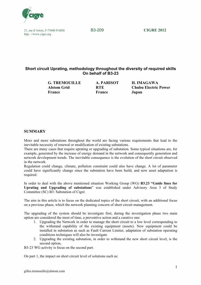
10 Overhead line from 10 to 40 km length 5 substations equipped with bus tie A large generation capability able to deliver a cumulative short circuit of 120 kA r.m.s. divided among
all the substation, through 8 injection points. It mean an equivalent of 16 GW generation. It should keep in mind than in a network not all the generators are connected to the grid in the same time. For maintenance issues, load adjustment some of the generator are stopped and disconnected. This consideration should be keeping in mind when a short circuit study is managed in order to evaluate the short circuit level of a network. Substation have been called: A, B, C, D, E, F
Figure 1: configuration using to show the quantitative impact of short circuit policy and limiting devices The reference short circuit level is calculated with all line connected, all bus tie close and no limiting devises insert on the subnetwork.
1.1 THE IMPACT OF THE NETWORK AND SUBSTATION ARRANGEMENT
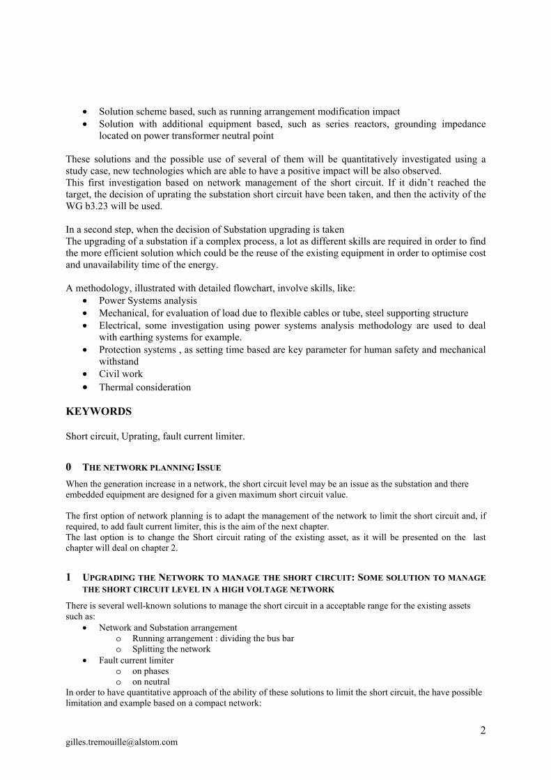
Reducing the network meshing is a policy of network management used at national or regional level to manage the short circuit. The positive impact on short circuit of the coupling bay “ open” such as the “ bus tie open” in signigicant. This solution could be used in the network but should be limited as the network configuration should still able to face one failure. The contingency level N-1 is typically used in HV, UHV network in order to ensure unexpected event (one). An optimal situation is to have not direct connections between sub-network ( see Figure 2 ) ensuring that subnetwork are not meshed together, will limit the contribution coming from lower voltage level to higher voltage level. Having parallel meshed networh
A
B
C
D E
HV transmission
Sub-transmission
Sub-network
Figure 2: different voltage level in a networkFigure 3 : bus tie Close, or Open
1.2 THE FAULT CURRENT LIMITER
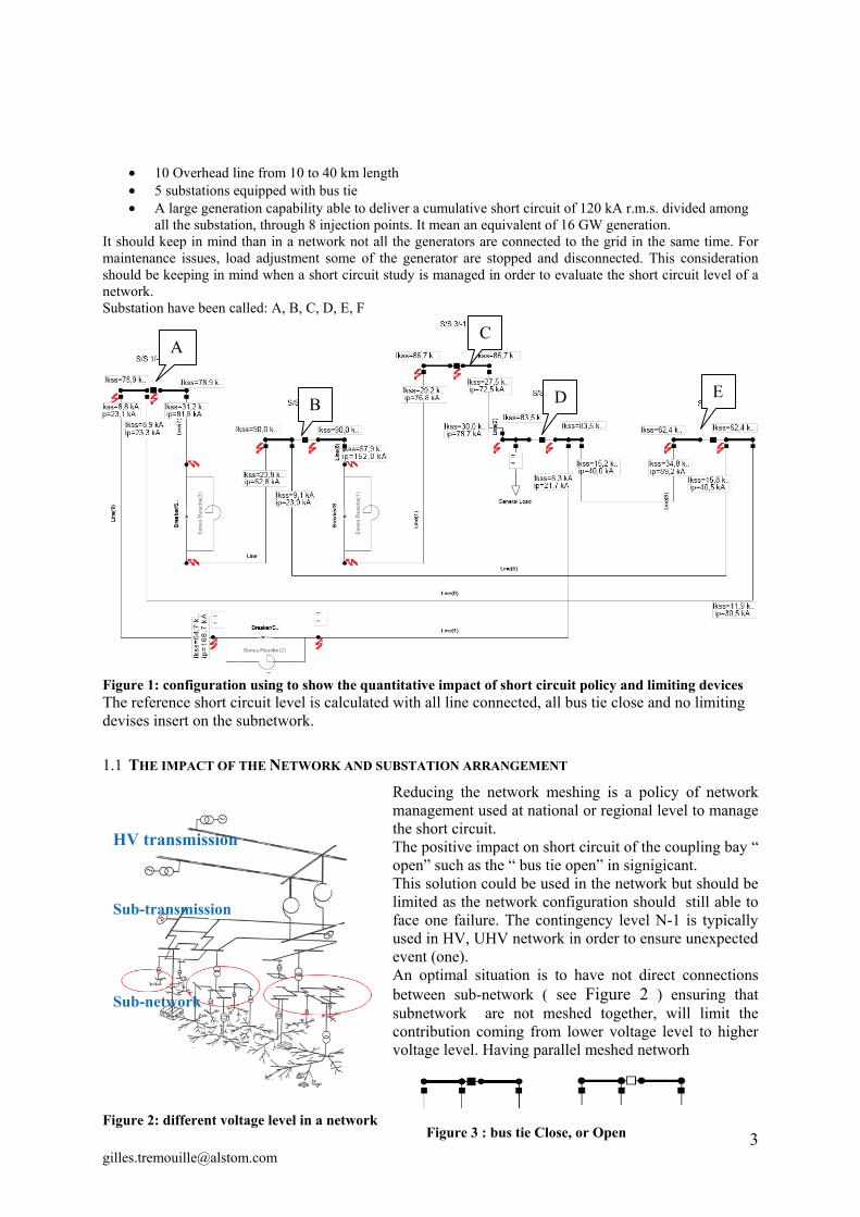
Sereval technology are existing, they are mature such as Series reactor, emerging such as Shielded inductive superconducting. We have propose a summury (Table 1) the existing and mature technology such as series reactance, and also futur technologies.
Fault current limiter devices
Advantage Drawbacks
Series Reactance
Reliability with long experience To check the transient recovery
voltage of the circuit breakers nominal losses
Shielded-Inductive
Superconducting
Self-activating (Laws of Physics) low-maintenance device;
Low voltage drop (enhanced grid stability);
Low nominal losses
Failure of auxiliary cooling system could lead to:
A massive increase of line losses; A reduction of the system stability
margins; Disturbances of system power flow
Normally Off Power Electronic-
Based
Device (current) thresholds straightforward to define leading to an easier-to-integrate device (every grid has specific its needs);
Based on a simple principle using classical passive elements;
Relatively low nominal losses.
Failure of the Power electronic switch could lead to hazardous situations under fault events
Normally On Power Electronic-
Based
Device (current) thresholds straightforward to define leading to an easier-to-integrate device (every grid has specific its needs);
Based on a simple principle using classical passive elements.
Relatively high nominal losses Failure of the Power Electronic switch
would lead to permanent losses and reduced system stability.
Fast-Switches
Extremely rapid response allowing almost instantly reconfiguring the grid;
Almost instantaneous isolation of faulted circuits;
Low nominal losses.
Seems more like a fault current interrupter than an FCL
Only a local impact May require an additional
communication system for opening conventional breakers after operation of the FS and prior to its reclosing.
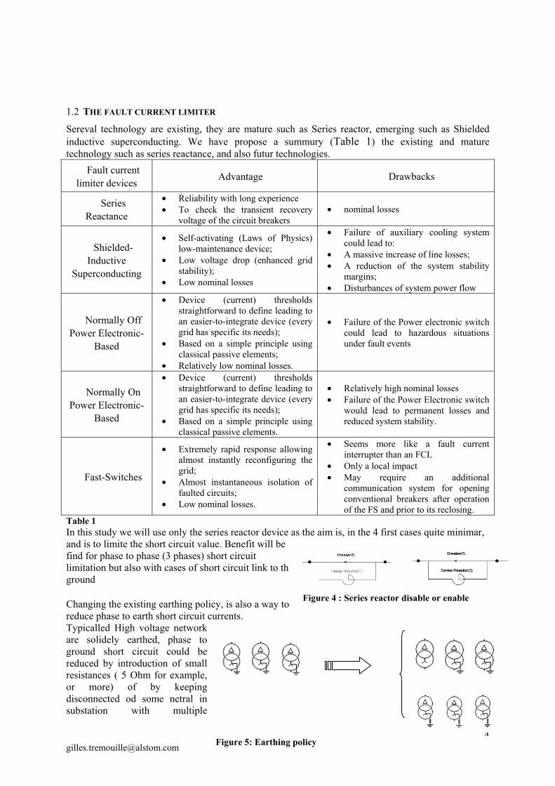
Table 1 In this study we will use only the series reactor device as the aim is, in the 4 first cases quite minimar, and is to limite the short circuit value. Benefit will be find for phase to phase (3 phases) short circuit limitation but also with cases of short circuit link to th ground Changing the existing earthing policy, is also a way to reduce phase to earth short circuit currents. Typicalled High voltage network are solidely earthed, phase to ground short circuit could be reduced by introduction of small resistances ( 5 Ohm for example, or more) of by keeping disconnected od some netral in substation with multiple
Figure 4 : Series reactor disable or enable
Figure 5: Earthing policy
transformer. At lest one neutral should still connected, a N- contingency requirement could reach to maintani at least two transformer neutral connected.
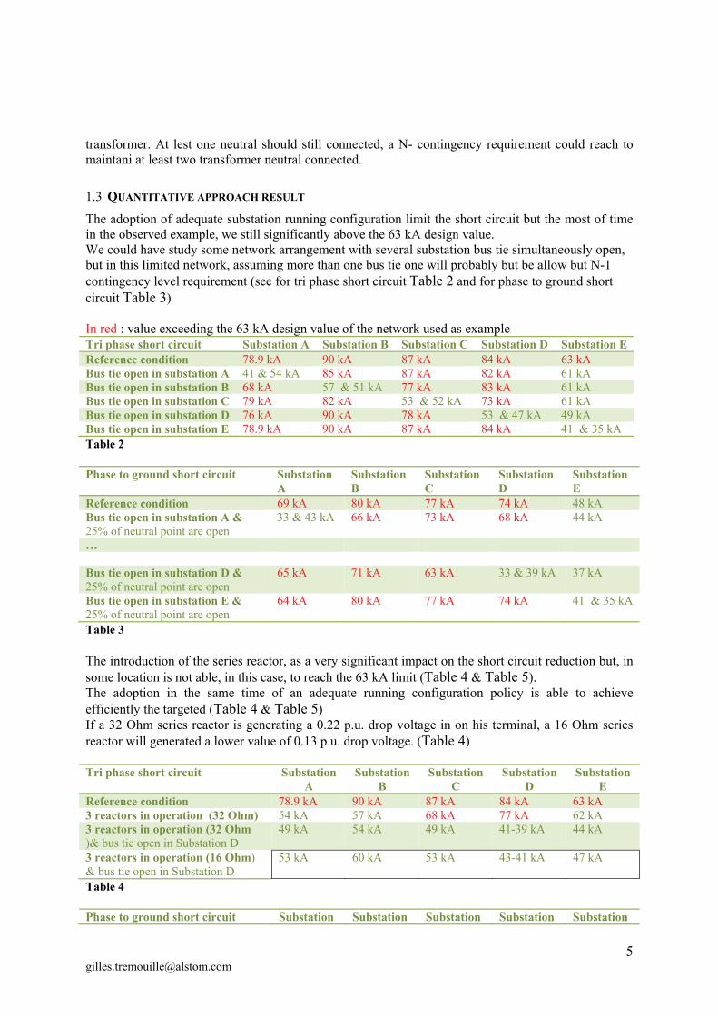
1.3 QUANTITATIVE APPROACH RESULT
The adoption of adequate substation running configuration limit the short circuit but the most of time in the observed example, we still significantly above the 63 kA design value. We could have study some network arrangement with several substation bus tie simultaneously open, but in this limited network, assuming more than one bus tie one will probably but be allow but N-1 contingency level requirement (see for tri phase short circuit Table 2 and for phase to ground short circuit Table 3) In red : value exceeding the 63 kA design value of the network used as example Tri phase short circuit Substation A Substation B Substation C Substation D Substation E Reference condition 78.9 kA 90 kA 87 kA 84 kA 63 kA Bus tie open in substation A 41 & 54 kA 85 kA 87 kA 82 kA 61 kA Bus tie open in substation B 68 kA 57 & 51 kA 77 kA 83 kA 61 kA Bus tie open in substation C 79 kA 82 kA 53 & 52 kA 73 kA 61 kA Bus tie open in substation D 76 kA 90 kA 78 kA 53 & 47 kA 49 kA Bus tie open in substation E 78.9 kA 90 kA 87 kA 84 kA 41 & 35 kA Table 2 Phase to ground short circuit Substation
A Substation B
Substation C
Substation D
Substation E
Reference condition 69 kA 80 kA 77 kA 74 kA 48 kA Bus tie open in substation A & 25% of neutral point are open
33 & 43 kA 66 kA 73 kA 68 kA 44 kA
… Bus tie open in substation D & 25% of neutral point are open
65 kA 71 kA 63 kA 33 & 39 kA 37 kA
Bus tie open in substation E & 25% of neutral point are open
64 kA 80 kA 77 kA 74 kA 41 & 35 kA
Table 3 The introduction of the series reactor, as a very significant impact on the short circuit reduction but, in some location is not able, in this case, to reach the 63 kA limit (Table 4 & Table 5). The adoption in the same time of an adequate running configuration policy is able to achieve efficiently the targeted (Table 4 & Table 5) If a 32 Ohm series reactor is generating a 0.22 p.u. drop voltage in on his terminal, a 16 Ohm series reactor will generated a lower value of 0.13 p.u. drop voltage. (Table 4) Tri phase short circuit Substation
A Substation
B Substation
C Substation
D Substation
E Reference condition 78.9 kA 90 kA 87 kA 84 kA 63 kA 3 reactors in operation (32 Ohm) 54 kA 57 kA 68 kA 77 kA 62 kA 3 reactors in operation (32 Ohm )& bus tie open in Substation D
49 kA 54 kA 49 kA 41-39 kA 44 kA
3 reactors in operation (16 Ohm) & bus tie open in Substation D
53 kA 60 kA 53 kA 43-41 kA 47 kA
Table 4 Phase to ground short circuit Substation Substation Substation Substation Substation
A B C D E Reference condition 69 kA 80 kA 77 kA 74 kA 48 kA Bus tie open in substation A & series reactors inserted (32 Ohm)
30 & 21 kA 53 kA 61 kA 68 kA 46 kA
… Bus tie open in substation D & series reactors inserted ( 32 Ohm)
46 kA 51 kA 48 kA 37 & 34 kA 35 kA
Bus tie open in substation E & series reactors inserted ( 32 Ohm)
45 kA 47 kA 57 kA 56 kA 28 & 22 kA
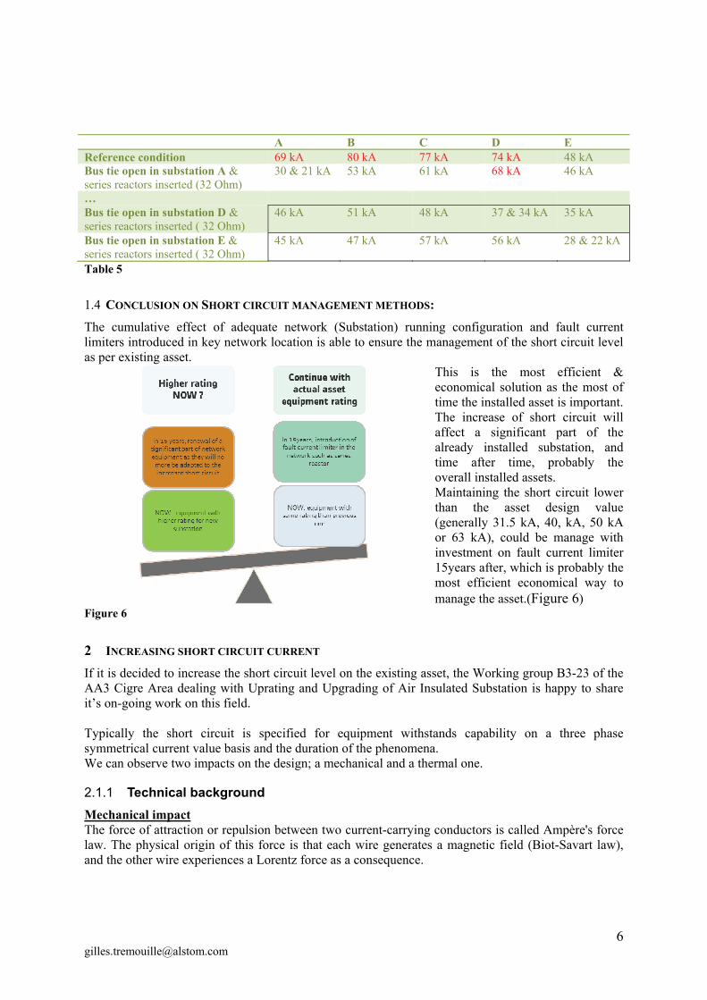
Table 5
1.4 CONCLUSION ON SHORT CIRCUIT MANAGEMENT METHODS:
The cumulative effect of adequate network (Substation) running configuration and fault current limiters introduced in key network location is able to ensure the management of the short circuit level as per existing asset.
This is the most efficient & economical solution as the most of time the installed asset is important. The increase of short circuit will affect a significant part of the already installed substation, and time after time, probably the overall installed assets. Maintaining the short circuit lower than the asset design value (generally 31.5 kA, 40, kA, 50 kA or 63 kA), could be manage with investment on fault current limiter 15years after, which is probably the most efficient economical way to manage the asset.(Figure 6)
Figure 6
2 INCREASING SHORT CIRCUIT CURRENT
If it is decided to increase the short circuit level on the existing asset, the Working group B3-23 of the AA3 Cigre Area dealing with Uprating and Upgrading of Air Insulated Substation is happy to share it’s on-going work on this field. Typically the short circuit is specified for equipment withstands capability on a three phase symmetrical current value basis and the duration of the phenomena. We can observe two impacts on the design; a mechanical and a thermal one.
2.1.1 Technical background
Mechanical impact The force of attraction or repulsion between two current-carrying conductors is called Ampère's force law. The physical origin of this force is that each wire generates a magnetic field (Biot-Savart law), and the other wire experiences a Lorentz force as a consequence.
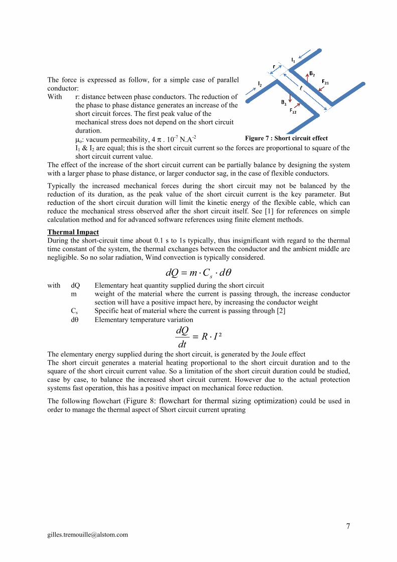
The force is expressed as follow, for a simple case of parallel conductor: With r: distance between phase conductors. The reduction of
the phase to phase distance generates an increase of the short circuit forces. The first peak value of the mechanical stress does not depend on the short circuit duration.
o: vacuum permeability, 4 . 10-7 .A-2 I1 & I2 are equal; this is the short circuit current so the forces are proportional to square of the
short circuit current value. The effect of the increase of the short circuit current can be partially balance by designing the system with a larger phase to phase distance, or larger conductor sag, in the case of flexible conductors.
Typically the increased mechanical forces during the short circuit may not be balanced by the reduction of its duration, as the peak value of the short circuit current is the key parameter. But reduction of the short circuit duration will limit the kinetic energy of the flexible cable, which can reduce the mechanical stress observed after the short circuit itself. See [1] for references on simple calculation method and for advanced software references using finite element methods.
Thermal Impact During the short-circuit time about 0.1 s to 1s typically, thus insignificant with regard to the thermal time constant of the system, the thermal exchanges between the conductor and the ambient middle are negligible. So no solar radiation, Wind convection is typically considered.
dCmdQ s
with dQ Elementary heat quantity supplied during the short circuit m weight of the material where the current is passing through, the increase conductor
section will have a positive impact here, by increasing the conductor weight Cs Specific heat of material where the current is passing through [2] d Elementary temperature variation
²IRdtdQ
The elementary energy supplied during the short circuit, is generated by the Joule effect The short circuit generates a material heating proportional to the short circuit duration and to the square of the short circuit current value. So a limitation of the short circuit duration could be studied, case by case, to balance the increased short circuit current. However due to the actual protection systems fast operation, this has a positive impact on mechanical force reduction.
The following flowchart (Figure 8: flowchart for thermal sizing optimization) could be used in order to manage the thermal aspect of Short circuit current uprating
Figure 7 : Short circuit effect
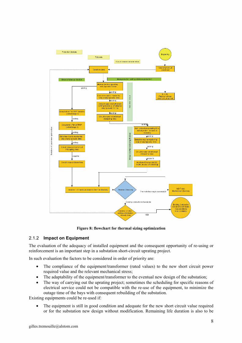
Figure 8: flowchart for thermal sizing optimization
2.1.2 Impact on Equipment
The evaluation of the adequacy of installed equipment and the consequent opportunity of re-using or reinforcement is an important step in a substation short-circuit uprating project.
In such evaluation the factors to be considered in order of priority are:
The compliance of the equipment/transformer (rated values) to the new short circuit power required value and the relevant mechanical stress;
The adaptability of the equipment/transformer to the eventual new design of the substation; The way of carrying out the uprating project; sometimes the scheduling for specific reasons of
electrical service could not be compatible with the re-use of the equipment, to minimize the outage time of the bays with consequent rebuilding of the substation.
Existing equipments could be re-used if:
The equipment is still in good condition and adequate for the new short circuit value required or for the substation new design without modification. Remaining life duration is also to be
considered (i.e. not beyond the threshold of half of its service lifetime). Equipment can be uprated, reaching the new criteria, and/or adapted to the new design criteria
after on-site or in factory modification; in this case a cost - benefit analysis should be done between modification of the existing and the purchase of new equipment, with reference to:
o The expected remaining service life-time of the existing equipment; o The number of equipment, to be modified, because new type-tests should be carried
out on modified equipment by the manufacturer; In general, with reference to the adequacy of the existing equipment, the mechanical load rated values applicable to the terminals must be compared to the dynamic forces evaluated under the new short circuit conditions.
The manufacturer should be asked about the opportunity to do new specific tests to check the withstand capability of the equipments to the new load conditions.
The equipment manufacturer should be involved in the decision making process between the possible uprating and the replacement of the existing equipment.
Circuit breakers: The manufacturer should be asked for existing circuit breakers of the same type with higher short circuit current rated value, and in this case verifying the compliance of the installed circuit breaker design with the new required short circuit level. Disconnectors: The disconnector does not have to open during a short circuit, so the issue of this equipment in case of short circuit is the mechanical withstand of the insulator and the requirement to ensure the contacts remain closed. Furthermore, to avoid formation of hot spots between the contacts of the disconnector no sliding between them during the short circuit is allowed. Substitution of the insulator and contact tightness reinforcement can be fitted in agreement with the manufacturer, who should carry out new type tests of the modified equipment.
Earth switches: For earth switches having short-circuit making current characteristics, this value should be equal to the new value of the rated peak withstand current. Typically, the flexible copper connections between movable parts of an earthing switch and it’s frame shall have a minimum cross section to ensure mechanical strength and resistance to corrosion.
In some cases this flexible connection is used to carry the short circuit current, in this case the flexible connection should be design according to the new short circuit characteristics.
All earth paths shall be rated / modified for the new short circuit currents.
Current transformers: The rated thermal short time current (for thermal concern), the rated dynamic current (for internal mechanical concern) have to be reviewed. The increase of short circuit current in the primary winding of the current transformer would generate a saturation of the magnetic core of the current transformer, which will impact on the accuracy of the value indicated by the current transformer. In any case the compatibility between the current transformers characteristics and the protective devices should be checked to ensure a good protective coordination of the protection system.
The renewal of the protection systems in the same stage will also have a significant impact. The evolution of the protection products has had a positive impact on the compatibility between the current transformer and the relay.
NCIT having a more compact design and less weight than the previous generation could be an interesting alternative for conventional current transformers renewal.
Voltage transformer: Three types of technologies exist inductive, capacitive, or NCIT type. For all technologies rating plate, specification and design are not link with primary short circuit. The short circuit withstand capability test required in standard type test is dealing with a short circuit of the secondary connection (low voltage) of the voltage transformer.
The mechanical withstand capability is defined by standards and link only to the voltage level. In case of reuse of a voltage transformer, the mechanical stress due to the flexible cables or tube connected at the primary terminal should be recalculated keeping under the limit indicated by the standard. Increasing the flexible cable sag, reducing the span, by introduction of additional post insulators, could be investigated to ensure the compliance with this criterion.
NCIT having a more compact design and less weight than the previous generation could be an interesting alternative for conventional instrument transformers renewal.
Surge Arrester: A short circuit withstand capability is most requested, in order to highlight that in case of internal failure, a violent shattering of the arrester housing will not be observed. Open flames should also be self-extinguishing. Therefore an increase of the rated short circuit current of the installation will require replacement of surge arresters with required short circuit withstand capability one.
The surge arrester, which is impacted by aging, is a crucial equipment for the integrity of all other installed equipments
Surge arrester aging could be observed by measurement of the leakage current when the surge arrester is energized.
So the substation uprating is a good opportunity to introduce new surge arrester.
Power transformer: Due to the evolution of transformer standards regarding type test requirements old power transformers may not be adequate. In case of expected reuse, the following investigation should be carried out:
the expected remaining service life time a positive evaluation of the technical condition of the transformer
Explosion-proof performance for internal fault, mechanical strength of windings for passing through short circuit and tertiary winding are key concern.
As return of experience, we can highlight a case coming from Japan [3], where the transformer tank have been reinforced in order to be able to withstand an uprated internal pressure from 50 kA to 63kA – 2s short circuit. Countermeasures based on welding reinforcement have been used, for example to increase from 0.35 MPa, to 0.5 MPa the acceptable tank strength
Such investigations have to be assessed with the transformer manufacturer.
However the costs of such intervention, related to the estimated remaining service lifetime of the existing transformer, must be compared to a new one to make the final decision.
Maintenance equipment: It should be noted that substation maintenance equipment such as removable earthing device should be design for the new short circuit value.
2.1.3 Impact on Structural Components in AIS
The withstand capabilities of existing conductors, supports, gantries, foundations and earthing networks must be checked with the uprated short circuit constraint. It is advisable to evaluate the design margins or possible reinforcement strategies at the basic design stage, due to the generally high cost for reinforcement of structural elements. If costly reinforcements seem necessary, it may be more cost-effective to partially or entirely dismantle the installation and rebuilt with the new constraint.
Some opportunities to use the existing design: Many old substations were designed with empirical formulas or standards and conservative safety factors. As a result, it is generally possible to raise the short circuit current limit of the existing installation by performing more detailed calculations with newer standards, adjusted safety factors and optimized up-to-date parameters. Among the parameters of interest is the operating time of protective devices, which has greatly improved over the last few decades. For line faults detected in zone 1 or busbar faults, the newest relay
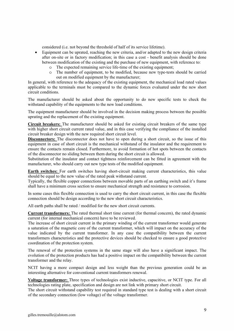
operating time is about 20 to 30ms (or less) and the arc extinction occurs after around 2 to 2,5 cycles , or less. Faults cleared in zone 2 last only some tens of milliseconds more with stage acceleration. These durations are significantly lower than those used when designing substations 20 or 30 years ago.
Figure 9: short circuit duration analysis
Risk assessment techniques can also be considered to maintain existing substations in service for a few years with minimal reinforcement under the new short circuit constraints. Indeed, with modern IT systems and monitoring devices, utilities can obtain extensive statistics on fault characteristics (occurrence, duration, levels, etc) for specific substations, and on other concomitant constraints like wind or icing loads. In light of this data, the overall risk associated with operating the substations above design values for a limited number of years usually proves acceptable when compared with the cost of reinforcement or renewal of the substations. Whether utilities can choose to carry out this risk-based approach depends on local regulations and practices.
Rigid and flexible conductors: Modern finite element software allows accurate calculations of the dynamic mechanical forces developed by short circuits, taking into account the geometry and mechanical characteristics of the substation. The constraints at rated short circuit current are usually found to be much lower than that estimated in the initial design, which provides room for uprating at minimal cost. If some elements are to be reinforced, the simulation provides with the optimal strategy. Hence, the gain in defining the best uprating strategy usually offsets the cost of such advanced numerical studies. An alternative approach for simple rigid and flexible busbar configurations is the simplified calculation method in the. The method is based on CIGRE brochure [4] and its companion guide [1].
Due to its nonlinear characteristic, the mechanical response of flexible conductors under short circuit conditions must be given special attention in the uprating study. A small decrease in cable sag, if
acceptable in terms of electrical clearances, can be effective in reducing the mechanical forces. Addition support could also be introduced in order to reduce the spans.
In bundle conductors, the “pinch” effect can lead to much higher forces on the structures than for a single cable. As a function of the span length between spacers, the effect is a maximum where the cables in the bundle just come into contact during the short circuit. For typical conditions in substations, the critical span length is of order of the 5 to 10 meters. Therefore, additional spacers in closer proximity (less than a meter or so) is usually the best way to reduce the pinch effect forces. In all cases, the stresses on the spacers and connectors must be evaluated.
Insulated cable will also be impacted by phenomena such as:
Mechanical load increase on the conductor clamp Thermal load increase on the conductor
The cable will also be impacted by a current or voltage increase in the insulated cable screen depending on the cable screen earthing principle
The calculated short circuit forces on the conductors can be used to infer stress values on the supporting insulators, structures and gantries.
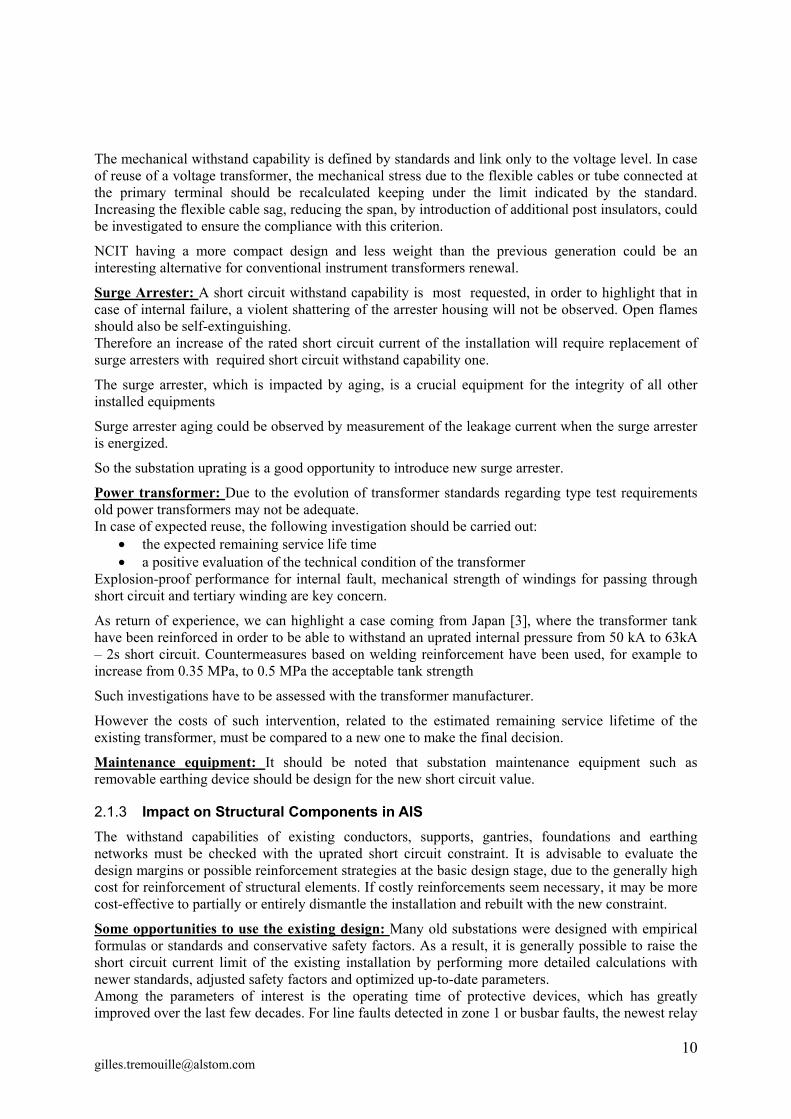
Figure 10: Mechanical load optimization
Insulators Post insulators: If they are not able to withstand the new mechanical stress they must be replaced.
Insulator strings: Due to the relative low span of the flexible connection, the insulator string mechanical withstands capacity is usually not a weak point but should be reviewed.
Anchor strings: Validation or adaptation of horn and shunt should be studied and modified if necessary, in order to reach the new short circuit thermal constraint.
Support, gantries and foundations Verifications of the mechanical stresses in the supports, gantries and underlying foundations must be carried out with the new mechanical short circuit constraints, as per local regulations and company practices.
The studies must yield specific reinforcement strategies when the stress limits are exceeded. In some cases, dismantling and replacing the support and the foundation maybe extended:
When the structure or foundation show signs of ageing or damage When the necessary information to perform the mechanical study is not available (drawings
and mechanical properties), and would be too expensive or impossible to obtain The decision to reinforce or replace steel support, gantries and foundations can impact significantly on the project cost and duration, but due to time constraints the studies to support it may not be available until late in the detailed design stage. Therefore, the high cost scenario (whereby most foundations and structures have to be replaced) should be considered from the project start as a possible risk/outcome, and the uprating strategy should be reviewed in light of the results when they become available. In some cases, it may be more cost-effective to switch to a full “dismantle and rebuild” approach.
Earthing network The earthing connections above and below ground must be able to carry the short circuit currents at the new higher short circuit level. One constraint is the temperature rise in the conductors and surrounding soil; the cross section of the existing conductor has to be checked with the new short circuit value and its duration as fixing devices. If the temperature rise becomes unacceptable, the conductors and its fixings must be replaced.
Since the impact on site activity is important, this limit should be examined at the basic design stage. Note that currents in the buried earthing network are significantly lower than that in connections since the network is well meshed to meet potential rise limits (second constraint below). Hence this constraint concerns mostly the connections.
As mentioned in earlier stage the initial design hypothesis for old substations were usually conservative, with an equivalent short circuit duration of 0,5 to 3 seconds at full short circuit current. As the operating time and reliability of protective relays and circuit breakers has improved, it is usually possible to find significant margins by recalculating the constraint with the current values.
A second constraint is the higher ground potential rise of the substation with the new short circuit level. But the increase of the short circuit is probably also linked with increase of the number of overhead lines and underground cables, so the overall equivalent earth impedance has to be reviewed in this case.
The ground potential rise should stay in acceptable limits in order to manage the possible transferred potential [5,7]. Additional deep rods can be used to reduce the grid resistance and consequently the ground potential rise. Regarding human safety and acceptable “touch and step voltages”, the buried earth grid arrangement should be checked with finite element numerical models, taking into account the operating time of protective devices and circuit breaker operation times. If some switchyard areas have to be modified to ensure these design criteria, additional buried earth grid or additional earth rods can be used. Due to the impact on civil work and erection, this aspect must be examined early in the detailed design stage.
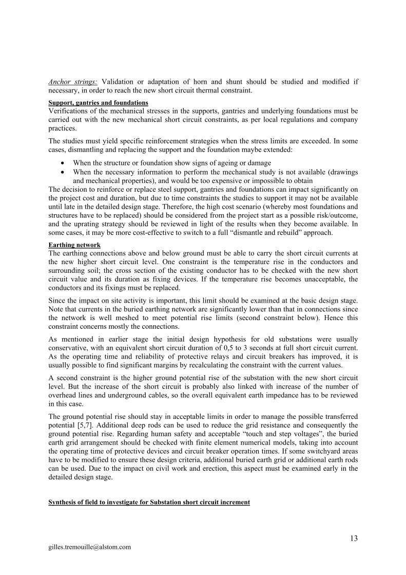
Synthesis of field to investigate for Substation short circuit increment
Basic Design
- Engineering
Equipment modification, manufacturing &
transportation
Site Activities
Civil work, testing , commissioning, Documentation
Mechanical forces on equipment structure and civil work
Clearances Compatibility CT & Protection
Additional structures to limit mechanical forces (possibly)
Equipment to adapt or change
Earthing mat to adapt (possibly) Increased loading on foundation Phasing of site activities in order
to limit outage time Test / explanation evidence of
equipment withstand capability
Figure 11: Chechlist for Short circuit Substation Uprating, main possible issues
3 CONCLUSION
The evolution of the energy demand is obviously impacting the network, is it leading ( on a short circuit point of view) to manage an Uprating of the network configuration or / and an Uprating of the electrical substation.
The point could be addressed with a power system network adaptation using for example fault current limiter devices. In this case the impact on the substation is limited, as the substation short circuit is not modified, thus power systems studies and introduction of new component in the existing substation or in new site location are requested (fault current limited and necessary surrounding equipment and control).
It is also possible to proceed to the Uprating of the overall in order to , the overall substation withstand capability evaluation is necessary and topics like; power systems studies, civil, control systems, protection systems, instrument transformers compatibility, mechanical calculation and thermal. This is the aim of B3.23 “Guide lines for Uprating and Upgrading of substations” was established under Advisory Area 3 of Study Committee (SC) B3: Substation of Cigré.
4 BIBLIOGRAPHY
[1] CIGRE WG23-11, Brochure 105 " The mechanical effects of short-circuit currents in open air substation", 1996.
[2] CIGRE WG23-03, Brochure 214 " the mechanical effects of short circuit currents in open air substations - Part II, a compagnion book for the CIGRE brochure 105", 2002.
[3] L. M. COSTA, Survey of Fault Current Limiter technology - ALSTOM, 2010.
[4] IEC, Standatd 60865-1 " Short circuit currents - calculation of effects", 2011.
[5] IEC, Technical Report 60943 " Guidance concerning the permissible temperature rise for parts of electrical equipment, in particular for terminals, 2009.
5 AUTHORS
Mr. Gilles Trémouille was born in Sens (Bourgogne), France,
on August 12, 1968. He graduated from E.S.T. P (Ecole Speciale des Travaux Public du Batiment et de l'industrie ) Paris, in 1992 as Mechanical Engineering & Power Systems.- Since November 1999,
this school is associated with another, state-owned, French " Grande Ecole ", Ecole Nationale Supérieure d'Arts et Métiers (ENSAM). Gilles start is activity EDF DER (research) in the OHL test center of EDF (Electricité de France). He joint ALSTOM Grid in 1995 (formerly CEGELEC, AREVA T&D). He is a Member of the IEEE. He integrated the Cigre working group C4 (System Technical Performance) & B3
(Substations). Mr. Hiroshi Imagawa was born in Hiroshima, Japan, on
September 29, 1965. He received the Bachelor of Engineering degree in electrical engineering from Osaka University, Japan, in 1988. Since April 1988, he has worked for Chubu Electric Power Company as a substation engineer. He has been participating in CIGRE B3 (Substations) activities
since September 2007, and also serving as a secretary of the Japanese National Committee of CIGRE. He is a Member of IEEJ.