21, rue d’Artois, F-75008 PARIS B3-204 CIGRE 2016 http...
7
[email protected] Countermeasures in a substation for large renewable energy adoption in Japan S.YAMAMOTO Y. MATSUSHITA K. KAWAKITA Tohoku Electric Power Co. Kansai Electric Power Co. Chubu Electric Power Co. K. YAJIMA K. UEHARA T. SHIMOMURA Tokyo Electric Power Co. Toshiba Corp. Mitsubishi Electric Corp. Japan SUMMARY This paper introduces an example of countermeasures taken at substations in Japan in relation to the adoption of a large amount of renewable energy. Since the amount of adoption of renewable energy in Japan is expected to rapidly increase, it is necessary to consider countermeasures for alleviating the influence on power grids. This paper describes, in a time-series order, countermeasures that are being considered for the adoption at substations in Japan. Furthermore, as a specific example, the installation of a large-scale battery (20 MWh) at a transmission substation is illustrated. This equipment was installed at the Nishi-Sendai Substation of Tohoku Electric Power Co. and its operation started in February 2015 in order to demonstrate that it is possible to effectively prevent frequency instability due to renewable energy fluctuation by using a battery. Since there had not been such a case before, this paper introduces the configuration and layout of equipment used in installing a large-scale battery (Capacity: 20 MWh, Output: 40 MW) at a transmission substation. Since the electrolyte in the battery is flammable, it was necessary to consider countermeasures against fire for the safety of the transmission substation. Furthermore, this paper introduces how a large number of PCS (=Power Conditioning System) and battery units (300 V- 500 kW) were connected and configured in the transmission substation in order to connect to the power grid. Furthermore, this paper introduces the basic idea for the control of this large-scale battery, as well as the results of verification. KEYWORDS Renewable Energy - Transmission substation - Battery - Safety measure - Stabilization 21, rue d’Artois, F-75008 PARIS B3-204 CIGRE 2016 http : //www.cigre.org
Transcript of 21, rue d’Artois, F-75008 PARIS B3-204 CIGRE 2016 http...
Countermeasures in a substation for large renewable energy adoption in Japan
S.YAMAMOTO Y. MATSUSHITA K. KAWAKITA
Tohoku Electric Power Co. Kansai Electric Power Co. Chubu Electric Power Co.
K. YAJIMA K. UEHARA T. SHIMOMURA
Tokyo Electric Power Co. Toshiba Corp. Mitsubishi Electric Corp.
Japan
SUMMARY
This paper introduces an example of countermeasures taken at substations in Japan in relation to the
adoption of a large amount of renewable energy. Since the amount of adoption of renewable energy in
Japan is expected to rapidly increase, it is necessary to consider countermeasures for alleviating the
influence on power grids. This paper describes, in a time-series order, countermeasures that are being
considered for the adoption at substations in Japan. Furthermore, as a specific example, the installation
of a large-scale battery (20 MWh) at a transmission substation is illustrated. This equipment was
installed at the Nishi-Sendai Substation of Tohoku Electric Power Co. and its operation started in
February 2015 in order to demonstrate that it is possible to effectively prevent frequency instability
due to renewable energy fluctuation by using a battery. Since there had not been such a case before,
this paper introduces the configuration and layout of equipment used in installing a large-scale battery
(Capacity: 20 MWh, Output: 40 MW) at a transmission substation. Since the electrolyte in the battery
is flammable, it was necessary to consider countermeasures against fire for the safety of the
transmission substation. Furthermore, this paper introduces how a large number of PCS (=Power
Conditioning System) and battery units (300 V- 500 kW) were connected and configured in the
transmission substation in order to connect to the power grid. Furthermore, this paper introduces the
basic idea for the control of this large-scale battery, as well as the results of verification.
KEYWORDS
Renewable Energy - Transmission substation - Battery - Safety measure - Stabilization
21, rue d’Artois, F-75008 PARIS B3-204 CIGRE 2016 http : //www.cigre.org
1
1. INTRODUCTION
With the rapidly increasing adoption of renewable energy worldwide, the expansion of power
transmission and distribution grids and the effective utilization of this unstable power source have
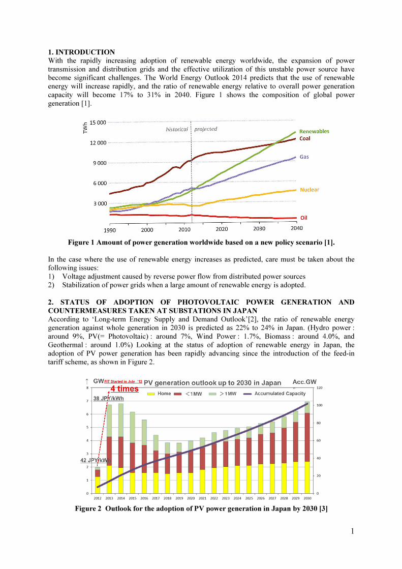
become significant challenges. The World Energy Outlook 2014 predicts that the use of renewable
energy will increase rapidly, and the ratio of renewable energy relative to overall power generation
capacity will become 17% to 31% in 2040. Figure 1 shows the composition of global power
generation [1].
Figure 1 Amount of power generation worldwide based on a new policy scenario [1].
In the case where the use of renewable energy increases as predicted, care must be taken about the
following issues:
1) Voltage adjustment caused by reverse power flow from distributed power sources
2) Stabilization of power grids when a large amount of renewable energy is adopted.
2. STATUS OF ADOPTION OF PHOTOVOLTAIC POWER GENERATION AND
COUNTERMEASURES TAKEN AT SUBSTATIONS IN JAPAN
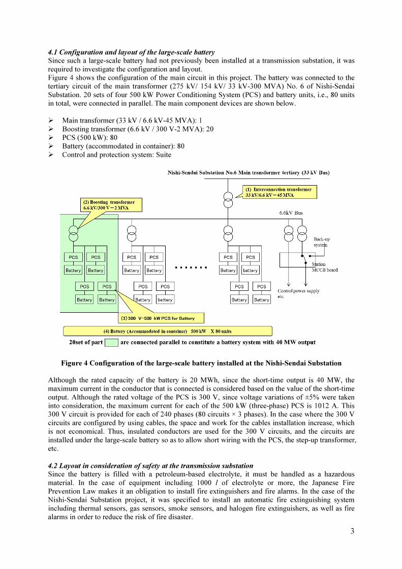
According to ‘Long-term Energy Supply and Demand Outlook’[2], the ratio of renewable energy
generation against whole generation in 2030 is predicted as 22% to 24% in Japan. (Hydro power :
around 9%, PV(= Photovoltaic) : around 7%, Wind Power : 1.7%, Biomass : around 4.0%, and
Geothermal : around 1.0%) Looking at the status of adoption of renewable energy in Japan, the
adoption of PV power generation has been rapidly advancing since the introduction of the feed-in
tariff scheme, as shown in Figure 2.
Figure 2 Outlook for the adoption of PV power generation in Japan by 2030 [3]

2
For the past few years, PV power generation has been adopted at a rate of 7 GW/year. Thus,
countermeasures against reverse power flows from distributed power sources such as PV power
generation are being taken at distribution substations, and a large-scale batteries are being installed at
transmission substations.
3. COUNTERMEASURES AT SUBSTATIONS IN RELATION TO THR INCREASING USE
OF RENEWABLE ENERGY IN JAPAN
As a result of investigation with the power grids in Japan, it was reported that extra power occurred
when the amount of actual power generation using renewable energy exceeded 10 GW, a battery for
accumulating extra power became necessary when the amount of actual power generation using
renewable energy further exceeded 13 GW, and it was necessary to carry out the development and
demonstration of cooperative control among PV power generation, power storage battery, thermal
power generation, and hydroelectric power generation in order to achieve 28 GW, the target value of
the adoption of PV power generation for around 2020 [4].
In Japan, the following countermeasures at substations are being considered in relation to the
increasing use of renewable energy.
Step 1: Initial increase in the use of renewable energy → Countermeasures against reverse power
flows and measures for voltage adjustment at distribution substations (2010 to 2020)
Step 2: Installation of large-scale batteries at transmission substations and development and
demonstration of cooperative control among large-scale batteries and thermal and hydroelectric power
generation → Verification in real projects (2015 to 2018)
Step 3: Increase in the use of renewable energy (PV-installation capacity of about 28 GW) → Practical
application of large-scale batteries at transmission substations (from around 2020)
4. LARGE-SCALE BATTERY INSTALLED AT TRANSMISSION SUBSTATION
In February 2015, the operation of the world's largest battery started at the Nishi-Sendai Substation of
Tohoku Electric Power Co. in Japan. Figure 3 shows an overview and picture of the battery. This
equipment was installed in order to verify that, by using a large-scale battery, it is possible to
effectively suppress the instability in the power supply frequency due to variations in renewable
energy. It is one of the large-scale battery demonstration projects of the Ministry of Economy, Trade
and Industry in the fiscal year 2012. The equipment serves for verification of the effectiveness of large
batteries in the future where a large amount of renewable energy is adopted.
• Output: 40,000 kW
• Capacity 20,000 kWh
• Installation area: About 6,000 m2 (60 m × 100 m) in Substation area 180,000 m
2
• Type: Lithium-ion secondary battery
Figure 3 Large-scale battery installed at Nishi-Sendai Substation
(Operation started in February 2015)
PCS and
transformer
Monitor & control
equipment
Battery (installed in container) Battery (installed in container)
Interconnection
equipment
3
4.1 Configuration and layout of the large-scale battery
Since such a large-scale battery had not previously been installed at a transmission substation, it was
required to investigate the configuration and layout.
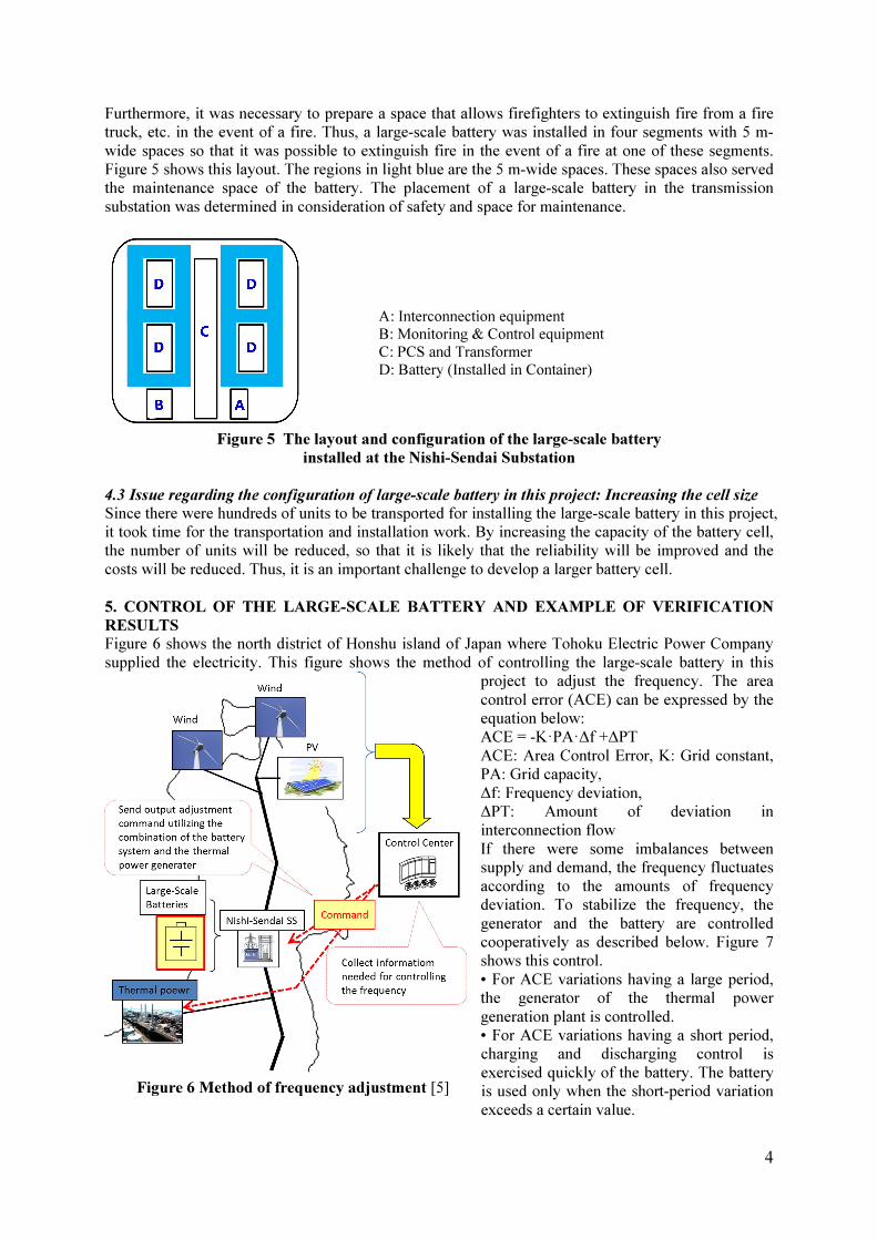
Figure 4 shows the configuration of the main circuit in this project. The battery was connected to the
tertiary circuit of the main transformer (275 kV/ 154 kV/ 33 kV-300 MVA) No. 6 of Nishi-Sendai
Substation. 20 sets of four 500 kW Power Conditioning System (PCS) and battery units, i.e., 80 units
in total, were connected in parallel. The main component devices are shown below.
� Main transformer (33 kV / 6.6 kV-45 MVA): 1
� Boosting transformer (6.6 kV / 300 V-2 MVA): 20
� PCS (500 kW): 80
� Battery (accommodated in container): 80
� Control and protection system: Suite
Figure 4 Configuration of the large-scale battery installed at the Nishi-Sendai Substation
Although the rated capacity of the battery is 20 MWh, since the short-time output is 40 MW, the
maximum current in the conductor that is connected is considered based on the value of the short-time
output. Although the rated voltage of the PCS is 300 V, since voltage variations of ±5% were taken
into consideration, the maximum current for each of the 500 kW (three-phase) PCS is 1012 A. This
300 V circuit is provided for each of 240 phases (80 circuits × 3 phases). In the case where the 300 V
circuits are configured by using cables, the space and work for the cables installation increase, which
is not economical. Thus, insulated conductors are used for the 300 V circuits, and the circuits are
installed under the large-scale battery so as to allow short wiring with the PCS, the step-up transformer,
etc.
4.2 Layout in consideration of safety at the transmission substation
Since the battery is filled with a petroleum-based electrolyte, it must be handled as a hazardous
material. In the case of equipment including 1000 l of electrolyte or more, the Japanese Fire
Prevention Law makes it an obligation to install fire extinguishers and fire alarms. In the case of the
Nishi-Sendai Substation project, it was specified to install an automatic fire extinguishing system
including thermal sensors, gas sensors, smoke sensors, and halogen fire extinguishers, as well as fire
alarms in order to reduce the risk of fire disaster.
4
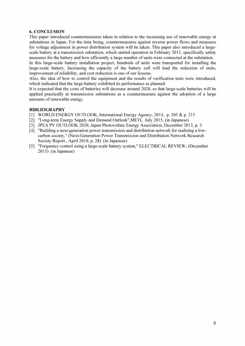
Furthermore, it was necessary to prepare a space that allows firefighters to extinguish fire from a fire
truck, etc. in the event of a fire. Thus, a large-scale battery was installed in four segments with 5 m-
wide spaces so that it was possible to extinguish fire in the event of a fire at one of these segments.
Figure 5 shows this layout. The regions in light blue are the 5 m-wide spaces. These spaces also served
the maintenance space of the battery. The placement of a large-scale battery in the transmission
substation was determined in consideration of safety and space for maintenance.
Figure 5 The layout and configuration of the large-scale battery
installed at the Nishi-Sendai Substation
4.3 Issue regarding the configuration of large-scale battery in this project: Increasing the cell size
Since there were hundreds of units to be transported for installing the large-scale battery in this project,
it took time for the transportation and installation work. By increasing the capacity of the battery cell,
the number of units will be reduced, so that it is likely that the reliability will be improved and the
costs will be reduced. Thus, it is an important challenge to develop a larger battery cell.
5. CONTROL OF THE LARGE-SCALE BATTERY AND EXAMPLE OF VERIFICATION
RESULTS
Figure 6 shows the north district of Honshu island of Japan where Tohoku Electric Power Company
supplied the electricity. This figure shows the method of controlling the large-scale battery in this
project to adjust the frequency. The area
control error (ACE) can be expressed by the
equation below:
ACE = -K·PA·∆f +∆PT
ACE: Area Control Error, K: Grid constant,
PA: Grid capacity,
∆f: Frequency deviation,
∆PT: Amount of deviation in
interconnection flow
If there were some imbalances between
supply and demand, the frequency fluctuates
according to the amounts of frequency
deviation. To stabilize the frequency, the
generator and the battery are controlled
cooperatively as described below. Figure 7
shows this control.
• For ACE variations having a large period,
the generator of the thermal power
generation plant is controlled.
• For ACE variations having a short period, charging and discharging control is
exercised quickly of the battery. The battery
is used only when the short-period variation
exceeds a certain value.
A: Interconnection equipment
B: Monitoring & Control equipment
C: PCS and Transformer
D: Battery (Installed in Container)
Figure 6 Method of frequency adjustment [5]

5
By reducing charging and discharging of the battery, it is possible to suppress a temperature rise,
which allows the battery capacity to be reduced.
Figure 7 Cooperative control based on frequency components of demand variations [5]
Figure 8 shows an example of the results demonstrated with the grid. The purpose of this verification
test is to confirm the performance of cooperative control of the generator and battery to control the
frequency deviation due to fluctuation of wind power and PV power. The control method considers the
suppressing the influence to the life expectancy of the large-scale battery. Figure 8 shows the
cooperative control operates well to control the frequency. But detail control settings are now verified
and the best settings will be established.
Data at 10:00-16:00 on March 10, 2015
Figure 8 ACE-based commands for charging and discharging the battery
and the charging level of the battery [5]
6
6. CONCLUSION
This paper introduced countermeasures taken in relation to the increasing use of renewable energy at
substations in Japan. For the time being, countermeasures against reverse power flows and measures
for voltage adjustment in power distribution system will be taken. This paper also introduced a large-
scale battery at a transmission substation, which started operation in February 2015, specifically safety
measures for the battery and how efficiently a large number of units were connected at the substation.
In this large-scale battery installation project, hundreds of units were transported for installing the
large-scale battery. Increasing the capacity of the battery cell will lead the reduction of units,
improvement of reliability, and cost reduction is one of our lessons.
Also, the idea of how to control the equipment and the results of verification tests were introduced,
which indicated that the large-battery exhibited its performance as planned.
It is expected that the costs of batteries will decrease around 2020, so that large-scale batteries will be
applied practically at transmission substations as a countermeasure against the adoption of a large
amounts of renewable energy.
BIBLIOGRAPHY
[1] WORLD ENERGY OUTLOOK, International Energy Agency, 2014, p. 205 & p. 215
[2] "Long-term Energy Supply and Demand Outlook",METI, July 2015, (in Japanese)
[3] JPEA PV OUTLOOK 2030, Japan Photovoltaic Energy Association, December 2013, p. 3
[4] "Building a next-generation power transmission and distribution network for realizing a low-
carbon society," (Next-Generation Power Transmission and Distribution Network Research
Society Report , April 2010, p. 28) (in Japanese)
[5] "Frequency control using a large-scale battery system," ELECTRICAL REVIEW, (December
2015) (in Japanese)