2.1 Introduction 2.2 Proposed Action Componentscms.cityoftacoma.org/planning/pse/PSE DEIS Chapter...
43
2 Description of Proposed Action 2.1 Introduction Puget Sound Energy (PSE) is the proponent of the Proposed Action, which consists of the construction, operation, and decommissioning of the Tacoma Liquefied Natural Gas (LNG) Project (Project). PSE is a corporation organized under the laws of the State of Washington. The company is a Washington-regulated utility serving 1.1 million electric customers and over 800,000 natural gas customers in 11 counties across the state. This chapter describes the Proposed Action, including the components, construction procedures, and operations of the Proposed Action. 2.2 Proposed Action Components The proposed Project would consist of three main components: (1) Tacoma LNG Facility, (2) Totem Ocean Trailer Express (TOTE) Marine Vessel LNG Fueling System, and (3) associated improvements to the existing PSE Natural Gas Distribution System. All components are subject to numerous applicable regulations. The main components of the Project are described below. 2.2.1 Tacoma LNG Facility 2.2.1.1 Overview The Tacoma LNG Facility would produce between 250,000 to 500,000 gallons of LNG per day. This LNG volume is less than typical LNG import-export facilities that serve world markets. The LNG would be distributed to marine customers, including TOTE, who would use the LNG as a cleaner-burning vessel fuel, as well as re-gasifying the LNG for reinjection into the PSE natural gas distribution system for peak-shaving purposes. An additional use would be providing LNG to other industries or merchants, such as fuel for high- horsepower trucks used in long-haul trucking. The LNG would be stored in the Tacoma LNG Facility LNG storage tank before being transferred to TOTE’s ships via either cryogenic pipeline as part of the TOTE Marine Vessel LNG Fueling System or bunkering barge originating at the Hylebos Waterway pier. Other industry merchants could transport LNG from the Tacoma LNG Facility by tanker trucks or, most likely, by barge that could be filled at either the TOTE Marine Vessel LNG Fueling System or the Hylebos pier. The Tacoma LNG Facility would operate and be staffed with approximately 16 to 18 full-time employees 24 hours per day, 365 days a year. PSE staff would also be responsible for operating and maintaining the LNG pipeline and fuel loading equipment that would be located on TOTE’s property. Maintenance and operating protocols would be developed taking into account federal and state regulations, PSE policies and practices, and best industry practices. Additionally, PSE would contract for security service as required to meet regulatory requirements and for stevedoring services to bunker TOTE’s ships and load other marine vessels. LNG Properties LNG is natural gas in its liquid state. To reach the liquid state, natural gas is cooled to -260 degrees Fahrenheit (°F). Similar to natural gas in its vapor state, LNG is odorless, colorless, non-corrosive, and nontoxic. LNG has a density of approximately 26.5 pounds per cubic foot and is neither flammable nor explosive. Upon conversion to its liquid form, natural gas condenses to occupy a volume that is 1/600 the original volume in its gaseous form. In its liquid form, natural gas is stored at or near atmospheric pressure. LNG vaporizes rapidly on contact with a temperature warmer than the LNG itself. At -259°F, LNG becomes a dense vapor. Between -259°F and -160°F, the LNG vapor is heavier than air and pools at the ground level in collection pools or sumps. Vapor captured in the sumps continues to warm, and, at -160°F, the LNG vapor becomes buoyant, rises, and rapidly disperses into the atmosphere. 2-1
Transcript of 2.1 Introduction 2.2 Proposed Action Componentscms.cityoftacoma.org/planning/pse/PSE DEIS Chapter...
2 Description of Proposed Action 2.1 Introduction Puget Sound Energy (PSE) is the proponent of the Proposed Action, which consists of the construction, operation, and decommissioning of the Tacoma Liquefied Natural Gas (LNG) Project (Project). PSE is a corporation organized under the laws of the State of Washington. The company is a Washington-regulated utility serving 1.1 million electric customers and over 800,000 natural gas customers in 11 counties across the state. This chapter describes the Proposed Action, including the components, construction procedures, and operations of the Proposed Action.
2.2 Proposed Action Components The proposed Project would consist of three main components: (1) Tacoma LNG Facility, (2) Totem Ocean Trailer Express (TOTE) Marine Vessel LNG Fueling System, and (3) associated improvements to the existing PSE Natural Gas Distribution System. All components are subject to numerous applicable regulations. The main components of the Project are described below.
2.2.1 Tacoma LNG Facility 2.2.1.1 Overview The Tacoma LNG Facility would produce between 250,000 to 500,000 gallons of LNG per day. This LNG volume is less than typical LNG import-export facilities that serve world markets. The LNG would be distributed to marine customers, including TOTE, who would use the LNG as a cleaner-burning vessel fuel, as well as re-gasifying the LNG for reinjection into the PSE natural gas distribution system for peak-shaving purposes. An additional use would be providing LNG to other industries or merchants, such as fuel for high-horsepower trucks used in long-haul trucking.
The LNG would be stored in the Tacoma LNG Facility LNG storage tank before being transferred to TOTE’s ships via either cryogenic pipeline as part of the TOTE Marine Vessel LNG Fueling System or bunkering barge originating at the Hylebos Waterway pier.
Other industry merchants could transport LNG from the Tacoma LNG Facility by tanker trucks or, most likely, by barge that could be filled at either the TOTE Marine Vessel LNG Fueling System or the Hylebos pier.
The Tacoma LNG Facility would operate and be staffed with approximately 16 to 18 full-time employees 24 hours per day, 365 days a year. PSE staff would also be responsible for operating and maintaining the LNG pipeline and fuel loading equipment that would be located on TOTE’s property. Maintenance and operating protocols would be developed taking into account federal and state regulations, PSE policies and practices, and best industry practices. Additionally, PSE would contract for security service as required to meet regulatory requirements and for stevedoring services to bunker TOTE’s ships and load other marine vessels.
LNG Properties LNG is natural gas in its liquid state. To reach the liquid state, natural gas is cooled to -260 degrees Fahrenheit (°F). Similar to natural gas in its vapor state, LNG is odorless, colorless, non-corrosive, and nontoxic. LNG has a density of approximately 26.5 pounds per cubic foot and is neither flammable nor explosive. Upon conversion to its liquid form, natural gas condenses to occupy a volume that is 1/600 the original volume in its gaseous form. In its liquid form, natural gas is stored at or near atmospheric pressure.
LNG vaporizes rapidly on contact with a temperature warmer than the LNG itself. At -259°F, LNG becomes a dense vapor. Between -259°F and -160°F, the LNG vapor is heavier than air and pools at the ground level in collection pools or sumps. Vapor captured in the sumps continues to warm, and, at -160°F, the LNG vapor becomes buoyant, rises, and rapidly disperses into the atmosphere.
2-1
PUGET SOUND ENERGY PROPOSED TACOMA LNG FACILITY DRAFT ENVIRONMENTAL IMPACT STATEMENT
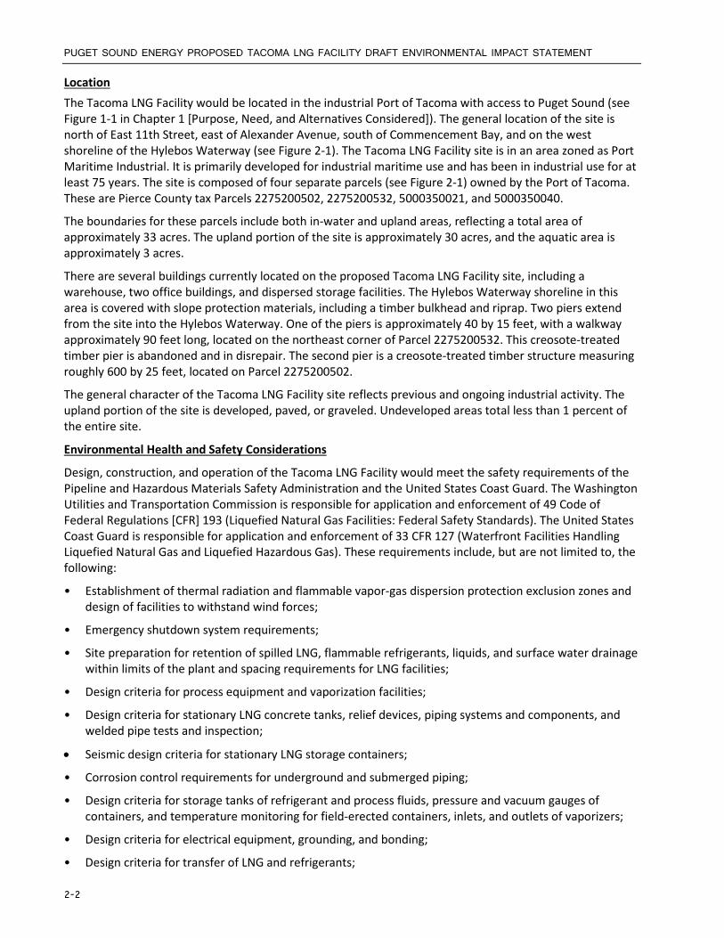
Location The Tacoma LNG Facility would be located in the industrial Port of Tacoma with access to Puget Sound (see Figure 1-1 in Chapter 1 [Purpose, Need, and Alternatives Considered]). The general location of the site is north of East 11th Street, east of Alexander Avenue, south of Commencement Bay, and on the west shoreline of the Hylebos Waterway (see Figure 2-1). The Tacoma LNG Facility site is in an area zoned as Port Maritime Industrial. It is primarily developed for industrial maritime use and has been in industrial use for at least 75 years. The site is composed of four separate parcels (see Figure 2-1) owned by the Port of Tacoma. These are Pierce County tax Parcels 2275200502, 2275200532, 5000350021, and 5000350040.
The boundaries for these parcels include both in-water and upland areas, reflecting a total area of approximately 33 acres. The upland portion of the site is approximately 30 acres, and the aquatic area is approximately 3 acres.
There are several buildings currently located on the proposed Tacoma LNG Facility site, including a warehouse, two office buildings, and dispersed storage facilities. The Hylebos Waterway shoreline in this area is covered with slope protection materials, including a timber bulkhead and riprap. Two piers extend from the site into the Hylebos Waterway. One of the piers is approximately 40 by 15 feet, with a walkway approximately 90 feet long, located on the northeast corner of Parcel 2275200532. This creosote-treated timber pier is abandoned and in disrepair. The second pier is a creosote-treated timber structure measuring roughly 600 by 25 feet, located on Parcel 2275200502.
The general character of the Tacoma LNG Facility site reflects previous and ongoing industrial activity. The upland portion of the site is developed, paved, or graveled. Undeveloped areas total less than 1 percent of the entire site.
Environmental Health and Safety Considerations
Design, construction, and operation of the Tacoma LNG Facility would meet the safety requirements of the Pipeline and Hazardous Materials Safety Administration and the United States Coast Guard. The Washington Utilities and Transportation Commission is responsible for application and enforcement of 49 Code of Federal Regulations [CFR] 193 (Liquefied Natural Gas Facilities: Federal Safety Standards). The United States Coast Guard is responsible for application and enforcement of 33 CFR 127 (Waterfront Facilities Handling Liquefied Natural Gas and Liquefied Hazardous Gas). These requirements include, but are not limited to, the following:
• Establishment of thermal radiation and flammable vapor-gas dispersion protection exclusion zones and design of facilities to withstand wind forces;
• Emergency shutdown system requirements;
• Site preparation for retention of spilled LNG, flammable refrigerants, liquids, and surface water drainage within limits of the plant and spacing requirements for LNG facilities;
• Design criteria for process equipment and vaporization facilities;
• Design criteria for stationary LNG concrete tanks, relief devices, piping systems and components, and welded pipe tests and inspection;
• Seismic design criteria for stationary LNG storage containers;
• Corrosion control requirements for underground and submerged piping;
• Design criteria for storage tanks of refrigerant and process fluids, pressure and vacuum gauges of containers, and temperature monitoring for field-erected containers, inlets, and outlets of vaporizers;
• Design criteria for electrical equipment, grounding, and bonding;
• Design criteria for transfer of LNG and refrigerants;
2-2

CHAPTER 2: DESCRIPTION OF PROPOSED ACTION
• Fire protection provisions; and
• Personnel qualifications and training.
Key Components The Project would include a variety of components further described in this section. All components of the Project are included in an Integrated Safety and Control System. The proposed site plan is shown in Figure 2-2. Additional details about the layout of the various components proposed at the Tacoma LNG Facility are shown in Figure 2-3.
2.2.1.2 Natural Gas Delivery and Pretreatment Systems Natural gas would be delivered by a distribution pipeline and metered before it enters the Tacoma LNG Facility. Natural gas, upon delivery and prior to conversion to LNG, must be conditioned. This entails the removal of any constituents other than pure methane. These constituents could include ethane, propane, butane, and other heavy-end hydrocarbons, as well as minor quantities of nitrogen, carbon dioxide, sulfur compounds, and water. The pretreatment system would consist of amine gas treating and regeneration, a gas dehydration system, outlet gas filtration, and an intermediate heat transfer fluid system.
As part of the pretreatment process, carbon dioxide and sulfur compounds removed from the natural gas would be flared through a ground flare system described in Section 2.2.1.7 (Other Process Facilities). Heavy hydrocarbons are used as fuel gas to the maximum extent possible, also described in Section 2.2.1.7. When operating conditions are such that all of the heavy hydrocarbons are not used as fuel gas, the components are sent to a holding tank. Periodically, this holding tank would be emptied and its contents transferred to a truck and taken off site for disposal or sale to a third party for use as fuel.
2.2.1.3 Liquefaction LNG would be produced using a mixed refrigerant design process. This closed loop system uses a specific, but adjustable, mixture of methane, ethylene, propane, isopentane, and nitrogen as refrigerant. These constituents would be stored on site. The refrigerant would pass through heat exchangers to cool the gas to a liquid (cryogenic) temperature. Refrigerant storage tank would be underground with the following capacities:
• Propane Storage Vessel - 4,500 gallons • Isopentane Storage Vessel - 4,500 gallons • Ethylene Storage Vessel - 4,500 gallons
2.2.1.4 LNG Storage A single LNG storage tank (see Figure 2-4) would be constructed on site to store LNG at cryogenic temperatures with a working capacity of 8 million gallons. The temperature of the LNG must be consistent in order for it to remain in its liquid state. LNG is a boiling cryogen, meaning that it is a very cold liquid at the pressure it is being stored. The LNG vapor released by the boiling liquid helps to maintain the temperature of the LNG within the storage tank. Even with increased heat, the temperature of the fluid itself does not change because it is cooled by evaporation, or the creation of vapor. These vapors are collected, placed back into the liquefaction processor, and sent back to the tank. The LNG storage tank would be a full containment structure consisting of a steel inner tank and a prestressed concrete outer tank. An aluminum suspended deck would sit atop the LNG surface in the inner tank. The storage tank would rest upon a seismic stabilization system. Insulation materials would be installed between the inner and outer tanks to minimize heat gain from the atmosphere to the inner tank contents. The tank would be approximately 130 feet in diameter and 140 feet in height.
Every element in the inner tank would be composed of material that can perform at a temperature of -270°F. This includes internal piping systems. All storage tank piping connections would be located at the top
2-3

PUGET SOUND ENERGY PROPOSED TACOMA LNG FACILITY DRAFT ENVIRONMENTAL IMPACT STATEMENT
of the tank to avoid any structural penetrations through either the sidewall or bottom of both the inner and outer tanks, thereby mitigating the potential for leaks.
The tank would have redundant pumps of sufficient capacity to pump LNG at design loading rates. Instrumentation and safety systems would be included for proper long-term safe operation and control.
2.2.1.5 LNG Vaporization for Peak Shaving The LNG vaporization system would consist of a pump and vaporizer. The vaporization pump would be external to the LNG storage tank and would boost the pressure to a sufficient level for vaporization and reinjection into the PSE Natural Gas Distribution System pipeline. The vaporizer would consist of a warm water bath that heats the LNG to a gaseous state suitable for use in the pipeline. The vaporization system would have the capacity to deliver 66 million standard cubic feet per day of natural gas at the standard distribution pipeline pressure. The gas sent out to the natural gas pipeline would be metered and odorized. Only one pipeline would convey natural gas to and from the Tacoma LNG Facility. Thus, when the vaporization and reinjection system is operating, the LNG liquefaction system would be shut down.
2.2.1.6 LNG Transfer Facilities The Tacoma LNG Facility would have three ways to deliver LNG for use as fuel. The facility would include infrastructure for: (1) loading bunkering barges at the Hylebos Waterway pier for fueling marine vessels, (2) conveying LNG by underground pipeline to the TOTE Marine Vessel LNG Fueling System to directly fuel TOTE ships in the Blair Waterway, and (3) loading tanker trucks for further distribution.
Hylebos Pier To accommodate LNG bunkering operations at the Project site, a new concrete pier would replace an existing timber pier in the Hylebos Waterway, as shown in Figures 2-5 and 2-6. The proposed location for the new pier is shown in Figure 2-2. Preliminary details of the pier are shown in Figures 2-7 through 2-10. Information about the piles that would be used to construct the new pier and associated dolphins is summarized in Table 2-1 and discussed below.
Table 2-1 Tacoma LNG Facility Pier and Dolphin Piles Component Number Construction Material and Dimensions
Trestle and loading Platform 26 30-inch-diameter steel pipe piles
Fender system 16a 18-inch-diameter steel pipe piles
Breasting dolphins 40b 18-inch-diameter steel pipe piles
Catwalks 4 18-inch-diameter steel pipe piles
Bulkhead 1 600-foot-long steel sheet pile
Total 86c Steel pipe piles; dimensions various aTwo groups of four on the platform, four on each of two breasting dolphins. bFour dolphins, each consisting of 10 piles (not including fender piles). cDoes not include the steel sheet pile.
The new concrete pier would have less surface area than the wood pier to be removed. The concrete pier is proposed to be 60 feet long by 25 feet wide (1,500 square feet [ft2]) and would include a 68-foot-long by 33-foot-wide (2,244 ft2) concrete access trestle extending from the upland portion of the site. In addition to a 20-foot-wide access lane for fire vehicles, the access trestle would have an 8-foot-wide combination spill channel and pipe support area. The pier and access trestle would be constructed of precast concrete panels or poured-in-place concrete that meets the requirements of 49 CFR Part 193 (Liquefied Natural Gas
2-4

CHAPTER 2: DESCRIPTION OF PROPOSED ACTION
Facilities) and National Fire Protection Association Standard 59A (Standard for the Production, Storage, and Handling of Liquefied Natural Gas; NFPA 2013).
The new pier and trestle would be constructed with 26 steel pipe piles 30 inches in diameter. The fender system at the face of the pier would consist of two groups of four 18-inch-diameter steel pipe piles with an ultra-high molecular weight polyethylene rub strip on the breasting face of each fender pile. Rubber fender elements would help absorb berthing energy from docking vessels.
The berthing system would also include four 15- by 15-foot (225 ft2 each) dolphins, positioned at either end of the pier. The dolphins would each be supported by up to 10 steel pipe piles 18 inches in diameter. The two inner dolphins would be used for both breasting and mooring and would each have four 18-inch-diameter steel pipe fender piles with an ultra-high molecular weight polyethylene rub strip on the breasting face of each fender pile. The outer dolphins would be for mooring only and would not have fenders. Access to the dolphins would be provided by aluminum or steel-grated catwalks with a total surface area of 1,450 ft2.
Shoreline Improvement The existing shoreline along the Hylebos Waterway at the Project site is constructed of gravel and soil fill material supported by a timber bulkhead, which is located at about 11.8 feet above mean lower low water (MLLW) (see Figure 2-11). A new steel sheet pile bulkhead approximately 600 feet in length would be installed approximately 9 feet shoreward of the existing bulkhead, as shown in Figure 2-11. The existing bulkhead and supported fill material would be removed and replaced with light, loose riprap varying in size from 3 inches to ½ cubic yard, constructed at a 2:1 slope similar to the existing shoreline slope below elevation 11.8 feet above MLLW.
Loading Bunkering Barges at Hylebos Pier LNG from the storage tank would be loaded onto the bunkering barges within the Hylebos Waterway using in-tank LNG loading pumps by way of a loading pipeline. The aboveground pipeline would extend approximately 600 feet from the LNG storage tank to the Hylebos shoreline, where it would transition to a pipeline extending down the trestle to the loading platform at the end of the pier.
The LNG pipeline would end at a loading arm or hose on the loading platform, which would transfer LNG to the barge. The loading arm or hose would have full-bore emergency release couplings at the outboard of the arm or hose.
A concrete spillway installed down the trestle below the transfer pipeline would provide for conveyance of any released LNG to a purpose-built containment basin located onshore, in the event of a liquid release.
The bunkering barge would be specially designed to transport LNG and to make ship-to-ship LNG transfers. The bunkering barge would be moored at the new Hylebos pier, where it would be loaded with LNG upon demand. To make deliveries, the LNG bunkering barge would travel up the Hylebos Waterway and toward Commencement Bay and then to the vessel that would receive the LNG fuel.
The LNG bunkering barge would be moved by tug-boats between the new Hylebos pier and its fueling destination. The LNG bunkering barge and tug-boats would be owned and operated by independent third parties. These vessels would not be committed to or under the control of Tacoma LNG Facility. The specific features of the bunkering barges would depend on the owner and operator of the barges.
Loading Tanker Trucks The tanker truck loading system would consist of two loading bays located on the west side of the facility and would be accessed by a dedicated gate accessible from the facility parking area. As elsewhere on the site, the loading area would be paved and graded to a spill trough designed to safely direct any spills in the area to a spill containment sump at a location remote from the truck loading area. An emergency shutdown
2-5

PUGET SOUND ENERGY PROPOSED TACOMA LNG FACILITY DRAFT ENVIRONMENTAL IMPACT STATEMENT
valve would be installed at a location remote from the truck station and would be operable both remotely and manually.
2.2.1.7 Other Process Facilities The process facilities would include other specific components, such as a meter station, boil off gas (BOG) recovery system, and flare system. These components are described in more detail below.
Meter Station The meter station would measure gas flows from the incoming natural gas pipeline, as well as natural gas flows from the LNG vaporizer back into the pipeline.
Odorizer The odorizer would add odorant to the natural gas flowing from the LNG vaporizer back into the pipeline.
Boil Off/Flash Gas Recovery System The BOG recovery system would handle BOG, flash gas, or displacement vapor from the LNG storage tank and truck and marine loading systems. The BOG recovery system would warm this gas and boost its pressure sufficient for re-liquefaction or discharge to the PSE Natural Gas Distribution System pipeline. The BOG recovery system would maintain the LNG storage tank within its operating pressure by handling BOG and flash vapor, which may cause the pressure inside the tank to increase. This would avoid the need to vent or flare excess BOG from the tank.
Facility Cooling Water System Cooling water consisting of 60/40 weight percent water/propylene glycol would be utilized in a closed loop to provide heat rejection for various users within the facility.
Flare System The flare system would consist of an enclosed ground flare to be used for flaring of normal discharges. The ground flare system would be designed for high efficiency and smokeless operation. The ground flare would be approximately 40 feet in overall height and 10 feet in diameter. The flare system would also include an open flare, but it would be used only in non-normal situations; i.e., in the event that the refrigerant or process piping needed to be rapidly evacuated. Typically, this would only happen if a fire occurred in the process area. The open flare would produce a visible flame, but only during non-normal situations. It would be approximately 2 feet in diameter and 85 feet tall.
Heavy Hydrocarbon Collection and Storage System Heavy hydrocarbons in the feed gas that may freeze within the liquefaction process would be removed, as discussed in the liquefaction section above. The heavy hydrocarbons would be collected, stored, and subsequently trucked to appropriate and licensed disposal facilities.
Integrated Control and Safety System The Tacoma LNG Facility would be equipped with an Integrated Control and Safety System. This system would allow for monitoring and control of all systems in the plant. In addition to being used for manual operation of the plant, it would also control automatic emergency shutdown functions in the event of a non-normal event. Furthermore, the plant could also be shut down manually in an emergency via emergency shutdown buttons located throughout the facility. The system’s redundancy would include duplicate control signals and backup power sources.
Buildings The Tacoma LNG Facility would include the following buildings:
• Control Building: An existing two-story office/shop building approximately 11,000 square feet in size would be re‐purposed to serve administrative, maintenance, and control room purposes. In addition,
2-6
CHAPTER 2: DESCRIPTION OF PROPOSED ACTION
the building would house the fire water boost pump, firewater jockey pump, water demineralization system, and instrument/process air compressor system.
• Storage Building: An existing 24,000-ft2 sheet metal building in the northeast portion of the site would be kept and used to store materials.
• Compressor Building: A new, single-story pre‐engineered building would be built to accommodate the feed gas compressor, refrigerant compressor, BOG compressor, and ancillary equipment. This building is expected to be approximately 6,000 square feet.
• Power Distribution Center (PDC): The PDC would be an approximately 1,500-ft2 prefabricated building shipped with electrical internals.
Access and Parking The Tacoma LNG Facility site would include two main points of access off of Alexander Avenue East serving the truck rack and plant operations.
Two existing rail sidings are present at the site, one of which would be maintained. This proposal would not impact existing rail service elsewhere in the Port of Tacoma.
Electrical Systems Electrical service is provided to the Tacoma LNG Facility site by Tacoma Power. Transmission lines are located throughout the Blair-Hylebos peninsula.
The Tacoma LNG Facility would require approximately 15 megawatts while operating at peak load. The facility would be served through existing Tacoma Power transmission lines. A new substation is proposed within the Tacoma LNG Facility. This substation would include two 115-kilovolt (kV)/13.8-kV power transformers.
The power distribution system within the Tacoma LNG Facility would be centrally located. Three main three-phase voltages would be utilized: 13.8 kV, 4160 volts alternating current, and 480 volts alternating current.
Standby power would be provided from a diesel engine, capable of running all essential loads within the facility. Critical facility control system, security, lighting, and hazard detection loads would be powered by an uninterruptible power supply.
Demineralized Water Makeup water for the pretreatment system would be provided by a demineralized water system located in the control building. Prefiltered potable water would be routed to a reverse osmosis system that removes water contaminants and total dissolved solids to a required level.
Fuel Gas Natural gas would fuel uses within the facility, including but not limited to, the pretreatment system, enclosed ground flare, and vaporization system.
LNG Spill Impoundment In the event of LNG spills, LNG would be directed to various spill containments consisting of below grade open top concrete sumps. LNG spills emanating on the loading platform at the end of the pier would be collected in a concrete curbed area under the loading arms or hoses and piping, which would gravity drain to a concrete trench that runs the length of the pier back ashore. Sumps would be sized for a maximum design spill pursuant to federal regulations.
Other Spill Impoundments All other process liquids on site, such as lubricant oil or refrigerant components, would be captured within containment curbs.
2-7
PUGET SOUND ENERGY PROPOSED TACOMA LNG FACILITY DRAFT ENVIRONMENTAL IMPACT STATEMENT
Fire Protection System Fire Suppression System A fire suppression system would be installed at the facility. This system would include fire water, dry chemical extinguishers, and sprinklers within the control building. Water is not used to extinguish flame on an LNG pool. Fire on an LNG pool is typically extinguished by smothering the flame with a dry chemical extinguishing agent or left to burn itself out if it presents no risk to life or property. Initial and ongoing training and familiarization would be provided to City of Tacoma fire department personnel to ensure they have a strong understanding of behavioral properties of LNG and to inform them of appropriate response tactics at the facility.
Mixed refrigerant components would be stored in tanks encased in a sand-filled containment area to prevent fire impingement from a plant or tank fire. The control building would be fully sprinklered, and numerous portable dry chemical extinguishers would be located throughout the plant. Sprinkler connections would be compatible with local municipal fire department equipment. The PDC (switchgear/motor control center room) would be equipped with fire suppressant systems.
A fire water system would be installed at the plant for use in cooling exposed buildings and equipment in the event of a prolonged natural gas fire resulting from an ignited LNG spill or for any other general fire-fighting use. The firewater system would be an underground looped system that allows flow from more than one direction to most hydrants and monitors. Hydrant and monitor connections would be compatible with City of Tacoma Fire Department equipment. The underground firewater piping would be made of high-density polyethylene. The aboveground firewater piping to the Hylebos pier would be carbon steel and would be heat traced and insulated. The firewater source for the facility would be from two tie-ins to the municipal firewater main: one inner connection on the south side of the facility along Alexander Avenue and one connection on the east side of the facility along East 11th Street. Hydrants and monitors would be placed around the facility. Specific placement would be selected in compliance with building code and in consultation with the Tacoma Fire Department. Elevated monitors on the pier would deliver firewater to the marine vessel’s manifold connections, and a ship-to-shore firewater connection would be provided for vessel connection.
The firewater supply pressure and flow rate from the municipal firewater main would be sufficient for firefighting and equipment/structural cooling within the process areas of the facility. A firewater boost pump would be provided to meet the requirements of 33 CFR 127 (Waterfront Facilities Handling LNG) to provide firewater at the marine transfer area. The pump would be sized to provide the entire facility firewater demand rate and would be capable of providing 2,000 gallons of water per minute of water to fight a fire or protect adjacent equipment from the heat of a fire. The firewater pump would be automatically activated in the event of pressure loss in the firewater header system. The firewater system would be kept pressurized by a small electric-motor-driven jockey firewater pump. The two pumps would be located in the control building. The firewater boost and jockey pumps would take suction from the East 11th Street firewater tie-in. Each of the municipal firewater tie-in connections would be equipped with a backflow preventer to isolate the municipal firewater system from the elevated LNG facility firewater main pressure. A bypass with check valve around the firewater boost pumps would permit the municipal supply to feed the facility in the event of pump failure or maintenance.
Fire and Hazardous Gas Detectors Fire and hazardous gas detectors would be distributed throughout the facility. The system would include, but not be limited to, the following hazardous detection equipment:
• Combustible gas detection system, • Ultraviolet/infrared (flame) detection system, • Low temperature (spill) detection system,
2-8

CHAPTER 2: DESCRIPTION OF PROPOSED ACTION
• Smoke detection system, and • High temperature detection system.
Fire and hazardous gas detectors would be routed to the fire and hazardous gas control panel in the main control room. Alarms and beacons would be sounded as appropriate.
Dry Chemical Extinguishing Systems Dry chemical extinguishing units (of varying sizes and types) would be located throughout the facility to provide adequate dry chemical firefighting capability in areas deemed to have a risk of controllable fires. Uncontrollable fires have been accounted for through the use of passive firefighting (for instance, a tank impoundment fire is expected to just burn out over time with no failure of the concrete secondary containment wall).
The following area in the facility would be provided with a large skidded (1,500-pound) dry chemical extinguishing unit mounted on concrete slabs:
• Refrigeration Area
This skid would be equipped with two 150-foot-long hoses and long range nozzles extending their reach to 190 feet. This reach allows the two skids to cover the entire process area.
The following areas would be provided with 300-pound wheeled dry chemical units:
• Marine loading area, • Truck loading area, • LNG ex-tank pump and vaporizer area, • Process area sump, and • Hot oil heater and storage area.
These units are intended for movement to fight fires in the areas where needed. These units have a 100-foot-long hose and would be provided with potassium bicarbonate (Purple-K).
2.2.2 TOTE Marine Vessel LNG Fueling System The TOTE Marine Vessel LNG Fueling System would consist of a cryogenic pipeline from the Tacoma LNG Facility to the TOTE Terminal and transfer facilities to an access trestle and LNG loading platform. The loading platform would be used to fuel ships. The LNG pipeline would end at a loading arm or hose on the loading platform, which would transfer LNG to the TOTE vessel, or other barges and bunker ships. The loading arm or hose would have full-bore emergency release couplings at the outboard of the arm or hose.
The TOTE Marine Vessel LNG Fueling System would be located on the TOTE site on the Blair Waterway. See Figure 2-1. The TOTE site is primarily a paved parking area for trailers, other vehicles, and equipment and includes some small buildings and structures.
The shoreline along the Blair Waterway is developed with wharves, piers, and armored slopes containing riprap, concrete and asphalt pieces, and various debris. The slope and armoring of this section of shoreline would remain unchanged. In-water structures in the Blair Waterway associated with existing TOTE operations include a timber T-pier, three concrete piers, and one concrete breasting dolphin.
The cryogenic pipeline corridor would exit the storage tank and extend 1,200 feet west, traveling below the Alexander Avenue right-of-way (ROW) to the transition point near the TOTE pier. A separate aboveground pipeline would extend along the trestle to the loading arm on a platform in Blair Waterway.
A concrete, steel pile-supported access trestle would extend from shore to the LNG loading platform. This 81-foot-long by 33-foot-wide (2,673-ft2) trestle would be constructed adjacent to the existing aft loading platform for the TOTE vessels. It would provide a roadway section for fire truck access to the loading platform, pipeway, and utility corridor for all required piping and utilities, and a walkway for personnel.
2-9

PUGET SOUND ENERGY PROPOSED TACOMA LNG FACILITY DRAFT ENVIRONMENTAL IMPACT STATEMENT
Twelve 30-inch-diameter steel pipe piles would support the trestle. The proposed in-water infrastructure is shown in Figures 2-12 through 2-17. Information about the piles that would be used to construct the new access trestle, LNG loading platform, and associated dolphins is summarized in Table 2-2 and discussed below.
Table 2-2 TOTE Marine Vessel LNG Fueling System Access Trestle and LNG Loading Platform Piles
Component Number Construction Material and Dimensions
Trestle 12 30-inch-diameter steel pipe piles
Loading platform 20 30-inch-diameter steel pipe piles (includes 5 extra just in case)
Catwalk 2 Two 18-inch-diameter piles at intermediate support
Fender system 10 14-inch-diameter steel pipe piles
TOTE vessel breasting dolphin 4 30-inch-diameter, load-bearing, steel pipe piles
Free-standing breasting dolphins 8* 20-inch-diameter, load-bearing, steel pipe piles
Total 56 Steel pipe; dimensions various
*Two breasting dolphins, each has four pilings; TOTE is permitting the breasting dolphins (required for the interim fuel supply).
A concrete spillway installed along the trestle below the transfer LNG pipeline would provide for conveyance of any accidental release of LNG into a purpose-built containment basin located onshore.
The steel pile-supported loading platform at the end of the trestle would be 69 feet long by 32 feet wide (2,208 square feet). Twenty 30-inch-diameter steel pipe piles would be installed to support the platform. The fender system may include up to ten 14-inch-diameter steel pipe piles with an ultra-high molecular weight polyethylene rub strip on the breasting face of each fender pile. Rubber fender elements may be placed between the loading platform and each fender pile to absorb berthing energy.
The pier and access trestle would be constructed of precast concrete panels or poured-in-place concrete that meets the requirements of 49 CFR 193 (Liquefied Natural Gas Facilities) and National Fire Protection Association Standard 59A (Standard for the Production, Storage, and Handling of Liquefied Natural Gas).
A steel pipe pile-supported catwalk would provide line-handlers access to the onshore mooring point and capstan from the aft loading ramp. This open steel-grated catwalk with pipe hand railing would connect the loading platform to the onshore mooring point and capstan. Two 18-inch-diameter pipe piles would be used at the intermediate support to support the catwalk.
One breasting dolphin would be installed. The breasting dolphin would be installed just to the north of the existing aft loading pier to protect that pier and the LNG platform from impact by the TOTE vessel. Four 30-inch-diameter steel pipe piles would be used for this dolphin.
PSE’s extent of the LNG delivery system would terminate at the loading flange on TOTE’s ship.
2.2.3 PSE Natural Gas Distribution System The Proposed Action would include improvements to the existing PSE Natural Gas Distribution System. These improvements would include the construction of new pipeline segments and modifications to associated limit and gate stations. Figure 1-2 and Figures 2-18 through 2-20 show the distribution system improvements proposed in separate locations within the Port, City of Tacoma, City of Fife, and unincorporated Pierce County. The new pipeline segments are described below, followed by a description of construction of the new Golden Given Limit Station and proposed improvements to the existing Frederickson Gate Station.
2-10

CHAPTER 2: DESCRIPTION OF PROPOSED ACTION
2.2.3.1 New Pipeline Segments The distribution system improvements would include construction and installation of two new pipeline segments with a combined total implemented length of 5.0 miles. The new pipeline segments would range from 12 to 16 inches in outside diameter (OD). The maximum allowable operating pressure (MAOP) in the new pipeline segments would range from 250 to 500 pounds per square inch gauge (psig). The new pipeline segments are proposed within the dedicated road ROWs that are currently used for vehicular traffic. Figure 1-2 in Chapter 1 (Purpose, Need, and Alternatives Considered) Figures 2-18, and 2-19 provide an overview of where the new pipeline segments are proposed.
The approximate lengths of the pipeline segments and the jurisdictions they would cross are as follows:
• Pipeline Segment A: Approximately 4.0 miles long; would cross the City of Tacoma and City of Fife • Pipeline Segment B: Approximately 1.0 mile long; would cross unincorporated Pierce County
More detailed descriptions of the new pipeline segments are provided separately below.
Pipeline Segment A – Taylor Way Pipeline Segment A – Taylor Way would extend generally northwest to southeast from the Tacoma LNG Facility to 20th Street East in the City of Fife, just south of Interstate-5 (I-5). Pipeline Segment A would be a total of approximately 4.0 miles in length and would consist of 16-inch-OD pipeline and be designed with an MAOP of 250 psig. The initial approximately 2.2 miles extending southeast from the Tacoma LNG Facility would be within the city of Tacoma, and the remaining approximately 1.8 miles would be within the City of Fife.
Pipeline Segment A would extend southeast from the Tacoma LNG Facility within Taylor Way for approximately 2.5 miles before turning south for approximately 0.6 mile within 54th Avenue. Pipeline Segment A would then extend east within 12th Street East for approximately 0.5 mile before turning south within 62nd Avenue East. The pipeline would extend south for approximately 0.5 mile to the south side of I-5 before ending at the intersection of 62nd Avenue East and 20th Street East.
Pipeline Segment B – Golden Given Road East Pipeline Segment B—Golden Given Road East would connect an existing north-south pipeline extending from north of I-5 in the City of Tacoma to an existing pipeline extending generally east-west. Pipeline Segment B would extend north to south within Golden Given Road East between 96th Street East (north) and 112th Street East (south) in unincorporated Pierce County and connect to the Golden Given Limit Station via 99th Street East. Pipeline Segment B would be approximately 1.0 mile long and would consist of 12-inch-OD pipeline and be designed with an MAOP of up to 500 psig. The entire segment would be within unincorporated Pierce County.
2.2.3.2 Limit and Gate Stations The PSE Natural Gas Distribution System improvements would include one new limit station and modifications to one existing gate station. The limit and gate stations would reduce pressure in the pipelines; the gate station would also transfer the natural gas from the transmission system to the local distribution system. The construction of a new limit station and improvements to an existing gate station are necessary to support the new pipeline segments. The new Golden Given Limit Station and improvements to the Frederickson Gate Station are described below.
The approximate acreages of the parcels where these facilities would be located are as follows:
• Golden Given Limit Station: Parcel 0319032025: 0.32 acre • Frederickson Gate Station: Parcel 0318011007: 21.9 acres
2-11
PUGET SOUND ENERGY PROPOSED TACOMA LNG FACILITY DRAFT ENVIRONMENTAL IMPACT STATEMENT
Golden Given Limit Station The new Golden Given Limit Station would be built south of the intersection of East 99th Street and East 10th Avenue, and west of Golden Given Road East (see Figure 2-19). The limit station would be located on a parcel with an existing structure and paved parking lot owned by PSE. The new limit station would require a fenced area built in compliance with applicable Pierce County development standards. The Golden Given Limit Station would include pressure regulation equipment, associated piping, over-pressure protection, and gas heating facilities, also to be developed in compliance with applicable development standards.
Upgrade Existing Fredrickson Gate Station PSE would upgrade the station regulation and heater at the Fredrickson Gate Station. These upgrades would ensure gas supply to the Tacoma LNG Facility while maintaining the operational reliability of the existing distribution system into Pierce County. The upgrades would include pressure regulation equipment, associated piping, over-pressure protection, and gas heating facilities at the meter station.
2.3 Construction Procedures 2.3.1 Tacoma LNG Facility 2.3.1.1 Upland Construction Demolition of Upland Buildings and Structures Construction of the Tacoma LNG Facility would begin with demolition and removal of the various existing structures on the Tacoma LNG site, as shown in Figure 2-21. Two of the existing structures would be left intact. Any hazardous materials would be removed and disposed of in accordance with applicable regulations.
Site Preparation As described in Chapter 3, Section 3.1.1.4 (Earth: Environmental Conditions), soil and groundwater contamination associated with the historical industrial uses in the surrounding area may extend to locations within the construction footprint proposed for the Tacoma LNG Facility and portions of the proposed natural gas distribution pipelines on the Blair-Hylebos peninsula. PSE has solicited the United States Environmental Protection Agency (EPA) and Washington State Department of Ecology (Ecology) for information about contaminated sites in the vicinity of the LNG facility and a portion of the natural gas pipeline. Both of the agencies were provided with the site assessment sampling and analysis plan for the Tacoma LNG Facility site (GeoEngineers 2014), and it is anticipated that they would also review future PSE project plans associated with work in areas of known or suspected contamination.
Specific procedures would be identified for the proper handling, transport, and disposal and/or on-site reuse of contaminated media, if present. The Tacoma LNG Facility would not preclude future remedial actions, if needed, within the facility footprint. Future remedial actions, if needed, would be conducted by other parties in collaboration with EPA and/or Ecology.
Site preparation for the land-based LNG storage, process, and support facilities would require clearing and grading activities. It is anticipated that some combination of ground improvements would then be installed to improve seismic performance and provide support for structures.
Following ground improvements, ground elevation would be reestablished for the various aboveground structures. The large existing warehouse building in the center of the Tacoma LNG Facility site sits on a raised foundation approximately 3 to 5 feet of fill soil. The preliminary plan for site preparation following demolition of the warehouse involves spreading this soil to the south.
2-12
CHAPTER 2: DESCRIPTION OF PROPOSED ACTION
Stormwater Management Before construction, best management practices (BMPs) would be implemented to prevent erosion and sedimentation and to identify, reduce, eliminate, or prevent stormwater contamination and water pollution from construction activity. The BMPs would be consistent with the conditions of the Project’s National Pollutant Discharge Elimination (NPDES) General Construction Stormwater Permit. The NPDES permit guides construction stormwater planning for land-disturbing construction work and would be obtained before initiation of construction. The BMP controls would be inspected and maintained until the end of construction.
Ground Improvements and Foundations Ground improvements are required to meet the seismic design criteria in 49 CFR 193. These ground improvements would provide foundational support and reduce the effects of soil liquefaction and lateral spreading in a design earthquake.
The LNG tank would be the largest component of the facility, and ground improvement efforts would be concentrated at this location. A seismic base isolation system would be added under the LNG tank to address potential seismic events. Other portions of the facility such as the LNG process area and land adjacent to the Hylebos pier would also require ground improvement.
Based on geotechnical analyses, the ground improvement methods would involve injection of grout columns under the tank and other areas. These injected grout columns would range between 80 and 100 feet in depth and compress the soil around them, which would avoid creation of preferential pathways for groundwater migration. The number of columns would vary depending on the method selected, but could range from 4,000 to 6,000 columns.
LNG Storage Tank Construction Construction of the storage tank and its associated foundation would include the following key activities:
• Prepare and level the location for the LNG storage tank and foundation.
• Install requisite ground improvements, and then construct the tank concrete foundation. The foundation would consist of a base concrete slab, a set of seismic isolators, and an elevated upper concrete slab.
• Construct the outer-tank carbon steel liner, install the outer-tank carbon-steel bottom liner on the foundation, erect the outer-tank carbon-steel roof liner on the outer-tank bottom, and erect the inner-tank suspended deck and connect this to the steel roof.
• Raise the outer-tank steel roof and suspended deck, and weld it to the top compression bar at the top of the tank shell.
• Install the outer concrete wall against the outer-tank steel shell. While this concrete work is progressing on the outside, the construction of the inner tank takes place.
• Install the tank bottom insulation and inner-tank foundation.
• Install the inner-tank bottom.
• Erect the inner-tank shell.
• Install the outer-tank concrete roof.
• Install and tension concrete wall pre-stress tendons.
• Install tank internal accessories such as pump columns, bottom and top fill pipework, instrument wells, and purge and cool-down pipework.
2-13

PUGET SOUND ENERGY PROPOSED TACOMA LNG FACILITY DRAFT ENVIRONMENTAL IMPACT STATEMENT
• Install tank external accessories, such as tank instrumentation, electrical equipment, pipework, roof platforms, and access stairways.
• Hydrotest the inner tank.
• Install the tank internal and annual space instrumentation.
• Install tank perlite insulation in the annulus space between the inner and outer tank.
• Conduct the final tank cleaning.
• Install in-tank LNG pumps.
• Purge the tank with nitrogen.
• When the facility is ready for commissioning, cool down the tank to prepare to fill it with LNG.
Testing of the LNG Storage Tank The primary inner container of the LNG storage tank would be filled and hydrostatically tested in accordance with the requirements of American Petroleum Institute Standard 620. Approximately 5.0 million gallons of water would be required to perform the test. The hydrostatic test water would be supplied by the Tacoma potable water system, and the used test water would be discharged to the municipal stormwater system. At the proposed intake pumping rate of 1,000 gallons per minute, it would take approximately four days to fill the tank to the required level for testing.
Tank settlement monitoring would be performed during the water filling, testing, and emptying activities. Detailed procedures would be developed for final cleaning and drying out of the tank after hydrotesting.
Testing of Pipework Piping within the LNG Fueling Facility would be tested using hydrostatic or pneumatic methods. In general, cryogenic piping for transfer of LNG and water sensitive products would be pneumatically tested with dry air or nitrogen at 1.1 times design pressure. Noncryogenic piping (that is, piping for transfer of warm products) would be hydrotested using clean water at 1.5 times design pressure.
Support Facilities Construction of foundations for buildings and installation of major mechanical equipment would occur once the LNG storage tank construction is underway. Large equipment items would be set on their foundations upon delivery. After the pipe racks are completed, work would commence on the installation of the process and utility piping. The installation of mechanical equipment would be followed by electrical and instrumentation installation. Once the piping is completed and tested, piping insulation would be installed. As the construction of the process portion of the Tacoma LNG Facility progresses, work would commence on the precommissioning activities, so that these activities would be completed concurrent with the completion of the LNG storage tank and be ready for nitrogen purging.
Site Access and Traffic Construction of the Project would require trips associated with construction workers, as well as equipment and materials delivery. The primary truck access route to the Tacoma LNG Facility site would be via the 54th Avenue East exit from I-5 in the City of Fife. Trucks would proceed north on 54th Avenue East and then onto Taylor Avenue. Trucks may enter the Tacoma LNG Facility site from either East 11th Street or Alexander Avenue East.
Restoration The existing ground surface within the construction footprint of the Tacoma LNG Facility site is either paved or covered with gravel. Existing concrete, asphalt, and gravel located outside the proposed footprint would remain in place. Equipment at the Tacoma LNG Facility would be mounted to new concrete pads. The
2-14
CHAPTER 2: DESCRIPTION OF PROPOSED ACTION
associated LNG piping would be installed above ground. Areas outside concrete pads, but near equipment and piping would be covered in crushed rock or gravel.
2.3.1.2 Hylebos In-water Construction Demolition and construction activities to occur below elevation 11.8 feet above MLLW (pile removal and installation) in the Hylebos Waterway would occur during the in-water work window for Commencement Bay. No dredging would be required during construction. In-water construction would consist of the following main phases: demolition and removal of existing in-water structures, construction of proposed in-water and above-water structures, and installation of shoreline improvements.
Before construction, BMPs would be implemented to prevent erosion and sedimentation and to identify, reduce, eliminate, or prevent stormwater contamination and water pollution from construction activity. The BMPs would be consistent with the conditions of the Project’s NPDES General Construction Stormwater Permit. The NPDES permit guides construction stormwater planning for land-disturbing construction work and would be obtained before initiation of construction. The BMP controls would be inspected and maintained until the end of construction.
Demolition of In-water Structures The existing 13,300-ft2 creosote-treated timber main pier in the Hylebos Waterway adjacent to the Tacoma LNG Facility site would be demolished by water-borne equipment and transported offsite. The existing 1,274-ft2 dock off the northwest corner of the site would also be removed. Following mobilization and staging, the main steps in demolition and removal of the two existing in-water structures would include removal of fender system, utilities, and other appurtenances; removal of the decking, including creosote-treated timbers and pavement; and removal of the creosote-treated timber piles.
Creosote-treated wood and piles would be disposed of at an appropriate upland facility that meets the liner and leachate standards of the Minimum Functional Standards, Chapter 173-304 Washington Administrative Code (WAC). Five hundred and eight creosote-treated timber piles would be removed from the Hylebos Waterway associated with the two existing structures. These piles would be removed with a vibratory hammer. Based on the type of sediment and results from other pile removal projects along the Hylebos and Blair waterways, it is anticipated that the majority of holes would immediately fill themselves upon pile extraction. However, holes remaining from vibratory removal would be filled with clean sand or other habitat mix approved by the Washington Department of Fish and Wildlife (WDFW). It is conservatively estimated that 25 percent of the piles to be removed in the Hylebos Waterway would have a hole partially remaining following extraction (127 holes). It is estimated that the total quantity of clean sand or other habitat mix needed to fill pile holes for the Project in both the Hylebos and Blair waterways would be no more than 360 cubic yards, including up to 340 cubic yards in the Hylebos Waterway and the remaining balance in the Blair Waterway.
It is also assumed that up to 10 percent of the existing piles in the Hylebos Waterway (up to 51 piles total) would break during extraction with the vibratory hammer. Piles that break would be cut off 2 feet below the mud line and capped with clean sand or other habitat mix approved by the WDFW to an elevation flush with the existing mud line. Under the assumption that up to 51 piles would need to be cut off in the Hylebos Waterway, this would result in up to 4.3 cubic yards of clean sand added to the waterway to fill the various 2-foot holes, which is included in the 340 total cubic yards in the Hylebos Waterway.
Construction of In-water Structures All support and fender piles would be installed by a barge-mounted crane (derrick), using a vibratory and hydraulic or diesel impact hammer. Before installation, the piles would be transported to the site and staged on a support barge. Installation of the 86 piles would require approximately 16 to 24 working days. The pile-driving sequence would be as follows: first, vibratory drive the piles to 90 percent or more of their design depth (within 10 feet of design tip elevation); second, proof the installation with an impact hammer until
2-15
PUGET SOUND ENERGY PROPOSED TACOMA LNG FACILITY DRAFT ENVIRONMENTAL IMPACT STATEMENT
load-bearing or pile-tip elevation specifications are reached. It is anticipated that up to 60 blows per foot may be required for proofing. No temporary piling would be used for construction purposes. Once pile installation is complete, all other pier construction would be above the mean higher-high water elevation. This subsequent construction includes cast-in-place concrete pile caps, installation of concrete decking , and construction of a cast-in-place concrete topping slab, including curbs, and bull rails. Cast-in-place concrete would be delivered to the site by ready-mix trucks and pumped from land into watertight forms. Over-water construction equipment would include a barge-mounted crane (derrick), a support barge, a diesel or hydraulic impact hammer, and various small work boats. A tug-boat may also be used to position the barges.
Once the concrete decking is in place, the requisite equipment would be installed on top of the decking to include LNG transfer pipeline and articulated loading arm or hose.
Shoreline Improvements The existing creosote-treated timber bulkhead structure (fabricated with used timber piles) would be demolished by land-based equipment, which would remain above elevation 11.8 feet MLLW and the ordinary high water mark when conducting the work. Waste would be disposed of at an appropriate upland facility. Shoreline work quantities below the elevation of 11.8 feet MLLW would be as follows:
• Excavation: 1,900 cubic yards; • Backfill: 690 cubic yards (light, loose riprap varying in size from 3 inches to ½ cubic yard); and • Disturbance area: 5,440 ft2.
The existing bulkhead would remain in place while the work behind it is completed (see sequencing notes provided in Figure 2-10). The existing bulkhead would provide a measure of erosion and sediment control during construction of the new cleaner bulkhead and regrading of the resulting shoreline.
A new steel sheet pile bulkhead approximately 600 feet in length would be installed above elevation 11.8 feet MLLW to support the existing pavement. Installation of the steel sheet piles would occur 9 feet landward of the existing creosote bulkhead to minimize impacts to the shoreline area. No other specific disturbances to the existing shoreline are planned. In addition to the new bulkhead, improvements would also be made to the existing stormwater outfalls. For further information on the stormwater outfall improvements see City of Tacoma Shoreline Substantial Development Permit Application No. SHR2015-40000246123.
Any disturbed areas resulting from removal of the timber bulkhead or pier demolition and construction would be repaired with riprap similar to what currently exists along the shoreline. The slope of the shoreline would be improved to and maintained at 2:1.
2.3.2 TOTE Marine Vessel LNG Fueling System 2.3.2.1 Upland Construction Before the start of construction on the upland improvements, the exterior limits of the approved construction ROW would be civil surveyed and clearly staked or marked. Vegetation clearing would not be required for construction of the cryogenic pipeline or pipe rack preceding the LNG loading platform as the TOTE site is fully developed and currently has paved ground surface. This work would occur entirely above elevation 11.8 feet MLLW and above the ordinary high water mark. The cryogenic pipeline would be horizontally drilled or bored underground without trenching or constructed below grade in a concrete trench with a steel grate over the top. Any excess or spoil material would not be stockpiled. These materials would be hauled from the workspace areas and disposed of at approved sites. Following construction, any disturbed surfaces would be restored to preexisting conditions. Groundwater encountered during construction would be placed into a tank and then discharged into a sanitary sewer system or decant facility consistent with applicable regulations.
2-16
CHAPTER 2: DESCRIPTION OF PROPOSED ACTION
Before construction, BMPs would be implemented to prevent erosion and sedimentation and to identify, reduce, eliminate, or prevent stormwater contamination and water pollution from construction activity. The BMPs would be consistent with the conditions of the Project’s NPDES General Construction Stormwater Permit. The NPDES permit guides construction stormwater planning for land-disturbing construction work and would be obtained before initiation of construction. The BMP controls would be inspected and maintained until the end of construction.
2.3.2.2 In-water Construction This section describes the various procedures for construction of the in-water components of the TOTE Marine Vessel LNG Fueling System. Demolition and construction activities to occur below elevation 11.8 feet MLLW (pile removal and installation) in the Blair Waterway would occur during the in-water work window for Commencement Bay. The fueling operations and delivering-vessel berthing facilities would be configured to avoid dredging. In-water construction would consist of the following main phases: demolition and removal of existing in-water structures and construction of proposed in-water and above-water structures. The onshore end of the trestle to the new LNG loading platform would land on an abutment and wing-wall system constructed with land-based equipment and would not require any in-water work.
Demolition of In-water Structures Demolition would include removal of the creosote-treated timber pile supported catwalk from the existing Aft Loading Ramp Platform to the onshore mooring point and capstan. See Figure 2-17.
The existing creosote-treated timber structure would be demolished by water-born equipment and transported off site. Creosote-treated timber and piling would be disposed of at an appropriate upland facility meeting the liner and leachate standards of the Minimum Functional Standards, Chapter 173-304 WAC. Twenty-four creosote-treated timber pilings would be removed from the Blair Waterway. These piles would be removed with a vibratory hammer. Based on the type of sediment and results from other pile removal projects along the Hylebos and Blair waterways, it is anticipated that the majority of holes would immediately fill themselves upon pile extraction. However, holes remaining from vibratory removal would be filled with clean sand or other habitat mix approved by the WDFW. It is conservatively estimated that 25 percent of the piles to be removed in the Blair Waterway would have some portion of a hole remaining following extraction (up to six holes). It is estimated that the total quantity of clean sand or other habitat mix needed to fill pile holes for the Project in both the Hylebos and Blair waterways would be no more than 360 cubic yards, including up to 20 cubic yards in the Blair Waterway and the balance in the Hylebos Waterway.
It is assumed that up to 10 percent of the existing piles in the Blair Waterway (up to two piles total) would break during extraction with the vibratory hammer. Piles that break would be cut off 2 feet below the mud line and capped with clean sand or other habitat mix approved by the WDFW to an elevation flush with the existing mud line. Under the assumption that one pile would need to be cut off in the Blair Waterway, this would result in up to 0.2 cubic yard of clean sand added to the waterway to fill the 2-foot hole, which is included in the 20 total cubic yards in the Blair Waterway.
Construction of In-water Structures Support and fender piles would be installed by a barge-mounted crane (derrick), using a vibratory and hydraulic or diesel impact hammer. Before installation, the piles would be transported to the site and staged on a support barge. Installation of the estimated 56 piles would require approximately 10 to 15 working days. The pile-driving sequence would be as follows: first, vibratory drive the piles to 90 percent plus of their design depth (within 10 feet of design tip elevation); second, proof the installation with an impact hammer until load-bearing or pile-tip elevation specifications are reached. It is anticipated that up to 60 blows per foot may be required for proofing. No temporary piling would be used for construction purposes. Once pile installation is complete, all other pier construction would be above the mean higher-high water elevation. This subsequent construction would include cast-in-place concrete pile caps, installation of concrete
2-17
PUGET SOUND ENERGY PROPOSED TACOMA LNG FACILITY DRAFT ENVIRONMENTAL IMPACT STATEMENT
decking, and construction of a cast-in-place concrete topping slab, including curbs, and bull rails. Over-water construction equipment would include a barge-mounted crane (derrick), a support barge, a diesel or hydraulic impact hammer, and various small work boats. A tug-boat may also be used to position the barges.
Shoreline Improvements No fill, excavation, or other alterations to the existing shoreline are proposed.
2.3.3 PSE Natural Gas Distribution System The PSE Natural Gas Distribution System pipeline segments would be installed under road ROWs consistent with existing utility planning goals established for the various jurisdictions crossed (see Section 3.7.1.3 [Land Use and Zoning Designations]). No existing buildings or structures are present in these areas and the pipeline segments would not cross any un-culverted waterbodies or regulated shoreline areas.
A typical construction zone layout would use the traffic lane that the pipeline is being installed beneath and an adjacent lane or, if appropriate, the shoulder area. Minimizing traffic impacts is a high priority, and public and worker safety are of the utmost importance. Work zones would be minimized and tightly controlled since portions of this route include congested traffic with load transfers to and from the Port of Tacoma. Traffic Control Plans would be developed and approved by the applicable local jurisdictions. Emergency vehicle access would be addressed as a primary component of the Traffic Control Plan. Signs and other warning devices would be in accordance with the Federal Highway Administration’s Manual on Uniform Traffic Control Devices (FHWA 2009) and the WAC as well as conform to the applicable city’s and county’s requirements or street use permits.
2.3.3.1 General Pipeline Construction Techniques The pipeline alignment is based on a number of criteria, chief among which are constructability, existing utilities, and surface/subsurface conditions. Standard trench or horizontal directional drill (HDD) installation would be determined during the pipeline design process. Alignment location and construction methods would be finalized and discussed in detail with the City of Tacoma, City of Fife, Washington State Department of Transportation, and Pierce County Public Works. Details would be approved through the street use permitting process with these jurisdictions.
Clearing and Trenching Standard trench pipeline construction is expected to occur in one travel lane or road shoulder and would include temporary construction closure of up to two lanes during construction (for a typical cross section for trench pipeline construction, see Figure 2-22). Standard trench depth would be 6 feet, and width nominally 3 feet.
Clearing of vegetation would not be required for construction of the pipeline segments within the developed road ROWs. Trenching, which involves excavating ditches for a pipeline, would occur once the existing road surface has been cut and removed. The trenching would then be accomplished with a trenching machine or backhoe-type equipment. Excavated spoils would be loaded directly onto haul trucks for appropriate disposal. The trench would be backfilled with appropriate pipeline bedding materials. Pipe laydown, stringing, welding, and x-raying of welds would occur within the construction zone adjacent to the trench. Side boom tractors would lift and move the pipeline into the trench. Additional pipeline bedding and lifts of road base material would be compacted until the road surface is reached. At the end of each workday, the open trench would be covered with steel plates to allow for roadway use by the public. If trench dewatering is required during construction, the dewatering would be conducted in a manner that does not cause sediment to leave the site and would not result in exceedances of water quality standards. Groundwater encountered during construction would be placed into a tank and then discharged into a sanitary sewer system or decant facility in coordination with the applicable local jurisdiction.
Before construction, BMPs would be implemented to prevent erosion and sedimentation and to identify, reduce, eliminate, or prevent stormwater contamination and water pollution from construction activity. The
2-18

CHAPTER 2: DESCRIPTION OF PROPOSED ACTION
BMPs would be consistent with the conditions of the Project’s NPDES General Construction Stormwater Permit. The NPDES permit would guide construction stormwater planning for land-disturbing construction work and would be obtained before initiation of construction. The BMP controls would be inspected and maintained until the end of construction.
Restoration Construction areas where earth has been moved, equipment has operated, or material was stored would be restored as close to their original profile and condition as practical. Surplus excavated material, debris, or construction material would be removed from the workspace. Any utilities or infrastructure temporarily removed during construction would be permanently repaired, returned to their preconstruction condition, or replaced, and then the surface of roads and streets would be restored.
Hydrostatic Testing and Commissioning After construction of each pipeline segment and before the new pipeline segments are placed in service, the entire lengths would be hydrostatically tested to ensure structural integrity. Hydrostatic testing would be conducted in accordance with the requirements of pipeline safety regulations in 49 CFR 192 (Transportation of Natural and Other Gas by Pipeline: Minimum Federal Safety Standards, Subpart J, “Test Requirements”). PSE would obtain the requisite approvals for use of hydrants and discharge to sanitary sewer systems, before initiation of construction.
2.3.3.2 Special Construction Techniques Waterbody Crossings Four streams/drainages are within culverts, where they would be crossed by the proposed pipeline segments within existing road ROWs. Typically, the pipeline would be installed under these existing culverts by using an HDD/bore or open trench with suspension of culvert without disturbing the streams. If the culvert is very deep, then the pipeline could be located over the culvert. Pipeline crossings under the existing culverts would maintain at least 12 inches from the bottom of the culverts to prevent damage during the installation.
Highway Crossings The section of Pipeline Segment A that would cross under I-5 and Highway 99E may be installed via a single HDD to cross under both highways. The HDD could extend from a point within the 62nd Avenue East ROW for a distance of approximately 0.2 mile (1,000 feet) to the south side of I-5 before ending at the intersection of 62nd Avenue East and 20th Street East. A final HDD plan would be prepared during final design.
Railroad Crossings Various railroad tracks are present on the Blair-Hylebos peninsula in the Taylor Way ROW. Where Pipeline Segment A is proposed to cross railroad tracks, it would be constructed without disturbing the tracks using an HDD or bore construction technique. PSE would coordinate Pipeline Segment A construction in the vicinity of existing tracks with the applicable rail owner/operator.
Contaminated Soils Contamination associated with the historical industrial uses in the surrounding area may extend to locations within the construction footprint proposed for distribution Pipeline Segment A on the Blair-Hylebos peninsula. One pipeline construction option is to horizontally drill or bore a portion of this segment to allow more comprehensive management of potential contaminated soils present in the Taylor Way ROW. The use of drilling or boring would preclude the need to expose soils in potentially contaminated areas.
2-19

PUGET SOUND ENERGY PROPOSED TACOMA LNG FACILITY DRAFT ENVIRONMENTAL IMPACT STATEMENT
2.3.3.3 New Limit Station and Upgraded Existing Gate Station Construct New Golden Given Limit Station The new Golden Given Limit Station would be constructed entirely within one previously developed parcel. No previously undisturbed area would be developed, and no additional construction workspace would be required outside of this parcel. The existing building and pavement would be removed as needed for construction of the proposed improvements. The specific improvements and components of the limit station would then be completed, including some trenching for underground piping. Two small buildings would be constructed to mitigate potential noise associated with the proposed equipment.
Before construction, BMPs would be implemented to prevent erosion and sedimentation and to identify, reduce, eliminate, or prevent stormwater contamination and water pollution from construction activity. The BMP controls would be inspected and maintained until the end of construction.
Upgrade Existing Fredrickson Gate Station The upgrades to the existing Fredrickson Gate Station would occur entirely within the existing developed footprint on Parcel 0318011007. The existing gate station components would be modified as needed and new components would then be completed including some trenching for underground piping.
Before construction, BMPs would be implemented to prevent erosion and sedimentation and to identify, reduce, eliminate, or prevent stormwater contamination and water pollution from construction activity. The BMP controls would be inspected and maintained until the end of construction.
2-20

Figure 2-1Existing Conditions at
Proposed Tacoma LNG Facility and TOTE Marine Vessel
LNG Fueling System Sites
B l a i r W a t e r w a yB l a i r W a t e r w a y
H y l e b o s W a t e r w a y H y l e b o s W a t e r w a y
Proposed Control Building
Proposed StorageBuilding
TAYLOR WAY
E ALEXANDER AVE
E 1
1TH
ST
E 1
1TH
ST
E 1
1TH
ST
E ALEXANDER AVE
0321351051
C i t y o fC i t y o fTa c o m aTa c o m a
0321263003
0321263016
0321263024
0321263030
0321263040
0321263045
0321263046
03212630470321267005
0321267006
0321274000
0321352043
0321352044
0321352050
0321352053
0321352054
0321352061
0321352062
0321352063
0321352064
0321352065
0321352066
0321355007
0321356003
0321356005
0321356008
227520004022752000502275200260
2275200292
2275200321
2275200322
2275200330
2275200340
2275200350
2275200371
2275200400
2275200410
2275200420
2275200430
2275200440
2275200470
2275200502
2275200510
2275200520
2275200532
2275200560
2275200610
5000350011
5000350021
5000350050
5000350060
5000350190
5000350432
6965000020
5000350040
0 350 700Feetµ
LegendProposed New Pipeline
Proposed Tacoma LNG Facility Site
Proposed TOTE Marine VesselLNG Fueling System Site
Proposed Loading Platform
Proposed Pier
City Limit Boundary
Parcel Boundary
Sources: ESRI 2012, Puget Sound Energy 2015
\\prtbhp1\GIS\Portland\Tacoma_LNG\Maps\MXDs\Fig2-1_Existing_Conditions_LNG_facility.mxd edwardsa 4/15/2015 1:57:52 PM
Tacoma LNG Project
VICINITY MAP
City of Tacoma

Figure 2-2Tacoma LNG
Facility Site Plan
LNG Pipeline Corridor
H y l e b o s W a t e r w a y H y l e b o s W a t e r w a y
Liquefaction
Compressor BuildingPretreatment
Metering and Odorization
Control Building
Vaporizers
LNG Storage Tank
ElectricalSubstation
Truck Loading Station
Replacement Pier
Underground LNG Pipeline
Proposed LNG Loading Platform
Existing Ship Berth
E 1
1TH
ST
E 1
1TH
ST
E 1
1TH
ST
E ALEXANDER AVE E ALEXANDER AVE
TAYLOR WAY
0 300Feetµ
LegendProposed Tacoma LNG Facility Site Boundary
Proposed TOTE Marine Vessel LNG Fueling System
Pipeline - TOTE
LNG Tank
Racks
Equipment
D D Fence
Sources: ESRI 2012, Puget Sound Energy 2015
\\prtbhp1\GIS\Portland\Tacoma_LNG\Maps\MXDs\Fig2-2_Site_Plan.mxd edwardsa 4/15/2015 2:17:59 PM
Tacoma LNG Project
VICINITY MAP
City of Tacoma

Figure 2-3Tacoma LNG
Facility Layout
Hylebos Waterway
Proposed PSE Natural Gas Distribution Pipeline
LNG PipelineReceiving Pit
Proposed Ship FuelingPlatform (TBD)
Existing Ship Berth
Proposed LNG Pipeline to TOTE
E 1
1TH
ST
EAST ALEXANDER AVE
E 1
1TH
ST
EAST ALEXANDER AVE
TAYLOR WAY
E 1
1TH
ST
0 200Feetµ
Sources: ESRI 2012, Puget Sound Energy 2015
\\prtbhp1\GIS\Portland\Tacoma_LNG\Maps\MXDs\Fig2-3_LNG_Fueling_Facility_Plan_Aug2014.mxd edwardsa 4/14/2015 4:32:07 PM
Tacoma LNG Project
VICINITY MAP LegendMetering andOdorization
Pretreatment
Compressor Building
Liquefaction
LNG Storage Tank
In-Water Components
Truck Loading Station
Vaporization
SumpsEnclosed GroundFlare System
Facility CoolingWater SystemPower DistributionCenter
Electrical Substation
Control Building
Storage Building
Equipment
Roads
D D Fence
Hylebos Waterway
City of TacomaPipe Rack


IS113012112816PDX 462738.E1.05.01 1-14-15 kk
Suspended Insulation Deck
9% Ni Inner Tank
PrestressedConcrete
Wall
Concrete Foundation
Concrete & SteelDome Roof
Load Bearing BottomInsulation System
Sidewall/Deck Insulation
System
Vapor Barrier
9% Ni Bottom & Corner Protection
Seismic Isolators
Not to Scale
Figure 2-4Full Containment (Concrete Roof) LNG TankTacoma LNG Project
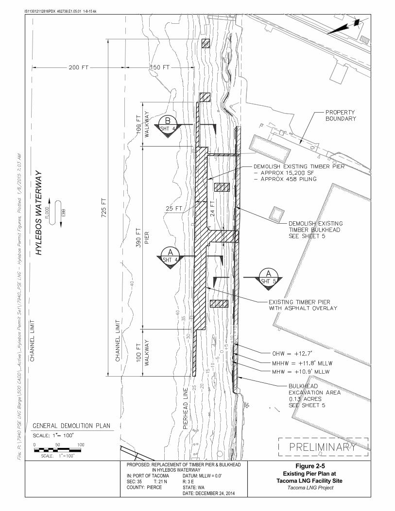
IS113012112816PDX 462738.E1.05.01 1-8-15 kk
DATUM: MLLW = 0.0'R: 3 ESTATE: WADATE: DECEMBER 24, 2014
PROPOSED: REPLACEMENT OF TIMBER PIER & BULKHEAD IN HYLEBOS WATERWAY
Figure 2-5Existing Pier Plan at
Tacoma LNG Facility Site Tacoma LNG Project
IN: PORT OF TACOMA SEC: 35 T: 21 N COUNTY: PIERCE
HY
LEB
OS
WA
TER
WA
Y

IS113012112816PDX 462738.E1.05.01 1-8-15 kk
DATUM: MLLW = 0.0'R: 3 ESTATE: WADATE: DECEMBER 24, 2014
PROPOSED: REPLACEMENT OF TIMBER PIER & BULKHEAD IN HYLEBOS WATERWAY
Figure 2-6Existing Pier Elevation
at Tacoma LNG Facility Site Tacoma LNG Project
IN: PORT OF TACOMA SEC: 35 T: 21 N COUNTY: PIERCE
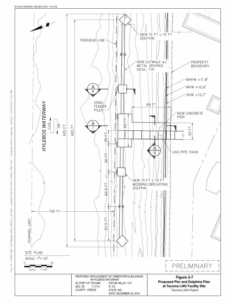
IS113012112816PDX 462738.E1.05.01 1-8-15 kk
DATUM: MLLW = 0.0'R: 3 ESTATE: WADATE: DECEMBER 24, 2014
PROPOSED: REPLACEMENT OF TIMBER PIER & BULKHEAD IN HYLEBOS WATERWAY
Figure 2-7Proposed Pier and Dolphins Plan
at Tacoma LNG Facility Site Tacoma LNG Project
IN: PORT OF TACOMA SEC: 35 T: 21 N COUNTY: PIERCE
HY
LEB
OS
WA
TER
WA
Y

IS113012112816PDX 462738.E1.05.01 1-8-15 kk
DATUM: MLLW = 0.0'R: 3 ESTATE: WADATE: DECEMBER 24, 2014
PROPOSED: REPLACEMENT OF TIMBER PIER & BULKHEAD IN HYLEBOS WATERWAY
Figure 2-8Proposed Pier and Dolphins Elevation
at Tacoma LNG Facility Site—1 of 3 Tacoma LNG Project
IN: PORT OF TACOMA SEC: 35 T: 21 N COUNTY: PIERCE
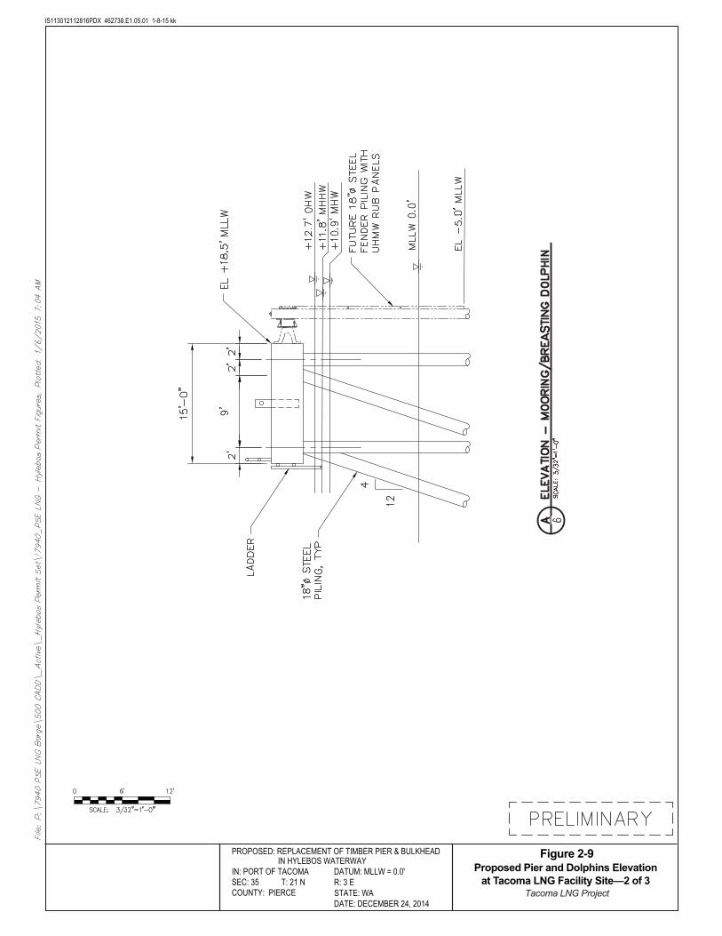
IS113012112816PDX 462738.E1.05.01 1-8-15 kk
DATUM: MLLW = 0.0'R: 3 ESTATE: WADATE: DECEMBER 24, 2014
PROPOSED: REPLACEMENT OF TIMBER PIER & BULKHEAD IN HYLEBOS WATERWAY
Figure 2-9Proposed Pier and Dolphins Elevation
at Tacoma LNG Facility Site—2 of 3 Tacoma LNG Project
IN: PORT OF TACOMA SEC: 35 T: 21 N COUNTY: PIERCE
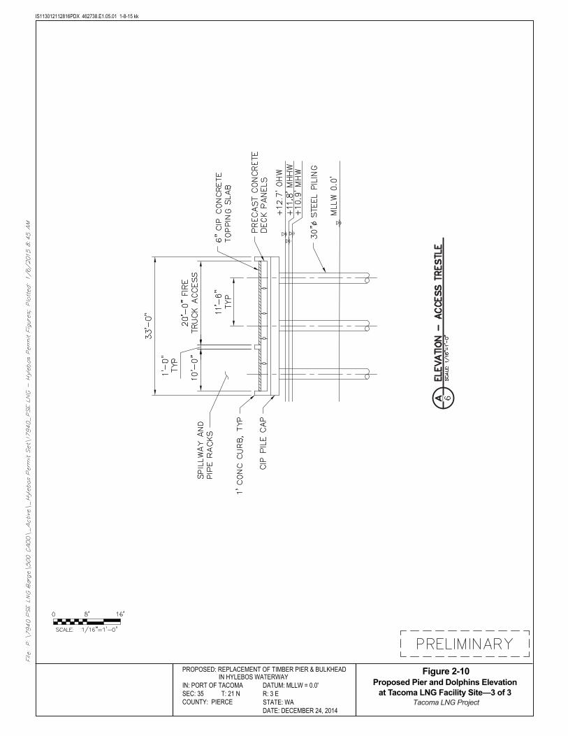
IS113012112816PDX 462738.E1.05.01 1-8-15 kk
DATUM: MLLW = 0.0'R: 3 ESTATE: WADATE: DECEMBER 24, 2014
PROPOSED: REPLACEMENT OF TIMBER PIER & BULKHEAD IN HYLEBOS WATERWAY
Figure 2-10Proposed Pier and Dolphins Elevation
at Tacoma LNG Facility Site—3 of 3 Tacoma LNG Project
IN: PORT OF TACOMA SEC: 35 T: 21 N COUNTY: PIERCE
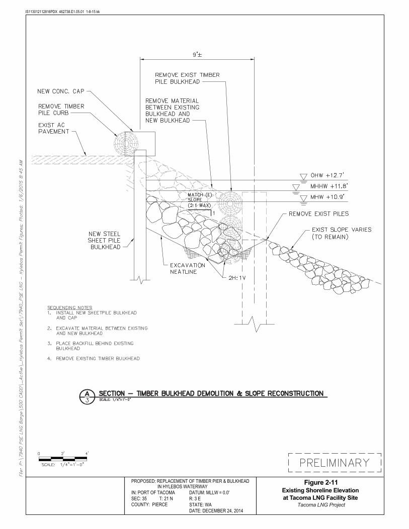
IS113012112816PDX 462738.E1.05.01 1-8-15 kk
DATUM: MLLW = 0.0'R: 3 ESTATE: WADATE: DECEMBER 24, 2014
PROPOSED: REPLACEMENT OF TIMBER PIER & BULKHEAD IN HYLEBOS WATERWAY
Figure 2-11Existing Shoreline Elevation at Tacoma LNG Facility Site
Tacoma LNG Project
IN: PORT OF TACOMA SEC: 35 T: 21 N COUNTY: PIERCE

IS113012112816PDX 462738.E1.05.01 1-8-15 kk
PROPOSED: BLAIR WATERWAY LOADING PLATFORM
DATUM: MLLW = 0.0'R: 3 ESTATE: WADATE: DECEMBER 24, 2014
Figure 2-12Proposed Pier and Dolphins Plan at TOTE Marine Vessel LNG Fueling System Site
Tacoma LNG Project
IN: PORT OF TACOMA SEC: 35 T: 21 N COUNTY: PIERCE
BLA
IR W
ATE
RW
AY

IS113012112816PDX 462738.E1.05.01 1-8-15 kk
PROPOSED: BLAIR WATERWAY LOADING PLATFORM
DATUM: MLLW = 0.0'R: 3 ESTATE: WADATE: DECEMBER 24, 2014
Figure 2-13Proposed Pier Elevation at TOTE Marine Vessel LNG Fueling System Site—1 of 2
Tacoma LNG Project
IN: PORT OF TACOMA SEC: 35 T: 21 N COUNTY: PIERCE
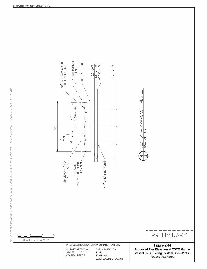
IS113012112816PDX 462738.E1.05.01 1-8-15 kk
PROPOSED: BLAIR WATERWAY LOADING PLATFORM
DATUM: MLLW = 0.0'R: 3 ESTATE: WADATE: DECEMBER 24, 2014
Figure 2-14Proposed Pier Elevation at TOTE Marine Vessel LNG Fueling System Site—2 of 2
Tacoma LNG Project
IN: PORT OF TACOMA SEC: 35 T: 21 N COUNTY: PIERCE
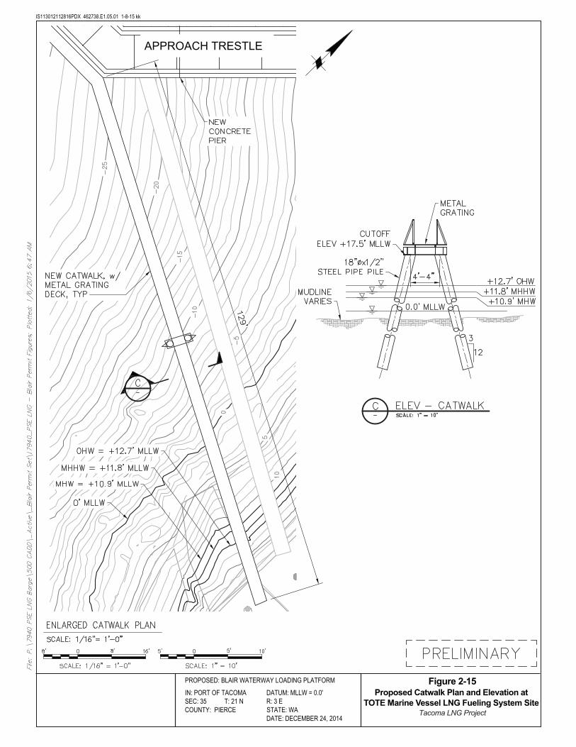
IS113012112816PDX 462738.E1.05.01 1-8-15 kk
PROPOSED: BLAIR WATERWAY LOADING PLATFORM
IN: PORT OF TACOMA DATUM: MLLW = 0.0'SEC: 35 T: 21 N R: 3 ECOUNTY: PIERCE STATE: WA
DATE: DECEMBER 24, 2014
Figure 2-15Proposed Catwalk Plan and Elevation at
TOTE Marine Vessel LNG Fueling System Site Tacoma LNG Project
APPROACH TRESTLE
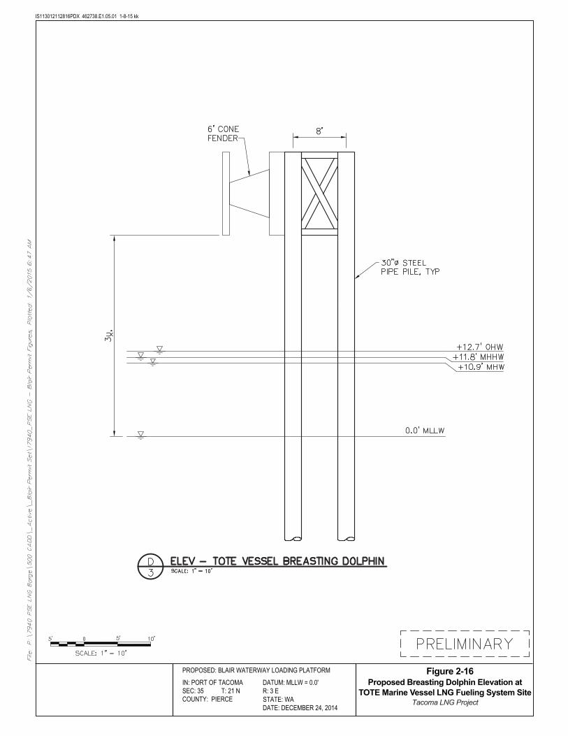
IS113012112816PDX 462738.E1.05.01 1-8-15 kk
PROPOSED: BLAIR WATERWAY LOADING PLATFORM
DATUM: MLLW = 0.0'R: 3 ESTATE: WADATE: DECEMBER 24, 2014
Figure 2-16Proposed Breasting Dolphin Elevation at
TOTE Marine Vessel LNG Fueling System Site Tacoma LNG Project
IN: PORT OF TACOMA SEC: 35 T: 21 N COUNTY: PIERCE

IS113012112816PDX 462738.E1.05.01 1-8-15 kk
PROPOSED: BLAIR WATERWAY LOADING PLATFORM
DATUM: MLLW = 0.0'R: 3 ESTATE: WADATE: DECEMBER 24, 2014
Figure 2-17Proposed Removal of Existing Catwalk at
TOTE Marine Vessel LNG Fueling System Site Tacoma LNG Project
IN: PORT OF TACOMA SEC: 35 T: 21 N COUNTY: PIERCE
BLA
IR W
ATE
RW
AY
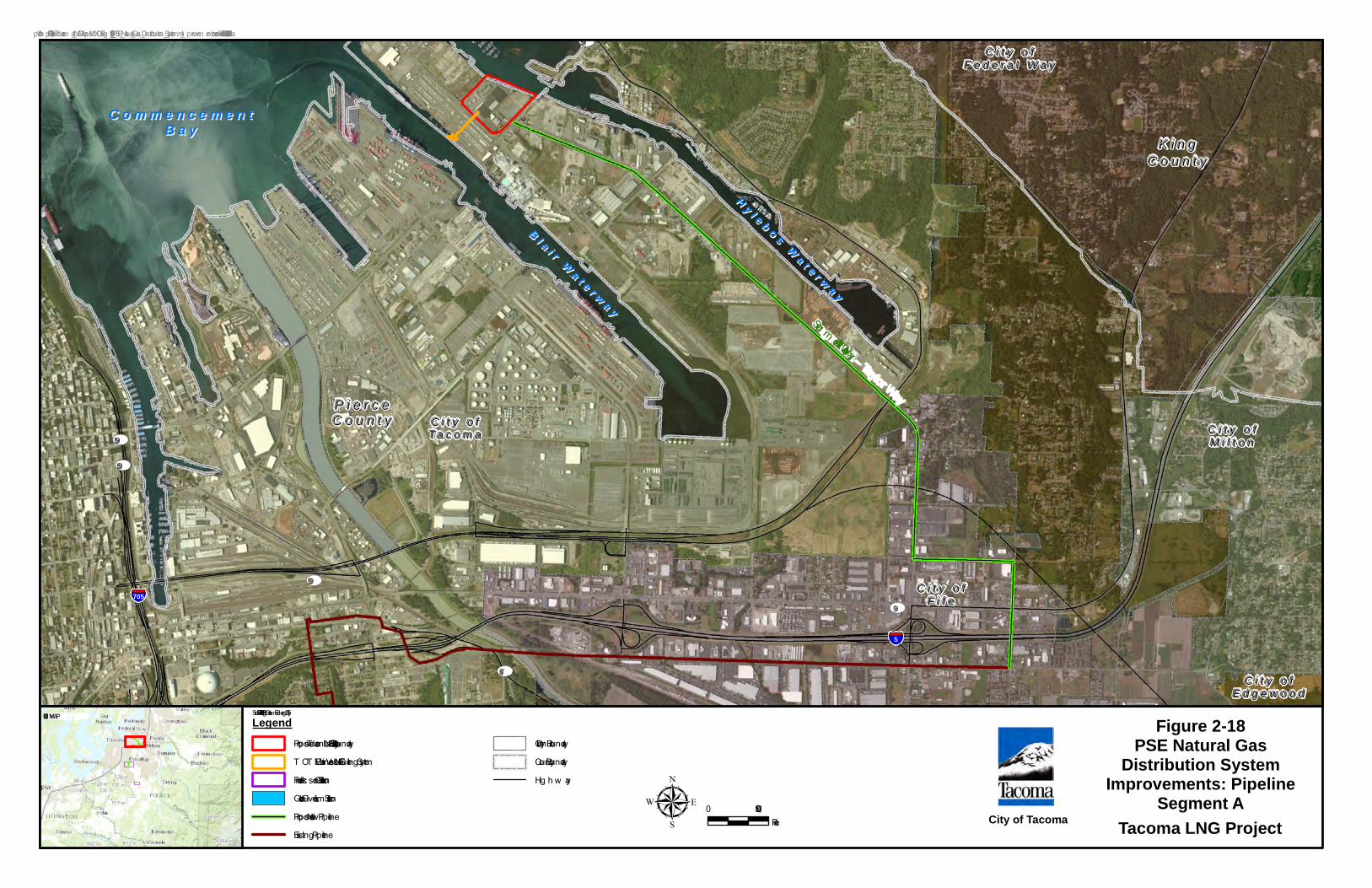
C o m m e n c e m e n tC o m m e n c e m e n tB a yB a y
B l a i r W a t e r w a y
B l a i r W a t e r w a y
H y l e b o s W a t e r w a y
H y l e b o s W a t e r w a y
UV509
UV99
UV509
UV509
UV167
UV509§̈¦705
§̈¦5
K i n gK i n gC o u n t yC o u n t y
P i e r c eP i e r c eC o u n t yC o u n t y
C i t y o fC i t y o fF i f eF i f e
C i t y o fC i t y o fE d g e w o o dE d g e w o o d
C i t y o fC i t y o fF e d e r a l W a yF e d e r a l W a y
C i t y o fC i t y o fM i l t o nM i l t o n
C i t y o fC i t y o fT a c o m aT a c o m a
Seg m ent A – Taylor Way
0 1,500Feetµ
LegendProposed Tacom a LNG Facility Site BoundaryT OT E Marine Vessel LNG Fueling SystemFrederick son Gate StationGolden Given Lim it StationProposed New PipelineExisting Pipeline
City Lim it BoundaryCounty BoundaryHig h w ay
Sources: ESRI 2012, Pug et Sound Energ y 2015
\\prtbh p1\GIS\Portland\Tacom a_LNG\Maps\MXDs\Fig _2-18_-19_-20_PSE_Natural_Gas_Distribution_System _Im provem ents.m xd edw ardsa 4/15/2015 2:21:46 PM
Tacoma LNG Project
VICINIT Y MAP Figure 2-18PSE Natural Gas
Distribution SystemImprovements: Pipeline
Segment ACity of Tacoma

UV7
UV512
P i e r c eP i e r c eC o u n t yC o u n t y
C i t y o fC i t y o fT a c o m aT a c o m a
GoldenGiven Lim itStation
Segment B – Golden Given Road East
0 1,200Feetµ
LegendProposed Tacom a LNG Facility Site BoundaryT OT E Marine Vessel LNG Fueling SystemFrederick son Gate StationGolden Given Lim it StationProposed New PipelineEx isting Pipeline
City Lim it BoundaryCounty BoundaryHigh way
Sources: ESRI 2012, Puget Sound Energy 2015
\\prtbh p1\GIS\Portland\Tacom a_LNG\Maps\MXDs\Fig_2-18_-19_-20_PSE_Natural_Gas_Distribution_System _Im provem ents.m x d edwardsa 4/15/2015 2:21:46 PM
Tacoma LNG Project
VICINIT Y MAP Figure 2-19PSE Natural Gas
Distribution SystemImprovements: Pipeline
Segment BCity of Tacoma
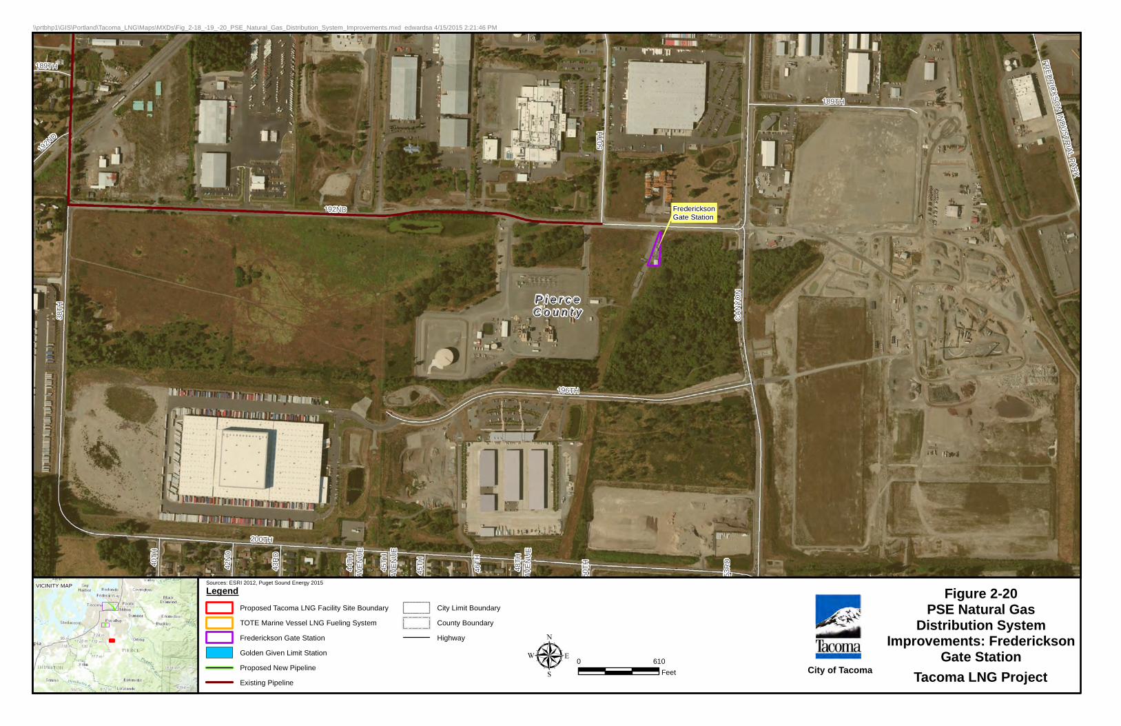
P i e r c eP i e r c eC o u n t yC o u n t y
FRED
RIC
KSON
IND
USTR
IAL PARK
53R
D
46TH
50TH48
THAV
EN
UE
45TH
45TH
AVE
NU
E
44TH
AVE
NU
E
43R
D
42N
D
40TH
189TH38
TH
192N
D
CA
NY
ON
192ND
189TH
196TH
200TH
50TH
FredericksonGate Station
0 610Feetµ
LegendProposed Tacoma LNG Facility Site Boundary
TOTE Marine Vessel LNG Fueling System
Frederickson Gate Station
Golden Given Limit Station
Proposed New Pipeline
Existing Pipeline
City Limit Boundary
County Boundary
Highway
Sources: ESRI 2012, Puget Sound Energy 2015
\\prtbhp1\GIS\Portland\Tacoma_LNG\Maps\MXDs\Fig_2-18_-19_-20_PSE_Natural_Gas_Distribution_System_Improvements.mxd edwardsa 4/15/2015 2:21:46 PM
Tacoma LNG Project
VICINITY MAP Figure 2-20PSE Natural Gas
Distribution SystemImprovements: Frederickson
Gate StationCity of Tacoma

Figure 2-21Tacoma LNG Facility
Demolition Plan
H y l e b o s W a t e r w a y H y l e b o s W a t e r w a y
Proposed Storage Building
Proposed
Storage
Building
Proposed ControlBuilding
0 100 200Feetµ
LegendProposed New Pipeline
Proposed Tacoma LNG Facility Site Boundary
City Limit Boundary
Structures to be Demolished
Sources: ESRI 2012, Puget Sound Energy 2015
\\prtbhp1\GIS\Portland\Tacoma_LNG\Maps\MXDs\Fig2-21_Demolition_Plan.mxd edwardsa 4/15/2015 2:05:51 PM
Tacoma LNG Project
VICINITY MAP
City of Tacoma
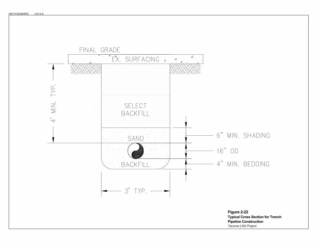
ES071414023944PDX 4-24-15 lb
Figure 2-22Typical Cross Section for Trench Pipeline ConstructionTacoma LNG Project