
2.1 CONSTRUCTION AND STRUCTURAL STRENGTH … · parts of BS 3532:1990, BS EN 14118:2003, BS EN ISO...
37
MSIS 27/CH 2/Rev 1017/Page 1 of 37 CHAPTER 2 - CONSTRUCTION, WATERTIGHT AND WEATHERTIGHT INTEGRITY INTRODUCTION This Chapter should be read in conjunction with Chapter 2 of the MSN 1872 and MSN 1873. The guidance should also be applied, as far as practical, to vessels complying with the ‘Code of Practice for the Safety of Small Fishing Vessels MSN 1871 ’ (Under 15m Code). 2.1 CONSTRUCTION AND STRUCTURAL STRENGTH 2.1.1 General Requirements for Construction and Structural Strength The structural strength and construction and the disposition of bulkheads should be adequate for all foreseeable operating conditions in service. The scantlings, arrangements and construction for the hull, bulkheads, superstructures, deckhouses, machinery casings, companionways and other structures should be sufficient to withstand all operational loads arising during the vessel’s service, to the satisfaction of the MCA or Certifying Authority or Classification Society. 2.1.1.1 New vessels 2.1.1.1.2 The owners should inform the MCA if the vessel is to be operated in areas subject to sea ice conditions. Hull construction and stability requirements will be specially considered for vessels operating in such areas. 2.1.1.1.3 When vessels are built to a Certifying Authority or Class requirements, the MCA should be provided with a set of approved main structural plans. On completion, the Certifying Authority or Class should submit a ‘Partial declaration of survey’ (form MSF1326 or MSF1333, as appropriate) to the MCA. 2.1.1.1.4 MGN322 requires new vessels of 24m and over to be built and maintained in class. 2.1.1.2 Existing vessels flagging-in 2.1.1.2.1 The Under 15m Code does not specify any hull structure requirements, but as a minimum, the MCA requires vessels to comply with the relevant Seafish standards. This is normally by a condition survey/inspection carried out by a Seafish authority surveyor, or delegated surveyor. The resulting report should be forwarded to the regional Consultant Surveyor, for a decision on whether to accept, accept with conditions or reject the report and vessel. 2.1.1.2.3 Usually, vessels under the 15 -24m Code are not classed but have been built to the standards of a Certifying Authority. Before such vessels can flag-in, details should be submitted to the MCA indicating that the vessel has been constructed to such a recognised standard. Note that it may be necessary for an inspection to be carried out, prior to flag-in, to confirm that the vessel complies with the relevant construction standards, e.g. by a Certifying Authority or other suitably competent surveyor.
Transcript of 2.1 CONSTRUCTION AND STRUCTURAL STRENGTH … · parts of BS 3532:1990, BS EN 14118:2003, BS EN ISO...
MSIS 27/CH 2/Rev 1017/Page 1 of 37
CHAPTER 2 - CONSTRUCTION, WATERTIGHT AND WEATHERTIGHT INTEGRITY INTRODUCTION This Chapter should be read in conjunction with Chapter 2 of the MSN 1872 and MSN 1873. The guidance should also be applied, as far as practical, to vessels complying with the ‘Code of Practice for the Safety of Small Fishing Vessels MSN 1871 ’ (Under 15m Code). 2.1 CONSTRUCTION AND STRUCTURAL STRENGTH 2.1.1 General Requirements for Construction and Structural Strength The structural strength and construction and the disposition of bulkheads should be adequate for all foreseeable operating conditions in service. The scantlings, arrangements and construction for the hull, bulkheads, superstructures, deckhouses, machinery casings, companionways and other structures should be sufficient to withstand all operational loads arising during the vessel’s service, to the satisfaction of the MCA or Certifying Authority or Classification Society. 2.1.1.1 New vessels 2.1.1.1.2 The owners should inform the MCA if the vessel is to be operated in areas subject to sea ice conditions. Hull construction and stability requirements will be specially considered for vessels operating in such areas. 2.1.1.1.3 When vessels are built to a Certifying Authority or Class requirements, the MCA should be provided with a set of approved main structural plans. On completion, the Certifying Authority or Class should submit a ‘Partial declaration of survey’ (form MSF1326 or MSF1333, as appropriate) to the MCA. 2.1.1.1.4 MGN322 requires new vessels of 24m and over to be built and maintained in class. 2.1.1.2 Existing vessels flagging-in 2.1.1.2.1 The Under 15m Code does not specify any hull structure requirements, but as a minimum, the MCA requires vessels to comply with the relevant Seafish standards. This is normally by a condition survey/inspection carried out by a Seafish authority surveyor, or delegated surveyor. The resulting report should be forwarded to the regional Consultant Surveyor, for a decision on whether to accept, accept with conditions or reject the report and vessel.
2.1.1.2.3 Usually, vessels under the 15 -24m Code are not classed but have been built to the standards of a Certifying Authority. Before such vessels can flag-in, details should be submitted to the MCA indicating that the vessel has been constructed to such a recognised standard. Note that it may be necessary for an inspection to be carried out, prior to flag-in, to confirm that the vessel complies with the relevant construction standards, e.g. by a Certifying Authority or other suitably competent surveyor.
MSIS 27/CH 2/Rev 1017/Page 2 of 37
2.1.1.2.4 Vessels >24m should generally be built to and maintained ‘in class’, for consideration of flagging-in. In such cases, surveyors should obtain a copy of the valid certificate of class, and confirmation from the owner that the vessel will remain ‘in class’. Such confirmation should be in the form of a statement, setting out the penalty if the vessel is withdrawn from class or becomes unclassed both before registration is completed and afterwards, prepared by the surveyor, and signed by the owner. In addition, the Certifying Authority surveyor should be requested to complete a ‘Record of particulars’ (form MSF1301) and ‘Partial declaration of survey’ (form MSF1333) and return them to the MCA, prior to registration. The forms should be retained on file. 2.1.1.2.5 Confirmation of equivalent standards will be required for any unclassed vessels. This will normally involve the submission of plans and full supporting calculations, but may also involve the use of other organisations, to undertake work on behalf of the MCA. Owners and builders should be made aware that they will be responsible for all costs associated with such verification work. 2.1.1.2.6 Exceptional cases where classification is not appropriate, should be dealt with on a case-by-case basis. To ensure consistency in the application of ‘equivalent standards’, such decisions should be made by the MCA ‘Flag-in panel’. 2.1.1.2.7 Existing vessels that have not been MCA certificated for at least the previous 6 months should be treated, in general, as a vessel flagging-in, with no exemptions. Confirmation of compliance, with the applicable standards, will be required before these vessels can be re-certificated by the MCA. 2.1.1.3 Surveys 2.1.1.3.1 Existing vessels >24m which are classed should be maintained ‘in class’, to ensure compliance with adequate standards. 2.1.1.3.2 Vessels that are unclassed should be surveyed annually, as detailed in MGN 322 and MGN 439. Existing unclassed vessels should comply with the following survey requirements.
Unclassed Vessel Flag State Survey (4 year cycle) Survey items; entire vessel;
Initial Survey Annual Intermediate* Annual Renewal**
Year 0 1 2 3 4
Range dates 0 + 3m + 3m + 3m -3m
* 2 bottom inspections should be carried out within a 4 year period of validity of the certificate. The Intermediate and Renewal Surveys for unclassed vessels should include a bottom inspection, but the bottom inspection may be deferred for up to 12 months, subject to satisfactory inspection at the intermediate or renewal survey. If the period between bottom inspections has been extended by 12 months, the next bottom inspection should be carried out within 12 months to ensure that the bottom inspection is normally carried out during the renewal or intermediate surveys. ** Renewal survey can be completed up to 3 months prior to expiry of the certificate

MSIS 27/CH 2/Rev 1017/Page 3 of 37
Classed Vessel Class Survey (5 year cycle) Survey items; Hull, Machinery, Electrical and Control
Initial Survey Annual Annual/ Intermediate
Annual/ Intermediate
Annual Renewal
Year 0 1 2 3 4 5
Range dates 0 + 3m + 3m + 3m + 3m -3m
Flag State Survey (4 year cycle) Survey items; stability, LSA, FFE, SFP, crew safety and comfort, all remaining items)
Initial Survey Annual Intermediate Annual Renewal**
Range dates 0 n/a + 3m n/a -3m
** Renewal survey can be completed up to 3 months prior to expiry of the certificate
2.1.1.3.3 Classification societies should notify the MCA of any vessels that have had their class suspended or withdrawn and any statutory certificates, relating to the construction, would become cancelled, until such time as the vessel is ‘re-classed’ by a recognised classification society. 2.2 Material of construction 2.2.1 New vessels should be constructed of wood, fibre reinforced plastic (FRP), aluminium alloy or steel or appropriate combinations of such materials. Proposals to use any other construction material should be submitted to Vessel Standards Branch for special consideration and approval. 2.2.2 Existing vessels can be considered to be of acceptable structural strength if it is determined type and characteristics of the material used and the method of construction are acceptable that it is in a good state of repair. Fibre-reinforced plastics 2.2.3 When it is intended to use glass-reinforced plastics in the construction of a vessel, details of the extent to which the material is to be used should be submitted well in advance of the date it is proposed to commence work. Depending on the extent to which the material is to be used, further details may be required of the resins, fillers, and glass fibre reinforcements which should comply with the relevant parts of BS 3532:1990, BS EN 14118:2003, BS EN ISO 3691:2009 and BS 3396 and BS 3749:1991, and are to be acceptable to the MCA. 2.2.4 The MCA will require to be satisfied that the premises are suitable, and that persons who are employed have been properly trained for the type of work to be undertaken. 2.2.5 Whenever glass-reinforced plastic is used in the construction of the hull, decks, superstructure, deckhouses or bulkheads, the laminates should be self extinguishing from fire considerations. The self extinguishing property should be imparted to the whole of the laminate. The test method to be used for ensuring that this requirement is complied with is described in Appendix E to the ‘Passenger ship construction classes III to VI(A) - Instructions to surveyors’. 2.2.6 Should it be proposed to construct the hull, decks, superstructure, deckhouses or bulkheads with special laminates to afford the same degree of

MSIS 27/CH 2/Rev 1017/Page 4 of 37
protection against fire as that obtained by the use of self extinguishing laminates, full details should be submitted for consideration. 2.2.7 Vessels may also be of composite construction with, e.g. a glass-reinforced plastic hull, but incorporating frames, decks, bulkheads, engine bearers, longitudinal members and superstructures of wood, steel or other material. 2.3 Structural alterations 2.3.1 Structural alterations to existing vessels should be, in general, to the same standard as for a new vessel. Where a vessel is classed, the classification society should confirm approval of the alterations and continuation of classification. 2.3.2 Owners should be reminded that structural alterations to a vessel may alter the stability characteristics and this must be taken into consideration. 2.4 Submission of Plans and Particulars 2.4.1 The hull construction and arrangement drawings should be examined and approved, as complying with the requirements of the relevant Code, by the Certifying Authority or the MCA, as appropriate. 2.4.2 All plans, particulars and calculations should be; (a) in English, or include an adequate translation, (b) metric measurements, (c) identify the materials being used and their means of connection, particularly where it is intended to use steels of special quality and aluminium alloy. 2.4.3 Surveyors should acknowledge receipt of plans and documents and make every endeavour to ensure an expeditious return of submitted plans and documents and/or comments appropriate to them. 2.4.4 The hull should be surveyed during construction by the Certifying Authority or the MCA, as appropriate, to verify compliance with the approved drawings. The attending Surveyor should be satisfied with the quality, strength and testing of the materials used in the construction of the hull, bulkheads, decks, superstructures and deckhouses; and the materials used in the attachments thereto. An appropriate certificate of construction should be issued on completion of build. 2.4.5 For Under 15m vessels built since 16 July 2007, and registering as a fishing vessel for the first time, the construction and outfit must conform to the recognised standard of a Certifying Authority for small Fishing Vessels or an equivalent standard recognised by the MCA as suitable for Fishing Vessels. Failure to do so will result in the vessel not being registered, On first registration of a these vessels, the owner shall supply the required hull construction and outfit certificates to the Registry of Shipping and Seamen (RSS), together with the Small Fishing Vessel Certificate in order that the vessel can be registered. 2.4.6 For under 15m vessels built prior to 16 July 2007, owners will be required to prove that the condition of the vessel is satisfactory. This is carried out through a Certifying Authority who will complete a registration inspection. This inspection will examine the vessel’s structure, and in the case of vessels of 7m and over, their outfit,

MSIS 27/CH 2/Rev 1017/Page 5 of 37
against a Certifying Authority’s standard for small fishing vessels. The MCA will then examine the Certifying Authority’s Inspection Report, and either allow registration or require the owner to address areas of concern. Registration will not be allowed to proceed until areas of concern have been addressed to the satisfaction of the MCA and the Certifying Authority. When registering the vessel the owner shall supply the Inspection Report from the Certifying Authority and the Small Fishing Vessel Certificate to RSS in order that the vessel may be registered. Alternatively, the vessel should comply with an equivalent standard recognised by the MCA as suitable for fishing vessels.
2.4.7 Under 15m vessels that have previously been on the UK Register, but that are currently off the Register for any reason and apply to re-register after a period of 6 months or more have elapsed since they left the Register will be treated in accordance with 2.4.6 (section 3.11 of MSN 1871) above, regardless of the age of the vessel.
2.4.8 For all under 15m vessels (whether new build or not), an MCA safety inspection must follow the Certifying Authority’s registration inspection. The MCA inspection will cover the requirements of this Code, the crew qualifications, and any other mandatory requirements.
2.4.8 To Register an Under 15m Fishing Vessel built since 16 July 2007 the following is required:
Vessel Length Hull
Construction
Certificate
issued by a
Certifying
Authority
Outfit
Compliance
Certificate
issued by a
Certifying
Authority
Safety
Checklist
(Annex
1.1-1.6)
Stability
Information
Under 7
metres (LOA) Yes Recommended Yes Recommended
7 metres (LOA) to less
than 12 metres (L)
Yes Yes Yes Recommended
12 metres (L)
to less than15
metres (LOA)
Yes Yes Yes Yes
3.6 To register a fishing vessel built before 16 July 2007, the following is
required;
Vessel Length Registration
Inspection by a
Certifying
Authority
Safety
Checklist
(Annex 1.1-1.6)
Stability
Information
Under 7 metres Yes Yes Recommended

MSIS 27/CH 2/Rev 1017/Page 6 of 37
(LOA)
7 Metres
(LOA) to less
than 12 metres
(L)
Yes Yes Recommended
12 metres (L) to
less than 15
metres (LOA)
Yes Yes Yes
2.4.9 Vessels of 15-24m registered length should be constructed in accordance with the Certifying Authority requirements. Generally, the Certifying Authority should supervise the construction of the vessel and provide the MCA, on completion, with a declaration stating that the vessel complies with the applicable requirements and, in addition, any more onerous MCA requirements. 2.4.10 All vessels of >24m in length should be built to classification society rules and remain ‘in class’ whilst a UK registered fishing vessel. The surveyor should be provided with copies of the classification society approved structural plans. MGN 322 includes a typical list of such plans and MCA should be supplied with copies of plans. 2.5 Surveys 2.5.1 Surveyors should satisfy themselves at renewal surveys that the hull, and skin fittings, are in good condition, that the principal structural scantlings are maintained, that the arrangements and details are in accordance with MCA requirements and the vessel is in all respects fit for its intended service. Any proposals for altering the structure that may affect the main or local strength of the vessel must be submitted for consideration. In the case of a classed vessel, the surveyor should obtain a copy of the classification society's letter to the owner or ship-repairer approving the proposals for the alteration, and place it on the vessel's file for record purposes together with a stamped approved copies of any associated plans. 2.5.2 The surveyor should make a thorough examination of the outside of the hull, generally on a slipway or in a dry dock, after it has been cleaned but before it is painted or otherwise coated. Sufficient clearance should be arranged under the hull to allow ease of access with adequate artificial lighting provided to the surveyors satisfaction. Access to the upper parts of the outside of the hull and around the rudder should be by means of a safe arrangement of scaffolding and associated ladders securely fastened in way to meet statutory safety standards. 2.5.3 Under exceptional circumstances, such as an emergency situation, the vessel may be placed on blocks on a clean, hard beach that may require the vessel to be listed, such that satisfactory inspection of every part of the hull can be made. 2.5.4 In general, all repairs should be to the same standard and material as the original structure. For this reason, the application of a glass-reinforced plastics skin, to the inner and outer hull of a wooden boat, cannot be considered to be anymore than a simple form of coating. This method of ‘repair’ is not considered to be structural, as
MSIS 27/CH 2/Rev 1017/Page 7 of 37
the strength of the boat is still reliant on the original wooden framing and planking, and their connections. 2.6 Steel vessels 2.6.1 All external areas of the hull plating and means of connection, should be examined, e.g. for damage, corrosion pitting, welding failure, rivet head wastage. Internally, the hull plating, framing and means of connection, in double bottoms, holds, ‘tween decks, peaks and machinery spaces, should be examined. Freeboard/weather deck and superstructure deck plating and beams, should be examined. 2.6.2 Surveyors should carry out a detailed examination of the outer hull, in particular;
• the ‘wind and waterline’,
• any fishroom bilge sump,
• the bottom and keel area, for any signs of grounding damage,
• areas in way of fishing gear, e.g. trawl doors or clam dredges etc,
• bilge keels and their connection to the hull,
• welds, for wear or electrolytic erosion,
• plates, in general, for electrolysis or for localised pitting (possible when earth fault present)
• any riveted butts and seams,
• bow areas, for contact damage,
• areas around previous repairs, particularly if repairs were due to reduced hull thickness,
• any doubler plates, or other un-reported repairs,
• gut and stone chutes bottom plating that form part of the hull, as these areas are particularly prone to wear,
• sacrificial anodes, and
• discharge pipes from toilets/sewage units. 2.7 Plate thickness 2.7.1 Non-destructive testing (NDT) plate thickness readings, of the hull plating at the ‘wind and waterline’ and at L/4 bands, should be taken at every re-survey. However, surveyors require only random thickness checks to be taken, after a satisfactory visual examination, at the first re-survey of a vessel. Additional readings should be taken in any suspect areas highlighted by the surveyor for particular examination e.g. fish room bilge sump, any damaged areas, and any other areas where signs of corrosion or thinning are evident. Normally about 5 readings per plate are sufficient, with a additional readings in any highlighted areas. Preferably any paint should be removed to bare steel and, in areas of severe pitting, the pits ground flush to achieve accurate readings. The deck plating should be similarly tested. 2.7.2 The testing should be carried out by a competent person, normally approved by a Classification Society, preferrably with the surveyor present. A copy of the thickness report should be placed on file.

MSIS 27/CH 2/Rev 1017/Page 8 of 37
2.7.3 If the surveyor has any doubts about the plating thickness, a further examination should be requested and, in borderline cases, drill tests undertaken, i.e. a hole drilled through the plating, and the plate thickness physically measured, following which the hole is sealed up by welding.
2.7.4 In general, the maximum allowance for wastage is of 25% of original design thickness (consequently, original scantlings should be available). 2.7.5 In general, vessels built to one of the MCA recognised classification societies rules should comply with the following corrosion limits.
Within L/2 midships Elsewhere
Length >100m Length <100m Length >100m Length <100m
Plating: Bottom 10% 15% 20% 30%
Topsides 10% 15% 25% 30%
Stiffeners: Bottom 10% 20% 20% 30%
Topsides 15% 20% 25% 30%
2.7.6 Local plating strength for steel may be assessed according to the following formula: t = 0,004 × s × √h + c t = minimum plate thickness (mm) s = stiffener spacing (mm) h = pressure head (m) (taken to 1m above the deck)
c = corrosion allowance, e.g. for coated steel, min 2mm for period between surveys is > 4yr
Based on a max yield stress in steel of 235N/mm2, but only applicable to plating subject to hydrostatic pressures only. 2.7.7 Isolated areas of pitting, with a depth not exceed 50% of the plate thickness, may be repaired by welding, subject to the use of qualified welders, and approved procedures and materials, e.g. classification society approved. In general, hull plate areas below 3mm in thickness should be renewed. Renewed plates should be of sufficient size to reduce problems of excessive stress being locked in, due to shrinkage on cooling. Where the extent of pitting is considered excessive in areas, e.g. >10% of plate area, or due to the depth, the risk of heat distortion or cracking will increase and the defective plate should be cropped out and renewed. Such repairs may require NDT on completion, to the surveyors satisfaction.
2.7.8 Doubling plates are normally only acceptable as a temporary repair, in certain circumstances, e.g. to increase the strength of plating and stiffeners but not on bottom plating (excluding temporary repairs) and only if there is sufficient material in the parent plate to effect an effective weld. Details of the fitting of doubler plates, e.g. welding, plate size, etc should be to classification society requirements. The welding detail requires special attention. Surveyors should ensure that they have the

MSIS 27/CH 2/Rev 1017/Page 9 of 37
necessary competence before surveying such repairs. Any doubler plates fitted should be tested and the owner advised of the time limit affect permanent repairs. 2.7.9 Surveyors should carry out a detailed internal examination, in particular the plating, framing and means of connection etc. in ballast tanks, double bottom tanks, holds, between decks, peaks and machinery spaces. In other spaces ceiling sparring, linings and insulation should be removed, where necessary, to enable inspection of shell plating and frames etc. to be carried out. The plating and beams of the freeboard/weather and superstructure decks should be surveyed. Areas where any pockets where water may accumulate should be particularly examined and limber/drain holes exposed. 2.7.10 Areas below floor plates and around bilge wells should also be examined (if practical a hose test should be carried out, e.g. from forward and aft of engine room bulkheads). 2.7.11 Where loose ballast is stored in any space a portion should be removed to check that no chafing has taken place. 2.8 Wooden vessels 2.8.1 All external areas of the keel and planking should be examined, for damage, rot, etc. Caulking of garboard and other seams should be thoroughly tested. Internally, the hull (moulding, plating or planking), framing and means of connection, in double bottoms, holds, ‘tween decks, peaks and machinery spaces, should be examined. Freeboard/weather deck and superstructure deck structures (moulding, plating or planking and beams) should be examined. Surveyors should take account of what is observed on the outside of the vessel, when surveying the inside. Prior to carrying out a detailed examination of the outer hull, the surveyor should look inside the vessel and determine those areas that require to be opened up to facilitate examination of the inner hull. The amount of opening up required will initially be determined by what has been observed up to this point, although further opening up may be required depending upon what is subsequently observed.
2.8.2 If a vessel is found at inspection to have been sheathed then the
vessel is to be seen out of the water to check for the adhesion and any
breaks in the coating.
The hull is to be sounded and probed for soft wood. The term sounding
refers to tapping with a hammer to judge the soundness of the material and
the tightness of fastenings and fittings. The term probing refers to the
use of a thin, sharp pointed steel probe that is pressed into the timber.
If the timber is sound the probe will not penetrate, but if decay is
present, the probe will penetrate, and the ease and depth will reflect the
degree of decay to the experienced inspector.
2.8.3 It is imperative that indiscriminate probing and boring be
avoided. Holes made by a probe or drill in the hull exterior are potential
entry ways for marine borers. In the hull interior they allow easier
moisture penetration and thus aid in starting decay. Probing and boring

MSIS 27/CH 2/Rev 1017/Page 10 of 37
should be done carefully and only where there is an indication from non-
destructive testing that the hull is unsound, not as a matter of routine.
2.8.4 Internally the vessel is to be checked adequate ventilation.
2.8.5 On successful survey only, the owner is to be advised that the
vessel be permitted to remain on the register for five years, after which
it will be de-registered.
2.8.6 Surveyors should carry out a detailed examination of the outer hull, in particular;
(a) the keel should be examined for any signs of damage from grounding, working of the scarfed joints etc. and signs of softness or infestation particularly in way of end grain, including the deadwood;
(b) the hull planking should be examined; to ensure that seams are tight,
there are no indications of leaks and no signs of collision or other damage, that may affect the hull strength. No caulking material should be visible. If it is visible, the area has either been incorrectly caulked, needs re-caulking or the plank edges are worn and may require to be replaced. Plank butt blocks should be checked to ensure they are secure and that fastenings in general are sound;
(c) the planking, from garboard to gunwhale, should be examined. Plank
seams should be examined to assess the condition of the caulking and paying compound, checking for softness of the plank edge and any signs of infestation. Each plank should be hammer tested every ~1,5m and caulking thoroughly checked, by screwdriver or similar tool, fore and aft and up to the deck level;
(d) the hull should also be examined for signs of tingles (local patches,
often of thin copper or lead) over the seams, an indication of problems with leaks. When a tingle plate is found on a seam, (usually a seam just forward of the stern gland), it is common to find the area has been frequently re-caulked, unsuccessfully, and the tingle plate has become the best option available, (note that these should be considered a temporary measure only and permanent repairs should be completed as soon as possible);
(e) attention should be given to areas of end grain exposure (hood ends,
butt joints, around hull penetrations etc.) as they are prone to rot and infestation by marine borers. Difficult to paint areas are particularly prone to this, e.g. behind keel coolers, keel strap to keel connections and under inlet grids, such areas often remain unpainted year after year. Also particularly prone are vessels left for periods exceeding one year between painting. The vessels operating location can also be a factor, as some docks and quays are more affected by rot than others. Internal areas with poor air circulation will also generally give ideal conditions for rot to develop. In areas where rot is suspected, but

MSIS 27/CH 2/Rev 1017/Page 11 of 37
there is no indications of a problem with movement or fastenings, then any rot present is unlikely to be causing a significant weakening of the structure,
(f) butt joints should also be examined for signs of splitting at the
fastenings and fairness of the butts. If butts are not flush then the fastenings and/or the timber in way of the fastenings may have deteriorated and should be carefully examined. The condition of the hood ends, and associated fastenings, should be exposed and examined, together with the associated caulking. Areas around inlets and discharges should be examined for softness,
(g) fastenings should only be removed for examination where there is clear evidence of problems (e.g. signs of rust, nail sickness, loose fastenings or timbers etc.) or where there is no clear evidence of examination in the past 5 years. In such cases, an adequate number of fastenings, usually in every fourth timber of bilge planking, on each side should be drawn out, at various parts of the hull, and examined to ascertain their condition and that of the timbers through which they pass. If the vessel is iron fastened, a number of bolts should be driven out, with at least 6 taken from the lower deck bindings on each side. Where such a sample indicates no or only minor problems, no additional fastenings need be removed. If serious problems are evident then additional fastenings should be removed, to establish the extent of the problem. If these fastenings also show signs of serious problems then the surveyor should consider examining a random sample of fastenings over a larger area, in an attempt to establish if the problem extends to the entire vessel. Prior to removal of fastenings, nail heads which show rust trails should be exposed, then hammer and punch tested, this will usually give an indication of the fastenings condition. Where fastenings shatter or break up on being struck the most appropriate action is to arrange for adjacent re-nailing rather than fastening removal.It should be noted that electrolysis can occur in wooden vessels resulting in wastage of the fastenings. This is likely to happen if the main engine etc. has not been correctly earthed, or the hull earthing plate (often a square plate about 500mm x 500mm) is painted over,
(h) if fitted, one chain plate bolt should be backed out, abreast of each rigging and, if in an unsatisfactory condition, additional bolts backed out, as considered necessary. Where metal sheeting is fitted, one sheet from the upper turn of bilge should be stripped off on each side, in line with any rigging, to permit examination,
(i) vessels that have been regularly tied-up along side with other vessels
may have been subject to squeezing, resulting in possible caulking and fastening damage, and will require careful examination of the caulking and fastenings,
(j) it should be noted that hog, particularly in older vessels, is not
necessarily an indication of a hull strength problem, but evidence of

MSIS 27/CH 2/Rev 1017/Page 12 of 37
sag usually is a sign of reduced hull strength. Surveyors should carefully examine vessels for any indication of transverse hog as this can be a sign of inadequate strengthening inside and possible cracks to frames at or around the keel line,
(k) it should also be noted that anodes attached to hull steelwork on
wooden vessels, such as boxed keels, steel sheathing and rudders should be maintained in good conidtion,
(l) the hull framing and deck beams, particularly at the ends, beam shelf,
lodging and hanging knees etc. and floors should be examined for any indications of rot or collision damage. Limber holes should be checked to ensure that they are not blocked and that there is no significant rot or softness of the wood in way of limber holes. Frames and floor connections to the keel and the keel bolts should also be examined. If there appears to be significant signs of corrosion or indications of movement in the bolts then consideration should be given to removing a sample to assess their condition. Stem and stern structures should be examined internally for any signs of contact damage,
(m) the deck planking should be examined as in (b) above, (n) the bulwarks, decks and any deckhouses should be examined and the
surveyor should be satisfied with their condition and strength. Particular areas to look out for include:
(i) where water may collect resulting in rot, (ii) caulking of decks especially in way of deck fittings and
connections at deckhouses, (iii) springing of the deck that may indicate loose fastenings or loss of
strength in the deck planking/framing, (iv) raised plank butts or covering boards, (v) stanchions and frame tops that may appear to be sound but could
be hollowed out, (vi) connection between deck and deckhouse or hatch coaming, and (vii) areas in way of drains and inside any deck lockers.
2.8.7 Surveyors should carry out a detailed internal examination. If the vessel is fitted with concrete ballast, or other permanent ballast with a concrete capping, the edges of the concrete should be firm next to the planking. Any cracking or gaps at the edges could lead to problems with fastenings and signs of rust may be an indication that problems already exist with the fastenings. 2.9 Fibre-reinforced plastic vessels

MSIS 27/CH 2/Rev 1017/Page 13 of 37
2.9.1 All external areas of the moulded hull should be examined, e.g. for damage, gel coat cracking, osmosis, blistering. Surveyors should note any deterioration, e.g. delamination, fractures, osmosis etc. of the components of the laminate particularly in the vicinity of bolt holes, in order to ascertain if the material is suitable to withstand the imposed loads. With vessels of sandwich construction, particular attention should be given to the possibility of delamination. Internally, the hull moulding and framing should be examined. Freeboard/weather deck structures should similarly be examined. Surveyors should examine the vessel carefully both afloat and out of the water and report on the condition describing the appearance of the vessel and the general overall condition. The report should indicate if structural alterations or renewals have been made since the last survey and give detailed information on the condition of the following items;
(a) hull, including outer shell, and hull connections with other structural components; (b) fastenings, primary and secondary bonds and bonded joints; (c) decks, waterways and sheer strake; (d) deck and hold beams and knees; (e) floors, frames and longitudinals; (f) apron and breasthooks, etc; (g) keelson and sister keelsons; (h) hatchways, hatch coamings and hatchway fittings; (i) deck openings, skylights, ventilators and companionways; (j) superstructures and structures which cover deck openings; and (k) engine bearers.
2.9.2 If the details of the materials used in construction are not already on file, they should be reported, as far as can be ascertained, plus the general quality of workmanship.
2.9.3 The fastenings in all types of fibre-reinforced plastic vessel should be carefully examined and where bolt fastenings are used for any connection the surveyor should consider the removal of a sample of bolts for examination at time of survey.
2.10 All vessels 2.10.1 The rudder and all other outside fittings and their fastenings should also be examined. 2.10.2 A surveyor may require any part of the ceilings, linings, deck covering, etc to be removed, and any tank opened up and cleaned as considered necessary, to

MSIS 27/CH 2/Rev 1017/Page 14 of 37
permit a proper examination of the vessels structure. Limbers and air courses should be removed and holds cleared, prior to surveys. 2.10.3 Portions of the deck planking, composite or tiling should be removed where deterioration is evident or suspected. 2.10.4 At new and renewal surveys, all tanks, that are an integral part of the hull, should be internally examined and pressure tested, with either liquid or air to a pressure equivalent to the maximum load experienced in service, oil fuel tanks 300mm greater than maximum head or 1bar if heated, others to top of air pipe (maximum air pressure should not exceed 0,2bar over pressure). 2.10.5 Oil fuel tanks need not be examined internally at every renewal survey; (a) unless as a result of an external examination, (b) once the vessel is 12 years old, or (c) for any other reason the surveyor considers it necessary. Cross-levelling arrangements, if provided, should be examined at every renewal survey. 2.10.6Tanks used exclusively for the carriage of fresh water or treated fresh water ballast should be examined at each renewal survey, unless the surveyor considers it unnecessary, e.g. if examining a pair of identical tanks where one is found in good internal condition. 2.10.7 Surveyors should examine arrangements for the sealing of spurling pipes, especially canvas or concrete sealing/capping, to ensure that it remains watertight and can be readily returned to a watertight state after deploying the anchor(s). Noting that canvas supported by close fitting steel plates are more efficient at preventing the ingress of water. If cement is used, the quantity of cement must be adequate not only to plug the spurling pipes but also to prevent lateral movement of the cables within. In new vessels, the owners and builders should be advised to locate and arrange chain lockers such that, if inadvertent flooding does occur, it is limited in extent.
2.10.8 Surveyors should also examine mooring bollards and cleats;
(a) to ensure the deck attachments are of adequate strength and in good condition. Welded attachments should be carefully examined;
(b) that any holding down bolts are not corroded. Mild steel bolts should be
examined annually, and renewed every two years, if necessary, or replaced by stainless steel bolts;
(c) that the under deck stiffening remains adequate; (d) stern glands; (e) propellers; (f) shafts & brackets; (g) bulkheads; (h) decks; and
MSIS 27/CH 2/Rev 1017/Page 15 of 37
(i) cathodic protection
2.11 WATERTIGHT INTEGRITY 2.11.1 General requirements for watertight integrity The number of openings in the watertight structure of the vessel should be the minimum consistent with its safe and practical operation and provided with effective closing arrangements. The closing appliances should be maintained such that corrosion, damage and wear do not adversely affect compliance. Doors and hatches that contribute to the watertight integrity of the vessel should be maintained in efficient condition and kept closed when not in use. 2.11.2 Watertight Bulkheads General requirements - new vessels 2.11.2.1 Bulkheads, closing devices and closures of openings in these bulkheads, including the methods for their testing, should comply with the requirements of the Certifying Authority or the MCA. The strength should be adequate to withstand a head of water to the satisfaction of the Certifying Authority or the MCA. 2.11.2.2 Bulkheads should extend up to the working deck with a minimum number of openings compatible with the safe operation of the vessel. All penetrations for pipes, cables, etc. should maintain the watertight integrity of the bulkhead in way of the penetrations. As far as practicable cable transits should be fitted in the highest possible position. Surveyors should also pay special attention to the location of pipework passing through watertight bulkheads, to eliminate the risk of progressive flooding through open ended pipes on one side of the bulkhead, in the event of flooding damage e.g. bilge piping, CO2 piping, not forgetting areas below floor plates
and around bilge wells. 2.11.3 The main and auxiliary machinery for propulsion and safety of the vessel should be in a watertight compartment. In wooden vessels, the aft bulkhead may terminate at an horizontal flat extending aft to the stern. General requirements - Existing vessels 2.11.2.4 The bulkhead arrangement of an existing vessel should be considered acceptable provided that such arrangements continue to remain efficient in service. The strength of the bulkheads should be adequate to withstand a head of water to the satisfaction of the Certifying Authority.
2.11.2.5 Surveyors should check for corrosion and any unapproved openings or penetrations, to eliminate the risk of progressive flooding through open ended pipes on one side of the bulkhead, in the event of flooding damage e.g. bilge piping, CO2
piping.

MSIS 27/CH 2/Rev 1017/Page 16 of 37
2.11.2.6 The condition and watertight integrity of the bulkheads on wooden vessels should be carefully examined, with special attention given to any modifications that may have resulted in bulkhead penetrations. As far as practicable, the integrity of the bulkheads should be restored and preserved, taking account of the fact that many existing wooden vessels were not built with watertight bulkheads. Where new penetrations are required, or existing penetrations are removed, they should be made as watertight as practicable and positioned only in the upper third of the bulkhead, especially in bulkheads with spaces protected by a fixed gas fire extinguishing system. 2.11.2.7 The bulkhead plating thickness should be determined at every survey, by non-destructive testing, particularly the lower 1/3, in accordance with the wastage allowance given in the guidance table in paragraph 2.7.5. Collision bulkheads 2.11.2.8 In vessels >24m in length, where a long forward superstructure is fitted, the collision bulkhead should extend weathertight to the deck above the working deck, although this need not be directly over the bulkhead below within the limits specified, and the deck that forms the step is effectively weathertight. 2.11.2.9 In vessels of up to 15m in length, the minimum number of openings, capable of being closed weathertight, and compatible with the design and normal operation of the vessel may be fitted. 2.11.2.10 In vessels of =>15m in length, doors, manholes, ventilation ducts and other openings should not be fitted in the bulkhead below the working deck, but weathertight doors that are kept closed at sea may be fitted in a bulkhead extension above the working deck (the door should have a ‘KEEP CLOSED AT SEA’ warning notice). Note that the extension need not be directly over the bulkhead below, but should be within the permitted limits in para 1.2.16 of MSN 1873. 2.11.2.11 All pipe penetrations should have valves, with the valve chest secured to the bulkhead inside the forepeak, and capable of operation from a readily accessible position above the working deck. The valves may be fitted on the after side provided they are readily accessible under all service conditions and the space in which they are located is not a cargo space. 2.11.2.12 All pipe penetrations should be fitted with valves capable of operation from above the working deck. In vessels of =>24m in length, the valve chest should be secured to the bulkhead and inside the forepeak. The valves may be fitted on the aft side of the bulkhead provided they are readily accessible under all service conditions and not in a cargo space. 2.11.2.12 Surveyors should check the continuity of the collision bulkhead in relation to the deepest operating waterline. No openings should exist in the collision bulkhead up to the next continuous (or freeboard) deck above this. Openings in the collision bulkhead above the freeboard deck are permissible provided suitable means of closing are fitted. 2.11.2.13 Some vessels, built before 1975, will possess an exemption from the fitting of any collision bulkhead. This exemption will still apply. However, in vessels of

MSIS 27/CH 2/Rev 1017/Page 17 of 37
=>15m in length, that have been lengthened, the position of the collision bulkhead should be re-assessed, especially where exemption from compliance has previously been granted. Only those vessels fitted with collision bulkheads will need to be checked for any other exemption given with respect to openings in that bulkhead. Freeboard/working deck 2.11.2.14 Freeboard/working decks should be of watertight construction, extend from stem to stern, and have positive freeboard in any condition of loading of the vessel, although they may be stepped, recessed or raised provided these portions are also of watertight construction. Double bottom 2.11.2.15 Vessels of =>75m in length should be fitted with a watertight double bottom between the collision bulkhead and the afterpeak bulkhead, as far as practicable. Watertight Doors 2.11.2.16 The number of doors fitted in any watertight bulkhead should be;
(a) the minimum compatible with the normal operation of the vessel; (b) watertight when closed; and (c) equivalent in strength to the adjacent bulkhead (the door should have a
‘KEEP CLOSED AT SEA’ warning notice). 2.11.2.17 In vessels <45m in length, hinged type doors, that are operable locally from both sides, are acceptable, provided there is no operational requirement to keep the door open at sea. 2.11.2.18 In vessels of =>45m in length, sliding type doors, that are operable remotely from above the working deck, should be fitted, where they are intended to be kept open at sea and located below the deepest operating waterline or lower part of a machinery space, except for those fitted in the crew accommodation. 2.11.2.19 Sliding watertight doors should be capable of local control from both sides, even if manually operated, have remote open/closed indication, normally on the bridge. Surveys of sub-divided vessels 2.11.2.20 The surveyor should examine the condition of all watertight bulkheads, decks, etc for watertightness. Special attention should be given to pipe, cable, etc penetrations, the condition and operation of any watertight doors, and any valves or fittings that affect the sub-division arrangements. 2.12 WEATHERTIGHT INTEGRITY 2.12.1 General requirements for weathertight integrity

MSIS 27/CH 2/Rev 1017/Page 18 of 37
The closing appliances should be maintained such that corrosion, damage and wear do not adversely affect compliance. Doors and hatches that contribute to the weathertight integrity of the vessel should be maintained in efficient condition and kept closed when not in use. Freeing ports should be kept free of gear and any hinged flaps maintained in an operational condition. 2.12.2 Opening and closing arrangements 2.12.2.1 The number of openings in the watertight structure of the vessel should be the minimum consistent with its safe and practical operation and provided with effective closing arrangements. Openings other than access openings should be fitted with permanently attached covers of equivalent strength to the structure in which they are fitted, and capable of being closed weathertight. As far as possible, hatches and doorways that may be open at sea, should be as near as practicable to the vessel’s centreline. 2.12.2.2 The ramp door, hatch or lid on stern trawlers should be power-operated and capable of being controlled from any position which provides an unobstructed view of the operation of the flaps. 2.12.2.3 Due consideration should be given to the risk of down flooding in determining location of hatches and doorways.
2.12.2.4 Machinery space openings should be framed and enclosed by casings of a strength equivalent to the adjacent superstructure, and any external access openings fitted with weathertight doors. 2.12.2.5 Vessels where the wheelhouse is fitted directly on the working deck should be provided with a suitable means of closure to any working deck opening within the wheelhouse space. Additionally the means of drainage of the wheelhouse space should preferably be directly overboard. Vessels where the wheelhouses is fitted over structures above the working deck should have arrangements to allow water to rapidly drain down to the working deck and then directly over the side. 2.12.2.6 Openings in the exposed freeboard/working deck should be properly framed and efficiently enclosed by either superstructures, casings of adequate strength or hatch covers. 2.12.2.7 Openings in weathertight boundaries for warps or wires used in fishing operations should be as small as practicable and should not be submerged with a vessel heel of up to 40° at the deepest draught. 2.12.3 Weathertight doors 2.12.3.1 Generally, doors should be constructed of the same material as the external bulkhead of the weathertight structure which they form part of. Weathertight doors should normally open outwards so as to bear against the door frame under the impact of the sea. Where in exceptionally circumstances the doors are permitted to open inwards the framing of the door panel and the securing arrangements of the door will be specially considered. The access opening should have a sill of

MSIS 27/CH 2/Rev 1017/Page 19 of 37
appropriate height. Doors should normally comply with the requirements of BS MA38: 1973, or equivalent standards. 2.12.3.2 Generally only doors in structures that give access below the freeboard deck need be protected by weathertight doors. 2.12.3.3 Wooden doors fitted in external bulkheads should be well framed, robustly constructed and close fitting when closed. 2.12.4 Windows in doors Windows other than side scuttles should not in general be fitted in doors but where necessary for natural lighting ot look-out purposes windows may be fitted but only in doors fitted in the sides or aft ends of a superstructure deckhouse or a companionway. In such cases the opening for the window is not to be more than Ø400mm with its centre not less than 1,5m above the uppermost surface of the deck. A suitable storm cover should be provided. The glass should be toughened, not less than 10mm thick and supported in a suitable frame. 2.12.5 Hatchway covers 2.12.5.1 Hatchways that give access to spaces below the working deck should be of efficient construction, and provided with effective means of weathertight closure. The coaming should be of a height appropriate to the position of the hatch opening, as specified in the Codes. 2.12.5.2 The hatchway covers may be of hinged, rolling or sliding type, permanently secured to the structure of the vessel. Every cover should be fitted with gaskets and clamping devices, or other equally effective means that are both sufficient to retain the cover in position and ensure weathertight integrity when closed. Discharge hatches that are not open at sea may be of the ‘lift-off’ type, provided they are weathertight when closed. 2.12.5.3 For new vessels the covers should be of steel or equivalent material and of sufficient strength to accommodate the expected service loading. For existing vessels the covers will be acceptable provided they continue to remain efficient in service. This should be assessed during surveys and inspections. 2.12.5.4 Hatchway covers should be of sufficient strength to withstand the greater of:
(a) the weight of cargo intended to be carried on them; or (b) static load of:
(i) 10,0kN/m2 for vessels of 24m to <100m in length; or (ii) 17,0kN/m2 for vessels of =>100m in length (for intermediate lengths
the load values shall be determined by linear interpolation). The load may be reduced to not less than 75% of the above values for hatchway covers situated on the superstructure deck in a position abaft a point located 0,25L from the forward perpendicular.

MSIS 27/CH 2/Rev 1017/Page 20 of 37
2.12.5.5 Covers of materials other than mild steel should be of at least the equivalent strength to those made of mild steel and with sufficient stiffness to ensure weathertightness under the loads specified above. 2.12.5.6 Wood hatchway covers should be thick enough to allow for abrasion due to rough handling, with a minimum finished thickness of at least 4mm/100mm of unsupported span, subject to a minimum of 40mm and the width of their bearing surfaces at least 65mm. 2.12.5.7 The closing and securing arrangements, incorporating portable covers, tarpaulins etc., should be in accordance with the requirements stated in regulations 15 and 16 of Annex I to the International Convention on Load Lines 1966. On any vessel where the hatches are closed by means of portable covers, steel bars or their equivalent (wire straps) should also be fitted in place before the vessel proceeds to sea. However, if wire straps are fitted, adequate means should be provided for ‘tightening up’ the wire straps. Surveyors should be satisfied that the securing wires fitted cover each individual hatch board at a suitable and effective position. 2.12.5.8 Weathertight hatches on all exposed decks shall be kept closed at sea, when not in use. 2.12.5.9 Surveyors should record the means of securing hatchway covers on the ‘Record of particulars’ (form MSF1301) and, if necessary, witness a hose test on the cover in order to test the efficiency of the cover and securing arrangements. 2.12.5.10 Where flush hatches are permitted on the freeboard or superstructure decks, surveyors should pay particular attention to their construction and the means of securing weathertight. In general, the section modulus and moment of inertia of any flush hatch fitted in the forward L/4 should be increased by 15% more than that required to withstand the above assumed loads. 2.12.5.11 A searching hose test should be carried out at the installation of hatchway covers and at the subsequent renewal surveys, or after substantial repairs 2.12.5.12 If it is the intention to carry a load of fish on top of the hatchways special consideration should be given to the strength of the hatchway coamings. Additional strengthening should also be provided when covers are loaded with cargo of a density greater than that represented by the loads assumed above and subjected to those loads associated with fishing operations. 2.12.6 Coamings 2.12.6.1 The sills of doors provided in exposed companionways, superstructures, deckhouses and machinery casings that give access to spaces leading below the freeboard/working deck should be at least those specified for hatchway coamings for a similar position. For other spaces the heights of door sills may be reduced provided;
(a) there is no access to spaces leading below the freeboard/working deck:
MSIS 27/CH 2/Rev 1017/Page 21 of 37
(b) the spaces are small; and (c) provided the safety of the vessel is not thereby impaired.
2.12.6.2 The Codes allow for coamings to be reduced, or omitted, for hatches on freeboard decks located within shelters, provided the spaces are maintained weathertight whilst at sea and that there is no risk of flooding due to activities within the space. However, in cases such as where ice making machines, and associated chute, are fitted in shelters on the freeboard deck, the work activity clearly produces a lot of water and flooding is a hazard. Consequently, the deck opening should be protected by a full height coaming. 2.12.6.3 Coaming heights or sills may need to be increased if a reduced freeboard has been permitted. 2.12.7 Other deck openings Flush type deck scuttles, hatches or manholes, e.g. for loading ice into fish holds, may be fitted to weather and superstructure decks, provided they are watertight, permanently attached and closed at sea. The scuttles should be hose tested, at surveys, to demonstrate that they are maintained effectively watertight. 2.12.8 Ventilators 2.12.8.1 In exceptional circumstances, the heights of coamings prescribed in the codes may be reduced if they would interfere with the working of the vessel or if restricted operating conditions permit, provided that the Surveyor is satisfied that the closing appliances and other relevant circumstances justify this. In such cases, permanently attached steel weathertight covers must be fitted. 2.12.8.2 Efficient, permanently attached closing appliances should be fitted, as follows, except where permitted otherwise by the codes, e.g. due to excess coaming height;
(a) in vessels >45m in length, the provision of wood plugs and canvas covers are not acceptable, except in the case of an existing installations, and
(b) in vessels of <=45m in length, the various types of ventilator should be
treated as follows:
(i) cowl ventilators should be fitted with a substantial weathertight gasketed steel cover, attached by a substantial keep chain secured closed by either bolts or toggles, spaced every 450mm, on the working deck, and 600mm elsewhere, upon removal of the cowl, or alternative equivalent means of being secured;
(ii) gooseneck ventilators should be fitted with a hinged steel
gasketed weathertight flap with screw fastening; (iii) French head ventilators and similar types should be fitted with
arrangements so that all openings can be closed by a strong steel

MSIS 27/CH 2/Rev 1017/Page 22 of 37
gasketed cover, attached to the coaming by a substantial steel chain;
(iv) mushroom ventilators should be fitted with gaskets and be capable
of being screwed down weathertight, and (v) in existing vessels, the continued use of wood plugs with keep
chains and canvas covers may be accepted. 2.12.8.3 Ventilators used to ventilate spaces where explosive mixtures of gases or where a sufficating gas may accumulate should not be fitted with a closing appliance, e.g. by an increased coaming height. 2.12.9 Air and sounding pipes Air pipes 2.12.9.1 In all new vessels, and existing vessels where the air pipes are renewed;
(a) air pipes to fuel oil tanks should be fitted with flame arrester gauzes,
and (b) air pipes, other than to fuel oil tanks, should be provided with hinged
gasketed flaps or closing devices of an automatic type, e.g. ball float valves, except that air pipes leading from tanks used for the carriage of liquids should be of a type that will prevent excessive pressure on the tank boundaries and provision should be made for relieving any vacuum when tanks are being pumped out.
2.12.9.2 In existing vessels, the continued use of wood plugs with keep chains and canvas covers may be accepted. 2.12.9.3 The means of closing air pipes must be available for immediate use, except in the cases where closing devices of an automatic type are fitted, e.g. ball float valves, where access to the air pipes is difficult on account of the stowage of catch fishing gear or the deck arrangements. A bonnet type head would be acceptable where the head could be lowered from the open to the closed position through a shaped slot fitted in the coaming attachment, in which case no gasket need be fitted. 2.12.9.4 It is important to ensure that all ventilators utilising ball float valves are of a construction that is readily dismantled for inspection of the float and the valve seat. Sounding pipes 2.12.9.5 Sounding pipes should be provided with permanently attached means of closing and extend to a readily accessible position above the working deck. Any sounding pipes which do not extended above the working deck should be fitted with automatic self-closing device.

MSIS 27/CH 2/Rev 1017/Page 23 of 37
2.12.9.6 The fitting of other sounding devices do not preclude the fitting of sounding pipes. 2.12.10 Sidescuttles, windows and skylights 2.12.10.1 Sidescuttles are defined as round or oval openings less than 0,16m2 in area. Round or oval openings of greater area being treated as windows. Windows are defined as rectangular openings generally having a radius at each corner, exceeding 0.16m2 in area. 2.12.10.2 Sidescuttles, glasses and deadlights should comply with the requirements of ISO 21005:2012, ISO 1751:2012, ISO 5780:1987 type B (medium duty) or, in existing vessels, BS MA 24: 1974., and of approved construction in vessels of 24m in length and over. 2.12.10.3 Windows and their frames should comply with the requirements of ISO 3903:2012, ISO 21005:2012, ISO 5779:1987 type E (heavy duty) or, in existing vessels, BS MA 25:1973. 2.12.10.4 Sidescuttles to spaces below the working deck, to enclosed superstructures, deckhouses or companionways on the working deck, should be fitted with hinged deadlights that can be closed watertight. Sidescuttles fitted less than 1m above the deepest operating waterline should be of the fixed type. Sidescuttles prone to damage by fishing gear should be suitably protected. 2.12.10.5 Windows should not be fitted below the working deck. Any windows fitted in the forward or after bulkheads of exposed working deck erections, should be provided with suitable means of protection. The glass in wheelhouse windows should not be polarised or tinted, although portable tinted screens can be provided. 2.12.10.6 Where heating elements are laminated into toughened safety glass, e.g. wheelhouse window.s, the total thickness should be determined from the formula:
t t t tL L L sn
2 2 2 2
1 2
n = NUMBER OF LAMINATES tL = THICKNESS OF LAMINATES
ts = THICKNESS OF TOUGHENED SAFETY GLASS
e.g. for 14mm laminated toughened safety glass made up from 7mm + 7mm laminates, the nearest ts would be:
7 7 98
98 10
2 2 2
t
t mm
s
s
(MINIMUM PREFERRED STANDARD THICKNESS)
2.12.10.7 Particular attention should be given to wheelhouse windows of a lesser standard, e.g. at a flagging-in, and surveyors should strongly recommend that all such windows and/or frames are replaced with ones that comply with the above
MSIS 27/CH 2/Rev 1017/Page 24 of 37
requirements. If considered appropriate, such windows may still be accepted as ‘equivalent’ on the basis that they have proved ‘satisfactory in service’. However, such an acceptance should always be conditional on an undertaking from the owner that, in the event of failure, glasses and/or frames will be replaced with items that comply with the above standards. 2.12.10.8 Where existing or flagging-in vessels have wheelhouse windows provided with wooden frames, or metal frames attached to wooden grounds, surveyors should ensure that;
(a) all wooden structure has been maintained in sound condition and free
from rot; (b) wooden parts are securely attached to surrounding steel structure by
means of through bolts and solid washers or backing strips, etc. The use of wood screws is not considered to be adequate;
(c) in the case of flagging-in vessels, surveyors should strongly
recommend to the owners that wooden frames be replaced by ones complying with the above standards, or reject; and
(d) alternative means, e.g. steel shutters, should be provided for closing
any openings in the event of failure of the frame and/or glass.
2.12.10.9 Fixed or opening skylights should have glass thickness appropriate to their size and position as required for sidescuttles and windows. Skylight glasses should be protected from mechanical damage and, where fitted in exposed positions provided with permanently attached robust deadlights or storm covers. 2.12.11 Side openings 2.12.11.1 The means of closing any openings in the shell below the working/weather deck should be designed to ensure the integrity against the sea commensurate with the surrounding plating, having regard to the position of the opening in relation to the waterline. The following principles apply;
(a) the effectiveness of closing appliances depends on regular observations and maintenance;
(b) hose testing is a practical means of verifying the weathertightness or
watertightness of the closing appliances; and (c) consideration should be given to the fitting of leakage detection devices
in way of doors in exposed positions. 2.12.11.2 If essential for the working of the vessel, side openings may be accepted submerged provided the safety of the vessel is unimpaired. The fitting of a second inner door of equivalent strength and watertightness is one acceptable arrangement. In that case a leakage detection device should be provided in the compartment between the two doors. Further, drainage of this compartment to the bilges controlled

MSIS 27/CH 2/Rev 1017/Page 25 of 37
by an easily accessible screw down valve, should be arranged. The outer door should preferably open outwards. 2.12.12 Inlets, discharges and scuppers, other than deck scuppers 2.12.12.1 Sea inlet valves should be permanently fitted with a positive means of closure from an accessible position, above the floor plates and taking account of any flooding risk, and provided with open/closed indication. 2.12.12.2 All valves should be constructed of corrosion resistant material and maintained in good working order. 2.12.12.3 Scuppers and discharges leading through the hull from; (a) spaces below the working deck, (b) from within an enclosed superstructure, or (c) a deckhouse on the working deck, should have an automatic non-return valve fitted at the hull, with a positive means of closure, and open/closed indication, from an accessible position. However, if the entry of water into the vessel through the opening is unlikely to lead to dangerous flooding, and the thickness of the piping is sufficient, this may be omitted. 2.12.12.4 Where scuppers from open decks penetrate the hull below the freeboard deck they should be made from piping of ‘substantial thickness’;
(a) where external diameter is <=80mm, thickness should be at least 7mm; (b) where external diameter of 180mm, thickness should be at least 10mm;
and (c) where external diameter is =>220mm, thickness should be at least
12,5mm. Intermediate sizes by interpolation. 2.12.12.5 Such scuppers may be led to other open deck spaces at a lower level. When led to an enclosed space they should be given a separate overboard discharge. 2.12.12.6 Soil and other waste water drainage sytems should be designed and fitted with water seals, air vents, storm valves, etc, as necessary, to prevent siphoning, blowback or ingress of water. 2.12.12.7 Where toilet units of the manually operated pump action type (that draw flushing water directly from the sea) are permitted surveyors should ensure that;
(a) the method of closing the soil discharge pipes and the sea inlet arrangements comply with the requirements of the codes;
(b) the supply and discharge pipes are constructed from galvanised heavy
gauge steel piping, except in the case of wooden ships when solid drawn copper piping may alternatively be used;
(c) where fitted below the waterline, the overboard discharge pipe is
looped up to a position at least 0,02L above the loaded waterline before
MSIS 27/CH 2/Rev 1017/Page 26 of 37
being led overboard, and a 6mm bore anti-siphonage pipe is led from the top of the loop to atmosphere;
(d) a notice giving instructions for use is prominently displayed adjacent to
each toilet; (e) all valves are readily accessible and clearly labelled to indicate their
purpose and with open/closed indication; and (f) the activating pump within the toilet unit is opened out and fully
examined at each renewal survey, as it is essential that the inlet valve within the pump is seating properly.
2.12.12.8 The control of any valve serving a scupper, inlet or discharge system should be sited to allow adequate time for closure in case of influx of water into the spaces, having regard to the time which could be taken to reach and operate the controls. In respect of larger valves, the level to which the space could become flooded with the vessel fully loaded should be borne in mind, and this may require that in some cases remote control or control above the working/weather deck would be required 2.12.12.9 The attachment of valves to the hull should be carefully examined at surveys. The hull ‘stub pipe’ should be hammer tested and any nuts/studs renewed if corroded. Valves should be opened-up for examination at renewal surveys. 2.12.13 Heights of coamings, sills, etc The coaming height requirements should be adopted on all new fishing vessels and in those existing vessels when the relevant structural items are being repaired or replaced, or where the height deficiency is not considered acceptable. Coaming heights on existing vessels within 75mm may be accepted provided the surveyor is satisfied with the structural condition. 2.12.14 Freeing ports 2.12.14.1 Freeing ports are openings in the bulwarks on open deck to allow water to drain directly overboard. 2.12.14.2 Water on deck is a factor which is to be avoided in the day to day operation of a fishing vessel. Where the weather deck is enclosed by bulwarks it must have freeing ports, to allow rapid clearing of water under all weather and sea conditions. 2.12.14.3 As constructional precautions against capsizing, at each survey it is to be verified that the vessel has an adequate number of freeing ports in proper locations for getting rid of water rapidly. Reference is to be made to details with respect to freeing ports in the Record of Particulars MSF 1301 during inspections and surveys to ensure that the freeing ports are as stated i.e for numbers, areas and, if noted, type. Where this is not the case, freeing ports should be reinstated to meet the criteria in paragraph 2.12.14.2 above and 2.12.14.4 to 2.12.14.18 below. In particular, surveyors should check that the freeing ports are not obstructed, welded
MSIS 27/CH 2/Rev 1017/Page 27 of 37
closed or impeded in any way. Note should also be made of those on wooden vessels where it is possible for freeing port shutters to be held open or left closed and owners reminded of the dangers of trapped water on deck. Freeing port area should be confirmed at renewal surveys and confirmed that the actual area meets the required area. 2.12.14.4 If an emergency exit is located in the well formed by the bulwarks, then freeing ports should be located nearby. The arrangement of the freeing ports shall be carefully considered to ensure the most effective drainage of water trapped on the weather deck. 2.12.14.5 Rule requirements have been based upon past experience and removal of water trapped on deck makes a significant contribution to the vessels safety. Existing areas which are deficient should be increased. Freeing ports are to be completely free of any obstructions such as pots, nets or debris of any kind. Lower edges of freeing ports shall be as near to the deck as is practicable. 2.12.14.6 Where shutters are fitted to freeing ports the surveyor should ensure that these shutters can operate freely, comply with the requirements, and any safety bars are securely attached. 2.12.14.7 Before vessels depart for areas subject to icing the shutters should be kept in the open position or removed. 2.12.14.8 Where shutters are fitted to freeing ports the surveyor should ensure that these shutters can operate freely, comply with the requirements, and any safety bars are securely attached. 2.12.14.9 When assessing freeing port arrangements, surveyors should ensure that water is removed from the deck as quickly as possible and that freeing ports are disposed in such a way that they will achieve this. Freeing port areas should be calculated using the following formulae: 2.12.14.10 Existing vessels <24m registered length (L) constructed before 23/11/2002, and =>24m L constructed before 01/01/1999. The freeing port area, A, for each well, shall be derived from the formula,
A = (1,0 + 3,5h) x l x h 100 Where l = length of the bulwark (m) h= mean height of the bulwark (m), and A= total area of freeing ports in each side of the well (m2), subject to a maximum permissible reduction of 25% depending on the minimum freeboard.
MSIS 27/CH 2/Rev 1017/Page 28 of 37
New vessels should have the freeing port area, A, for each well, derived from the following formula, A = K x l Where l need not be taken as greater than 0,7 x L (L = registered length) K = 0,07 for vessels of =>24m L, 0,035 for vessels of 12m L, intermediate values by linear interpolation. Where the bulwark is more than 1,2m in average height, the required area should be increased by 0,004m2/m length of well for each 0,1m difference in height. Where the bulwark is <0,9m in average height, the required area may be decreased by 0,04m2/m length of well for each 0,1m difference in height.
2.12.14.11 Vessels of <15m LOA should comply with the requirements of the Certifying Authority. 2.12.14.12 In all cases, the codes assume that vessels are provided with ‘adequate’ sheer to assist in clearing water. Where this is not provided the freeing port area must be increased. The standard sheer profile in the International Load Line Convention should be used to define ‘adequate’. 2.12.14.13 For vessels with zero sheer, the required freeing port area should be increased by 50%. Vessels with sheer less than standard sheer should have the required freeing port area value increased in proportion to the sheer deficiency. 2.12.14.14 It is implicit that the quantity of water to be discharged through the freeing ports is limited by the height of the bulwark as the vessel rolls or heels, any excess above the bulwark top being discharged over the bulwark instead of through the freeing ports. It should also be noted that the effectiveness of freeing ports can be increased by fitting a flange just above the port inside the vessel. 2.12.14.15 Shelters of increasing strength, size and degree of closure are a feature of vessels causing higher values of ‘A’ (due to the greater height ‘h’). However, as the degree of enclosure increases, the ‘well’ concept of instantaneous flooding becomes less relevant and it becomes necessary to relate the freeing port area to the rate and extent of possible flooding. 2.12.14.16 Paragraphs 2.13, 2.16 and 2.17 provide methods of calculation of the freeing port areas required in vessels having the following arrangements – 2.13.1 Shelters open at both the forward and after ends 2.16 Shelters open only at the after end 2.17 Vessels having openings in the side and/or stern 2.12.14.17 Paragraph 2.18 provides a restriction on the proportion of the code freeing port area that may be located in or under the stern doors of stern trawlers. 2.12.14.18 Paragraph 2.19 provides advice on assessing, reserve buoyancy, time to remove entrapped water and assessment of water on deck.
MSIS 27/CH 2/Rev 1017/Page 29 of 37
2.13 Shelters open at both ends
Open
DeckDeckhouse
Shelter
SpaceOpen
DeckWhaleback
Bulwark Top
Shelter Top
Bulwark Top
Whaleback
Deck
See notes
regarding
closure
2.13.1 This arrangement should be treated as follows:
The vessel should be divided into four sections, i.e. the whaleback, the forward open deck, the shelter space and the after open deck. In view of the narrowing of the vessel and the usual sheer, the whaleback length may be reduced to lwa, where lwa = lwf when the length of the whaleback, lw =0,2L, and lwa = lw - 0,1L when lw >0,2 L L = la + ls + lf + lw. Lengths may be measured on the deck, parallel to the centre line.
2.13.2 The freeing port area should be determined for each section according to the formulae applicable to the vessel based on the particular mean heights and lengths (lwa in the case of the whaleback section). The freeing port area determined for each section should be located within that section, except that where the whaleback is wholly open, i.e. there is no forecastle bulkhead, the freeing port areas for lengths lf and lwa may be combined and distributed within the combined length lf + lw, to the surveyors satisfaction, taking account of sheer and the maximum trim likely to be encountered in service. 2.14 Shelters substantially closed at the fore end 2.14.1 Where the foreward bulkhead of the shelter is fitted with a substantial door which closes the opening (apart from small clearances necessary to the operation of the door), but the door is not weathertight, and/or a code height coaming is not provided, the required freeing port area in way of the shelter may be determined as half the area ‘A’, provided that in no case should the freeing port area be less than that required for a ‘Shelter with a weathertight bulkhead forward’ as determined in accordance with 3.2.15. 2.14.2 Doors’ complying with the ‘substantial closing’ category may be of the hinged, sliding or shutter type.

MSIS 27/CH 2/Rev 1017/Page 30 of 37
2.15 Shelters with a weathertight bulkhead forward 2.15.1 Where the forward bulkhead of the shelter is of weathertight construction and any opening therein is fitted with a weathertight means of closure and a code height coaming, the required freeing port area in way of the shelter may be determined by the formula: As = 0,04 x a x ls (m2) Where ‘a’ = width of opening in the after end of the shelter (m). (Where the port
and starboard openings differ in width the greater value is to be used.) ‘ls’ = length of shelter (m). Where the length of the shelter is reduced on one side due to the inclusion of an intact space, the freeing port area may be proportionately reduced on that side. If the deck area is asymmetric the reduction in freeing port area should be added to that required on the opposite side. 80% of the area of any scupper within the shelter may be included in the freeing port area for the side on which it is located. 2.16 Shelters open only at the after end
Open
DeckDeckhouse Shelter Space
Bulwark Top
Shelter Top
Deck
2.16.1 With the arrangement in the diagram, the probability of water entering the shelter space is much reduced. Thus, whilst for the open deck aft the freeing port area should be determined in accordance with the applicable formulae and located in that section, for the shelter space the required freeing port area may be determined in accordance with the following formula: As = 0,04 x a x ls (m2) Where ‘a’ = width of opening in the after end of the shelter (m). (Where the port and starboard openings differ in width the greater value is to be used). ‘ls’= length of shelter assumed (m) = L – la – lwf and lwf = 0,1L or the length of an intact forecastle whichever is the greater where L = la + ls + lwf, i.e the length of the deck.

MSIS 27/CH 2/Rev 1017/Page 31 of 37
2.16.2 Where the length of the shelter is reduced on one side due to the inclusion of an intact space, the freeing port area may be proportionately reduced on that side. 2.16.3 If the deck area is asymmetric the reduction in freeing port area should be added to that required on the opposite side. 80% of the area of any scupper within the shelter space may be included in the freeing port area for the side on which it is located. 2.16.4 Where the superstructure is fitted forward of a partial/non weather-tight shelter, ‘a’ the width of the opening in the after end of the shelter is taken as half of the beam. 2.17 Vessels having openings in the side and/or stern
Shooting Hatch
Factory SpaceLanding
Space Fwd
Store
Upper Deck
Main Deck
Landing Hatch
W.T. Bhd
W.T. Bhd
2.17.1 In the above arrangement the side hatch is particularly exposed to the risk of flooding due to its forward location, the minimal freeboard to the main deck and the periods during which it is open. 2.17.2 The following approach should be adopted;
(a) the landing space is to be treated as ‘open’ space; (b) other spaces (i.e. the factory space and forward store) may be treated
as ‘intact’ in deriving the cross survey of stability, provided that they are bounded by watertight structure, and any openings in the boundary have weathertight means of closure and appropriate code height coamings;
(c) openings from the ‘open’ landing space into the ‘intact’ spaces are to be
kept to the minimum number and size practicable; (d) doorways and other openings in transverse bulkheads separating the
‘open’ landing space from the ‘intact’ spaces should be kept as close to the centre line of the vessel as practicable. Where the closing appliances to such openings are side hinged the hinged sides are to be nearer to the side landing hatch;

MSIS 27/CH 2/Rev 1017/Page 32 of 37
(e) where the shooting hatch in the stern is not greater than 0,25m2 in area and its coaming is not less than 1,0m above the working deck, and it is capable of being closed weathertight, no special drainage arrangements other than the normal scuppers, or that appropriate to control loose water on decks and in factory spaces in the Instructions to surveyors if applicable, need to be provided;
(f) as in ‘open’ space the landing space is to be provided with freeing port
area in accordance with the following formula:
A = 0,02 x a x l (m2/side)
Where A = the freeing port area a = the length of the side hatch (m), and l = the mean length of the open space (m).
80% of the area in any scupper within the open space may be included in the freeing port area for the side on which it is located;
(g) the side hatch should be limited in depth by the provision of a bulwark
of appropriate code height in way of the side hatch; (h) It should be recommended that the side hatch be restricted to the
minimum size practicable for the landing operation and be capable of closure by one man;
(i) the status of the side hatch closure should be clearly indicated in the
wheelhouse. The hatch should be capable of being closed rapidly, even during fishing operations, in case of emergency; and
(j) where provision of freeing ports of the required area is considered
inappropriate due to low freeboard, the requirement may be dispensed with subject sump pumps being fitted at suitable positions within the landing space, these should be able to sufficiently reduce the volume of water which can be entrapped in the landing space within one to two roll periods of the vessel.
2.18 Freeing port area in or under the stern doors of stern trawlers
Forecastle(3)(2)(1)
Centre Line
Ramp
N.B. Hatched
areas are equal
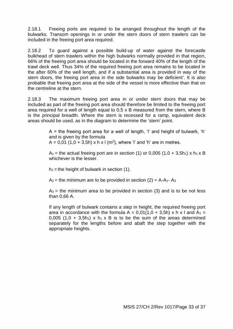
MSIS 27/CH 2/Rev 1017/Page 33 of 37
2.18.1 Freeing ports are required to be arranged throughout the length of the bulwarks. Transom openings in or under the stern doors of stern trawlers can be included in the freeing port area required. 2.18.2 To guard against a possible build-up of water against the forecastle bulkhead of stern trawlers within the high bulwarks normally provided in that region, 66% of the freeing port area should be located in the forward 40% of the length of the trawl deck well. Thus 34% of the required freeing port area remains to be located in the after 60% of the well length, and if a substantial area is provided in way of the stern doors, the freeing port area in the side bulwarks may be deficient'. It is also probable that freeing port area at the side of the vessel is more effective than that on the centreline at the stern. 2.18.3 The maximum freeing port area in or under stern doors that may be included as part of the freeing port area should therefore be limited to the freeing port area required for a well of length equal to 0,5 x B measured from the stern, where B is the principal breadth. Where the stern is recessed for a ramp, equivalent deck areas should be used, as in the diagram to determine the ‘stern’ point.
A = the freeing port area for a well of length, ‘l’ and height of bulwark, ‘h’ and is given by the formula A = 0,01 (1,0 + 3,5h) x h x l (m2), where ‘l’ and ‘h’ are in metres. A1 = the actual freeing port are in section (1) or 0,005 (1,0 + 3,5h1) x h1 x B
whichever is the lesser. h1 = the height of bulwark in section (1). A2 = the minimum are to be provided in section (2) = A-A1- A3 A3 = the minimum area to be provided in section (3) and is to be not less than 0,66 A. If any length of bulwark contains a step in height, the required freeing port area in accordance with the formula A = 0,01(1,0 + 3,5h) x h x l and A1 = 0,005 (1,0 + 3,5h1) x h1 x B is to be the sum of the areas determined separately for the lengths before and abaft the step together with the appropriate heights.

MSIS 27/CH 2/Rev 1017/Page 34 of 37
2.19 Check calculation - Buoyancy for water on deck
2.19.1 A check calculation can be carried out should it be suspected that the reserve intact buoyancy of the vessel, when operating at its deepest operating waterline, is less than the volume of water that may be trapped by upper deck bulwarks and deck houses. The reserve intact buoyancy of the vessel is the sum of the under deck buoyancy (calculated from the waterline to the top of the weather deck) plus that part of any intact deck house or erection that contributes buoyancy up to a level corresponding to their lowest coaming or sill height. 2.19.2 The vessel should be assumed upright with water filling any wells up to the lowest overspill point at the top of the bulwarks. Intact deck erections may be considered to contribute buoyancy up to a level corresponding with the top of sill of the lowest access door, hatch or vent opening that leads to such erections. 2.19.3 If, as a result of the above buoyancy check, the vessel is found to be deficient in reserves of buoyancy, the required freeing port areas should be increased to ensure that any water on deck may be rapidly and effectively cleared. Additionally the heights of sills to hatchways and weathertight doors may be required to be increased in proportion to the deficiency. 2.19.4 Any vessel found to be significantly deficient in reserves of buoyancy should undergo an in depth examination that covers both the vessel’s arrangements for clearing water and its reserves of stability. Limitations on the vessel’s maximum operating draught may require to be imposed for vessels with high bulwarks. 2.20 Check calculation – Water on deck 2.20.1 Water on deck calculations should be carried out in accordance with para3.1.2.7 of the Over 24m Code. 2.21 Check calculation - Freeing of entrapped water 2.21.1 The freeing ports should allow the rapid clearing of water from the deck. If the freeing port area calculated using the applicable formulae is considered inadequate for any reason the following check could be used to establish the effectiveness of the freeing ports. The amount of entrapped water should ideally be
Intact erections on deck that contribute to reserve buoyancy (effective up to the erection’s lowest sill height only).
Water on deck to top of bulwark
Underdeck reserve buoyancy
Weather deck
Bulwark top
Deepest operating waterline
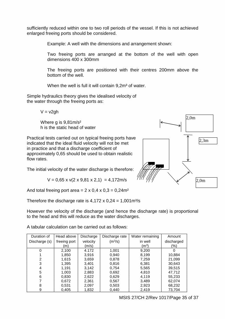
MSIS 27/CH 2/Rev 1017/Page 35 of 37
sufficiently reduced within one to two roll periods of the vessel. If this is not achieved enlarged freeing ports should be considered.
Example: A well with the dimensions and arrangement shown: Two freeing ports are arranged at the bottom of the well with open dimensions 400 x 300mm The freeing ports are positioned with their centres 200mm above the bottom of the well. When the well is full it will contain 9,2m³ of water.
Simple hydraulics theory gives the idealised velocity of the water through the freeing ports as:
V = v2gh
Where g is 9,81m/s² h is the static head of water
Practical tests carried out on typical freeing ports have indicated that the ideal fluid velocity will not be met in practice and that a discharge coefficient of approximately 0,65 should be used to obtain realistic flow rates. The initial velocity of the water discharge is therefore: V = 0,65 x v(2 x 9,81 x 2,1) = 4,172m/s And total freeing port area = 2 x 0,4 x 0,3 = 0,24m² Therefore the discharge rate is 4,172 x 0,24 = 1,001m³/s However the velocity of the discharge (and hence the discharge rate) is proportional to the head and this will reduce as the water discharges. A tabular calculation can be carried out as follows:
Duration of Head above Discharge Discharge rate Water remaining Amount
Discharge (s) freeing port (m)
velocity (m/s)
(m3/s) in well (m3)
discharged (%)
0 2,100 4.172 1,001 9,200 0 1 1,850 3,916 0,940 8,199 10,884 2 1,615 3,659 0,878 7,259 21,099 3 1,395 3,401 0,816 6,381 30,643 4 1,191 3,142 0,754 5,565 39,515 5 1,003 2,883 0,692 4,810 47,712 6 0,830 2,622 0,629 4,119 55,233 7 0,672 2,361 0,567 3,489 62,074 8 0,531 2,097 0,503 2,923 68,232 9 0,405 1,832 0,440 2,419 73,704
2,3m
2,0m
2,0m

MSIS 27/CH 2/Rev 1017/Page 36 of 37
2.22 Water freeing from shelters 2.22.1 When a weathertight shelter is fitted, surveyors should ensure that the shelter remains intact at all times such as to provide the assumed contribution to the stability of the vessel and also to prevent the accidental influx of water into the shelter with consequential danger due to listing, free surface and extension of flooding. 2.22.2 Difficulties have arisen on some vessels fitted with such shelters in regard to disposal of trash and wash water and this had led in several instances to holes being cut in the shelter sides. Apart from the threat to safety such practices may result the vessels certification becoming invalid. Surveyors should consult with owners prior to any significant modification. 2.22.3 Various acceptable means of disposal are available, e.g. by internal drainage using trash pump, bulwark level chute with flap valve and upper closure, etc or through aft end of house. 2.22.4 Waste-chutes and similar discharges installed in enclosed spaces on the working deck should be of robust construction and be provided with; (i) an automatic valve with accessible local means of closure, and where only 1,2m above the highest waterline, a remote means of closure from outside the space, with wheelhouse visual indication, should also be fitted, and (ii) an easily accessible, hinged, gasketed and clamped steel cover should be fitted. 2.22.5 In addition openings at deck level may be fitted provided detailed arrangements comply with the following: New vessels;
(a) an automatic non-return valve should be fitted at the shell. Valve to be
balanced and capable of remaining closed at 15o heel. In order to fulfil the required functions, the fitting should be similar to a storm valve, i.e. with flap hinged at upper edge such that the angle of the seat and weight of the flap ensures that the valve remains closed until 15o heel preferrably without need for external balance weights, and provides positive non-return operation (commonly referred to as a tonnage valve). The valve should be of steel, bronze or other ductile material and of substantial construction having regard to its function as part of the weathertight superstructure;
(b) the gross size of opening should not exceed 250mm x 150mm; (c) the bottom of the opening in way of the valve should not be submerged
in still water in any anticpated condition of loading at an angle of heel less than 10º;
(d) the operating spindle should not be less than 600mm above the deck.
Positive means of securing the valve in the closed position should be fitted in association with the extended spindle;

MSIS 27/CH 2/Rev 1017/Page 37 of 37
(e) a notice to be provided above the valve indicating that it should be kept
securely closed except when in use. Similar reference should be made in the Stability Booklet;
(f) only one valve on each side of vessel may be fitted; and (g) where vessel also operates in bulk fishing mode and (c) cannot be met,
a watertight bolted plate or hinged cover at inboard and of valve should be provided as additional closure in this mode. Attention should be drawn in notice at (e) and reference made in the Stability Booklet.
2.22.6 For major conversions, lengthening, etc - the requirements for new vessels should be applied unless proved impracticable when the requirements below should be considered. 2.22.7 Existing vessels with weathertight shelters fitted to satisfy stability requirements should, in principle, comply with requirements for new vessels unless proved impracticable to comply with para (c), when the following would be considered;
(a) para(a), (d)-(g), for new vessels, to apply; (b) the gross size of opening should not exceed 250mm x 75mm; (c) the minimum freeboard in way of the valve measured from the bottom
of the valve opening in the worst anticipated condition of loading should not be less than 150mm.
(d) valves would not be permitted in vessels unable to meet para (c).
Internal disposal using trash pump or alternative means would be required.
2.22.8 In general non-corrodible hinge pins, bearings, etc should be incorporated in the fittings required in these closing arrangements. 2.22.9 Acceptance of valves under the arrangements described above does not exempt a vessel from complying with paragraph 4.3 of the 15-24m Code or paragraph 4.4 of the over 24m Code, as applicable.