209R-92 Prediction of Creep, Shrinkage, and Temperature · PDF fileACI 209R-92 (Reapproved...
47
ACI 209R-92 (Reapproved 1997) Prediction of Creep, Shrinkage, and Temperature Effects in Concrete Structures Reported by ACI Committee 209 James A. Rhodes? Domingo J. Carreira++ Chairman, Committee 209 Chairman, Subcommittee II James J. Beaudoin Dan E. Brauson*t Bruce R. Gamble H.G. Geymayer Brij B. Goyalt Brian B. Hope John R. Keeton t Clyde E. Kesler William R. Lorman Jack A. Means? Bernard L Meyers l - R.H. Mills K.W. Nasser A.M. Neville Frederic Roll? John Timus k Michael A. Ward Corresponding Members: John W. Dougill, H.K. Hilsdorf Committee members voting on the 1992 revisions: Marwan A. Daye Chairman Akthem Al-Manaseer James J. Beaudoiu Dan E. Branson Domingo J. Carreira Jenn-Chuan Chem Menashi D. Cohen Robert L Day Chung C. Fu 1 Satyendra K. Ghosh Brij B. Goyal Will Hansen Stacy K. Hirata Joe Huterer Hesham Marzouk Bernard L. Meyers Karim W. Nasser Mikael PJ. Olsen Baldev R. Seth Kwok-Nam Shiu Liiia Panula$ * Member of Subcommittee II, which prepared this report t Member of Subcommittee II S=-=d This report reviews the methods for predicting creep, shrinkage and temper ature effects in concrete structures. It presents the designer with a unified and digested approach to the problem of volume changes in concrete. The individual chapters have been written in such a way that they can be used almost independently from the rest of the report. The report is generally consistent with ACI 318 and includes material indicated in the Code, but not specifically defined therein. Keywords: beams (supports); buckling; camber; composite construction (concrete to concrete); compressive strength; concretes; concrete slabs; cracking (frac turing); creep properties; curing; deflection; flat concrete plates; flexural strength; girders; lightweight-aggregate concretes; modulus of elasticity; moments of inertia; precast concrete; prestressed concrete: prestress loss; reinforced concrete: shoring; shrinkage; strains; stress relaxation; structural design; temperature; thermal expansion; two-way slabs: volume change; warpage. ACI Committee Reports, Guides, Standard Practices, and Commentaries are intended for guidance in designing, plan- ning, executing, or inspecting construction and in preparing specifications. References to these documents shall not be made in the Project Documents. If items found in these documents are desired to be a part of the Project Docu- ments, they should be phrased in mandatory language and incorporated into the Project Documents. J CONTENTS Chapter 1--General, pg. 209R-2 l.l-Scope 1.2-Nature of the problem 1.3 -Definitions of terms Chapter 2-Material response, pg. 209R-4 2.1 -Introduction 2.2-Strength and elastic properties 2.3-Theory for predicting creep and shrinkage of con- crete 2.4-Recommended creep and shrinkage equations for standard conditions The 1992 revisions became effective Mar. 1, 1992. The revisions consisted of minor editorial changes and typographical corrections. Copyright 8 1982 American Concrete Institute. All rights reserved including rights of reproduction and use in any form or by any means, including the making of copies by any photo process, or by any elec- tronic or mechanical device, printed or written or oral, or recording for sound or visual reproduction or for use in any knowledge or retrieval system or device, unless permission in writing is obtained from the copyright proprietors.
Transcript of 209R-92 Prediction of Creep, Shrinkage, and Temperature · PDF fileACI 209R-92 (Reapproved...

ACI 209R-92(Reapproved 1997)
Prediction of Creep, Shrinkage, and Temperature Effects in
Concrete Structures
Reported by ACI Committee 209James A. Rhodes? Domingo J. Carreira++
Chairman, Committee 209 Chairman, Subcommittee II
James J. BeaudoinDan E. Brauson*tBruce R. GambleH.G. GeymayerBrij B. GoyaltBrian B. Hope
John R. Keeton tClyde E. KeslerWilliam R. LormanJack A. Means?Bernard L Meyers l -R.H. Mills
K.W. NasserA.M. NevilleFrederic Roll?John Timus kMichael A. Ward
Corresponding Members: John W. Dougill, H.K. Hilsdorf
Committee members voting on the 1992 revisions:
Marwan A. DayeChairman
Akthem Al-ManaseerJames J. BeaudoiuDan E. BransonDomingo J. CarreiraJenn-Chuan ChemMenashi D. CohenRobert L Day
Chung C. Fu 1Satyendra K. GhoshBrij B. GoyalWill HansenStacy K. HirataJoe HutererHesham Marzouk
Bernard L. MeyersKarim W. NasserMikael PJ. OlsenBaldev R. SethKwok-Nam ShiuLiiia Panula$
* Member of Subcommittee II, which prepared this reportt Member of Subcommittee IIS=-=d
This report reviews the methods for predicting creep, shrinkage and temperature effects in concrete structures. It presents the designer with a unifiedand digested approach to the problem of volume changes in concrete. Theindividual chapters have been written in such a way that they can be usedalmost independently from the rest of the report.The report is generally consistent with ACI 318 and includes materialindicated in the Code, but not specifically defined therein.
Keywords: beams (supports); buckling; camber; composite construction (concreteto concrete); compressive strength; concretes; concrete slabs; cracking (fracturing); creep properties; curing; deflection; flat concrete plates; flexural strength;girders; lightweight-aggregate concretes; modulus of elasticity; moments of inertia;precast concrete; prestressed concrete: prestress loss; reinforced concrete: shoring;shrinkage; strains; stress relaxation; structural design; temperature; thermalexpansion; two-way slabs: volume change; warpage.
ACI Committee Reports, Guides, Standard Practices, andCommentaries are intended for guidance in designing, plan-ning, executing, or inspecting construction and in preparingspecifications. References to these documents shall not bemade in the Project Documents. If items found in thesedocuments are desired to be a part of the Project Docu-ments, they should be phrased in mandatory language andincorporated into the Project Documents.
J
CONTENTS
Chapter 1--General, pg. 209R-2l . l -Scope1.2-Nature of the problem1.3 -Definitions of terms
Chapter 2-Material response, pg. 209R-42.1 -Introduction2.2-Strength and elastic properties2.3-Theory for predicting creep and shrinkage of con-
crete2.4-Recommended creep and shrinkage equations
for standard conditions
The 1992 revisions became effective Mar. 1, 1992. The revisions consisted ofminor editorial changes and typographical corrections.
Copyright 8 1982 American Concrete Institute.All rights reserved including rights of reproduction and use in any form or by
any means, including the making of copies by any photo process, or by any elec-tronic or mechanical device, printed or written or oral, or recording for sound orvisual reproduction or for use in any knowledge or retrieval system or device,unless permission in writing is obtained from the copyright proprietors.

209R-2 ACI COMMITTEE REPORT
2.5-Correction factors for conditions other than thestandard concrete composition
2.6-Correction factors for concrete composition2.7-Example2.8-Other methods for prediction of creep and
shrinkage2.9-Thermal expansion coefficient of concrete2.10-Standards cited in this report
Chapter 3-Factors affeating the structural response -assumptions and methods of analysis, pg. 209R-12
3.1-Introduction3.2-Principal facts and assumptions3.3-Simplified methods of creep analysis3.4-Effect of cracking in reinforced and prestressed
members3.5-Effective compression steel in flexural members3.6-Deflections due to warping3.7-Interdependency between steel relaxation, creep
and shrinkage of concrete
Chapter 4-Response of structures in which time -change of stresses due to creep, shrinkage and tem-perature is negligible, pg. 209R-16
4.1-Introduction4.2-Deflections of reinforced concrete beam and slab4.3-Deflection of composite precast reinforced beams
in shored and unshored constructions4.4-Loss of prestress and camber in noncomposite
prestressed beams4.5-Loss of prestress and camber of composite pre-
cast and prestressed-beams unshored and shoredconstructions
4.6-Example4.7-Deflection of reinforced concrete flat plates and
two-way slabs4.8-Time-dependent shear deflection of reinforced
concrete beams4.9-Comparison of measured and computed deflec-
tions, cambers and prestress losses using pro-cedures in this chapter
Chapter 5-Response of structures with signigicant timechange of stress, pg. 209R-22
5.l-Scope5.2-Concrete aging and the age-adjusted effective
modulus method5.3-Stress relaxation after a sudden imposed defor-
mation5.4-Stress relaxation after a slowly-imposed defor-
mation5.5-Effect of a change in statical system5.6-Creep buckling deflections of an eccentrically
compressed member5.7-Two cantilevers of unequal age connected at time
t by a hinge 5.8 loss of compression in slab anddeflection of a steel-concrete composite beam
5.9-Other cases5.10-Example
Acknowledgements, pg. 209R-25
References, pg. 209R-25
Notation, pg. 209R-29
Tables, pg. 209R-32
CHAPTER l-GENERAL
l. l-ScopeThis report presents a unified approach to predicting
the effect of moisture changes, sustained loading, andtemperature on reinforced and prestressed concretestructures. Material response, factors affecting the struc-tural response, and the response of structures in whichthe time change of stress is either negligible or significantare discussed.
Simplified methods are used to predict the materialresponse and to analyze the structural response underservice conditions. While these methods yield reasonablygood results, a close correlation between the predicteddeflections, cambers, prestress losses, etc., and themeasurements from field structures should not be ex-pected. The degree of correlation can be improved if theprediction of the material response is based on test datafor the actual materials used, under environmental andloading conditions similar to those expected in the fieldstructures.
These direct solution methods predict the response be-havior at an arbitrary time step with a computational ef-fort corresponding to that of an elastic solution. Theyhave been reasonably well substantiated for laboratoryconditions and are intended for structures designed usingthe ACI 318 Code. They are not intended for the analy-sis of creep recovery due to unloading, and they applyprimarily to an isothermal and relatively uniform en-vironment .
Special structures, such as nuclear reactor vessels andcontainments, bridges or shells of record spans, or largeocean structures, may require further considerationswhich are not within the scope of this report. For struc-tures in which considerable extrapolation of the state-of-the-art in design and construction techniques is achieved,long-term tests on models may be essential to provide asound basis for analyzing serviceability response. Refer-ence 109 describes models and modeling techniques ofconcrete structures. For mass-produced concrete mem-bers, actual size tests and service inspection data willresult in more accurate predictions. In every case, usingtest data to supplement the procedures in this report willresult in an improved prediction of service performance.

PREDICTION OF CREEP 209R-3
1.2-Nature of the problemSimplified methods for analyzing service performance
are justified because the prediction and control of time-dependent deformations and their effects on concretestructures are exceedingly complex when compared withthe methods for analysis and design of strength perfor-mance. Methods for predicting service performance in-volve a relatively large number of significant factors thatare difficult to accurately evaluate. Factors such as thenonhomogeneous nature of concrete properties caused bythe stages of construction, the histories of water content,temperature and loading on the structure and their effecton the material response are difficult to quantify even forstructures that have been in service for years.
The problem is essentially a statistical one becausemost of the contributing factors and actual results are in-herently random variables with coefficients of variationsof the order of 15 to 20 percent at best. However, as inthe case of strength analysis and design, the methods forpredicting serviceability are primarily deterministic innature. In some cases, and in spite of the simplifyingassumptions, lengthy procedures are required to accountfor the most pertinent factors.
According to a survey by ACI Committee 209, mostdesigners would be willing to check the deformations oftheir structures if a satisfactory correlation between com-puted results and the behavior of actual structures couldbe shown. Such correlations have been established forlaboratory structures, but not for actual structures. Sinceconcrete characteristics are strongly dependent on en-vironmental conditions, load history, etc., a poorer cor-relation is normally found between laboratory and fieldservice performances than between laboratory and fieldstrength performances.
With the above limitations in mind, systematic designprocedures are presented which lend themselves to acomputer solution by providing continuous time functionsfor predicting the initial and time-dependent averageresponse (including ultimate values in time) of structuralmembers of different weight concretes.
The procedures in this report for predicting time-dependent material response and structural service per-formance represent a simplified approach for designpurposes. They are not definitive or based on statisticalresults by any means. Probabilisitic methods are neededto accurately estimate the variability of all factors in-volved.
1.3-Definitions of termsThe following terms are defined for general use in this
report. It should be noted that separability of creep andshrinkage is considered to be strictly a matter of defin-ition and convenience. The time-dependent deformationsof concrete, either under load or in an unloaded speci-men, should be considered as two aspects of a singlecomplex physical phenomenon. 88
1.3.1 ShrinkageShrinkage, after hardening of concrete, is the decrease
with time of concrete volume. The decrease is clue tochanges in the moisture content of the concrete andphysico-chemical changes, which occur without stress at-tributable to actions external to the concrete. The con-verse of shrinkage is swellage which denotes volumetricincrease due to moisture gain in the hardened concrete.Shrinkage is conveniently expressed as a dimensionlessstrain (in./in. or m/m) under steady conditions of relativehumidity and temperature.
The above definition includes drying shrinkage, auto-genous shrinkage, and carbonation shrinkage.
a) Drying shrinkage is due to moisture loss in theconcrete
b) Autogenous shrinkage is caused by the hydrationof cement
c) Carbonation shrinkage results as the variouscement hydration products are carbonated in thepresence of CO,
Recommended values in Chapter 2 for shrinkagestrain (E& are consistent with the above definitions.
1.3.2 CreepThe time-dependent increase of strain in hardened
concrete subjected to sustained stress is defined as creep.It is obtained by subtracting from the total measuredstrain in a loaded specimen, the sum of the initial in-stantaneous (usually considered elastic) strain due to thesustained stress, the shrinkage, and the eventual thermalstrain in an identical load-free specimen which is sub-jected to the same history of relative humidity and tem-perature conditions. Creep is conveniently designated ata constant stress under conditions of steady relativehumidity and temperature, assuming the strain at loading(nominal elastic strain) as the instantaneous strain at anytime.
The above definition treats the initial instantaneousstrain, the creep strain, and the shrinkage as additive,even though they affect each other. An instantaneouschange in stress is most likely to produce both elastic andinelastic instantaneous changes in strain, as well as short-time creep strains (10 to 100 minutes of duration) whichare conventionally included in the so-called instantaneousstrain. Much controversy about the best form of “prac-tical creep equations” stems from the fact that no clearseparation exists between the instantaneous strain (elasticand inelastic strains) and the creep strain. Also, the creepdefinition lumps together the basic creep and the dryingcreep.
a) Basic creep occurs under conditions of nomoisture movement to or from the environment
b) Drying creep is the additional creep caused bydrying
In considering the effects of creep, the use of either aunit strain, 6, (creep per unit stress), or creep coefficient,vt (ratio of creep strain to initial strain), yields the same

209R-4 ACI COMMITTEE REPORT
on
results, since the concrete initial modulus of elasticity,Eli, must be included, that is:
V* = S*E,i
This is seen from the relations:
(1-1)
Creep strain = Q S,=E Ei vt, a n d
J%i = u,ei
where, u is the applied constant stress and ei is the in-stantaneous strain.
The choice of either of S, or vt is a matter of con-venience depending on whether it is desired to apply thecreep factor to stress or strain. The use of v, is usually*more convenient for calculation of deflections and pre--stressing losses.
1.3.3 Relaxation c
Relaxation is the gradual reduction of stress with timeunder sustained strain. A sustained strain produces aninitial stress at time of application and a deferred neg-ative (deductive)decreasing rate.89
stress increasing with time at a
1.3.4 Modulus of elasticityThe static modulus of elasticity (secant modulus) is the
linearized instantaneous (1 to 5 minutes) stress-strainrelationship. It is determined as the slope of the secantdrawn from the origin to a point corresponding to 0.45f,’ on the stress-strain curve, or as in A STM C 469.
1.3.5 Contraction and expansionConcrete contraction or expansion is the algebraic sum
of volume changes occurring as the result of thermal var-iations caused by heat of hydration of cement and byambient temperature change. The net volume change isa function of the constituents in the concrete.
CHAPTER 2-MATERIAL RESPONSE
2.1-IntroductionThe procedures used to predict the effects of time-
dependent concrete volume changes in Chapters 3,4, and5 depend on the prediction of the material responseparameters; i.e., strength, elastic modulus, creep, shrink-age and coefficient of thermal expansion.The equations recommended in this chapter are sim-plified expressions representing average laboratory dataobtained under steady environmental and loading con-ditions. They may be used if specific material responseparameters are not available for local materials andenvironmental conditions.
Experimental determination of the response para-meters using the standard referenced throughout thisreport and listed in Section 2.10 is recommended if an accurate prediction of structural service response is desired. No prediction method can yield better resultsthan testing actual materials under environmental and
loading conditions similar to those expected in the field.It is difficult to test for most of the variables involved inone specific structure. Therefore, data from standard testconditions used in connection with the equations recom-mended in this chapter may be used to obtain a moreaccurate prediction of the material response in thestructure than the one given by the parameters recom-mended in this chapter.
Occasionally, it is more desirable to use materialparameters corresponding to a given probability or to useupper and lower bound parameters based on the expect-ed loading and envionmental conditions. This predictionwill provide a range of expected variations in the re-sponse rather than an average response. However, prob-abilistic methods are not within the scope of this report.
The importance of considering appropriate water con- tent, temperature. and loading histories in predictingcrete response parameters cannot be overemphasized.The differences between field measurements and the pre- dicted deformations or stresses are mostly due to the lackof correlation between the assumed and the actual his-tories for water content, temperature, and loading.
2.2-Strength and elastic properties2.2.1 Concrete compressive strength versus timeA study of concrete strength versus time for the data
of References 1-6 indicates an appropriate general equa-tion in the form of E . (2-l) for predicting compressivestrength at any time.64 -=-” **
KY = & u”,‘)28 (2-1)
where g in days and ~3 are constants, &‘)z8 = 28-daystrength and t in days is the age of concrete.
Compressive strength is determined in accordance withASTM C 39 from 6 x 12 in. (152 x 305 mm) standard cyl-indrical specimens, made and cured in accordance withASTM C 192.
Equation (2-1) can be transformed into
K>* = (2-2)
where a/$? is age of concrete in days at which one half ofthe ultimate (in time) compressive strength of concrete,df,‘), is reached.g2
T h e ranges of g andp in Eqs. (2-l) and (2-2) for thenormal weight, sand lightweight, and all lighweight con-cretes (using both moist and steam curing, and Types Iand III cement) given in References 6 and 7 (some 88specimens) are: a = 0.05 to 9.25, fi = 0.67 to 0.98.
The constants a andfl are functions of both the typeof cement used and the type of curing employed. The useof normal weight, sand lighweight, or all-lightweight
egate does not appear to affect these constantssignificantly. Typical values recommended in References7 are given in Table 2.2.1. Values for the time-ratio,~~‘)*f~~‘)~~ or ~~I)~/~=‘),/~~‘~~ in Eqs. (2-l) and (2-2) aregiven also in Table 2.2.1.

PREDICTION OF CREEP 209R-5
"Moist cured conditions" refer to those in ASTM C132 and C 511. Temperatures other than 73.4 f 3 F (23f 1.7 C) and relative humidities less than 35 percent mayresult in values different than those predicted when usingthe constant on Table 2.2.1 for moist curing. T h e effectof concrete temperature on the compressive and flexuralstrength development of normal weight concr etes madewith different types of cement with and withoutaccelerating admixtures at various temperatures between25 F (-3.9 C)}and 120 F (48.9 ( C) were studied in Ref-erence 90.Constants in Table 2.2.1 are not applicable to con-cretes, such as mass concrete, containing Type II or TypeV cements or containing blends of portland cement andpozzolanic materials. In those cases, strength gains areslower and may continue over periods well beyond oneyear age.
“Steam cured” means curing with saturated steam atatmospheric pressure at temperatures below 212 F (100C) .
Experimental data from References 1-6 are comparedin Reference 7 and all these data fall within about 20percent of the average values given by Eqs. (2-l) and(2-2) for cons tan t s n and /? in Table 2.2.1. The tem-perature and cycle employed in steam curing may sub-stantially affect the strength-time ratio in the early daysfollowing curing.1*7
2.2.2 Modulus of rupture, direct tensile strength andmodulus of elasticity
Eqs. (2-3), (2-4),and (2-5) are considered satisfactoryin most cases for computing average values for modulusof rupture, f,, direct tensile strength, ft’, and secant mod-ulus of elasticity at 0.4(f,‘),, E,, respectively of differentweight concretes.1~4-12
f, = & MfJ,l” (2-3)
fi’ = gt MfN” (2-4)
E,, = &t ~w30c,‘M” (2-5)
For the unit weight of concrete, w in pcf and the com-pressive strength, (fc’)t in psi
gr = 0.60 to 1.00 (a conservative value of g,. = 0.60may be used, although a value g, = 0.60 to0.70 is more realistic in most cases)
gt = ‘/3&t = 33
For w in Kg/m3 and (fc’)f in MPa
& = 0.012 to 0.021 (a conservative value of gr =0.012 may be used, although a value of g, =0.013 to 0.014 is more realistic in most cases)
& = 0.0069gct = 0.043
The modulus of rupture depends on the shape of thetension zone and loading conditions E q . (2-3) corres-ponds to a 6 x 6 in. (150 x 150 mm) cross section as inASTM C 78, Where much o f the tension zone is remotef r o m the neutral axis as in the c a s e of large box girdersor large I-beams, the modulus of rupture approaches thedirect tensile strength.
Eq. (2-5) was developed by Puuw” and is used in Sub-section 8.5.1 of Reference 27. The static modulus of e-lasticity is determined experimentally in accordance withA S T M C 649.
The modulus of elasticity of concrete, as commonlyunderstood is not the truly instantaneous modulus, buta modulus which corresponds to loads of one to fiveminutes duratiavl.86
The principal variables that affect creep and shrinkageare discussed in detail in References 3, 6, 13-16, and aresummarized in Table 2.2.2. The design approach pre-
sent&*’ for predicting creep and shrinkage: refers to``standard conditions”and correction factors for otherthan Standard conditions. This approach has also beenused in References 3, 7, 17, and 83.Based largely on information from References 3-6, 13,15, 18-21, the following general procedure is suggestedfor predicting creep and shrinkage of concrete at anytime.7
tJrvt= d+p”U (2-6)
(2-7)
where d and f (in days), @ and a are considered con-stants for a given member shape and size which definethe time-ratio part, v,, is the ultimate creep coefficientdefined as ratio of creep strain to initial strain, (es& isthe ultimate shrinkage strain, and t is the time afterloading in Eq. (2-6) and time from the end of the initialcuring in Eq. (2-7).
When @ and QI are equal to 1.0, these equations arethe familiar hyperbolic equations of Ross” and Lorman2’in slightly different form.
The form of these equations is thought to be conven-ient for design purposes, in which the concept of theultimate (in time) value is modified by the time-ratio toyield the desired result. The increase in creep after, say,100 to 200 days is usually more pronounced than shrink-age. In percent of the ultimate value, shrinkage usuallyincreases more rapidly during the first few months. Ap-propriate powers of t in Eqs. (2-6) and (2-7) were foundin References 6 and 7 to be 1.0 for shrinkage (flatterhyperbolic form) and 0.60 for creep (steeper curve for

209R-6 ACI COMMlTTEE REPORT
larger values of t). This can be seen in Fig. (2-3) and(2-4) of Reference 7.
Values of q, d, vu,, a,f, and ~QJ~ can be determinedby fitting the data obtained from tests performed inaccordance to ASTM C 512.
Normal ranges of the constants in Eqs. (2-6) and (2-7)were found to be?’
@ = 0.40 to 0.80,d = 6 to 30 days,VU = 1.30 to 4.15,
f”= 0.90 to 1.10,= 20 to 130 days,
WU = 415 x 10” to 1070 x 10m6 in./in. (m/m)
These constants are based on the standard conditionsin Table 2.2.2 for the normal weight, sand lightweight,and all lightweight concretes, using both moist and steamcuring, and Types I and III cement as in References 3-6,13, 15, 18-20, 23, 24.
Eqs. (2-8), (2-9),, and (2-10) represent the averagevalues for these data. These equations were comparedwith the data (120 creep and 95 shrinkage specimens) inReference 7. The constants in the equations were deter-mined on the basis of the best fit for all data individually.The average-value curves were then determined by firstobtaining the average of the normal weight, sand light-weight, and all lightweight concrete data separately, andthen averaging these three curves. The constants v, and(E,h), recommended in References 7 and 96 were approx-imately the same as the overall numerical averages, thatis vu-6= 2.35 was recommended versus 2.36; (‘Q.J~ = 800x 10 in./in. (m/m) versus 803 x lOA for moist cured con-crete, and 730 x lOA versus 788 x 10e6 for steam curedconcrete.
The creepsurements7,18
and shrinkage data, based on 20-year mea-for normal weight concrete with an initial
time of 28 days, are roughly comparable with Eqs. (2-8)to (2-10). Some differences are to be found because ofthe different initial times, stress levels, curing conditions,and other variables.
However, subsequent work” with 479 creep datapoints and 356 shrinkage data points resulted in the sameaverage for v, = 2.35, but a new average for (EJ, =780 x 10-6 in./in. (m/m), for both moist and steam curedconcrete. It was found that no consistent distinction inthe ultimate shrinkage strain was apparent for moist andsteam cured concrete, even though different time-ratioterms and starting times were used.
The procedure using Eqs. (2-8) to (2-10) has also beenindependently evaluated and recommended in Reference60, in which a comprehensive experimental study wasmade of the various parameters and correction factorsfor different weight concrete.
No consistent variation was found between the dif-ferent weight concretes for either creep or shrinkage. Itwas noted in the development of Eq. (2-8) that moreconsistent results were found for the creep variable in the
form of the creep coefficient, vI (ratio of creep strain toinitial strain), as compared to creep strain per unit stress,S,. This is because the effect of concrete stiffness is in-cluded by means of the initial strain.
2.4-Recommended creep and shrinkage equations forstandard conditions
Equations (2-8), (2-9),, and (2-10) are recommendedfor predicting a creep coefficient and an unrestrainedshrinkage strain at any time, including ultimate values.6-7
They apply to normal weight, sand lightweight, and alllightweight concrete (using both moist and steam curing,and Types I and III cement) under the standard condi-tions summarized in Table 2.2.2.
Values of v, and CQ)~ need to be modified by thecorrection factors in Sections 2.5 and 2.6 for conditionsother than the standard conditions.
Creep coefficient, v1 for a loading age of 7 days, formoist cured concrete and for 1-3 days steam cured con-crete, is given by Eq. (2-8).
*0.60VI =
10 + tO*@ vu(2-8)
Shrinkage after age 7 days for moist cured concrete:
(2-9)
Shrinkage after age 1-3 days for steam cured concrete:
(2-10)
In Eq. (2-8), t is time in days after loading. In Eqs.(2-9) and (2-l0), t is the time after shrinkage is con-sidered, that is, after the end of the initial wet curing.
In the absence of specific creep and shrinkage data forlocal aggregates and conditions, the average values sug-gested for v, and CQ), are:
vzl = 2.35~~ a n d
kh), = 78Oy& x 10m6 in./in., (m/m)
where yc and y& represent the product of the applicablecorrection factors as defined in Sections 2.5 and 2.6 byEquations (2-12) through (2-30).
These values correspond to reasonably well shapedaggregates graded within limits of ASTM C 33. Aggre-gates affect creep and shrinkage principally because theyinfluence the total amount of cement-water paste in theconcrete.
The time-ratio part, [right-hand side except for v, and(e&)U] of Eqs. (2-8), (2-9), and (2-l0), appears to beapplicable quite generally for design purposes. Valuesfrom the standard Eqs. (2-8) to (2-10) of vt/v, and

PREDICTION OF CREEP
(Q)~/(Q)~ are shown in Table 2.4.1. Note that v is usedin Eqs. (4-11), (4-20), and (4-22), hence, svJv, = us/vufor the age of the precast beam concrete at the slabcasting.
It has also been shownU that the time-ratio part ofEqs. (2-8) and (2-10) can be used to extrapolate 28-daycreep and shrinkage data determined experimentally inaccordance with ASTM C 512, to complete time curvesup to ultimate quite well for creep, and reasonably wellfor shrinkage for a wide variety of data. It should benoticed that the time-ratio in Eqs. (2-8) to (2-10) doesnot differentiate between basic and drying creep norbetween drying autogenous and carbonation shrinkage.Also, it is independent of member shape and size,because d, f, q, and cy are considered as constant in Eqs.(2-8), (2-9), and (2-10).
The shape and size effect can be totally considered onthe time-ratio, without the need for correction factors.That is, in terms of the shrinkage-half-time rsh, as givenby Eq. (2-35) by replacing t by t/rsh in Eq. (2-9) and byO.lt/~~~ in Eq. (2-8) as shown in 2.8.1. Also by taking @= a! = 1.0 and d = f = 26.0 [exp 0.36(+)] in Eqs. (2-6)and (2-7) as in Reference 23, where v/s is the volume tosurface ratio, in inches. For v/s in mm use d = f = 26.0exp [ 1.42 x lo-* (v/s)].
References 61, 89, 92, 98 and 101 consider the effectof the shape and size on both the time-ratio (time-dependent development) and on the coefficients affectingthe ultimate (in time) value of creep and shrinkaa e.
ACI Committee 209, Subcommittee I Report’% is re-commended for a detailed review of the effects ofconcrete constituents, environment and stress on time-dependent concrete deformations.
2.5-Correction factors for conditions other than thestandard concrete composition7
All correction factors, y, are applied to ultimatevalues. However, since creep and shrinkage for anyperiod in Eqs. (2-8) through (2-10) are linear functionsof the ultimate values, the correction factors in thisprocedure may be applied to short-term creep andshrinkage as well.
Correction factors other than those for concrete com-position in Eqs. (2-11) through (2-22) may be used inconjunction with the specific creep and shrinkage datafrom a concrete tested in accordance with ASTM C 512.
2.5.1 Loading ageFor loading ages later than 7 days for moist cured
concrete and later than l-3 days for steam cured con-crete, use Eqs. (2-11) and (2-12) for the creep correctionfactors.
Creep yell = 1.25(te,)-o*1’8 for moistcured concrete (2-11)
Creep yta = 1.13 (tpJ-o*o94 for steam curedconcrete (2-12)
where t,, is the loading age in days. Representative val-ues are shown in Table 2.51. Note that in Eqs. (4-11),(4-20), and (4-22), the Creep yea correction factor mustbe used when computing the ultimate creep coefficient ofthe present beam corresponding to the age when slab iscast, vus That is:
vu.Y = v, wreep Ye,) (2-13)
2.5.2 Differential shrinkageFor shrinkage considered for other than 7 days for
moist cured concrete and other than l-3 days for steamcured concrete, determine the difference in Eqs. (2-9)and (2-10) for any period starting after this time.
That is, the shrinkage strain between 28 days and 1year, would be equal to the 7 days to 1 year shrinkageminus the 7 days to 28 days shrinkage. In this examplefor moist cured concrete, the concrete is assumed to havebeen cured for 7 days. Shrinkage ycP factor as in 2.5.3below, is applicable to Eq. (2-9) for concrete moist curedduring a period other than 7 days.
2.5.3 Initial moist curingFor shrinkage of concrete moist cured during a period
of time other than 7 days, use the Shrinkage yCp factorin Table 2.5.3. This factor can be used to estimate differ-ential shrinkage in composite beams, for example.
Linear interpolation may be used between the valuesin Table 2.5.3.
2.5.4 Ambient relative humidityFor ambient relative humidity greater than 40 percent,
use Eqs. (2-14) through26age correction factors.7,
2-16) for the creep and shrink-y**
Creep YJ = 1.27 - O.O067R, for R > 40 (2-14)
Shrinkage y1 = 1.40 - 0.0102, for 40 5 R I 80(2-15)
= 3.00 - O.O30R, for 80 > R s 100(2-16)
where Iz is relative humidity in percent. Representativevalues are shown in Table 2.5.4.
The average value suggested for R. = 40 percent is
(E,h)U = 780 x 10m6 in./in. (m/m) in both Eqs. (2-9) and(2-10). From Eq. (2-15) of Table 2.5.4, for R = 70 per-cent, @JU = 0.70(780 x 106) = 546 x 10e6 in/in. (m/m),for example. For lower than 40 percent ambient relativehumidity, values higher than 1.0 shall be used for CreepyA and Shrinkage yl.
2.5.5 Average thickness of member other than 6 in. (150mm) or volume-surface ratio other than 1.5 in. (38 mm)
The member size effects on concrete creep and shrink-age is basically two-fold. First, it influences the time-ratio(see Equations 2-6,2-7,2-8,2-9,2-10 and 2-35). Second-ly, it also affects the ultimate creep coefficient, v, andthe ultimate shrinkage strain, (‘Q),.
Two methods are offered for estimating the effect of

209R-8 ACI COMMITTEE REPORT
member size on v, and (‘,is,. The average-thicknessmethod tends to compute correction factor values thatare higher, as compared to the volume-surface ratiomethod,5g since Creep yh = Creep yVs = 1.00 for h = 6in. (150 mm) and v/s = 1.5 in. (38 mm), respectively; thatis, when h = 4v/s.
2.5.5.a Average-thickness methodThe method of treating the effect of member size in
terms of the average thickness is based on informationfrom References 3, 6, 7, 23 and 61.
For average thickness of member less than 6 in. (150mm), use the factors given in Table 2.5.5.1. These cor-
respond to the CEB6’ values for small members. Foraverage thickness of members greater than 6 in. (150mm) and up to about 12 to 15 in. (300 to 380 mm), useEqs. (2-17) to (2-18) through (2-20).During the first year after loading:
Creep yh = 1.14-0.023 h,
For ultimate values:
Creep yh = 1.10-0.017 h,
During the first year of drying:
Shrinkage yh = 1.23-0.038 h,
For ultimate values:
(2-17)
(2-18)
(2-19)
Shrinkage yh = 1.17-0.029 h, (2-20)
where h is the average thickness in inches of the part ofthe member under consideration.
During the first year after loading:
Creep yh = 1.14-0.00092 h,
For ultimate values:
Creep Yh = 1.10-0.00067 h,
During the first year after loading:
Shrinkage yh = 1.23-0.00015 h,
For ultimate values:
Shrinkage yh = 1.17-0.00114 h,
where h is in mm.
(2-17a)
(2-18a)
(2-19a)
(2-20a)
Representative values are shown in Table 2.5.5.1.2.5.5.b Volume-surface ratio method
The volume-surface ratio equations (2-21) and (2-22)were adapted from Reference 23.
Creep yvS = %[1+1.13 exp(-0.54 v/s)] (2-21)
Shrinkage yVs = 1.2 exp(-0.12 v/s) (2-22)
where v/s is the volume-surface ratio of the member ininches.
Creep yvS = %[1+1.13 exp(-0.0213 v/s)] (2-21a)
Shrinkage yvS = 1.2 exp(-0.00472 v/s) (2-22a)
where v/s in mm.Representative values are shown in Table 2.5.5.2.
However, for either method ySh should not be takenless than 0.2. Also, use ySh (‘qJu L 100 x 10” in./in.,(m/m) if concrete is under seasonal wetting and dryingcycles and Y& k/Ju 2 150 x 10m6 in./in. (m/m) if concreteis under sustained drying conditions.
2.5.6 Temperature other than 70 F (21 C)Temperature is the second major environmental factor
in creep and shrinkage. This effect is usually consideredto be less important than relative humidity since in moststructures the range of operating temperatures is sma11,68and high temperatures seldom affect the structuresduring long periods of time.
The effect of temperature changes on concrete creep6’and shrinkage is basically two-fold. First, they directlyinfluence the time ratio rate. Second, they also affect therate of aging of the concrete, i.e. the change of materialproperties due to progress of cement hydration. At 122F (50 C), creep strain is approximately two to three timesas great as at 68-75 F (19-24 C). From 122 to 212 F (50to 100 C) creep strain continues to increase with tem-perature, reaching four to six times that experienced atroom temperatures. Some studies have indicated an ap-parent creep rate maximum occurs between 122 and 176F (50 and 80 C).” There is little data establishing creeprates above 212 F (100 C). Additional information ontemperature effect on creep may be found in References68, 84, and 85.
2.6-Correction factors for concrete compositionEquations (2-23) through (2-30) are recommended for
use in obtaining correction factors for the effect ofslump, percent of fine aggregate, cement and air content.It should be noted that for slump less than 5 in. (130mm), fine aggregate percent between 40-60 percent,cement content of 470 to 750 lbs. per yd3 (279 to 445kg/m3) and air content less than 8 percent, these factorsare approximately equal to 1.0.
These correction factors shall be used only in con-nection with the average values suggested for v, = 2.35and @JU = 780 x 10m6 in./in. (m/m). As recommended in2.4, these average values for v, and &dU should be usedonly in the absence of specific creep and shrinkage datafor local aggregates and conditions determined in accord-ance with ASTM C 512.
If shrinkage is known for local aggregates and con-ditions, Eq. (2-31), as discussed in 2.6.5, is recommended.

PREDICTION OF CREEP 209R-9
-
r
The principal disadvantage of the concrete compo-sition correction factors is that concrete mix charac-teristics are unknown at the design stage and have to beestimated. Since these correction factors are normally notexcessive and tend to offset each other, in most cases,they may be neglected for design purposes.
2.6.1 Slump
Creep Ys = 0.82 + 0.067s
Shrinkage ys = 0.89 + 0.04ls
(2-23)
(2-24)
where smm use:
is the observed slump in inches. For slump in
Creep YS = 0.82 + 0.00264s (2-23 a)
Shrinkage ys = 0.89 + 0.00161s (2-24a)
2.6.2 Fine aggregate percentage
Creep Y# = 0.88 + 0.0024@ (2-25)
For @ I 50 percent
Shrinkage yg = 0.30 + 0.014q (2-26)
For @ > 50 percent
Shrinkage = 0.90 + 0.002g (2-27)
where @ is the ratio of the fine aggregate to total aggre-gate by weight expressed as percentage.
2.6.3 Cement contentCement content has a negligible effect on creep co-
efficient. An increase in cement content causes a reducedcreep strain if water content is kept constant; however,data indicate that a proportional increase in modulus ofelasticity accompanies an increase in cement content.
If cement content is increased and water-cement ratiois kept constant, slump and creep will increase and Eq.(2-23) applies also.
Shrinkage y, = 0.75 + 0.00036c (2-28)
where c is the cement contentKg/m3,
in pounds perFor cement content in use:
cubic yard.
Shrinkage y= = 0.75 + 0.00061~ (2-28a)
2.6.4 Air content
Creep ya! = 0.46 + O.O9ar,but not less than 1.0 (2-29)
Shrinkage ya = 0.95 + 0.008~~ (2-30)
where LY is the air content in percent.
2.6.5 Shrinkage ratio of concretes with equivalent pastequality91
Shrinkage strain is primarily a function of the shrink-age characteristics of the cement paste and of the ag-gregate volume concentration. If the shrinkage strain ofa given mix has been determined, the ratio of shrinkagestrain of two mixes (QJ~/(E,~$~, with different content ofpaste but with equivalent paste quality is given in Eq.(2-31).
(% )PI 1 - (vJ”3-=(% A2 1 - (v2)U3
(2-31)
where v1 and v2 are the total aggregate solid volumes perunit volume of concrete for each one of the mixes.
2.7-ExampleFind the creep coefficient and shrinkage strains at 28,
90, 180, and 365 days after the application of the load,assuming that the following information is known: 7 daysmoist cured concrete, age of loading tta = 28 days, 70percent ambient relative humidity, shrinkage consideredfrom 7 days, average thickness of member 8 in. (200mm), 2.5 in. slump (63 mm), 60 percent fine aggregate,752 lbs. of cement per yd3 (446 Kg/m3), and 7 percent aircontent.7 Also, find the differential shrinkage strain,(E,h)s for the period starting at 28 days after the appli-cation of the load, t,, = 56 days.
The applicable correction factors are summarized inTable 2.7.1. Therefore:
v, = (2.35)(0.710) = 1.67
(e& = (780 x 10-6)(0.68) = 530 x 1O-6
The results from the use of Eqs. (2-8) and (2-9) orTable 2.4.1 are shown in Table 2.7.2.
Notice that if correction factors for the concretecomposition are ignored for vt and (Q,J~, they will be 10and 4 percent smaller, respectively.
2.8-Other methods for predictions of creep and shrinkage
Other methods for prediction of creep and shrinkageare discussed in Reference 61, 68, 86, 87, 89, 93, 94, 95,97, and 98. Methods in References 97 and 98 subdividecreep strain into delayed elastic strain and plastic flow(two-component creep model). References 88, 89, 92, 99,100, 102, and 104 discuss the conceptual differences be-tween the current approaches to the formulation of thecreep laws. However, in dealing with any method, it isimportant to recall what is discussed in Sections 1.2 and2.1 of this report.
2.8.1 Remark on refined creep formulas needed fospecial structuresP3’94T95
.
The preceding formulation represents a compromisebetween accuracy and generality of application. More ac-curate formulas are possible but they are inevitably notas general.

209R-10 ACI COMMlTTEE REPORT
The time curve of creep given by Eq. (2-8) exhibits adecline of slope in log-t scale for long times. This prop-erty is correct for structures which are allowed to losetheir moisture and have cross sections which are not toomassive (6 to 12 in., 150 to 300 mm). Structures whichare insulated, or submerged in water, or are so massivethey cannot lose much of their moisture during theirlifetime, exhibit creep curves whose slope in log-t scale isnot decreasing at end, but steadily increasing. Forexample, if Eq. (2-8) were used for extrapolating short-time creep data for a nuclear reactor containment intolong times, the long-term creep values would be seriouslyunderestimated, possibly by as much as 50 percent asshown in Fig. 3 of Ref. 81.
It has been found that creep without moisture ex-change (basic creep) for any loadin
9described by Equation (2-33).86~80~83~gage tla is betterThis is called the
double power law.In Eq. (2-33) *I is a constant, and strain CF is the sum
of the instantaneous strain and creep strain caused byunit stress.
(2-33)
where l/E0 is a constant which indicates the lefthandasymptote of the creep curve when plotted in log t-scale(time t = 0 is at - 00 in this plot). The asymptotic valuel/E0 is beyond the range of validity of Eq. (2-33) andshould not be confused with elastic modulus. Suitablevalues of constants are @I = 0.97~~ and l/E0 = 0.84/E,,,being EC, the modulus of concrete which does not under-go drying. With these values, Eq. (2-33) and Eq. (2-8)give the same creep for t,, = 28 days, t = 10,000 daysand 100 percent relative humidity (m = 0.6), all othercorrection factors being taken as one.
Eq. (2-33) has further the advantage that it describesnot only the creep curves with their age dependence, butalso the age dependence of the elastic modulus EC, inabsence of drying. EC, is given by E = l/E,, for t = 0.001day, that is:
1 1 $1K = E, + K (0.001)1/8 (t&J-% (2-34)
Eq. (2-33) also yields the values of the dynamic modu-lus, which is given by c = l/Edyn when t = 10” days issubstituted. Since three constants are necessary to de-scribe the age dependence of elastic modulus (E,, @, andl/3), only one additional constant (i.e., l/s> is needed todescribe creep.
In case of drying, more accurate, but also more com-plicated, formulas may be obtainedg4 if the effect of crosssection size is expressed in terms of the shrinkage half-time, as given in Eq. (2-35) for the age td at which con-crete drying begins.
h*c Cl[ P--7sh = 6oo 150 (C,)=
where:
(2-35)
AT
T
To
W
characteristic thickness of the cross section,or twice the volume-surface ratio2 v/s in mm)
Drying diffusivity of the concrete (approx.10 mm/day if measurements are unavail-able)
age dependence coefficient
C,1,(0.05 + /iKqQ
z - 12, if C, < 7, set C, = 7if C, > 21, set C, = 21
coefficient depending on the shape of crosssection, that is:
1.00 for an infinite long slab1.15 for an infinite long cylinder1.25 for an infinite long square prism1.30 for a sphere1.55 for a cube
temperature coefficient
fexp(y -y)
concrete temperature in kelvin
reference temperature in kelvin
water content in kg/m3
By replacing t in Eq. (2-9) t/rsh, shrinkage is expressedwithout the need for the correction factor for size in Sec-tion 2.5.5.
The effect of drying on creep may then be expressedby adding two shrinkage-like functions vd and vP to thedouble power law for unit stress.g6 Function vd expressesthe additional creep during drying and function up, beingnegative, expresses the decrease of creep by loading afteran initial drying. The increase of creep during dryingarises about ten times slower than does shrinkage and sofunction vd is similar to shrinkage curve in Eq. (2-9) witht replaced by 0.1 t/Tsh in Eq. (2-8).
This automatically accounts also for the size effect,without the need for any size correction factor. The de-crease of creep rate due to drying manifests itself onlyvery late, after the end of moisture loss. This is apparentfrom the fact that function rsh is similar to shrinkagecurve in Eq. (2-9) with t replaced by 0.01 t/Tsh. Both vdand vP include multiplicative correction factors for rela-tive humidity, which are zero at 100 percent, and func-tion vd further includes a factor depending on the timelag from the beginning of drying exposure to the begin-ning of loading.
2.9-Thermal expansion coefficient of concrete
PREDICTION OF CREEP 209R-11
2.9.1 Factors affecting the expansion coefficientThe main factors affecting the value of the thermal
coefficient of a concrete are the type and amount ofaggregate and the moisture content. Other factors suchas mix proportions, cement type and age influence itsmagnitude to a lesser extent.
The thermal coefficient of expansion of concrete usu-ally reflects the weighted average of the various constitu-ents. Since the total aggregate content in hardened con-crete varies from 65 to 80 percent of its volume, and theelastic modulus of aggregate is generally five times thatof the hardened cement component, the rock expansiondominates in determining the expansion of the compositeconcrete. Hence, for normal weight concrete with asteady water content (degree of saturation), the thermalcoefficient of expansion for concrete can be regarded asdirectly proportional to that of the aggregate, modifiedto a limited extent by the higher expansion behavior ofhardened cement.
Temperature changes affect concrete water content,environment relative humidity and consequently concretecreep and shrinkage as discussed in Section 2.5.6. Ifcreep and shrinkage response to temperature changes areignored and if complete histories for concrete water con-tent, temperature and loading are not considered, theactual response to temperature changes may drasticallydiffer from the predicted one.79
2.9.2 Prediction of thermal expansion coefficientThe thermal coefficients of expansion determined
when using testing methods in ASTM C 531 and CRD 39correspond to the oven-dry condition and the saturatedconditions, respectively. Air-dried concrete has a highercoefficient than the oven-dry or saturated concrete,therefore, experimental values shall be corrected for theexpected degree of saturation of the concrete member.Values of enlc in Table 2.9.1 may be used as corrections
to the coefficients determined from saturated concretesamples. In the absence of specific data from localmaterials and environmental conditions, the values givenby Eq. (2-32) for the thermal coefficient of expansion e,hmay be used.76 Eq. (2-32) assumes that the thermal co-efficient of expansion is linear within a temperaturechange over the range of 32 to 140 F (0 to 60 C) andapplies only to a steady water content in the concrete.For e,h in 10m6/F:
eth = emc + 1.72 + 0.72 e n (2-32)
For e,h in 10v6/C:
where:
eth = emc + 3.1 + 0.72 e, (2-32a)
emC
= the degree of saturation component as givenin Table 2.9.1
1.72 = the hydrated cement past component (3.1)
e, = the average thermal coefficient of the totalaggregate as given in Table 2.9.2
If thermal expansion of the sand differs markedly fromthat of the coarse aggregate, the weighted average bysolid volume of the thermal coefficients of the sand andcoarse aggregate shall be used.
A wide variation in the thermal expansion of the ag-gregate and related concrete can occur within a rockgroup. As an illustration, Table 2.9.3 summarizes therange of measured values for each rock group in theresearch data cited in Reference 76.
For ordinary thermal stress calculations, when the typeof aggregate and concrete degree of saturation areunknown and an average thermal coefficient is desired,elh = 5.5 x 1 0m6/F (erh = 10.0 x 10m6/C) may be sufficient.However, in estimating the range of thermal movements(e.g., highways, bridges, etc.), the use of lower and upperbound values such as 4.7 x 10w6/F and 6.5 x 10e6/F (8.5 x10w6/C and 11.7 x 10v6/C) would be more appropriate.
2.10-Standards cited in this reportStandards of the American society for Testing and
Materials (ASTM) referenced in this report are listedbelow with their serial designation:
ASTM A 416
ASTM A 421
ASTM C 33
ASTM C 39
ASTM C 78
ACI C 192
ASTM C 469
ASTM C 511
ASTM C 512
ASTM C 531
“Standard Specification for UncoatedSeven-Wire Stress-Relieved Strand forPrestressed Concrete”“Standard Specification for UncoatedStress-Relieved Wire for PrestressedConcrete”“Standard Specifications for ConcreteAggregates”“Standard Test Method for CompressiveStrength of Cylindrical Concrctc Speci-mens”“Standard Test Method for FlexuralStrength of Concrete (Using SimpleBeam with Third-Point Loading)”“Standard Method of Making AndCuring Concrete Test Specimens in theLaboratory”“Standard Method for Static Modulus ofElasticity and Poisson’s Ratio of Con-crete in Compression”“Standard Specification for Moist Cabi-nets and Rooms Used in the Testing Hy-draulic Cements and Concretes”“Standard Test Method for Creep ofConcrete in Compression”“Standard Method for Securing, Prc-paring, and Testing Specimens fromHardened Lightweight Insulating Con-crete for Compressive Strength”

209R-12 ACI COMMITTEE REPORT
ASTM E 328 “Standard Recommended Practice forStress-Relaxation Tests for Materials andStructures”
The following standard of the U.S. Army Corps of En-gineers (CRD) is referred in Section 2.9 of this report:
CRD C39 “Method of Test for Coefficient ofLinear Thermal Expansion of Concrete”
CHAPTER 3-FACTORS AFFECTING THESTRUCTURAL RESPONSE-ASSUMPTIONS AND
METHODS OF ANALYSIS
3.1-IntroductionPrediction of the structural response of reinforced
concrete structures to time-dependent concrete volumechanges is complicated by:
a )
b)c)
d)e)f)
g)
The inherent nonelastic properties of the con-creteThe continuous redistribution of stressThe nonhomogeneous nature of concrete proper-ties caused by the stages of constructionThe effect of cracking on deflectionThe effect of external restraintsThe effect of the reinforcement and/or pre-stressing steelThe interaction between the above factors andtheir dependence on past histories of loadings,water content and temperature
The complexity of the problem requires some simplify-ing assumptions and reliance on empirical observations.
3.2-Principal facts and assumptions3.2.1 Principal facts
a)
b)
c)
d)
Each loading change produces a resulting defor-mation component continuous for an infiniteperiod of time7’Applied loads in homogeneous statically indeter-minate structures cause no time-dependentchange in stress and all deformations are pro-portional to creep coefficient vt as long as thesupport conditions remain unchanged7’The secondary, statically indetermined momentsdue to prestressing are affected in the sameproportion as prestressing force by time-depen-dent deformations, which is a relatively smalleffect that is usually neglectedIn a great many cases and except when instabilityis a factor, time-dependent strains due to actualloads do not significantly affect the load capacityof a member. Failure is controlled by very large
strains that develop at collapse, regardless of pre-vious loading history.71 In these cases, time-dependent strains only affect the structure ser-viceability. When instability is a factor, creep in-crement of the eccentricity in beam-columnsunder sustained load will decrease the membercapacity with time
e) Change in concrete properties with age, such aselastic, creep and shrinkage deformations, mustbe taken into account
3.2.2 Assumptions
a)
b)
c)
d)
e)
f)
g )
Concrete members including their creep, shrink-age and thermal properties, are considered ho-mogeneousCreep, shrinkage and elastic strains are mutuallyadditive and independentFor stresses less than about 40 to 50 percent ofthe concrete strength, creep strains are assumedto be approximately proportional to the sustainedstress and obey the principle of superposition ofstrain histories.70,so
However, tests in References 105 and 106have shown the nonlinearity of creep strain withstress can start at stresses as low as 30 to 35 per-cent of the concrete strength. Also, strain super-position is only a first approximation because theindividual response histories affect each other ascan be seen with recovery curves after unloadingShrinkage and thermal strains are linearlydistributed over the depth of the cross section.This assumption is acceptable for thin andmoderate sections, respectively, but may result inerror for thick sectionsThe complex dependence of strain upon the pasthistories of water content and temperature isneglected for the purpose of analyzing ordinarystructuresRestraint by reinforcement and/or prestressingsteel is accounted for in the average sense with-out considering any gradual stress transferbetween reinforcement and concreteThe creep time-ratio for various environmenthumidity conditions and various sizes and shapesof cross section are assumed to have the sameshape
Even with these simplifications, the theoretically exactanalysis of creep effects according to the assumptionsstated,66 is still relatively complicated. However, more ac-curate analysis is not really necessary in most instances,except special structures, such as nuclear reactor vessels,bridges or shells of record spans, or special ocean struc-tures. Therefore, simplified methods of analysis66,s0 arebeing used in conjunction with empirical methods to ac-count for the effects of cracking and reinforcementrestraint.

PREDICTION OF CREEP 209R-13
3.3-Simplified methods of creep analysisIn choosing the method of analysis, two kinds of cases
are distinguished.3.3.1 Cases in which the gradual time change of stress
due to creep and shrinkage is small and has little effectThis usually occurs in long-time deflection and pre-
stress loss calculations. In such cases the creep strain isaccounted for with sufficient accuracy by an elastic analy-sis in which the actual concrete modulus at the time ofinitial loading, is replaced with the so-called effectivemodulus as given by Eq. (3-l).
E, = Ecil(l + VJ (3-l)
This approach is implied in Chapter 4. To check if theassumption of small stress change is true, the stresscomputed on the basis of Eci should be compared withthe stress computed on the basis of E,.
3.3.2 Cases in which the gradual time change of stressdue to creep and shrinkage is significant
In such cases, the age-adjusted effective modulusmethod67,68,69 i s recommended as discussed in Chapter 5.
3.4-Effect of cracking in reinforced and prestressedmembers
To include the effect of cracking in the determinationof an effective moment of inertia for reinforced beamsand one-way slabs, Eq. (3-2)10P25a has been adopted bythe ACI Building Code (ACI 318).27
where Mcr is the cracking moment, Mmar denotes themaximum moment at the stage for which deflection isbeing computed, Ig is the moment of inertia of the grosssection neglecting the steel and I,, is the moment ofinertia of the cracked transformed section.
Eq. (3-2) applied only when Mntar L M,; otherwise,Ie = Ig.
Ie in Eq. (3-2) has limits of I8 and Icr, and thusprovides a transition expression between the two casesgiven in the ACI 318 Code.12,27 The moment of inertiaI, of the uncracked transformed section might be moreaccurately used instead of the moment inertia of thegross section Ireinforced mem‘6
in Eq. (3-2), especially for heavilyers and lightweight concrete members
(low E, and hence high modular ratio E,/E,i).Eq. (3-2) has also been shownB to apply in the
deflection calculations of cracked prestressed beams.For numerical analysis, in which the beam is divided
into segments or finite elements, it has been shown25 thatI, values at individual sections can be determined bymodifying Eq. (3-2). The power of 3 is changed to 4 andthe moment ratio in both terms is changed to MJM,where M is the moment at each section. Such a numeri-cal procedure was used in the development of Eq.(3-2).25
The above cracking moment is given in Eqs. (3-3) and
(3-4).
For reinforced members:
(3-3)
For noncomposite prestressed members:
W., = Fe + (FI,)IA, y, + (f,. I&y, - MD (3-4)
The cracking moment for unshored and shored com-posite prestressed beams is given in Eq. (41) and (42) ofReference 63.
Equation (3-2) refers to an average effective I for thevariable cracking along the span, or between the in-flection points of continuous beams. For continuousmembers (at one or both ends), a numerical proceduremay be needed although the use of an average of thepositive and negative moment region values from Eq.(3-2) as suggested in Section 9.5.2.4 of Reference 27should yield satisfactory results in most cases. For spanswhich have both ends continuous, an effective averagemoment of inertia lea is obtained by computing an aver-age for the end region values, Iel and Ze2 and then av-eraging that result with the positive moment region valueobtained for Eq. (3-2) as shown in Eq. (3-5).
(3-5)
In other cases, a weighted average related to thepositive and negative moments may be preferable. Forexample, the weighted averaa e moment of inertia Iewwould be given by Eq. (3-6).7 J
where, IeP is the effective moment of inertia for the posi-tive zone of the beam andP is a positive integer that maybe equal to unity for simplicity or equal to two, three orlarger for a modest increase in accuracy.
For a span with one end continuous, the (Iel + I,,)/2in Eqs. (3-5) and (3-6) shall be substituted for I for thenegative end zone.
For a flat2g
late and two way slab interior panels, it hasbeen shown that Eq. (3-2) can be used along with anaverage of the positive and negative moment regionvalues as follows:
Flat plate-both positive and negative values for thelong direction column strip.
Two way slabs-both positive and negative values forthe short direction middle strip.
The center of interior panels normally remains un-cracked in common designs of these slabs.

209R-14 ACI COMMITTEE REPORT
For the effect of repeated load cycles on crackingrange, see Reference 63.
3.5-Effective compression steel in flexural membersCompression steel in reinforced flexural members and
nontensioned steel in prestressed flexural members tendto offset the movement of the neutral axis caused bycreep. The net movement of the neutral axis is theresultant of two movements. A movement towards thetensile reinforcement (increasing the concrete com-pression zone, which results in a reduction in themoment arm). This movement is caused by the effect ofcreep plus a reduction in the compression zone due tothe progressive cracking in the tensile zone.
The second movement is produced by the increase insteel strains due to the reduction of the internal momentarm (plus the small effect, if any, of repeated live loadcycles). As cracking progresses, steel strains increasefurther and reduce the moment arm.
The reduced creep effect resulting from the movementof the neutral axis and the presence of compression steelin reinforced members &, and the inclusion of non-tensioned high strength or mild steel (as specified below)in prestressed members is given by the reduction factortr in Eqs. (3-7) and (3-9).
The approximate effect of progressive cracking undercreep loading and repeated load cycles is also included inthe factor tr. Eq. (3-8) refers to the combined creep andshrinkage effect in reinforced members.
For reinforced flexural members, creep effect only?’
fI = 0.85 - 0.45 (A,‘&, but not less than 0.40 (3-7)
For reinforced flexural members, creep and shrinkageeffect?p3’
fr = 1 - 0.60 (A,‘//$), but not less than 0.30
For prestressed flexural members:28T63
(3-8)
& = l/[l + A,‘M,] (3-9)
Approximately the same results are obtained in Eqs.(3-7), (3-8), and (3-9) as shown in Table 35.1. It is
assumed in Eq. (3-9) that the nontensioned steel and theprestressed steel are on the same side of the section cen-troid and that the eccentricities of the two steels are ap-proximately the same. See Reference 28 when the eccen-tricities are substantially different.Eqs. (3-8) and (4-3) are used in ACI 31827 with atime-dependent factor for both creep and shrinkage, rU= 2.0. As the ratio, A,‘/A,, increases, these two sets offactors approach the same value, since shrinkage warpingis negligible when the compression reinforcement is high.
The effects of creep plus shrinkage are arbitrarilylumped together in Eq. (3-8).
In Reference 74, Branson notes that Eq. (3-8), as usedin ACI 318L’ is likely to overestimate the effect of the
compression steel in restraining time-dependent deflec-tions of members with low steel percentage (e.g. slabs)and recommends the alternate Eq. (3-10).
& ?U = TJ[l + 50 p’] (3-10)
where [r rU is a long time deflection multiplier of theinitial deflection and p’ is the compressive steel ratioA,‘/M. He further suggests that a factor, 7W = 2.5 forbeams and rU = 3.0 for slabs, rather than 2.0, would giveimproved results.
The calculation of creep deflection as r, rt times theinitial deflection ai, yields the same results as that ob-tained using the “reduced or sustained modulus of elast-icity, Ect, method,” provided the initial or short-timemodular ratio, rz, (at the time of loading) and the trans-formed section properties are used. This can be seenfrom the fact that E,i used for computing the initialdeflection, is replaced by E, as given by Eq. (3-l), forcomputing the initial plus the creep deflection. Thefactor 1.0 in Eq. (3-l) corresponds to the initial de-flection. Except for the calculation of I in the sustainedmodulus method (when using or not using an increasedmodular ratio) and l,/rr in the effective section method,the two methods are the same for computing long-timedeflections, exclusive of shrinkage warping.
The reduction factor f,, for creep only (not creep andshrinkage) in Eq. (3-7) is suggested as a means of takinginto account the effect of compression steel and the off-setting effects of the neutral axis movement due to creepas shown in Figure 3 of Ref. 10. These offsetting effectsappear normally to result in a movement of the neutralaxis toward the tensile reinforcement such that:
in which lr from Eq. 3-7 is less than unity. (See Table3.5.1). Subscripts cp and i refer to the creep and initialstrains, curvatures 4, and deflections a, respectively.
The use of the long-time modular ratio, n, = n(1 +vJ, in computing the transformed section properties hasalso been shown3 1 , 3 2 to accomplish these purposes and toprovide satisfactory results in deflection calculations.
In all appropriate equations herein, vt, vu, rr, ru, arereplaced by fr vt, fr vu, <,. rt, lr ru respectively, whenthese effects are to be included.
3.6-Deflections due to warping3.6.1 Warping due to shrinkageDeflections due to warping are frequently ignored in
design calculation, when the effects of creep and warpingare arbitrarily lumped together.27 For thin members, suchas canopies and thin slabs, it may be desirable to con-sider warping effects separately.
For the case in which the reinforcement and eccen-tricity are constant along the span and the same in thepositive and negative moment regions of continuous
(3-11)

209R-15
beams, shrinkage deflections for uniform beams arecomputed by Eq. (3-12).
where & is a deflection coefficient defined in Table 4.2.1for different boundary conditions, and +Sh is the curva-ture due to shrinkage warping. For more practical cases,some satisfactory compromise can usually be made withregard to variations in steel content andfor nonuniform temperature effects.
eccentricity, and
3.6.2-Methods of computing shrinkage curvatureThree methods for computing shrinkage curvature
were compared in References 10 and 25 with e?
eri-mental data: the equivalent tensile force method,313 J637Miller’s method38 and an empirical method based onMiller’s abeams.”P
roach extended to include doubly reinforcedThe agreement between computed and mea-
sured results was reasonably good for all three of themethods.
The equivalent tensile force method (a fictitious elasticanalysis), as modified in References 10 and 25 using E,/2and the gross section properties for better results, isgiven by Eq. (3-13).
where q = (As + As’) EshEs, and eg and ‘g refer to thegross section.
Miller’s method38 assumes that the extreme fiber ofthe beam furthest from the tension steel (method refersto singly reinforced members only) shrinks the sameamount as the free shrinkage of the concrete, eSh. Fol-lowing this assumption, the curvature of the member isgiven by Eq. (3-14).
f4 -=
sh = (3-14)
where es is the steel strain due to shrinkage. Miller sug-gested empirical values of (ES/& = 0.1 for heavily rein-forced members and 0.3 for moderately reinforced mem-bers.
The empirical method represents a modification ofMiller’s method. The curvature of a member is given byEqs. (3-15) and (3-16) which are applicable to both singlyand doubly reinforced members. The steel percentage inthese equations are expressed in percent (p = 3 for 3percent steel, for example).
For (p - p') s 3.0 percent:
For (p - p’) > 3.0 percent:
4sh = %hlh (3-16)
where h is the overall thickness of the section.For singly reinforced members, p’ = 0, and Eq. (3-15)
reduces to Eq. (3-17).
(3-17)
which results in:
4sh = 0.56 (es&h, when p’ = 0.5 percent0.70 1.00.88 2.01.01 3.0
Eqs. (3-15), (3-16), and (3-17) were adapted fromMiller’s approach. For example, his method results in thefollowing expression for singly reinforced members:
4sh = 0.7 Esh/d for “moderately” reinforced beams
4sh’ = 0.9 Esh/d for “heavily” reinforced beams
which approximately correspond to p = 1.0 and p = 2.0in Eq. 3-17.
The use of the more convenient thickness, h, insteadof the effective depth, d, in Eqs. (3-15), (3-16), and (3-17) was found to provide closer agreement with the testdata.
3.6.3 Warping due to temperature changeSince concrete and steel reinforcement have similar
thermal coefficients of expansion (i.e., 4.7 to 6.5 x 10d/Ffor concrete and 6.5 x 10⁶/F for steel), the stresses pro-duced by normal temperature range are usually negli-gible.
When the temperature change is constant along withthe span, thermal deflections for uniform beams aregiven by Eq. (3-18).
aT = &#$&e2 (3-18)
where & is the deflection coefficient (Table 4.2.1). Thecurvature & due to temperature warping is given by Eq.(3-19).
4 rh = ce,ll th)lh (3-19)
where e,h is the thermal coefficient of expansion and fh is
the difference in temperature across the overall thicknessh.
The values of v,, Esh) and e& Usually correspond tosteady state conditions. A sustained nonuniform changein temperature will influence creep and shrinkage. As aresult, significant redistribution of stresses in staticallyindeterminate structures may occur to such an extent thatthe thermal effects caused by heating may be completelynullified. A nonuniform temperature reversal may causea stress reversal.79

209R-16 ACI COMMITTEE REPORT
3.7-Interdependency between steel relaxation, creep andshrinkage of concrete
The loss of stress in a wire or strand that occurs atconstant strain is the intrinsic relaxation &J,. Stress lossdue to steel relaxation as shown in Table 3.7.1 and as
supplied by the steel manufacturers (ASTM designationsA 416, A 421, and E 328) are examples of the intrinsicrelaxation. In actual prestressed concrete members, aconstant strain condition does not exist and the use ofthe intrinsic relaxation loss will result in an overest-imation of the relaxation loss. The use of (‘&jr and cf,),,as in Table 4.4.1.3, is a good approximation for most de- sign calculations because of the approximate nature ofcreep and shrinkage calculations. In Reference 78, arelaxation reduction factor, @, is recommended to ac-count for conditions different than the constant strain.Values of @ in Table 3.7.2 are entered by the&‘fm ratioand the parameter 2, given in Eq. (3-20).2, = (nJ,floo - Cfs,)flfsi (3-20)
where (n), is the total prestress loss in percent for a timeperiod (tl - t) excluding the instantaneous loss at transfer.
Prestress losses due to steel relaxation and concretecreep and shrinkage are inter-dependent and also time-dependent.lo3 To account for changes of these effectswith time, a step-by-step procedure in which the timeinterval increases with age of the concrete is recom-mended in Ref. 78. Differential shrinkage from the timecuring stops until the time the concrete is prestressedshould be deducted from the total calculated shrinkagefor post-tensioned construction. It is recommended thata minimum of four time intervals be used as shown inTable 3.7.3.78
When significant changes in loading are expected, timeintervals other than those recommended should be used.It is neither necessary nor always desirable to assumethat the design live load is continually present. The fourtime intervals in Table 3.7.3 are recommended for mini-mum noncomputerized calculations.
CHAPTER 4-RESPONSE OF STRUCTURES INWHICH TIME-CHANGE OF STRESSES DUE TO
CREEP, SHRINKAGE AND TEMPERATURE ISNEGLIGIBLE
4.1-Introduction4.1.1 AssumptionsFor most cases of long-time deflection and loss of pre-
stress in statically determinate structures, the gradualtime-change of stresses due to creep, shrinkage and tem-perature is negligible; only time changes of strains aresignificant. In some continuous structures, the effects ofcreep and shrinkage may be approximately lumped to-gether as discussed in this chapter. Shrinkage inducedtime-change of stresses in statically indeterminate struc-tures is discussed in Chapter 5.
While deflections and loss of prestress have essentiallyno effect on the ultimate capacity of reinforced and pre-stress members, significant over-prediction or under-prediction of losses can adversely affect such service-ability aspects as camber, deflection, cracking and con-nection performance.63 The procedures in this chapterare reviewed in detail in Reference 83.
4.1.2 Presentation of equationsIt should be noted that Eqs. (4-8) through (4-24) can
be greatly shortened by combining terms and substitutingthe approximate parameters given herein. These equa-tions are presented in the form of separate terms inorder to show the separate effects or contributions, suchas prestress force, dead load, creep, shrinkage, etc., thatoccur both before and after slab casting in compositeconstruction.
4.2-Deflections of reinforced concrete beam and slab4.2.1 Deflection of noncomposite reinforced concrete
beams and one-way slabDeflections in general may be computed for uniformly
distributed loadings on prismatic members using Eq.(4-1).3334
1 (4-l)where am is the deflection at midspan (approximate maxi-mum deflection in unsymmetrical cases), and the mo-ments Mm, MA, and MB, refer to the midspan and twoends respectively. This is a general equation in which theappropriate signs must be included for the moments, usu-ally (+) for Mm and (-) for MA and MB.
When idealized end conditions can be assumed, it isconvenient to use the deflection equation in the form ofEq. (4-2), where f and M are the deflection coefficientsgiven in Table 4.2.1 for the numerically maximum bend-ing moment. Eqs. (4-2) and (4-3), which describe an “I,- &- 7t” or “r, - tr - r” procedure for computing de-flections, are used in this chapter.
Short-time deflections:
ai = s~~‘/E,iI, (4-2)
Additional long-time deflections due to creep or creepplus shrinkage:
a, = fr Vt ai or a, = tr 7 ai, (4-3)
when the creep and shrinkage effect is lumped together.Equations for [, M, Ie , r ,and vt are as given in
this report. The ACI 318 Code27 specifies 6’ as in Eq. (3-8), but not less than 0.3 and an ultimate value of r = 2.0.
Since live load does not act in the absence of deadload, the following procedure must be used to determinethe various deflection components:
cai)LJ = f Moe2 lE,i (r,) (4-4)

PREDICTION OF CREEP 209R-17
frequently (Ie) for MD equals Ig,
(a*JDl = &v*(ai)o (4-5)
a fictitious value
cai)D+L = W~+L~21Ec&J for MD+L
and then for live load,
(4-6)
cai)L = (@O,L - cai)D + (4-7)C
The ACI-318 CodesI@’ refer to (at)D + (ai)L in cer-tain cases for example.
In general, the deflection of a noncomposite rein-forced concrete member at any time and including ulti-mate value in time is given by Eqs. (4-8) and (4-9)respectively.”
(1) I (2) (3) (4)-m--
a, =
where:
Term
Term
Term
Term
at = fai)D + ca,)D + a& + cai)L (4-8)
[Eq. (4-8) except that v, and (Q), shall beused in lieu of vt and esh when computingterms (2) and (3) respectively.] (4-9)
(1) is the initial dead load deflection asgiven b y Eq. (4-4)
(2) is the dead load creep deflection as givenby Eq. (P-5)
(3) is the deflection due to shrinkage warp-ing as given by Eq. (3-12)
(4) is the live load deflection as given by Eq.(4-7)
4.3-Deflection of composite precast reinforced beams inshored and unshored construction48,49,77
For composite beams, subscripts 1 and 2 are used torefer to the slab or the effect of the slab dead load andthe precast beam, respectively. The effect of compressionsteel in the beam (with use of t;) should be neglectedwhen it is located near the neutral axis of the compositesection.
It is suggested that the 28-day moduli of elasticity forboth slab and precast beam concretes, and the gross I(neglecting steel and cracking), be used in computing thecomposite moment of inertia, Ic, in Eqs. (4-10) and(4-12), with the exception as noted in term (7) for liveload deflection, Note that shrinkage warping of the pre-cast beam is not computed separately in Eqs. (4-10) and(4-12).
4.3.1 Deflection of unshored composite beamsThe deflection of unshored composite beams at any
time and including ultimate values, is given by Eqs.(4-10) and (4-11) respectively.
at = tai)2 + vs(ai)2 + (Vt2 - VJ (ai) ;C
(4) (5) (6) (7)- +A
I2+ taJl + VtlCa&l 7 + aa + aL
C
(4-10)
(1) (2) (3)- - -
I2
% = ta&2 + vsf‘ai)2 + ( v~- vJ Cai)2 7C
+ Cai)l + vmCai)I+ 7 + as + q. (4-11)c
where:Term (1) is the initial dead load deflection of the
precast beam, (ai) = f M2 e2/E,12. See Table 4.2.1 forf and M values. For computing I2 in Eq. (3-2), M,, re-fers to the precast beam dead load and MCr to the precastbeam.
Term (2) is the creep deflection of the precast beamup to the time of slab casting. vs is the creep coefficientof the precast beam concrete at the time of slab casting.Multiply vs and v, by [r (from Eq. 3-8) for the effect ofcompression steel in the precast beam. Values of VJV,= vs/vU from Eq. (2-8) are given in Table 2.4.1.
Term (3) is the creep deflection of the compositebeam for any period following slab casting due to theprecast beam dead load. vt2 is the creep coefficient ofthe precast beam concrete at any time after slab casting.Multiply this term by [,. (from Eq. 3-8) for the effect ofcompression steel in the precast beam. The expression,12/Ic, modifies the initial value, in this case (aJ2, andaccounts for the effect of the composite section in re-straining additional creep curvature after slab casting.
Term (4) is the initial deflection of the precast beamunder slab dead load, (a,)1 = [Ml e2/EJ2. See Table4.2.1 for 6 and M values. For computing I in Eq. (3-2),Mmar refers to the precast beam plus slab dead load andM,, to the precast beam.
Term (5) is the creep deflection of the compositebeam due to slab dead load. vtl is the creep coefficientfor the slab loading, where the age of the precast beamconcrete at the time of slab casting is considered. Mul-tiply vtl and v, by [r (from Eq. 3-8) for the effect ofcompression steel in the precast beam. See Term (3) forcomment on 12/Ic. v, is given by Eq. (2-13).
Term (6) is the deflection due to differential shrink-age. For simple spans, as = Qy, e2/8 EJ,, where Q =6A,E,,/3. The factor 3 provides for the gradual increasein the shrinkage force from day 1, and also approximatesthe creep and varying stiffness effects.6*48 In the case of

209R-18 ACI COMMITTEE REPORT
continuous members, differential shrinkage produces sec-ondary moments (similar to the effect of prestressing butopposite in sign, normally) that should be included.58
Term (7) is the live load deflection of the compositebeam, which should be computed in accordance with Eq.(4-7), using E& For computing Ic in Eq. (3-2), M’,refers to the precast beam plus slab dead load and thelive load, and 1M,, to the composite beam.
Additional information on deflection due to shrinkagewarping of composite reinforced concrete beams of un-shored construction is given by Eq. (2) in Ref. 77.
4.3.2 Deflection of shored composite beamsThe deflection of shored composite beams at any time
and including ultimate values is given by Eqs. (4-12) and(4-13), respectively.
a, = Eq. (4-l0), with Terms (4) and (5) modified asfollows. (4-12)
a, = Eq. (4-11), except that the composite moment ofinertia is used in Term (4) to compute (ai)l, andthe ratio, I,/I,, is eliminated in Term (5). (4-13)
Term (4) is the initial deflection of the compositebeam under slab dead load, (ai) = [ M, e2/EJc.
Term (5) is the creep deflection of the compositebeam under slab dead load, vtl(ai)l. The composite sec-tion effect is already included in Term (4).
4.4-Loss of prestress and camber in noncomposite pre-stressed beams694g-58S63
4.4.1 Loss of prestress in prestressed concrete beamsLoss of prestress at any time and including ultimate
values, in percent of initial tensioning stress, is given byEqs. (4-14) and (4-15).
(1) __(2)_ . f .
(1) (2)I 4 , *
.
Fll%(’ -- 2F,) +
(4-14)
(4-15)
where:
Term (1) is the prestress loss due to elastic shortening,in which
F Fje2 M,ef, = ;i-l + -y - -y- , and n is the modular ratio atthe time of p:estressiig. Frequently F,, Ag, and Ig areused as an approximation instead of Fi, At, and It, beingFO = Fi(l - np). Only the first two terms for f, apply atthe ends of simple beams. For continuous members, theeffect of secondary moments due to prestressing shouldalso be included. Suggested values for n in are given inTable 4.4.1.1.
Term (2) is the prestress loss due to the concretecreep. The expression, vt (1 - Ft/2FJ, was used inReferences 50 and 53 to approximate the creep effectresulting from the variable stress history. Approximatevalues of F,IF, (in the form of F,IF, and FJFJ for thissecondary effect as given in Table 4.4.1.2. To considerthe effect of nontensioned steel in the member, multiplyvt, vu, &Jl and CQ, by & (from Eq. 3-9).
Ft
Term (3) is the prestress loss due to shrinkage.56 Theexpression, (eJt ES, somewhat overestimates this loss.The denominator represents the stiffening effect of thesteel and the effect of concrete creep. Additional infor-mation on Term (3) is given in Ref. 63.
Term (4) is the prestress loss due to steel relaxation.Values of cf,,‘s3 and (‘f,), for wire and strand are given inTable 4.4.1.3, where t is the time after initial stressingin hours and f, is the 0.1 percent offset yield stress.Values in Table 4.4.1.3 are recommended for most designcalculations because they are consistent with the ap-proximate nature of creep and shrinkage calculations.Relaxation of other types of steel should be based onmanufacturer’s recommendations supported by adequatetest data. For a more detailed analysis of the inter-dependency between steel relaxation, creep and shrink-age of concrete see Section 3.7 of this report.
4.4.2 Camber of noncomposite prestressed concretebeams
The camber at any time, and including ultimate values,is given by Eqs. (4-16) and (4-17) respectively. It is sug-gested that an average of the end and midspan loss beused for straight tendons and 1-pt. harping, and the mid-span loss for 2-pt harping.
(1) (2) (3)
- (a& + (Ui)o - -at = ; + (1 - 2 ‘*0 I
(ai)FO
(4) (5)--+ vt(ai)D + aL (4-16)

PREDICTION OF CREEP 209R-19
- (a*)=, + (ai) -Fll
a, = I - ; + (1 - 5) ‘840 I
(ai),
where:
(4) (5)--
+ vu(ai)D + aL (4-17)
Term (1) is the initial camber due to the initial pre-stress force after elastic loss, F,. See Table 4.4.2.1 forcommon cases of prestress moment diagrams with form-ulas for computing camber, (a&
Here, F. = Fi(l - nf,/‘J, wheie f, is determined as inTerm (1) of Eq. (4-14). For continuous members, the ef-fect of secondary moments due to prestressing shouldalso be included.
Term (2) is the initial dead load deflection of thebeam, (ai)D = rMe’/E~iI~. I is used instead of It forpractical reasons. See Table f.2.1 for t and M values.
Term (3) is the creep (time-dependent) camber of thebeam due to the prestress force. This expression includesthe effects of creep and loss of prestress; that is, thecreep effect under variable stress. Ft refers to the totalloss at any time minus the elastic loss. It is noted that theterm, Ft/Fo, refers to the steel stress or force after elasticloss, and the prestress loss in percent, R as used herein,refers to the initial tensioning stress or force. The twoare related as:
and can be approximated by:
(4-18)
(4-18a)
Term (4) is the dead load creep deflection of thebeam. Multiply vt and v, by [ (from Eq. 3-9) for theeffect of compression steel (under dead load) in themember.
Term (5) is the live load deflection of the beam.Additional information on the effect of sustained loads
other than a composite slab or topping applied sometime after the transfer of prestress is given by Terms (6)and (7) in Eqs. (29) and (30) in Ref. 63.
4.5-Loss of prestress and camber of composite precastand prestressed beams, unshored and shored construc-tions6,49-58,63,77
4.5.1 Loss of prestress of composite precast-beams andprestressed beams
The loss of prestress at any time and including ulti-mate values, in percent of initial tensioning stress, is
given by Eqs. (4-19) and (4-20) respectively for unshoredand shored composite beams with both prestressed steeland nonprestressed steel.
(1) (2) (3)b--WC \
4 = RnfJ + (nfc) v,(l- $)+(nfC)(v,-vJ(l-y)+0 0 c
(7) (8)I . I * \
(4-19)
(1) (2)*P
4
Al = Nnf,) + hf,, vs (1 - 2) +0
(3) _ _
(nfJ (vu - v,) ( 1 - G) : +0 C
(4) (5) (6)
(4-20)
where:Term (1) is the prestress loss due to elastic shortening.
See Term (1) of Eq. (4-14) for the calculation of fc.Term (2) is the prestress loss due to concrete creep up
to the time of slab casting. vs is the creep coefficient ofthe precast beam concrete at the time of slab casting. SeeTerm (2) of Eq. (4-14) for comments concerning the re-
duction factor, (1 - 2). Multiply v, and v, by [r (from
Eq. 3-9) for the effect 8f nontensioned steel in the mem-ber. Values of vt/ v, = vs/vU from Eq. (2-8) are given inTable 2.4.1.
Term (3) is the prestress loss due to concrete creepfor any period following slab casting. vt2 is the creep co-efficient of the precast beam concrete at any time after
Fs + F1slab casting. The reduction factor, (1 - -2F ), with the
incremental creep coefficient, (vf2 - v~), gstimates the

209R-20 ACI COMMlTTEE REPORT
effect of creep under the variable prestress force thatoccurs after slab casting. Multiply this term by tr (fromEq. 3-9) for the effect of nontensioned steel in the pre-cast beam. See Term (3) of Eq. (4-10) for comment onI&.
Term (4) is the prestress loss due to shrinkage. SeeTerm (3) of Eqs. (4-14) and (4-15) for comment.
Term (5) is the prestress loss due to steel relaxation.In this term t is time after initial stressing in hours. SeeTerm (4) of Eqs. (4-14) and (4-15) for comments.
Term (6) is the elastic prestress gain due to slab deadload, and m is the modular ratio at the time of slab cast-
CM, &ing. f, = 7’ Ms,$i refers to slab or slab plus dia-
phragm dead foad; e and Ig refer to the precast beamsection properties for unshored construction and thecomposite section properties for shored construction.Suggested values for n and m are given in Table 4.4.1.1.
Term (7) is the prestress gain due to creep under slabdead load. vtl is the creep coefficient for the slab load-ing, where the age of the precast beam concrete at thetime of slab casting is considered. See Term (5) of Eq.(4-10) for comments on tr and I,lr,. For shored con-struction, drop the term, l.JIC v, is given by Eq. (2-13).
Term (8) is the prestress gain due to differentialshrinkage, where & = Qy,e,lr, is the concrete stress atthe steel c.g.s. and Q = (8 Agr E,,)/3 in which Agr andEC1 refer to the cast in-place slab. See Notation for ad-ditional descriptions of terms. Since this effect results ina prestress gain, not loss, and is normally small, it mayusually be neglected.”
4.5.2 Camber of composite beams-precast beams pre-stressed unshored and shored construction
The camber at any time, including ultimate values, isgiven by Eqs. (4-21), (4-22), (4-23), and (4-24) for un-shored and shored composite beams, respectively. It issuggested that an average of the end and midspan loss ofprestress be used for straight tendons and 1-pt. harping,and the midspan loss for 2-pt. harping.6
It is suggested that the 28-day moduli of elasticity forboth slab and precast beam concretes be used. For thecomposite moment of inertia, I, in Eqs. (4-21) through(4-24), use the gross section Ig except in Term (10) forthe live load deflection.
a) Unshored construction
(1) (2) (3)--T L
T
E l7
a, = - (a,>, + (ai) - [- $0
+ (1 - $)V.J(a,%
Ft-Fs-[- F. + (I - + vs(ai)2
(6) (7) (8) (9) (10)I l --+-
I2 I2+ ( ‘t2’ ‘,) Cai)2 7 + CaiJJ + ‘llCai)l i + as + aL
c C (4-21)
(1) (2) (3)- -’
A\
(4), .
[F,-F,- --
F,+(1 - 9) (Vu - Vs)/(ai>~o + + Y,Cai)2
0 C
(6) (7) (8) (9) (10), . e ---
4 I2+ Cvu- vJ Cai)2 7 + Cai)l + vmCadl 7 + ati + aLC C
(4-22)
where:Term (1) See Term (1) of Eq. (4-16).Term (2) is the initial dead load deflection of the pre-
cast beam, (ai) = (M2t2/EciI,. See Term (2) of Eq. (4-16) for additional comments.
Term (3) is the creep (time-dependent) camber of thebeam, due to the prestress force, up to the time of slabcasting. See Term (3) of Eq. (4-16) and Terms (2) and(3) of Eq. (4-19) for additional comments.
Term (4) is the creep camber of the composite beam,due to the prestress force, for any period following slabcasting. See Term (3) of Eq. (4-16) and Terms (2) and(3) of Eq. (4-19) for additional comments.
Term (5) is the creep deflection of the precast beamup to the time of slab casting due to the precast beamdead load. See Term (2) of Eq. (4-10) for additionalcomments.
Term (6) is the creep deflection of the compositebeam for any period following slab casting due to theprecast beam dead load. See Term (3) of Eq. (4-10) foradditional comments.
Term (7) is the initial deflection of the precast beamunder slab dead load, (ai) = t MI t2/EcsIg. See Table4.2.1 for f and M values. When diaphragms are used, forexample, add to this term:

PREDICTION OF CREEP 209R-21
d
where M,, is the moment between two symmetrical dia-phragms, and a = W, e/3, etc., for the diaphragms at thequarter points, third points, etc., respectively.
Term (8) is the creep deflection of the compositebeam due to slab dead load. vtz is the creep coefficientfor the slab loading, where the age of the precast beamconcrete at the time of slab casting is considered. SeeTerm (5) of Eq. (4-10) for additional comments. v, isgiven by Eq. (2-13).
Term (9) is the deflection due to differential shrink-age. See Term (6) of Eq. (4-10) for additional comments.
Term (10) is the live load deflection of the compositebeam, in which the gross section flexural rigidity, ECIC, isnormally used. For partially prestressed members whichare cracked under live load, see Term (7) of Eq. (4-10)for additional comments.
b) Shored construction
a, = Eq. (4-21),, with terms (7) and (8) modifiedas follows: (4-23)
Term (7) is the initial deflection of the compositebeam under slab dead load, (ai) = @fl~2/EC31C. SeeTable 4.2.1 for Q and M values.
Term (8) is the creep deflection of the compositebeam under slab dead load = vtl (ai)l. The composite-section effect is already included in Term (7). See Term(5) of Eq. (4-10) for additional comments.
a, = Eq. (4-22) with Terms (7) and (8) modifiedas follows: (4-24)
Term (7), use composite moment of inertia to com-p u t e
Caj)l*
Term (8), eliminate the ratio I,lI,.For additional information on composite concrete
members partially or fully prestressed, see Refs. 62 to 64.
4.6-Example: Ultimate midspan loss of prestress andcamber for an unshored composite AASHTO Type IVgirder with prestressing steel only, normal weight con-cre te63
Material and section properties, parameters and con-ditions of the problem are given in Tables 4.6.1 and 4.6.2.The ultimate loss of prestress is computed by the (Eq. 4-20) and the ultimate camber by (Eq. 4-22). Results aretabulated term by term in Tables 4.6.3 and 4.6.4.
The loss percentages in Table 4.6.3 show the elasticloss to be about 7.5 percent. The creep loss before slabcasting about 6 percent and about 2 percent followingslab casting. The total shrinkage loss about 6 percent.The relaxation loss about 7.5 percent and the gain in pre-stress due to the elastic and creep effect of the slab deadload plus the differential shrinkage and creep of about4.5 percent. The total loss is 24.3 percent.
The following is shown in Table 4.6.4 for the midspancamber:
Initial Camber = 1.93 - 0.80 = 1.13 in (28.7 mm)
Residual Camber = 0.13 in (3.3 mm), Total in Table4.6.4
Live Load Plus Impact Deflection = -0.50 in (-12.7mm), (Girder is uncracked)
Residual Camber + Live Load Plus Impact Deflection= 0.13 - 0.50 = -0.37 in, (3.3 - 12.7= -9.4 mm)
AASHTO (1978) Check:
Live Load Plus Impact Deflection = -0.50 in, (-12.7mm)+%OO = (80) (12)/800 = 1.20 > 0.50 in, (30.5 >12.7mm), OK.
The detailed calculations for the results in this ex-ample can be seen in Ref. 83.
4.7-Deflection of reinforced concrete flat plates antwo-way slabs
A state of the art report on practical methods forcalculating deflection of the reinforced concrete floorsystems, including that of plates, beam-supported slabs,and wall-supported slabs is given in Ref. 74.
Although creep and shrinkage effects may be higher inthin slabs than in beams (time-dependent deflections aslarge as 5 to 7 times the initial deflections have beennoted,2g*3g the same approach for predicting time-dependent beam deflections may, in most cases, be usedwith caution for flat plates and two-way slabs. Theseinclude Eqs. (3-7), (3-8), and (3-10) for the effect ofcompression steel, etc., and Eq. (4-3) for additionallong-time deflections. The effect of cracking on theeffective moment of inertia Ie, for flat plates and two-wayslabs is discussed in Section 3.4 of this report.
The initial deflection for uniformly loaded flat platesand2;y;;vay slabs are given by Eqs. (4-25) and (4-26). *
Flat plates ai = t’qe4/E,iIe (4-25)
Two-way slabs ai = (I,qP4/EciIe (4-26)
where Ie and q refer to a unit width of the slab. ThePoisson-ratio effect is neglected in the flexural rigidity ofthe slab. Deflection coefficients f& and ft,,,s are given inTable 4.7.1 for interior panels. Note that these coef-
ficients are dimensionless, so that q must be in load/length (e.g. lb/ft or kN/m). These equations provide forthe approximate calculation of slab initial deflections inwhich the effect of cracking is included.Reference 44 presents a direct rational procedure forcomputing slab deflections, in which the effect ofcracking and long-term deformation can be included.
An approximate method based on the equivalent

209R-22 ACI COMMITTEE REPORT
frame method is presented in Reference 75. This methodaccounts for the effect of cracking and long-term defor-mations, is compatible in approach and terminology withthe two alternate methods of analysis in Chapter 13 ofACI 31827 and requires very few additional calculationsto obtain deflections.
4.8-Time-dependent shear deflection of reinforced con-crete beams
Shear deformations are normally ignored when com-puting the deflections of reinforced concrete members;however, with deep beams, shear walls and T-beamsunder high load, the shear deformation can contributesubstantially to the total deflection.
Test results on beams with shear reinforcement and aspan-to-depth ratio equal to 8.7 in Ref. 73 show that:
Shear deformation contributes up to 23 percent of thetotal deflection, although the shear stresses in thewebs of most test beams were not very high.
Shear deflections increase with time much more rapid-ly than flexural deflections.
Shear deflection dueis of importance.
too shrinkage of the concrete webs
4.8.1 Shear deflection due to creep73The time-dependent shear stiffness G,, for the, initial
plus creep deformation of a cracked web with verticalstirrups can be expressed as given by Eq. (4-27).
b, id EsGcr = (1-1.1 v,/v,)/p,+ 4n (1 + vI) (4-27)
where:v, = nominal shear stress acting on sectionv, = nominal permissible shear stress carried by
concrete as given in Chapter 11 of ACI 31827b, = web width
area of shear reinforcement within a distances
S= spacing of stirrups
Eq. (4-27) is based an a modified truss analogy as-suming that the shear cracks have formed at an angle of45 deg to the beam axis, that the stirrups have to carrythe shear not resisted by concrete and that the concretestress in the 45 deg struts are equal to twice the nominalshear stresses vX.
4.8.2 Shear deflection due to shrinkage73In a truss with vertical hangers and 45 deg diagonals,
a shrinkage strain c& results in a shear angle of 2 Eshradians. The shear deflection due to shrinkage of a mem-ber with a symmetrical crack pattern is given by Eq.(4-28).
ca&)s = 2 (E,h) [f2 = (es/$ (4-28)
Eq. (4-28) may overestimate the shrinkage deflectionbecause the length of the zone between the inclinedcracks is shorter than 4.
4.9-Comparison of measured and computed deflections,cambers and prestress losses using procedures in thischapter
The method presented in 4.2,4.3,4.4,4.5,4.7, and 4.8for predicting structural response has been reasonablywell substantiated for laboratory specimens in the refer-ences cited in the above sections.
The correlation that can be expected between the act-ual service performance and the predicted one is reason-ably good but not accurate. This is primarily due to thestrong influence of environmental conditions, load his-tory, etc., on the concrete response.
In analyzing the expected correlation between the pre-dicted service response (i.e., deflections, cambers andlosses) and the actual measurements from field struc-tures, two situations shall be differentiated: (1) The pre-diction of their elastic, creep, shrinkage, temperature,and relaxation components; and (2) the resultant re-sponse obtained by algebraically adding the components.
In the committee’s opinion, the predicted values of thedeflection, camber, and loss components will normallyagree with the actual results within +15 percent whenusing experimentally determined material parameters.Using average material parameters given in Chapter 2will generally yield results which agree with actualmeasurements in the range of +30 percent. With someknowledge of the time-dependent behavior of concreteusing local concrete materials and under local conditions,deflection, camber, and loss of prestress can normally bepredicted within about 220 percent.
If the predicted resultant is expressed in percent, widerscatter may result; however, the correlation between thedimensional values is reasonably good.
Most of the results in the references are far moreaccurate than the above limits because a better cor-relation exists between the assumed and the actual lab-oratory histories for water content, temperature andloading histories.
CHAPTER 5-RESPONSE OF STRUCTURES WITHSIGNIFICANT TIME CHANGE OF STRESS
5.1-ScopeIn statically indeterminate structures, significant re-
distribution of internal forces may arise. This may becaused by an imposed deformation, as in the case of adifferential settlement, or by a change in the staticalsystem during construction, as in the case of beamsplaced first as simply supported spans and then subse-quently made continuous.
Another cause may be the nonhomogeneity of creep

PREDICTION OF CREEP 209R-23
properties, which may be due to differences in age,thickness, in other concrete parameters, or due to inter-action of concrete and steel parts and temperature re-versal. Large time changes of stress are also produced byshrinkage in certain types of statically indeterminatestructures. These changes arc relaxed by creep. Incolumns, the bending moment increases as deflectionsgrow due to creep and this further augments the creepbuckling deflections.
As stated in Chapter 3, creep in homogeneous stat-ically indeterminate structures causes no change in stressdue to sustained loads and all time deformations areproportional to vt.
5.2-Concrete aging and the age-adjusted effectivemodulus method
In the type of problems discussed in Section 5.1 above,the prediction of deformation by the effective modulusmethod is often grossly in error as compared with the-oretically exact solutions.66 The main source of error isaging of concrete, which is expressed by the correctionfactor Creep rta in Eqs. (2-11) or (2-12), and by the timevariation of l?c; given by Eqs. (2-l) and (2-5). Gradualstress changes during the service life of the structureproduce additional instantaneous and creep strains, whichare superimposed on the creep strains due to initialstresses and to all previous stress changes. Because ofconcrete aging, these additional strains are much lessthan those which would arise if the same stress changesoccurred right after the instant of first loading, t,,. Thiseffect can be accounted for by using the age-ad’ustedeffective modulus method, originated by dTrost67P ’ andrigorously formulated in Ref. 65 and Ref. 69. Furtherapplications are given in References 66, 81, and 82. Re-ferences 66 and 82 indicate that this method is better intheoretical accuracy than other simplified methods ofcreep analysis and is, at the same time, the simplest oneamong them. In similarity to the effective modulusmethod, this method consists of an elastic analysis witha modified elastic modulus, EC, which is defined by Eq.(5-l), and is called the age-adjusted modulus.
E,, = E,,/(l + X V$ (5-1)
The aging coefficient, X, depends on age at the timetOa, when the structure begins carrying the load and on
the load duration t - tea. Notice that t - tta, as used inChapter 5, represents the t used in Eq. (2-8) and inChapter 4.
In Table 5.1.1, the X values are presented for the
creep function in Eq. (2-8). For interpolation in thetable, it is better to assume linear dependence on log Q,and log (t - tto).The values in Table 5.1.1 are applicable to creep func-tions for different humidities and member sizes that havethe same time shapes as Eq. (2-8) when plotted as func-tions of t- tp,, that is, mutually proportional to Eq. (2-8).An empirical equation for the approximation of the age-
adjusted effective modulus EC, that is generally applic-able to any given creep function is given by Eq. (16) inReference 108, The percent error in EC0 is usually below1 percent when compared with the exact calculations bysolving the integral equations.
The analysis is based on the following quasi-elasticstrain law for stress and strain changes after load appli-cation:
where:
(5-4)
i3sh = kh)t - kh) tic (5-5)
Here ~~i~)s represents a known inelastic strain changedue to creep and shrinkage and is treated in the analysisin the same manner as thermal strain. S,, in Eqs. (5-4)and (5-5) represents shrinkage differential strain. If grad-ual thermal strain occurs, it may be included under (Esh)&
Some applications of the age-adjusted effective meth-od are discussed in the following sections. Equations (5-6) through (5-13) are theoretically exact for a given linearcreep law, only if the creep properties are the same in allcross sections, i.e., the structure is homogenous. In mostpractical situations, the error inherent to this assumptionis not serious.
5.3-Stress relaxation after a sudden imposed defor-mation68~65
Let (s)i be the stress, internal force or momentproduced by a sudden imposed deformation at time t,,(such as short-time differential settlement or jacking ofstructure). Then the stress, internal force or moment (s),at any time t > tga is given by Eq. (5-6).
0, = cs)j [I - &I (5-6)t
The creep coefficient vI in this equation must includethe correction by factor [r in Section 3.5 of this report.
5.4-Stress relaxation after a slowly imposed defor-mation69,65,82
Let (s)& be the statically indeterminate internal force,moment or stress that would arise if a slowly imposed de-formation (e.g., shrinkage strain or slow differential set-

209R-24 ACI COMMllTEE REPORT
5
tlement) would occur in a perfectly elastic structure ofmodulus ECj (at no creep). Then the actual statically in-determinate internal force, moment or stress, (S),, attime I caused by a slowly imposed deformation includingthe relaxation due to creep is given by Eq. (5-7).
@kfl6% = -1+x v, (5-7)
5.5-Effect of a change in statical system695.5.1 Stress relaxation after a change in statical systemConsider that statical System (1) is changed at time tl
to statical System (2).If Subscripts 1 and 2 refer to the stress, internal force
or moment computed according to the theory of elasticityfor statical Systems (1) and (2), respectively, the actualstress, internal force or moment after a sudden change inthe statical system at time t > tl, is given by Eq. (5-8).
and by Eq. (5-9), after a progressive change in the stat-ical system.
(s), = Sl + 692 - Sl) i 11 +$J, (5-9)
It is assumed that the structure begins carrying theload at time tgn c tl and vt and (vJ1 are creep coef-ficients at time t and tl, respectively.
The value of X is to be read from Table 5.1.1 for ar-guments tga and t - tt. Equation (5-8) is exact only if theload is applied just before time tl, that is, for tI = tp,,and (vJI = 0, but, in most other cases, it is good approx-imation.
5.5.2 Long-time deflection due to creep after a change instatical system
The long-time deflection due to creep at, after staticalsystem (1) is changed into statical system (2) at time tl isgiven by Eq. (5-10).
at = vt al + (vt - Ma2 - al)
where al and a2 are the elastic (short-time)corresponding to statical systems (1) and (2).
(5-10)
deflectionsTerm v, a,
represents the usual creep deflection without the effectof the change of statical system (1). The second term isthe creep deflection (positive or negative) due to thechange in the statical system at time tI L tea.
Typical examples are beams which are first cast assimply supported spans and carry part of the dead loadbefore time t at which the ends of the beams are rigidlyconnected, without changing the stress and strain state attime tl. Also, a cantilever which carries the load beforeits free end is placed on a support. This is a typicalsituation in segmental bridge construction.
5.6-Creep buckling deflections of an eccentrically com-pressed member69b6
The creep deflection in excess of the elastic (short-time) deflection for a symmetric cross section is given byEq. (5-11).
r ,r ,
whereYP
ao =MPIP,)
where y is the maximum distance of the cross-section*Bcentroi from the axis of axial load P prior to its ap-
plication. PCi or P,, is the buckling load of an elasticcolumn with concrete modulus Eli or EC=, respectively. Z,is the moment of inertia of steel and I,,is the moment ofinertia of the whole transformed cross section with con-crete modulus ECt. Coefficient vt in this equation mustinclude correction by factor [, in Section 3.5 of thisreport.
Equation (5-11) is theoretically exact if creep pro-perties are the same in all cross sections and if thecolumn has initially a sinusoidal curvature. The error isusually small for cases other than sinusoidal curvature.Similar equations hold for creep buckling deflections ofarches, shells, plates, and for lateral creep buckling ofconcrete beams or arches.
.7-Two cantilevers of unequal age connected at time trby a hinge66Y69
The statically indeterminate shear force St in the hingeat time t > tl is computed from the compatibility relationin Eq. (5-12).
{[I + 4 (vthl #l + 11 + x, CT)21 67,) St =
M2 - hd2la2 - I(vJl - (v,l)llal (5-12)
Subscripts 1 and 2 refer to cantilevers (1) and (2) re-spectively. (vt)Ip (v,), , and X1 are determined using tpa= (to,Jl in which (tp,)l is the age of cantilever (1) whenit starts carrying its dead load or prestress. al is the elas-tic deflection at the end of cantilever (1) due to its deadload or prestress, considering concrete modulus as EC atage (toJl . fll is the elastic flexibility coefficient of canti-lever (1) which is the relative displacement of cantileverend in the sense of St due to load St = 1, using modulus4 at age 0&
5.8-Loss of compression in slab and deflection of asteel-concrete composite beam69
Compression loss (NC), in a steel-concrete compositestatically determinate simple supported beam is given inEq. (5-13).
(NJ, = -vt Nti + 8, ECi Ac
1 + Xvt + n 2 (1e2A c5-13)
+Ss z )s

PREDICTION OF CREEP 209R-25
where Ncj is the initial compressive force carried by theslab at the time tta of dead load, application and S,, asgiven by Eq. (5-5). As and Is are the area and the mo-ment of inertia of the steel girder about its centroidalaxis, e is the eccentricity of slab centroid with regard tosteel girder centroid, n = E,IE, and A, is the area of aconcrete slab. Ic is assumed negligible.
The moment change in the steel girder equals e(N,),.The creep deflection of a composite girder can be com-puted from the moment in the steel girder e(N,),.
5.9-Other casesSimilar equations of greater theoretical accuracy are
possible f, prestress 10ss,~~ but here the difference be-tween the results using such equations and those of thischapter is normally less than 2 percent and thus negli-gible.
For a general creep analysis of nonhomogeneous crosssections and nonhomogeneous structures, see Ref. 66, forexample. An application of the age-adjusted effectivemodulus method to the creep effects due to the nonuni-form drying of shells has been made in Reference 81.Bruegger, in Reference 82, presented a number of otherapplications.
5.10-Example: Effect of creep on a two-span beamcoupled after loadingg2
Find the maximum negative moment at the support ofa two-span beam made continuous by coupling two 90 ft(27.43 mm) simple supported beams.
Data: 4, = e2 = 4 = 90 ft (27.43m)q = 4 k/ft (58.4 KN/m) (sustained load appliedbefore coupling)
For coupling at t, = 30 daysAverage thickness = 8 in. (200 mm)Relative humidity, I = 60 percent
vu = 2.35
Since the rotation at the support resulting from creepis prevented after coupling of the two single span beam,Eq. (5-9) applies.
Y&l = 0.83 yA = 0.87 yh = 0.96
hence, vt = 2.35 x 0.83 x 0.96 = 1.63
in which, XJO = 0.83, (for t,, = 30 and (v,)~~ = 2.35)
s ince S, 442= 0 andS2= -8
= -4050 ft-kips, (-5492KNm)
therefore,
S = -40501.63
1 + 0.83 x 1.63
= -2805 ft-kips, (-3804KN/M).
The effect of creep is to induce a negative moment atsupport equal to about 69 percent of that obtained forthe continuous system that is, whole structure constructedin one operation.
In a similar way, the induced negative moment at sup-port would be 78,62, and 53 percent of that obtained forthe continuous system if coupling time t,, equals to 10,90, and 1000 days respectively.
ACKNOWLEDGEMENTS
Acknowledgement is given to the members of the Sub-committee II chaired by D.E. Branson, that prepared theprevious ACI-209-11 Report.96
Sub-Committee II would like to thank W.H. Dilger,W. Haas, A. Hillerborg, H. Hilsdorf, I.J. Jordaan, D.Jungwirth, KS. Pister, H. Rusch, H. Trost and K. Willamfor their valuable comments on the draft of this report.However, it has been impossible for Sub-Committee II toincorporate all the comments without substantially af-fecting the intended scope of this report.
In the balloting of the nine members of Sub-Com-mittee II, ACI Committee 209, all nine voted affirma-tively. In the balloting of the entire Committee 209consisting of twenty voting members, fifteen returnedtheir ballot, of whom fifteen voted affirmatively.
REFERENCES
1. Shideler, J.J., “Lightweight Aggregate Concrete forStructural Use,” ACI JOURNAL, Proceedings V. 54, No. 4,Oct. 1957, pp. 299-328.
2. Klieger, Paul, “Long-Time Study of Cement Per-formance in Concrete. Chapter 10-Progress Report onStrength and Elastic Properties in Concrete,” ACIJOURNAL, Proceedings V. 54, No. 6, Dec., 1957, pp. 481-504.
3. Jones, T.R.; Hirsch, T.J.; and Stephenson, H.K.,“The Physical Properties of Structural Quality Light-weight Aggregate Concrete,” Texas Transportation Insti-tute, Texas A&M University, Aug., 1959, pp. l-46.
4. Hanson, J.A., “Prestress Loss as Affected by Typeof Curing,” Journal, Prestressed Concrete Institute, V. 9,No. 2, Apr., 1964, pp. 69-93.
5. Pfeifer, D.W. “Sand Replacement in StructuralLightweight Concrete-Creep and Shrinkage Studies,”ACI JOURNAL, Proceedings V. 65, No. 2, Feb., 1968, pp.131-142.
6. Branson, D.E.; Meyers, B.L.; and Kripanarayanan,K.M., “Loss of Prestress, Camber, and Deflection of Non-composite and Composite Structures Using DifferentWeight Concretes,” Final Report No. 70-6, Iowa HighwayCommission, Aug. 1970, pp l-229. Also, condensed

209R-26 ACI COMMITTEE REPORT
papers presented at the 49th Annual Meeting, HighwayResearch Board, Washington, D.C., Jan., 1970, pp. l-42,and at the Sixth Congress, Federation Internationale dela Precontrainte, Prague, June, 1970, pp. l-28.
7. Branson, D.E., and Christiason, M.L., “Time-Dependent Concrete Properties Related to Design -Strength and Elastic Properties, Creep and Shrinkage,''Symposium on Creep, Shrinkage, and Temperature Ef-fects, SP-27-13, American Concrete Institute, Detroit,1971, pp. 257-277.
8. Hanson, J.A., “Tensile Strength and DiagonalTension Resistance of Structural Lightweight Concrete,''ACI JOURNAL, Proceedings V. 58, No. 1, July, 1961, pp.l-39.
9. Winter, G.; Urquhart, L.C.; O’Rourke, C.E.; andNilson, A.H., Design of Concrete Structures, McGraw-HillBook Company, New York, Seventh Edition, 1964, 660p p .
10. ACI Committee 435, “Deflections of ReinforcedConcrete Flexural Members,” ACI JOURNAL, ProceedingsV. 63, No. 6, June, 1966, pp. 637-674. Also, ACI Manualof Concrete Practice, Part 2.
11. Pauw, Adrian, “Static Modulus of Elasticity ofConcrete as Affected by Density,” ACI JOURNAL, Pro-ceedings V. 57, No. 6, Dec., 1960, pp. 679-687.
12. ACI Committee 318, “Building Code Requirementsfor Reinforced Concrete (ACI 318-63) . " AmericanConcrete Institute, Detroit, 1963, 144 pp.
13. Neville, A.M., and Meyers, B.L., “Creep of Con-crete: Influencing Factors and Prediction,'' Symposium onCreep of Concrete, SP-9 American Concrete Institute,Detroit, 1964, pp. l-33.
14. Pauw, A., and Chai, J.W., “Creep and CreepRecovery for Plain Concrete,” Report No. 67-8, MissouriCooperative Highway Research Program, Department ofCivil Engineering, University of Missouri.
15. Ross, A.M., “Concrete Creep Data,'' The StructuralEngineer (London) V. 15, No. 8, Aug., 1937, pp. 314-326.
16. Subcommittee I, ACI Committee 209, “Effects ofConcrete Constituents, Environment, and Stress on theCreep and Shrinkage of Concrete,” Symposium on Creep,Shrinkage, and Temperature Effects. SP-27-1, AmericanConcrete Institute, Detroit, 1971, pp. l-42.
17. International Recommendations for the Designand Construction of Concrete Structures, Comite Euro-pean du Beton/Federation Internationale de la Precon-trainte, Paris, 1970. (English translation, Cement andConcrete Association, London, 1970, 80 pp.).
18. Troxell, G.E.; Raphael, J.M.; and Davis, R.W.,“Long Time Creep and Shrinkage Tests of Plain and Re-inforced Concrete,'' Proceedings, ASTM, V. 58, 1958, pp.l-20.
19. Reichard, T.W., “Creep and Drying Shrinkage ofLightweight and Normal-Weight Concretes,” Monograph74, National Bureau of Standards, Mar. 1964, 30 pp.
20. Keeton, J.R., “Study of Creep in Concrete,” Tech-nical Reports R333-I, II, and III, U.S. Naval Civil En-gineering Laboratory, Port Hueneme, Calif., 1965.
21. Lorman, W.R., “The Theory of Concrete Creep,”Proceedings, ASTM, V. 40, 1940, pp. 1082-1102.
22. “Drying Shrinkage of Concrete,'' The CaliforniaProducers Committee on Volume Change and AffiliatedTechnical Organizations, Mar. 1966, pp. l-40.
23. Hansen, T.C., and Mattock, A.H., ‘Influence ofSize and Shape of Member on Shrinkage and Creep ofConcrete,” ACI JOURNAL, Proceedings V. 63, No. 2, Feb.,1966, pp. 267-289.
24. Meyers, B.L.; Branson, D.E.; Schumann, C.G.; andChristiason, M.L., “The Prediction of Creep and Shrink-age Properties of Concrete,” Final Report No. 70-5, IowaHighway Commission, Aug. 1970, pp. l-140. Also, a con-densed paper presented at the 14th South AmericanConference of Structural Engineering and the FourthPan American Symposium of Structures, Buenos Aires,Argentina, Oct. 1970, pp. l-28.
25. Branson, Dan E., “Instantaneous and Time-Dependent Deflections of Simple and Continuous Re-inforced Concrete Beams,” Report No. 7, Part I, AlabamaHighway Research Department, Bureau of Public Roads,Aug. 1963 (1965), pp. l-78.
26. Subcommittee 4, ACI Committee 435, “Recom-mendation for ACI Building Code Provision on Deflec-tions,” Report approved by Committee 435 and submittedto Committee 318, Oct. 1967.
27. ACI Committee 318, “Building Code Requirementsfor Reinforced Concrete,” (ACI 318-77), American Con-crete Institute, Detroit 1977.
28. Shaikh, A.F., and Branson, D.E., “Non-TensionedSteel in Prestressed Concrete Beams,” Journal, Pre-stressed Concrete Institute, V. 15, No. 1, Feb. 1970, pp.14-36.
29. Matsui, K., “Initial and Time-Dependent Deflec-tions of Reinforced Concrete Flat Plates and Two-WaySlabs,” Interim Research Report, University of Iowa, June1970.
30. Yu, Wei-Wen, and Winter, George, “Instantaneousand Long-Time Deflections of Reinforced ConcreteBeams Under Working Loads,” ACI JOURNAL, Pro-ceedings V. 57, No. 1, July 1960, pp. 29-50.
31. Pauw, Adrian, and Meyers, Bernard, “Effect ofCreep and Shrinkage on the Behavior of ReinforcedConcrete Members,” Symposium on Creep of Concrete,SP-9, American Concrete Institute, Detroit, 1964, pp.129-158.
32. Pauw, A., and Skerkat, A.A., “Time-DependentDeflection of Box Girder Bridge,” Report 67-9, MissouriCooperative Highway Research Program, Department ofCivil Engineering, University of Missouri.
33. Hogan, John J., “Explanation of Control of Deflec-tions-section 909,” Bulletins 63S-3-1 to 63S-3-14, Port-land Cement Association, Skokie, Ill.
34. Wang, C.K., and Salmon, C.G., Reinforced Con-crete Design, International Textbook Company, Scranton,Pa., 1965, 754 pp.
35. “Deflection of Reinforced Concrete Members,”Bulletin ST-70, Portland Cement Association, 1947, 19
PREDICTION OF CREEP 209R-27
pp.36. Large, G.E., and Chen, T.Y., Reinforced Concrete
Design, The Ronald Press Company, New York, ThirdEdition, 1969, 634 pp.
37. Ferguson, P.M., Discussion of “Warping of Rein-forced Concrete Due to Shrinkage'' by A.L. Miller, ACIJOURNAL, Proceedings V. 54, No. 6, Dec. 1958, pp. 1393-1402.
38. Miller, Alfred L., “Warping of Reinforced Con-crete Due to Shrinkage,” ACI JOURNAL, Proceedings V.54, No. 11, May 1958, pp. 939-950.
39. Blakey, F.A., “Australian Experiments with FlatPlates,” ACI JOURNAL, Proceedings V. 60, No. 4, Apr.1963, pp. 515-525.
40. “Deflections of Flat Plate Floors,” Concrete ReportXS6504, Portland Cement Association, Aug. 1965.
41. Timoshenko, S., and Woinowsky-Krieger, S.,Theory of Plates and Shells, McGraw-Hill Book Company,New York, Second Edition, 1959, 580 pp.
42. Mehmel, A., “A Rational Limitation of Deflectionsin Reinforced Concrete Members,” Translation from Bau-ingenieur, V. 36, No. 8, 1961, pp. 293-300, pp. l-25.
43. Guralnick, S.A., and Fraugh, R.W., “LaboratoryStudy of a 45-ft. Square Plate Structure,” ACI JOURNAL,Proceedings V. 60, No. 9, Sept. 1963, pp. 1107-1185.
44. Vanderbilt, M.D.; Sozen, M.A.; and Siess, C.P.,“Deflections of Multiple-Panel Reinforced ConcreteFIoor Slabs,'' Proceedings, ASCE, V. 91, ST4, Aug. 1965,pp. 77-101.
45. Hatcher, D.S.; Sozen, M.A.; and Siess, C.P., “Testof a Reinforced Concrete Flat Plate,” Proceedings, ASCE,V. 91, ST 5, Oct. 1965, pp. 205-231.
46. Gamble, W.L.; Sozen, M.A.; and Siess, C.P., “Testof Two-Way Reinforced Concrete Floor Slab,” Proceed-ings, ASCE, V. 95, ST6, June 1969, pp. 1073-1096.
47. Vanderbilt, M.D.; Sozen, M.A.; and Siess, C.P.,“Test of a Modified Reinforced Concrete Two-Way Slab,''Proceedings, ASCE, V. 95, ST6, June 1969, pp. 1097-1116.
48. Branson, D.E., ‘Time-Dependent Effects in Com-posite Concrete Beams,” ACI JOURNAL, Proceedings V.61, No. 2, Feb. 1964, pp. 213-230.
49. Branson, D.E., “Design Procedures for ComputingDeflections,” ACI JOURNAL, Proceedings V. 65, No. 9,Sept. 1968, pp. 730-742.
50. Branson, D.E., and Ozell, A.M., “Camber in Pre-stressed Concrete Beams,” ACI JOURNAL, Proceedings V.57, No. 12, June 1961, pp. 1549-1574.
51. Corley, W.G.; Sozen, M.A.; and Siess, C.P., “Time-Dependent Deflections of Prestressed Concrete Beams,”Bulletin 307, Highway Research Board, 1961, pp. l-25.
52. Pauw, Adrian, and Breen, John E., “Field Testingof Two Prestressed Concrete Girders,” Bulletin 307, High-way Research Board, 1961, pp. 42-63.
53. Subcommittee 5, ACI Committee 435, “Deflectionsof Prestressed Concrete Members,” ACI JOURNAL, Pro-ceedings V. 60, No. 12, Dec. 1963, pp. 1697-1728.
54. Magura, D.D.; Sozen, M.A.; and Siess, C.P., “AStudy of Relaxation in Prestressing Reinforcement,”
Journal, Prestressed Concrete Institute, V. 9, No. 2, Apr.1964, pp. 13-58.
55. Antill, J.M., “Relaxation Characteristics ofPrestressing Tendons,++ Civil Engineering Transactions(Sydney), V. CE7, No. 2, 1965.
56. Evans, R.H., and Bennett, E.W., Pre-Stressed Con-crete, Theory and Design, John Wiley and Sons, Inc., NewYork, 1958, 294 pp.
57. Sinno, R., ‘The Time-Dependent Deflections ofPrestressed Concrete Bridge Girders,” Dissertation, TexasA&M University, 1968.
58. “Design of Continuous Highway Bridges with Pre-cast, Prestressed Concrete Girders,'' Bulletin EB014.01E,Portland Cement Association, Aug. 1969, pp. 1-18.
59. Branson, D.E., and Chen, C.I., “Design Proceduresfor Predicting and Evaluating the Time-Dependent De-formation of Reinforced, Partially Prestressed and FullyPrestressed Structures of Different Weight Concrete,''Research Report, Civil Engineering Department, Univer-sity of Iowa, Aug. 1972.
60. Keeton, J.R., “Creep and Shrinkage of ReinforcedThin-Shell Concrete,‘+ Naval Civil Engineering Labor-atory, Technical Report R704, Port Hueneme, California,Nov. 1970, pp. l-58.
61. Comite Europeen Du Beton-Federation Inter-nationale de la Precontrainte, “International Recom-mendations for the Design and Construction of ConcreteStructures,” Cement and Concrete Association, London,June 1970, pp. l-80.
62. Branson, D.E., and Kripanarayanan, K.M., “Loss ofPrestress, Camber and Deflection of Noncomposite andComposite Prestressed Concrete Structures,” PCI Journal,V. 16, No. 5, Sept.-Oct. 1971, pp. 22-52.
63. Branson, D.E., `‘The Deformation of Noncompositeand Composite Prestressed Concrete Members,” ACIPublication SP 43-17 Deflections of Concrete Structures,1974, pp. 83-127.
64. Rao, V.J., and Dilger, W.H., “Time-DependentDeflections of Composite Prestressed Concrete Beams,”ACI Publication SP 43-17, Deflections of Concrete Struc-tures, 1974, pp. 421-442.
65. Bazant, Z.P., “Prediction of Concrete Creep Ef-fects Using Age-Adjusted Effective Modulus Method,”ACI JOURNAL, Proceedings V. 69, No. 4, April, 1972, pp.212-217.
66. Bazant, Z.P., and Najjar, L.J., “Comparison of Ap-proximate Linear Methods for Concrete Creep,” Jounalof Struct. Div., Proceedings ASCE, V. 99, ST9, Sept. 1973,pp. 1851-1874.
67. Trost, H. “Implications of the SuperpositionPrinciple in Creep and Relaxation Problems for Concreteand Prestressed Concrete,” Beton und Stahlbetonbau(West Berlin), V. 62, 1967, pp. 230-238, 261-269.
68. Neville, A.M., in collaboration with W. Dilger,Creep of Concrete, Plain, Reinforced, and Prestressed,North Holland Publ. Co., Amsterdam, 1970.
69. Bazant, Z.P., “Lecture Notes for Course 720 D-28,Concrete Inelasticity,'' Northwestern University, Evans-

ACI COMMITTEE REPORT
ton, Illinois, 1970, see also reference 80.70. McHenry, D., “A New Aspect of Creep in Con-
crete and its Application for Design,” Proceedings ASTM,V. 43, 1943, 1069-1086.
71. ROSS, A.D., “Creep of Concrete Under VariableStress,” ACI JOURNAL Proceedings V. 54, No. 9, Mar.1958, pp. 739-758.
72. ACI Committee 435, Subcommittee 7, “Deflectionsof Continuous Beams,” ACI JOURNAL, Proceedings V. 70,No. 12, Dec. 1973, pp. 781-787.
73. Dilger, W.H. and Abele, G., “Initial and Time-Dependent Shear Deflection of Reinforced Concrete T-Beams,” Deflection of Concrete Structures, ACI SpecialPublication SP-43, American Concrete Institute, Detroit,1974, pp. 487-513.
74. ACI Committee 435, Subcommittee 5, “State-of-the-Art Report, Deflection of Two Way Reinforced Con-crete Floor Systems,” Deflections of Concrete Structures,ACI Special Publication SP-43, American Concrete Insti-tute, Detroit, 1974, pp. 55-81.
75. Nilson, A.H. and Walters, D.B. Jr., “Deflections ofTwo-Way Floor Systems by the Equivalent FrameMethod,” ACI JOURNAL, Proceedings V. 72, No. 5, May1975, pp. 210-218.
76. Browne, R.D. “Thermal Movement of Concrete,”Concrete, The Journal of the Concrete Society, London, V.6, No. 11, Nov. 1972, pp. 51-53.
77. Kripanarayanan, K.M. and Branson, D.E., “SomeExperimental Studies of Time-Dependent Deflections ofNon-Composite and Composite Reinforced ConcreteBeams.” Deflection of Concrete Structures, ACI SpecialPublication SP-43, American Concrete Institute, Detroit,1974, pp. 409-419.
78. PCI Committee on Prestress Losses, “Recommen-dations for Estimating Prestress Losses.” Journal of thePrestressed Concrete Institute, V. 20, No. 4, July/Aug.1975, pp. 44-75.
79. England, G.L., “Steady-State Stress in ConcreteStructures Subjected to Sustained Temperatures andLoads,” Nuclear Engineering and Design, V. 3, No. 1, Jan.1966. North-Holland Publishing Comp. Amsterdam, pp.54-65.
80. Bazant, Z.P., “Theory of Creep, and Shrinkage inConcrete Structures: A Precis of Recent Developments,”Mechanics Today, V. 2, ed. by S. Nemat-Nasser, Perg-amon Press, New York, 1975, pp. l-92.
81. Bazant, Z.P., Carreira, D.J., Walser, A., “Creepand Shrinkage in Reactor Containment Shells,” JournalStructural Div., Proceedings ASCE, V. 101, Oct. 1975, pp.2117-2131.
82. Bruegger, J.P., “Methods of Analysis of the Effectsof Creep in Concrete Structures,” Thesis at the Universityof Toronto, Dept. of Civil Engineering, 1974.
83. Branson, D.E., Deformation of Concrete Structures,McGraw-Hill Book Company, 1977.
84. Geymayer, “The Effect of Temperature on Creepof Concrete: A Literature Review” Miscellaneous PaperC-70-1 U.S. Army Engineer Waterways Experiment Sta-
tion, Corps. of Engineers, Vicksburg, Mississippi, Jan.1970.
85. Bazant, Z.P., and Wu, ST., “Creep of Concrete atElevated Temperatures,” ASCE Annual and National En-vironmental Engineering Meeting, Oct. 20-Nov. 1, 1973,New York, New York.
86. Bazant, Z.P., “Double Power Law for Basic Creepof Concrete,” Materials & Structures, V. 9, Jan./Feb. 1976.
87. Concrete Society Technical Paper No. 101, “TheCreep of Structural Concrete,” Report of a WorkingParty of the Materials Technology Divisional Committee,The Concrete Society, London, Jan. 1973.
88. Comite Europeen du Beton, “Effects Structurauxdu Fluage et des Deformations Differees du Beton,”Bulletin d’lnformation No. 94, Paris, 1973.
89. Comite Europeen du Beton, “Time Dependent Be-haviour of Concrete (Creep and Shrinkage), State of ArtReport, 1973,” Bulletin d’lnformation No. 97, Paris, 1973.
90. Klieger, P., “Effect of Mixing and Curing Tem-perature on Concrete Strength,” ACI JOURNAL, Pro-ceedings V. 54, June 1958, pp. 1063-1081.
91. Pauw, A., “Time-Dependent Deformations of Con-crete,” Study Prepared for Missouri State Highway De-partment, Department of Civil Engineering, University ofMissouri, Columbia, Missouri, Sept. 1971.
92. Rusch, H., Jungwirth, D., Hilsdorf, H., Remarks onthe First Draft (March 19, 1976) of ACI Committee209-11 Report, “Prediction of Creep, Shrinkage, andTemperature Effects in Concrete Structures,” PrivateCommunication to Subcommittee II, Munich, May 5,1976.
93. Bazant, Z.P., Osman, E., “On the Choice of CreepFunction for Standard Recommendations on PracticalAnalysis of Structures,” Cement and Concrete Research, V.5, 1975, pp. 129-137; Disc. V. 5, 1975, pp. 631641; andV. 6, 1976, pp. 149-155.
94. Bazant, Z.P., Osman, E., Thonguthai, W., “Prac-tical Prediction of Shrinkage and Creep of Concrete,”Materials and Structures (RILEM), V. 7, Nov.-Dec. 1976.
95. Bazant, Z.P., Thonguthai, W., “Optimization Checkof Certain Practical Formulations for Concrete Creep,”Materials & Structures (Paris), V. 9, Mar.-Apr. 1976.
96. ACI Committee 209-11 (Subcommittee II chairedby D.E. Branson) “Prediction of Creep, Shrinkage andTemperature Effects in Concrete Structures,” ACI-SP 27,“Designing for the Effects of Creep, Shrinkage andTemperature,” Detroit, pp. 51-93, 1971.
97. Illston, J.M., “Components of Creep in MatureConcrete.” ACI JOURNAL, Proceedings V. 65, Mar. 1968,pp. 219-227.
98. Rusch, H., Jungwirth, D., Hilsdorf, H.K., “CriticalAssessment of the Methods of Allowing for the Effectsof Creep and Shrinkage of Concrete on the Behaviour ofStructure,” (in German), Beton and Stahlbeton, Nos. 3,4, and 6, pp. 49-60, 76-86, and 152-158, 1973.
99. Illston, J.M., and Constantinescu, D.R., andJordaan, I.J., Discussion of the Paper, “OptimizationCheck of Certain Practical Formulations for Concrete

PREDICTION OF CREEP 209R-29
Creep,” by Z.P. Bazant and W. Thonguthai (Reference95 in the Report) and Reply by Bazant, Z.P., andThonguthai, W., Materials and Structures (Paris), V. 10,No. 55, Jan.-Feb. 1977.
100. Rusch, H., Jungwirth, D., and Hilsdorf, H.K.,First and Second Discussions of the Paper, “On theChoice of Creep Function for Standard Recommen-dations on Practical Analysis of Structures,” by Z.P.Bazant and E. Osman (Reference 93 in this Report) andReplies by Z.P. Bazant and E. Osman, Cement and Con-crete Research, V. 5, 1975, pp. 631642 and V. 7, 1977,No. 1, pp. 119-130.
101. Haas, W., “Comparison of Stress-Strain Laws forthe Time-Dependent Behavior of Concrete.” RILEM andCISM Symposium on Test and Observations on Modelsand Structures and Their Behavior Versus Time,UDINE, 18-20, Sept. 1974.
102. Agryris, J.H., Pister, KS., Szimmat, J., andWilliam, K.J., “Unified Concepts of Constitutive Model-ling and Numerical Solution Methods for Concrete CreepProblems,” ZSD-Report No. 185, Stuttgart, 1976.
103. Tadros, M.K., Ghali, A., and Dilger, W.M.,“Time-Dependent Prestress Loss and Deflection of Pre-stressed Concrete Members,” PCZ Journal, V. 20, Nov. 3,1975.
104. Jordaan, I.J., England, G.L., and Khalifa, M.M.A.,“Creep of Concrete a Consistent Engineering Approach,”Journal Struct. Div., Proceedings ASCE V. 103, Mar.1977, pp. 475-491.
105. Freudenthal, A.M., and Roll, F., “Creep andCreep-Recovery of Concrete Under High CompressiveStress,” ACI JOURNAL, Proceedings V. 54, No. 12, June1958, pp. 1111-1142.
106. Roll, F., “Long-Time Creep-Recovery of HighlyStressed Concrete Cylinders,” ACI Publication SP-9,Creep of Concrete, 1964, pp. 95-114.
107. ACI Committee 517, “Low Pressure SteamCuring,” ACI Report Title No. 60-48, American ConcreteInstitute, Detroit.
108. Bazant, A.P. and Kim, S.S., “Approximate Relax-ation Function for Concrete,” Jounrnal of the Struct.Div., Proceedings ASCE, V. 105, No. ST12, Dec. 1979.
109. ACI Committee 444, “Models of ConcreteStructures, State-Of-The-Art,” Report No. ACI 444-79,Concrete International V, 1, No. 1, Jan. 1979, pp. 77-95.
1 =
2 =Ag =As =
subscript denoting cast-in-place slab of acomposite beam or the effect of the slabdue to slab dead loadsubscript denoting precast beamarea of gross section, neglecting the steelarea of tension steel in reinforced membersand area of prestressed steel in prestressedmembers
As' = area of compression steel in reinforced
NOTATION
Ata
Cai)2
CPDdEE;;
e*ethF
‘i
5
members and area of nontensional steel onprestressed membersarea of transformed sectiondeflection in general. Also used as distancefrom end of beam to the nearest of 2 sym-metrical diaphrams, or as the distance fromend to harped point in 2-point harpinginitial deflection under slab dead loadinitial deflection due to diaphragm deadloadinitial deflection under precast beam deadloadinitial dead load deflection
initial camber due to the initial prestressforce, F,live load deflectionultimate (in time) deflection, camberdeflection due to differential shrinkageshrinkage deflectionshear deflection due to shrinkagetotal deflection, camber, at any timesubscript denoting composite section. Alsoused to denote concrete, as E,; cement con-tent and initial curingsubscript denoting creep or curing periodsubscript denoting dead loadeffective depth of sectionage-adjusted effective modulusmodulus of elasticity of concrete at the timeof initial load, such as at transfer of pre-stress, etc., or of a sudden enforced defor-matron at time tCamodulus of elasticity of concrete at the timeof slab castingmodulus of elasticity of concrete at any timetmodulus of elasticity of steeleccentricity, also eccentricity of steeleccentricity of steel at center of beam. Alsoused, as indicated, to denote eccentricity ofsteel in composite sectioneccentricity of steel at end of beamthermal coefficient of expansion of concreteprestress force after lossesinitial prestress forceloss of prestress due to time dependent ef-fects only such as creep, shrinkage, steel re-laxation. The elastic loss is deducted fromthe tensioning force, Fi, to obtain FOprestress force at transfer, after elastic losstotal loss of prestress at slab casting minusthe initial elastic loss that occurred at thetime of prestressingtotal loss of prestress at any time minus theinitial elastic losstotal ultimate (in time) loss of prestressminus the initial elastic loss
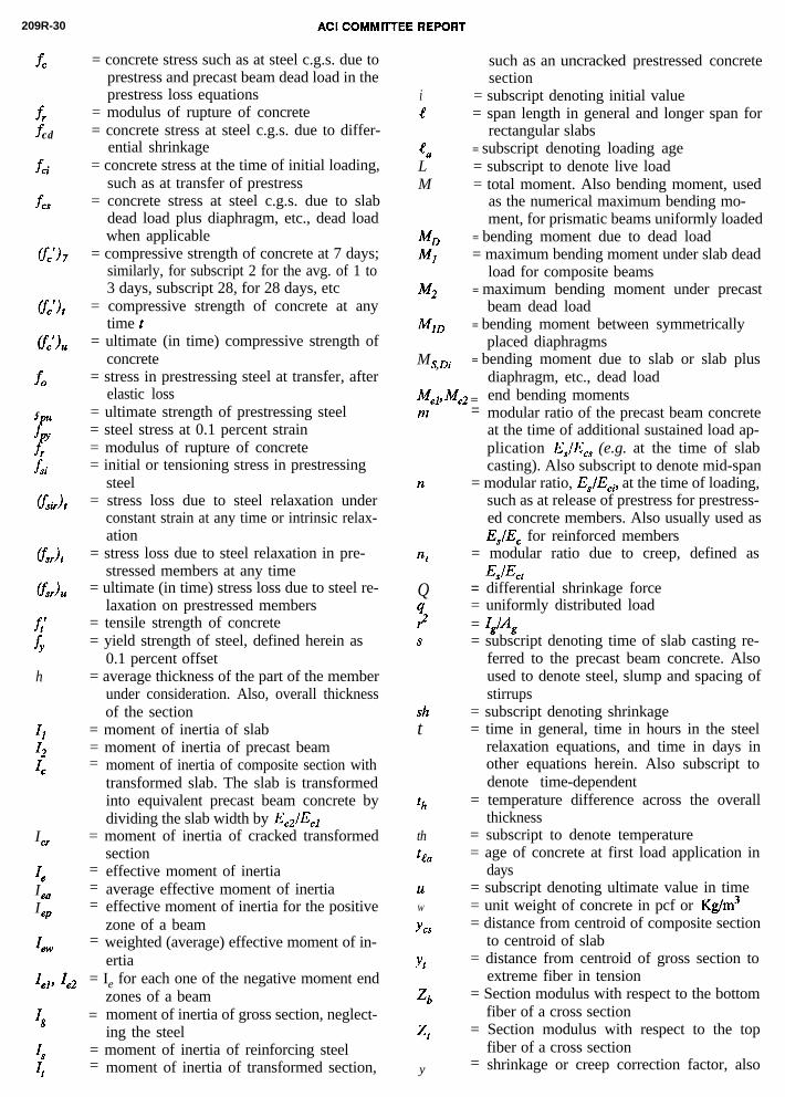
209R-30
fc
f,fcd
fci
fm
KY)7
fo
f
r
f
-6
Wt
6
fY
h
ICf
4
IeaI
eP
4w
= concrete stress such as at steel c.g.s. due toprestress and precast beam dead load in theprestress loss equations
= modulus of rupture of concrete= concrete stress at steel c.g.s. due to differ-
ential shrinkage= concrete stress at the time of initial loading,
such as at transfer of prestress= concrete stress at steel c.g.s. due to slab
dead load plus diaphragm, etc., dead loadwhen applicable
= compressive strength of concrete at 7 days;similarly, for subscript 2 for the avg. of 1 to3 days, subscript 28, for 28 days, etc
= compressive strength of concrete at anytime t
= ultimate (in time) compressive strength ofconcrete
= stress in prestressing steel at transfer, afterelastic loss
= ultimate strength of prestressing steel= steel stress at 0.1 percent strain= modulus of rupture of concrete= initial or tensioning stress in prestressing
steel= stress loss due to steel relaxation under
constant strain at any time or intrinsic relax-ation
= stress loss due to steel relaxation in pre-stressed members at any time
= ultimate (in time) stress loss due to steel re-laxation on prestressed members
= tensile strength of concrete= yield strength of steel, defined herein as
0.1 percent offset= average thickness of the part of the member
under consideration. Also, overall thicknessof the section
= moment of inertia of slab= moment of inertia of precast beam= moment of inertia of composite section with
transformed slab. The slab is transformedinto equivalent precast beam concrete bydividing the slab width by EC2/ECl
= moment of inertia of cracked transformedsection
= effective moment of inertia= average effective moment of inertia= effective moment of inertia for the positive
zone of a beam= weighted (average) effective moment of in-
ertia
Ielj Ie2 = Ie for each one of the negative moment endzones of a beam
Ig = moment of inertia of gross section, neglect-ing the steel
4 = moment of inertia of reinforcing steel
It = moment of inertia of transformed section,
such as an uncracked prestressed concretesection
i = subscript denoting initial valuee = span length in general and longer span for
rectangular slabs‘a = subscript denoting loading ageL = subscript to denote live loadM = total moment. Also bending moment, used
as the numerical maximum bending mo-ment, for prismatic beams uniformly loaded
MD = bending moment due to dead load4 = maximum bending moment under slab dead
load for composite beamsM2 = maximum bending moment under precast
beam dead loadMID = bending moment between symmetrically
placed diaphragmsMS,Di = bending moment due to slab or slab plus
diaphragm, etc., dead loadMe], Me2 = end bending momentsm
II
4
Q
::S
_-= modular ratio of the precast beam concrete
at the time of additional sustained load ap-plication Es/E,, (e.g. at the time of slabcasting). Also subscript to denote mid-span
= modular ratio, Es/E~i, at the time of loading,such as at release of prestress for prestress-ed concrete members. Also usually used asEs/EC for reinforced members
= modular ratio due to creep, defined asJv4t
= differential shrinkage force= uniformly distributed load= IslAg= subscript denoting time of slab casting re-
ferred to the precast beam concrete. Alsoused to denote steel, slump and spacing ofstirrups
sht
th
thtta
= subscript denoting shrinkage= time in general, time in hours in the steel
relaxation equations, and time in days inother equations herein. Also subscript todenote time-dependent
= temperature difference across the overallthickness
= subscript to denote temperature= age of concrete at first load application in
daysuW
YCS
Yt
= subscript denoting ultimate value in time= unit weight of concrete in pcf or Kg/m3= distance from centroid of composite section
to centroid of slab
‘b
4
= distance from centroid of gross section toextreme fiber in tension
= Section modulus with respect to the bottomfiber of a cross section
= Section modulus with respect to the topfiber of a cross section
y = shrinkage or creep correction factor, also

PREDICTION OF CREEP 209R-31
RRel
4
44Vs
YtYtl
yt2
used as the product of all applicable correc-tion factorsdifferential shrinkage strain, also subscriptdenoting differential strain or differentialstressshrinkage strain in in./in. or mm/mm at anytimeultimate (in time) shrinkage strain in inc./in.or mm/mmrelative humidity in percentprestress loss due to elastic shortening inpercent of initial tensioning stress or forceprestress loss due to steel relaxation in per-centtotal prestress loss in percent at any timeultimate (in time) prestress loss in percentcreep coefficient of precast beam concreteat time of slab castingcreep coefficient at any timecreep coefficient of the composite beamunder slab dead load, also creep coefficientat time fIcreep coefficient due to precast beam deadload
ultimate (in time) creep coefficientultimate (in time) creep coefficientus of the precast beam concrete correspond-ing to the age when the slab is cast for com-posite beamsdeflection coefficientdeflection coefficient for flat platesreduction factor to take into account theeffect of compression steel, movement ofneutral axis, and progressive cracking inreinforced flexural memberscross section shape coefficientdeflection coefficient for two-way slabsdeflection coefficient for warping w due toshrinkage or temperature changereinforcement ratio, A,/bd for crackedmembers, and AJAg for uncracked mem-bers. Used in percent in shrinkage warpingequationsmultiplier for additional long time deflec-tions due to creep and shrinkagecurvatureaging coefficient

Table 2.2.1 Values of the Constants a, B and a/B and the Time RatioFrom Eqs. (2-l) and (2-2).
Concrete AgeType Cement Constants Days Years
Time Ratio of a,6 and UltimateCuring Type a/B 3 7 14 21 28 56 91 1 10 (in time)
1I a= 4.0
Moist 6 = . .46 .70 .88 .96 1.0 1.08 1.12 1.16 1.17 1.18Cured III a = 2.3
P = .92 .59 .80 .92 .97 1.0 1.04 1.06 1.08 1.09 1.09(f’c)t/(f’c) 28 ’
I a = 1.0Eq. (2-l) Steam B = .95 .78 .91 .98 1.0 1.0 1.03 1.04 1.05 1.05 1.05
Cured III a= .70P = .98 .82 .93l .97 .99 1.0 1.0 1.01 1.01 1.02 1.02
Moist Ia/ B = 4.71 .39 .60 .75 .82(f’c),/(f’c),, .86 .92 .95 .99 1.0 1.0Cured III a/B = 2.5 .54 .74 .85 .89 .92 .96 .97 .99 1.0 1.0
Eq. (2-2)Steam I a& = 1.05 .74 .87 .93 .95 .96 .98 .99 1.0 1.0 1.0Cured III a/B = 0.71 .81 .91 .95 .97 .97 .99 .99 1.0 1.0 1.0

Table 2.2.2 Factors Affecting Concrete Creep and Shrinkage andVariables Considered in the Recommended Prediction Method.
Factors Variables Considered Standard Conditions
Concrete(Creep &Shrinkage)
MemberGeometry &Environment(Creep &Shrinkage)
Loading(Only Creep)
ConcreteComposition
InitialCuring
Environment
Geometry
LoadingHistory
StressConditions
Cement Paste Content Type of cement Type I and IIIWater-Cement Ratio Sl p 2 / in, (70 mm)Mix Proportions AiyContent 2.6 percentAggregate Characteristics Fine Aggregate Percentage 50 percentDegree of Compaction Cement Content 470 to 752 lb/cu3yd
(279 to 446 kg/m )
Length of Initial Curing Moist Cured 7 daysSteam Cured l-3 days
Curing Temperature Moist CuredSteam Cured
733;z;'F (2322°C)0
, (LlOOOC)Curing Humidity Relative Humidity 295 percent__-Concrete TemperatureConcrete Water Content
Concrete Temperature 73.4+4"F, (2322°C) -Ambient Relative Humidity 40%
Size and ShapeVolume-Surface Ratio, (v/s)
orMinimum Thickness
Concrete Age at Load Moist Cured 7 daysApplication Steam Cured l-3 daysDuration of Loading Period Sustained Load Sustained LoadDuration of Unloadins PeriodNumber of Load Cycles - -I I I
Type of Stress andDistribution Across theSection
Compressive Stress Axial Compression
Stress/Strength Ratio 1 Stress/Strength Ratio I LO.50 I

209R-34
AC
I CO
2F-
YSW
l c
0L l r
5%P
LDS
QJ
aE.C
ncl
2E;:
&d
d
d
2=f
zd
d
d
..
.E
-Elz
MM
ITT
EE
RE
PO
RT
-NdIti
E-
0tzrb
e
aj-
ii?=
:mc:S
-

PREDICTION OF CREEP 209R-35
Table 2.5.3 Shrinkage Correction Factorsfor Initial Moist Curing
I Moist curing duration,days
1 1.23 1.17 1.0
14 0.9328 0.86
I 90 0.75
Shrinkage Ycp
Table 2.5.4 Correction Factors forRelative Humidity, fromEqs. (2-14), (2-15), and(2-16).
RelativeHumidity,percent
Creep Shrinkage
yx yx
< 40 '1.00 >l.OO40 1.00 1.0050 0.94 0.9060 0.87 0.8070 0.80 0.7080 0.73 0.6090 0.67 0.30
100 0.60 0.00
Table 2.5.5.1 Correction Factors for AverageThickness of Members, fromEqs. (2-17) to (2-20)
Average Creep ShrinkageThicknessof Member* 'h 'h
ult. ult.in. mm Fl yr. value 51 yr. value2 51 1.30 1.30 1.35 1.353 76 1.17 1.17 1.25 1.254 104 1.11 1.11 1.17 1.175 127 1.04 1.04 1.08 1.08
Eqs. (2-17) (2-18) (2-19) (2-20)6 152 1.00 1.00 1.00 1.008 203 0.96 0.96 0.93 0.94
10 254 0.91 0.93 0.85 0.8812 305 0.86 0.90 0.77 0.8215 381 0.80 0.85 0.66 0.74
I*This method is recommended for averagethicknesses (part being considered) up toabout 12" to 15", (305 to 38 mm).

209R-36 ACI COMMITTEE REPORT
Table 2.5.5.2 Correction Factorsfor Volume-SurfaceRatios, from Eqs.(2-21) and (2-22)
Volume- Creep ShrinkageSurfaceRatio Qs Yv/s
in. mm (2-21) (2-22)
1.0 25 1.09 1.061.5 38 1.00 1.002 51 0.92 0.943 76 0.81 0.844 102 0.75 0.745 127 0.72 0.666 152 0.70 0.588 203 0.68 0.46
10 254 0.67 0.36
Examples:
For a rectangular section6"x 12" (150 x 35Omm), v/s =2.0" (51 mm). For theStandard ASSHTO I-Beams,v/s varies from 3.0" to 4.7",(76 to 12Omm).
Table 2.7.1 Correction Factors Used in Example 2.7
Conditions
tga = 28 daysA = 70%h = 8 in (200 mm)
= 2.5 in (63 mm)$ = 60%C = 752 lbs/cu yd
(446kg/&a = 7%
Factors' product
Creep
Eq.
(2-11) 0.84(2-14) 0.80(2-17) 0.96(2-23) 0.99(2-25) 1.02
(2129) 1.09
Factor
Q= 0.71 Y sh = 0.68
Shrinkage
Eq.
(2-15)(2-19)(2-24)(2-27)
(2-28)(2-30)
Factor
o.;o0.930.991.02
1.021.01

PREDICTION OF CREEP 209R-37
Table 2.7.2 Creep Factors and Shrinkage Strains inExample 2.7
I
Concrete daysage, 56 118 208 393
Time after initialcuring, days 49 111 201 386
1
Time after loadapplication, days 28 90 180 365
%, Eq. (2-8) 0.72 1.02 1.18 1.32
( ‘sh)t x lo+ Eq. (2.9) 309 403 451 486
( 'sh)6 x 10%for tga = 56 days 0 93 142 1768 4
Table 2.9.1 Suggested Values for the Degree of Saturation
Concrete Member EnvironmentalConditions
Degree ofSaturation
Immersed structures, high humidityconditions. I Saturated I I--0 0
Mass concrete pours, thick walls,beams, columns and slabs,
Between partiallysaturated and
particularly where surface is sealed. saturated0.72-1
1.3
External slabs, walls, beams,columns, and roofs allowed todry out or internal walls, columnsslabs, not sealed (e.g. by mosaic ortiling) and where underfloor heatingor central heating exists.
Partially saturateddecreasing withtime to the dryerconditions
0.83
to
1.11
1.5
to
2.0

209R-38 ACI COMMITTEE REPORT
Table 2.9.2 Average ThermalCoefficient ofExpansion of Aggregate
rRock Group
ChertQuartziteQuartzSandstoneMarbleSiliceous
limestoneGraniteDoleriteBasaltLimestone
c
lo-6/oF
6.6 11.85.7 10.36.2 11.15.2 9.34.6 8.3
4.6 8.33.8 6.83.8 6.83.6 6.43.1 5.5
,
Table 2.9.3 Range of the Concrete Thermal Coefficientof Expansion
Aggregate, ea Concrete, eth
Rock Group lo-6/oF lo-6/oc lo-6/oF lo-6/oc
Chert 4.1-7.2 7.4-13.0 6.3-6.8 11.4-12.2Quartzite 3.9-7.3 7.0-13.2 6.5-8.1 11.7-14.6Quartz 5.0-7.3 9.0-13.2Sandstone 2.4-6.7 4.3-12.1 5.1-7.4 9.2-13.3Marble 1.20-8.9 2.2-16.0 2.4-4.1 4.4-7.4Siliceous
1 imestone 2.0-5.4 3.6-9.7 4.5-6.1 8.1-11.0Granite 1.0-6.6 1.8-11.9 4.5-5.7 8.1-10.3Dolerite 2.5-4.7 4.5-8.5 - - - -Basalt 2.2-5.4 4.0-9.7 4.4-5.8 7.9-10.4Limestone 1.0-6.5 1.8-11.7 2.0-5.7 4.3-10.3
*Test data for the concrete does not necessarilycorrespond to test data for the aggregate in Table2.9.2. These ranges are limited to the research workcompiled in Reference 76.

Table 3.5.1 Reduction Factors <r, Srvu and Sr mu from Eqs. (3-7),(3-8), and (3-9).
Eq.(3-7) ‘;o;u Eq.(3-8) s;o;u Eq.(3-9)5 T
AilAs For'cr Vu=2.o sr Tu=2.0 5r Tu=2.0
0 0.85 1.7 1.0 2.0 1.0 2.0I
0.5 0.625 1.25 0.70 1.4 0.667 1.3
1.0 1 0.40 1 0.8 1 0.40 I 0.8 I 0.5 I 1.0 I
c
Table 3.7.1 Intrinsic Relaxation Stress Loss (Steel Relaxation Under Constant Strain).
Wire or Strand (fsir)t for fsi/fpY 0.60(fsir)u/fsi
at t=105 hours fPYand tl = 1 hour at 0.1% strain
[f l
Stress 0.1 fsi s'
relieved fPY-0.55 loglO(t/tl)
I (0.025 to 0.175) fpy = 0.85 fpu
SteelStabilized
re Gation)'Lp-0.55 1 log10(t/t1) (0.0055 to 0.39) fPY = 0.90 f pu

Table 4.2.1 Values of M, 5 and SW for Beams of Uniform Sectionand Uniform Load
Boundary Conditions M 5 5WI
Cantilever beam -q R2/2 l/4 l/2, 1
Simple beam +q t2/8 5/48 l/81
Hinged-fixed beam (one end continuous) -q a2/8 8/185 11/128
1 Fixed-fixed beam (both ends continuous) 1 -q g2/12 1 l/32 1 l/16 I
Table 3.7.2 Relaxation Reduction Factor
fsi/fpy
0.000.050.10
w 0.150.200.300.400.50
0.50 ~ 0.55 0.60 0.65 0.70 0.75 0.80
0.0000.0000.0000.0000.0000.0000.000
1.000 1.000 1.000 1.000 1.000 1.000/ 0.547 0.729 0.798' 0.835 0.857 0.8720.289 0.516 0.627 0.689 0.729 0.7560.172 0.361 0.486 0.564 0.615 0.6520.099 0.262 0.375 0.458 0.516 0.5580.013 0.150 0.238 0.305 0.361 0.4060.000 0.077 0.159 0.216 0.262 0.3000.000 0.029 0.102 0.157 0.197 0.230
Table 3.7.3 Minimum Time Intervalsto Compute Steel Relaxation
Step BeginningTime, t1 End time, t
Pretensioned:anchorage ofprestressing Age at pre-
1 steel. stressing ofPost-tensioned: concreteend of curingof concrete.
Age = 30 days,or time when a
2 End of Step 1 member is sub-jected to loadin addition toits own weight
3 End of Step 2 Age = 1 year
4 End of Step 3 End of servicelife

PREDICTION OF CREEP 209R-41
Table 4.4.1.1 Suggested Modular Ratios for Prestressed Beams
Sand-Modular Type of Concrete Normal light All-lightRatio Weight Weight Weight
w in pcf, (kg/m3)145 120 100
(2323) (1922) (1602)
Curing M.C. S.C. M.C. S.C. M.C. S.C.
n At release of prestress 7.3 7.3 9.8 9.8 12.9 12.9
For the time between pre-stressing and slab casting
m = 3 weeks, 6.1 6.2 8.1 8.3 10.7 10.91 month, 6.0 6.2 8.0 8.2 10.5 10.72 months, 5.9 7.9 8.2 8.2 10.3 10.63 months, 5.8 6.0 7.7 8.0 10.2 10.5
The above average modular ratios are based on fci = 4000 to 4500 psi (27.6
to 31.0 MPa) for both moist cured and steam cured concrete and type I
cement; up to 3-mths fc = 6360 to 7150 psi (43.9 to 49.3 MPa), using Eq.
(2-l) for moist cured, and 3-mths fi = 6050 to 6800 psi (41.7 to 46.9 MPA),
using Eq. (2-l) for steam cured concrete. Es = 27 x 106 psi (18.62X10⁴ MPa)
for ASTM A-416 Grade 250 (1725 Mpa) strands and Es = 28 x 106 psi (19.3 x
10 4 MPa)) for Grade 270 (1860 MPa) prestressing strands.
M.C. = Moist Cured, S.C. = Steam Cured

AC
I CO
MM
ITT
EE
RE
PO
RT
-8
ZF
4rDt-l-
col-l
d
0!A\
sL

PREDICTION OF CREEP 209R-43
Table 4.4.2.1 Common Cases of Prestress MomentDiagrams and Equations forComputing Camber
Prestress Beam

209R-44 ACI COMMITTEE REPORT
Table 4.6.1 Material and Section Properties, Parameters andConditions for Example 4.6, (U.S. Customery Units)
UNSHORED COMPOSITE GIRDER Material Properties:
4 9 2 "V
Steam Cured Normal Weight Concrete
Afpu
= 270 ksi=b
f'. = 4000 psi, fc = 5000 psi
D::k f; = 4000 psi
EGirder/ESlab = E2/El = 3.89/3.64 = 1.07E . = 3.64 x 10⁶psi, Ec = 3.89 x 10 psi
Section Properties and Loading from. . . . . . . . . . . PCI Handbook
Girder:A A S H T O I V
S I M P L E S P A N
Calculated Section Properties and Loading -- Composite Section:
Modif ied Slab Area = 7 x 92/1.07 = 602 in2, yb = (789 x 24.73 + 602 x
57.50)/(789 + 602) = 38.91", Ig = 260,740 + 789(38.91 - 24.73)2 + 92 x 73
/(l2 x 1.07) + 602(57.50 - 38.91)2 = 629,890 in4
Zt= 629,890/(61.00 - 38.91) = 28,510 in3, zb = 629,890/38.91 = 16,190 in3
Including l/2" w.s., Slab D.L. = ws = (7.5 x 92)(150/144) = 719 lb/ftHS 20-44 AASHTO Loading, Impact = 50/(80 + 125) = 0.25
Assume Deck Slab Cast 2 Months After Prestressing
Area of One l/2" Strand = 0.153 in2 (Fig. 11.3.3, PCI Handbook)
Aps = (32) (0.153) = 4.90 in2, fsi = (0.70)(270) = 189 ksi
ID = wDL2/8 = (822)(80)2/8 = 657,600 ft-lb, MS,Di = (719)(80)2/8 + 50,000
q =625,200 ft-lb, MD+MS, Di= 1,282,800 ft-lb, Interior Girder ML + I = (1165 --
AASHTO Table) (l/2 -- Single Wheels)(l.25 -- L + 1)(7.67/5.5 -- AASHTO, S/5.5)
= 1,015,400 ft-lb
Assume 60% Ambient Humidity
Other Parameters: n = 7.3, m = 6.1 (Table 4.4.1.1), vu = 1.64, vs = vt,
yRa = (0.54) (1.64) (0.78) = 0.69, where vt/ vu = 0.54 (Eq. 2-8)
and creepy,= 0.78 (Eq. 2-12), ( Esh)u = 487 x loo6 in/in,(m/m)
-s/Fo = 0.14, F,/F, = 0.18 (Table 4.4.1.2),
and (1 + n PC& = 1.25 (Design simplification)

PREDICTION OF CREEP 209R-45
Table 4.6.2 Material and Section Properties, Parameters andConditions for Example 4.6 (SI Units)
UNSHORED COMPOSITE GIRDER Material Properties:4
2.34mH Steam Cured Normal Weight Concrete
178mm L fPu
= 1862 MPa
= 27.6 MPa, fk = 34.5 MPa
= 27.6 MPa
EGirder/ESlab = E2/El = 2.68/2.51 = 1.070 E ci = 2.51x10⁴MPa, Ec = 2.68x10⁴MPa
Section Properties and Loading from. . . . . . . . . . . PCI Handbook
Girder:A A S H T O IV
S I M P L E S P A N
Calculated Section Properties and Loading -- Composite Section:
Modified Slab Area = 0.178x2.34/107 = 0.389m2, yb=(0.509x0.628+0.389x
1.46)/(0.509+0.389)=988m, I =O.1O85+O.5O9(O.988-O.623)2+2.34xO.1783
/(12x1.07)+0.389(1.46-0.988) =0.2622m492
Zt=0.2622/(1.549-0.988)=0.4674m3, Zb=0.2622/.988=0.2653m3
Including 12.7mm w.s., Slab D.L.=wS=(0.191x2.34)x2.4x9.807=10.5KN/m
HS20-44 AASHTO Loading, Impact=50/(80+125)=0.25
Assume Deck Slab Cast 2 Months After Prestressing
Area of One 12.7mm Strand=9.87x10⁵m2 (Fig. 11.3.3, PCI Handbook)
Aps=(32)(9.87x10~5)=3.16x10~3m2, fsi=(0.70)1862-1303MPa
MD=wdL2/8=12(24.38)2/8=891.6KNm, f,i=(0.70)1862-1303MPa
=847.9KNm, MD+MS Di =1739.5KNm, Interior Girder ML+I=(1579.5--
AASHTO Table) (1/2--Single Wheels)(l.25--L+I)(2.34x3.28/5.5--AASHTO, S/5.5)
=13.76.7KNm
Assume 60% Ambient Relative Humidity
Other Parameters: n=7.3,m=6.1 (Table 4.4.1.1), vu=1.64,vs =vt,
yRa =(0.54)(1.64)(0.78)=0.69, where vt/vu=0.54 (Eq. 2-8)
and creepYka =0.78 (Eq. 2-12), ( ~sh)u=487x10~6in/in, (m/m)
F,/F,=O.14, F,/F, = 0.18 (Table 4.4.1.2),
and (l+n@S s) = 1.25 (Design simplification)

Table 4.6.3 Term by Term Loss of Prestress and Ultimate (in time) MidspanLoss for Example in 4.6, Composite AASHTO Type IV Girder,Normal Weight Concrete
Losses Gains
Creep Creep Elas- Diff.Before After tic, Creep, Shrink-
Elas- Slab Slab Shrink- Relax- Due to Due to age and TotalUnits tic Cast Cast age ation Slab Slab Creep Loss
I
ksi 14.10 11.61 3.93 10.91 14.18 -3.73 -1.58 -3.44 45.98
MPa 97.22 80.05 27.10 75.22 97.77 -25.72 -10.89 -23.72 317.02
% 7.46 6.14 2.08 5.77 7.50 -I.97 -0.84 -1.82 24.3
Table 4.6.4 Term by Term Camber, Deflection and Ultimate Midspan Valuesfor Example in Composite AASHTO Type IV Girder, NormalWeight Concrete
Defl.Initial Creep Creep Creep Creep Elastic Creep Due To
Initial Defl. Camber Camber Defl. Defl. Defl. Defl. Diff.Camber Due To Up To After Up To After Due To Due To Shrink-Due To Beam Slab Slab Slab Slab Slab Slab age and
Units Prestr. D.L. Cast Cast Cast Cast Cast D.L. Creep Total
Inch 1.93 -0.80 1.22 0.50 -0.71 -0.25 -0.74 -0.39 -0.63 0.13
(mm) 49.0 -20.3 31.0 12.7 -18.0 -6.3 -18.8 -0.9 -16.0 3.3
Live Load Plus Impact Deflection = -0.50", (-12.7mm)

PREDICTION OF CREEP 209R-47
Table 4.7.1 Elastic Deflection Coefficients cfp and $_ws (1x10 -5 ) forInterior Panel
Type Interior Panel Support R/S
1.0 1.1 1.7 1.3 1.4 1.5
Cf(Flat Blates)
Zero beamedge 0.0c/R 0.1*
581 487 428 387 358 337stiffness 441 372 320 283 260 243
Elastically support- Relativelyed edges. The appro- flexible 380 330 290 260 240 230priate coefficient is edge beams to to to to to toin between the case (total depth 250 230 210 190 170 160
5of zero edge beams about 2t)*
tws stiffness (flate plate) Relatively(Two-way slabs) and infinitely stiff stiff edge 290 260 230 210 190 180
edge beams (rigid sup- beams (total to to to to to toports). depth 170 140 120 105 90 80
about 3t)*Rigids supports. Built-in edges oninfinitely stiff edge beams 126 102 83 67 54 43
*approximate values c/R = column/span ratioR/S = longer span/shorter span ratio
Table 5.1.1 Aging Coefficient
'%a vutll in days
4
dayslo1 lo2 lo3 I 104
0.5 .525 .804 .811 .8091.5 .728 .826 .825 .820
lo1 2.5 .774 .842 .837 .8303.5 .806 .856 .848 .839
1 I 1 1 Im I 1 1
0.5 .505 .888 .916 .915,
10' 2.5 .8041.5 .739 .919 .932 .928
.935 .943 .9383.5 .839 .946 .951 .946
0.5 .511 .912 .973 .981
2.5 .7951.5 .732 .943 .981 .985
lo3 .956 .985 .9883.5 .830 .964 .987 .990
0.5 .501 .899 .976 .994
2.5 .7811.5 .717 .934 .983 .995
lo4 .949 .986 .9963.5 .818 .958 .989 .997