2080-WD010B-EN-P Micro800 Digital Relay Output Plug...
12
Wiring Diagrams Micro800 Digital Relay Output Plug-in Module Catalog Number 2080-OW4I http://www.rockwellautomation.com/literature/ FR Cette publication est disponible en français sous forme électronique (fichier PDF). Pour la télécharger, rendez-vous sur la page Internet indiquée ci-dessus. IT Questa pubblicazione è disponibile in Italiano in formato PDF. Per scaricarla collegarsi al sito Web indicato sopra. DE Diese Publikation ist als PDF auf Deutsch verfügbar. Gehen Sie auf die oben genannte Web-Adresse, um nach der Publikation zu suchen und sie herunterzuladen. ES Esta publicación está disponible en español como PDF. Diríjase a la dirección web indicada arriba para buscar y descarga esta publicación. PT Esta publicação está disponível em portugués como PDF. Vá ao endereço web que aparece acima para encontrar e fazer download da publicação. ZH ZC KO
Transcript of 2080-WD010B-EN-P Micro800 Digital Relay Output Plug...
Wiring Diagrams
Micro800 Digital Relay Output Plug-in Module
Catalog Number 2080-OW4I
http://www.rockwellautomation.com/literature/
FR Cette publication est disponible en français sous forme électronique (fichier PDF). Pour la télécharger, rendez-vous sur la page Internet indiquée ci-dessus.
IT Questa pubblicazione è disponibile in Italiano in formato PDF. Per scaricarla collegarsi al sito Web indicato sopra.
DEDiese Publikation ist als PDF auf Deutsch verfügbar. Gehen Sie auf die oben genannte Web-Adresse, um nach der Publikation zu suchen und sie herunterzuladen.
ES Esta publicación está disponible en español como PDF. Diríjase a la dirección web indicada arriba para buscar y descarga esta publicación.
PT Esta publicação está disponível em portugués como PDF. Vá ao endereço web que aparece acima para encontrar e fazer download da publicação.
ZH
ZC
KO
2 Micro800 Digital Relay Output Plug-in Module
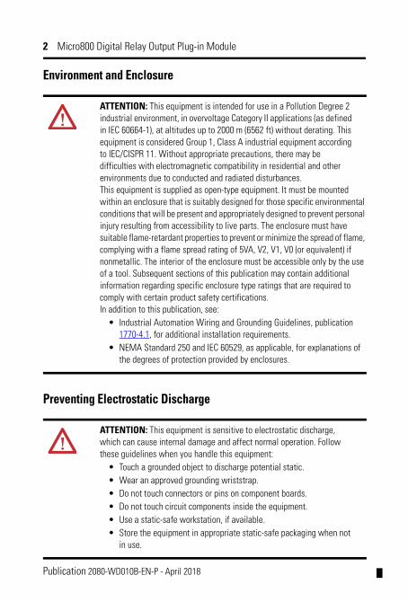
Environment and Enclosure
Preventing Electrostatic Discharge
ATTENTION: This equipment is intended for use in a Pollution Degree 2 industrial environment, in overvoltage Category II applications (as defined in IEC 60664-1), at altitudes up to 2000 m (6562 ft) without derating. This equipment is considered Group 1, Class A industrial equipment according to IEC/CISPR 11. Without appropriate precautions, there may be difficulties with electromagnetic compatibility in residential and other environments due to conducted and radiated disturbances.This equipment is supplied as open-type equipment. It must be mounted within an enclosure that is suitably designed for those specific environmental conditions that will be present and appropriately designed to prevent personal injury resulting from accessibility to live parts. The enclosure must have suitable flame-retardant properties to prevent or minimize the spread of flame, complying with a flame spread rating of 5VA, V2, V1, V0 (or equivalent) if nonmetallic. The interior of the enclosure must be accessible only by the use of a tool. Subsequent sections of this publication may contain additional information regarding specific enclosure type ratings that are required to comply with certain product safety certifications.In addition to this publication, see:
• Industrial Automation Wiring and Grounding Guidelines, publication 1770-4.1, for additional installation requirements.
• NEMA Standard 250 and IEC 60529, as applicable, for explanations of the degrees of protection provided by enclosures.
ATTENTION: This equipment is sensitive to electrostatic discharge, which can cause internal damage and affect normal operation. Follow these guidelines when you handle this equipment:
• Touch a grounded object to discharge potential static.• Wear an approved grounding wriststrap.• Do not touch connectors or pins on component boards.• Do not touch circuit components inside the equipment.• Use a static-safe workstation, if available.• Store the equipment in appropriate static-safe packaging when not
in use.
Publication 2080-WD010B-EN-P - April 2018
Micro800 Digital Relay Output Plug-in Module 3
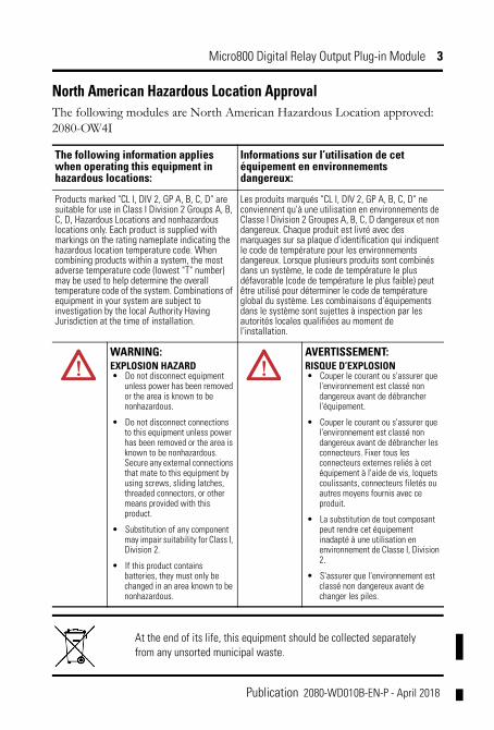
North American Hazardous Location ApprovalThe following modules are North American Hazardous Location approved: 2080-OW4I
The following information applies when operating this equipment in hazardous locations:
Informations sur l’utilisation de cet équipement en environnements dangereux:
Products marked "CL I, DIV 2, GP A, B, C, D" are suitable for use in Class I Division 2 Groups A, B, C, D, Hazardous Locations and nonhazardous locations only. Each product is supplied with markings on the rating nameplate indicating the hazardous location temperature code. When combining products within a system, the most adverse temperature code (lowest "T" number) may be used to help determine the overall temperature code of the system. Combinations of equipment in your system are subject to investigation by the local Authority Having Jurisdiction at the time of installation.
Les produits marqués "CL I, DIV 2, GP A, B, C, D" ne conviennent qu'à une utilisation en environnements de Classe I Division 2 Groupes A, B, C, D dangereux et non dangereux. Chaque produit est livré avec des marquages sur sa plaque d'identification qui indiquent le code de température pour les environnements dangereux. Lorsque plusieurs produits sont combinés dans un système, le code de température le plus défavorable (code de température le plus faible) peut être utilisé pour déterminer le code de température global du système. Les combinaisons d'équipements dans le système sont sujettes à inspection par les autorités locales qualifiées au moment de l'installation.
WARNING: EXPLOSION HAZARD• Do not disconnect equipment
unless power has been removed or the area is known to be nonhazardous.
• Do not disconnect connections to this equipment unless power has been removed or the area is known to be nonhazardous. Secure any external connections that mate to this equipment by using screws, sliding latches, threaded connectors, or other means provided with this product.
• Substitution of any component may impair suitability for Class I, Division 2.
• If this product contains batteries, they must only be changed in an area known to be nonhazardous.
AVERTISSEMENT: RISQUE D’EXPLOSION• Couper le courant ou s'assurer que
l'environnement est classé non dangereux avant de débrancher l'équipement.
• Couper le courant ou s'assurer que l'environnement est classé non dangereux avant de débrancher les connecteurs. Fixer tous les connecteurs externes reliés à cet équipement à l'aide de vis, loquets coulissants, connecteurs filetés ou autres moyens fournis avec ce produit.
• La substitution de tout composant peut rendre cet équipement inadapté à une utilisation en environnement de Classe I, Division 2.
• S'assurer que l'environnement est classé non dangereux avant de changer les piles.
At the end of its life, this equipment should be collected separately from any unsorted municipal waste.
Publication 2080-WD010B-EN-P - April 2018
4 Micro800 Digital Relay Output Plug-in Module
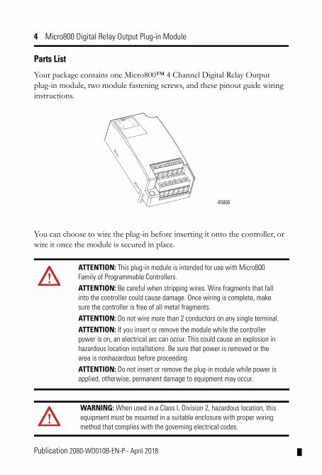
Parts List
Your package contains one Micro800™ 4 Channel Digital Relay Output plug-in module, two module fastening screws, and these pinout guide wiring instructions.
You can choose to wire the plug-in before inserting it onto the controller, or wire it once the module is secured in place.
ATTENTION: This plug-in module is intended for use with Micro800 Family of Programmable Controllers.
ATTENTION: Be careful when stripping wires. Wire fragments that fall into the controller could cause damage. Once wiring is complete, make sure the controller is free of all metal fragments.
ATTENTION: Do not wire more than 2 conductors on any single terminal.
ATTENTION: If you insert or remove the module while the controller power is on, an electrical arc can occur. This could cause an explosion in hazardous location installations. Be sure that power is removed or the area is nonhazardous before proceeding.
ATTENTION: Do not insert or remove the plug-in module while power is applied, otherwise, permanent damage to equipment may occur.
WARNING: When used in a Class I, Division 2, hazardous location, this equipment must be mounted in a suitable enclosure with proper wiring method that complies with the governing electrical codes.
45866
Publication 2080-WD010B-EN-P - April 2018
Micro800 Digital Relay Output Plug-in Module 5
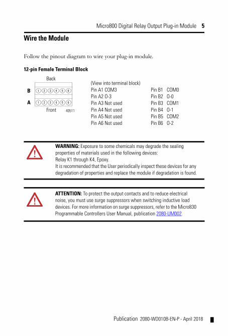
Wire the Module
Follow the pinout diagram to wire your plug-in module.
12-pin Female Terminal Block
WARNING: Exposure to some chemicals may degrade the sealing properties of materials used in the following devices:Relay K1 through K4, Epoxy.It is recommended that the User periodically inspect these devices for any degradation of properties and replace the module if degradation is found.
ATTENTION: To protect the output contacts and to reduce electrical noise, you must use surge suppressors when switching inductive load devices. For more information on surge suppressors, refer to the Micro830 Programmable Controllers User Manual, publication 2080-UM002.
1 2 3 4
1 2 3 4
5 6
5 6
(View into terminal block)Pin A1 COM3 Pin B1 COM0Pin A2 O-3 Pin B2 O-0Pin A3 Not used Pin B3 COM1Pin A4 Not used Pin B4 O-1Pin A5 Not used Pin B5 COM2Pin A6 Not used Pin B6 O-2
Back
A40511
B
Front
Publication 2080-WD010B-EN-P - April 2018

6 Micro800 Digital Relay Output Plug-in Module
Insert Module into Controller Follow the instructions to insert and secure the plug-in module to the controller.
1. Position the plug-in module with the terminal block facing the front of the controller as shown.
2. Snap the module into the module bay.
3. Using a screwdriver, tighten the 10…12 mm (0.39…0.47 in.) M3 self tapping screw to torque specifications.
WARNING: If you connect or disconnect wiring while the field-side power is on, an electrical arc can occur. This could cause an explosion in hazardous location installations. Be sure that power is removed or the area is nonhazardous before proceeding.
WARNING: If you connect or disconnect wiring while the field-side power is on, an electrical arc can occur. This could cause an explosion in hazardous location installations. Be sure that power is removed or the area is nonhazardous before proceeding.
44012
Publication 2080-WD010B-EN-P - April 2018
Micro800 Digital Relay Output Plug-in Module 7
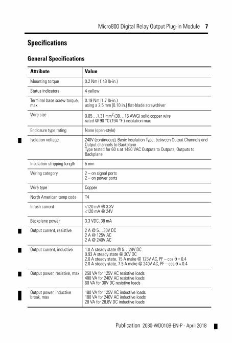
Specifications
General Specifications
Attribute Value
Mounting torque 0.2 Nm (1.48 lb-in.)
Status indicators 4 yellow
Terminal base screw torque,max
0.19 Nm (1.7 lb-in.)using a 2.5 mm [0.10 in.] flat-blade screwdriver
Wire size 0.05…1.31 mm2 (30…16 AWG) solid copper wirerated @ 90 °C (194 °F ) insulation max
Enclosure type rating None (open-style)
Isolation voltage 240V (continuous), Basic Insulation Type, between Output Channels and Output channels to BackplaneType tested for 60 s at 1480 VAC Outputs to Outputs, Outputs to Backplane
Insulation stripping length 5 mm
Wiring category 2 – on signal ports2 – on power ports
Wire type Copper
North American temp code T4
Inrush current <120 mA @ 3.3V<120 mA @ 24V
Backplane power 3.3 VDC, 38 mA
Output current, resistive 2 A @ 5…30V DC2 A @ 125V AC2 A @ 240V AC
Output current, inductive 1.0 A steady state @ 5…28V DC0.93 A steady state @ 30V DC2.0 A steady state, 15 A make @ 125V AC, PF – cos θ = 0.42.0 A steady state, 7.5 A make @ 240V AC, PF – cos θ = 0.4
Output power, resistive, max 250 VA for 125V AC resistive loads480 VA for 240V AC resistive loads60 VA for 30V DC resistive loads
Output power, inductive break, max
180 VA for 125V AC inductive loads180 VA for 240V AC inductive loads28 VA for 28.8V DC inductive loads
Publication 2080-WD010B-EN-P - April 2018
8 Micro800 Digital Relay Output Plug-in Module
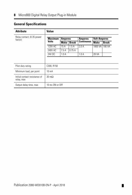
Relay contact, (0.35 power factor)
Pilot duty rating C300, R150
Minimum load, per point 10 mA
Initial contact resistance of relay, max
30 mΩ
Output delay time, max 10 ms ON or OFF
General Specifications
Attribute Value
Maximum Volts
Amperes Amperes Continuous
Volt-AmperesMake Break Make Break
120V AC 15 A 1.5 A 2.0 A 1800 VA 180 VA240V AC 7.5 A 0.75 A24V DC 1.0 A 1.0 A 28 VA
Publication 2080-WD010B-EN-P - April 2018
Micro800 Digital Relay Output Plug-in Module 9
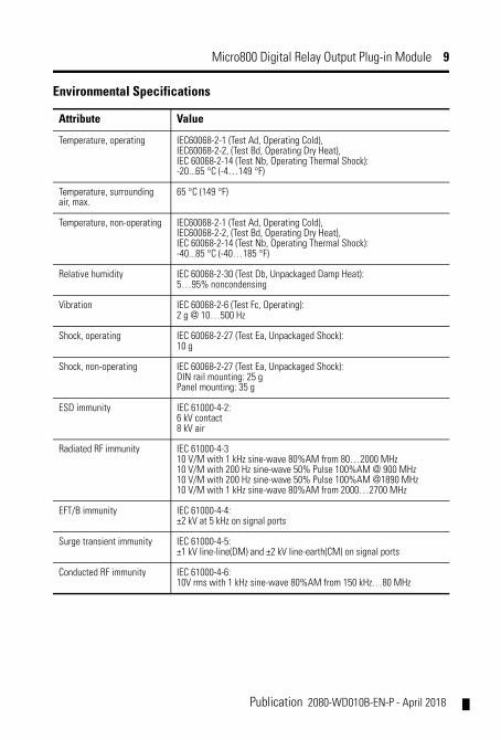
Environmental Specifications
Attribute Value
Temperature, operating IEC60068-2-1 (Test Ad, Operating Cold),IEC60068-2-2, (Test Bd, Operating Dry Heat),IEC 60068-2-14 (Test Nb, Operating Thermal Shock):-20...65 °C (-4…149 °F)
Temperature, surrounding air, max.
65 °C (149 °F)
Temperature, non-operating IEC60068-2-1 (Test Ad, Operating Cold),IEC60068-2-2, (Test Bd, Operating Dry Heat),IEC 60068-2-14 (Test Nb, Operating Thermal Shock):-40...85 °C (-40…185 °F)
Relative humidity IEC 60068-2-30 (Test Db, Unpackaged Damp Heat):5…95% noncondensing
Vibration IEC 60068-2-6 (Test Fc, Operating):2 g @ 10…500 Hz
Shock, operating IEC 60068-2-27 (Test Ea, Unpackaged Shock):10 g
Shock, non-operating IEC 60068-2-27 (Test Ea, Unpackaged Shock):DIN rail mounting: 25 gPanel mounting: 35 g
ESD immunity IEC 61000-4-2:6 kV contact8 kV air
Radiated RF immunity IEC 61000-4-310 V/M with 1 kHz sine-wave 80%AM from 80…2000 MHz10 V/M with 200 Hz sine-wave 50% Pulse 100%AM @ 900 MHz10 V/M with 200 Hz sine-wave 50% Pulse 100%AM @1890 MHz10 V/M with 1 kHz sine-wave 80%AM from 2000…2700 MHz
EFT/B immunity IEC 61000-4-4:±2 kV at 5 kHz on signal ports
Surge transient immunity IEC 61000-4-5:±1 kV line-line(DM) and ±2 kV line-earth(CM) on signal ports
Conducted RF immunity IEC 61000-4-6:10V rms with 1 kHz sine-wave 80%AM from 150 kHz…80 MHz
Publication 2080-WD010B-EN-P - April 2018
10 Micro800 Digital Relay Output Plug-in Module
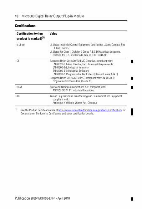
Certifications
Certification (when
product is marked)(1)Value
c-UL-us UL Listed Industrial Control Equipment, certified for US and Canada. See UL File E322657
UL Listed for Class I, Division 2 Group A,B,C,D Hazardous Locations, certified for U.S. and Canada. See UL File E334470.
CE European Union 2014/30/EU EMC Directive, compliant with:EN 61326-1; Meas./Control/Lab., Industrial RequirementsEN 61000-6-2; Industrial ImmunityEN 61000-6-4; Industrial EmissionsEN 61131-2; Programmable Controllers (Clause 8, Zone A & B)
European Union 2014/35/EU LVD, compliant with:EN 61131-2;Programmable Controllers (Clause 11)
RCM Australian Radiocommunications Act, compliant with:AS/NZS CISPR 11; Industrial Emissions
KC Korean Registration of Broadcasting and Communications Equipment, compliant with:Article 58-2 of Radio Waves Act, Clause 3
(1) See the Product Certification link at http://www.rockwellautomation.com/products/certification/ for Declaration of Conformity, Certificates, and other certification details.
Publication 2080-WD010B-EN-P - April 2018
Micro800 Digital Relay Output Plug-in Module 11
Notes:
Publication 2080-WD010B-EN-P - April 2018
Rockwell Automation SupportRockwell Automation provides technical information on the Web to assist you in using its products. At http://www.rockwellautomation.com/support/, you can find technical manuals, a knowledge base of FAQs, technical and application notes, sample code and links to software service packs, and a MySupport feature that you can customize to make the best use of these tools.
For an additional level of technical phone support for installation, configuration and troubleshooting, we offer TechConnect support programs. For more information, contact your local distributor or Rockwell Automation representative, or visit http://www.rockwellautomation.com/support/.
Installation AssistanceIf you experience a problem within the first 24 hours of installation, please review the information that's contained in this manual. You can also contact a special Customer Support number for initial help in getting your product up and running.
New Product Satisfaction ReturnRockwell Automation tests all of its products to ensure that they are fully operational when shipped from the manufacturing facility. However, if your product is not functioning and needs to be returned, follow these procedures.
Documentation FeedbackYour comments will help us serve your documentation needs better. If you have any suggestions on how to improve this document, complete this form, publication RA-DU002, available at http://www.rockwellautomation.com/literature/.
United States or Canada 1.440.646.3434
Outside United States or Canada
Use the Worldwide Locator at http://www.rockwellautomation.com/support/americas/phone_en.html, or contact your local Rockwell Automation representative.
United States Contact your distributor. You must provide a Customer Support case number (call the phone number above to obtain one) to your distributor to complete the return process.
Outside United States Please contact your local Rockwell Automation representative for the return procedure.
Publication 2080-WD010B-EN-P - April 2018 PN-487287
Allen-Bradley, Rockwell Automation, Micro800, and TechConnect are trademarks of Rockwell Automation, Inc.Trademarks not belonging to Rockwell Automation are property of their respective companies.
Rockwell Automation maintains current product environmental information on its website athttp://www.rockwellautomation.com/rockwellautomation/about-us/sustainability-ethics/product-environmental-compliance.page.
Supersedes Publication 2080-WD010A-EN-P - February 2012 Copyright © 2018 Rockwell Automation, Inc. All rights reserved. Printed in Singapore.