2080-QS003A-EN-E Micro800 Programmable …...Micro800 Programmable Controllers: Getting Started with...
62
Micro800 Programmable Controllers: Getting Started with PanelView Plus – Online Variable Browsing, Data Values Upload/Download, and Variable Import/Export Catalog Numbers Bulletin 2080-LC20, 2080-LC30, 2080-LC50 Quick Start
Transcript of 2080-QS003A-EN-E Micro800 Programmable …...Micro800 Programmable Controllers: Getting Started with...

Micro800 Programmable Controllers: Getting Started with PanelView Plus– Online Variable Browsing, Data Values Upload/Download, and Variable Import/ExportCatalog Numbers Bulletin 2080-LC20, 2080-LC30, 2080-LC50
Quick Start

Important User Information
Solid-state equipment has operational characteristics differing from those of electromechanical equipment. Safety Guidelines for the Application, Installation and Maintenance of Solid State Controls (publication SGI-1.1 available from your local Rockwell Automation sales office or online at http://www.rockwellautomation.com/literature/) describes some important differences between solid-state equipment and hard-wired electromechanical devices. Because of this difference, and also because of the wide variety of uses for solid-state equipment, all persons responsible for applying this equipment must satisfy themselves that each intended application of this equipment is acceptable.
In no event will Rockwell Automation, Inc. be responsible or liable for indirect or consequential damages resulting from the use or application of this equipment.
The examples and diagrams in this manual are included solely for illustrative purposes. Because of the many variables and requirements associated with any particular installation, Rockwell Automation, Inc. cannot assume responsibility or liability for actual use based on the examples and diagrams.
No patent liability is assumed by Rockwell Automation, Inc. with respect to use of information, circuits, equipment, or software described in this manual.
Reproduction of the contents of this manual, in whole or in part, without written permission of Rockwell Automation, Inc., is prohibited.
Throughout this manual, when necessary, we use notes to make you aware of safety considerations.
Allen-Bradley, Micro800, Micro810, Micro820, Micro830, Micro850, Connected Components Workbench, FactoryTalk, PanelView, Rockwell Software, Rockwell Automation, and TechConnect are trademarks of Rockwell Automation, Inc.
Trademarks not belonging to Rockwell Automation are property of their respective companies.
WARNING: Identifies information about practices or circumstances that can cause an explosion in a hazardous environment, which may lead to personal injury or death, property damage, or economic loss.
ATTENTION: Identifies information about practices or circumstances that can lead to personal injury or death, property damage, or economic loss. Attentions help you identify a hazard, avoid a hazard, and recognize the consequence.
SHOCK HAZARD: Labels may be on or inside the equipment, for example, a drive or motor, to alert people that dangerous voltage may be present.
BURN HAZARD: Labels may be on or inside the equipment, for example, a drive or motor, to alert people that surfaces may reach dangerous temperatures.
IMPORTANT Identifies information that is critical for successful application and understanding of the product.

Preface
About This Publication This publication is designed to provide quickstart instructions for using global variables of the Micro800® family of programmable logic controllers (PLC) together with PanelView™ Plus HMI terminals. It makes use of sample programs to illustrate the basic steps that a user needs to perform to use those global variables.
To assist in the design and installation of your system, see the list of user manuals for the Micro800 family of programmable controllers under Additional Resources.
The beginning of each chapter contains the following information. Read these sections carefully before beginning work in each chapter.
• Before You Begin – This section lists the steps that must be completed and decisions that must be made before starting that chapter. The chapters in this quick start do not have to be completed in the order in which they appear, but this section defines the minimum amount of preparation required before completing the current chapter.
• What You Need – This section lists the tools that are required to complete the steps in the current chapter. This includes, but is not limited to, hardware and software.
• Follow These Steps – This illustrates the steps in the current chapter and identifies which steps are required to complete the examples using specific networks.
Audience To be able to use the Micro800 controller global variables with PanelView Plus terminals, you need to be familiar with creating and using controller variables and HMI applications.
This quick start works hand-in-hand with the user manuals of the Micro800 family of programmable controllers. These publications are listed under Additional Resources.
Required Software To complete this quick start, the following software is required:
• Connected Components Workbench version 7.0 or later
Connected Components Workbench™ is the main programming software for Micro800 systems. It provides a choice of IEC 61131-3 programming languages (ladder diagram, function block diagram, structured text) with user defined function block support that optimizes machine control.
Connected Components Workbench software offers controller programming, device configuration, and integration with HMI editor to make programming your standalone machine more simple.
3Rockwell Automation Publication 2080-QS003A-EN-E - September 2014 3
Preface
• FactoryTalk View Studio version 8.0 or later
FactoryTalk® View Studio provides a common development tool for FactoryTalk View Site Edition and FactoryTalk View Machine Edition, allowing users to create applications in a single design environment.
FactoryTalk View Studio supports editing and reusing projects for improved portability between embedded machine and supervisory HMI systems. With FactoryTalk View, all software products in the suite are built on the same integrated, scalable architecture.
Additional Resources
Resource Description
Micro820 20-Point Programmable Controllers User Manual, publication 2080-UM005
A detailed description of how to install and use your Micro820 programmable controller and expansion I/O system.
Micro830 and Micro850 Programmable Controllers User Manual, publication 2080-UM002
A detailed description of how to install and use your Micro830 and Micro850 programmable controller and expansion I/O system.
Micro800 Programmable Controller External AC Power Supply Installation Instructions, publication 2080-IN001
Information on wiring and installing the optional AC power supply.
Industrial Automation Wiring and Grounding Guidelines, publication 1770-4.1
More information on proper wiring and grounding techniques.
Connected Components Workbench Online Help Online Help that provides a description of the different elements of the Connected Components Workbench software.
4 Rockwell Automation Publication 2080-QS003A-EN-E - September 2014

Table of ContentsImportant User Information . . . . . . . . . . . . . . . . . . . . . . . . . . . . . . . . . . . . . . . 2
PrefaceAbout This Publication . . . . . . . . . . . . . . . . . . . . . . . . . . . . . . . . . . . . . . . . . . . . 3Audience . . . . . . . . . . . . . . . . . . . . . . . . . . . . . . . . . . . . . . . . . . . . . . . . . . . . . . . . . 3Required Software. . . . . . . . . . . . . . . . . . . . . . . . . . . . . . . . . . . . . . . . . . . . . . . . . 3Additional Resources . . . . . . . . . . . . . . . . . . . . . . . . . . . . . . . . . . . . . . . . . . . . . . 4
Where to StartOverview . . . . . . . . . . . . . . . . . . . . . . . . . . . . . . . . . . . . . . . . . . . . . . . . . . . . . . . . . 7Hardware and Software Compatibility . . . . . . . . . . . . . . . . . . . . . . . . . . . . . . 7Follow These Steps . . . . . . . . . . . . . . . . . . . . . . . . . . . . . . . . . . . . . . . . . . . . . . . . 8
Chapter 1Build and Download a Project Introduction . . . . . . . . . . . . . . . . . . . . . . . . . . . . . . . . . . . . . . . . . . . . . . . . . . . . . . 9
Build a Sample Project . . . . . . . . . . . . . . . . . . . . . . . . . . . . . . . . . . . . . . . . . . . . . 9Download the Project to the Controller . . . . . . . . . . . . . . . . . . . . . . . . . . . . 13
Chapter 2Create a PanelView Plus Project Introduction . . . . . . . . . . . . . . . . . . . . . . . . . . . . . . . . . . . . . . . . . . . . . . . . . . . . . 15
Create a PanelView Plus Project . . . . . . . . . . . . . . . . . . . . . . . . . . . . . . . . . . . 15Create a PanelView Plus Application. . . . . . . . . . . . . . . . . . . . . . . . . . . . . . . 20
Chapter 3Data Values Upload/Download Introduction . . . . . . . . . . . . . . . . . . . . . . . . . . . . . . . . . . . . . . . . . . . . . . . . . . . . . 37
Using Data Values Upload/Download . . . . . . . . . . . . . . . . . . . . . . . . . . . . . 37
Chapter 4Variable Export/Import Introduction . . . . . . . . . . . . . . . . . . . . . . . . . . . . . . . . . . . . . . . . . . . . . . . . . . . . . 51
Using Variable Export/Import . . . . . . . . . . . . . . . . . . . . . . . . . . . . . . . . . . . . 51
Appendix AData Types Supported Data Types . . . . . . . . . . . . . . . . . . . . . . . . . . . . . . . . . . . . . . . . . . . . 59
When Using Array Variables . . . . . . . . . . . . . . . . . . . . . . . . . . . . . . . . . . . . . . 59
5 Rockwell Automation Publication 2080-QS003A-EN-E - September 2014

6 Table of Contents
Notes:
Rockwell Automation Publication 2080-QS003A-EN-E - September 2014

Where to Start
Overview
This quick start instructions illustrate how you can use the Micro800 controller global variables together with the PanelView Plus HMI terminals. Step-by-step instructions are provided on how to create a sample application and how to assign global variable tags to elements. You will also be shown how to export these global variables for editing on your PC. The sample projects that are used in this quick start are available with the latest version of Connected Components Workbench to help you get started. They can also be downloaded from the Sample Code library.
Hardware and Software Compatibility
The various features described in this quick start are compatible with the following:
• Connected Components Workbench version 7.0 and later• FactoryTalk View version 8.0 and later• Micro800 controller firmware revision 7 and later.
TIP Download the Sample ProjectsYou can download the sample projects used in this Quick Start from the following link:
http://www.rockwellautomation.com/go/scmicro800
Enter the string "Micro800 with PanelView Plus & Data Upload/Download" into the Search box to locate the project.
PanelView Plus HMI Terminals Micro800 Programmable Controllers
FactoryTalk View Studio Software Connected Components Workbench Software
7Rockwell Automation Publication 2080-QS003A-EN-E - September 2014 7

Where to Start
Follow These Steps
The major subsections for this quick start project are outlined in the following flowchart. Follow the steps under each subsection to become familiar with the required procedure to create your PanelView Plus application, configure it to communicate with the global variables of your controller, and interact with the variables.
Data Values Upload/Download
See page 37
Using Data Values Upload/Download on page 37
Download the Project on page 40
Variable Export/Import
See page 51
Using Variable Export/Import on page 51
Export Global Variables on page 53
Change CV values and Upload the Project on page 43
Edit Global Variables on page 55
Download the Project With Project Values on page 46
Import Global Variables on page 56
Create a PanelView Plus Project
See page 15
Create a PanelView Plus Project on page 15
Create a PanelView Plus Application on page 20
Build and Download a Project
See page 9
Build a Sample Project on page 9
Download the Project to the Controller on page 13
8 Rockwell Automation Publication 2080-QS003A-EN-E - September 2014

Chapter 1
Build and Download a Project
Introduction
In this chapter, you will learn how to build a project in Connected Components Workbench, and download the project to the Micro800 controller. This project contains the Micro800 controller global variables which will be used in the subsequent chapters of this quick start.
Build a Sample Project
In this section, you will learn how to build a sample project for Connected Components Workbench.
1. Launch the Connected Components Workbench software. Then click on File -> Sample Projects.
Rockwell Automation Publication 2080-QS003A-EN-E - September 2014 9

Chapter 1 Build and Download a Project
2. The File Explorer dialog box appears and shows a list of sample projects that come with the latest version of Connected Components Workbench. Double-click on the folder named "Micro800 PVP Data Upload Download".
10 Rockwell Automation Publication 2080-QS003A-EN-E - September 2014

Build and Download a Project Chapter 1
3. In the "Micro800 PVP Data Upload Download" folder, double-click on the folder named "Micro800_CCW_Project".
4. In the "Micro800_CCW_Project" folder, double-click on the project file named "Micro800_PVP_Demo".
Rockwell Automation Publication 2080-QS003A-EN-E - September 2014 11

Chapter 1 Build and Download a Project
5. The Micro800 sample project file is loaded. The next step is to build the project and download it to your controller.
6. Click on the Build icon.
7. A Build progress icon appears.
8. When the build is complete, the output window is updated.
12 Rockwell Automation Publication 2080-QS003A-EN-E - September 2014

Build and Download a Project Chapter 1
You have finished building a sample project for Connected Components Workbench. See the next section to learn how to download this project to the Micro800 controller.
Download the Project to the Controller
In this section, you will learn how to download the sample project that you have built earlier to the Micro800 controller.
1. Click on the Download icon.
2. A Connection Browser window appears. Select your controller then click OK.
3. A Download Confirmation dialog box appears. For this example, select Download.
When the Download option is selected, Connected Components Workbench software downloads the project to the controller. If any initial values have been assigned to either local or global variables, they will also be downloaded.
Rockwell Automation Publication 2080-QS003A-EN-E - September 2014 13

Chapter 1 Build and Download a Project
4. A download progress icon appears.
5. When the download is complete, the output window is updated.
6. A dialog box appears to ask if you want to change the controller to Remote Run mode. Click Yes to continue.
You have finished downloading the sample project to your Micro800 controller. See the next chapter to learn how to create a PanelView Plus project that can be used to interact with the global variables of the Micro800 controller.
14 Rockwell Automation Publication 2080-QS003A-EN-E - September 2014

Chapter 2
Create a PanelView Plus Project
Introduction
In this chapter, you will learn to use the FactoryTalk View Machine Edition software to create a PanelView Plus project and an application. This application will then be used in the next chapter to illustrate how to interact with the global variables of a Micro800 controller.
Create a PanelView Plus Project
In this section you will learn how to create a PanelView Plus project and configure it to communicate with your Micro800 controller.
To begin, launch the FactoryTalk View Machine Edition software.
Rockwell Automation Publication 2080-QS003A-EN-E - September 2014 15

Chapter 2 Create a PanelView Plus Project
1. For this example, we will create a new application.
For the Application name, type in "Micro800_PVP".Click Create to continue.
2. In the project explorer window, right-click on Communication Setup and select Open.
3. In the Configuration Wizard dialog box, select Create a new configuration and click Finish.
4. Under the Device Shortcuts window, click Add to create a new shortcut.
16 Rockwell Automation Publication 2080-QS003A-EN-E - September 2014

Create a PanelView Plus Project Chapter 2
5. For the Shortcut Type field, click the drop-down arrow and select Symbolic.
6. Under the Design (Local) tab, select your Micro800 controller. Next, click Copy from Design to Runtime.
Note that the Micro800 controller must be powered up and available on the chosen network.
7. A confirmation dialog box appears. Click Yes to continue.
Rockwell Automation Publication 2080-QS003A-EN-E - September 2014 17

Chapter 2 Create a PanelView Plus Project
8. Click OK
9. A confirmation dialog box appears. Click Yes to save the shortcut.
10. In the project explorer window, right-click on Project Settings and select Open.
18 Rockwell Automation Publication 2080-QS003A-EN-E - September 2014

Create a PanelView Plus Project Chapter 2
11. Select the appropriate project window size for your application, then click OK.
You have finished creating a new PanelView Plus project and configured it to communicate with your Micro800 controller. See the next section to learn how to create an application to interact with the Micro800 controller global variables.
Rockwell Automation Publication 2080-QS003A-EN-E - September 2014 19

Chapter 2 Create a PanelView Plus Project
Create a PanelView Plus Application
In this section, you will learn how to create a simple application using various object and assigning tags to them that correspond to different Micro800 controller global variables. The variables support a wide range of data types and a variable can also be created as an array of a data type. For more information on the list of supported data types and how to use an array of data types, see Appendix A.
In the Explorer window of the project that you have created earlier, right-click on MAIN and select Open. A blank application screen template appears.
The following images shows some of the Micro800 controller global variables that will be used in this example and the application that will be created.
Example of Micro800 Global Variables in Connected Components Workbench
20 Rockwell Automation Publication 2080-QS003A-EN-E - September 2014

Create a PanelView Plus Project Chapter 2
Example of PanelView Plus Application in FactoryTalk View Machine Edition
Two types of objects are used in this example – numeric display object and momentary push button object . To learn how to create these objects, see the respective sections below.
1. Numeric Display Objects on page 22
a. CV Display Objectb. PV Display Object
2. Momentary Push Button Objects on page 28
a. Key Press Buttonb. Reset Counter Buttonc. Copy CV to PV Button
2a
1a 1b
2b
2c
Rockwell Automation Publication 2080-QS003A-EN-E - September 2014 21

Chapter 2 Create a PanelView Plus Project
Numeric Display Objects
In this section, you will learn how to create and configure numeric display objects. This object is used to display the value of a counter variable (CV) or a project variable (PV).
1. Create numeric display objects
(CV and PV) on your application screen as shown in the example above. To configure each object, right-click the object and select Properties.
A Numeric Display Properties window appears.
Under the General tab, you can modify the look of the object. If you make any changes, click Apply after you have finished.
CV Display objects PV Display objects
22 Rockwell Automation Publication 2080-QS003A-EN-E - September 2014

Create a PanelView Plus Project Chapter 2
2. Click on the Connection tab. To assign a tag to the object, click the "..." button.
The Tag Browser window appears.
3. In the Tag Browser window, click Refresh All Folders.
Rockwell Automation Publication 2080-QS003A-EN-E - September 2014 23

Chapter 2 Create a PanelView Plus Project
4. Select the Online folder to display the list of available tags that you can assign to the object.
The Tag Browser window will communicate to the Micro800 controller and show all available Micro800 global variables that can be referenced in PanelView Plus. Offline selection of variables is not supported.
5. For examples of how to assign the various tags to your display object, see the following sections below.
To display a counter variable (CV), see Assign a CV Tag to the Display Object on page 25.
To display a project variable (PV), see Assign a PV Tag to the Display Object on page 26.
To display an array variable, see When Using Array Variables on page 59 for instructions.
24 Rockwell Automation Publication 2080-QS003A-EN-E - September 2014

Create a PanelView Plus Project Chapter 2
Assign a CV Tag to the Display Object
1. For this example, select the tag "CV_1", then click OK.
2. The Tag Browser window closes and the Connections tab has been updated with the selected tag.Click OK to save the configuration.
Rockwell Automation Publication 2080-QS003A-EN-E - September 2014 25

Chapter 2 Create a PanelView Plus Project
3. Repeat the instructions from step 1 and create numeric display objects and assign global variable tags "CV_2" and "CV_3" to them.
Assign a PV Tag to the Display Object
1. For this example, select the tag "PV_1", then click OK.
26 Rockwell Automation Publication 2080-QS003A-EN-E - September 2014

Create a PanelView Plus Project Chapter 2
2. The Tag Browser window closes and the Connections tab has been updated with the selected tag.Click OK to save the configuration.
3. Repeat the instructions from step 1 and create numeric display objects and assign global variable tags "PV_2" and "PV_3" to them.
You have finished creating the numeric display objects and assigned the counter variable (CV) and project variable (PV) tags to each object. See the next section to learn how to create the momentary push button objects.
Rockwell Automation Publication 2080-QS003A-EN-E - September 2014 27

Chapter 2 Create a PanelView Plus Project
Momentary Push Button Objects
In this section, you will learn how to create and configure momentary push button objects. This push button is used to increment the value of its associated counter variable (CV), to reset the CV, and to copy the values in the CV to the project variables (PV).
1. Create momentary push button
objects (Key Press, Copy CV to PV, and Reset Counter) on your application screen as shown in the example above. To configure each object, right-click the object and select Properties.
A Momentary Push Button Properties window appears.
Under the General tab, you can modify the look of the object. If you make any changes, click Apply after you have finished.
Key Press buttons
Reset Counter button
Copy CV to PV button
28 Rockwell Automation Publication 2080-QS003A-EN-E - September 2014

Create a PanelView Plus Project Chapter 2
2. Under the State tab, you can modify the look of the object in its various states. If you make any changes, click Apply after you have finished.
3. Click on the Connection tab. To assign a tag to the object, click the "..." button.
The Tag Browser window appears.
Rockwell Automation Publication 2080-QS003A-EN-E - September 2014 29

Chapter 2 Create a PanelView Plus Project
4. In the Tag Browser window, click Refresh All Folders.
5. Select the Online folder to display the list of available tags that you can assign to the object.
The Tag Browser window will communicate to the Micro800 controller and show all available Micro800 global variables that can be referenced in PanelView Plus. Offline selection of variables is not supported.
30 Rockwell Automation Publication 2080-QS003A-EN-E - September 2014

Create a PanelView Plus Project Chapter 2
6. For examples of how to assign the various tags to your momentary push button object, see the following sections below.
To configure the button to increment the value of a counter variable (CV), see Assign a Key Press Tag to the Push Button on page 32.
To configure the button to reset the counter variables (CV), see Assign a Reset Tag to the Push Button on page 33.
To configure the button to copy the value of the counter variables (CV) to the project variables (PV), see Assign a Copy CV_PV Tag to the Push Button on page 35.
To assign a tag of an array variable, see When Using Array Variables on page 59 for instructions.
Rockwell Automation Publication 2080-QS003A-EN-E - September 2014 31
Chapter 2 Create a PanelView Plus Project
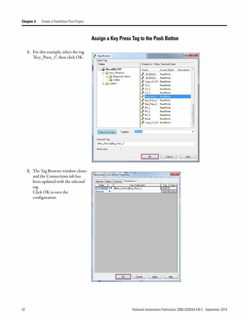
Assign a Key Press Tag to the Push Button
1. For this example, select the tag "Key_Press_1", then click OK.
2. The Tag Browser window closes and the Connections tab has been updated with the selected tag.Click OK to save the configuration.
32 Rockwell Automation Publication 2080-QS003A-EN-E - September 2014

Create a PanelView Plus Project Chapter 2
3. Repeat the instructions from step 1 to create momentary push button objects and assign global variable tags "Key_Press_2" and "Key_Press_3" to them.
Assign a Reset Tag to the Push Button
1. For this example, select the tag "Reset", then click OK.
Rockwell Automation Publication 2080-QS003A-EN-E - September 2014 33

Chapter 2 Create a PanelView Plus Project
2. The Tag Browser window closes and the Connections tab has been updated with the selected tag.Click OK to save the configuration.
34 Rockwell Automation Publication 2080-QS003A-EN-E - September 2014

Create a PanelView Plus Project Chapter 2
Assign a Copy CV_PV Tag to the Push Button
3. For this example, select the tag "Copy_CV_PV", then click OK.
4. The Tag Browser window closes and the Connections tab has been updated with the selected tag.Click OK to save the configuration.
You have finished creating the momentary push button objects and assigned the Key Press, Reset, and copy CV to PV tags to each object. In the next chapter, you will learn about the Micro800 controller global variables and how to use them.
Rockwell Automation Publication 2080-QS003A-EN-E - September 2014 35
Chapter 2 Create a PanelView Plus Project
Notes:
36 Rockwell Automation Publication 2080-QS003A-EN-E - September 2014

Chapter 3
Data Values Upload/Download
Introduction
In this chapter you will learn to use the PanelView Plus application that you created in the previous chapter to interact with the Micro800 controller global variables in Connected Components Workbench software.
Using Data Values Upload/Download
The Data Values Upload/Download feature allows you upload live logical values of variables that may have been changed by the operator in PanelView Plus (or program logic) and save them in your project as project values. Then optionally at download, the project values can be re-downloaded. The Data Values Upload/Download feature applies to both local and global variables, including instances of function blocks.
In Connected Components Workbench, when not monitoring the live logical values of variables, Connected Components Workbench will display a column named Project Values. Project Values are logical values which are saved in the project.
ATTENTION: If power is lost during the upload or download process, all user data will be lost.
Rockwell Automation Publication 2080-QS003A-EN-E - September 2014 37

Chapter 3 Data Values Upload/Download
In Connected Components Workbench, when in Debug mode and monitoring the live values of variables, Connected Components Workbench will display a column named Logical Values.
Note that the Initial Value column is shown in both non-debug mode and in debug mode. When a project is downloaded and both the Initial Value and Project Value are configured, then Initial Value has precedence and will be downloaded in to the live Logical Value.
Priority of Logical Values When Downloading
Project Value Initial Value Logical Value after Download
Exists Blank Project Value
Blank Exists Initial Value
Exists Exists Initial Value
38 Rockwell Automation Publication 2080-QS003A-EN-E - September 2014

Data Values Upload/Download Chapter 3
To begin, open the sample Micro820 controller project in Connected Components Workbench.
In this chapter you will learn how to do the following:
1. Download the Project on page 402. Change CV values and Upload the Project on page 433. Download the Project With Project Values on page 46
Rockwell Automation Publication 2080-QS003A-EN-E - September 2014 39

Chapter 3 Data Values Upload/Download
Download the Project
In this section, you will learn how to download the project to the Micro800 controller.
1. Click the M820-VAR tab to view the initial values assigned to the variables under the global variables tab.
2. Right-click on the controller project and select Download.
3. If your controller is in Remote Run mode, a dialog box appears to ask if you want to change to Remote Program mode. Click Yes to continue.
40 Rockwell Automation Publication 2080-QS003A-EN-E - September 2014

Data Values Upload/Download Chapter 3
4. A Download Confirmation dialog box appears. For this example, select Download.
When the Download option is selected, Connected Components Workbench software downloads the project to the controller. If any initial values have been assigned to either local or global variables, they will also be downloaded.
5. A download progress icon appears.
6. When the download is complete, the output window is updated.
7. A dialog box appears to ask if you want to change the controller to Remote Run mode. Click Yes to continue.
8. Click on the Debug icon to enter Debug mode.
Rockwell Automation Publication 2080-QS003A-EN-E - September 2014 41

Chapter 3 Data Values Upload/Download
9. Click the Micro820-VAR tab.In Debug mode, the controller has updated the values of the global variables from the project you just downloaded.
Note that the Initial Value has precedence over Project Value when downloading.
See Priority of Logical Values When Downloading on page 38 for more information.
10. The values of the global variables are also updated on the PanelView Plus application.
You have finished downloading the project to the controller. In the next section, you will learn how to change the values of the counter variables (CV) and upload the changes to the controller.
Values have been updated
42 Rockwell Automation Publication 2080-QS003A-EN-E - September 2014

Data Values Upload/Download Chapter 3
Change CV values and Upload the Project
In this section, you will change the value of the counter variables (CV), copy the values to the project variables (PV), and upload the changes to the controller.
1. Use the Key Press push button to increment the values of the counter variables (CV).
2. Observe the new values of the counter variables (CV) in the controller.
Values have been incremented
Rockwell Automation Publication 2080-QS003A-EN-E - September 2014 43

Chapter 3 Data Values Upload/Download
3. Click the Copy CV to PV push button to copy the values from the counter variables (CV) to the project variables (PV).
4. While connected to the controller but not in Debug mode, right-click on the controller project and select Upload.
5. A dialog box appears to ask if you want to replace the current project’s contents. Click Yes to continue.
Values have been copied from CV
44 Rockwell Automation Publication 2080-QS003A-EN-E - September 2014

Data Values Upload/Download Chapter 3
6. An Upload progress icon appears.
7. When the upload is complete, the output window is updated.
8. Click the Micro820-VAR tab.Since Connected Components Workbench is not in Debug mode, Connected Components Workbench will show the Project Value column which contains the recently uploaded logical values.
You must click Save if you want to permanently save the values in the project.
You have finished changing the values of the counter variables (CV) and uploaded the changes to the controller. In the next section you will learn how to download the project with project values.
Rockwell Automation Publication 2080-QS003A-EN-E - September 2014 45

Chapter 3 Data Values Upload/Download
Download the Project With Project Values
In this section, you will learn how to download the project with the project values to the Micro800 controller.
1. Right-click the controller project and select Download.
2. If your controller is in Remote Run mode, a dialog box appears to ask if you want to change to Remote Program mode. Click Yes to continue.
3. A Download Confirmation dialog box appears. For this example, select Download with Project Values.
The Project Values will be downloaded, but if the variable also has an Initial Value, it will take precedence over the Project Value.
4. A download progress icon appears.
46 Rockwell Automation Publication 2080-QS003A-EN-E - September 2014

Data Values Upload/Download Chapter 3
5. When the download is complete, the output window is updated.
6. A dialog appears to ask if you want to change the controller to Remote Run mode. Click Yes to continue.
7. Click on the Debug icon to enter Debug mode.
8. Click the Micro820-VAR tab.The controller has updated the values of the global variables from the project you just downloaded.
Note that Project Values for local variables are also downloaded but not shown here.
See Priority of Logical Values When Downloading on page 38 for more information.
Rockwell Automation Publication 2080-QS003A-EN-E - September 2014 47

Chapter 3 Data Values Upload/Download
9. The values of the global variables are also updated on the PanelView application.
10. Use the Key Press push button to increment the values of the counter variables (CV).
Values have been copied from CV
Values have been incremented
48 Rockwell Automation Publication 2080-QS003A-EN-E - September 2014

Data Values Upload/Download Chapter 3
11. Observe the new values of the counter variables (CV) in the controller.
You have finished downloading the project with project values. In the next chapter, you will learn how to Export and Import the global variables.
Using Backup and Restore
The Backup and Restore function works the same way as Data Value Upload and Download.
Rockwell Automation Publication 2080-QS003A-EN-E - September 2014 49

Chapter 3 Data Values Upload/Download
Notes:
50 Rockwell Automation Publication 2080-QS003A-EN-E - September 2014

Chapter 4
Variable Export/Import
Introduction
In this chapter, you will learn how to export the Micro800 controller global variables from a Connected Components Workbench project to your PC, edit the variables, and import the global and local variables into your project. This can be useful for editing and managing your global and local variables among multiple projects and with FactoryTalk View Studio.
Using Variable Export/Import
The Variable Export/Import feature allows you to export the Micro800 controller’s variables to a PC, edit the values of the variables, and import the variables back to the Micro800 controller.
Rockwell Automation Publication 2080-QS003A-EN-E - September 2014 51

Chapter 4 Variable Export/Import
To begin, open the sample Micro820 controller project in Connected Components Workbench.
In this chapter you will learn how to do the following:
1. Export Global Variables on page 532. Edit Global Variables on page 553. Import Global Variables on page 56
For this example, only the steps to export/import global variables are shown. You can also use the following steps to export/import local variables by right-clicking on the POU/Program instead of the controller.
52 Rockwell Automation Publication 2080-QS003A-EN-E - September 2014

Variable Export/Import Chapter 4
Export Global Variables
In this section you will learn how to export the global variables of your Micro800 controller project to an editable file.
1. Right-click the controller project and select Variable Export/Import.
2. In the Variable Export/Import dialog box, click the Export Variables tab, then click on Browse.
Rockwell Automation Publication 2080-QS003A-EN-E - September 2014 53
Chapter 4 Variable Export/Import
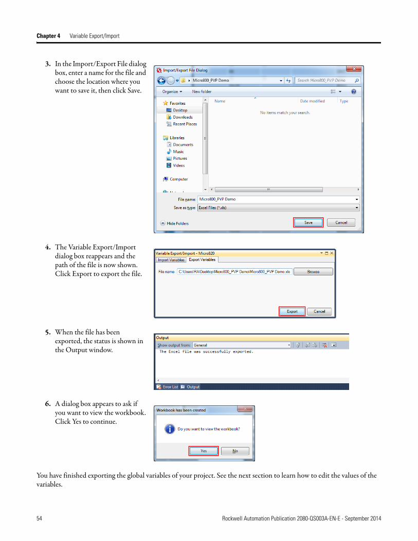
3. In the Import/Export File dialog box, enter a name for the file and choose the location where you want to save it, then click Save.
4. The Variable Export/Import dialog box reappears and the path of the file is now shown. Click Export to export the file.
5. When the file has been exported, the status is shown in the Output window.
6. A dialog box appears to ask if you want to view the workbook. Click Yes to continue.
You have finished exporting the global variables of your project. See the next section to learn how to edit the values of the variables.
54 Rockwell Automation Publication 2080-QS003A-EN-E - September 2014

Variable Export/Import Chapter 4
Edit Global Variables
In this section, you will learn how to edit the values of the Micro800 controller global variables that you have exported in the previous section. The global variable file is saved in the (.xls) format and can be opened using the Microsoft Excel program.
1. Open the global variable file in Microsoft Excel to view the values of each variable.
2. To change the values of the variables, just enter the new value into the appropriate cell.For this example, change the value of "PV_1" to 95 and "PV_3" to 80.
3. Click the Save icon or press Ctrl+S to save the file.
You have finished editing the values of the global variables. See the next section to learn how to import the file into your project.
Rockwell Automation Publication 2080-QS003A-EN-E - September 2014 55

Chapter 4 Variable Export/Import
Import Global Variables
In this section you will learn how to import the global variable file that you have edited in the previous section into your project.
1. Right-click the controller project and select Variable Export/Import.
2. In the Variable Export/Import dialog box, click the Import Variables tab, then click on Browse.
56 Rockwell Automation Publication 2080-QS003A-EN-E - September 2014
Variable Export/Import Chapter 4
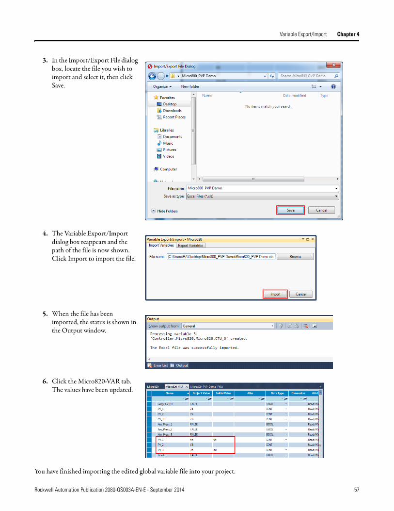
3. In the Import/Export File dialog box, locate the file you wish to import and select it, then click Save.
4. The Variable Export/Import dialog box reappears and the path of the file is now shown. Click Import to import the file.
5. When the file has been imported, the status is shown in the Output window.
6. Click the Micro820-VAR tab. The values have been updated.
You have finished importing the edited global variable file into your project.
Rockwell Automation Publication 2080-QS003A-EN-E - September 2014 57

Chapter 4 Variable Export/Import
Editing Array Data Types
If your global variables contain array data types, the way it is displayed in Connected Components Workbench and Microsoft Excel is different. See the examples below.
Array Data Type in Connected Components Workbench
Array Data Type in Microsoft Excel
Note how the Initial Value of the array indexes are displayed in the two examples shown above. If multiple indexes have the same Initial Value, they are grouped together in the format "x(y)" where "x" is the number of indexes and "y" is the Initial Value.
58 Rockwell Automation Publication 2080-QS003A-EN-E - September 2014

Appendix A
Data Types
Supported Data Types The following data types are supported.
When you see the controller variables in PanelView Plus, it will be shown as described in the table below.
Structured data types are NOT supported.
When Using Array Variables
A variable can be created as an array of data types and up to three dimensions are supported. The following rules must be observed when using an array of data types.
1. An array cannot be a Boolean data type.
2. An array cannot be an Array data type.
Data Type Hex Value Dec Value Description
BOOL 0xC1 193 Logical Boolean with values TRUE(1) and FALSE(0)
SINT 0xC2 194 Signed 8-bit integer value.
INT 0xC3 195 Signed 16-bit integer value.
DINT 0xC4 196 Signed 32-bit integer value.
LINT(1)
(1) LINT data types are not fully supported in PanelView Plus. When using LINT tags, values that are less than 53 bits are not displayed correctly or may appear wireframed on the display client.
0xC5 197 Signed 64-bit integer value.
USINT 0xC6 198 Unsigned 8-bit integer value.
UINT 0xC7 199 Unsigned 16-bit integer value.
UDINT 0xC8 200 Unsigned 32-bit integer value.
ULINT 0xC9 201 Unsigned 64-bit integer value.
REAL 0xCA 202 32-bit floating point value.
LREAL 0xCB 203 64-bit floating point value.
STRING(2)
(2) The STRING data type does not support Unicode.
0xDA 218 Character string.
Data Type (Micro800) Appears as Data Type (PanelView Plus)
BYTE USINT
WORD UINT
DWORD UDINT
LWORD ULINT
Rockwell Automation Publication 2080-QS003A-EN-E - September 2014 59

Appendix A Data Types
3. The starting index of the array must be zero.
An example of an array variable in Connected Components Workbench is shown below. The index of the array is shown in square brackets.
When assigning a tag to an object in your PanelView Plus application, you can assign a specific index of an array by doing the following:
1. In the Tag Browser window, select the Online -> Array_Data_Type folder.A list of tags of the array and each of its index is displayed.
2. Select the tag of the array with the desired index, then click OK.
60 Rockwell Automation Publication 2080-QS003A-EN-E - September 2014

Rockwell Automation Publication 2080-QS003A-EN-E - September 2014 61

Rockwell Otomasyon Ticaret A.Ş., Kar Plaza İş Merkezi E Blok Kat:6 34752 İçerenköy, İstanbul, Tel: +90 (216) 5698400
Rockwell Automation Publication 2080-QS003A-EN-E - September 2014 62Copyright © 2014 Rockwell Automation, Inc. All rights reserved.
Rockwell Automation Support
Rockwell Automation provides technical information on the Web to assist you in using its products. At http://www.rockwellautomation.com/support/, you can find technical manuals, a knowledge base of FAQs, technical and application notes, sample code and links to software service packs, and a MySupport feature that you can customize to make thebest use of these tools.
For an additional level of technical phone support for installation, configuration, and troubleshooting, we offer TechConnect support programs. For more information, contact your local distributor or Rockwell Automation representative, or visit http://www.rockwellautomation.com/support/.
Installation Assistance
If you experience a problem within the first 24 hours of installation, review the information that is contained in this manual.You can contact Customer Support for initial help in getting your product up and running.
New Product Satisfaction Return
Rockwell Automation tests all of its products to ensure that they are fully operational when shipped from the manufacturing facility. However, if your product is not functioning and needs to be returned, follow these procedures.
Documentation Feedback
Your comments will help us serve your documentation needs better. If you have any suggestions on how to improve this document, complete this form, publication RA-DU002, available at http://www.rockwellautomation.com/literature/.
United States or Canada 1.440.646.3434
Outside United States or Canada
Use the Worldwide Locator at http://www.rockwellautomation.com/support/americas/phone_en.html, or contact your local Rockwell Automation representative.
United States Contact your distributor. You must provide a Customer Support case number (call the phone number above to obtain one) to your distributor to complete the return process.
Outside United States Please contact your local Rockwell Automation representative for the return procedure.